Embed Size (px)
Citation preview

Design of a 1-D Sonic AnemometerMDR Presentation
Group Members: Vanessa Dubé , Michael Jao, Chethan Srinivasa, Robert Vice
Advisors: Professor Jackson (ECE Department), Professor Voss (Geoscience Department)

Background
• What is a Sonic Anemometer?– Device that measures windspeed
• What is unique about our anemometer?– Will measure small windspeeds– Will be utilized by the Geoscience Department
for weather research

Background (Cont’d)
• Anemometer uses transducers to send and receive acoustic signals through air
• Used two transmitters and two receivers
• Absolute time will vary with windspeed
• Sine wave sent from function generator to both transmitters
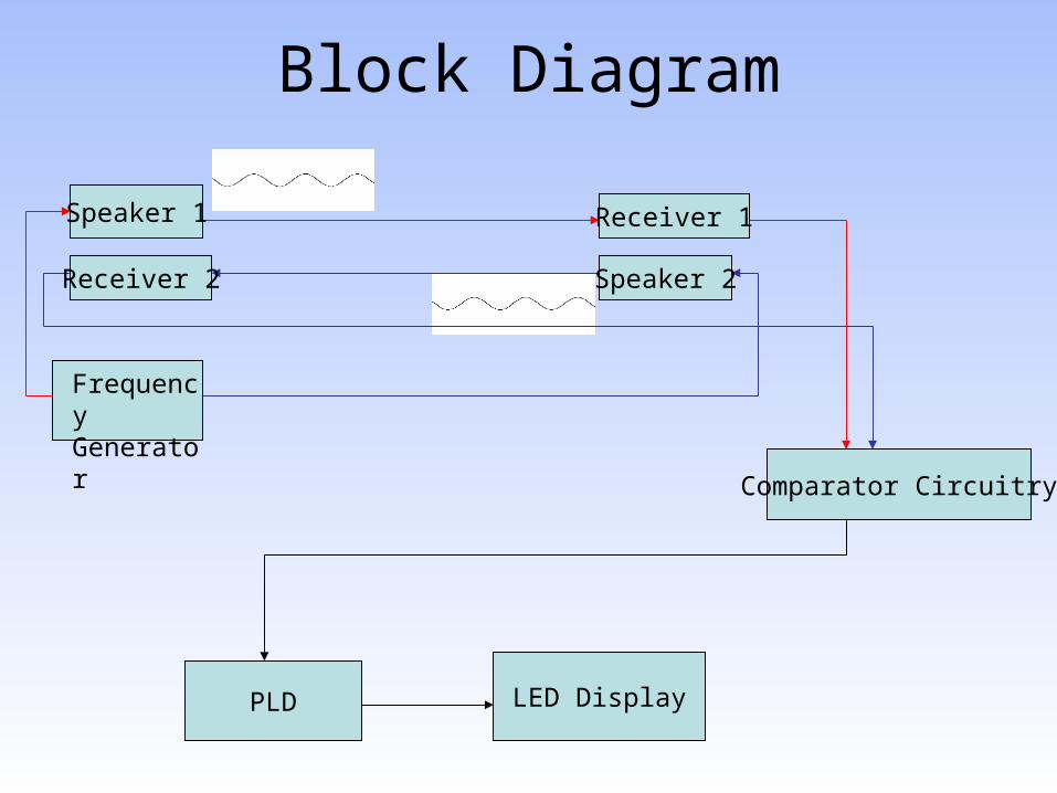
Block Diagram
FrequencyGenerator
Comparator Circuitry
LED DisplayPLD
Speaker 1
Receiver 2 Speaker 2
Receiver 1
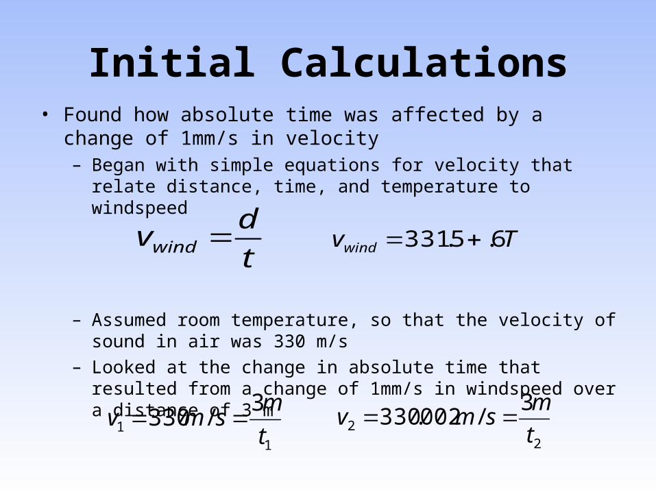
Initial Calculations• Found how absolute time was affected by a change of 1mm/s
in velocity– Began with simple equations for velocity that relate distance,
time, and temperature to windspeed
– Assumed room temperature, so that the velocity of sound in air was 330 m/s
– Looked at the change in absolute time that resulted from a change of 1mm/s in windspeed over a distance of 3 m
t
dvwind Tvwind 6.5.331
11
3/330
t
msmv
22
3/002.330
t
msmv
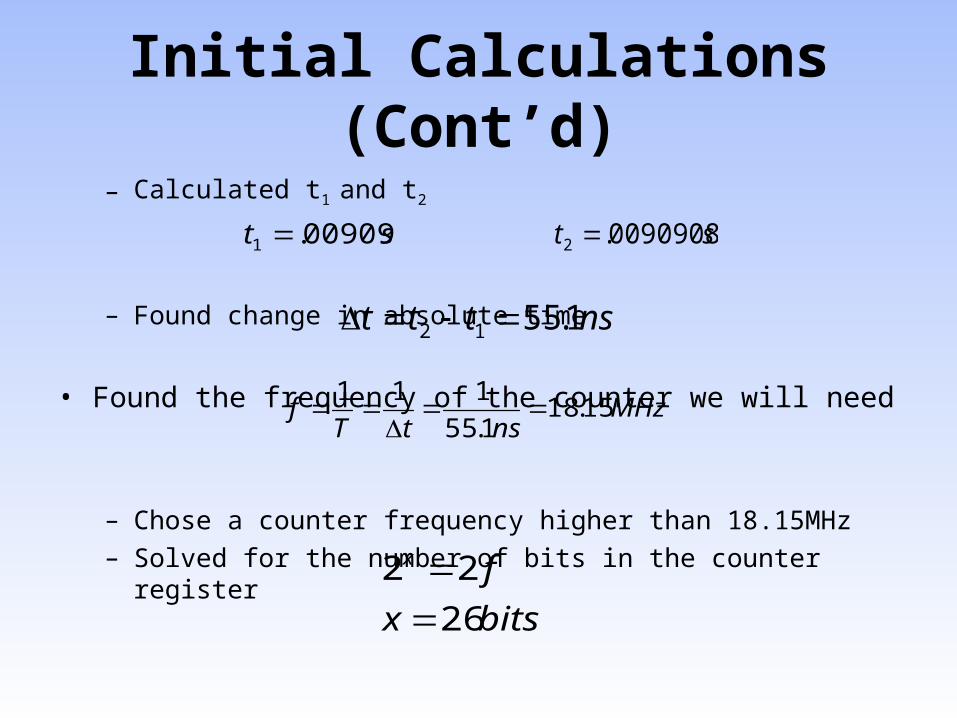
Initial Calculations (Cont’d)
– Calculated t1 and t2
– Found change in absolute time
• Found the frequency of the counter we will need
– Chose a counter frequency higher than 18.15MHz – Solved for the number of bits in the counter register
st 00909.1 st 0090908.2
nsttt 1.5512
MHznstT
f 15.181.55
111
bitsx
fx
26
22

Zero Crossing Detector
• Chose to convert sine waves to digital signals using LM339 Comparator
• Digital signal is high only when the amplitude of the sine wave is greater than zero
• Used digital signals to determine zero crossings of sine waves
• Phase difference of two received waves is the difference in zero crossing locations

Comparator
• Used LM339 because it operates at a higher frequencies and has less delay time
• Comparator circuitry:

Comparator (Cont’d)•Input and output waveforms of comparator circuitry
Comparator (Cont’d)
• Calculations go here

Transducers• Part numbers P9895-ND and P9894-ND• One for transmit and one for receive• Lowest frequency for cost effectiveness and familiarization• Nominal frequency 40.0 kHz• Temperature range -40-100°C
Sensitivity
is 0dB1V
Pa

• Optimal measured frequency of 40.2 kHz
• Continuous sine input for optimal received
signal
Transducers (Cont’d)

Test Setup
• DC fan• 4”x84” PVC drain pipe• Quick-cap (end cap)• 6’x2”x2” pine board with
5” slots• Wendy’s™ straws• CD case for mounts• Twisted pair insulated
wire

Wind Flow Testing
• Developed method to test windspeed generated by fan

Wind Flow Testing (Cont’d)
Measuring w ith Incense on small PVC
R2 = 0.9636y = 0.1052x - 0.1267
0
0.2
0.4
0.6
0.8
1
1.2
1.4
0 5 10 15
Voltage (V)
Win
dspe
ed o
f Fan
(m/s
) Windspeed vs. Voltage
Linear (Windspeed vs.Voltage)
Linear (Windspeed vs.Voltage)

Wind Flow Testing (Cont’d)
Windspeed vs. Voltage Measured w /Ultrasonic Anemometer (Linear section)
y = 0.0418x - 0.0271R2 = 0.9867
0
0.05
0.1
0.15
0.2
0.25
0.3
0.35
0 2 4 6 8
Voltage (V)
Win
dsp
eed
(m
/s)
Windspeed vs. Voltage
Linear (Windspeed vs.Voltage)

Wind Flow Testing (Cont’d)
• Read phase difference from oscilloscope
• Compared generated windspeed to windspeed ovserved by system
• Found the observed windspeed to be relatively close to the actual windspeed
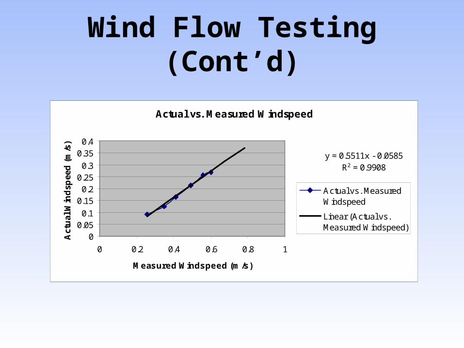
Wind Flow Testing (Cont’d)
Actual vs. Measured Windspeed
y = 0.5511x - 0.0585R2 = 0.9908
00.050.1
0.150.2
0.250.3
0.350.4
0 0.2 0.4 0.6 0.8 1
Measured Windspeed (m/s)
Act
ual
Win
dsp
eed
(m
/s)
Actual vs. MeasuredWindspeed
Linear (Actual vs.Measured Windspeed)

PLD/Counter
• PLD Controller (Left)
- For direction and clock signal
•PLD Counter (Right)
- Temporary until counter is received
• 4 MHz clock (will use 125MHz )

Complications
• Comparator Offset
• High freq wave
• Noise in System
• Amplification
• Etc

Expenses
Balance -500.00 Prof Voss Account Remaining -476.35 VossBalance -500.00 SDP Account Remaining -523.65 SDP
Total Spent $23.65Total Remain -976.35
Item Type Description Stock No. Catalog Price Quantity Price PriceTransducer Reciever, 40kHz, -40ºC to 100ºC, 4kHz bandwidth P9894-ND DigiKey $9.20 2 $18.40 $0.00Transducer Transmitter,40kHz, -40ºC to 100ºC, 4kHz bandwidth P9895-ND DigiKey $9.20 2 $18.40 $0.00OP-AMP IC HS CMOS Dual OP AMP 8 Dip OP2350PA-ND DigiKey $4.34 4 $0.00 $17.36Pipe 4" x 10' PVC Drain Pipe - Solid 4"x10' White Cowls $6.29 1 $0.00 $6.29
Samples (used in design)Prof. Ciesielski Altera Max7000 7032-12 PLD's and Mount 3

Conclusions
• Met Specs!