Embed Size (px)
Citation preview

“Design of 400/220kV Sub-station”
S.M. MUJUMDARGeneral Manager
(sub-station Engineering)
27th April 2005 Jyoti Structures Ltd., Mumbai
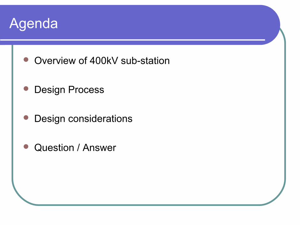
Agenda
Overview of 400kV sub-station
Design Process
Design considerations
Question / Answer

Imp. considerations in substation design
Safety of personnel and equipment Reliability and Security Adherence to
Statutory obligations
– I.E. rules, Environmental aspects Electrical design considerations Structural design considerations
Ease of maintenance Possibility to Expand

System parameters
1000 mV
(156kV)
1000 mV
(320kV)
Radio interference voltage at 1MHZ (for phase to earth voltage)
10.
40kA40kARated short ckt. Current for 1 sec.8.
25mm/kV25mm/kVMin. creepage distance7.
156kV320kVCorona Extinction voltage 6.
Effectively earthedSystem neutral earthing5.
33Number of phases4.
50Hz50HzRated frequency3.
245kV420kVMax. operating voltage2.
220kV400kVNominal system voltage1.
220kV400kVDescriptionSr.

System parameters Contd..
Remarks220kV400kVDescriptionSr.
(Line-ground)
(open terminals)
460kV
460kV
530kV
460kV
680kV
520kV
610kV
630kV
iii) One min. power freq.
withstand voltage (dry/wet)
-- for lines
-- for CB / Isolator
-- for other equipments
1050kVpii) Switching impulse
withstand voltage (dry/wet)
1050kVp
950kVp
1050kVp
1550kVp
1300kVp
1425kVp
Rated insulation levels
i) Full wave impulse
withstand voltage
-- for lines
-- for reactor/ X’mer
-- for other equipments
11.

Substation Bird’s view

400kV Circuit Breaker
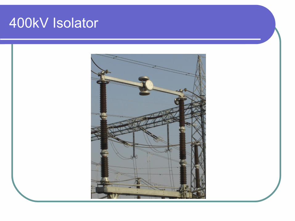
400kV Isolator
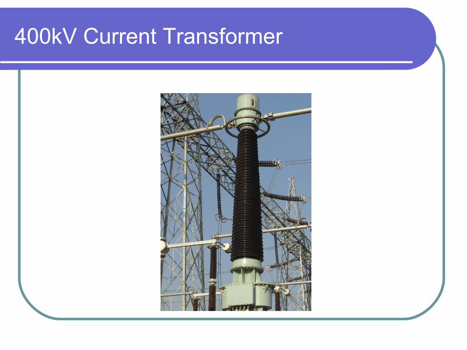
400kV Current Transformer

400kV CVT

400kV Surge Arrester

Shunt Reactor & NGR

400/220 kV Auto Transformer

400kV Bus Post Insulator

Wave Trap


Functions of substation equipments
To discharge lightning over voltages and switching over voltages to earth
7. Lightning Arrester
To step-down voltages for measurement, control & protection
6. Voltage Transformer
To step-down currents for measurement, control & protection
5. Current Transformer
To discharge the voltage on dead lines to earth4. Earthing switch
Disconnection under no-load condition for safety, isolation and maintenance.
3. Isolators
Automatic switching during normal or abnormal conditions
2. Circuit Breaker
Incoming & outgoing ckts. Connected to bus-bar1. Bus-Bar
FunctionEquipment

Functions of substation equipments Contd…
Compensation of long lines.14. Series Capacitor
To step-up or step-down the voltage and transfer power from one a.c. voltage another a.c. voltage at the same frequency.
13. Power Transformer
To provide compensations to reactive loads of lagging power factors
12. Shunt capacitors
To prevent high frequency signals from entering other zones.
11. Line –Trap
To provide connection between high voltage line & PLCC equipment
10. Coupling capacitor
To limit earth fault current9. Neutral-Grounding resistor
To control over voltages by providing reactive power compensation
8. Shunt reactor
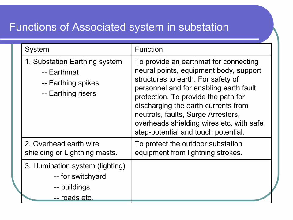
Functions of Associated system in substation
3. Illumination system (lighting)
-- for switchyard
-- buildings
-- roads etc.
To protect the outdoor substation equipment from lightning strokes.
2. Overhead earth wire shielding or Lightning masts.
To provide an earthmat for connecting neural points, equipment body, support structures to earth. For safety of personnel and for enabling earth fault protection. To provide the path for discharging the earth currents from neutrals, faults, Surge Arresters, overheads shielding wires etc. with safe step-potential and touch potential.
1. Substation Earthing system
-- Earthmat
-- Earthing spikes
-- Earthing risers
FunctionSystem

Contd..
To provide alarm or automatic tripping of faulty part from healthy part and also to minimize damage to faulty equipment and associated system.
4. Protection system
-- protection relay panels
-- control cables
-- circuit breakers
-- CTs, VTs etc.
For Protective circuits, control circuits, metering circuits, communication circuits
5. Control cable
For communication, telemetry, tele-control, power line carrier protection etc.
7. PLCC system power line carries communication system
-- line trap
-- coupling capacitor
-- PLCC panels
To provide supply path to various auxiliary equipment and machines.
6. Power cable
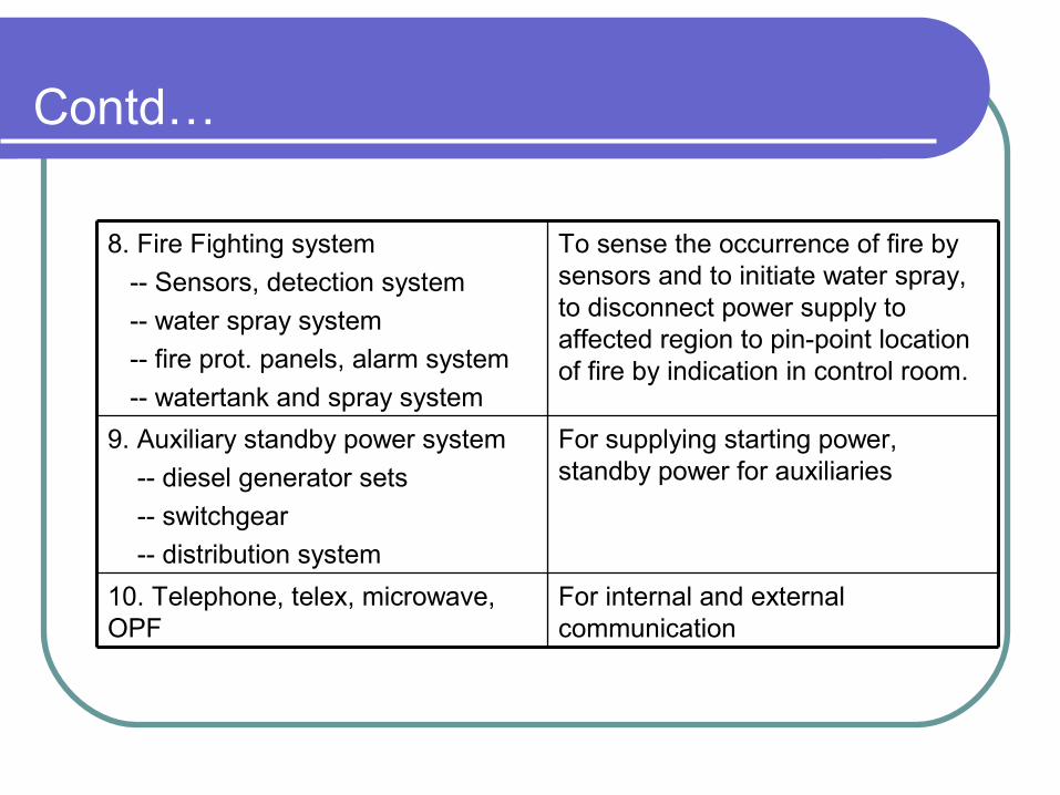
Contd…
To sense the occurrence of fire by sensors and to initiate water spray, to disconnect power supply to affected region to pin-point location of fire by indication in control room.
8. Fire Fighting system
-- Sensors, detection system
-- water spray system
-- fire prot. panels, alarm system
-- watertank and spray system
For internal and external communication
10. Telephone, telex, microwave, OPF
For supplying starting power, standby power for auxiliaries
9. Auxiliary standby power system
-- diesel generator sets
-- switchgear
-- distribution system
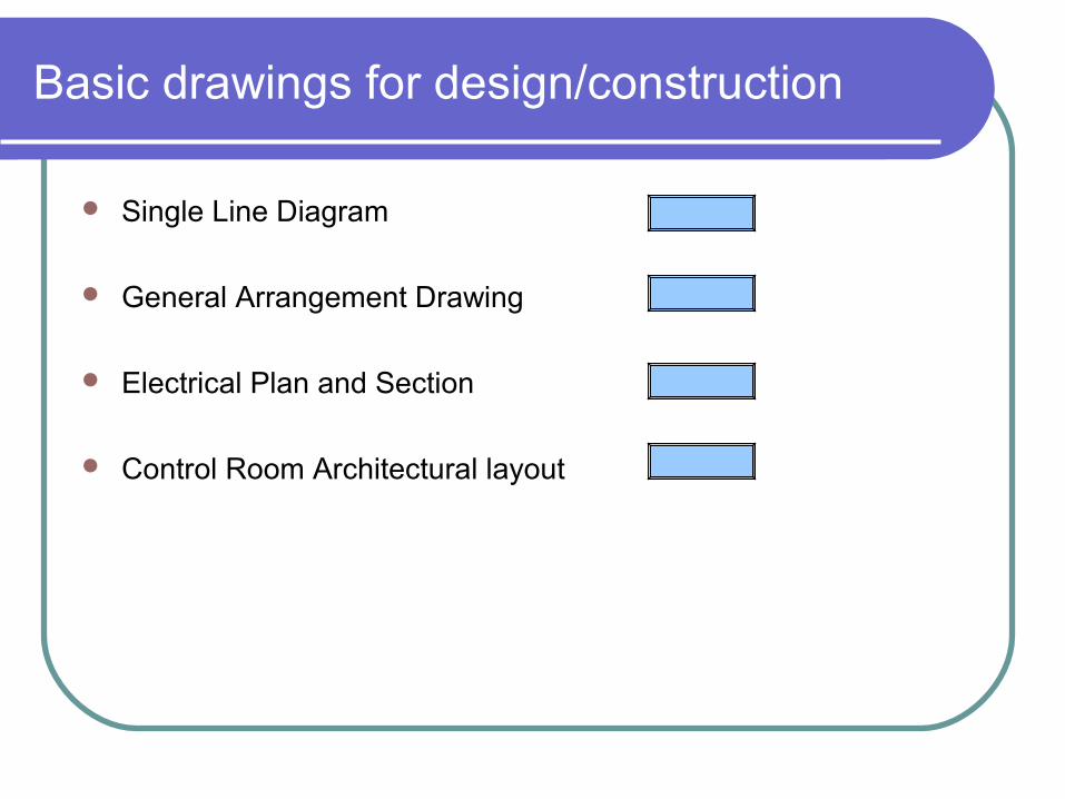
Basic drawings for design/construction
Single Line Diagram
General Arrangement Drawing
Electrical Plan and Section
Control Room Architectural layout
Supporting drawings
Structural layout
Earthmat layout
Civil layout
Erection Key Diagram
Lighting Layout
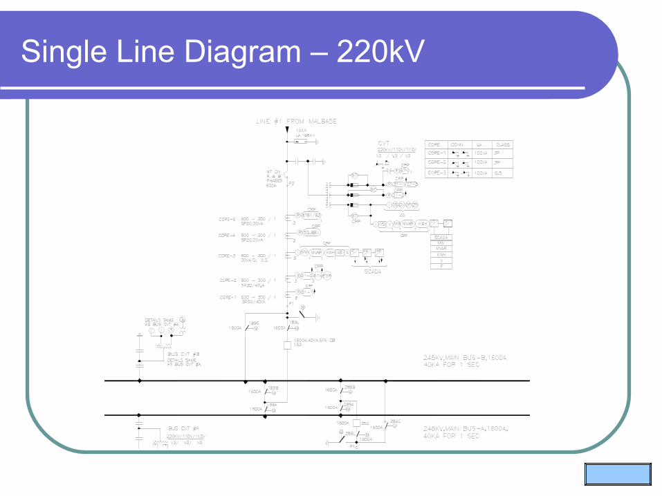
Single Line Diagram – 220kV

General arrangement layout

Electrical layout

Electrical Section

Control room layout

Control room layout
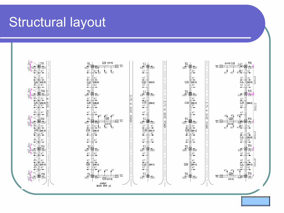
Structural layout
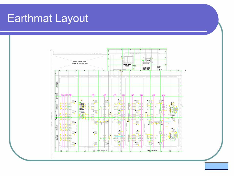
Earthmat Layout
@
@
@
@
@
@
@
@
@

Civil layout

Erection Key Diagram
EW2EW2
4S1
4S1
4DTTM-2
EW1
4I
4S1
4LA 4P 4V4S1 4W4W
4S14S1
4I
4S1
4LA4S1
R1
4SSTM-D
4T14T14T1
4S1 4S14S1
EW2EW2
4S1
4S1
4S1
4DTTM-1 4S24S2 4S2
EW1
4SSTM-D
4TBSM4TBSM 4TBSM
4P14I4P34S1 4S1
4P14I4IC1
4S1 4S14S1
4B4I2 4I14I4IC2
4S1
4C24C1 4I14B
EW2EW2
4SSTM-T
4S2 4S24TM
4S1 4S14S1
4DTTM-14DTTM-2
EW1
4S24S2 4S2
4I2
4S1
4IC2
4DTTM-1
4DTTM-1
4DTTM-1
4DTTM-1
4DTTM-1
4DTTM-1
4SSTM-D
4LA
4P
4P
4P
4LA
4LA
4W
4V
4V
4V
4W
4SSTM-D
4DTTM-1
4DTTM-1
4DTTM-1
4SSTM-D
4I
4I
4I
4I
4I
4I
4W
4P
4V
4LA
4P
4LA
4V
4P
4LA
4V
4W
4SSTM-D
4DTTM-1
4DTTM-1
4SSTM-D
4I
4I
4I
4I
4DTTM-1
4I
4SSTM-D
4I
4P3
R1
R1R1
4LA
4LA
4LA
4DTTM-2
4P3
4P3
4I
4I
4I
4DTTM-2
4I
4I
4DTTM-2
4I
R1
R1
R1
4LA
4LA
4LA
4P3
4P3
4I
4I
4DTTM-2
4DTTM-2
4I
4I
4P3
4I
4DTTM-2
4I
4B
4B
4B
4DTQB-24DTQB-2 4DTQB-2
4I2
4I1
4I
4P1
4IC2
4P1
4IC1 4I2
4I1
4I1
4B
4B
4B
4C2
4C1
4I1
4I2
4C2
4C1
4I1
4I2
4C2
4C1
4I1
4I2
4B
4B
4B
4P1
4I2
4I14IC2
4P1
4IC1
4I2
4I1
4I
4DTQB-14DTQB-1 4DTQB-1
4I1
4C2
4C1
4I1
4B
4I2
4B
4C2
4C1
4I1
4I2
4B
4C1
4C2
4I1
4I2
4W1
4W1
4W1
4W1
4W1
4W1
4W1
4W1
4W1
4W1
N1
R2
R2
N1

Lighting Design
Adequate lighting is necessary for safety of working personnel and O&M activities
Recommended value of Illumination level Control & Relay panel area - 350 Lux (at floor level) Test laboratory - 300 Lux Battery room - 100 Lux Other indoor area - 150 Lux Switchyard - 50 Lux (main equipment)
- 20 Lux (balance Area / road @ ground level)
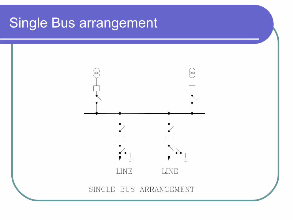
Single Bus arrangement
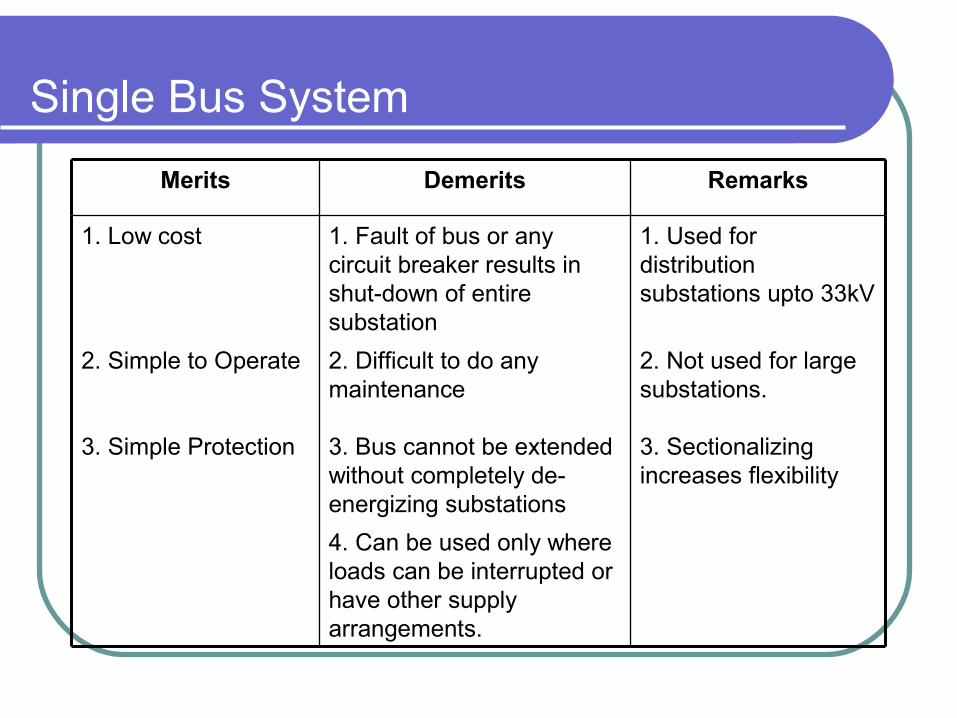
Single Bus System
4. Can be used only where loads can be interrupted or have other supply arrangements.
3. Sectionalizing increases flexibility
3. Bus cannot be extended without completely de-energizing substations
3. Simple Protection
2. Not used for large substations.
2. Difficult to do any maintenance
2. Simple to Operate
1. Used for distribution substations upto 33kV
1. Fault of bus or any circuit breaker results in shut-down of entire substation
1. Low cost
RemarksDemeritsMerits
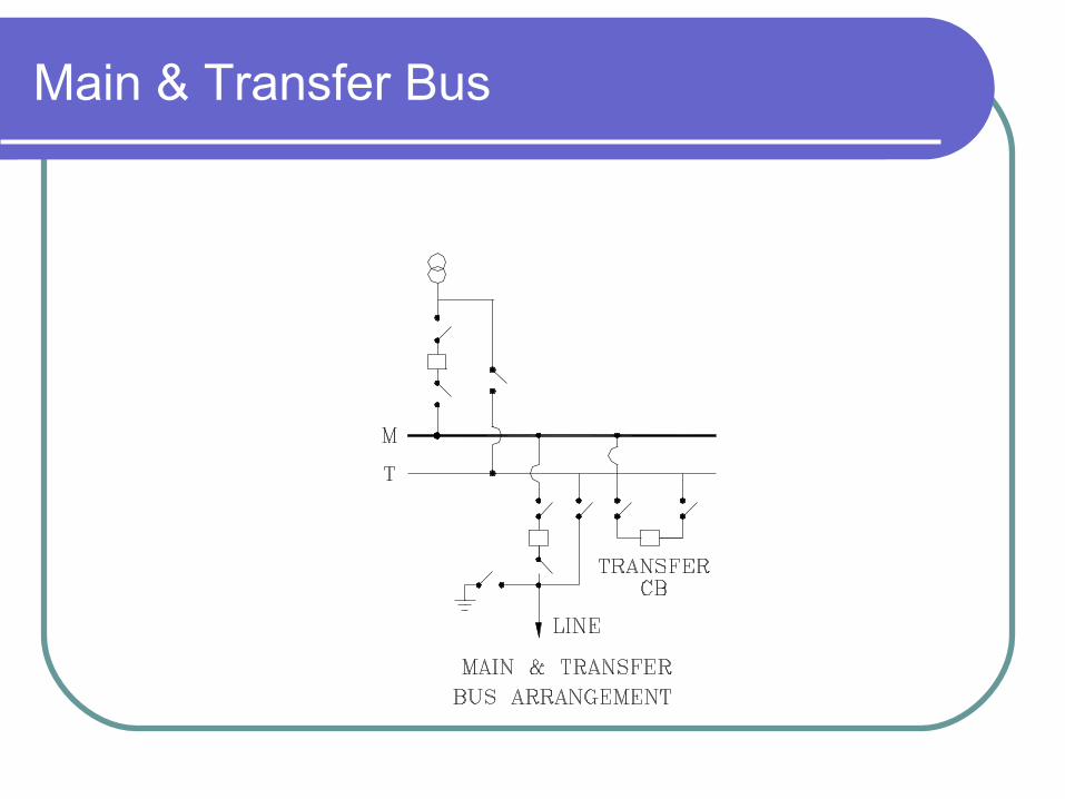
Main & Transfer Bus

Main & transfer busbar system
3. Fault of bus or any circuit breaker results in shutdown of entire substation.
3. Potential devices may be used on the main bus
. 2. Switching is somewhat complex when maintaining a breaker
2. Any breaker can be taken out of service for maintenance.
1. Used for 110kV substations where cost of duplicate bus bar system is not justified
1. Requires one extra breaker coupler
1. Low initial & ultimate cost
RemarksDemeritsMerits
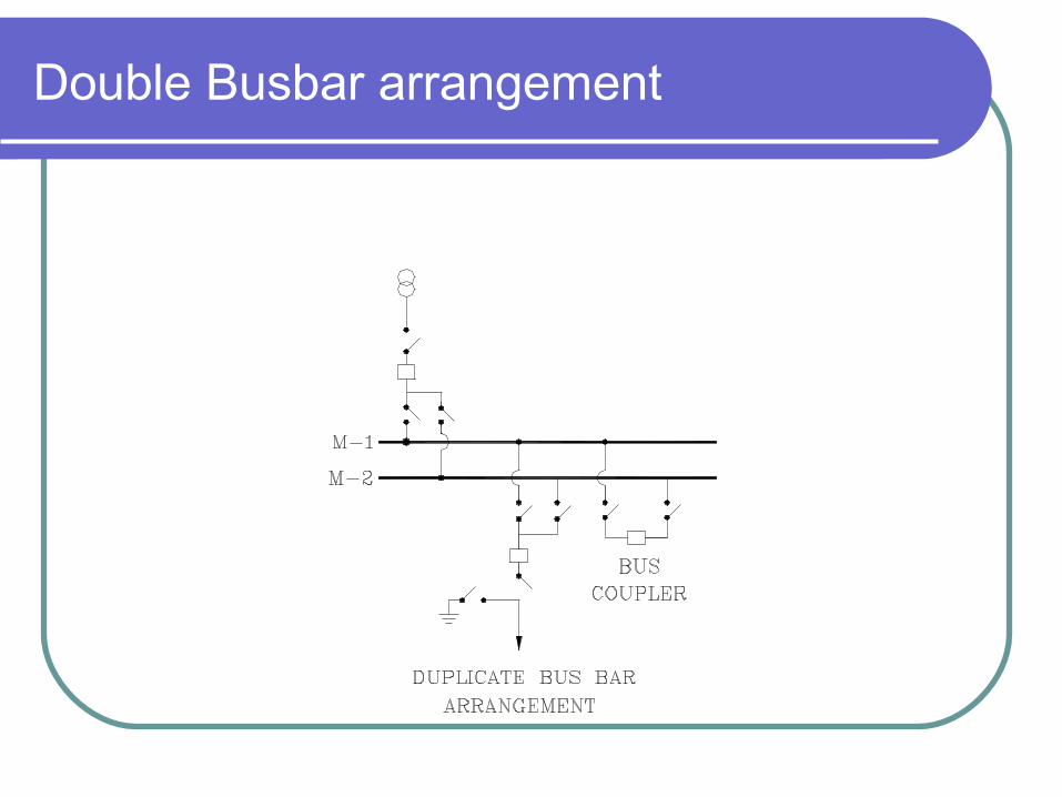
Double Busbar arrangement

Double Bus Bar Single Breaker system
5. Bus couplers failure takes entire substation out of service.
4. Line breaker failure takes all circuits connected to the bus out of service.
3. High exposure to bus fault.
2. Bus protection scheme may cause loss of substation when it operates.
2. Half of the feeders connected to each bus
1. Most widely used for 66kV, 132kv, 220kV and important 11kv, 6.6kV, 3.3kV substations.
1. Extra bus-coupler circuit breaker necessary.
1. High flexibility
RemarksDemeritsMerits
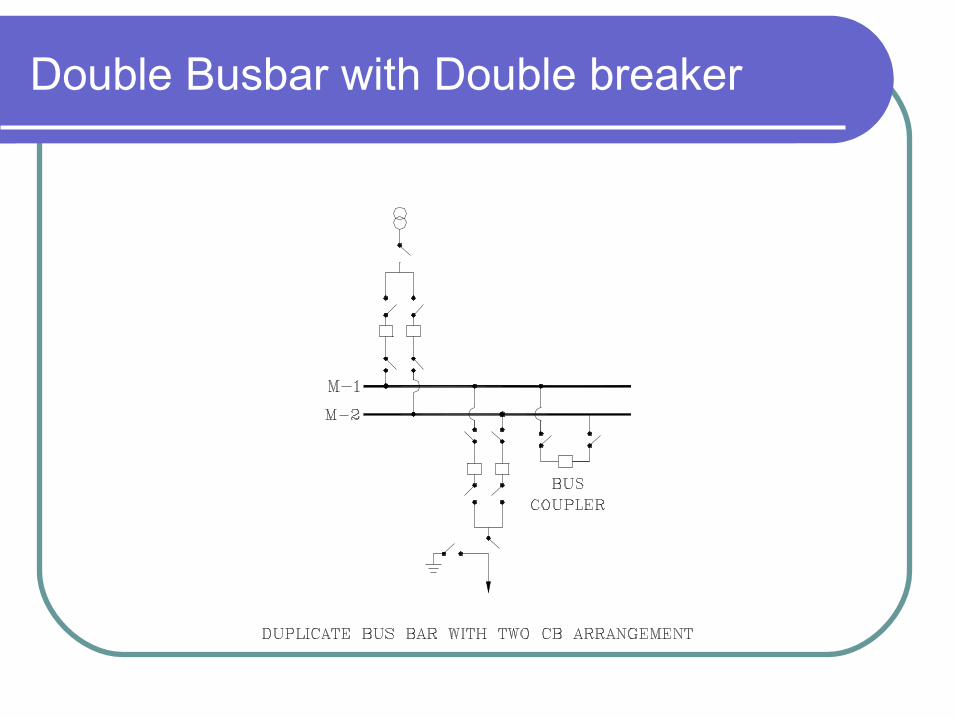
Double Busbar with Double breaker
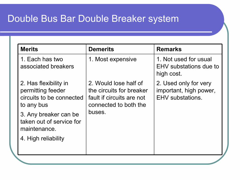
Double Bus Bar Double Breaker system
4. High reliability
3. Any breaker can be taken out of service for maintenance.
2. Used only for very important, high power, EHV substations.
2. Would lose half of the circuits for breaker fault if circuits are not connected to both the buses.
2. Has flexibility in permitting feeder circuits to be connected to any bus
1. Not used for usual EHV substations due to high cost.
1. Most expensive1. Each has two associated breakers
RemarksDemeritsMerits

Double main & transfer
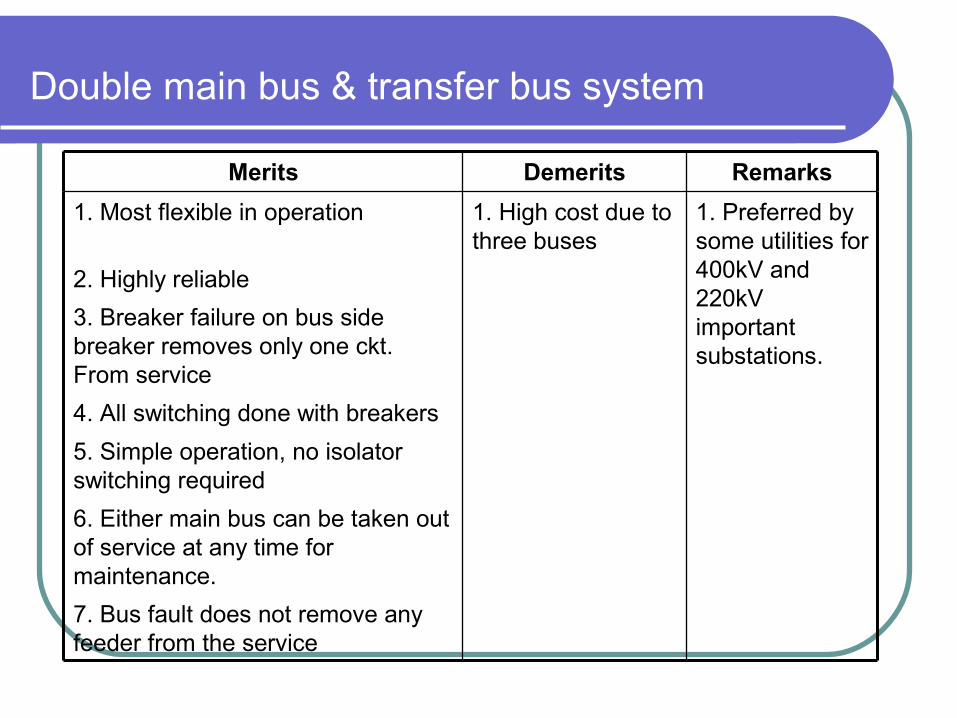
Double main bus & transfer bus system
7. Bus fault does not remove any feeder from the service
6. Either main bus can be taken out of service at any time for maintenance.
5. Simple operation, no isolator switching required
4. All switching done with breakers
3. Breaker failure on bus side breaker removes only one ckt. From service
2. Highly reliable
1. Preferred by some utilities for 400kV and 220kV important substations.
1. High cost due to three buses
1. Most flexible in operation
RemarksDemeritsMerits
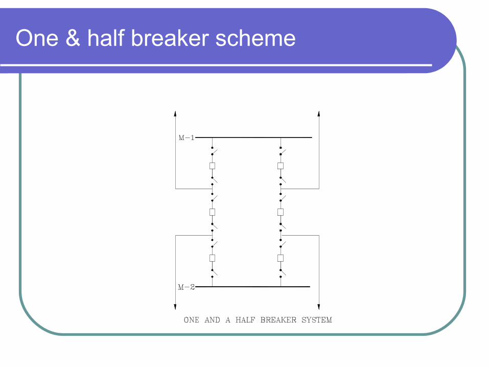
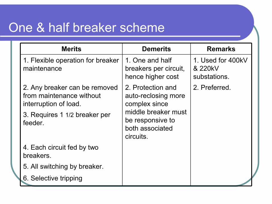
One & half breaker scheme
One & half breaker scheme
6. Selective tripping
5. All switching by breaker.
4. Each circuit fed by two breakers.
3. Requires 1 1/2 breaker per feeder.
2. Preferred.2. Protection and auto-reclosing more complex since middle breaker must be responsive to both associated circuits.
2. Any breaker can be removed from maintenance without interruption of load.
1. Used for 400kV & 220kV substations.
1. One and half breakers per circuit, hence higher cost
1. Flexible operation for breaker maintenance
RemarksDemeritsMerits

Ring Bus
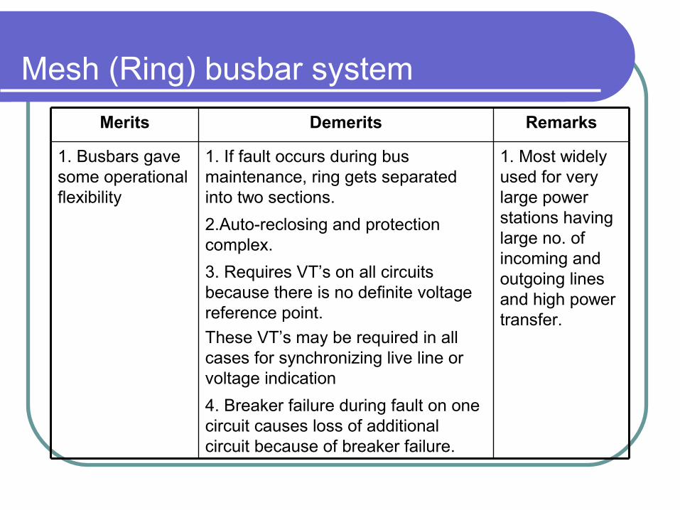
Mesh (Ring) busbar system
4. Breaker failure during fault on one circuit causes loss of additional circuit because of breaker failure.
3. Requires VT’s on all circuits because there is no definite voltage reference point.
These VT’s may be required in all cases for synchronizing live line or voltage indication
2.Auto-reclosing and protection complex.
1. Most widely used for very large power stations having large no. of incoming and outgoing lines and high power transfer.
1. If fault occurs during bus maintenance, ring gets separated into two sections.
1. Busbars gave some operational flexibility
RemarksDemeritsMerits
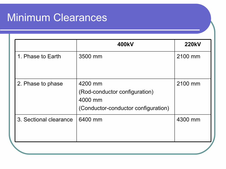
Minimum Clearances
4300 mm6400 mm3. Sectional clearance
2100 mm4200 mm
(Rod-conductor configuration)
4000 mm
(Conductor-conductor configuration)
2. Phase to phase
2100 mm3500 mm1. Phase to Earth
220kV400kV
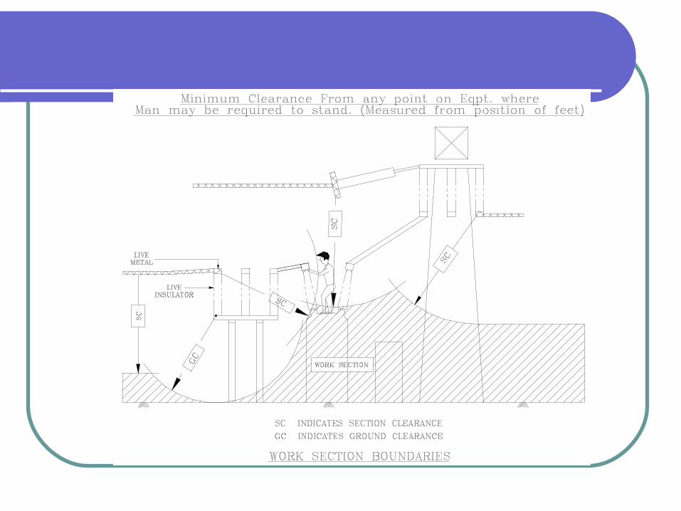


Clearance Diagram

Bus Bar Design
Continuous current rating. Ampacity caculation as per IEEE:738
Short time current rating (40kA for 1 Sec.) IEC-865
Stresses in Tubular Busbar
Natural frequency of Tubular Busbar
Deflection of Tube
Cantilever strength of Post Insulator
Aeolian Vibrations
Gantry Structure Design
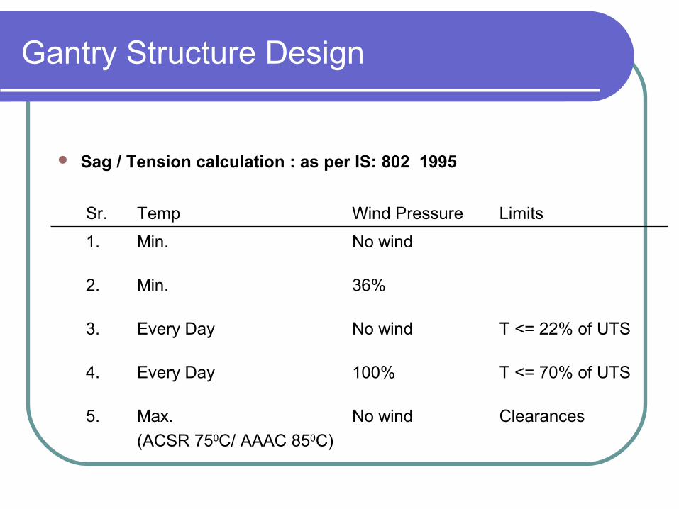
ClearancesNo windMax.
(ACSR 750C/ AAAC 850C)
5.
T <= 70% of UTS100%Every Day4.
T <= 22% of UTSNo windEvery Day3.
36%Min.2.
No windMin.1.
LimitsWind PressureTempSr.
Sag / Tension calculation : as per IS: 802 1995
Contd..
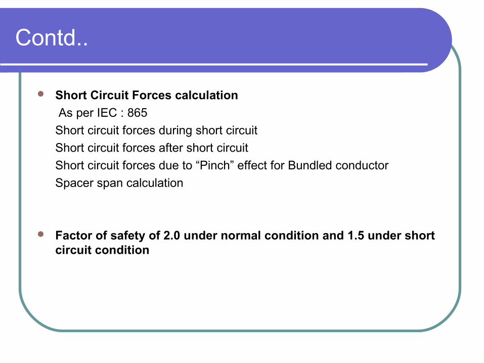
Short Circuit Forces calculation
As per IEC : 865
Short circuit forces during short circuit
Short circuit forces after short circuit
Short circuit forces due to “Pinch” effect for Bundled conductor
Spacer span calculation
Factor of safety of 2.0 under normal condition and 1.5 under short circuit condition
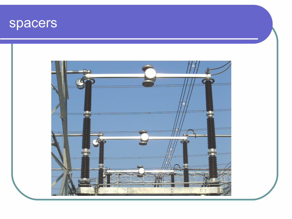
spacers
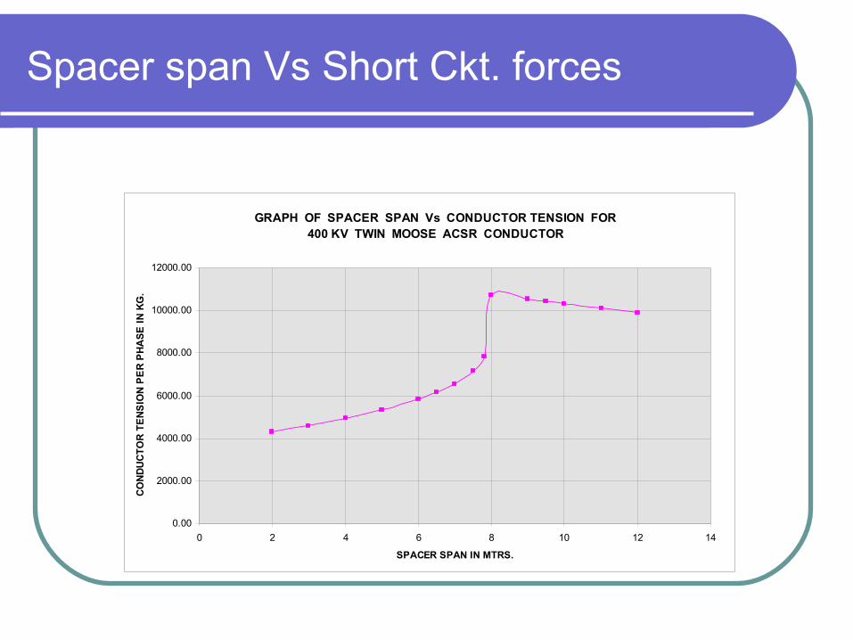
Spacer span Vs Short Ckt. forces
GRAPH OF SPACER SPAN Vs CONDUCTOR TENSION FOR 400 KV TWIN MOOSE ACSR CONDUCTOR
0.00
2000.00
4000.00
6000.00
8000.00
10000.00
12000.00
0 2 4 6 8 10 12 14
SPACER SPAN IN MTRS.
CO
ND
UC
TO
R T
EN
SIO
N P
ER
PH
AS
E I
N K
G.
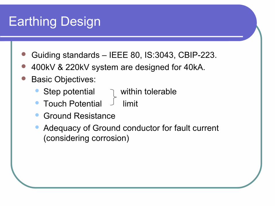
Earthing Design
Guiding standards – IEEE 80, IS:3043, CBIP-223. 400kV & 220kV system are designed for 40kA. Basic Objectives:
Step potential within tolerable Touch Potential limit Ground Resistance Adequacy of Ground conductor for fault current
(considering corrosion)

Touch and step potential

Lightning Protection – Ground Wire
FIG-4bFIG-4a

Lightning Protection – Lightning Mast