Embed Size (px)
Citation preview

Design No. G524
April 24, 2020
Restrained Assembly Ratings - 1, 1-1/2, and 2 Hr.
(See Items 2, 4A, 4D, 6, 6A, 6C, 7B, 10, 11, and 13)
Unrestrained Assembly Ratings — 1, 1-1/2, 2 and 3 Hr.
(See Items 2, 4A, 4D, 6, 6A, 6C, 6G, 6H, 7B, 10,11, and 13)
Unrestrained Beam Ratings — 1, 1-1/2, 2 and 3 Hr.
(See Items 2, 4A, 6A, 6C, 6G, 6H, 10 and 11)
This design was evaluated using a load design method other than the Limit States Design Method (e.g., Working Stress Design Method). For jurisdictions employing the Limit States
Design Method, such as Canada, a load restriction factor shall be used — See Guide BXUV or BXUV7
* Indicates such products shall bear the UL or cUL Certification Mark for jurisdictions
employing the UL or cUL Certification (such as Canada), respectively.


1. Beam — Min W6 x 9 for 1, 1-1/2 or 2 hr ratings, min W8x15 when used with Item 14 for 2 hr rating, and min W8 x
24 for 3 hr rating.
1A. Steel Girder — (Not Shown) — As an alternate to Item 1 for 1, 1-1/2, or 2 hr ratings:
Minimum girder depth - 10 in.
Minimum top chord size - 2-1/2 x 0.236 in. equal leg angle.
Minimum bottom chord size - 2 x 0.236 in. equal leg angle.
Minimum end diagonal size - 1-1/2 x 0.157 in. equal leg angle.
Minimum 1st interior diagonal size - 1-3/4 x 0.197 in. U-shape.
Minimum Remaining interior members - 1-3/8 x 0.118 in. U-shape.
1B. Channel Beam — As an alternate to Item 1 for 1, 1-1/2, or 2 hr ratings
Minimum depth - 4 in.
Minimum width - 9 in.
Minimum beam weight - 19 lb/ft.
Steel studs min 3/4 in. diam headed type or equivalent per AISC specifications welded to steel beam. Designed
in accordance with the AISC specifications.
2. Normal-Weight or Lightweight Concrete — Normal weight concrete, carbonate or siliceous aggregate, 150 plus
or minus 3 pcf unit weight, 3500 psi compressive strength. Lightweight concrete, expanded shale, clay or slate
aggregate by rotary kiln method, 114 plus or minus 6 pcf unit weight, 3500 psi compressive strength. When
lightweight concrete is used, max Unrestrained Assembly, and Unrestrained Beam Rating is 1-1/2 Hr.

Assembly
Rating
Min
Size & Type Joist
Wallboard
End Joint
Protection
Required
Optional Use
of Roof
Insulation &
Roof
Covering
(Items 12
&12A)
5 In.
Diam
Unprotected
Duct Outlet
Used
Type of
Concrete
Slab &
Thkns, In.
Restrained and 6 in. D500,
D500LH
No Yes Yes NW, 3-1/4
Unrestrained 2 Hr
Restrained 2 Hr 6 in. D510 No Yes Yes NW, 3-1/4
Unrestrained 1-1/2
Hr
Restrained and 8 in. D500,
D500LH, 8 in.
D510
Yes Yes Yes at 12 in. NW, 2-3/4 to3 in.
Unrestrained 1-1/2
Hr
or 8 in. MD2000 or more from
joist
For MD-2000
topping
is 2-1/2 in. above
the
crest of 1-1/2 in.
steel deck Item 4D
(1)
Restrained and 10 in. MD2000 No No Yes NW, min. 2-3/4 in.
Unrestrained 1-1/2
Hr
Restrained and 6 in. D500,
D500LH or
Yes Yes No NW, 3
Unrestrained 2 Hr 6 in. D510
Restrained and 8 in. D500,
D500LH or
Yes No Yes at 12 in. NW, 2-3/4to 3
Unrestrained 2 Hr 8 in. D510 or more from
joist
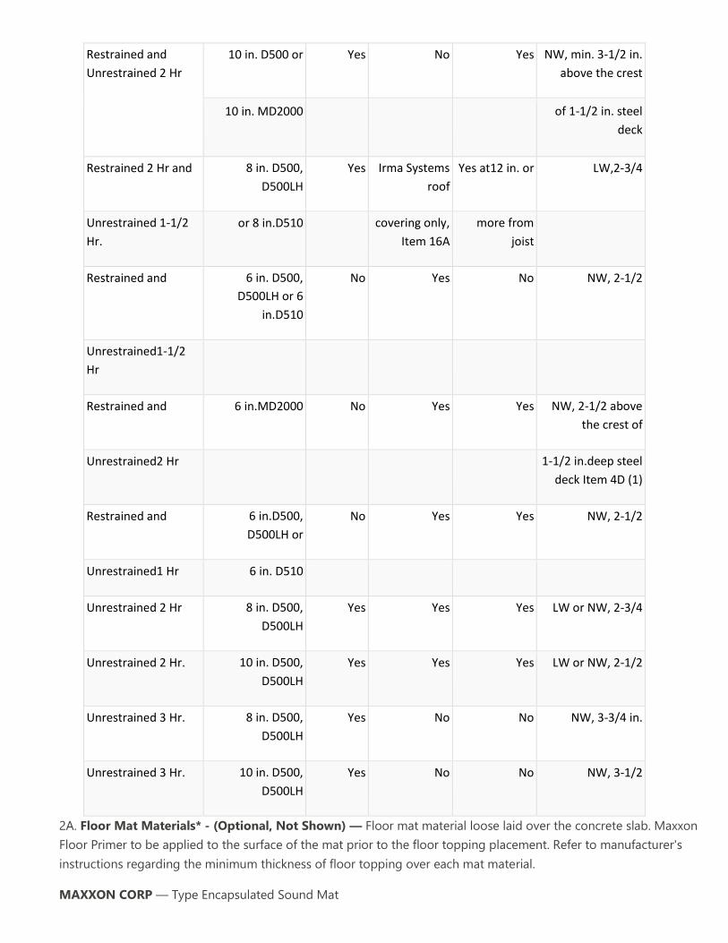
Restrained and
Unrestrained 2 Hr
10 in. D500 or Yes No Yes NW, min. 3-1/2 in.
above the crest
10 in. MD2000 of 1-1/2 in. steel
deck
Restrained 2 Hr and 8 in. D500,
D500LH
Yes Irma Systems
roof
Yes at12 in. or LW,2-3/4
Unrestrained 1-1/2
Hr.
or 8 in.D510 covering only,
Item 16A
more from
joist
Restrained and 6 in. D500,
D500LH or 6
in.D510
No Yes No NW, 2-1/2
Unrestrained1-1/2
Hr
Restrained and 6 in.MD2000 No Yes Yes NW, 2-1/2 above
the crest of
Unrestrained2 Hr 1-1/2 in.deep steel
deck Item 4D (1)
Restrained and 6 in.D500,
D500LH or
No Yes Yes NW, 2-1/2
Unrestrained1 Hr 6 in. D510
Unrestrained 2 Hr 8 in. D500,
D500LH
Yes Yes Yes LW or NW, 2-3/4
Unrestrained 2 Hr. 10 in. D500,
D500LH
Yes Yes Yes LW or NW, 2-1/2
Unrestrained 3 Hr. 8 in. D500,
D500LH
Yes No No NW, 3-3/4 in.
Unrestrained 3 Hr. 10 in. D500,
D500LH
Yes No No NW, 3-1/2
2A. Floor Mat Materials* - (Optional, Not Shown) — Floor mat material loose laid over the concrete slab. Maxxon
Floor Primer to be applied to the surface of the mat prior to the floor topping placement. Refer to manufacturer's
instructions regarding the minimum thickness of floor topping over each mat material.
MAXXON CORP — Type Encapsulated Sound Mat

Floor Mat Reinforcement (Optional) — Refer to manufacturer's instructions regarding minimum thickness of floor
topping for use with floor mat reinforcement.
Metal Lath Reinforcement — (Optional)— 3/8 in. expanded galvanized steel diamond mesh, 3.4 lbs./sq. yd loose laid
over the floor mat material.
Fiber Glass Reinforcement — (Optional) - 0.015 in. thick PVC coated non-woven fiberglass mesh, 0.368 lbs./sq. yd
loose laid over the floor mat material
Finish Flooring - Floor Topping Mixture* - Min 3/4 in. thickness of floor topping having a minimum compressive
strength of 1500 psi. Refer to manufacturer's instructions accompanying the material for specific mix design.
MAXXON CORP — Types Maxxon Standard and Maxxon High Strength
2B. Floor Mat Materials* — (Optional) - Floor mat material loose laid over the concrete slab.
MAXXON CORP — Type Encapsulated Sound Mat
Gypsum Board* — (For use when floor mat Item 2B is used) Two layers of nom 5/8 in. thick, 4 ft wide gypsum board,
installed with long dimension perpendicular to joists on top of the floor mat material. Gypsum board secured to each
other with 1 in. long No. 6 Type G bugle head steel screws spaced 12 in. OC and located a min of 1-1/2 in. from side
and end joints. The joints of the gypsum board are to be staggered a minimum of 12 inches in between layers and
from the joints of the subfloor.
GEORGIA-PACIFIC GYPSUM L L C — Type DS
2C. Floor Topping Mixture* — (Not Shown) — Optional Min 3/4 in. thickness of floor topping mixture having a
minimum compressive strength of 1800 psi. Refer to manufacturer's instructions accompanying the material for
specific mix design.
UNITED STATES GYPSUM CO — Types LRK, HSLRK, CSD
USG MEXICO S A DE C V — Types LRK, HSLRK, CSD
Floor Mat Materials* — (Optional) - Floor mat material loose laid over the subfloor. Refer to manufacturer's
instructions regarding the minimum thickness of floor topping over each floor mat material.
UNITED STATES GYPSUM CO — Types SAM, LEVELROCK® Brand Sound Reduction Board, LEVELROCK® Brand Floor
Underlayment SRM-25
2D. Alternate Floor Topping Mixture* — Compressive strength to be 3500 psi min. Minimum thickness to be 1 in. as
measured from the subfloor or the top plane of the Floor Mat Material*. Refer to manufacturer's instructions
accompanying the material for specific mix design. An ethylene vinyl acetate adhesive may be applied to the subfloor
prior to the installation of the floor topping mixture at a maximum application rate of 0.025 lbs./ft2.
HACKER INDUSTRIES INC — Firm-Fill CMD
Floor Mat Materials* — (Optional) - Floor mat material nom 5/64 in. (2 mm) thick adhered to subfloor with Hacker
Floor Primer. Primer to be applied to the surface of the mat prior to the placement of floor-topping mixture. Floor
topping thickness a min 1 in. (25 mm) over the floor mat.
HACKER INDUSTRIES INC — Hacker Sound-Mat I.
Alternate Floor Mat Materials — (Optional) —Floor mat material nom 1/4 in. (6mm) thick adhered to subfloor with
Hacker Floor Primer. Primer to be applied to the surface of the mat prior to the placement of a min 1-1/4 in. (32mm)
of floor-topping mixture.
HACKER INDUSTRIES INC — Hacker Sound-Mat II.
Alternate Floor Mat Materials — (Optional) — Floor mat material nom 1/8 in. (3mm) thick loose laid over the
subfloor. Floor topping thickness shall be a min of 1 in. (25mm)
HACKER INDUSTRIES INC — FIRM-FILL SCM 125
Alternate Floor Mat Materials — (Optional) — Floor mat material nom 1/4 in. (6mm) thick loose laid over the
subfloor. Floor topping thickness shall be a min of 1 in. (25mm)
HACKER INDUSTRIES INC — Type FIRM-FILL SCM 250
Alternate Floor Mat Materials — (Optional) — Floor mat material nom 3/8 in. (10mm) thick loose laid over the
subfloor. Floor topping thickness shall be a min of 1-1/4 in. (32mm)
HACKER INDUSTRIES INC — FIRM-FILL SCM 400
Alternate Floor Mat Materials — (Optional) — Floor mat material nom 3/4 in. (19mm) thick loose laid over the
subfloor. Floor topping thickness shall be a min of 1-1/2 in. (38mm)
HACKER INDUSTRIES INC — FIRM-FILL SCM 750
2E. Floor Topping Mixture* — (Optional, Not Shown) — Min 3/4 in. thickness of floor topping having a minimum
compressive strength of 1500 psi. Refer to manufacturer's instructions accompanying the material for specific mix
design.
FORMULATED MATERIALS LLC — Types FR-25, FR-30, and SiteMix.

Floor Mat Materials* — (Optional) — Floor mat material loose laid over the concrete slab. Refer to manufacturer's
instructions regarding the minimum thickness of floor topping over each floor mat material.
FORMULATED MATERIALS LLC — Types M1, M2, M3, Elite, Duo, R1, and R2.
2F. As an alternate to Items 2 - 2E:
Vapor Barrier — (Optional) - Commercial asphalt saturated felt, 0.030 in. thick.
Vapor Barrier — (Optional) - Nom 0.010 in. thick commercial rosin-sized building paper.
Finish Flooring - Floor Topping Mixture* — Min 3/4 in. thickness of any Floor Topping Mixture bearing the UL
Classification Marking as to Fire Resistance. See Floor- and Roof-Topping Mixtures (CCOX) category for names of
Classified Companies.
Floor Mat Materials* — (Optional, Not Shown) - Floor mat material loose laid over the subfloor. Refer to
manufacturer's instructions regarding the minimum thickness of floor topping over each floor mat material.
LOW & BONAR INC — EnkaSonic® by Colbond a member of the Low & Bonar group Types 125, 250, 250 Plus, 400,
400 Plus, 750, and 750 Plus.
Floor Mat Reinforcement — (Optional) - Refer to manufacturer's instructions regarding minimum thickness of floor
topping for use with floor mat reinforcement.
Metal Lath — (Optional) — Expanded steel diamond mesh, 2.5 lb / sq yd loose laid over floor mat material.
Fiberglass Mesh Reinforcement — (Optional) — Coated non-woven glass fiber mesh grid loose laid over floor mat
material.
3. Welded Wire Fabric — Min. 6 x 6 — W2.1 x W2.1, or as required by the latest ACI code.
3A. Fiber Reinforcement* — (For use with Item 4C only) As an alternate to Item 3, for 1, 1-1/2 and 2 hr assembly and
beam ratings only. Engineered Synthetic or Steel fibers added to concrete mix to control shrinkage cracks in concrete.
See Fiber Reinforcement (CBXQ) Category for rate that fibers are added to concrete mix and names of manufacturers.
The floor assembly with the fiber reinforcement must still meet its structural capacity requirements.
4. Structural Steel Members* — Composite steel joists, min nom depth 6 in. Spaced 49-1/4 in. OC (to accommodate
4 ft wide forms) or max 52 in. OC (when steel form units, Item 4A are used). Minimum nom. depth of 10 in. when used
with Item 14. For 1-1/2 and 2 Hr ratings, joists may also be spaced as follows:
a. 6 ft, 0 in. OC max when flanked on both sides by 49-1/4 in. spans.
b. 6 ft, 0 in. OC max when flanked on one side by a 37-1/4 in. span and on the other by a 61-1/4 in. span.
c. 5 ft, 0 in. OC max when flanked on one side by a 61-1/4 in. span and on the other by a 44-1/4 in. span.
d. 4 ft, 8 in. OC max when flanked on both sides by 4 ft, 9-1/4 in. spans.
e. 5 ft, 6 in. OC max when flanked on one side by a 49-1/4 in. span and on the other by a 55-1/4 in. span.
f. 5 ft, 4 in. OC max when flanked on both sides by 49-1/4 in. spans.

HAMBRO STRUCTURAL SYSTEMS, DIV OF CANAM STEEL CORP — Type D510, D500LH or D500.
As alternates to the D500 or D510 joists, mini joists designated TC and RTC may be used for max spans of 5 ft
0 in. and 8 ft 0 in., respectively.
4A. Steel Form Units — (Optional, Not Shown) - Not for use in 3 Hr Rated Assembly. Nom 5/8 in. deep. corrugated
steel form units nom 2 1/2 in. pitch, 28 gauge galv, painted or uncoated. For floors employing steel form units,
concrete thickness is measured from the top of the form units.
4B. Permanent Roll Bars — (Optional, Not Shown) - Installed perpendicular to joists to support corrugated steel
forms, Item 4A. Hat-shaped steel section, 1/2 in. wide, 2 or 2-1/2 in. deep, 18 gauge steel. Ends engaged into slots
near top of joists, spaced max 30 in. O. C.
4C. Structural Steel Members* — (Not Shown) — As an alternate to Items 4, 4A, 4B, the following components may
be used:
(1) Steel Floor and Form Units — Min 9/16 in. deep, 28 gauge uncoated or galv fluted steel floor units. The
steel deck used only as a form and shall not be considered in calculating the load carrying capacity of the
floor.
(2) Welded Wire Fabric/Reinforcing Bars — As required to develop the structural capacity of the floor in
accordance with the applicable ACI specifications.
(3) Structural Steel Members* — Hambro joists, min nom depth 6 in., or min. nom. depth 10 in. when used
with Item 14, spacing 52 in. OC or spaced as follows:
(a) 6 ft, 0 in. max when flanked on both sides with 48 in. spans.
(b) 6 ft, 0 in. max when flanked on one side by a 37-1/4 in. span and on the other by a 60 in. span.
(c) 5 ft, 0 in. when flanked on one side by 60 in. span and on the other by 44 in. span.
(d) 4 ft, 8 in. when flanked on both sides by 4 ft - 9-1/4 in. spans.
(e) 5 ft, 6 in. when flanked on one side by 48 in. span and on the other by 54 in, span.
(f) 5 ft, 4 in. when flanked on both sides by 48 in spans.
(g) 5 ft, 10 in. 0C continuous three spans may be used only for max 1-1/2 hr ratings.
HAMBRO STRUCTURAL SYSTEMS, DIV OF CANAM STEEL CORP — Type MD2000. As alternates to MD2000
joists, mini joists designated MD and RMD may be used for 5 ft 0 in. and 8 ft. 0 in., respectively.
Min concrete slab thickness, as measured from the top of the steel floor units, is 2-1/2 in. with min 1 in.
concrete cover above the top elevation of the top chord for all Restrained and Unrestrained Assembly
Ratings.
4D. Structural Steel Members* — (Not Shown) — As an alternate to Items 4, 4A, 4B, 4C, the following components
may be used for a 1-1/2 hour Restrained and Unrestrained rating:
(1) Steel Floor and Form Units — Min 1-1/2 in. deep, 22 gauge uncoated or galv fluted steel floor units
attached to the flange of the steel joists with No. 10, 3/4 in. long self tapping screws spaced a maximum of 36
in. OC.
(2) Welded Wire Fabric/Reinforcing Bars — As required to develop the structural capacity of the floor in
accordance with the applicable ACI specifications.
(3) Structural Steel Members* — Hambro joists, min nom depth 10 in., spaced a maximum 6 ft. OC.
HAMBRO STRUCTURAL SYSTEMS, DIV OF CANAM STEEL CORP — Type MD2000.
Min concrete slab thickness, as measured from the top of the steel floor units, is 2-3/4 in. with min 1-1/4 in.
concrete cover above the top elevation of the top chord for all Restrained and Unrestrained Assembly
Ratings.
5. Tie Wire — No. 18 SWG (0.048 in. diam) galv steel wire. Tie wire used to attach wallboard furring channels to steel
joists or cold rolled channels.
5A. Hanger Wire — (Not Shown), For use with Steel Framing Members No. 12 SWG galv steel wire spaced a max of 48
in. OC. on main runners. Twist-tied to bottom chord of joists and to hanger wire hole closest to the joist (in the web of
main runner), to minimize splaying of wires. Additional hanger wires required at center of cross tees adjacent to air
duct outlets.
5B. Hanger Clips — (Not shown) Galv steel angles, 3/4 in. long with 1-3/8 in. horizontal and 1 in. vertical legs. Vertical
leg provided with a 5/16 in. diam hole to accommodate hanger wire. Horizontal leg provided with a 3/16 in. diam hole
for insertion of fastener. Hanger clips secured to underside of concrete slab using nom 1 1/8 in. long, 0.145 in. diam
shank with 0.312 in. diam head, powder-driven galv steel fasteners.
5C. Steel Framing Members — (As an alternate to Item 5B) (Not evaluated for use with items 10E - 10T) - Concrete
anchor assembly to provide alternate method to attach hanger wire (Item 5A). Anchor consists of galvanized steel
angle, 1-7/16 in. by 1-5/16 in. by 1-3/16 in. long, which are secured within pre-drilled holes in the underside of the
concrete slab through a rubber grommet and anchor system. The galvanized angle includes holes to accommodate tie
wire (Item 5) which is twist-tied around the cold rolled channels at the other end. Hanger clips are to be spaced
maximum 48 in. OC.
SOPREMA INC — Acoustivibe CDC
5D. Steel Framing Members — (As an alternate to Item 5B and 5C) (Not evaluated for use with items 10E - 10T) -
Concrete anchor assembly to provide alternate method to attach hanger wire. Anchor consists of galvanized steel
angles, 1-7/16 in. by 1-5/16 in. by 1-3/16 in. long, which are secured to Steel Floor and Form Units (Item 4A and 4C.1)
prior to pouring of concrete topping. This anchor is not to be used in the absence of Steel Floor and Form Units (Item
4A or 4C.1). Anchors consist of a rubber grommet, galvanized angle, washers, and self-tapping fastener which
penetrate Steel Floor and Form Unit. Fastener used for anchor is to be minimum 2-3/16 in. long, with 1-1/4 in.
penetrating into the Steel Floor and Form Units and concrete topping. The galvanized angle includes holes to
accommodate tie wire (Item 5) which is twist-tied around the cold rolled channels at the other end. Hanger clips are to
be spaced maximum 48 in. OC.
SOPREMA INC — Acoustivibe NAS
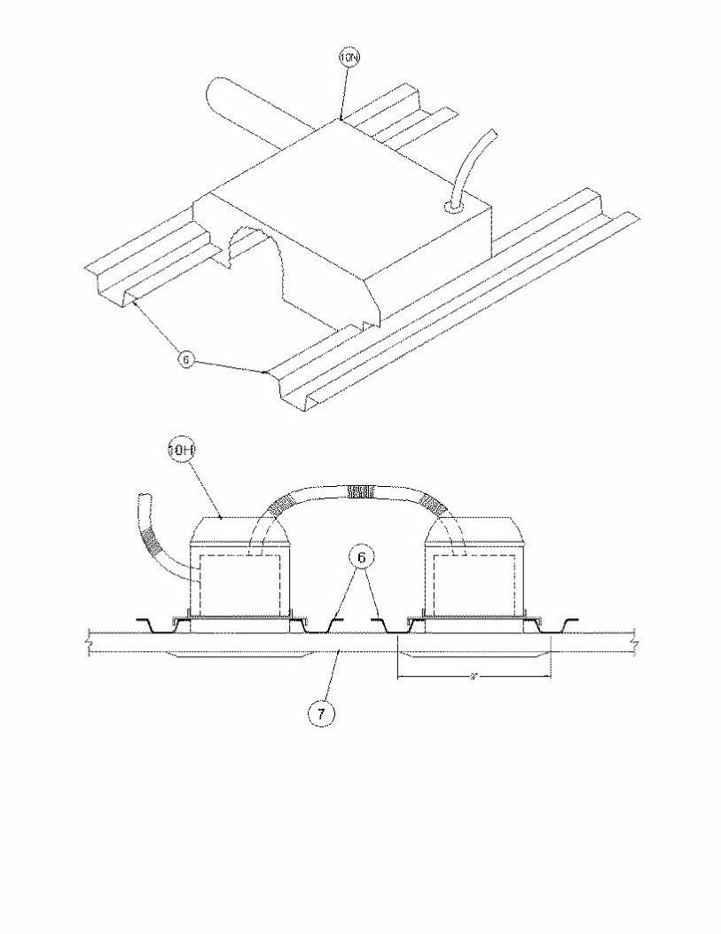
6. Furring Channels — 25 gauge or heavier, galv steel, 7/8 in. high, 2-5/8 in. or 2-9/16 in. or 2-23/32 in. base width, 1-
3/8 in. face width and 12 ft long. Installed perpendicular to steel joists 24 in. OC when used with Gypsum Board, Item 7
and 16 in. OC when use with Gypsum Board, Item 7A or 7B. When structural steel members from Item 4C (3) are
employed, the furring channels shall be spaced 16 in. OC for the 2 hr Restrained and Unrestrained assembly rating and
24 in. OC for the 1-1/2 hr unrestrained assembly rating when wallboard in Item 7 is used. When structural steel
members from Item 4D are employed, the furring channels shall be spaced 16 in. OC. for the 1-1/2 hour Restrained
and Unrestrained assembly rating. Installed perpendicular to steel joists maximum 16 in. OC. for a 2 hour Restrained
and Unrestrained assembly rating, when Items 7C and 14 are used. At protected wallboard end joints, one channel
approx 60 in. long shall be located on each side and 3 in. from end joint. All channels tied to bottom chord of each
joist (and each intermediate support, when used) with double strand of tie wire. At splices, channels overlapped 8 in.
and tied together with double strand of tie wire near each end of overlap. As an option for maximum 1 hour ratings
(not shown) wood or fiberglass shims, 3 in. by 5 in. by maximum 1 in. thick, or wool felt pad shims, 2 in. by 4 in. by
maximum 1 in. thick, may be friction-fit between the top surface of the furring channels and the lower surface of the
structural steel members.
6A. Steel Framing Members* — (Not Shown) — For the 1, 1-1/2 and 2 Hr Assembly and Beam Ratings only, as
alternate to Furring Channels (Item 6), the following suspension system may be used:
a. Main runners — Nom. 12 ft. long spaced 4 ft OC perpendicular to steel joists.
b. Cross Tees — Nom 4 ft. long, 1-1/2 in. wide face or 15/16 in. wide face installed at sides of light fixtures,
installed perpendicular to the main runners, spaced 24 in. OC. When Batts and Blankets* (Item 13) are used,
cross tees spaced 16 in. OC. Additional cross tees or cross channels used at 8 in. from each side of butted
wallboard end joints. The cross tees or cross channels may be riveted or screw attached to the wall angle or
channel to facilitate the ceiling installation.
ROXUL USA INC. D/B/A ROCKFON — Types 650, 650C, 670, 670C.
6B. Wall Molding — (Not Shown) — For use with Items 6A or 6D , min 0.019 in. thick steel channel, 1-11/16 in. with
15/16 in. legs, nailed to walls along perimeter of ceiling.
6C. Steel Framing Members* — (Not Shown) — As an alternate to Items 6, 6A and 6B. Main runners nom 12 ft long,
spaced 48 in. OC. Cross channels, 4 ft long, installed perpendicular to main runners and spaced 24 in. OC. Additional
cross channels required 8 in. from and on each side of gypsum board end joints.
ROXUL USA INC. D/B/A ROCKFON — Types 630, 650, 650C, 670, 670C. When Type 630 Steel Framing Members or
Types 654C or 674C cross tees are used, unrestrained assembly and beam ratings are limited to 2 hr.
6D. Steel Framing Members* — As an alternate to Items 6, 6A, 6B and 6C. Main runners, cross tees, cross channels
and wall angle as listed below:
a. Main Runners — Nom 10 or 12 ft. long, 15/16 in. or 1-1/2 in. wide face, spaced 4 ft. OC.

b. Cross Tees — Nom 4 ft. long, 1-1/2 in. wide face or 15/16 in. wide face installed at sides of light fixtures,
installed perpendicular to the main runners, spaced 24 in. OC. When Batts and Blankets* (Item 13) are used,
cross tees spaced 16 in. OC. Additional cross tees or cross channels used at 8 in. from each side of butted
wallboard end joints. The cross tees or cross channels may be riveted or screw attached to the wall angle or
channel to facilitate the ceiling installation.
c. Cross Channels — Nom 4 ft. long, installed perpendicular to main runners, spaced 24 in. OC. When Batts
and Blankets* (Item 13) are used, cross channels spaced 16 in. OC.
d. Wall Angle or Channel — Painted or galv steel angle with 1 in. legs or channel with 1 in. legs, 1-9/16 in.
deep attached to walls at perimeter of ceiling with fasteners 16 in. OC. To support steel framing member ends
and for screw-attachment of the gypsum board .
CGC INC — Type DGL or RX.
USG INTERIORS LLC — Type DGL or RX.
6E. Steel Framing Members* — (Not shown) - As an alternate to Items 6, 6A, 6C and 6D, main runners nom 12 ft
long, spaced 48 in. OC. Ends of main runners at walls to rest on wall molding (Item 6B), without attachment, with 1/2
to 3/4 in. end clearance. Primary cross tees (1-1/2 in. wide across flange) or cross channels, nom 4 ft long, installed
perpendicular to main runners and spaced 24 in. OC. Additional primary cross tees or cross channels required at each
gypsum board end joint and 8 in. from and on each side of gypsum board end joint.
ARMSTRONG WORLD INDUSTRIES INC — Type DFR-8000
6F. Steel Framing Members* — (Optional, Not Shown, Not evaluated for use when Items 10E - 10T are used) —
Alternate method to attach furring channels (Item 6) to joists (Item 4) or cold rolled channels (item 6J). Clips spaced 48
in. OC., and secured to consecutive joists or cold rolled channels with cup washer installation kit provided by
manufacturer. On underside of bottom chord, 1-1/2 in. dia x 3/8 in. deep No. 16 galv steel cup washer is placed to
surround the rubber insert. Clip attached to the bottom chord with a 1/4 in. dia. zinc plated bolt inserted through the
center grommet and between the chord members; depth of bolt determined as 2 in. plus the depth of the bottom
chord of the joist. Fastened on the top side of the bottom chord with a second cup washer placed open side down,
and a 1/4 in. zinc plated "Nyloc" nut. When used with cold rolled channels (item 6J), clips are screw-attached to the
channels with minimum No. 8 x 1-1/2 in. self-drilling, self-tapping screws. The 1-1/2 in. dia x 3/8 in. deep No. 16 galv
steel cup washer is placed between the clip and the cold rolled channels. Furring channels are friction fitted into clips.
RSIC-1 clip for use with 2-9/16 in. wide furring channels. RSIC-1 (2.75) clip for use with 2-23/32 in. wide furring
channels. Ends of adjoining channels are overlapped 6 in. and tied together with double strand of No. 18 SWG galv
steel wire near each end of overlap. As an alternate, ends of adjoining channels may be overlapped 6 in. and secured
together with two self-tapping No. 6 framing screws, min. 7/16 in. long at the midpoint of the overlap, with one screw
on each flange of the channel. Additional clips required to hold furring channel that supports the gypsum board butt
joints, as described in Item 7. When the composite steel joists are spaced more than 52 in. OC, a cold-rolled steel
channel shall be used as specified in Item 6I, except the channel shall be min. 16 gauge, 1-1/2 in. deep with 1 in.

flanges and the channel shall only be suspended with its lower flange flush with the plane at the bottom of the joists.
Clips to be screw-attached to every channel with minimum No. 8 x 1-1/2 in. self-drilling and self-tapping screws to the
cold-rolled channel and with a 1-1/2 in. dia x 3/8 in. deep No. 16 galv steel cup washer between the clip and cold-
rolled channel as provided by manufacturer. When Fiber, Sprayed* (Item 13A) is used, two layers of gypsum board
shall be installed as described in Item 7.
PAC INTERNATIONAL L L C — Types RSIC-1, RSIC-1 (2.75).
6G. Steel Framing Members* — (Not Shown) —As an alternate to Items 6, 6A, 6B, 6C, 6D, 6E and 6F. For use in
corridors or rooms having a maximum width dimension of 14 ft. Steel framing members consist of grid runners,
locking angle wall molding and hanger bars. Locking angle wall molding secured to walls with steel nails or screws
spaced max 24 in. OC. Slots of locking angle wall molding parallel with hanger bars to be aligned with tabbed cutouts
in bottom edge of hanger bars. Hanger bars spaced max 50 in. OC and suspended with No. 12 AWG steel hanger
wires spaced max 48 in. OC. Adjoining lengths of hanger bar to overlap 12 in. and to be secured together and
suspended by a shared hanger wire. A min clearance of 1/4 in. shall be maintained between the ends of the hanger
bars and the walls. Grid runners cut-to-length and installed perpendicular to hanger bars and spaced max 24 in. OC
with additional grid runners installed 8 in. OC at gypsum board end joints. Grid runners parallel with walls to be
spaced max 16 in. from wall. Ends of grid runners to rest on and engage slots of locking angle wall molding with a
clearance of 3/8 in. to 1/2 in. maintained between each end of the grid runner and the wall. Bulb of grid runner to be
captured by tabbed cutouts in bottom edge of hanger bars.
ARMSTRONG WORLD INDUSTRIES INC — Type DFR-8000-SS. When Type DFR-8000-SS Steel Framing Members
are used, assembly and beam ratings are limited to 2 hr.
6H. Steel Framing Members* — (Not Shown) — As an alternate to Items 6, 6A, 6B, 6C, 6D, 6E, 6F and 6G. Main
runners nom 12 ft long, spaced 72 in. OC. Cross tees, nom 6 ft long, installed perpendicular to main runners and
spaced 24 in. OC. Additional 6 ft long cross tees required at each gypsum board end joint with butted gypsum board
end joints centered between cross tees spaced 8 in. OC. The main runners and cross tees may be riveted or screw-
attached to the wall angle or channel to facilitate the ceiling installation.
ARMSTRONG WORLD INDUSTRIES INC — Type DFR-8000. When Type DFR-8000 Steel Framing Members with 6
ft long cross tees are used, assembly and beam ratings are limited to 2 hr.
6I. Cold Rolled Channels — (Not shown) - Min 0.045 in. thick (18 gauge) cold-rolled steel channels, 1-1/2 in. deep
with 7/16 in. flanges. When the composite steel joists are spaced more than 52 in. OC, a cold-rolled steel channel shall
be suspended midway between joists, with its web vertical and with its lower flange flush with the plane at the bottom
of the joists, to provide an intermediate support for the furring channels (Item 6). The cold-rolled channels are
suspended from hanger clips (Item 5B) using 12 SWG galv steel hanger wire spaced max 50 in. OC. When Item 4D, 6,
7B, and 13 are employed for the 1-1/2 hour Restrained and Unrestrained rating, the 12 SWG galv. steel hanger wire is
spaced a maximum 48 in. OC. Adjoining lengths of cold-rolled channel spliced together by overlapping min 12 in.,
face to face or back to back, and tying with three double strands of 18 SWG galv steel wire. When it is necessary to
lower the ceiling below the bottom plane of the joists, 1-1/2 in. deep, 16 gauge cold rolled steel channels shall be

used for attachment of furring channels. The channels shall be installed with their web oriented vertically and
suspended from the joists or from the hanger clips (Item 5B) with 12 SWG or heavier gauge hanger wire at a max
spacing of 48 in. OC. The spacing of the channels shall be no greater than the spacing of the joists.
6J. Cold Rolled Channels — (Not shown) - 1-1/2 in. cold rolled steel channels made of min. 16 gauge painted or
galvanized steel. Channel web oriented vertically, positioned beneath and parallel or perpendicular to the structural
steel members. Channels spaced not more than the spacing of the structural steel members (Item 4). Channels
supported by min No. 12 gauge galvanized steel wire spaced a maximum of 48 in. OC.
6K. Steel Framing Members* — (Optional, Not Shown, Not evaluated for use with Items 10E-10T) — Use as an
alternate method to attach 2-5/8 in. base width furring channels (Item 6) to joists (Item 4). Clips spaced 48 in. OC., and
secured to alternating joists with cup washer installation kit provided by manufacturer. GenieClip clip attached to the
bottom chord with a 1/4 in. dia. zinc plated bolt inserted through the center grommet and between the chord
members; depth of bolt determined as 2 in. plus the depth of the bottom chord of the joist. Furring channels are
friction fitted into clips. Ends of adjoining channels are overlapped 6 in. and tied together with double strand of No. 18
SWG galv steel wire near each end of overlap. Additional clips required to hold furring channel that supports the
wallboard butt joints, as described in Item 7. When the composite steel joists are spaced more than 52 in. OC, a cold-
rolled steel channel shall be used as specified in Item 6I, except the channel shall be min. 16 gauge, 1-1/2 in. deep with
1 in. flanges and the channel shall only be suspended with its lower flange flush with the plane at the bottom of the
joists. GenieClips clips to be screw-attached to every channel with 1/4 in. dia. zinc plated bolt inserted through the
center grommet and between the chord members; depth of bolt determined as 2 in. plus the depth of the bottom
chord of the joist.
PLITEQ INC — Type GenieClip
6L. Steel Framing Members* — (Optional, Not Shown, Not evaluated for use with Items 10E-10T) - Used as an
alternate method to attach furring channels (item 6) to joists (item 4). Clips spaced at 48" OC and secured to
consecutive joists or cold rolled channels with cup washer installation kit provided by manufacturer. On underside of
bottom chord, 1-1/2 in. dia x 3/8 in. deep No. 16 galv steel cup washer is placed to surround the rubber insert of clip.
Clip attached to the bottom chord with a 1/4 in. dia zinc plated bolt inserted through the center grommet and
between the chord members; depth of bolt determined as 2 in. plus the depth of the bottom chord of the joist.
Fastened on the top side of the bottom chord with a second cup washer placed open side up, and a 1/4 in. zinc plated
"Nyloc" nut. When used with cold rolled channels (item 6J), clips are screw-attached to the channels with minimum
No. 8 x 1-1/2 in. self-drilling, self-tapping screws. The 1-1/2 in. dia x 3/8 in. deep No. 16 galv steel cup washer is
placed between the clip and the cold rolled channels. Furring channels are then friction fitted into clips. Ends of
channels are overlapped 6" and tied together with double strand of No. 18 AWG galvanized steel wire.Additional clips
are required to hold the Gypsum Butt joints as described in item 7. When the composite steel joists are spaced more
than 52 in. OC, a cold-rolled steel channel shall be used as specified in Item 6I, except the channel shall be min. 16
gauge, 1-1/2 in. deep with 1 in. flanges and the channel shall only be suspended with its lower flange flush with the
plane at the bottom of the joists. Clips to be screw-attached to every channel with minimum No. 8 x 1-1/2 in. self-
drilling and self-tapping screws to the cold-rolled channel and with a 1-1/2 in. dia x 3/8 in. deep No. 16 galv steel cup
washer between the clip and cold-rolled channel as provided by manufacturer.
STUDCO BUILDING SYSTEMS — RESILMOUNT Sound Isolation Clips - Type A237R

6M. Steel Framing Members* — (Not Shown) - As an alternate to Items 6 through 6L - Main runners nom 12 ft long,
spaced 72 in. OC. Cross tees, nom 6 ft long, installed perpendicular to main runners and spaced 24 in. OC. Additional 6
ft long cross tees required at each gypsum board end joint with butted gypsum board end joints centered between
cross tees spaced 8 in. OC. The main runners and cross tees may be riveted or screw attached to the wall angle or
channel to facilitate the ceiling installation.
USG INTERIORS LLC — Type DGL or RX. When Type DGLor RX Steel Framing Members with 6 ft long cross tees
are used, assembly and beam ratings are limited to 2 hr.
6N. Alternate Steel Framing Members — (Not Shown) - As an alternate to Items 6 through 6M - Main runners nom
12 ft long, spaced 48 in. OC. Cross tees, nom 4 ft. long, installed perpendicular to main runners and spaced 24 in. OC.
Additional 4 ft. long cross tees required at 6 in. from each side of butted gypsum board end joints. When Batts and
Blankets* (Item 13) are used, cross tees spaced 16 in. OC with additional cross tees 8 in. away from each side of
butted gypsum board end joints. The cross tees shall be riveted with 1/8 in. dia. rivets to the wall angle and to the
main tee where the cross tee does not align with slot in the main tee. Galvanized steel wall angle with 1-1/2 in. legs
attached to walls at perimeter of ceiling with fasteners at 16 in. OC. to support steel framing member ends and for
screw-attachment of the gypsum board.
CERTAINTEED CORP — Types DWS12-13-20, DWS4.16-13-20, DWS4-13-20, DWS2-13-20, DWS2.16-13-20 and
DWA1.5-1.5. When Type DWS Steel Framing Members are used, assembly and beam ratings are limited to 2 hr.
6O. Framing Members* — (Not Shown) — As an alternate to Items 6 through 6N. Main runners nom 12 ft long,
spaced 72 in. OC. Main runners suspended by min 12 SWG galv steel hanger wires spaced 48 in. OC. Cross tees, nom 6
ft long, installed perpendicular to main runners and spaced 24 in. OC. Additional 6 ft long cross tees required at each
gypsum board end joint with butted gypsum board end joints centered between cross tees spaced 8 in. OC. The main
runners and cross tees may be riveted or screw attached to the wall angle or channel to facilitate the ceiling
installation.
ROXUL USA INC. D/B/A ROCKFON — Type 670C
7. Gypsum Board* — 1/2 or 5/8 in. thick, 4 ft wide installed with long dimension perpendicular to furring channels
and side joints located between joists. End joints in adjacent rows to be staggered min of 2 ft. Unless otherwise
specified in Item 2, end joints shall be protected with a 3 in. wide strip of wallboard to be inserted for entire length of
end joint between the two furring channels. When the end joint occurs within 12 in. of the steel beam, it must be
protected. No. 6 Phillips-type, self-drilling and self-tapping, 1-1/4 in. long with bugle head screws spaced a max 12 in.
OC fastening the wallboard to furring channels. At protected end joints, screws located 3 in. on each side of joint.
Along side joints, screws located 3/4 in. from board edge. One additional screw driven through the boards adjacent to
the end joint approx 1-1/2 in. from the side joint into each end of the short channels. Along side joints, fasteners
located 3/4 in. from board edge. For end joints that do not need protection, the screws shall be located 1/2 inch from
the board edge.
For use with Item 6A only — 1/2 in. thick, 4 ft wide; installed with long dimension perpendicular to cross tees with side
joints centered along main runners. Gypsum board fastened to each cross tee with five gypsum board screws (No. 6

Phillips-type, self-drilling and self-tapping) with one screw located at the midspan of the cross tee, one screw located
12 in. from and on each side of the cross tee midspan and one screw located 1-1/2 in. from each gypsum board side
joint. Except at gypsum board end joints, screws shall be located on alternating sides of cross tee flange. At gypsum
board end joints screws shall be located 1/2 in. from the joint. Gypsum board fastened to main runners with screws
located 1/2 in. from side joints midway between intersections with cross tees (24 in. OC). End joints of the gypsum
board sheets shall be staggered with joints in adjacent gypsum board courses not less than 4 ft OC. Gypsum board
sheets screw-attached to flange of wall molding with screws spaced 12 in. OC.
When alternate Steel Framing Members* (Item 6C, 6D or 6E ) are used, gypsum board installed with long dimension
(side joints) perpendicular to the cross channels and 4 ft cross tees and with the side joints centered along the main
runners. Gypsum board fastened to cross channels with gypsum board screws located 1/2 in. from butted end joints,
with one screw located at the midspan of the cross channel, one screw located 12 in. from and on each side of the
channel mid span, and one screw located 2-3/4 in. from each side joint. from each side joint. End joints of the sheets
shall be staggered as described above.
When alternate Steel Framing Members* (Item 6F ) are used, gypsum board butt joints shall be staggered min. 2 ft.
within the assembly, and occur between the main furring channels. Edge joints may occur beneath the joists. At the
gypsum board butt joints, each end of the gypsum board shall be supported by a single length of furring channel
equal to the width of the gypsum board plus 6 in. on each end. The furring channels shall be spaced approximately 3-
1/2 in. OC, and be attached to underside of the joist with one RSIC-1 clip at each end of the channel. Gypsum board
attached to the furring channels using 1 in. long Type S bugle-head steel screws spaced 8 in. OC along butted end
joints and 12 in. OC in the field of the board.
When both Steel Framing Members* (Item 6F) and Fiber, Sprayed* (Item 13A) are used, furring channels spaced 16
in. OC max. and two layers of gypsum board are installed with long dimension perpendicular to furring channels. Base
layer secured to furring channels with nom 1 in. long Type S bugle head screws spaced 8 in. OC along butted end
joints and 12 in. OC in the field of the board. Butted end joints shall be staggered min. 2 ft within the assembly, and
occur midway between the continuous furring channels. Each end of each gypsum board shall be supported by a
single length of furring channel equal to the width of the gypsum board plus 6 in. on each end. The two support
furring channels shall be spaced approximately 3-1/2 in. OC, and be attached to the underside of the truss with one
RSIC-1 clip at each end of the channel. Outer layer secured to furring channels using 1-5/8 in. long Type S screws
spaced 8 in. OC and 1-1/2 in. from the end joint. Butted end joints to be offset a min. of 8 in. from base layer end
joints. Butted side joints of outer layer to be offset min. 18 in. from butted side joints of base layer.
When alternate Steel Framing Members* (Item 6G) are used, gypsum board sheets installed with long dimension
(side joints) perpendicular to the grid runners with the end joints staggered min 4 ft and centered between grid
runners which are spaced 8 in. OC. Prior to installation of the gypsum board sheets, backer strips consisting of nom 7-
3/4 in. wide by 48 in. long pieces of gypsum board are to be laid atop the grid runner flanges and centered over each
butted end joint location. The backer strips are to be secured to the flanges of the grid runners at opposite corners of
the backer strip to prevent the backer strips from being uplifted during screw-attachment of the gypsum board sheets.
Gypsum board fastened to grid runners with 1 in. long Type S bugle head screws spaced 1 in. and 4 in. from the side
joints and max 8 in. OC in the field of the board. The butted end joints are to be secured to the backer strip with No.
10 by 1-1/2 in. long Type G laminating screws located 1 in. from each side of the butted end joint and spaced 1 in. and
4 in. from the side joints and max 8 in. OC in the field of the board.
When alternate Steel Framing Members* (Item 6H) are used, gypsum board sheets installed with long dimension
(side joints) perpendicular to the 6 ft long cross tees with the end joints staggered min 4 ft and centered between
cross tees which are spaced 8 in. OC. Gypsum board side joints may occur beneath or between main runners. Prior to
installation of the gypsum board sheets, backer strips consisting of nom 7-3/4 in. wide pieces of gypsum board are to
be laid atop the cross tee flanges and centered over each butted end joint location. The backer strips are to be
secured to the flanges of the cross tees at opposite corners of the backer strip to prevent the backer strips from being
uplifted during screw-attachment of the gypsum board sheets. Gypsum board fastened to cross tees with drywall
screws spaced 1 in. and 4 in. from the side joints and max 8 in. OC in the field of the board. The butted end joints are
to be secured to the backer strip with No. 10 by 1-1/2 in. long Type G laminating screws located 1 in. from each side
of the butted end joint and spaced 1 in. and 4 in. from the side joints and max 8 in. OC in the field of the board.

When Steel Framing Members (Item 6K) are used, 4 ft wide gypsum board is installed with long dimensions
perpendicular to furring channels. Gypsum board secured to furring channels with 1 in. long No. 6 Type S bugle-head
steel screws spaced 12 in. OC in the field of the board. Gypsum board butted end joints shall be staggered minimum
16 in. within the assembly. . At the gypsum board butt joints, each end of each gypsum board shall be supported by a
single length of furring channel equal to the width of the gypsum board plus 6 in. on each end. These additional
furring channels shall be attached to underside of the truss with Genie clips as described in Item 6K. Screw spacing
along the gypsum board butt joint shall be 6 in. OC.
When Steel Framing Members (Item 6L) are used, gypsum board is installed with long dimensions perpendicular to
furring channels. Gypsum board secured to furring channels with nom 1 in. long Type S bugle-head steel screws
spaced 8 in. OC in the field of the board. Gypsum board butted end joints shall be staggered minimum 48 in. and
centered over main furring channels. At the gypsum board butt joints, each end of each gypsum board shall be
supported by a single length of furring channel equal to the width of the gypsum board plus 3 in. on each end. The
two supporting furring channels shall be spaced approximately 3 in. in from end joint. Screw spacing along the
gypsum board butt joint and along both additional furring channels shall be 8 in. OC. Butt joint furring channels shall
be attached with a RESILMOUNT Sound Isolation Clip at each end of the channel.
When alternate Steel Framing Members* (Item 6M and 6O) are used, gypsum board sheets installed with long
dimension (side joints) perpendicular to the 6 ft long cross tees with the end joints staggered min 4 ft and centered
between cross tees which are spaced 8 in. OC. Gypsum board side joints may occur beneath or between main runners.
Prior to installation of the gypsum board sheets, backer strips consisting of nom 7-3/4 in. wide pieces of gypsum
board are to be laid atop the cross tee flanges and centered over each butted end joint location. The backer strips are
to be secured to the flanges of the cross tees at opposite corners of the backer strip with hold down clips to prevent
the backer strips from being uplifted during screw-attachment of the gypsum board sheets. Gypsum board fastened
to cross tees with 1 in. drywall screws spaced 1 in. and 4 in. from the side joints and max 8 in. OC in the field of the
board. The butted end joints are to be secured to the backer strip with No. 10 by 1-1/2 in. long Type G laminating
screws located 1 in. from each side of the butted end joint and spaced 1 in. and 4 in. from the side joints and max 8 in.
OC in the field of the board.
AMERICAN GYPSUM CO — Type AG-C
CABOT MANUFACTURING ULC — Type C
CERTAINTEED GYPSUM INC — Type FRPC or SF3 EGRG or Type C
CGC INC — Types C, IP-X2, IPC-AR, WRC, ULIX
CONTINENTAL BUILDING PRODUCTS OPERATING CO, L L C — Type LGFC-C/A.
GEORGIA-PACIFIC GYPSUM L L C — Types 5, C, DAP, DA, DAPC, TG-C.

NATIONAL GYPSUM CO — Type FSW-1, FSK-C, FSW-C or FSW-G.
PABCO BUILDING PRODUCTS L L C, DBA PABCO GYPSUM — Types PG-3, PG-C, Type C.
THAI GYPSUM PRODUCTS PCL — Type C
UNITED STATES GYPSUM CO — Types C, IP-X2, IPC-AR, ULIX, WRC.
USG BORAL DRYWALL SFZ LLC — Type C
USG MEXICO S A DE C V — Types C, IP-X2, IPC-AR, WRC.
7A. Gypsum Board* — For use when Batts and Blankets* (Item 13) and Steel Framing Members* (Item 6D) are
used — 5/8 in. thick, 4 ft wide; installed with long dimension perpendicular to cross tees with side joints centered
along main runners and end joints centered along cross tees. Fastened to cross tees with 1 in. long steel wallboard
screws spaced 8 in. OC in the field and 8 in. OC along end joints. Fastened to main runners with 1 in. long wallboard
screws spaced midway between cross tees. Screws along sides and ends of boards spaced 3/8 to 1/2 in. from board
edge. End joints of the sheets shall be staggered with spacing between joints on adjacent boards not less than 4 ft OC.
CGC INC — Types ULIX, C, IP-X2
UNITED STATES GYPSUM CO — Types ULIX, C, IP-X2
USG BORAL DRYWALL SFZ LLC — Type C
7B. Gypsum Board* — Rating is limited to 1-1/2 Hr. For use when Batts and Blankets* (Item 13) and Steel Framing
Members* (Item 6) are used — 5/8 in. thick, 4 ft wide; installed with long dimension perpendicular to furring channels.
The end joints were centered along the furring channels. The gypsum boards were fastened to the furring channels
with 1 in. long Type S high/low bugle head screws spaced 8 in. OC. at the perimeter with two screws located 3/4 in.

and 4 in. from the board edge; and 12 in. OC. in the field with 2 screws located 3/4 in. and 6 in. from the board edge.
End joints shall be staggered with spacing between end joints on adjacent gypsum boards not less than 4 ft. OC.
CGC INC — Types ULIX, C, IP-X2
UNITED STATES GYPSUM CO — Types ULIX, C, IP-X2
USG BORAL DRYWALL SFZ LLC — Type C
7C. Gypsum Board* — For use when Nonmetallic Plumbing System Components* (Item 14) and Nonmetallic
Plumbing System Components* (Item 10U) are used — Min. 1/2 in. thick, 4 ft wide installed with long dimension
perpendicular to furring channels and butt joints located between joists. End joints in adjacent rows to be staggered
min of 48 in. When the end joint occurs within 12 in. of the steel beam, it must be backed by a 3 in. wide strip of
gypsum board. Gypsum board fastened to the furring channels with 1 in. long Type S bugle head screws; spaced 8 in.
OC. in the perimeter with two screws located 3/4 in. and 4 in. from each board edge; and 12 in. OC. in the field with 2
screws located 3/4 in. and 6 in. from each board edge.
CGC INC — Types ULIX, C, IP-X2
UNITED STATES GYPSUM CO — Types ULIX, C, IP-X2
USG BORAL DRYWALL SFZ LLC — Type C
7D. Gypsum Board* — For use when alternate Steel Framing Members* (Item 6N) are used - 1/2 in. thick, 4 ft. wide;
installed with long dimension parallel to main runners and perpendicular to the 4 ft. long cross tees with the end joints
centered between cross tees which are spaced 6 in. OC. Sheets are attached to cross tees with screws spaced 8 in. OC
on the ends and 12 in. OC in the field with additional screws located 1-1/2 in, from the side edges. Sheets are attached
to the main tees with screws spaced 8 in. OC with additional screws located 4 in. OC from the edges. Screws on the
sides are located 1/2 in. from the side edge of the gypsum board. When Batts and Blankets* (Item 13) are used - 5/8
in. thick, 4 ft wide; installed with long dimension parallel to main runners and perpendicular to cross tees and attached
with screws spaced 8 in. OC on the ends and 8 in. OC in the field with additional screws located 1-1/2 in. from the side
edges. Sheets are attached to main tees with screws spaced 8 in. OC with additional screws located 4 in. OC from the
side edges. Screws on the sides located 3/4 in. from the side edge of the gypsum board, and screws at the end of the
gypsum board located 1/2 in. from the board ends. Joints to be covered with paper tape and joint compound.
CERTAINTEED GYPSUM INC — Type C

7E. Gypsum Board* — For the 1 h Restrained and Unrestrained Assembly and Beam Ratings only, 5/8 in. thick, 4
ft wide installed with long dimension perpendicular to furring channels and side joints located between joists. End
joints in adjacent rows to be staggered min of 2 ft. Unless otherwise specified in Item 2, end joints shall be protected
with a 3 in. wide strip of wallboard to be inserted for entire length of end joint between the two furring channels.
When the end joint occurs within 12 in. of the steel beam, it must be protected. No. 6 Phillips-type, self-drilling and
self-tapping, 1-1/4 in. long with bugle head screws fastening the wallboard to furring channels spaced a max 12 in. OC
along each furring channel. At protected end joints, screws located 3 in. on each side of joint. Along side joints, screws
located 3/4 in. from board edge. One additional screw driven through the boards adjacent to the end joint approx 1-
1/2 in. from the side joint into each end of the short channels. Along side joints, fasteners located 3/4 in. from board
edge. For end joints that do not need protection, the screws shall be located 1/2 inch from the board edge.
CERTAINTEED GYPSUM INC — Type X
CGC INC — ULIX
UNITED STATES GYPSUM CO — Types SCX, IP-X1, ULIX
8. Screws, Gypsum Board — Screws attached as specified in items 7 through 7C.
9. Joint System — (Not shown) — Paper tape embedded in joint compound over joints, and covered with two layers
of compound with edges feathered out. Gypsum board screw heads covered with two layers of compound.
10. Air Duct and Damper — (Optional, Not Shown) — Duct made of min 0.0082 in. thick (34 gauge) steel. Total area
of duct openings not to exceed 144 sq in. per 100 sq ft of ceiling area. Area of indiv duct opening not to exceed 144
sq in. Max dimension of opening 12 in. Duct supported by 1 1/2 in. deep, min 0.053 in. thick (16 gauge) cold-rolled
steel channels spaced not over 48 in. O.C. and on each side of duct opening. Channels suspended from upper chord of
joists by 12 SWG galv steel wire. Min clearance of 4 in. required between back of ceiling membrane and bottom of air
duct.
Damper made of min 0.056 in. thick (16 gauge) galv steel protected on both surfaces with 1/16 in. ceramic fiber paper.
Located over each duct outlet, attached to bottom of duct with corrosion resistant hinges and held open with
a Fusible Link (Bearing the UL Listing Mark). Damper to overlap duct outlet 1 in. min.. As an alternate, any UL
Classified Ceiling Damper covered for use in 2 Hr or longer rated assemblies. To be installed in duct drop close to the
back of ceiling per accompanying installation instructions.
For 1, 1-1/2 and 2 Hr Unrestrained Assembly and Beam Ratings only, ducts containing 5 in. diam or smaller duct drops
do not require dampers or other protection at the duct drops. Total area of unprotected duct outlets not to exceed 20
sq. in. per 100 sq ft of ceiling area. Area of ind. duct opening not to exceed 20 sq. in.
The unprotected and protected duct openings shall not be installed within the same 100 sq. ft. of ceiling area.
10A. Air Duct Materials* — (Optional, Not Shown) For the 1 h ratings with 6 in. deep or larger joists and for the 2 h
ratings with 8 in. deep or larger joists, as an alternate to Air Duct (Item 10), Rigid Air Duct Materials may be used in

accordance with their Fabrication Instructions. The duct outlet throat is positioned at the center of 24 in. long min.
0.029 in. thick (22 gauge) galv steel duct liner. These ducts are supported by min. 0.053 in. thick (16 gauge) cold-rolled
steel channels suspended from the joists by 12 SWG galv steel wire. Channels are placed directly below the steel duct
liner one on each side of the throat, and otherwise spaced 72 in. OC for ducts up to 36 in. wide, and 48 in. OC for
ducts between 36 and 60 in. wide. Additional supporting channels to be installed at a distance ranging from 3 to 6 in.
from the ends of each individual duct section. Min. clearance of 4 in. required between back of ceiling membrane and
bottom of air duct. As an alternate, the duct may be min 28 gauge galv steel, max 8 in diam, supported by metal
hanger straps attached directly to the bottom of the concrete slab with powder actuated pins. Pins, nom 1 in. long,
consisting of 0.145 in. diam smooth-finish galv steel shank with 1/4 in. diam head. Pins tightly inserted in 3/8 in. long
gear shaped plastic washers and driven into the slab through both ends of the strap.
JOHNS MANVILLE — Rigid, Class I.
KNAUF INSULATION LLC — Rigid, Class I.
OWENS CORNING — Rigid, Class I.
10B. Damper — (Not Shown) — For use with Item 10A. 25 gauge or heavier galv steel. Protected on both surfaces
with 1/16 in. ceramic fiber paper and held open with a Fusible Link (bearing the UL Listing Mark). Damper to overlap
duct outlet 1 in. min.
10C. Flexible Air Duct — (Not shown) — Optional (Bearing the UL Listing Mark), as an alternate to Item 10. Nom 8 in.
diam consisting of 0.006 in. thick vinyl coated, glass fiber reinforced fabric over helically wound 0.077 in. diam coated
spring steel wire. As an alternate, nom 6 in. diam air duct connector consisting of 0.005 in. thick vinyl coated, glass
fiber reinforced fabric over helically wound 0.071 in. diam coated spring steel wire. The flexible air duct and/or duct
connector is connected to galv steel sleeve (Item 10D) by means of a stainless steel hose clamp. Flexible air duct or
duct connector do not require dampers or other protection at ceiling penetrations.
The flexible air duct and duct connector shall be suspended from structural steel or hanger wire anchors by means of a
steel strap near the end connected to the steel sleeve (Item 10D), with the remainder of its length placed on the
ceiling furring channel or supported about 1 in. or higher above the gypsum board with additional steel straps or
hanger wires.
The total area of the flexible air duct opening shall not exceed 50.3 sq in. per each 100 sq ft of ceiling area; max
dimension of opening is 8 in. The total area of the duct connector opening shall not exceed 28.3 sq in. per each 100 sq
ft of ceiling area; max dimension of opening is 6 in. Damper is not required when flexible air duct or duct connector is
used.
As an alternate, the flexible air duct may be supported by the metal hanger straps attached directly to the bottom of
the concrete slab with powder-actuated pins. Pins, nom 1 in. long, consisting of 0.145 in. diam smooth-finish galv steel
shank with 1/4 in. diam head. Pins tightly inserted in 3/8 in. long gear-shaped plastic washers and driven into the slab
through both ends of the strap.
10D. Duct Outlet Sleeve — For use with Air Duct Materials (10A), or Flexible Air Duct or Duct Connector (Item 10C) at
openings in gypsum board ceiling. 4 in. long sleeve made from min 28 gauge galv steel for the 8 in. diam opening and
from min 30 gauge galv steel for the 6 in. diam opening. The sleeve shall be mounted between two 7/8 in. steel angles

of 26 gauge galv steel which are placed on top and overlap the adjacent furring channels about 3 in. Each angle is tied
to the two furring channels with a double strand of 18 SWG galv steel tie wire through 1/8 in. diam hole drilled in the
vertical leg of the steel angles. The sleeve is attached to each of the two angles with one 3/8 in. long Tek sheet steel
screw.
10E. Nonmetallic Pipes — (Optional) — For the 1 h floor-ceiling ratings, as an alternate to the 5 in. diam unprotected
duct outlet. Nom 2 in. and 4 in. diam Schedule 40 PVC (polyvinyl chloride) supply or drain, waste and vent piping
system. PVC pipes penetrate the ceiling runner into stud cavity of steel or structural grade lumber stud sheathed with
generic Unclassified gypsum wallboard partition. The PVC pipes are supported by hanger straps in conjunction with
steel hanger wires suspended from hanger clips, Item 5B. As an alternate the strap may be directly attached to the slab
by the powder-driven galv steel fasteners described to support the flexible air duct in Item 10C. The spacing of hanger
straps supporting the pipes shall not exceed 30 in. OC. Only one nom 4 in. diam PVC pipe and one nom 2 in. diam PVC
pipe are allowed per 100 sq ft of ceiling area. For Canadian Classifications, the Schedule 40 PVC may be replaced by
System 15 PVC manufactured by IPEX in accordance with Section B181.2 of CSA Standard B1800S1.
10F. Heating and Air Conditioning Plenum Box Outlet — (Optional) — For the 1-1/2 h ratings (1 h when combined
with Item 10M), as an alternate to the 5 in. diam unprotected duct outlet. 14 by 14 in. opening penetrating the ceiling.
Fabricated from pieces of min 26 MSG galv steel, attached together with lock seams and rivets. Finished box size 16 by
16 by 15 in. outside dimensions. Opposite sides of the box have 10 in. diam openings. The open bottom of the box
has 1 in. wide flanges at the four sides to engage into hemmed hanger bars for attaching the box to the furring
channels. Hanger bars consist of 1 in. wide plates made from No. 26 gauge galv steel, folded back to form a 5/8 in.
return at the top side, for engaging the horizontal flanges at the bottom of the plenum box outlet. The four sides and
top of the box shall be lined with 1 in. thick UL Classified fiberglass insulation weighing nom 5 pcf. The 10 in. diam
openings on two opposing sides of the box shall be provided with nom 3 in. long collars fabricated from No. 28 gauge
galv steel for connecting the box to the nom 10 in. diam flexible air ducts (Item 10G). Box and flexible air ducts
suspended directly from hanger clips (Item 5B) by hanger wires connected to hanger straps made from 1 in. wide, No.
26 MSG galv steel, spaced max 30 in. OC. As an alternate the strap may be directly attached to the slab by the
powder-driven galv steel fasteners described to support the flexible air duct in Item 10C. Only one 14 by 14 in. outlet
is allowed per 100 sq ft of ceiling area.
10G. Flexible Air Duct — (Optional) — For use with Item 10F. Bearing the UL Listing Mark. 10 in. ID, with a spirally
wound steel wire helix (0.045 in. diam wire) covered with vinyl fiber. Core covered with 1 in. thick UL Classified
fiberglass insulation weighing 1.0 pcf. Flexible air duct wrapped with outer jacketing consisting of aluminized vinyl film.
Flexible air ducts mounted on collars of box (Item 10F), attached to collars with adjustable 10-1/2 in. diam, 9/16 in.
wide hose clamp made of 0.024 in. thick stainless steel. As an alternate an adjustable 10-1/2 in. diam, 3/8 in. wide,
1/16 in. thick vinyl hose clamp may be used.
10H. Fixtures, Recessed Light — (Optional) — (Bearing the UL Listing Mark) — For the 1-1/2 h ratings (1 h when
combined with Item 10M), as an alternate to the 5 in. diam unprotected duct outlet. A max of four fixtures per 100 sq
ft of ceiling area. Fixture housing 6-1/2 in. diam, 7-1/2 in. high, made from painted or galv steel. Each fixture
supported on a base 6-1/2 in. by 9-7/8 in., made from painted or galv steel and screw-attached to the fixture by four
screws. Each fixture with trim and lens weighs 4 lb max. Short sides of the base containing tabs for engagement into
adjustable hanger bars supporting the fixture. Each fixture hanger bar screw-attached at one end to the ceiling furring
channel and at the other end to additional furring channel parallel to and at 9 in. from the ceiling furring channel.
Fixture trim 8 in. OD with a 5-1/4 in. inside diam opening to support a 5-3/8 in. diam diffused glass lens. Each fixture
may be activated with nom 1 in. diam UL Listed electrical nonmetallic tubing wired with three No. 12 AWG Type
THWN copper conductor wires or a UL Listed nonmetallic sheathed cable with three No. 12 AWG Type THWN copper
conductor wires. Installation of the glass lens trim on the recessed light fixtures are optional.

10I. Heating and Air Conditioning Plenum Box Outlet — (Optional) — For the 2 h ratings (1-1/2 h when combined
with Item 10M), as an alternate to the 5 in. diam unprotected duct outlet. 8 by 10 in. opening penetrating the ceiling.
Four sides of box formed from one 5 in. wide strip of No. 28 gauge galv steel, with ends of strip overlapping 3/4 in.
and fastened together with two 1/4 in. diam punches. The bottom 1 in. of the strip forming the box sides, bent 90 deg
to the outside of the box forming horizontal flanges around the perimeter of the box to engage into hanger bars for
supporting the box assembly. Sides of the box lined with 1 in. thick fiberglass insulation weighing nom 5 pcf.
Fiberglass lining to be supported on a 1 in. wide steel plate attached at the bottom perimeter of the box's four sides.
Top of the box fabricated from No. 28 gauge galv steel with 8 in. diam cutout at the center. Edges of the steel plate
forming the top of the box bent down around the box's side perimeter and riveted to the four sides of the box by one
rivet at the center of each side. Top of the box, except for the 8 in. cutout, also lined with 1 in. thick UL Classified
fiberglass insulation, weighing 5 pcf. Top insulation lining, having 8 in. diam cutout at the center, bears along its
perimeter on the 1 in. thick fiberglass lining at the box sides. The 8 in. diam cutout at the top of the box connected to
a 4 in. long, 8 in. diam sleeve made from No. 28 gauge galv steel for top mounting of an 8 in. flexible air duct (Item
10J). Flexible air duct suspended by a hanger wire from hanger clip (Item 5B), connected to a nom 1 in. wide, No. 26
MSG galv steel plumbing strap wrapped around the flexible air duct near its connection to the box. As an alternate the
strap may be directly attached to the slab by the powder-driven galv steel fasteners described to support the flexible
air duct in Item 10C.
The 8 x 10 plenum box outlet, with the fiberglass top insulation, without the steel top cover, may be used for the 1 h
ratings as an alternate to the 5 in. diam unprotected duct outlet.
Only one 8 by 10 in. box outlet is allowed per 100 sq ft of ceiling area.
10J. Flexible Air Duct — (Optional) — (Bearing the UL Listing Mark) — For use with (Item 10I or Item 10P). For use
with Item 10I, nom 8 in. diam, consisting of 0.005 in. thick vinyl-coated reinforced fiberglass fabric, wrapped over
helically wound 0.038 in. diam coated spring steel wire. Flexible air duct attached to box sleeve with adjustable 8-1/2
in. diam, 9/16 in. wide hose clamp made from 0.024 in. thick stainless steel. As an alternate an 8-1/2 in. diam, 3/8 in.
wide 1/16 in. thick vinyl hose clamp may be used. For use with Item 10P, nom 9 in. diam consisting of 0.005 in. thick
vinyl-coated reinforced fiberglass fabric, wrapped over helically.
10K. Heating and Air Conditioning Plenum Box Outlet — (Optional) — For the 2 h ratings (1-1/2 h when combined
with Item 10M), as an alternate to the 5 in. diam unprotected duct outlet. 10 by 10 in. opening penetrating the ceiling.
Box fabricated from pieces of No. 28 gauge galv sheet steel and riveted together. Finished box size: 12 by 12 by 12 in.
One side of the box has 10 in. diam opening. Box top and four sides of the box except the 10 in. cutout for opening,
have 1 in. thick of UL Classified fiberglass, 5 pcf. Neck at side opening consisting of 10 in. diam sleeve fabricated from
3-1/2 in. wide strip of No. 28 gauge galv steel. One end of the sleeve notched 1/8 by 3/4 in. at 5/8 in. OC along its
perimeter and bent 90 deg against the fiberglass lining around the 10 in. diam opening to secure the sleeve to the
box. The sleeve to be connected to a 10 in. diam, UL Listed side-mounted flexible air duct (Item 10L). Flexible air duct,
at its connection the box's sleeve, to be suspended by a hanger wire from hanger clip (Item 5B) connected to a nom 1
in. wide, No. 26 MSG galv steel plumbing strap wrapped around the flexible air duct. As an alternate the strap may be
directly attached to the slab by the powder-driven galv steel fasteners described to support the flexible air duct in
Item 10C.
Only 10 by 10 in. box outlet is allowed per 100 sq ft of ceiling area.
10L. Flexible Air Duct — (Optional) — (Bearing the UL Listing Mark) For use with Item 10K. Nom 10 in. diam
consisting of 0.002 in. thick vinyl-coated reinforced fiberglass fabric, wrapped over helically wound 0.051 in. diam,
coated spring steel wire. Flexible air duct attached to box sleeve with adjustable 10-1/2 in. diam, 9/16 in. wide hose
clamp made from 0.024 in. thick stainless steel. As an alternate an adjustable 10-1/2 in. diam, 3/8 in. wide, 1/16 in.
thick vinyl hose clamp may be used.

10M. Ceiling Runner Penetration — (Optional) — Framing consisting of either nominal 4 or 6 in. wide steel C-
channels with 2 in. flanges; or nominal 2x4 or 2x6 plates of structural grade lumber runner into stud cavity of steel or
structural grade lumber stud sheathed with generic Unclassified gypsum wallboard partition (Not Shown). Bottom
runner suspended by hanger wires tied to a cold rolled channel running parallel to the runner. Hanger wires used for
supporting the bottom runner and penetrating the top runner shall be spaced a max 12 in. OC. Top runner placed
directly above, and screw-attached to web of 24 in. long pieces of furring channel, spaced at 16 in. OC. One in. long
pieces of the supporting channel's web removed at both ends with the steel surfaces on both flanges bent 90 deg, for
screw-attaching the supporting channels to the main ceiling furring channels. The top cold rolled channel supporting
the suspended boxed partition shall be directly suspended from hanger clips, Item 5B. For the 2 h ratings, only one
ceiling runner penetration together with one exhaust fan. (Item 10N) are allowed per 100 sq ft of ceiling area as an
alternate to the 5 in. diam unprotected duct outlet.
For the 1-1/2 h ratings only one ceiling runner penetration together with one of the following combinations are
allowed per 100 sq ft of ceiling area as an alternate to the 5 in. diam unprotected duct outlet:
(a) One heating and air conditioning plenum box outlet with flexible air duct (Items 10I and 10J); or
(b) One heating and air conditioning plenum box outlet with flexible air duct (Items 10K and 10L); or
(c) One recessed light fixture (Item 10O); or
(d) One heating and air conditioning plenum box outlet with flexible air duct (Items 10P and 10J)
For the 1 h ratings only one ceiling runner penetration together with one of the following combinations are
allowed per 100 sq ft of ceiling area as an alternate to the 5 in. diam unprotected duct outlet:
(a) One recessed light fixture (Item 10H); or
(b) One heating and air conditioning plenum box outlet and flexible air duct (Items 10F and 10G).
10N. Exhaust Fan — (Optional) — (Bearing the UL Listing Mark) — For use with Item 10M for the 2 h ratings, as an
alternate to the 5 in. diam unprotected duct outlet. Frame made of painted or galvanized steel measuring 7-1/2 by 7-
1/8 by 3-5/8 in. Fan gross weight 3.75 lb max. The ceiling penetration from the exhaust fan shall not exceed 7-1/2 by
7-1/2 in. The installation of the exhaust fan requires additional furring channel parallel to the ceiling channel and tied
to two consecutive cold rolled channels or joists bottom chord. Fan screw-attached from one side to the ceiling furring
channel and from the other side to the additional furring channel with two screws at each side through holes
predrilled in the fan housing. Fan wired with a UL Listed nonmetallic sheathed cable with three No. 12 AWG
conductors. Fan includes a 3 in. diam exhaust steel duct fastened to the outlet with aluminum foil tape. As alternate to
steel duct, a 3 in. diam aluminum, Class 1 air duct or air connector (Bearing the UL Listing Mark) may be used.
As an alternate for use with Item 10M for the 1-1/2 ratings, the size of the exhaust fan/ceiling penetration may be
increased to a maximum 8 by 8 in. and the aluminum Class I air duct may be increased to a maximum 4 in. diam. Only
one exhaust fan penetration and one ceiling runner penetration are allowed per 100 sq ft of ceiling area.
Alternate Exhaust Fan — (Optional, Not Shown)— (Bearing the UL Listing Mark) — For use with Item 10M for the 2 h
ratings as an alternate to the 5 in. diam unprotected duct outlet. Frame made of painted steel, measuring 12 by 14 by
8-1/2 in. Fan gross weight 10 lb max. The ceiling penetration from the exhaust fan shall not exceed 12 by 14 in. The
installation of the fan requires two pieces of 1-1/2 by 1-5/8 by 16 galv steel angles for supporting the fan housing. The
steel angles attached to both sides of the housing with two steel screws on each side through pre-drilled holes. Angles
supported on and fastened to furring channels spaced 16 in. OC which are tied to two consecutive cold-rolled
channels or joists bottom chords. A 6 in. diam exhaust aluminum duct fastened to the fan outlet, inside the plenum
space, with aluminum foil tape. Only one exhaust fan penetration and one ceiling runner penetration are allowed per
100 sq ft of ceiling area.

10O. Fixture, Recessed Light — (Optional) — (Bearing the UL Listing Mark) — For the 2 h ratings (1-1/2 h when
combined with Item 10M), as an alternate to the 5 in. diam unprotected duct outlet. Fluorescent lighting fixture with
12 by 12 by 5-1/2 in. aluminum housing, lampholder, ballast for fluorescent lamp and nom 2-1/2 by 4 by 2-1/4 in.
deep galv steel junction box attached to one side of the light housing. Penetration of light into the ceiling is 7-3/4 in.
diam max. Light fixture weighs 8 lbs max. Hanger tabs of light fixture wire-tied to nom 27 in. long cold-rolled steel
channels on both sides of fixture. Ends of cold-rolled channels supporting the fixture wire-tied to top surface of two
consecutive ceiling furring channels using No. 18 SWG galv steel tie wire. Light fixture may be activated with a 3/4 in
diam electrical nonmetallic tubing (ENMT) containing three No. 12 or No. 14 AWG Type THHN wires; or nonmetallic
sheathed cable with two conductors with grounding, or 1/2 in. diam flexible metal conduit containing three No. 12
AWG Type THHN wires. Only one fixture is allowed per 100 sq ft of ceiling area.
10P. Heating and Air Conditioning Plenum Box Outlet — (Optional) — For the 2 h ratings (1-1/2 h rating when
combined with Item 10M), as an alternate to the 5 in. diam unprotected duct outlet. 10 by 10 in. opening penetrating
the ceiling. Outlet box measuring 12 by 12 by 7 in. outside, fabricated from 1 in. thick UL Classified fiberglass
insulation boards. Box supported from two sides with 1 in. by 1 in., 25 gauge thick galv steel angles, by adhering the
angles to the box sides with aluminum duct tape. Angles supported on and screw-attached to two consecutive furring
channels. Box has a 9 in. diam cutout at the top to install a steel sleeve to connect the box to a flexible air duct. Sleeve
fabricated from 3-1/2 in. wide strip of 28 gauge galv steel, bent to form a 9 in. diam collar, with its bottom perimeter
notched 1/8 by 3/4 in. at 5/8 in. OC and bent 90 degrees against the bottom surface of the box top. Flexible Air Duct
(Item 10J) mounted on the collar of the sleeve and secured with hose clamp. The top curved part of the air duct
supported with a 1 in. wide, 28 MSG galv steel strap and secured to the slab by the powder-driven fasteners described
in Item 10C.
10Q. Heating and Air Conditioning Plenum Box Outlet — (Optional) — For the 1 hr ratings as an alternate to the 5
in. diam unprotected duct outlet (Item 10). Plenum box outlet 18 in. by 18 in. by 19 in. high penetrating the ceiling,
with 16 by 16 in. clear opening. Sides and top of the box fabricated from Listed Air Duct, Class 1, 1 in. thick rigid
fiberglass boards. The box attached from two opposite sides to 1-1/4 by 1-3/4 by 0.037 in. thick galv steel angles. The
1-3/4 in. vertical side of the steel angles adhered to the outside board of the box with a 2-1/2 in. wide continuous
Listed Air Ducts and Air Connectors pressure sensitive aluminum foil duct tape. The horizontal side of the steel angle
supported on, and screw-attached to two consecutive 1 in. deep, 2.5 in. wide, .020 in. thick galv furring channels with
two 1/2 in. long No. 6 Type S washer screws near each of the four corners of the box. The box extends 2-1/2 in. below
the gypsum wallboard ceiling, and its top has min 2 in. clearance from the bottom of the concrete slab. Two opposite
sides of the box, which have 10 in. diam cutouts, also have steel sleeves built in to accommodate the flexible air ducts.
The sleeves made from 3-1/2 in. wide strips, fabricated from No. 28 ga galv steel, with one of its sides notched 1/8 by
3/4 in. at 5/8 in. OC, bent 90 degree against the fiberglass side board through the cutout to secure the sleeve to the
box. The 10 in. diam Listed flexible air ducts mounted on, and secured to the sleeves with nom 3/8 in. wide, 1/16 in.
thick vinyl hose clamps. A 10 by 10 in. (inside) square, Listed Air Duct Materials, fabricated from 1 in. thick fiberglass
board, supported from one end on a 12 by 12 in. cutout in a third side of the plenum box outlet and taped around the
connected perimeter of the duct to the box outlet exterior side, with a 2-1/2 in. wide Listed pressure sensitive
aluminum foil duct tape. The three air ducts are supported with 1 in. wide, 0.021 in. thick galv steel straps near the
ends connected to the box. The straps placed around the bottom of ducts, secured to the bottom of the concrete slab
with powder-actuated 1 in. long, 0.145 in. diam shank, with 1/4 in. diam head steel pins having a 3/8 in. diam plastic
retainer washer. The ducts are draped on the furring channels. Only one 16 by 16 in. box outlet opening is allowed per
100 sq ft of ceiling area.
10R. Alternate Penetrating Items — (Not Shown) — One or all of the following may be used in conjunction with 10E:
ENMT (Non-metallic tubing), Romex Cable, and an additional bundle of tubing including 2 copper tubes (7/8 in. diam),
non-metallic pipe (1 in. diam schedule 40 PVC), and non-metallic wire (low voltage). These items are located within the
stud cavity of a gypsum wallboard rated or non-rated partition .
10S. Electrical Junction Box — (Not shown) — Bearing the UL Listing Mark. Max 4 in. diam steel junction box with
cover plate flush with ceiling. Attached with two 3/8 in. long steel screws to a section of steel furring channel placed
on top and perpendicular to ceiling furring channels (Item 6), with its ends extending about 5 in. beyond the adjacent
ceiling furring channels. Electrical cable to be supported from the steel joists, cold-rolled channels (Item 46F) or
hanger clips. As an alternate the electrical junction box may be supported by a 2 by 4 in. wood nailer screw-attached
to the furring channels using two screws per each wood nailer.
10T. Fixtures, Recessed Light — (Optional) — (Bearing the UL Listing Mark) — For the 2 h ratings (1-1/2 h when
combined with Item 10M), as an alternate to the 5 in. diam unprotected duct outlet. Fixture housing 4-1/2 in. diam, 5-
1/4 in. high, made from painted or galv steel. Each fixture supported on a base 6 in. by 9-1/8 in., made from painted or
galv steel and screw-attached to the fixture by four screws. Each fixture with trim and lens weighs 4 lb max. Short sides
of the base contain telescoping hangers. Hangers are extended and wire-tied to top surface of two adjacent ceiling
furring channels using No. 18 SWG galv steel tie wire. Fixture housing shall be adjusted to be flush with the face of the
gypsum board. Fixture trim shall have a 5-1/2 in. OD maximum. Light fixture may be activated with a 3/4 in diam
electrical nonmetallic tubing (ENMT) containing three No. 12 or 14 AWG Type THHN wires, No. 12 or 14 AWG
nonmetallic sheathed cable containing two conductors with grounding, or 1/2 in. diam flexible metal conduit
containing three No. 12 or 14 AWG Type THHN wires. Only one fixture is allowed per 100 sq ft of ceiling area.
10U. Nonmetallic Plumbing System Components* — For use with Items 7C and 14 only, for a 2 hr rating,
Nonmetallic plumbing system components, V-shaped channels, clevis hangers, hanger clips, and tie wire installed in
ceiling plenum as listed below:
(a) Nominal 1/2 in, 3/4 in., 1 in., 1-1/4 in., 1-1/2 in., and 2 in. diameter tubing installed in the ceiling plenum
attached to the bottom of the concrete slab. Nominal 1/2 in. and 3/4 in. tubing attached to the concrete slab
with perforated metal hanger straps and 1-1/4 in. Tapcon concrete screws or power-actuated fasteners,
spaced a max. 16 in. OC. or attached to the top chords of the steel joists with wire ties, spaced 16 in. OC.
Nominal 1 in., 1-1/4 in., 1-1/2 in., and 2 in. diameter tubing supported by V-shaped channels (Item 7) attached
to the concrete slab with V-shaped clevis hangers (Item 8) and 1-1/4 in. Tapcon concrete screws or power-
actuated fasteners; spaced a max. 48 in. OC. The amount of nonmetallic plumbing system, including
engineered plastic, brass fittings, and end plugs, installed shall not exceed a maximum of 8.70 lbs per 100 sq.
ft. of ceiling area. When Item 4A is used, the fasteners shall be self-tapping screws.
UPONOR WIRSBO COMPANY — Type AquaPex White, AquaPex Red, AquaPex Blue, HePex, Pre-Insulated
AquaPex
(b) V-shaped Channels — Channels fabricated from min. 0.060 in. thick galvanized steel, 2-3/16 in. by 2-3/16
in. angled 130° from each other. V-shaped channel installed with V-shaped clevis hangers (Item 8) to support
nonmetallic plumbing system components (Items 6 or 6A) for the entire length.
(c) V-shaped Clevis Hangers — Clevis hangers fabricated from 0.0575 in. thick galvanized steel, 4 in. by 5-1/2
in. by 3/4 in. V-shaped clevis hangers installed with V-shaped channels (Item 7) to support nonmetallic
plumbing system components (Items 6 or 6A). V-shaped clevis hangers attached to the concrete slab with 1-
1/4 in. long Tapcon concrete screws or power actuated fasteners; spaced a max. 48 in. OC.
(d) Hanger Clips — (Not shown) Galv steel angles, 3/4 in. long with 1 in. horizontal and 7/8 in. vertical legs.
Vertical leg provided with a 5/16 in. diam hole to accommodate hanger wire. Horizontal leg provided with a
3/16 in. diam hole for insertion of fastener. Hanger clips secured to underside of concrete slab using nom 1
1/4 in. long, Tapcon concrete screws or powder-driven galv steel fasteners.

(e) Tie Wire — No. 12 SWG single strand galv steel wire or No. 18 SWG double stranded galv steel wire. No.
18 SWG tie wire used to attach wallboard furring channels to steel joists or cold rolled channels. No. 12 SWG
tie wire used to attach cold rolled channels to the hanger clips.
10V. Nonmetallic Sheathed Cables — (Not shown) — For use with Items 10N, 10O, 10S, or 10T, UL Listed nonmetallic
sheathed cables with three conductors. Items may also be installed with 3/4 in diam electrical nonmetallic tubing
(ENMT), or 1/2 in. diam flexible metal conduit.
11. Mineral and Fiber Boards* — (Optional, Not Shown) — Applied over concrete floor with no limit on overall
thickness. When the insulation is used, the Unrestrained Assembly and Beam Ratings are 2 hr.
See Mineral and Fiber Board (CERZ) category for names of manufacturers.
12. Roof Covering — (Not Shown, For use with insulation described in Item 11.) — Class A, B, or C Built-Up Roof
Covering Materials* consisting only of felt and asphalt (or coal tar pitch) materials in alternate layers. See Building
Materials Directory.
12A. Roof Covering — (Optional, Not Shown) — Irma Roof System with Dow Chemical UL Classified extruded
polystyrene foamed plastic boards, 4.1 pcf max density, and UL Classified Roofing Membrane under CHCI category.
13. Batts and Blankets* — (Optional, Not Shown) - Rating is limited to 1 Hr. -when used with Steel Framing
Members* (specifically Item 6D or 6K) and Gypsum Board* (specifically Item 7A) - Any thickness mineral wool or
glass fiber insulation bearing the UL Classification Marking for Surface Burning Characteristics, having a flame spread
value of 25 or less and a smoke spread value of 50 or less. Insulation fitted in the concealed space, draped over steel
framing members/gypsum wallboard ceiling membrane. Rating is limited to 1-1/2 Hr. when used with Steel Framing
Members* (specifically Item 6 only) and Gypsum Board* (specifically Item 7B only) - Any thickness mineral wool or
glass fiber insulation bearing the UL Classification Marking for Surface Burning Characteristics, having a flame spread
value of 25 or less and a smoke spread value of 50 or less. Insulation fitted in the concealed space, draped over steel
framing members/gypsum wallboard ceiling. Rating is limited to 1 Hr. - Batts and Blankets required when used
with Steel Framing Members* (specifically Item 6K) and Gypsum Board* (specifically Item 7A) - Any thickness
mineral wool or glass fiber insulation bearing the UL Classification Marking for Surface Burning Characteristics, having
a flame spread value of 25 or less and a smoke spread value of 50 or less. Insulation fitted in the concealed space,
draped over steel framing members/gypsum wallboard ceiling membrane. Rating is limited to 2 Hr. when used
with Steel Framing Members* (specifically Item 6N only) and Gypsum Board* (specifically Item 7D only) - min. 3-1/2
in. thick, min. density 0.9 lb/ft3 unfaced fiberglass batt insulation bearing the UL Classification marking for Surface
Burning Characteristics, having a flame spread value of 25 or less and a smoke spread value of 50 or less. Insulation
fitted in the concealed space, draped over steel framing members/gypsum wallboard ceiling membrane.
13A. Fiber, Sprayed* — (Optional, Not Shown) - As an alternate to Item 13 - (Dry Dense Packed 100% Borate
Formulation) - When used Ratings are limited to 1 Hr. - For use with Steel Framing Members* (Item 6F) only - The fiber
is applied without water or adhesive at a nominal dry density of 3.5 lb/ft3, in accordance with the application
instructions supplied with the product. When Item 13A is used, two layers of gypsum board required as described in
Item 7.
U S GREENFIBER L L C — INS735, INS745, INS750LD, INS765LD, INS773LD, & SANCTUARY to be used with dry
application only.
14. Nonmetallic Plumbing System Components* — For use with Items 7C and 10U only. Nominal 1/2 in. and 5/8 in.
diameter tubing installed a min. 10 in. OC. in concrete floor above the wire mesh. Nonmetallic tubing attached to the

wire mesh with wire ties spaced a max. 30 in. OC. The amount of nonmetallic plumbing system including the PVC bend
supports installed shall not exceed maximum of 6 lbs per 100 sq. ft. area of the concrete floor.
UPONOR WIRSBO COMPANY — Type AquaPex White, AquaPex Red, AquaPex Blue, HePex
15. Discrete Products Installed in Air-handling Spaces* — Automatic Balancing Valve/Damper (Optional, Not
Shown) — For use with Item 10. Valve/Damper to be provided with ducted installation with steel duct per damper
manufacturer's instructions. Automatic Balancing Valve/Damper shall be installed within duct such that it is not directly
above the ceiling radiation damper.
METAL INDUSTRIES INC — Model ABV-4, ABV-5, ABV-6
* Indicates such products shall bear the UL or cUL Certification Mark for jurisdictions employing the UL or cUL Certification (such as Canada), respectively.
Last Updated on 2020-04-24