Embed Size (px)
Citation preview

DESIGN & MODIFICATION
ENGINEERING (DME) 5000 SERIES
REGULATORY ARTICLES

Intentionally Blank for Pagination
UNCONTROLLED COPY WHEN PRINTED FOREWORD 5000
Foreword 5000 Issue 3 UNCONTROLLED COPY WHEN PRINTED Page 1 of 4
FOREWORD ►This Foreword has been substantially re-written; for clarity, no change marks are presented - please read the Foreword in entirety◄ 1. Military Aviation Authority. The Military Aviation Authority (MAA) is the single independent regulatory body for all Defence aviation activity. As the ‘Regulator’, Director MAA (D MAA) is accountable to SofS, through the Defence Safety Authority (DSA) for providing a regulatory framework, given effect by a certification, approvals and inspection process for the acquisition, operation and airworthiness of air systems within the Defence aviation environment. Through Director General (DG) DSA, D MAA is responsible for providing assurance to SofS that the appropriate standards of military Air Safety are maintained. DG DSA is the Convening Authority for Service Inquiries into aircraft occurrences.
2. Regulatory Structure. D MAA is the owner of the MAA Regulatory Publications (MRP) and has the authority to issue them on behalf of the SofS. There are 3 levels of documentation within the MRP, as outlined below:
a. Overarching documents:
(1) MAA01: MAA Regulatory Policy.
(2) MAA02: MAA Master Glossary.
(3) MAA03: MAA Regulatory Processes.
b. Regulatory Articles (RA):
(1) 1000 Series: General Regulations (GEN).
(2) 2000 Series: Flying Regulations (FLY).
(3) 3000 Series: Air Traffic Management Regulations (ATM).
(4) 4000 Series: Continuing Airworthiness Engineering Regulations (CAE).
(5) 5000 Series: Design and Modification Engineering Regulations (DME).
c. MAA Manuals:
(1) Manual of Air Safety.
(2) Manual of Post-Crash Management.
(3) Manual of Flying Orders for Contractors.
(4) Manual of Military Air Traffic Management.
(5) Manual of Aerodrome Design and Safeguarding.
(6) Display Flying Handbook.
(7) Defence Aerodrome Manual.
(8) Manual of Maintenance and Airworthiness Process-01.
(9) Manual of Maintenance and Airworthiness Process-02.

FOREWORD 5000 UNCONTROLLED COPY WHEN PRINTED
Page 2 of 4 UNCONTROLLED COPY WHEN PRINTED Foreword 5000 Issue 3
The contents of each series are published on the MAA website, www.gov.uk/maa. 3. Applicability. Unless specifically excluded, the MRP documents, RAs and Manuals apply to any personnel be they civilian or military involved in the design, production, maintenance, handling, control or operation of air systems on the UK Military Aircraft Register (MAR) and associated equipment1, under MAA regulations, in accordance with Chapter 4 of MAA01. 4. Scope of Activity. The MAA has full oversight of all Defence aviation activity and undertakes the role of the single regulatory authority responsible for regulating all aspects of Air Safety across Defence. 5. Military Applicability. The RAs within the MRP (also referred to as “the Regulations”) are Orders within the meaning of the Armed Forces Act. The MRP has primacy over all other Defence aviation orders or instructions, except insofar as any regulation therein has been superseded by a Regulatory Notification. 6. Equal Opportunities Statement. All reference to the masculine gender (he, him and his) is to be taken to include the feminine gender (she, her and hers). 7. Responsibilities. The Regulations contained within the MRP do not absolve any person from using their best judgement to ensure the safety of air systems and personnel. Where safety or operational imperatives demand, the Regulations may be deviated from provided that a convincing case can be offered in retrospect. Where authorized individuals issue their own amplifying orders or instructions, they must be based on the Regulations and they must not be more permissive. 8. Regulatory Notifications. Where the routine amendment process for the MRP is not sufficiently agile, to effect timely communication of regulatory changes, the MAA will employ one of 2 types of notification, dependent upon the nature of the information conveyed:
a. Regulatory Notice. A Regulatory Notice (RN) will notify changes in structures, procedures, regulations, or provide operational or engineering guidance. b. Regulatory Instruction. A Regulatory Instruction (RI) will provide mandatory operational or engineering direction.
9. Notifications will be approved at the appropriate level within the MAA depending on type, complexity and whether the Notification is contentious. They will be promulgated to those with delegated/contracted responsibility for Air Safety such as Aviation Duty Holders (ADH) within the Services and Accountable Managers within Industry. Recipients will be required to acknowledge receipt and copies of the notifications will also be published on the MAA website. Receiving organizations are responsible for cascading notifications internally in an effective way. 10. Regulatory Waiver/Exemption. Temporary waivers (for a specified period) or permanent exemptions from extant regulations may be employed2 at the request of a Regulated Entity. For regulatory waivers or exemptions, the process outlined in MAA03 is to be used. 11. Alternative Acceptable Means of Compliance (AAMC). Where the Regulated Entity believes there is an alternative way of satisfying the intent of a Regulation, it may utilise the AAMC process outlined in MAA03 to apply to the MAA for approval.
1 Including Air Traffic Management (ATM) and Aerospace Battle Management (ABM). 2 When approved by the Regulator.
UNCONTROLLED COPY WHEN PRINTED FOREWORD 5000
Foreword 5000 Issue 3 UNCONTROLLED COPY WHEN PRINTED Page 3 of 4
12. Commercial Implications. The MRP will be applied through contract to those commercial organizations designing, producing, maintaining, handling, controlling or operating air systems on the UK MAR and associated equipment1. Compliance with these Regulations will not in itself relieve any person from any legal obligations imposed upon them. These Regulations have been devised solely for the use of the UK Ministry of Defence (MOD), its contractors in the execution of contracts for the MOD and those organizations that have requested to operate their air systems on the UK MAR. To the extent permitted by law, the MOD hereby excludes all liability whatsoever and howsoever arising (including, but without limitation, liability resulting from negligence) for any loss or damage however caused when these Regulations are used for any other purpose. Contractors should be aware of the risks associated with following legacy Regulation and policy which is obsolescent and therefore no longer supported. All future contracts and contractual amendments should ensure that the requirement to comply with the extant MRP is captured at date of contract let or amendment. The MAA will continue to monitor this situation through audit and inspection. 13. Amendment. Sponsorship of the MRP and the authorization of amendments are the responsibility of D MAA. Proposals for amendments to the MRP can be made in accordance with Chapter 4 of MAA01 - MAA Regulatory Policy and MAA03 - MAA Regulatory Processes. < Original signed > J C DICKSON Group Captain Deputy Head (Regulation) Military Aviation Authority 1 Apr 15

FOREWORD 5000 UNCONTROLLED COPY WHEN PRINTED
Page 4 of 4 UNCONTROLLED COPY WHEN PRINTED Foreword 5000 Issue 3
Intentionally left blank for print pagination

UNCONTROLLED COPY WHEN PRINTED 5000 SERIES
Page 1 of 6 UNCONTROLLED COPY WHEN PRINTED 5000 Series Issue 10
5000 SERIES (DME) REGULATORY ARTICLES
1. The DME series of RA address the responsibility and authority for design and modification of aircraft through either Service or contractor organizations.
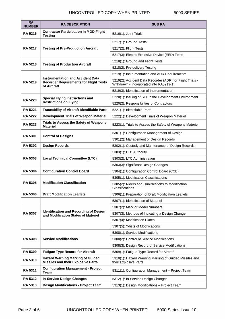
2. The 5000 Series (DME) RA are owned by Dir (Tech). Table E-1 below shows the current documents, along with the associated Regulation titles.
RA NUMBER
RA DESCRIPTION SUB RA
RA 5001 Certification and Release of Materiel 5001(1): Certification of Design
5001(2): Flight Trials
RA 5002
Remotely Piloted Air Systems (RPAS) Design and Modification Engineering (DME) Regulations
5002(1): Compliance with 5000 Series Regulatory Articles (RAs)
5002(2): Certification of Design
5002(3): Software Design Assurance
5002(4): Mass, Centre of Gravity (CofG) and Associated Data of Remotely Piloted Aircraft (RPA)
5002(5): Reporting of Mass for RPA Equipment
5002(6): Configuration Management – Project Team
5002(7): Design and Certification of RPA Engines
5002(8): Mass and CofG Data of RPA Engines and Jet Pipes
5002(9): Production Procedures for RPA Engines and Associated Equipment
5002(10): RPAS Integrity Management
5002(11): RPAS Ageing Aircraft Audit
RA 5101 DAOS Approval Procedures and Responsibilities
5101(1): Scheme Inclusion and Approval Award
5101(2): Design Organization Appointment
5101(3): Validity of Approval
RA 5102 Design and Development Responsibilities
5102(1): Responsibilities of a Contractor
5102(2): Contractor Responsibilities for Sub-Contractors
5102(3): Sub-Contractors
5102(4): Designs Using Government Furnished Assets
5102(5): Relationship Between Contractor and MOD
RA 5103 Certification of Design
5103(1): Approval of Certificate of Design
5103(2): Format of Certificate of Design
5103(3): Retention of Certificate of Design
5103(4): Certification of Sub-contracted Items
RA 5104 Material Specification Not used
RA 5105 Requalification and Production Testing 5105(1): Requirement for Requalification
5105(2): Requalification of Explosive Materiel
RA 5106 Aircraft Contractors’ Responsibilities
5106(1): Equipment Development
5106(2): Interface Requirements
5106(3): Systems and Equipment Installation
5106(4): Electro-magnetic Compatibility
RA 5107 Aircraft Repair Schemes 5107(1): Service Design Organization (SDO) Approval

5000 SERIES UNCONTROLLED COPY WHEN PRINTED
5000 Series Issue 10 UNCONTROLLED COPY WHEN PRINTED Page 2 of 6
RA NUMBER
RA DESCRIPTION SUB RA
5107(2): SDO Repair Schemes
5107(3): Design Organization (DO) Repair Schemes
RA 5201 Interchangeability 5201(1): Interchangeability of Materiel
RA 5202 Certification for Flight Trials 5202(1): Scope of Military Flight Test Permit (MFTP)
5202(2): MFTP Procedure
RA 5203 Requirement Specifications
5203(1): Environmental Effect
5203(2): Contract Specifications
5203(3): Sub-Contract Specifications
5203(4): Explosives, Electro-explosives Devices and Lasers
RA 5204 Information for Installation of Aircraft or Remotely Piloted Air ►Systems◄ Equipment
5204(1): Interface Responsibilities
RA 5205 Reporting of Mass for Aircraft Equipment 5205(1): Reporting of Mass for Aircraft Equipment
RA 5206 Sampling Procedure for In-Service Materiel 5206(1): Sampling Procedure
RA 5207 Identification under the NATO Codification System Not used
RA 5208 Testing of Experimental and Development Aircraft Equipment
5208(1): Equipment Standard
5208(2): Test Schedules
5208(3): Responsibility for Tests
5208(4): Test Reports
RA 5209 Relationship between Service Units, MOD and Contractors in the Development of Materiel
5209(1): MOD and Contractor Relationship
RA 5210 Packaging Not used
RA 5211 Mock-Ups and Working Rigs 5211(1): Mock-ups and Working Rigs Conference
5211(2): Direction on Mock-ups and Working Rigs
RA 5212 Mass, CG and Associated Data of Aircraft
5212(1): Submission of Data
5212(2): Mass and Centre of Gravity (CG) Determination
RA 5213 Final Examinations and Conferences 5213(1): Aircraft Standard
RA 5214 Schedule of Equipment – Appendix A to the Aircraft Specification 5214(1): Preparation and Submission of an Appendix A
RA 5215 Provision of Miscellaneous Data during Development
5215(1): Drawing of Systems for which a Working Rig is Required
5215(2): Models
5215(3): Information Required for Maintenance, Stowage and Transport of Aircraft Components
5215(4): External Colouring and Marking Drawings
5215(5): Armament Installation
5215(6): Armament Wiring Quality Assurance
5215(7): Torpedoes
5215(8): Weapon Harmonization
5215(9): Software (Program) Documentation
UNCONTROLLED COPY WHEN PRINTED 5000 SERIES
Page 3 of 6 UNCONTROLLED COPY WHEN PRINTED 5000 Series Issue 10
RA NUMBER
RA DESCRIPTION SUB RA
RA 5216 Contractor Participation in MOD Flight Testing 5216(1): Joint Trials
RA 5217 Testing of Pre-Production Aircraft
5217(1): Ground Tests
5217(2): Flight Tests
5217(3): Electro-Explosive Device (EED) Tests
RA 5218 Testing of Production Aircraft 5218(1): Ground and Flight Tests
5218(2): Pre-delivery Testing
RA 5219 Instrumentation and Accident Data Recorder Requirements for Flight Tests of Aircraft
5219(1): Instrumentation and ADR Requirements
5219(2): Accident Data Recorder (ADR) for Flight Trials - Withdrawn - Incorporated into RA5219(1)
5219(3): Identification of Instrumentation
RA 5220 Special Flying Instructions and Restrictions on Flying
5220(1): Issuing of SFI in the Development Environment
5220(2): Responsibilities of Contractors
RA 5221 Traceability of Aircraft Identifiable Parts 5221(1): Identifiable Parts
RA 5222 Development Trials of Weapon Materiel 5222(1): Development Trials of Weapon Materiel
RA 5223 Trials to Assess the Safety of Weapons Materiel 5223(1): Trials to Assess the Safety of Weapons Materiel
RA 5301 Control of Designs 5301(1): Configuration Management of Design
5301(2): Management of Design Records
RA 5302 Design Records 5302(1): Custody and Maintenance of Design Records
RA 5303 Local Technical Committee (LTC)
5303(1): LTC Authority
5303(2): LTC Administration
5303(3): Significant Design Changes
RA 5304 Configuration Control Board 5304(1): Configuration Control Board (CCB)
RA 5305 Modification Classification
5305(1): Modification Classifications
5305(2): Riders and Qualifications to Modification Classifications
RA 5306 Draft Modification Leaflets 5306(1): Preparation of Draft Modification Leaflets
RA 5307 Identification and Recording of Design and Modification States of Materiel
5307(1): Identification of Materiel
5307(2): Mark or Model Numbers
5307(3): Methods of Indicating a Design Change
5307(4): Modification Plates
5307(5): Y-lists of Modifications
RA 5308 Service Modifications
5308(1): Service Modifications
5308(2): Control of Service Modifications
5308(3): Design Record of Service Modifications
RA 5309 Fatigue Type Record for Aircraft 5309(1): Fatigue Type Record for Aircraft
RA 5310 Hazard Warning Marking of Guided Missiles and their Explosive Parts
5310(1): Hazard Warning Marking of Guided Missiles and their Explosive Parts
RA 5311 Configuration Management - Project Team 5311(1): Configuration Management – Project Team
RA 5312 In-Service Design Changes 5312(1): In-Service Design Changes
RA 5313 Design Modifications - Project Team 5313(1): Design Modifications – Project Team

5000 SERIES UNCONTROLLED COPY WHEN PRINTED
5000 Series Issue 10 UNCONTROLLED COPY WHEN PRINTED Page 4 of 6
RA NUMBER
RA DESCRIPTION SUB RA
RA 5320 Aircraft Maintenance Programme – Design Guidelines
5320(1): Aircraft Maintenance Programme – Design Guidelines
RA 5401 Provision of Service Technical Publications
5401(1): Provision of Service Technical Publications
5401(2): Validation of Service Technical Publications
5401(3): Verification of Service Technical Publications
5401(4): Amendments to Service Technical Publications
RA 5402 Validation and Verification of Service Technical Publications
5402(1): Withdrawn – Incorporated into RA 5401(2)
5402(2): Withdrawn – Incorporated into RA 5401(3)
RA 5403 Amendments to Service Technical Publications 5403(1): Withdrawn – Incorporated into RA 5401(4)
RA 5404 Fault Reporting and Investigation
5404(1): Fault Reporting
5404(2): Quarantine and Disposal
5404(3): Fault Investigation
RA 5405 Special Instructions (Technical) 5405(1): Special Instructions (Technical)
RA 5406 Aircrew Publications - Contractors Responsibilities
5406(1): Aircrew Publications – Contractors Responsibilities
RA 5501 Issue of MOD Owned Equipment
5501(1): Contractual Entitlement
5501(2): Demand Procedure
5501(3): Return of Equipment
RA 5502 Aircraft Maintenance Forms and Engineering Record Cards
5502(1): Applicability of Aircraft Maintenance Forms and Engineering Record Cards
5502(2): Delivery or Transfer of Aircraft
RA 5503 Loans of Aircraft for Demonstration by Contractors
5503(1): Applications for the Authorization of Loans of Aircraft
5503(2): Charges and Costs for and in Connection with the Loan
5503(3): Indemnity, Insurance, Notification of Accidents etc
5503(4): Acceptance of Terms and Conditions of the Loan
RA 5601 Design and Certification of Aircraft Engines 5601(1): Qualification Compliance Programme
RA 5602 Control of Critical Engine Parts 5602(1): Control of Critical Engine Parts
RA 5603 Design Change Approval and Validation of Modifications
5603(1): Design Change Approval and Validation of Modifications
RA 5604 Flight Clearance of Non-Production Standard and Prototype Units 5604(1): Prototype Flight Clearance
RA 5605 Engine Specification 5605(1): Engine Specification
RA 5606 Contractors Materiel and Process Specification Not used
RA 5607 Mass and Centre of Gravity Data of Aircraft Engines and Jet Pipes 5607(1): Engine/ECU and Jet Pipe Mass and CG
RA 5608 Engine and Jet Pipe Mock-Ups and Installation Jigs 5608(1):Engine and Jet Pipe Mock-Ups and Installation Jigs
RA 5609 Special Instructions (Technical) and Engineering Record Cards Not used
RA 5610 Technical Documentation for Engines and Accessories
5610(1): Technical Documentation for Engines and Accessories

UNCONTROLLED COPY WHEN PRINTED 5000 SERIES
Page 5 of 6 UNCONTROLLED COPY WHEN PRINTED 5000 Series Issue 10
RA NUMBER
RA DESCRIPTION SUB RA
RA 5611 Local Technical Committees for Engines and Associated Equipment Not used
RA 5612 Allotment and Movement of Engines 5612(1): Allotment and Movement of Engines
RA 5613 Reporting Procedures for Movement and Serviceability of Engines and Modules
5613(1): Movement and Serviceability of Engines and Modules
RA 5614 Repair/Salvage Schemes for Engines and Associated Equipment
5614(1): Repair/Salvage Schemes For Engines and Associated Equipment
RA 5615 Production Procedures for Engines and Associated Equipment
5615(1): Production Release Procedure
5615(2): Quality Verification Tests
RA 5616 Drawing Procedure, Control of Designs and Design Records
5616(1): Drawing Procedure, Control of Designs and Design Records
RA 5617 Post Delivery Fault Reporting and Investigation 5617(1): Post Delivery Fault Reporting and Investigation
RA 5720 Structural Integrity Management
5720(1): Structural Integrity Management
5720(2): Establishing Structural Integrity
5720(3): Sustaining Structural Integrity
5720(4): Validating Structural Integrity
5720(5): Recovering Structural Integrity
5720(6): Exploiting Structural Integrity
RA 5721 Systems Integrity Management
5721(1): Systems Integrity Management
5721(2): Establishing Systems Integrity
5721(3): Sustaining Systems Integrity
5721(4): Validating Systems Integrity
5721(5): Recovering Systems Integrity
5721(6): Exploiting Systems Integrity
RA 5722 Propulsion Integrity Management
5722(1): Propulsion Integrity Management
5722(2): Establishing Propulsion Integrity
5722(3): Sustaining Propulsion Integrity
5722(4): Validating Propulsion Integrity
5722(5): Recovering Propulsion Integrity
5722(6): Exploiting Propulsion Integrity
RA 5723 Ageing Aircraft Audit 5723(1): Ageing Aircraft Audit
RA5724 Life Extension Programme
5724(1): Requirement for a Life Extension Programme
5724(2): Development and Implementation of a Life Extension Programme
RA5725 Out of Service Date Extension Programme 5725(1): Out of Service Date Extension Programme
Table E-1: 5000 Series (DME) Regulatory Articles

5000 SERIES UNCONTROLLED COPY WHEN PRINTED
5000 Series Issue 10 UNCONTROLLED COPY WHEN PRINTED Page 6 of 6
Intentionally left blank for print pagination

UNCONTROLLED COPY WHEN PRINTED Regulatory Article 5001
RA 5001 Initial Issue UNCONTROLLED COPY WHEN PRINTED Page 1 of 2
RA 5001 - Certification and Release of Materiel
Rationale Release to Service (RTS) of airborne materiel by the MOD requires the Design Organization/Contractor to certify the design of materiel.
Contents 5001(1): Certification of Design
5001(2): Flight Trials
Regulation
5001(1)
Certification of Design 5001(1) The Contractor/Design Organization shall certify the extent
to which the design satisfies the requirements of the specification/Cardinal Point Specification (CPS) issued by or on behalf of the MOD.
Acceptable Means of Compliance
5001(1)
Certification of Design 1. Prior to the first flight of a new aircraft, aircraft weapon system, unmanned air vehicle, tethered balloon or airborne forces equipment, the extent to which the design complies with the requirements of the specification should be certified by the contractor by submission of a Certificate of Design, which should include any exceptions or limitations to the requirements specification.
2. Contractor's Inspection, Demonstration, Analysis and Test should establish the extent of compliance with the specification.
3. When compliance with the requirements of the specification has been demonstrably satisfied, a Certificate of Design for the relevant design standard should be submitted to the Project Team Leader (PTL).
4. The PTL should decide if modification action requires the re-issue or amendment of the Certificate of Design.
Guidance Material
5001(1)
Certification of Design 5. Where the required materiel is not available, a contract will be let for the design, including the necessary development and testing of the materiel.
6. The MOD may provide equipment, referred to as Government Furnished Assets (GFA), for embodiment in the materiel being designed and developed.
7. For aircraft, major weapon systems and associated equipment, joint conferences and meetings may be held to review the contractor's design proposals. For aircraft and aircraft installations, an examination of mock-ups, and a final conference may be convened.
8. Aircraft GSE release to service by MOD will be by acknowledgement of the issue of the Certificate of Design for the GSE by the PTL.
9. The certification and release procedure for previously designed commercially available materiel (commonly known as ‘COTS’ materiel) will be that already described, with a requirement specification, a Certificate of Design and where appropriate, a Certificate for Flight Trials and RTS. The contractor may submit previous evidence to demonstrate compliance with the requirements of the specification.

Regulatory Article 5001 UNCONTROLLED COPY WHEN PRINTED
Page 2 of 2 UNCONTROLLED COPY WHEN PRINTED RA 5001 Initial Issue
Regulation
5001(2)
Flight Trials 5001(2) The MOD shall determine whether any operating limitations,
in addition to those defined by the Contractor in the Military Flight Test Permit (MFTP), are to be included in the Aircraft Release by conducting official flight trials of aircraft.
Acceptable Means of Compliance
5001(2)
Flight Trials 10. Contractor's flight trials should be authorized by the issue of a MFTP.
11. The MFTP should be prepared by the Contractor and countersigned by the Type Airworthiness Authority (TAA).
12. A MFTP should be supported by a Safety Assessment Report.
13. A MFTP should relate to a particular design standard of an aircraft identified by registration number, and contains associated design and flight limitations.
14. If the design standard is changed the MFTP should be re-issued.
15. Where flight trials of a modified aircraft or modified airborne equipment are considered necessary, a Certificate of Design should be required to support the MFTP.
16. When modifications are being considered, the need for flight trials should be assessed.
17. The PTL should consider the results of Contractor and official trials in preparing or re-issuing or amending, the RTS.
Guidance Material
5001(2)
Flight Trials 18. Materiel may also be subjected to trials at MOD establishments. In the case of flight trials by the aircraft Contractor and MOD trials (the latter referred to as ‘official’ trials), they may be conducted on a joint basis.
19. The limitations defined in the Certificate may be altered only by formal amendment action.
20. Modification action may necessitate the re-issue or amendment of the Certificate of Design and, where appropriate, the MFTP and RTS.
21. Following any trials, the build standard and associated restrictions or limitations stated in the RTS may, if necessary, be amended.

UNCONTROLLED COPY WHEN PRINTED Regulatory Article 5002
RA 5002 Initial Issue UNCONTROLLED COPY WHEN PRINTED Page 1 of 8
RA 5002 - Remotely Piloted Air Systems (RPAS) Design and Modification Engineering (DME) Regulations
Rationale There is a requirement to define the responsibility and authority for design and modification of RPAS through either Service or contractor organizations.
Contents 5002(1): Compliance with 5000 Series Regulatory Articles (RAs)
5002(2): Certification of Design
5002(3): Software Design Assurance
5002(4): Mass, Centre of Gravity (CofG) and Associated Data of Remotely Piloted Aircraft (RPA)
5002(5): Reporting of Mass for RPA Equipment
5002(6): Configuration Management – Project Team
5002(7): Design and Certification of RPA Engines
5002(8): Mass and CofG Data of RPA Engines and Jet Pipes
5002(9): Production Procedures for RPA Engines and Associated Equipment
5002(10): RPAS Integrity Management 5002(11): RPAS Ageing Aircraft Audit
Regulation
5002(1)
Compliance with 5000 Series RAs 5002(1) The Type Airworthiness Authority (TAA) shall ensure that all
RPAS1 Design and Modifications are carried out in accordance with (iaw) the 5000 Series DME RAs.
Acceptable Means of Compliance 5002(1)
Compliance with 5000 Series RAs 1. Nil.
Guidance Material
5002(1)
Compliance with 5000 Series RAs 2. Where there is a difference between the regulation contained in this document and any other 5000 Series DME RAs this RA takes precedence for RPAS platforms.
3. The regulations listed in the contents section of this RA are adjusted to account for RPAS methods of design, construction, certification and most importantly, reduced Risk to Life (RtL). Hence this regulation must be followed for all classes of RPAS.
Regulation
5002(2)
Certification of Design
5002(2) For all RPAS, other than those identified below, the TAA shall comply with RA 51032.
For RPAS categorized as Class I(b) or I(c) that are Commercial Off-The-Shelf (COTS), the TAA shall ensure the intent of RA 51032 is achieved.
1 As per RA 1600 – RPAS, the phrase “all RPAS” will refer to “all RPAS less those categorized as Class I(a)” throughout this RA.

Regulatory Article 5002 UNCONTROLLED COPY WHEN PRINTED
Page 2 of 8 UNCONTROLLED COPY WHEN PRINTED RA 5002 Initial Issue
Acceptable Means of Compliance
5002(2)
Certification of Design 4. For RPAS categorized as Class I(b) or I(c) that are COTS, any recognized design standards used during development of the platform should be recorded. If the RPAS is not designed to any recognized airworthiness standards, the onus is on the TAA to demonstrate how product integrity is achieved. This argument should be contained within the Equipment Safety Assessment.
5. For RPAS categorized as Class I(b) or I(c) that are not COTS, Appendix A1 or A2 of RA 51032 should be completed, but is only required to include as a minimum:
a. The RPA type.
b. A list of all relevant standards that were used during the design (ie any software design standards, European Aviation Safety Agency Certification Specifications, Joint Aviation Requirements, etc).
c. A statement regarding the testing or analysis performed to ensure the Software and Structural Integrity of the platform; reference should also be made to the Equipment Safety Assessment.
Guidance Material
5002(2)
Certification of Design 6. It is possible that a RPAS will not be designed to any recognized certification standards. This may be acceptable depending on the categorization of the RPAS, however, the onus is on the TAA to ensure that the RPAS is still safe to operate within the limitations of the RTS.
7. Development of a robust Air System Safety Case (SC) is critical for platforms that are not required to undergo a formal certification process, ie for RPAS categorized as Class I(b) or (1c). RA 16003 - Annex B provides further guidance on the requirements for platforms not undergoing formal certification, with a list of suggested criteria.
Regulation
5002(3)
Software Design Assurance 5002(3) The TAA shall ensure that all RPAS comply with the
Software Design Assurance Level (DAL) requirements of Def Stan 00-970, Part 9, except for those RPAS categorized as Class I(b) or I(c) where the TAA shall demonstrate software assurance through completion of a hazard and risk analysis approach.
Acceptable Means of Compliance
5002(3)
Software Design Assurance 8. It is recognized that for RPAS categorized as Class I(b) or I(c), it may not be reasonably practicable to meet the Software DAL called out in Def Stan 00-970 Part 9. In such cases the software assurance strategy should be presented to the MAA to agree. The software assurance strategy should be used to develop the software argument in the Equipment Safety Assessment, giving particular attention to software items whose failure could lead to uncontrolled flight and/or a catastrophic loss.
Guidance Material
5002(3)
Software Design Assurance 9. Nil
2 RA 5103 – Certification of Design 3 RA 1600 – Remotely Piloted Air Systems (RPAS)

UNCONTROLLED COPY WHEN PRINTED Regulatory Article 5002
RA 5002 Initial Issue UNCONTROLLED COPY WHEN PRINTED Page 3 of 8
Regulation
5002(4)
Mass, CofG and Associated Data of RPA 5002(4) The TAA shall ensure that RA 52124 is complied with for all
RPAS, except those categorized as Class I(b) or I(c). The TAA shall ensure that a method is in place for
maintaining the weight and balance of each individual RPA for RPAS categorized as Class I(c).
Acceptable Means of Compliance
5002(4)
Mass, CofG and Associated Data of RPA 10. For RPAS categorized as Class I(c), the TAA should develop and maintain a procedure in the Air System Document Set (ADS) for checking the weight and balance of the RPA.
Guidance Material
5002(4)
Mass, CofG and Associated Data of RPA 11. For RPAS categorized as Class I(c), it is common practice that the design enables operators to routinely exchange components for repair purposes. For some platforms, the weight is controlled by limiting the extent of repairs carried out. As such, the weight and balance for platforms within the Class I(c) category is traditionally checked after assembly, and/or prior to every flight.
12. The onus is on the TAA to ensure that effective weight and balance control measures are in place for the platform to ensure the weight and balance remain within limits.
13. For RPAS categorized as Class I(b), a process is not required for maintaining the weight and balance of the platform.
Regulation
5002(5)
Reporting of Mass for RPA Equipment 5002(5) The TAA shall ensure that RA 52055 is complied with for all
RPAS, except those categorized as Class I(b) or I(c). The TAA shall ensure that the mass of RPA equipment is
recorded, listing all installed/removable equipment for RPAS categorized as Class I(c) prior to the RTS.
Acceptable Means of Compliance
5002(5)
Reporting of Mass for RPA Equipment 14. For RPAS categorized as Class I(c), the TAA should ensure that the mass of any installed equipment and systems is reported in the forms described in RA 52055 before the RTS of the RPAS. A single submission is acceptable.
Guidance Material
5002(5)
Reporting of Mass for RPA Equipment 15. For RPAS categorized as Class I(c), role fit equipment may not be applicable; however, there must still be a method for weight and balance to be easily checked by the operators prior to flight.
Regulation
5002(6)
Configuration Management – Project Team 5002(6) The TAA shall have a Configuration Management Plan in
place for all items of materiel that may be subject to modification for all RPAS, except those categorized as Class I(b).
For RPAS categorized as Class I(c) the TAA shall have a tailored Configuration Management Plan.
4 RA 5212 – Mass, C of G and Associated Data of Aircraft 5 RA 5205 – Reporting of Mass for Aircraft Equipment

Regulatory Article 5002 UNCONTROLLED COPY WHEN PRINTED
Page 4 of 8 UNCONTROLLED COPY WHEN PRINTED RA 5002 Initial Issue
Acceptable Means of Compliance
5002(6)
Configuration Management – Project Team 16. For all RPAS, except those categorized as Class I(b), or I(c) the AMC in RA 53016 should be followed.
17. For RPAS categorized as Class I(c), a documented process for controlling the configuration of all items that would affect the Equipment Safety Assessment should be provided.
Guidance Material
5002(6)
Configuration Management – Project Team 18. For RPAS categorized as Class I(b) or I(c) the configuration management system may be proportional to the RtL that the RPAS presents.
19. For these reasons, the requirements outlined in RA 53016 are not mandated; however, for any item that may affect the Equipment Safety Assessment a documented process will be utilized.
Regulation
5002(7)
Design and Certification of RPA Engines7 5002(7) For all RPAS, except those categorized as Class I(b), or I(c),
the TAA shall comply with RA 56018. For RPAS categorized as Class I(b) or I(c), the TAA shall
ensure an evaluation process is carried out for the engine, and is outlined in the Equipment Safety Assessment iaw RA 1220(2)9.
Acceptable Means of Compliance
5002(7)
Design and Certification of RPA Engines 20. For RPAS categorized as Class I(b) or I(c):
a. Where RA 56018 cannot be complied with, an evaluation process should be conducted on the engine to demonstrate that an appropriate level of safety can be achieved. The evaluation should form part of the Equipment Safety Assessment prepared iaw RA 1220(2)9.
b. For COTS engines, any recognized design standards and qualification evidence used during development of the platform should be recorded. If the engine is not designed to any recognized airworthiness standards the onus is on the TAA to reference how product integrity is achieved. This argument should be contained within the Equipment Safety Assessment.
Guidance Material
5002(7)
Design and Certification of RPA Engines 21. For RPAS categorized as Class I(b) or I(c), it is possible that an engine will not be designed to any recognized certification standards and have limited qualification compliance reports. The onus is on the TAA to ensure that the engine is still safe to operate within the limitations of the RTS.
22. Development of a robust Equipment Safety Assessment is critical for engines that are not required to undergo a formal certification process. An evaluation process will be conducted on the engine and, if applicable, its associated control, monitoring, fuel and cooling systems, to demonstrate that an appropriate level of safety can be achieved that will meet the Design Safety Target. RA 16003 provides further guidance on the requirements for platforms not undergoing formal certification, with a list of suggested criteria to be covered in Annex B.
6 RA 5301 – Control of Designs 7 The term “Engine” is used throughout this RA to describe all Propulsion devices that could be used in RPAS designs including; Gas Turbine Engines, Internal Combustion Engines, Electric Motors, Rockets, etc. 8 RA 5601 – Design and Certification of Aircraft Engines 9 RA 1220 – Project Team Airworthiness and Safety
UNCONTROLLED COPY WHEN PRINTED Regulatory Article 5002
RA 5002 Initial Issue UNCONTROLLED COPY WHEN PRINTED Page 5 of 8
Regulation
5002(8)
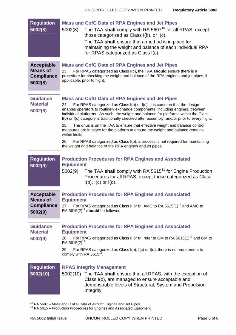
Mass and CofG Data of RPA Engines and Jet Pipes 5002(8) The TAA shall comply with RA 560710 for all RPAS, except
those categorized as Class I(b), or I(c). The TAA shall ensure that a method is in place for
maintaining the weight and balance of each individual RPA for RPAS categorized as Class I(c).
Acceptable Means of Compliance
5002(8)
Mass and CofG Data of RPA Engines and Jet Pipes 23. For RPAS categorized as Class I(c), the TAA should ensure there is a procedure for checking the weight and balance of the RPA engines and jet pipes, if applicable, prior to flight.
Guidance Material
5002(8)
Mass and CofG Data of RPA Engines and Jet Pipes 24. For RPAS categorized as Class I(b) or I(c), it is common that the design enables operators to routinely exchange components, including engines, between individual platforms. As such, the weight and balance for platforms within the Class I(b) or I(c) category is traditionally checked after assembly, and/or prior to every flight.
25. The onus is on the TAA to ensure that effective weight and balance control measures are in place for the platform to ensure the weight and balance remains within limits.
26. For RPAS categorized as Class I(b), a process is not required for maintaining the weight and balance of the RPA engines and jet pipes.
Regulation
5002(9)
Production Procedures for RPA Engines and Associated Equipment 5002(9) The TAA shall comply with RA 561511 for Engine Production
Procedures for all RPAS, except those categorized as Class I(b), I(c) or I(d).
Acceptable Means of Compliance
5002(9)
Production Procedures for RPA Engines and Associated Equipment 27. For RPAS categorized as Class II or III, AMC to RA 5615(1)11 and AMC to RA 5615(2)11 should be followed.
Guidance Material
5002(9)
Production Procedures for RPA Engines and Associated Equipment 28. For RPAS categorized as Class II or III, refer to GM to RA 5615(1)11 and GM to RA 5615(2)11
29. For RPAS categorized as Class I(b), I(c) or I(d), there is no requirement to comply with RA 561511.
Regulation
5002(10)
RPAS Integrity Management
5002(10) The TAA shall ensure that all RPAS, with the exception of Class I(b), are managed to ensure acceptable and demonstrable levels of Structural, System and Propulsion Integrity.
10 RA 5607 – Mass and C of G Data of Aircraft Engines and Jet Pipes 11 RA 5615 – Production Procedures for Engines and Associated Equipment

Regulatory Article 5002 UNCONTROLLED COPY WHEN PRINTED
Page 6 of 8 UNCONTROLLED COPY WHEN PRINTED RA 5002 Initial Issue
Acceptable Means of Compliance
5002(10)
RPAS Integrity Management 30. The plan for Integrity Management of the RPAS should be presented to the MAA by the TAA. Subject to the assessment carried out as part of the Equipment Safety Assessment for the RPAS, which recognizes the potential outcome of loss of Continuing Airworthiness, the TAA should apply the principles of the RA 5700: Integrity Management series, to ensure airworthiness is maintained through the life of the RPAS.
31. For RPAS categorized as Class I(d), II or III, the TAA should follow the Establish, Sustain, Validate, Recover, Exploit (ESVRE) approach for Integrity Management as outlined in RA 5720(1-6)12, RA 5721(1-6)13, and RA 5722(1-6)14.
32. For RPAS categorized as Class I(c), a tailored Integrity Management approach should be carried out by the TAA.
Guidance Material
5002(10)
RPAS Integrity Management 33. For RPAS categorized as Class II or III the requirements for Integrity Management are no different from those for manned aircraft.
34. For RPAS categorized as Class I(d), the requirements for Integrity Management are no different than manned aircraft with the exception of the requirement for Operational Loads Measurement / Operational Data Recording (OLM/ODR) programmes. These programmes are implemented on the platform at the discretion of the TAA. When determining whether to implement an OLM programme, the TAA ought to consider the impact that fatigue may pose on the airframe given its forecasted life span, and whether the usage is sufficiently limited by flight control and any self-protection systems so that flight outside the scope of the Design Usage Spectrum (DUS) articulated in the Statement of Operating Intent (SOI) is prevented.
35. For RPAS categorized as Class I(c) the TAA may chose to amalgamate Structural, System and Propulsion Integrity as an alternative to managing the ESVRE activities and Integrity Working Groups (IWG) of these specialties individually. The complexity of the Air System will determine whether it is more economical for the TAA to group them together or follow a traditional approach for Integrity Management. It is therefore acceptable for the TAA to run combined IWGs.
36. For RPAS categorized as Class I(c), the TAA may decide not to convene a Propulsion Integrity Working Group when the engine(s) are not considered a distinct system. In this case Propulsion Integrity will fall under System Integrity.
37. Annex A Table 1 lists the minimum requirements for Platform Integrity Management for RPAS categorized as Class I(c).
38. For RPAS categorized as Class I(b), specific Integrity Management activity is not required.
Regulation
5002(11)
RPAS Ageing Aircraft Audit
5002(11) The TAA shall ensure that consideration is given to the effects of degradation and the interaction of apparently unrelated ageing processes for all RPAS.
12 RA 5720 – Structural Integrity Management 13 RA 5721 – System Integrity Management 14 RA 5722 – Propulsion Integrity Management
UNCONTROLLED COPY WHEN PRINTED Regulatory Article 5002
RA 5002 Initial Issue UNCONTROLLED COPY WHEN PRINTED Page 7 of 8
Acceptable Means of Compliance
5002(11)
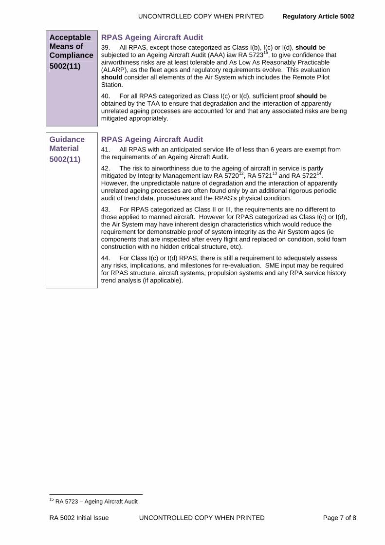
RPAS Ageing Aircraft Audit 39. All RPAS, except those categorized as Class I(b), I(c) or I(d), should be subjected to an Ageing Aircraft Audit (AAA) iaw RA 572315, to give confidence that airworthiness risks are at least tolerable and As Low As Reasonably Practicable (ALARP), as the fleet ages and regulatory requirements evolve. This evaluation should consider all elements of the Air System which includes the Remote Pilot Station.
40. For all RPAS categorized as Class I(c) or I(d), sufficient proof should be obtained by the TAA to ensure that degradation and the interaction of apparently unrelated ageing processes are accounted for and that any associated risks are being mitigated appropriately.
Guidance Material
5002(11)
RPAS Ageing Aircraft Audit 41. All RPAS with an anticipated service life of less than 6 years are exempt from the requirements of an Ageing Aircraft Audit.
42. The risk to airworthiness due to the ageing of aircraft in service is partly mitigated by Integrity Management iaw RA 572012, RA 572113 and RA 572214. However, the unpredictable nature of degradation and the interaction of apparently unrelated ageing processes are often found only by an additional rigorous periodic audit of trend data, procedures and the RPAS’s physical condition.
43. For RPAS categorized as Class II or III, the requirements are no different to those applied to manned aircraft. However for RPAS categorized as Class I(c) or I(d), the Air System may have inherent design characteristics which would reduce the requirement for demonstrable proof of system integrity as the Air System ages (ie components that are inspected after every flight and replaced on condition, solid foam construction with no hidden critical structure, etc).
44. For Class I(c) or I(d) RPAS, there is still a requirement to adequately assess any risks, implications, and milestones for re-evaluation. SME input may be required for RPAS structure, aircraft systems, propulsion systems and any RPA service history trend analysis (if applicable).
15 RA 5723 – Ageing Aircraft Audit

Regulatory Article 5002 UNCONTROLLED COPY WHEN PRINTED
Page 8 of 8 UNCONTROLLED COPY WHEN PRINTED RA 5002 Initial Issue
ANNEX A
Tailored Integrity Management Class I(c) RPAS
Table 1 – Tailored Integrity Management Class I(c) RPAS
Platform Integrity Class I(c)
In preference to separate IM as required by RAs 572012, 572113 and 572214 the TAA may assure IM via a tailored whole platform approach. A combined IM approach will ensure the intent of the individual RAs is met and it is expected that this is delivered via a suitable management framework such as ESVRE. The whole platform approach will also include as a minimum:
Establish – A tailored Platform Integrity Strategy Document (ISD) and SOI. All elements of the RPAS that contribute to safe operation including ground control stations will be included within the IM strategy.
Sustain – A framework that includes: an Integrity Management Plan and Integrity Management Working Groups that will provide Continuing Airworthiness for all elements of the air system. A system must be in place to determine and control RPA mass, CofG, and mass distribution.
Validate – Annual SOIU review extended to every 2 years, OLM/ODR programmes are not required where the RPAS usage can be shown to be sufficiently limited by flight control or similar self-protection systems such that flight outside the scope of the (DUS) articulated in the SOI is prevented.
Recover – Component failures will be recorded with enough fidelity to permit a fleet-wide assessment of structural health. If the fleet is experiencing repeated failures which have potential to result in platform loss, this must be documented and an appropriate management strategy implemented. Reviews of component lifing will be carried out, particularly where components that do not have individual lifing records may be moved between RPA and may exceed their original cleared life.
Exploit – Undertake structural Hazard and Accident analysis in the event of airworthiness risks arising from Structural Integrity concerns.

UNCONTROLLED COPY WHEN PRINTED Regulatory Article 5101
RA 5101 Issue 6 UNCONTROLLED COPY WHEN PRINTED Page 1 of 4
RA 5101 - Design Approved Organization Scheme (DAOS) Approval Procedures and Responsibilities
Rationale One of the Four Pillars of Airworthiness is the use of competent organizations. The DAOS is a mechanism by which competence of design organizations can be assured.
Contents 5101(1): Scheme Inclusion and Approval Award
5101(2): Design Organization Appointment
5101(3): ►Validity of Approval◄
Regulation
5101(1)
Scheme Inclusion and Approval Award 5101(1) An organization shall be included in the DAOS and awarded
approval for a defined range of products only when it is in the interests of MOD and when the organization has been accepted by the Military Aviation Authority (MAA).
Acceptable Means of Compliance 5101(1)
Scheme Inclusion and Approval Award 1. ►An organization seeking inclusion in the scheme should apply through the sponsoring Project Team Leader (PTL) to the MAA.◄
2. Before a review of the organization's design, development and post-delivery support arrangements is undertaken, the Project Team (PT) should satisfy the MAA that:
a. It is in the interests of MOD to include the organization in the Scheme.
b. The organization complies with the requirements of BS/EN/ISO 9001:2008 or equivalent as defined by Defence Quality Assurance Authority (DQAA).
3. To enable the MAA to assess an organization for inclusion in the scheme, the organization should submit the following information:
a. Classes of products or services and the technologies involved for which inclusion in the Scheme is sought.
b. Evidence of experience in preparation of specifications, and design, development, testing, engineering for manufacture and subsequent in-Service support of classes of products or services.
c. Details of design and build-standard control system, and in particular, of the methods of controlling and recording design changes to the established production build standard.
d. Details of testing facilities appropriate to the class of work and its application, including environmental, ground and flight testing where necessary.
e. Evidence of familiarity with MOD procedures applicable to the appropriate class of work.
f. Evidence of an independent airworthiness scrutiny of the design, with senior staff responsible reporting to an appropriate board member (or authorized equivalent where there is no board).
g. Names, qualifications, experience, and other relevant details of board members and senior design staff proposed as signatories for Certificates of Design.

Regulatory Article 5101 UNCONTROLLED COPY WHEN PRINTED
Page 2 of 4 UNCONTROLLED COPY WHEN PRINTED RA 5101 Issue 6
Acceptable Means of Compliance
5101(1)
h. Names, qualifications, experience and other relevant details of senior staff proposed as signatories for Military Flight Test Permit (MFTP) and Flight Trials reports.
i. Particulars of senior staff members responsible for design and development, with details of their responsibilities together with a chart of the organization's structure showing the names and positions of senior staff members who will be responsible for design and development.
j. Statement of the numbers of other technical and design staff.
k. Name and other details of the proposed safety officer.
l. Evidence of status in the United Kingdom Register of Quality Assessed Companies.
4. ►◄
5. The DAOS approval should list the broad classes of flight testing which have been authorized and the contractor’s senior personnel associated with that authorization. Any changes in such personnel, or in the associated organization and facilities relevant to the scope of the authorization should be reported in writing to the MAA.
6. If an organization wishes to change the class of products or services listed in the scope shown on its Design Approved Organizations Certificates, it should submit to the MAA the relevant information in accordance with the requirements of the 5100 series of Regulatory Articles.
7. ►◄
8. ►To demonstrate direct compliance with the DAOS requirements, a design organization with European Aviation Safety Agency (EASA )Part 21 Subpart J approval should submit their Exposition, providing it covers the required scope of approval, as supplementary evidence in support of their application seeking inclusion in the scheme. The MAA will make an assessment of what additional level of assurance is required to manage the differences between the EASA Subpart J approval and the DAOS requirements.◄
Guidance Material
5101(1)
Scheme Inclusion and Approval Award 9. When it is considered that there is a case for the organization to be included in the Scheme a detailed appraisal must be carried out, usually at the organization's premises. The appraisal will be carried out by a team of MAA/MOD specialists or its agents. The appraisal team will seek to establish long term confidence in the organization's design, development and test personnel, company structure and facilities relevant to the classes of work concerned.
10. ►◄
11. The MAA will examine the organization in terms of:
a. The current and projected technical activities.
b. The design and related supporting company structure and facilities.
c. The qualifications and experience of the relevant staff.
12. When evidence presented by the organization demonstrates that it satisfies the MAA requirements, a design approved organizations certificate will be issued listing:
a. The scope of the approval (a generalised description or list of the classes of products and services).
b. The names of the approved signatories for the certificates of design:
(1) The board members (or their authorized equivalents in cases where there is no board) who in the organization have the overall responsibility for the availability of resources for, and the security of, the design.

UNCONTROLLED COPY WHEN PRINTED Regulatory Article 5101
RA 5101 Issue 6 UNCONTROLLED COPY WHEN PRINTED Page 3 of 4
Guidance Material
5101(1)
(2) The designer who has participated in the design function and who is responsible for the technical adequacy and integrity of the design.
(3) Alternative signatories will be listed separately under terms notified to the organization by the MAA.
c. The names of the approved signatories of MFTP and for Flight Trials Reports.
13. DAOS Members will be subject to periodic compliance reassurance activities conducted by or on behalf of the MAA. Costs for periodic compliance reassurance activities conducted by or on behalf of MAA will not be recoverable from MOD.
14. ►◄
15. List of Organizations who have been granted approval will be published by the MAA.
16. Inclusion in DAOS is an essential pre-requisite for the award of design and development contracts for aircraft, systems and associated equipment, and airborne explosive ordnance and armament equipment. It is recognition that the MOD accepts certification by the organization and that a specified performance attribute or objective has been achieved.
17. This regulation applies to both service and civil organizations conducting design activities.
Regulation
5101(2)
Design Organization Appointment 5101(2) The ►appointment of◄a Design Organization or Co-
ordinating Design Organization ►shall be in accordance with RA1005.◄
Acceptable Means of Compliance
5101(2)
Design Organization Appointment 18. ►Nil.◄
Guidance Material
5101(2)
Design Organization Appointment 19. Nil.
Regulation
5101(3)
►Validity of Approval
5101(3) An approval shall be issued for an unlimited duration. It shall remain valid subject to:
a. The organization remaining in compliance with applicable RAs; and
b. The MAA or its nominated representative being granted access to the organization to determine continued compliance with applicable RAs; and
c. The approval certificate not being surrendered, suspended or revoked.◄
Regulatory Article 5101 UNCONTROLLED COPY WHEN PRINTED
Page 4 of 4 UNCONTROLLED COPY WHEN PRINTED RA 5101 Issue 6
Acceptable Means of Compliance
5101(3)
►Validity of Approval
20. Organizations should confirm in writing at least every 3 years and prior to any formal MAA surveillance that the contents of their approval certificate and exposition remain valid. Failure to provide the required confirmation may result in the suspension of the approval.
21. The organization should notify the MAA and the PTL and seek approval of any change, which affects its continued possession of approval including any proposed change of a design signatory on the Design Approval Certificate. ◄
Guidance Material
5101(3)
►Validity of Approval
22. Nil.◄

UNCONTROLLED COPY WHEN PRINTED Regulatory Article 5102
RA 5102 Initial Issue UNCONTROLLED COPY WHEN PRINTED Page 1 of 4
RA 5102 - Design and Development Responsibilities
Rationale When a contractor is appointed as a Co-ordinating / Design Organization it is essential that his responsibilities for design and development of contracted aircraft, weapons, electronics and associated materiel are such that the design of the resultant materiel is clearly certified against the contract specification.
Contents 5102(1): Responsibilities of a Contractor
5102(2): Contractor Responsibilities for Sub-Contractors
5102(3): Sub-Contractors
5102(4): Designs using Government Furnished Assets
5102(5): Relationship between Contractor and MOD
Regulation 5102(1)
Responsibilities of a Contractor 5102(1) A contractor when appointed as a Co-ordinating Design
Organization for a system or equipment, shall fulfil the stated requirements of a Design Organization or Co-ordinating Design Organization.
Acceptable Means of Compliance 5102(1)
1. When a contractor is appointed Design Organization or Co-ordinating Design Organization, his responsibilities to the MOD should include:
a. Design of the materiel, including all necessary development and testing, to the requirements of the contract specification.
b. Preparation, updating and custody of specifications, drawings and other data associated with the design of the materiel.
c. Preparation, collection, analysis and maintenance of data comprising evidence of design and system safety in accordance with a Safety Management Plan agreed with the PTL.
d. Submission of reports, as required, on progress of the work.
e. Preparing an appropriate certificate of design and its submission for MOD acceptance (See RA 5103).
f. Ensuring that the design will be suitable for production in facilities agreed between the contractor and MOD.
g. Design of packaging as required for the materiel.
h. Preparation of, or supply of information for, the necessary technical publications.
i. Collaboration with the relevant PT and it’s agencies in the preparation and provision of information for maintenance of the materiel.
j. Post design services.
Guidance Material 5102(1)
2. This RA applies to contractors who hold General or Particular Design Approval for the work being done. When a contractor is not design approved, the procedure to be followed will be stated in the contract.

Regulatory Article 5102 UNCONTROLLED COPY WHEN PRINTED
Page 2 of 4 UNCONTROLLED COPY WHEN PRINTED RA 5102 Initial Issue
Regulation 5102(2)
Contractor Responsibilities for Sub-Contractors 5102(2) The contractor shall be responsible to the MOD for his sub-
contractor's work.
Acceptable Means of Compliance 5102(2)
3. Nomination of a sub-contractor as a Design Organization should not relieve the contractor of his responsibilities. The contractor should make such arrangements with his sub-contractors, and they with theirs as will ensure that the sub-contracted materiel is satisfactory and that the relevant procedures of the 5000 series of RAs are followed. In particular, the contractor should:
a. Provide and maintain adequate specifications for sub-contracted materiel, delegate authority as appropriate for the detailed design of the materiel and agree the arrangements for preparation, updating and custody of drawings and other design records, and for design acceptance.
b. Satisfy himself that the design and testing of sub-contracted materiel are adequate for the proposed application.
c. Obtain from sub-contractors nominated as Design Organizations in accordance with RA 5101, a Certificate of Design that the materiel complies with the specification, and confirm in writing to the sub-contractor his acceptance of the certification.
Guidance Material 5102(2)
4. Any MOD technical representation at a sub-contractor's works in relation to the requirements of this section will be agreed between MOD and the contractor.
Regulation 5102(3)
Sub-Contractors 5102(3) Before a contractor places a sub-contract for any significant
design or development work he shall notify the PTL of the name of the sub-contractor, the nature of the work and the technical requirements.
Acceptable Means of Compliance 5102(3)
5. When a sub-contractor is not design approved the contractor should either incorporate the design of the sub-contracted items (other than standard parts) in his own drawings or should ensure that his sub-contractor follows the relevant procedures of the 5000 series regulations.
Guidance Material 5102(3)
6. Nil

UNCONTROLLED COPY WHEN PRINTED Regulatory Article 5102
RA 5102 Initial Issue UNCONTROLLED COPY WHEN PRINTED Page 3 of 4
Regulation 5102(4)
Designs using Government Furnished Assets 5102(4) The Contractor shall only alter the design of Government
Furnished Assets (GFA) with the authority of the MOD.
Acceptable Means of Compliance 5102(4)
7. If the contractor has any doubt about the design suitability of any item, or has proposals for design changes, he should advise the MOD at the earliest opportunity, preferably at the time of agreement of the specification for the main item of materiel.
8. The contractor should ensure that the design of the installation using GFA is in accordance with the specific requirements of such equipments.
Guidance Material 5102(4)
9. Nil.
Regulation 5102(5)
Relationship between Contractor and MOD 5102(5) As necessary, during the design, development, construction
and testing of materiel the contractor shall make available to MOD drawings, design data, calculations and reports of important tests, such as wind tunnel, structural, safety, functioning or flight tests, so that questions which may affect the safety or performance of the completed project may be discussed at an early stage.
Acceptable Means of Compliance 5102(5)
10. Adequate arrangements should be made for significant tests to be witnessed by appropriate MOD representatives.
Guidance Material 5102(5)
11. The relevant contract will specify the MOD officer (normally the PTL) to whose satisfaction the work is to be performed. The MOD reserves the right to oversee design and development activities to the extent necessary for the discharge of its responsibilities in the procurement of materiel.

Regulatory Article 5102 UNCONTROLLED COPY WHEN PRINTED
Page 4 of 4 UNCONTROLLED COPY WHEN PRINTED RA 5102 Initial Issue

UNCONTROLLED COPY WHEN PRINTED Regulatory Article 5103
RA 5103 Issue 2 UNCONTROLLED COPY WHEN PRINTED Page 1 of 14
►This RA has been substantially re-written; for clarity no change marks are presented – please read RA in entirety◄
RA 5103 – Certification of Design
Rationale Certification of Design (CofD) is required to identify the extent to which the requirements of the specification have been achieved.
Contents 5103(1): Approval of Certificate of Design
5103(2): Format of Certificate of Design
5103(3): Retention of Certificate of Design
5103(4): Certification of Sub-contracted Items
Regulation 5103(1)
Approval of Certificate of Design 5103(1) The CofD shall be signed by approved members of the
Design Organization (DO) and the Project Team Leader (PTL).
Acceptable Means of Compliance 5103(1)
Approval of Certificate of Design
1. The DO should submit the CofD and its supporting documentation to the PTL.
2. The PTL should signify the acceptance of the CofD, including any exceptions and limitations, by signing the box on the CofD reserved for this purpose.
Guidance Material 5103(1)
Approval of Certificate of Design
3. The methods of checking design calculations, including the procedure for verifying computer outputs, may be subject to the agreement of the PTL, e.g. in the case of novel or contentious areas or where substantiation by the MOD is required.
4. Where significant changes are made to a certified design a new certificate may be required by the PTL.
5. The DO is to note that under some circumstances, due to the declared limitations and exceptions against which the materiel meets the specifications, the PTL may conditionally accept a standard of design. In such cases the PTL will indicate the qualified acceptance by endorsing the CofD with the relevant conditions.
6. Acceptance by PTL of the CofD does not imply acceptance of responsibility for the design, which remains with the DO.
7. DO signatories must be approved in accordance with RA1005 and as identified in RA5101.
Regulation 5103(2)
Format of Certificate of Design 5103(2) Certificates of Design (CofDs) shall be provided on the
appropriate form.

Regulatory Article 5103 UNCONTROLLED COPY WHEN PRINTED
Acceptable Means of Compliance 5103(2)
Format of Certificate of Design
8. Appropriate forms for CofDs can be found in Annexes A – C and should be supported by:
a. A Configuration Status Record (CSR) or equivalent drawing list appropriate to the materiel.
b. A list of reports on all tests conducted to show compliance with the specification.
c. A list of subsidiary CofDs agreed by the Design Organization (DO) for materiel designed and developed by other DOs and incorporated in the Design. The CofDs for Government Furnished Assets (GFA) integrated into the design should be provided to the DO by the PT.
d. Specific evidence of structural integrity as defined in Annexes A – C.
e. A Safety Assessment in accordance with Def Stan 00-56 that demonstrates that the certified design is tolerably safe for the intended purpose.
Guidance Material 5103(2)
Format of Certificate of Design
9. The CofD forms are to be reproduced locally. The DO is to consult the PT if there is any doubt which form is appropriate, selecting from:
a. Appendix A1 – CofD for Aircraft.
b. Appendix A2 – CofD for use by Organizations approved for the Design of Modifications in Aircraft.
c. Appendix B1 – CofD for a Component/Equipment/System.
d. Appendix C1 – CofD for Guided Weapons.
10. The security classification applicable to each CofD must be marked in accordance with the Contractor’s Security Handbook.
Regulation 5103(3)
Retention of Certificate of Design 5103(3) The DO shall retain the original signed CofD with the master
records.
Acceptable Means of Compliance 5103(3)
Retention of Certificate of Design
11. The DO should distribute copies of the accepted CofD and the master records in accordance with the instructions of the PTL.
Guidance Material 5103(3)
Retention of Certificate of Design
12. Nil.
Regulation 5103(4)
Certification of Sub-contracted Items
5103(4) The DO shall submit a CofD to the PTL for sub-contracted items when they are accepted by the DO.
Page 2 of 14 UNCONTROLLED COPY WHEN PRINTED RA 5103 Issue 2

UNCONTROLLED COPY WHEN PRINTED Regulatory Article 5103
RA 5103 Issue 2 UNCONTROLLED COPY WHEN PRINTED Page 3 of 14
Acceptable Means of Compliance 5103(4)
Certification of Sub-contracted Items
13. If the CofD for sub-contracted items contain exceptions or limitations affecting overall system performance, the DO should list the exceptions or limitations and state their likely consequences.
Guidance 5103(4)
Certification of Sub-contracted Items
14. Nil.
Regulatory Article 5103 UNCONTROLLED COPY WHEN PRINTED
ANNEX A PARTICULAR REQUIREMENTS FOR AIRCRAFT
NOTE For aircraft installed and associated equipment where separate certification is a requirement, see Appendix B1.
A.1 Certificates of Design
A.1.1 The CofD must be chosen from Appendix A1 or from Appendix A2.
A.1.2 Following MAA agreement a DO may use other methods of design certification in the following circumstances:
A.1.2.1 When a contract for the work calls for special methods of certification.
A.1.2.2 For a Service derivative of a civil type when it is appropriate to work to:
a) British Civil Airworthiness Requirements (BCAR).
b) Joint Airworthiness Requirements (JAR).
c) Federal Airworthiness Requirements (FAR).
d) European Aviation Safety Agency (EASA), Implementing Rules (IR) and Certification Specifications (CS).
NOTE: When materiel designed by the designer’s sub-contractor is incorporated into a design, the DO is recommended to seek certification in the style of the Declaration of Design and Performance (DDP) in BS G 262:1998.
A.2 Structural Integrity
A.2.1 The requirements of RA5103(2) 8.d must be satisfied by the provision of a Type Record comprising:
a) A general arrangement and description of the aircraft.
b) A summary of the design assumptions and/or criteria for the aircraft and all major components.
c) The critical loading, shear-force, bending moment and torque distributions with mass distributions.
d) Calculation of reserve factors at critical sections and at a number of points in the main structural elements, particularly at joints or discontinuities. The associated structural and material data must be tabulated for the relevant critical and near critical design cases, with a reference to the final stress files. (See the following Note).
NOTE All cases of reserve factors less than 1.2 for Structurally Significant Items (SSI) must be included, all cases of reserve factors less than 1.0 for minor structural items must be included.
e) A list of final check stress reports/files.
f) A summary of the results of all tests made to confirm the design assumptions/criteria (A.2.1 b. above).
g) A summary of tests confirming the functional integrity of software used in structural calculations
A.2.2 A fatigue Type Record for Aircraft may also be a requirement (RA5300 series).
Page 4 of 14 UNCONTROLLED COPY WHEN PRINTED RA 5103 Issue 2

UNCONTROLLED COPY WHEN PRINTED Regulatory Article 5103
RA 5103 Issue 2 UNCONTROLLED COPY WHEN PRINTED Page 5 of 14
APPENDIX A1 MINISTRY OF DEFENCE CERTIFICATE OF DESIGN FOR AIRCRAFT
Reference No
Issue No
Aircraft Type Contract No
CSR Reference Issue
Test report List Reference Issue
Subsidiary CofDs List Reference Issue
Type Record Reference Issue
Software Standard Reference Issue
We, the designers of the above, hereby certify that:
1. With the exceptions and limitations stated in List No 1 attached, the above complies with the design airworthiness requirements of:
Specification Issue
Up to and including Amendment
Issued by
2. The calculations made during the course of design have been checked and every reasonable precaution taken to ensure their accuracy.
3. The design data, calculations, reports on tests and list of drawings supplied by us to MOD are a true and accurate record of the design.
4. All supporting CofDs have been received.
5. With the exceptions stated in List No 2 attached, compliance with the flying performance, including handling qualities, defined by the above Specification, has been demonstrated by flight tests covered by the reports in list No 3 attached.
6. A Safety Assessment has been prepared.
MAA Form 100

Regulatory Article 5103 UNCONTROLLED COPY WHEN PRINTED
Attachments:
List No 1 Exceptions and Limitations.
List No 2 Flying performance characteristics, including handling qualities, which have not been demonstrated by flight tests.
List No 3 Flight Test Reports.
DESIGN SIGNATORIES
Approved Design signatory
Name Signature:
Date
Approved Board signatory
Name Signature
Date
For (Design Organization)
DAOS Approval Reference No.
Note: The same signatory may not sign for both Board and Design on the same form.
FOR MOD USE ONLY
Exceptions and limitations referred to in List 1 are accepted on behalf of the MOD, such acceptance extends only to the matters stated and are not to be treated as extending by implication to any other requirement of the specifications; nor does it imply acceptance by the MOD of responsibility for all or any part of the design.
Name Signature:
Date
MAA Form 100
Page 6 of 14 UNCONTROLLED COPY WHEN PRINTED RA 5103 Issue 2
UNCONTROLLED COPY WHEN PRINTED Regulatory Article 5103
RA 5103 Issue 2 UNCONTROLLED COPY WHEN PRINTED Page 7 of 14
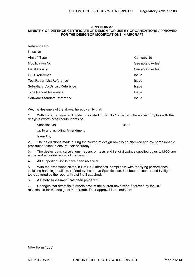
APPENDIX A2 MINISTRY OF DEFENCE CERTIFICATE OF DESIGN FOR USE BY ORGANIZATIONS APPROVED
FOR THE DESIGN OF MODIFICATIONS IN AIRCRAFT
Reference No
Issue No
Aircraft Type Contract No
Modification No See note overleaf
Installation of See note overleaf
CSR Reference Issue
Test Report List Reference Issue
Subsidiary CofDs List Reference Issue
Type Record Reference Issue
Software Standard Reference Issue
We, the designers of the above, hereby certify that:
1. With the exceptions and limitations stated in List No 1 attached, the above complies with the design airworthiness requirements of:
Specification Issue
Up to and including Amendment
Issued by
2. The calculations made during the course of design have been checked and every reasonable precaution taken to ensure their accuracy.
3. The design data, calculations, reports on tests and list of drawings supplied by us to MOD are a true and accurate record of the design.
4. All supporting CofDs have been received.
5. With the exceptions stated in List No 2 attached, compliance with the flying performance, including handling qualities, defined by the above Specification, has been demonstrated by flight tests covered by the reports in List No 3 attached.
6. A Safety Assessment,has been prepared.
7. Changes that affect the airworthiness of the aircraft have been approved by the DO responsible for the design of the aircraft. Their approval is recorded in:
MAA Form 100C

Regulatory Article 5103 UNCONTROLLED COPY WHEN PRINTED
Attachments:
List No 1 Exceptions and Limitations.
List No 2 Flying performance characteristics, including handling qualities, which have not been demonstrated by flight tests.
List No 3 Flight Test Reports.
NOTE Insert here the official modification number. If there is no modification number insert nomenclature of equipment installed.
DESIGN SIGNATORIES
Approved Design signatory
Name Signature:
Date
Approved Board signatory
Name Signature
Date
For (Design Organization)
DAOS Approval Reference No.
Note: The same signatory may not sign for both Board and Design on the same form.
FOR MOD USE ONLY
Exceptions and limitations referred to in List 1 are accepted on behalf of the MOD, such acceptance extends only to the matters stated and are not to be treated as extending by implication to any other requirement of the specifications; nor does it imply acceptance by the MOD of responsibility for all or any part of the design.
Name Signature:
Date
MAA Form 100C
Page 8 of 14 UNCONTROLLED COPY WHEN PRINTED RA 5103 Issue 2

UNCONTROLLED COPY WHEN PRINTED Regulatory Article 5103
RA 5103 Issue 2 UNCONTROLLED COPY WHEN PRINTED Page 9 of 14
ANNEX B PARTICULAR REQUIREMENTS FOR COMPONENTS, EQUIPMENT OR SYSTEMS
B.1 Certificates of Design
B.1.1 Certificates of Design must normally be the MAA Form 100A (see Appendix B1).
B.1.2 Following MAA agreement a DO may use other methods of design certification in the following circumstances:
B.1.2.1 When the contract for the work calls for special methods of certification.
B.1.2.2 For a Service derivative of a civil type when permission has been granted by MAA to work to:
a) British Civil Airworthiness Requirements (BCAR).
b) Joint Airworthiness Requirements (JAR).
c) Federal Airworthiness Requirements (FAR).
d) European Aviation Safety Agency (EASA) Implementing Rules (IR) and Certification Specifications (CS).
NOTE When materiel designed by designers sub-contractors is incorporated into a design, the DO is recommended to seek certification in style of the DDP in BS G 262:1998.
B.2 Structural Integrity of Aircraft Components, Equipment or Systems
The requirements of RA5103(2) 8.d must be satisfied by the provision of similar data, suitable to the case, as for aircraft (see Appendix A, clause A.2.1).
B.3 Structural Clearance of Airborne Electronic Equipment
Normally the DO will have an authorized structural design signatory with suitable experience able to sign as the designer on the CofD. However, when the DO does not have an authorized structural design signatory, then the structural design of airborne electronic equipment section must be counter signed by an approved Structural Clearance signatory of an alternative DAOS organization.

Regulatory Article 5103 UNCONTROLLED COPY WHEN PRINTED
APPENDIX B1 MINISTRY OF DEFENCE CERTIFICATE OF DESIGN FOR A COMPONENT/EQUIPMENT/SYSTEM
Reference No
Issue No
Component/Equipment/System* Contract No
CSR Reference Issue
Test Report List Reference Issue
Subsidiary CofDs List Reference Issue
Type Record Reference Issue
Software Standard Reference Issue
We, the designers of the above, hereby certify that:
1. With the exceptions and limitations stated in List No 1 attached and the performance statement stated in List 2, the above complies with the requirements of:
Specification Issue
Up to and including Amendment
Issued by
2. The calculations made during the course of design have been checked and every reasonable precaution taken to ensure their accuracy.
3. The design data, calculations, reports on tests and list of drawings supplied by us to MOD are a true and accurate record of the design.
4. All supporting CofDs have been received.
5. A Safety Assessment has been prepared
*Delete as appropriate
MAA Form 100A
Page 10 of 14 UNCONTROLLED COPY WHEN PRINTED RA 5103 Issue 2
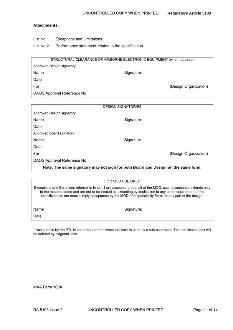
UNCONTROLLED COPY WHEN PRINTED Regulatory Article 5103
RA 5103 Issue 2 UNCONTROLLED COPY WHEN PRINTED Page 11 of 14
Attachments:
List No 1 Exceptions and Limitations.
List No 2 Performance statement related to the specification.
STRUCTURAL CLEARANCE OF AIRBORNE ELECTRONIC EQUIPMENT (when required)
Approved Design signatory
Name Signature:
Date
For (Design Organization)
DAOS Approval Reference No.
DESIGN SIGNATORIES
Approved Design signatory
Name Signature:
Date
Approved Board signatory
Name Signature
Date
For (Design Organization)
DAOS Approval Reference No.
Note: The same signatory may not sign for both Board and Design on the same form.
FOR MOD USE ONLY
Exceptions and limitations referred to in List 1 are accepted on behalf of the MOD, such acceptance extends only to the matters stated and are not to be treated as extending by implication to any other requirement of the specifications; nor does it imply acceptance by the MOD of responsibility for all or any part of the design.
Name Signature:
Date
* Acceptance by the PTL is not a requirement when this form is used by a sub-contractor. The certification box will be deleted by diagonal lines.
MAA Form 100A
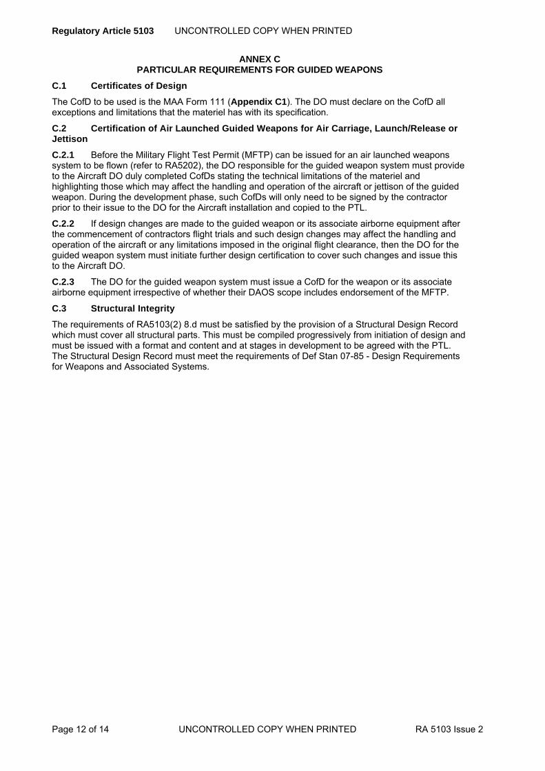
Regulatory Article 5103 UNCONTROLLED COPY WHEN PRINTED
ANNEX C PARTICULAR REQUIREMENTS FOR GUIDED WEAPONS
C.1 Certificates of Design
The CofD to be used is the MAA Form 111 (Appendix C1). The DO must declare on the CofD all exceptions and limitations that the materiel has with its specification.
C.2 Certification of Air Launched Guided Weapons for Air Carriage, Launch/Release or Jettison
C.2.1 Before the Military Flight Test Permit (MFTP) can be issued for an air launched weapons system to be flown (refer to RA5202), the DO responsible for the guided weapon system must provide to the Aircraft DO duly completed CofDs stating the technical limitations of the materiel and highlighting those which may affect the handling and operation of the aircraft or jettison of the guided weapon. During the development phase, such CofDs will only need to be signed by the contractor prior to their issue to the DO for the Aircraft installation and copied to the PTL.
C.2.2 If design changes are made to the guided weapon or its associate airborne equipment after the commencement of contractors flight trials and such design changes may affect the handling and operation of the aircraft or any limitations imposed in the original flight clearance, then the DO for the guided weapon system must initiate further design certification to cover such changes and issue this to the Aircraft DO.
C.2.3 The DO for the guided weapon system must issue a CofD for the weapon or its associate airborne equipment irrespective of whether their DAOS scope includes endorsement of the MFTP.
C.3 Structural Integrity
The requirements of RA5103(2) 8.d must be satisfied by the provision of a Structural Design Record which must cover all structural parts. This must be compiled progressively from initiation of design and must be issued with a format and content and at stages in development to be agreed with the PTL. The Structural Design Record must meet the requirements of Def Stan 07-85 - Design Requirements for Weapons and Associated Systems.
Page 12 of 14 UNCONTROLLED COPY WHEN PRINTED RA 5103 Issue 2

UNCONTROLLED COPY WHEN PRINTED Regulatory Article 5103
RA 5103 Issue 2 UNCONTROLLED COPY WHEN PRINTED Page 13 of 14
APPENDIX C1 MINISTRY OF DEFENCE CERTIFICATE OF DESIGN FOR GUIDED WEAPONS
Reference No
Issue No
Weapon System Contract No
Equipment Nomenclature
CSR Reference Issue
Test report List Reference Issue
Subsidiary CofDs List Reference Issue
Performance Statement Issue
Structural Design Record Issue
Software Standard Reference Issue
Which is (indicate as appropriate):
A complete weapon system An airborne or ground support equipment
A complete missile Part of a missile or support equipment
The above, subject to the limitations stated in 8 below, is for (indicate all applicable):
Evaluation Trials Firing at Sea
Practice Firings Land Carriage
Ground Firing Trials Firing on Land Vehicles
Service Firings Carriage on Aircraft
Carriage at Sea Firing on Aircraft
MAA Form 111

Regulatory Article 5103 UNCONTROLLED COPY WHEN PRINTED
Page 14 of 14 UNCONTROLLED COPY WHEN PRINTED RA 5103 Issue 2
We, the designers of the above equipment, hereby certify that:
1. With the exceptions stated in 8 below, the design of the above hardware and software complies with:
a. The requirements stated in: Issued by:
b. Def Stan 07-85 .
2. The calculations made during the course of design have been checked and every reasonable precaution taken to ensure their accuracy.
3. The CSR relating to this equipment, all calculations and associated design data, and all test reports submitted by us are a true record of this equipment.
4. Every reasonable precaution has been taken to ensure the safety of all hazardous items directly or indirectly associated with the equipment.
5. All relevant supporting CofDs have been received.
6. A Safety Assessment has been prepared.
7. Installations and other relevant instructions are given in:
8. Exceptions
9. Limitations:
DESIGN SIGNATORIES
Approved Design signatory
Name Signature:
Date
Approved Board signatory
Name Signature
Date
For (Design Organization)
DAOS Approval Reference No.
Note: The same signatory may not sign for both Board and Design on the same form.
FOR MOD USE ONLY
Exceptions and limitations referred to in paragraphs 8 & 9 are accepted on behalf of the MOD, such acceptance extends only to the matters stated and are not to be treated as extending by implication to any other requirement of the specifications; nor does it imply acceptance by the MOD of responsibility for all or any part of the design.
Name Signature:
Date
*Acceptance by the PTL is not a requirement when this form is used by a sub-contractor. The certification box will be deleted by diagonal lines.
MAA Form 111

UNCONTROLLED COPY WHEN PRINTED Regulatory Article 5104
RA 5104 Initial Issue UNCONTROLLED COPY WHEN PRINTED Page 1 of 2
RA 5104 - Material Specification
Rationale This section of DefStan 05-123 required contractors to seek Director Royal Aircraft Establishment approval for specifications devised by them for the material of parts whose failure could affect airworthiness. It is MOD policy that neither it nor its agencies should approve specifications prepared by contractors in support of contracts awarded by MOD; consequently this section has been withdrawn. Contractors currently implementing the requirements of this section should consult the appropriate PTL
Contents Nil
Regulation
5104(1)
Nil 5104(1) Withdrawn from DEF STAN 05-123.
Acceptable Means of Compliance
5104(1)
Nil
Guidance Material
5104(1)
Nil .
Regulatory Article UNCONTROLLED COPY WHEN PRINTED
Page 2 of 2 UNCONTROLLED COPY WHEN PRINTED RA Initial Issue
Intentionally Blank for Print Pagination

UNCONTROLLED COPY WHEN PRINTED Regulatory Article 5105
RA 5105 Initial Issue UNCONTROLLED COPY WHEN PRINTED Page 1 of 2
RA 5105 - Requalification and Production Testing
Rationale Prior to issue of the Certificate of Design it is necessary to carry out tests on components and equipment to ensure compliance with the requirements of the specification for the particular component or equipment; such specifications may include airworthiness and safety aspects. Such testing is known generally as 'qualification' (which for the purposes of this section includes 'type approval') and is the responsibility of the Design Organization. When modifications affect the validity of these tests it may be necessary to carry out additional testing. This additional testing is referred to as Requalification.
Contents 5105(1): Requirement for Requalification
5105(2): Requalification of Explosive Materiel
Regulation
5105(1)
Requirement for Requalification 5105(1) The Design Organization (DO) shall consider the need to
repeat qualification tests (requalification), in whole or in part, when a change in method of manufacture, or change of material or source of material of a component or equipment would invalidate the current issue of a Certificate of Design or when the place of manufacture of the component or equipment is changed.
Acceptable Means of Compliance
5105(1)
1. The DO should consider the need for requalification testing and changes to production acceptance and production verification tests in the following circumstances:
a. When the MOD is procuring components or equipment from the DO and the DO changes the place or method of manufacture or the material or source of material. b. When a change of DO results in a change of manufacture or a change in the method of manufacture or the material or source of material. c. When the MOD elects to procure components or equipment from a contractor who is neither the DO nor the original equipment or component manufacturer.
2. The contractor should provide to the PTL details of the procedure to be followed within his organization for the control and validation of all Grade A parts, as defined in Def Stan 00-970 Part 1, Section 4.1 and Part 7, Section 4 Leaflet 400/1.
3. If the DO decides that re-qualification testing is considered necessary, he should advise the PTL and explain any effect this will have on the certification of design of the component or equipment. When re-qualification testing has been completed to the satisfaction of the DO the PTL should be so advised.
4. The DO should also advise the PTL of any consequential changes, which it considers necessary to test requirements specified in the relevant production contract.
5. In the event of the new manufacturer (contractor) being contracted and wishing to make any change to a manufacturing method (e.g. because of use of different manufacturing machinery or processes) or to a material or source of material, the contractor should advise the PTL accordingly. The PTL should, subject to the availability of suitable contract cover, consult with the DO as to the acceptability of this change, taking into account the requirements for the control and validation of Grade A parts above, and initiate appropriate changes to design records.
6. The contractor should provide the PTL with a test report showing the extent of compliance with the requalification test schedule.

Regulatory Article 5105 UNCONTROLLED COPY WHEN PRINTED
Page 2 of 2 UNCONTROLLED COPY WHEN PRINTED RA 5105 Initial Issue
Guidance Material
5105(1)
7. For the purpose of this RA, a change in process is considered to be a change in method of manufacture.
8. Changes in materials, processes and methods of manufacture are authorized under the design modification procedures agreed in the DO’s configuration management plan.
9. The PTL normally will seek advice from the DO as to the need for and extent of requalification testing. If it is agreed that testing is necessary, the PTL will specify test requirements based on the original qualification test schedule, which will be obtained from the DO after being suitably up-dated to take into account any design changes introduced by subsequent modifications.
10. The PTL normally will seek the advice of the DO in respect of the need for consequential changes to test requirements specified in the relevant production contract.
11. Production deliveries cannot commence until the contractor has informed the PTL in writing, of the satisfactory completion of the requalification testing.
12. RA 5103 details the requirements associated with certification of design.
Regulation
5105(2)
Requalification of Explosive Materiel 5105(2) The PTL shall, after consulting the DO as appropriate, define
the nature and extent of re-qualification testing and production acceptance and verification testing of materiel containing explosives which has been subject to a change in place or method of manufacture, or change of material or source of material.
Acceptable Means of Compliance
5105(2)
13. The PTL should also specify requirements in respect of reporting requalifications test results and commencement of production deliveries, and will make arrangements, if necessary, for changes to design records.
Guidance Material
5105(2)
14. For materiel containing explosives, a change in place or method of manufacture, or change of material or source of material will, invariably, invalidate the Ordnance Board (or Defence Ordnance Safety Group) recommendation on safety and suitability for service, which was given to previously manufactured items.
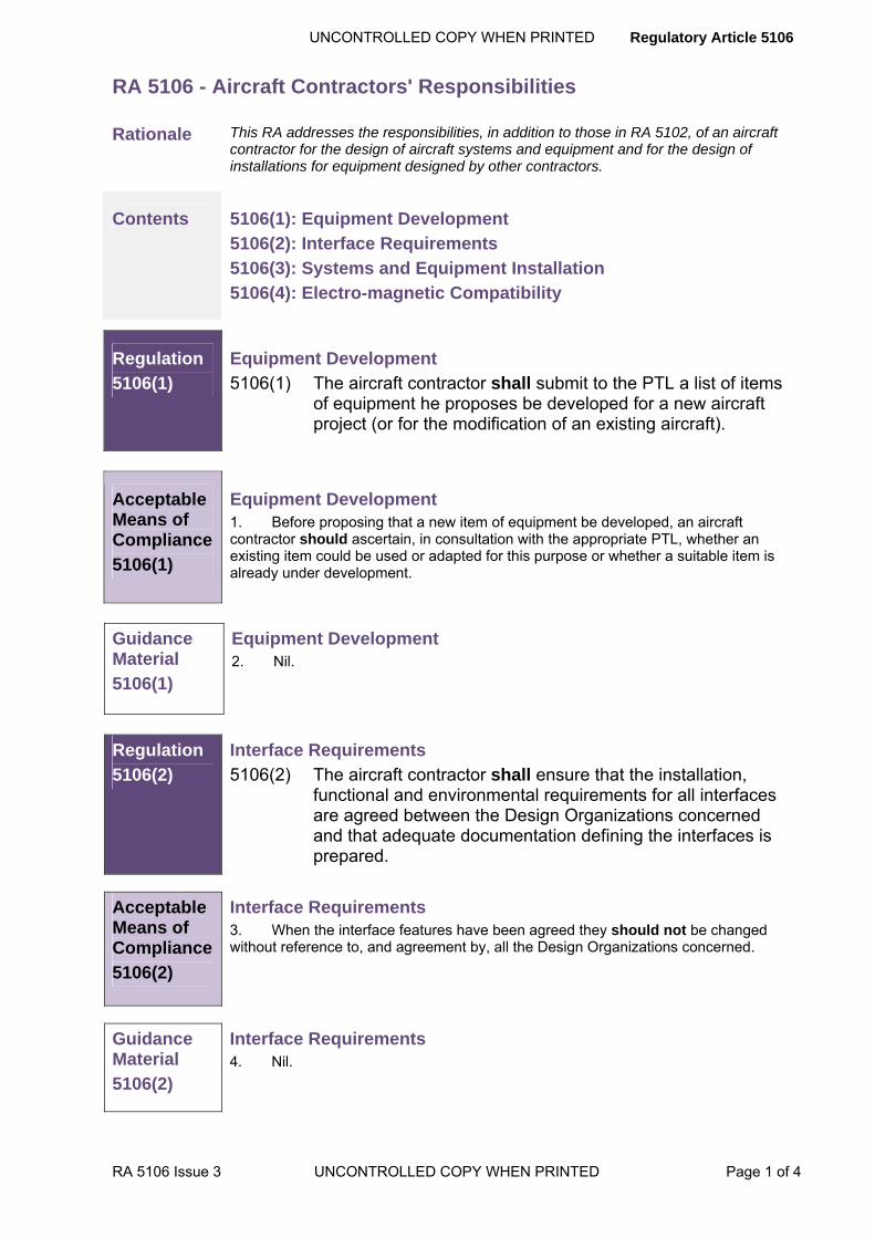
UNCONTROLLED COPY WHEN PRINTED Regulatory Article 5106
RA 5106 Issue 3 UNCONTROLLED COPY WHEN PRINTED Page 1 of 4
RA 5106 - Aircraft Contractors' Responsibilities
Rationale This RA addresses the responsibilities, in addition to those in RA 5102, of an aircraft contractor for the design of aircraft systems and equipment and for the design of installations for equipment designed by other contractors.
Contents 5106(1): Equipment Development
5106(2): Interface Requirements
5106(3): Systems and Equipment Installation
5106(4): Electro-magnetic Compatibility
Regulation
5106(1)
Equipment Development 5106(1) The aircraft contractor shall submit to the PTL a list of items
of equipment he proposes be developed for a new aircraft project (or for the modification of an existing aircraft).
Acceptable Means of Compliance
5106(1)
Equipment Development 1. Before proposing that a new item of equipment be developed, an aircraft contractor should ascertain, in consultation with the appropriate PTL, whether an existing item could be used or adapted for this purpose or whether a suitable item is already under development.
Guidance Material
5106(1)
Equipment Development 2. Nil.
Regulation
5106(2)
Interface Requirements 5106(2) The aircraft contractor shall ensure that the installation,
functional and environmental requirements for all interfaces are agreed between the Design Organizations concerned and that adequate documentation defining the interfaces is prepared.
Acceptable Means of Compliance
5106(2)
Interface Requirements 3. When the interface features have been agreed they should not be changed without reference to, and agreement by, all the Design Organizations concerned.
Guidance Material
5106(2)
Interface Requirements 4. Nil.

Regulatory Article 5106 UNCONTROLLED COPY WHEN PRINTED
Page 2 of 4 UNCONTROLLED COPY WHEN PRINTED RA 5106 Issue 3
Regulation
5106(3)
Systems and Equipment Installation 5106(3) The aircraft contractor shall be responsible for ensuring that
the design of a particular system or equipment is to the minimum requirements of that system or equipment contractor. The aircraft contractor shall also be responsible for the design of the installation of electronic equipment.
Acceptable Means of Compliance
5106(3)
Systems and Equipment Installation 5. For engine installations:
a. For turbo-jet engines, the engine Design Organization should normally be responsible for the design of jet pipes in agreement with the aircraft contractor. b. For turbo-propeller engines, the aircraft contractor should normally be responsible for the design of exhaust pipes in agreement with the engine Design Organization.
c. Any departure from these arrangements should be agreed at the engine installation advisory design conference.
6. For electronic installations the contractor should demonstrate, to the satisfaction of the Aircraft PTL that the completed installation meets the specified requirements.
7. For automatic flight control systems the aircraft contractor should conduct flight testing of the aircraft under automatic flight control to demonstrate that the performance and safety of the installation as a whole meets the relevant requirements.
8. For personal supply systems for aircrew the aircraft contractor should provide personal supply systems up to the aircraft/seat connections where ejection seats are fitted, or to the aircraft/man connection in other cases. The aircraft contractor should also ensure that personal supply systems are compatible with the Aircrew Equipment Assembly (AEA) for the aircraft, and through ground and flight tests demonstrate that the performance and safety of the installation meet the requirements.
9. For electrical installations the aircraft contractor should demonstrate to the MOD Aircraft PTL that the completed electrical installation meets the specified requirements.
10. For compass installations, the contractor should provisionally agree which types of compasses are to be fitted and their physical positions at the mock-up conference, and should ensure that the positioning of other equipment and cable layouts meet DefStan 00-970 requirements. The contractor should not change the type or position of a compass provisionally agreed by the mock-up conference without written authority.
11. For armament installations the aircraft contractor should:
a. Submit through the MOD PTL to ►DSA-MAA-Cert-DepHd◄ its proposals for the general layout of the installation and for the selection or development of major items of armament carriage, control and release equipment and special-to-type ground support equipment (RA 5200 series regulations).
b. Demonstrate to the satisfaction of ►DSA-MAA-Cert-DepHd◄ that::
(1) The design of the installations complies with the requirements of the relevant particular and general specifications (e.g. Armament Design Memoranda and DEF STAN 00-970).
(2) The electronic and electrical circuits are adequately protected from radiated electrical energy in the Service environment (RA 5200 series regulations).
(3) Any environmental limits on armament stores when fitted to the aircraft are not exceeded on the ground or in flight.
UNCONTROLLED COPY WHEN PRINTED Regulatory Article 5106
RA 5106 Issue 3 UNCONTROLLED COPY WHEN PRINTED Page 3 of 4
Acceptable Means of Compliance
5106(3)
12. For explosive devices the aircraft contractor should:
a. If proposing to use an electro-explosive device (EED) in an aircraft, either during development or by modification action, as early as possible consult ►DSA-MAA-Cert-DepHd◄
b. Use an existing EED, or a development thereof, whenever possible.
c. Demonstrate the efficiency and safety of the EED-based system.
13. For guided weapons systems the aircraft contractor should submit through the . PTL to the MOD Air Launched Munitions (ALM) PTL the proposals for the general layout of the installation, demonstrating:
a. To the satisfaction of the Aircraft and ALM PTLs, that the design of the installation complies with the requirements of relevant particular and general specifications.
b. To the satisfaction of ►DSA-MAA-Cert-DepHd◄, that the electrical circuits are adequately protected from radiated electrical energy in the Service environment.
c. To the satisfaction of PTL that any environmental restrictions on the missile are not exceeded on the ground or in flight.
Guidance Material
5106(3)
Systems and Equipment Installation 14. The term 'automatic flight control system' covers any combination of powered flying control/autopilot/auto-stabiliser.
Regulation
5106(4)
Electro-magnetic Compatibility 5106(4) The aircraft contractor shall demonstrate to the satisfaction
of the PTL that all systems will operate, with adequate safety margins, without malfunction or degradation of performance, in the electro-magnetic environment corresponding to the operational one.
Acceptable Means of Compliance
5106(4)
Electro-magnetic Compatibility 15. The aircraft contractor should demonstrate by ground and flight trials as agreed with the PTL, systems operation, safety margins, and performance, in the electro-magnetic environment corresponding to the operational one.
Guidance Material
5106(4)
Electro-magnetic Compatibility 16. The Aircraft Equipment Installation Information (AEII) or Radio Installation Memorandum (RIM) (RA 5200 series regulations) provides information for use in the design of equipment installations.

Regulatory Article 5106 UNCONTROLLED COPY WHEN PRINTED
Page 4 of 4 UNCONTROLLED COPY WHEN PRINTED RA 5106 Issue 3
Intentionally Blank for Print Pagination
Uncontrolled copy when printed Regulatory Article 5107
RA5107 Issue 2 Uncontrolled copy when printed Page 1 of 4
RA5107 – Aircraft Repair Schemes
‘This RA completely revised at Issue 2: no amendments marked within the text.’
Rationale During the design and development of materiel, consideration must be given to the probable need for repairs. At entry into Service of an aircraft, the Topic 6 of the Service Air Publication (AP), contains details of standard repairs, sometimes referred to as repair instructions, and identifies those parts of the aircraft where reference to the Design Organization (DO) is necessary before repair is undertaken. Subsequent additions may be made to the Topic 6 as a result of experience and changes in design. Schemes may also be required for the repair of damage to aircraft where the use of a standard repair would be inappropriate.
Contents 5107(1): Service Design Organization (SDO) Approval 5107(2): SDO Repair Schemes 5107(3): Design Organization (DO) Repair Schemes
Regulation
5107(1)
Service Design Organization (SDO) Approval 5107(1) The Aircraft Project Team Leader (APTL) shall ensure that
the SDO holds an extant approval from MAA under the Design Approved Organizations Scheme (DAOS) covering the relevant scope of activities.
Acceptable Means of Compliance
5107(1)
1. The PTL should:
a. Seek assurance of the SDO’s extant DAOS approval.
b. Enable a direct interface between the SDO and the DO for the availability of appropriate design data and the timely provision of design advice when requested by the SDO.
2. SDO repair schemes should be individually identified to distinguish them from DO repair schemes.
3. The SDO should have the appropriate design data and staff to design and conduct airworthy repair schemes.
4. The SDO should inform the PTL in the event of any lapse in its DAOS approval.
Guidance Material
5107(1)
5. For the purpose of this RA, Repair is defined as action taken to restore the static strength, stiffness, fatigue life and airworthiness of a faulty item to the levels of the original design without replacing the faulty item. The term 'repair scheme' will be taken to include 'repair instructions', but excludes instructions for minor repairs within the scope of the AP Topic 6 authorized at a Service Operating Unit. 6. The Service Departments have established design organizations, under Service authority, which may design repair schemes.
Regulatory Article 5107 Uncontrolled copy when printed
Page 2 of 4 Uncontrolled copy when printed RA5107 Issue 2
Guidance Material
5107(1)1
7. An up-to-date list of approved organisations may be obtained from the DAOS website at: http://www.daos.dii.r.mil.uk/. The SDO may request that extant approval is recorded routinely at platform Structural Integrity Working Groups in order to comply with this RA. 8. The DO may be requested, by the SDO, to supply design data or advice. The arrangements for the supply of such data will be negotiated, by the PTL, for each project/contract to take account of the data required and the contractual arrangements under which the design data was originally produced. 9. Airframe Record Card sanctions are recorded by the aircraft custodian in accordance with task clearance certificates.
10. The recognition of a SDO’s design capability reinforces the requirement to maintain airworthiness and emphasises the responsibility of the SDO to ensure the airworthiness of any repair scheme it designs.
Regulation
5107(2)
SDO Repair Schemes 5107(2) The SDO shall advise the APTL where, following the
incorporation of a repair scheme, either the static strength, stiffness, fatigue life and airworthiness would not be restored to the levels of the original design.
Acceptable Means of Compliance
5107(2)
11. Any repair scheme designed by a SDO should restore the original structural designer’s intent.
12. The SDO should respect any extant design limits and comply with the following requirements:
a. The SDO should notify the PTL where an Aircraft Release to Service (RTS) limitation may be necessary following the incorporation of a Service approved repair scheme.
b. Where the aircraft structure is affected, or where there is repair of equipment or systems in an aircraft, any limitations prescribed by the Aircraft DO or PT for structure, aerodynamics, weight, centre of gravity, and systems (including software) should be respected. Designs should not transgress such limitations without the written technical agreement of the Aircraft DO for the aircraft concerned.
c. Arrangements should exist for all SDO repair schemes, where technical advice is required or as defined by part (b) above, to be passed to the DO. The DO should provide advice as to whether or not the proposed repair transgresses the prescribed design limitations.
d. The SDO should seek the written approval of the PTL to conduct any repair where the Aircraft DO advises that prescribed design limitations will be transgressed.
13. In designing aircraft repairs the SDO should comply with the following requirements:
a. The DO should be consulted if the repair scope extends to any restricted structure (such as primary VITAL/SSI) or components for which no valid precedent or DO Repair Instruction exists.

Uncontrolled copy when printed Regulatory Article 5107
RA5107 Issue 2 Uncontrolled copy when printed Page 3 of 4
Acceptable Means of Compliance
5107(2)
b. A complete list of all repair schemes, and consequently changes to the aircraft build standard, should be forwarded to the Aircraft PT for the aircraft affected, for configuration management purposes and maintenance of any DO design records.
c. Consideration should be made as to whether the Service approved repair scheme has a sufficiently wide application to be included in the Air Publications (AP) Topic 6. 14. The repair should be justified by the SDO’s relevant task documentation and any design stress note.
Guidance Material
5107(2)
15. SDO repair schemes which restore the original structural designer’s intent inherently meet the full load spectrum of the aircraft’s design, as defined by regulation such as Def-Stan 00-970. A repair scheme is not an aircraft modification and therefore a full safety case, iaw Def-Stan 00-56, is not required in order to substantiate the repair’s structural integrity and airworthiness.
16. Any change in Mass or Centre of Gravity due to the installation of a repair scheme is delegated to the Aircraft Custodian for action within the Aircraft’s Log Book.
17. The Service DOs for Aircraft Structural Repair do not undertake repairs to Systems or Software.
18. Not transgressing prescribed design limitations is taken to mean, unless the Aircraft PT explicitly details a separate definition:
a. That the SDO has not worked on restricted components (such as primary VITAL/SSI) without any non-divergent application of the original designer’s repair instructions.
b. That the repair provides effective restoration of structural integrity (ie static ultimate load), without under or over stiffening, and therefore the aircraft release is unaffected.
c. That the repair is durable for the remaining life of the airframe, or for an explicitly specified duration where operationally necessary.
d. That the SDO holds sufficient design information to scheme an airworthy repair scheme.
e. That the SDO has not exceeded its authority under its DAOS certification.
19. The precedence of any repair is valid if an identical repair may be applied, without divergence, to identical structure.
20. The Request for Categorisation signal, raised by the aircraft custodian in accordance with RA4405, authorises the SDO to scheme and conduct any repair. Business Agreements between the SDO’s parent TLB and DE&S/FLCs may additionally contain explicit approval for SDOs to undertake aircraft work.
21. The DO has no responsibility for the accuracy or effectiveness of Service approved repair schemes.

Regulatory Article 5107 Uncontrolled copy when printed
Page 4 of 4 Uncontrolled copy when printed RA5107 Issue 2
Regulation
5107(3)
Design Organization Schemes 5107(3) The DO shall advise the APTL where, following the
incorporation of a repair scheme, either the static strength, stiffness, fatigue life and airworthiness would not be restored to the levels of the original design.
Acceptable Means of Compliance
5107(3)
22. The Aircraft PTL should consider the implications on the use of aircraft with a repair scheme embodied that does not restore static strength, stiffness, fatigue life and airworthiness to the original design levels, in order that consideration can be given to the need for an amendment to the Aircraft RTS.
23. When the Service operating a particular aircraft type requires a repair scheme which is not catered for in the AP Topic 6, and the repair scheme should not to be prepared by a SDO; a request for a repair scheme should be passed to the DO. Consideration should be given to the need for the inclusion of the repair scheme in the AP Topic 6.
Guidance Material
5107(3)
24. A list of DO approved repair schemes which have not been included in AP Topic 6 will be retained in a master list forming part of the design records.
UNCONTROLLED COPY WHEN PRINTED Regulatory Article 5201
RA 5201 Initial Issue UNCONTROLLED COPY WHEN PRINTED Page 1 of 4
RA 5201 - Interchangeability
Rationale This RA addresses the design records for interchangeability, for the assurance of interchangeability, and for the provision and maintenance of interchangeability media. Unless otherwise indicated, for the purpose of this RA, the term interchangeability includes fully interchangeable and replaceable.
Contents 5201(1): Interchangeability of Materiel
Regulation
5201(1)
Interchangeability of Materiel 5201(1) All items of materiel having the same part number shall be
either ‘Fully Interchangeable’ or, for agreed airframe spares, shall be ‘Replaceable’ with some alteration when installed.
Acceptable Means of Compliance
5201(1)
1. The contractor responsible for the manufacture of original fit items or spares should ensure interchangeability in accordance with the requirements of the design and the interchangeability media. The contractor should maintain interchangeability media so that there is no deviation from the approved standard during their period of use.
2. Information on interchangeability should be inserted in the design records. Formal assurance of interchangeability should be provided for some items where the manufacturing methods and design tolerances defined in the design records do not provide adequate assurance, due to the complexity of the item and its physical and functional interfaces.
3. The Design Organization (DO) for the aircraft, engine, guided weapon or electronic system should be responsible for:
a. The overall interchangeability requirements and documentation. b. Ensuring that interface proposals produced by the DO are compatible with those proposed by any other DO. c. The provision of copies of information on interchangeability to any interfacing DO.
4. When a design is modified, the DO for the modification should be responsible for:
a. the introduction of changes to the interchangeability information in the design records and to the interchangeability media, concurrently with the issue of new or modified drawings. b. the supply of information to change all sets of interchangeability information and media where more than one standard of design or interchangeability media co-exist.
5. Where control of the interchangeability of items cannot be achieved directly from the drawings the DO should provide, concurrently with the manufacturing drawings and prior to the manufacture of tooling, interchangeability data sheets, or interchangeability control drawings.
6. The data sheets should show: a. Characteristics and tolerances which may affect physical or functional interchangeability related to their counterpart features. b. The tolerances upon dimensions and attachments of all assemblies which are likely to be held as spares, including clearances necessary to ensure that no part of a movable component will foul any adjacent component.

Regulatory Article 5201 UNCONTROLLED COPY WHEN PRINTED
Page 2 of 4 UNCONTROLLED COPY WHEN PRINTED RA 5201 Initial Issue
Acceptable Means of Compliance
5201(1)
c. Information as at (b) for the interfaces between sub-assemblies. d. Details of any shims and bushes to be used at rigid attachments. e. Cross-references to the data sheets for interface items.
7. As early as practicable in the development programme the DO should prepare an interchangeability list for those items which require assurance of interchangeability. The list should be agreed with the PTL.
8. The interchangeability list should give the description of the item and the basic drawing or part number.
9. The DO should prepare an interchangeability schedule for all items on the interchangeability list.
10. The interchangeability schedule should provide the following information in respect of each item on the interchangeability list:
a. Part number, description and details in order to identify the physical or functional features affecting interchangeability and mating interfaces. b. Reference to the applicable interchangeability data sheet or interchangeability control drawing, production acceptance test specification and interface specification where it exists. c. Details of the method for the control and inspection of each interchangeability feature. These should include gauge and/or test equipment identification where applicable, and inspection and test procedures. d. Details of any alterations or adjustments, either physical or functional, which may be necessary to ensure satisfactory assembly or functioning when full interchangeability cannot otherwise be achieved. e. References to interfaces where other DO are concerned. f. Reference to interfaces with other Service materiel.
11. The DO's proposals for assuring interchangeability of items should be available for audit by a PTL representative as soon as practicable in the development programme.
12. Interchangeability of production standard and spares items, including the use of interchangeability media, should be demonstrated to the PTL, and/or any interfacing DO, if required by contract.
13. Where replaceability, rather than interchangeability, is acceptable the work required on fitment of the spare should be as little as possible consistent with the type of repair envisaged. The standard should be arrived at by consultation between the DO and PTL, and should be confirmed and defined at the spares provisioning committees for production aircraft.
14. An interchangeability meeting should be arranged by the PTL at which any proposed exemptions against the requirements will be discussed. Where practicable this meeting should be held prior to acceptance of the relevant contracts.
15. Not later than 14 days before the meeting, the DO should supply the PTL with 12 copies of a list of items for which interchangeability exemptions are required. For pre-production batch aircraft, the list should also indicate the progressive dates by which interchangeability will be achieved. At the meeting, the list of major airframe components and assemblies should be available.
16. As soon as possible after the meeting, an interchangeability exemption list should be issued by the PTL showing those items which have been agreed will not need to be interchangeable. The extent of the exemption should be defined, and a brief statement of the reason for non-compliance will be given. Further meetings should be held to discuss proposals for addition and amendments which the contractor may submit . After the final meeting, all items not shown on the interchangeability exemption list should be deemed to be interchangeable.

UNCONTROLLED COPY WHEN PRINTED Regulatory Article 5201
RA 5201 Initial Issue UNCONTROLLED COPY WHEN PRINTED Page 3 of 4
Guidance Material
5201(1)
17. Jigs, fixtures, references and other tools, known as interchangeability media, are required to ensure interchangeability is maintained during manufacture.
18. The original DO for an aircraft, engine, guided weapon, or electronic system is responsible for the information in the design record to assure interchangeability, and for the supply of interchangeability media. Where a design is subsequently modified, the DO of the modification is responsible, in collaboration with the original DO, for the additional information in the supplementary design record to assure interchangeability, and for the supply of interchangeability media for the altered design. Where contracts for spares are to be awarded to a manufacturing contractor using drawings and specifications obtained by MOD from a DO, the manufacturing contractor will normally be supplied through the PTL with the appropriate interchangeability media.
19. When a design is modified, the DO for the modification must be responsible for the introduction of changes to the interchangeability information in the design records and to the interchangeability media, concurrently with the issue of new or modified drawings. The supply of such information may require liaison with the DO for the aircraft, engine, guided weapon or electronic system, or with a manufacturing contractor responsible for the supply of spares.

Regulatory Article 5201 UNCONTROLLED COPY WHEN PRINTED
Page 4 of 4 UNCONTROLLED COPY WHEN PRINTED RA 5201 Initial Issue
Intentionally Blank for Print Pagination

UNCONTROLLED COPY WHEN PRINTED Regulatory Article 5202
RA 5202 Initial Issue AIL1 UNCONTROLLED COPY WHEN PRINTED Page 1 of 38
RA 5202 – Military Flight Test Permit (MFTP)
Rationale An approved Military Flight Test Permit (MFTP) is required before flight tests may be undertaken.
Contents 5202(1): Scope of Military Flight Test Permit (MFTP)
5202(2): MFTP Procedure
Regulation
5202(1)
Scope of Military Flight Test Permit (MFTP) 5202(1) The authorization of specified flight(s) of a Military Air System
shall be conducted using a MFTP if all of the following conditions exist: a. A valid Certificate of Usage does not exist. b. Where the design standard is not reflected in an extant
RTS or flying outside the service environment ie outside the recognised and agreed flight envelope.
Acceptable Means of Compliance
5202(1)
1. Nil
Guidance Material
5202(1)
2. The requirement for a Declaration of Compliance (D of C) may be satisfied by provision of the Certificate of Design subject to the Applicant demonstrating that all the requirements of Appendix C have been satisfied.
3. The European Technology Acquisition Programme (ETAP) participating nations of France, Germany, Italy, Spain, Sweden and the United Kingdom have agreed a common approach to producing MFTPs.
Regulation
5202(2)
MFTP Procedure 5202(2) Before flight testing of a Military Air System can be
undertaken, the Applicant shall request the issue of a MFTP and shall supply all the required supporting evidence to the TAA.

Regulatory Article 5202 UNCONTROLLED COPY WHEN PRINTED
Page 2 of 38 UNCONTROLLED COPY WHEN PRINTED RA 5202 Initial Issue AIL 1
Acceptable Means of Compliance
5202(2)
MFTP Procedure 4. Applications for a MFTP should be in the format at Appendix A.
5. The signatory for the Design Organization on the MFTP Application should be approved for the purpose under Design Approved Organisation Scheme (DAOS).
6. In support of the request for a MFTP, the Applicant should submit a signed Declaration of Compliance (D of C) to the TAA. The D of C should include evidence that the Military Air System has been inspected and tested as required to determine that it is airworthy and that no features or characteristics make it unsafe for its intended use. The content of a D of C is defined in Appendix C.
7. In addition to the D of C, the Applicant should provide evidence that they have arrangements in place for demonstrating that the Military Air System is fit for flight.
8. The Applicant should apply to the TAA for a new or amended MFTP when there are changes to the evidence contained in the D of C relating to: limitations, airworthiness, safety or configuration.
9. If changes to the data attached to the MFTP are required then the change to the MFTP should be authorized and issued by the TAA (Amendment Statement (Appendix B) which only authorizes the change to the MFTP and does not authorize the flight).
10. An historical hard copy record should be maintained of the original MFTP and subsequent Amendments.
MFTP Procedure – Particular Cases 11. Where the Applicant is not the original Military Air System design organization the Applicant should include, in the D of C submitted in support of the MFTP, or any amendment thereto, evidence of review by the original Military Air System design organization which confirms that the airworthiness and safety of the design have not been adversely affected.
12. For Flight Tests with an airborne armament store or air launched guided weapon system:
a. The Applicant should provide evidence, in the D of C submitted in support of the MFTP, or any amendment thereto, that the airborne armament store or air launched guided weapon design organization has provided the necessary evidence with respect to any carriage, firing, launch/release or jettison limitations.
b. The Applicant is responsible for, and should demonstrate, that due account of the limitations has been taken in the design, testing and operation of the Military Air System.
Determination of Flying Limitations 13. The flight limitations specified in the D of C which forms a part of the MFTP should be determined on the principles set out in the appropriate National standard for Military Air System design.
14. The flight limitations should take account of the qualifications and competence of the air vehicle pilot, flight crew and flight test engineers as appropriate.
15. If at any time after an MFTP has been issued, the Applicant becomes aware of evidence that necessitates a restriction on existing limitations, the Applicant should immediately advise:
a. The TAA and
b. The Military Air System design organization if different to the Applicant.
16. If urgency dictates an SFI should be raised (see RA 5220). The Applicant should then request a new or amended MFTP from the original TAA.
17. Where the restriction may affect other operators of similar type Military Air

UNCONTROLLED COPY WHEN PRINTED Regulatory Article 5202
RA 5202 Initial Issue AIL1 UNCONTROLLED COPY WHEN PRINTED Page 3 of 38
Acceptable Means of Compliance
5202(2)
Systems, the Applicant should also make arrangements for them to be informed via the appropriate regulatory authorities.
MFTP Distribution 18. Following signature by the TAA, the original MFTP and any amendments and revisions thereto, should be returned to the Applicant.
19. The Applicant should distribute copies of the MFTP and any amendments and revisions thereto to the Military Air System operators and other agencies involved in the conduct of the associated flight testing of the Military Air System as required.
Service Derivative of a Civil Aircraft 20. Where the advice of the Civil Aviation Authority (CAA) is required, the applicant should supply a further copy of the MFTP to the CAA to obtain their comment.
Guidance Material
5202(2)
MFTP Procedure 21. An MFTP is specific to the individual Military Air System identified upon the permit by serial number.
22. The MFTP must be signed in accordance with this procedure before the first flight of the proposed test programme can start. The MFTP states the Definition, Airworthiness, Safety and Limitations of the Military Air System to be tested/ flown. The MFTP will be in the form of Appendix A to this RA.
23. On receipt of the request the TAA will review the evidence supplied and once satisfied the MFTP will be signed by the TAA’s authorized representative.
24. Following an occurrence, the Applicant or the TAA may withdraw the MFTP. The Applicant or the TAA, as appropriate, will advise all other involved parties including the Military Air System operator, the Government Quality Assurance Representative (GQAR) and the Government Project Office.

Regulatory Article 5202 UNCONTROLLED COPY WHEN PRINTED
Page 4 of 38 UNCONTROLLED COPY WHEN PRINTED RA 5202 Initial Issue AIL 1
APPENDIX A
MILITARY FLIGHT TEST PERMIT FOR A MILITARY AIR SYSTEM
Security Classification Reference:………………
1. This permit is issued in accordance with Military Flight Test Permit Procedure
MILITARY AIR SYSTEM: VERSION/MARK:
SERIAL No: REGISTRATION MARK:
SPECIFICATION No:
CONTRACT OR LOAN AGREEMENT No:
SUBJECT OF CONTRACT:
ENGINE TYPE:
PROPELLER (if applicable):
2. Permission is hereby given for flights, within the limitations of reference1…………… attached to this permit, from an approved location, for the purpose of flight by an authorized pilot, as permitted by the said reference current amendment.
3. The design of the Military Air System is represented by the Configuration Status Record, the identification and issue of which is shown in the statement of design limitations reference2 ………… attached to this permit
NOTE: This permit does not constitute an authority to fly the Military Air System unless the requirements for assurance as to the fitness for flight of the Military Air System have been satisfied
For Design Organization (Insert name of Design Organization)
Date Signed (Authorized Signatory) Name
Applicant:
Manufacturer:
Support Contractor Operator
For TAA:
Date Signed Name
Valid Until Date:
Note: Changes affecting the limitations in the documents referenced at clauses 2 or 3 above must be agreed by endorsement of an Amendment Statement in the form of Appendix B, or re-issue of this permit.
1 The document referred to shall as a minimum address all aspects of flying limitations 2 The document referred to shall as a minimum address all aspects of design limitations

UNCONTROLLED COPY WHEN PRINTED Regulatory Article 5202
RA 5202 Initial Issue AIL1 UNCONTROLLED COPY WHEN PRINTED Page 5 of 38
Reference……………..
Amendment Record Sheet
A/L No.
Amendment Statement Ref.
Design or Flight Limitations and Parts
affected
Incorporated by Date Incorporated
1
2
3
4
5
6
7
8
9
10
11
12
13
14
15
16

Regulatory Article 5202 UNCONTROLLED COPY WHEN PRINTED
Page 6 of 38 UNCONTROLLED COPY WHEN PRINTED RA 5202 Initial Issue AIL 1
APPENDIX B
AMENDMENT STATEMENT TO MILITARY FLIGHT TEST PERMIT FOR A MILITARY AIR SYSTEM
Security Classification
Reference:…………..
FOR CHANGES TO DESIGN OR FLIGHT LIMITATIONS
1. Amendment No ... to the Design/Flying* limitations contained in MFTP for a Military Air System Reference …………… Issue ………..
2. This amendment is issued in accordance with Military Flight Test Permit Procedure. This amendment does not of itself authorize flight trials but only authorizes amendment to the appropriate MFTP.
Military Air System Type ……………………………… Serial No …………..
Contract Number …………………………………..
3. Brief description of alterations to design/flying limitations and/or approved pilot (with list of associated drawings and reason for the amendment attached, if necessary).
4 (a) *Remove pages .... from Design/Flying* limitations attached to the above MFTP.
(b) *Insert attached revised*/new* pages …. into Design/Flying* limitations of the above MFTP. (c) *Revise the authorized category of pilot by adding to*/deleting from* MFTP, Flying Limitations in accordance with instruction in Paragraph 3 above. (d) Record this amendment on the MFTP amendment record sheet.
*delete as appropriate
Date Signed Name
For Design Organization
Name of Applicant
Date Signed Name
For TAA

UNCONTROLLED COPY WHEN PRINTED Regulatory Article 5202
RA 5202 Initial Issue AIL1 UNCONTROLLED COPY WHEN PRINTED Page 7 of 38
APPENDIX B AMENDMENT STATEMENT TO MFTP
Explanatory Notes
1 This certificate is to be used to cover an amendment to the design or flying limitations contained in a MFTP.
2 This amendment must be promulgated by issue of new or the replacement and/or withdrawal of old pages as instructed by paragraph 4 of this Certificate. To assist the user, a vertical line must appear in the margin against those parts of the existing limitations which have been altered by current amendments.
3 The originator must ensure that the correct security markings are given to this form and the amended page(s) which it covers.
4 When this form is used to amend a MFTP containing Specific Units (e.g. Imperial Units), the use of those Specific Units is to be continued.

Regulatory Article 5202 UNCONTROLLED COPY WHEN PRINTED
Page 8 of 38 UNCONTROLLED COPY WHEN PRINTED RA 5202 Initial Issue AIL 1
APPENDIX C DECLARATION OF COMPLIANCE CRITERIA
The Declaration of Compliance is a signed statement of compliance (see Annex 1 below) which covers and certifies the integrity of a list of the supporting evidence by reference number and issue status, the “D of C documentation”, which provides the following evidence as a minimum:
a. System Definition a.1 System Specification
Defines the performance, airworthiness and safety requirements a.2 System Design Requirements
includes the Qualification and Certification Basis, a.3 System Descriptions
Short narrative description of the system(s) to be tested. The level of detail required will be dependent on the complexity of the system(s) to be tested and may refer to other more explicit document(s).
a.4 System Configuration Defines the design configuration (including software and interfaces) of the system.
a.5 System configuration changes introduced by modification Narrative statement of the system changes introduced since previous MFTP issue.
a.6 System Qualification Documentation A list of reports on all analysis and tests conducted to show compliance with the system specification (including software)
a.7 System Safety Analysis a.7.1 The analysis must demonstrate that the design meets the required level of
safety for the proposed flight(s). An overall system cumulative probability of catastrophic technical failure must be provided.
a.7.2 The analysis must also demonstrate that the design meets the required level of safety for ground operation (for example maintenance).
a.8 Design Limitations a.9 Flying Limitations a.10 System Technical Limitations list
List identifying the technical limitations (performance) that relate to the proposed tests. a.11 System Exceptions list
List identifying the exceptions against the certification basis that have yet to be satisfactorily demonstrated.
a.12 Limiting Conditions List List identifying the limiting system external conditions for the proposed tests (e.g. VMC only, no rain, no cross wind >x knots etc.)
b. System Review reports b.1 System Airworthiness Report
Report of the results from the design organization’s independent airworthiness review (independent checking function) of the evidence supporting the system definition. The checking function must be independent from the design activities.
b.2 Report from reviews of the System definition comprising: b.2.1 Report on System Design Reviews (SDR), including airworthiness aspects
and report of performed system safety analysis. b.2.2 Report on the Configuration Audit (CA)3. The CA will normally be undertaken
throughout the design and build process in conjunction with the NMCA and will be in 2 parts:
3 This satisfies the national requirement for a Statement or Certificate of Conformity for each Military Air System

UNCONTROLLED COPY WHEN PRINTED Regulatory Article 5202
RA 5202 Initial Issue AIL1 UNCONTROLLED COPY WHEN PRINTED Page 9 of 38
i. a Physical Configuration Audit (PCA) to verify that the as-built configuration of the Military Air System meets the documented design standard for the requirements of the proposed test(s) and ii. a Functional Configuration Audit (FCA) to verify the CIs and systems performance against the approved configuration documentation and determine whether the Military Air System design meets the functional requirements for the proposed test(s).
c. Results from ground test and/or previous flight tests. d. Previous experience of the system. e. Flight test programme to which this request refers
e.1 Definition of the system to be tested. e.2 Definition of the actual test activities and test flights to be performed. e.3 Test objective(s). e.4 Reference to all limitations and exceptions (see a8 – a11) e.5 A final risk evaluation for the complete program demonstrating suitable
mitigation in place to achieve an acceptable level of residual risk. f. Maintenance Instructions g. Operating Instructions h. Operator’s organization and experience
h.1 A definition of the organization to operate the system under supervision of the TAA
h.2 A short description of the organization which will operate the system and a statement as to their competence.
h.3 A definition of key persons and their qualifications and experiences required for their tasks during the flight testing.
i. Other information nationally required
Note: The above list is not exhaustive and in addition the operator will be required to prepare an operating safety argument in support of the use of airfields, ranges and test facilities for agreement with the relevant authority.
The operating safety argument must address separately the airfields and test/flight areas including access and egress routes to be used covering, as a minimum, the following:
a. emergency conditions (crash, emergency landing and escape).
b. all other conditions and environments that may affect the safety of the proposed flight(s) (for example EMC/I, flight profile, weather, multiple aircraft involved in the test etc).
c. risk to other air vehicles.
d. risk to people on the ground and measures taken to reduce that risk.
e. risk to 3rd party property and measures to reduce that risk.
f. go/no go statement based on the risk values estimated above.

Regulatory Article 5202 UNCONTROLLED COPY WHEN PRINTED
Page 10 of 38 UNCONTROLLED COPY WHEN PRINTED RA 5202 Initial Issue AIL 1
ANNEX 1 to APPENDIX C DECLARATION OF COMPLIANCE FOR A MILITARY AIR SYSTEM
Reference No Issue No Military Air System Contract No D of C Documentation Reference Issue We, the designers of the above, hereby certify that:
With the exceptions and limitations stated in the above referenced D of C documentation.
The Military Air System above complies with the design airworthiness requirements of:
Specification Issue
Up to and including Amendment
Issued by
DESIGN SIGNATORIES
Recognised signatory for Design Recognised signatory for the Board Name: Name: Signature: Signature:
For (Design Organization) Date

UNCONTROLLED COPY WHEN PRINTED Regulatory Article 5202
RA 5202 Initial Issue AIL1 UNCONTROLLED COPY WHEN PRINTED Page 11 of 38
ANNEX A1 TO SECTION 2 APPENDIX A MILITARY FLIGHT TEST PERMIT
Design Limitations - Aeroplane
Definitions and Explanatory Notes
A1.1 Definitions
A1.1.1 Design Limit. A performance or operational extreme to which the aeroplane is designed, generally as required by the aeroplane specification.
A1.1.2 Basic Mass. The mass of the aeroplane excluding the crew, but including gases, unconsumable fuel and fluids, and all non-expendable equipment which is common to all roles.
A1.1.3 Equivalent Airspeed (EAS). EAS is defined as the product of the true speed and the square root of the relative air density.
A1.1.4 Basic Aeroplane. The term ‘basic aeroplane’ is used to define the aeroplane without external stores and removable external equipment.
A1.1.5 Aeroplane Configuration. The term ‘aeroplane configuration’ is used to refer to the shape that the aeroplane adopts according to the various arrangements of moveable structure such as undercarriage, flaps, airbrakes etc. which may be selected by the crew or extended automatically, and external stores. In this context, ‘clean’ is used to denote the aeroplane configuration existing with all movable structure retracted, and external stores removed.
A1.2 Explanatory Notes
A1.2.1 A detailed statement is required to indicate the basis on which the mass and centre of gravity data given in Annex A2, Section A2-2 have been determined (Load Sheet procedure in accordance with 5000 Series RAs).
A1.2.2 It must be noted that the limitations for the Aircrew Equipment Assembly (AEA) are functions of the aeroplane/equipment combination and cannot be defined for the equipment in general. The limitations must include, for example, the speed and height limits for which the ejection seat has been designed and the greatest altitude at which the AEA will give the pilot and crew protection if cabin pressure fails. Similar considerations apply to night vision goggles and nuclear, biological and chemical protection equipment.
A1.2.3 The originator must ensure that the correct security marking is given to this Annex.

Regulatory Article 5202 UNCONTROLLED COPY WHEN PRINTED
Page 12 of 38 UNCONTROLLED COPY WHEN PRINTED RA 5202 Initial Issue AIL 1
A1.2.4 The ‘International System’ of units (SI) must be used for new projects, except for altitude which will be given in feet. However where this form is used for existing aircraft for which Imperial Units were used the use of Imperial Units must be continued. Any change from Imperial Units to SI units must be clearly indicated.
A1.2.5 It is the DO’s responsibility to ensure that an attached list of documents defining the aeroplane includes any design office instructions which have the effect of varying any of the listed documents in a way which affects safety. When any design changes are subsequently made which affect the airworthiness of the main components, systems or installations, or which the DO considers to be essential for safety, an amendment to this list must be issued covering these changes and promulgated by the issue of replacement page(s) or instructions. Authorization of the amendment will be by an Amendment Statement in the form of Appendix B.
A1.2.6 Each sheet of the statement of design is to show the standard of its issue.

UNCONTROLLED COPY WHEN PRINTED Regulatory Article 5202
RA 5202 Initial Issue AIL1 UNCONTROLLED COPY WHEN PRINTED Page 13 of 38
ANNEX A2 TO SECTION 2 APPENDIX A MILITARY FLIGHT TEST PERMIT
Design Criteria - Aeroplane
A2.1 Introduction
A2.1.1 This summary defines the design parameters of significance to flight trials, and the data presented must cover such headings as are appropriate to the aeroplane under test. The sub-headings below must therefore be regarded as examples only, but they must include all limitations applicable to airworthiness.
A2.1.2 The limits are those to which the aeroplane has been designed and they must not be used as flight limitations. The limitations to be observed during flight trials are given in Annex A4.
A2.1.3 Updating or amendment of this Annex must be made under the cover of an Amendment Statement in the form of Appendix B.
A2.2 Mass and Centre of Gravity
A2.2.1 This must be presented via tables and figures defining the permissible mass/centre of gravity envelope, with the undercarriage up and down. The centre of gravity position must be quoted as a distance from a fixed datum and as a percentage of the Standard Mean Chord (SMC).
A2.2.2 The following values of mass must be defined. (where appropriate, these must include all types of runway surfaces from which the aeroplane is required to operate).
a) Design take-off.
b) Maximum normal take-off.
c) Maximum overload take-off.
d) Design combat.
e) Design landing.
f) Normal landing.
g) Maximum overload/emergency landing.
Lateral loading limits must also be defined.
A2.3 Design limits for basic aeroplane (without external stores)
A2.3.1 Design flight envelope
The design flight envelope for the ‘clean’ aeroplane must be presented in tabular and graphic form in terms of the variation of design speed (EAS) with altitude.

Regulatory Article 5202 UNCONTROLLED COPY WHEN PRINTED
Page 14 of 38 UNCONTROLLED COPY WHEN PRINTED RA 5202 Initial Issue AIL 1
A2.3.2 Maximum design speeds
Maximum design speeds must be tabulated for configurations or conditions, such as the following:
a) Undercarriage down and/or operating.
b) Airbrakes out and/or operating.
c) Flaps or other lift augmentation at all selectable settings.
d) Bomb doors open.
e) Wing sweep positions.
f) Cooling gills or vectoring nozzles at all selectable settings.
A2.3.3 Design manoeuvre limitations
These must be defined in a convenient form (preferably tabular and graphic) for the following conditions for the clean aeroplane:
a) Symmetric manoeuvres (as defined in Def Stan 00-970 Part 1, Section 3, Clause 3.3.
b) Rolling manoeuvres, including rolling pull out (as defined by Def Stan 00-970 Part 1, Section 3, clause 3.4 and supplement 09) or inertia cross coupling statement/diagram.
c) Maximum sideslip angles.
d) Maximum incidence and/or minimum speed.
e) Spinning manoeuvres.
f) Aerobatic manoeuvres.
Similar limitations must be defined with all lift augmentation/manoeuvre devices deployed, as appropriate.
A2.3.4 Design speeds subsequent to engine failure
These must be given, where they are critical, in terms of asymmetric loads and/or controllability (e.g. Vmcg, Vmca, Vmcl).
A2.3.5 Atmospheric limitations
a) Altitude.
b) Ambient temperature.
c) Humidity and precipitation.
d) Icing conditions.
e) Turbulence.
f) Maximum wind and crosswind components up to the maximum permitted asymmetric rolling moment, where applicable (e.g. for engine start, taxi, take-off and landing).
UNCONTROLLED COPY WHEN PRINTED Regulatory Article 5202
RA 5202 Initial Issue AIL1 UNCONTROLLED COPY WHEN PRINTED Page 15 of 38
A2.4 Design flight limits for aeroplanes with internal/external stores
A2.4.1 This section must present the design limits for the aeroplane with the required range of internal/external store configurations and/or all removable excrescences.
A2.4.2 The manner in which this data is presented will depend upon the range of stores configurations, but for each separate store configuration all applicable limitations as in clauses A2.2 and A2.3 above must be given, including release and jettison.
A2.5 Design undercarriage limitations
A2.5.1 Normal acceleration with undercarriage down.
A2.5.2 Maximum sink rates at touchdown as a function of the mass of the aeroplane.
A2.5.3 Runway conditions, Aircraft Classification Number (ACN) and/or Load Classification Number (LCN), California Bearing Ratio (CBR), surface type and contamination etc.
A2.6 Engine limitations (on aeroplane design)
This must give reference to the engine DO’s Technical Certificate and Flight Clearance Note which define the engine operating limitations.
A2.7 Miscellaneous system design limitations
Appropriate design limitations must be given for systems such as the following:
a) Wheels, tyres and brakes.
b) Brake parachute.
c) Arrestor hook and cable trampling.
d) Cabin and equipment conditioning.
e) Hydraulic systems.
f) Electrical systems.
g) Flying control and autostabilizer systems.
h) Stall warning system.
i) Autopilot and terrain following systems.
j) Head-up display.
k) Navigation and weapon aiming system.
l) Flight director(s).
m) Ice protection system.
n) Windscreen clearance and canopy.
Regulatory Article 5202 UNCONTROLLED COPY WHEN PRINTED
Page 16 of 38 UNCONTROLLED COPY WHEN PRINTED RA 5202 Initial Issue AIL 1
o) AEA, oxygen and anti-’g’ systems. (see Annex A1, clause A1.2.2).
p) Electronic countermeasures.
q) Onboard radar.
r) Emergency escape.
s) Electro-optic flying aids.
A2.8 Design limitation in respect of miscellaneous phase of flight/roles
a) In-flight refuelling.
b) Night flying.
c) Shipborne operations.
d) Use of special test equipment.
e) Use of armament systems.
f) Stores dropping.
g) Night vision goggles.
h) Nuclear, biological, chemical protection equipment.

UNCONTROLLED COPY WHEN PRINTED Regulatory Article 5202
RA 5202 Initial Issue AIL1 UNCONTROLLED COPY WHEN PRINTED Page 17 of 38
ANNEX A3 TO SECTION 2 APPENDIX A MILITARY FLIGHT TEST PERMIT
Flying Limitations - Aeroplanes
Definitions and Explanatory Notes
A3.1 Definitions
A3.1.1 Flying Limitations. A performance or operational extreme to which the aeroplane may be flown for test purposes, as recommended by the Design Organization.
A3.1.2 Basic Mass. The mass of the aeroplane excluding the crew, but including gases, unconsumable fuel and fluids, and all non-expendable equipment which is common to all roles.
A3.1.3 Indicated Airspeed (IAS) and Indicated Mach Number (IMN). IAS and IMN are defined as the instrument readings corrected for instrument error only. Pressure error correction curves for IAS and IMN will be given in documents referenced in Annex A4, clause A4.11.
A3.1.4 Basic Aeroplane. The term ‘basic aeroplane’ is used to define the aeroplane without external stores and removable external equipment.
A3.1.5 Aeroplane Configuration. The term ‘aeroplane configuration’ is used to refer to the shape that the aeroplane adopts according to the various arrangements of moveable structure such as undercarriage, flaps, airbrakes etc. which may be selected by the crew or extended automatically, and external stores. In this context, ‘clean’ is used to denote the aeroplane configuration existing with all movable structure retracted, and external stores removed.
A3.2 Explanatory Notes
A3.2.1 The scope of the Flying Limitations must not extend beyond the range of the tests conducted satisfactorily by the Contractor, or the conditions predicted by him to be satisfactory from considerations of the safety of the aeroplane. The PTL may give a more restrictive clearance, if he has reason to do so, e.g. he may restrict the maximum speed until certain phenomena have been fully investigated by the Contractor and/or MOD Establishment. Must values be given other than those obtained by flight test or, in the case of weights and CG positions by direct weighing, comment is to be made accordingly.
A3.2.2 It is the responsibility of the DO to ensure that in the event of dangerous flight conditions being encountered within the issued Flying Limitations, the limits affected are amended to prohibit flight in that region.
A3.2.3 A detailed statement is required to indicate the basis on which the mass and centre of gravity data given in Annex A4 have been determined.

Regulatory Article 5202 UNCONTROLLED COPY WHEN PRINTED
Page 18 of 38 UNCONTROLLED COPY WHEN PRINTED RA 5202 Initial Issue AIL 1
A3.2.4 If any of the flight limitations of Annex A4 are due to the Contractor’s assessment of handling qualities, this is to be stated and the symptoms described in a footnote or, where the volume of material requires it, in a separate Appendix.
A3.2.5 In considering the maximum speeds and normal accelerations to which the aeroplane has to be cleared for flight test purposes, reference must be made to the requirements of Def Stan 00-970, Part 1, Section 2, Clauses 2.2, and 2.7 The methods by which the limits are to be obtained are outlined in Def Stan 00-970, Part 1 Section 2 Supplement 09. In considering the maximum normal accelerations during manoeuvres involving combinations of roll and pitch, reference must be made to Def Stan 00-970 Part 1 Section 2 Supplement 09. Account must be taken of any inertia cross-coupling effects.
A3.2.6 In any particular flight test, the pilot must not deliberately exceed the limitations quoted. If any limitation is inadvertently exceeded the occurrence and its extent must be brought to the attention of the Design Organization, and the PTL. Furthermore, in any particular flight test, the pilot must not exceed the published, or draft, Service limitations (or comparable limitations advised by the Design Organization), except where it is necessary to do so to achieve the purpose of the flight test.
A3.2.7 It must be noted that the limitations for the Aircrew Equipment Assembly (AEA) are functions of the aeroplane/equipment combination and cannot be defined for the equipment in general. The limitations must include, for example, the speed and height limits for which the ejection seat has been designed and/or proved and the greatest altitude at which the AEA will give the pilot and crew protection if cabin pressure fails. Similar considerations apply to night vision goggles, and nuclear, biological, chemical protection equipment.
A3.2.8 When the aeroplane is delivered to an MOD Establishment, a statement must be given of any departures from the Aircraft List of the AEA to which the aeroplane is nominally equipped, and from any of the aeroplane systems supplying the AEA items, which may:
a) Affect the protection provided.
b) Involve complementary changes in the aircraft list of the aea. Or
c) Affect the method of use. And
d) The statement must include items omitted from the aircraft, items substituted etc., and where items are development models or are not fully approved, a statement of the development or modification standard.
A3.2.9 The originator must ensure that the correct security marking is given to this Annex.
A3.2.10 The International System of units (SI) must be used for new projects, except for altitude in feet. However, when this form is used for existing aircraft for which Imperial Units were used, the use of Imperial Units must be continued. Any change from Imperial units to SI units must be clearly indicated.
A3.2.11 Each sheet of the statement of flying limitations is to show the standard of its issue.

UNCONTROLLED COPY WHEN PRINTED Regulatory Article 5202
RA 5202 Initial Issue AIL1 UNCONTROLLED COPY WHEN PRINTED Page 19 of 38
ANNEX A4 TO SECTION 2 APPENDIX A MILITARY FLIGHT TEST PERMIT
Flying Limitations - Aeroplanes
A4.1 Introduction
A4.1.1 This summary defines the data required in the Flying Limitations. The data presented must be as wide as possible, consistent with the stage of design/development reached. It must be self contained (i.e. must not cross refer to data contained in other MFTP, RTS etc. for the same type of aeroplane), and must cover all such headings as are appropriate to the aeroplane under test. The sub-headings below must be regarded as examples only, but they must include all limitations applicable to airworthiness.
A4.1.2 The data given in this Part are the limitations to which the aeroplane may be flown for test purposes, and under no circumstances are they deliberately to be exceeded (see Annex A3, clause A3.2.6).
A4.1.3 Updating or amendment to these limitations must be made under the cover of an Amendment Statement in the form of Appendix B.
A4.2 Authorized Pilot Categories
The Category of Pilot authorized to fly within the limitations stated in this Appendix:
a) Test pilot*.
b) Pilot*.
As defined in FLY 2000.
* delete as appropriate
A4.3 Source of flight limitations
The source of the flying limitations are:
a) *Derived from flight and operating manuals of the Certificate of Airworthiness (date . . . . . . ref . . . . ., copies of which accompany this form).
*Derived from the attached Civil Design Certificate for Flight Trials (under Air Navigation Order B Conditions).
*Derived from other approved certification (ref . . . . . . date . . . . . . . .).
*Derived from Release to Service (ref……………..date……………….)
* delete as appropriate

Regulatory Article 5202 UNCONTROLLED COPY WHEN PRINTED
Page 20 of 38 UNCONTROLLED COPY WHEN PRINTED RA 5202 Initial Issue AIL 1
A4.4 Mass and Centre Of Gravity
A4.4.1 This must be presented via tables and figures defining the mass/centre of gravity envelope cleared for flight with the undercarriage up and down. The centre of gravity position must be quoted as a distance from a fixed datum and as a percentage of the Standard Mean Chord (SMC).
A4.4.2 The following values of mass must be defined (where appropriate these must include all types of surface from which the aeroplane is required to operate):
a) Maximum normal take-off.
b) Maximum overload take-off.
c) Maximum combat.
d) Maximum normal landing.
e) Maximum overload/emergency landing.
A4.4.3 Lateral loading limits must also be defined.
A4.5 Flight limits for basic aeroplane (without external stores)
A4.5.1 Flight Envelope
The flight envelope for the ‘clean’ aeroplane must be presented in tabular and graphic form in terms of the variation of limits in IAS/IMN with altitude.
A4.5.2 Maximum Speeds
Maximum speeds must be tabulated for configurations or conditions, such as the following:
a) Undercarriage down and/or operating.
b) Airbrakes out and/or operating.
c) Flaps or other lift augmentation at all selectable settings.
d) Bomb doors open.
e) Wing sweep positions.
f) Cooling gills or vectoring nozzles at all selectable settings.
A4.5.3 Manoeuvre limitations
A4.5.3.1 These must be defined in a convenient form (preferably tabular and graphic) for the following conditions for the clean aeroplane:
a) Symmetric manoeuvres (as defined in Def Stan 00-970. Part 1, Section 3 clause 3.3)
b) Rolling manoeuvres, including rolling pull out (as defined by Def Stan 00-970 Part 1, Section 3 clause 3.4) or inertia cross coupling statement/diagram.
c) Maximum sideslip angles.
UNCONTROLLED COPY WHEN PRINTED Regulatory Article 5202
RA 5202 Initial Issue AIL1 UNCONTROLLED COPY WHEN PRINTED Page 21 of 38
d) Maximum incidence and/or minimum speed.
e) Spinning and stalling manoeuvres.
f) Aerobatic manoeuvres.
A4.5.3.2 Similar limitations must be defined with all lift augmentation/manoeuvre devices deployed, as appropriate.
A4.5.4 Engine failure speeds
These must be given, where they are critical, in terms of asymmetric loads and/or controllability (e.g. Vmcg, Vmca, Vmcl). See also clause A4.11
A4.5.5 Atmospheric limitations
a) Altitude.
b) Ambient temperature.
c) Humidity and precipitation.
d) Icing conditions.
e) Turbulence.
f) Maximum wind and crosswind components up to the maximum permitted asymmetric rolling moment, where applicable (e.g. for engine start, taxi, take-off and landing).
A4.6 Flight limits for aeroplane with internal/external stores
A4.6.1 This section must present the flight limits for the aeroplane with the required range of internal/external store configurations and/or all removable external equipment.
A4.6.2 The manner in which this data is presented will depend upon the range of stores configurations, but for each separate store configuration all applicable limitations as in A4.4 and A4.5 above must be given, including release and jettison.
A4.7 Undercarriage limitations
A4.7.1 Normal acceleration with undercarriage down.
A4.7.2 Maximum sink rates at touchdown as a function of the mass of the aeroplane.
A4.7.3 Runway conditions, Aircraft Classification Number (ACN) and/or Load Classification Number (LCN), California Bearing Ratio (CBR), surface type and contamination etc.
A4.8 Engine limitations
A4.8.1 This must give reference to the documents which define the engine operating limitations and must also include all engine starting in flight and operating limitations peculiar to the engine/aeroplane combination.
A4.8.2 The type of fuel and oil to be used must also be quoted.
A4.9 Miscellaneous system flight limitations
Regulatory Article 5202 UNCONTROLLED COPY WHEN PRINTED
Page 22 of 38 UNCONTROLLED COPY WHEN PRINTED RA 5202 Initial Issue AIL 1
Appropriate operating limitations must be given for systems such as the following:
a) Wheels, tyres and brakes.
b) Brake parachute.
c) Arrestor hook and cable trampling.
d) Cabin and equipment conditioning.
e) Hydraulic systems.
f) Electrical systems.
g) Flying control and autostabilizer systems.
h) Stall warning system.
i) Autopilot and terrain following systems.
j) Head-up display.
k) Navigation and weapon aiming system.
l) Flight director(s).
m) Ice protection system.
n) Windscreen clearance and canopy.
o) AEA, oxygen and anti-’g’ systems. (see Annex A3 clause A3.2.7).
p) Electronic countermeasures.
q) Onboard radar.
r) Emergency escape.
s) Electro-optic flying aids.
A4.10 Limitations in respect of miscellaneous phase of flight/roles
A4.10.1 Appropriate limitations must be given for items or conditions such as the following:
a) In-flight refuelling.
b) Night flying.
c) Shipborne operations.
d) Use of special test equipment.
e) Use of armament systems.
f) Stores dropping.
UNCONTROLLED COPY WHEN PRINTED Regulatory Article 5202
RA 5202 Initial Issue AIL1 UNCONTROLLED COPY WHEN PRINTED Page 23 of 38
A4.11 Relevant publications
A4.11.1 All documents required for the maintenance and operation of the aeroplane (e.g. Vol 1, Aircrew Manual, Operating Data Manual) must be referenced. In particular, the contractor must supply details of recommended piloting techniques and associated reference/control speeds for all relevant phases of flight, and estimated/measured data on the performance to be expected.
Regulatory Article 5202 UNCONTROLLED COPY WHEN PRINTED
Page 24 of 38 UNCONTROLLED COPY WHEN PRINTED RA 5202 Initial Issue AIL 1
ANNEX A5 TO SECTION 2 APPENDIX A MILITARY FLIGHT TEST PERMIT
Design Limitations - Rotorcraft
Definitions and Explanatory Notes
A5.1 Definitions
A5.1.1 Design Limit. A performance or operational extreme to which the rotorcraft is designed, generally as required by the rotorcraft specification.
A5.1.2 Basic Mass. The mass of the rotorcraft excluding the crew, but including gases, unconsumable fuel and fluids and all non-expendable equipment which is common to all roles.
A5.1.3 Equivalent Airspeed (EAS). EAS is defined as the product of the true speed and the square root of the relative air density.
A5.1.4 Basic Rotorcraft. The term ‘basic rotorcraft’ is used to define the rotorcraft without external stores and/or removable external equipment.
A5.1.5 Rotorcraft Configuration. The term ‘rotorcraft configuration’ is used to refer to the shape that the rotorcraft adopts according to the various arrangements of movable structure such as undercarriage doors and ramps, which may be selected by the crew or extended automatically, and external stores and deployable stores such as MAD. In this context, ‘clean’ is used to denote the basic rotorcraft configuration existing with all movable structure retracted and external stores removed.
A5.1.6 Maximum Overload for Landing. The maximum all up mass at which a landing without structural damage can be anticipated under ideal conditions - i.e. good visibility, ability to land into wind and on a smooth, level and hard landing area.
A5.2 Explanatory Notes
A5.2.1 A detailed statement is required to indicate the basis on which the mass and centre of gravity data given in Annex A6, clause A6.2 have been determined (load sheet procedure in accordance with DME 5000).
A5.2.2 It must be noted that the limitations for night vision goggles, nuclear/biological/chemical equipment etc. are functions of the rotorcraft/equipment combination and cannot be defined for the equipment in general.
A5.2.3 The originator must ensure that the correct security marking is given to this Annex.
A5.2.4 The International System of units (SI) must be used for new projects, except for altitude in feet. However, where this form is used for existing rotorcraft for which Imperial units were used, the use of Imperial units must be continued. Any change from Imperial units to SI units must be clearly indicated.
UNCONTROLLED COPY WHEN PRINTED Regulatory Article 5202
RA 5202 Initial Issue AIL1 UNCONTROLLED COPY WHEN PRINTED Page 25 of 38
A5.2.5 It is the DO’s responsibility to ensure that the list of drawings defining the rotorcraft includes any drawing office instruction which have the effect of varying any of the listed drawings in a way which may affect safety. When any design changes are subsequently made which affect airworthiness, an amendment to Annex A6 must be issued covering these changes. This amendment must be promulgated by the issue of replacement page(s) to Annex A6. Authorisation of the amendment must be by an Amendment Statement in the form of Appendix B.
A5.2.6 Each sheet of the statement of design is to show the standard of its issue.

Regulatory Article 5202 UNCONTROLLED COPY WHEN PRINTED
Page 26 of 38 UNCONTROLLED COPY WHEN PRINTED RA 5202 Initial Issue AIL 1
ANNEX A6 TO SECTION 2 APPENDIX A MILITARY FLIGHT TEST PERMIT
Design Criteria - Rotorcraft
A6.1 Introduction
A6.1.1 This summary defines the design parameters of significance to flight trials, and the data presented must cover such headings as are appropriate to the rotorcraft under test. The sub-headings below must therefore be regarded as examples only, but they must include all limitations applicable to airworthiness.
A6.1.2 The limits are those to which the rotorcraft has been designed and they must not be used as flight limitations. The limitations to be observed during flight trials are given in Annex A8.
A6.2 Mass and Centre of Gravity
A6.2.1 Maximum all-up-mass:
a) Normal take-off.
b) Normal landing.
c) Overload take-off (gentle manoeuvre).
d) Overload landing.
A6.2.1.1 The rotorcraft must always be loaded so that the perpendicular projection of the CG on the horizontal datum line, and the position of the CG above or below the horizontal datum line fall within the limits defined below when the undercarriage is DOWN and the rotor blades evenly spaced in plan view and resting against their droop stops:
a) Axis of reference for the horizontal cg.
b) Horizontal datum line.
c) Horizontal and vertical cg positions at appropriate mass.
d) Lateral cg limits to port and starboard of centre line of rotorcraft.
A6.3 Design limits for basic rotorcraft (without external stores)
A6.3.1 Design flight envelope
A6.3.1.1 This must be briefly defined, with the values quoted being realised at sea level at a stated all-up-mass.
A6.3.1.2 The design rotor speed must be stated at points on the design flight envelope, at various altitudes if appropriate.
UNCONTROLLED COPY WHEN PRINTED Regulatory Article 5202
RA 5202 Initial Issue AIL1 UNCONTROLLED COPY WHEN PRINTED Page 27 of 38
A6.3.1.3 Additional information must be given in clause A6.3.3.
A6.3.2 Maximum design speeds
A6.3.2.1 Maximum design speeds at various altitudes where relevant must be quoted for conditions such as:
a) Level flight.
b) Dives.
c) Undercarriage down.
d) Sideways flight.
e) Rearwards flight.
f) Autorotation (maximum and minimum air speed).
A6.3.3. Design manoeuvre limitations
A6.3.3.1 These must be defined in a convenient form (preferably tabular or graphic) for conditions, for the ‘clean’ rotorcraft, such as:
a) Sustained and transient limitations for symmetric and asymmetric manoeuvres in terms of normal acceleration and any other critical parameters such as rotor shaft bending.
b) Critical design features, e.g. Bank and sideslip limits.
c) Collective pitch angle application.
d) Any variation of the above limits with mass must be stated.
A6.3.4 Atmospheric limitations
a) Altitude (at 1000 ft increments).
b) Ambient temperature.
c) Maximum windspeed.
i) Engine start
ii) Rotor start
iii) Wind direction
d) Contamination (dust, smoke, etc.).
e) Icing and snow.
f) Turbulence
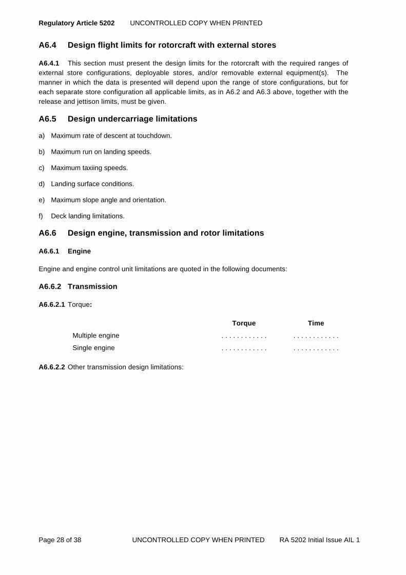
Regulatory Article 5202 UNCONTROLLED COPY WHEN PRINTED
Page 28 of 38 UNCONTROLLED COPY WHEN PRINTED RA 5202 Initial Issue AIL 1
A6.4 Design flight limits for rotorcraft with external stores
A6.4.1 This section must present the design limits for the rotorcraft with the required ranges of external store configurations, deployable stores, and/or removable external equipment(s). The manner in which the data is presented will depend upon the range of store configurations, but for each separate store configuration all applicable limits, as in A6.2 and A6.3 above, together with the release and jettison limits, must be given.
A6.5 Design undercarriage limitations
a) Maximum rate of descent at touchdown.
b) Maximum run on landing speeds.
c) Maximum taxiing speeds.
d) Landing surface conditions.
e) Maximum slope angle and orientation.
f) Deck landing limitations.
A6.6 Design engine, transmission and rotor limitations
A6.6.1 Engine
Engine and engine control unit limitations are quoted in the following documents:
A6.6.2 Transmission
A6.6.2.1 Torque:
Torque Time
Multiple engine . . . . . . . . . . . . . . . . . . . . . . . .
Single engine . . . . . . . . . . . . . . . . . . . . . . . . A6.6.2.2 Other transmission design limitations:

UNCONTROLLED COPY WHEN PRINTED Regulatory Article 5202
RA 5202 Initial Issue AIL1 UNCONTROLLED COPY WHEN PRINTED Page 29 of 38
A6.6.3 Rotor
A6.6.3.1 Rotor RPM:
ROTOR RPM
Nominal governed speed
Normal operational limits
Maximum transient limits
Power on Max
Min
Power off Max
Min
A6.6.3.2 Other rotor limitations. In addition to the tabular data on rotor RPM, limits due to stalling and compressibility versus altitude must be stated in graphic form.
A6.6.4 Landing limitations
A6.7 Miscellaneous system design limitations
A6.7.1 Appropriate design limitations must be given for systems such as the following:
a) Wheels, tyres, brakes.
b) Cabin and equipment conditioning.
c) Hydraulic systems.
d) Electrical systems.
e) Flying control and autostabilizer systems.
f) Autopilot and automatic flight control systems.
g) Head-up display.
h) Navigation and weapon aiming system.
i) Flight director(s).
j) Ice protection system.
k) Windscreen clearance and canopy.
l) Electronic countermeasures.
m) Onboard radar.
n) Emergency escape.
o) Electro-optic flying aids.

Regulatory Article 5202 UNCONTROLLED COPY WHEN PRINTED
Page 30 of 38 UNCONTROLLED COPY WHEN PRINTED RA 5202 Initial Issue AIL 1
A6.8 Design limitations in respect of miscellaneous phases of flight/roles
a) in-flight refuelling.
b) Night flying.
c) Shipborne operations (clause A6.5(f) and A6.6.4 above).
d) Use of special test equipment.
e) Role equipment, such as underslung loads, hoists, etc..
f) Use of armament systems.
g) Stores dropping
h) Night vision goggles.
i) Nuclear, biological, chemical protection equipment.

UNCONTROLLED COPY WHEN PRINTED Regulatory Article 5202
RA 5202 Initial Issue AIL1 UNCONTROLLED COPY WHEN PRINTED Page 31 of 38
ANNEX A7 TO SECTION 2 APPENDIX A MILITARY FLIGHT TEST PERMIT
FLYING LIMITATIONS - ROTORCRAFT
DEFINITIONS AND EXPLANATORY NOTES
A7.1 Definitions
A7.1.1 Flying Limitation. A performance or operation extreme to which the rotorcraft may be flown for test purposes, as recommended by the Design Organization.
A7.1.2 Basic Mass. The mass of the rotorcraft excluding the crew, but including gases, unconsumable fuel and fluids and all non expendable equipment which is common to all roles.
A7.1.3 Indicated Airspeed (IAS). IAS is defined as the instrument reading corrected for instrument error only. Pressure error correction curves for IAS are to be given in Annex A8 clause A8.11, stating clearly whether they are estimated or measured.
A7.1.4 Basic Rotorcraft. The term ‘basic rotorcraft’ is used to define the rotorcraft without external stores and/or removable external equipment.
A7.1.5 Rotorcraft Configuration. The term ‘rotorcraft configuration’ is used to refer to the shape that the rotorcraft adopts according to the various arrangements of movable structure such as undercarriage, doors and ramps, which may be selected by the crew or extended automatically, and external stores such as MAD. In this context, ‘clean’ is used to denote the basic rotorcraft configuration existing with all movable structure retracted and external stores removed.
A7.2 Explanatory Notes
A7.2.1 The scope of the Flying Limitations must not normally extend beyond the range of the tests conducted satisfactorily by the Contractor or conditions predicted by him to be satisfactory, from considerations of the safety of the rotorcraft. The PTL may give a more restrictive clearance, if he has reason to do so, e.g. he may restrict the maximum speed until certain phenomena have been fully investigated by the Contractor and/or MOD Establishment. Must values be given other than those obtained by flight test or, in the case of weights and CG positions, by direct weighing, comment is to be made.
A7.2.2 It is the DO’s responsibility to ensure that, in the event of dangerous flight conditions being encountered, within the issued Flying Limitations, the limits are amended to prohibit flight in that region.
A7.2.3 A detailed statement is required to indicate the basis on which the mass and centre of gravity data given in Annex A8 have been determined.
A7.2.4 The maximum overload mass for landing is defined as the maximum all-up-mass at which a landing without structural damage can be anticipated under ideal conditions - i.e. good visibility, ability to land into wind and on a smooth, level and hard landing area.

Regulatory Article 5202 UNCONTROLLED COPY WHEN PRINTED
Page 32 of 38 UNCONTROLLED COPY WHEN PRINTED RA 5202 Initial Issue AIL 1
A7.2.5 If any of the flight limitations of Annex A8 are due to the Contractor’s assessment of handling qualities, this is to be stated.
A7.2.6 In any particular flight test, the pilot must not deliberately exceed the limitations quoted. If any limitation is inadvertently exceeded the occurrence and its extent must be brought to the attention of the DO, and the PTL. Furthermore, in any particular flight test, the pilot must not exceed the published, or draft, Service limitations (or comparable limitations advised by the DO) except where it is necessary to do so to achieve the purposes of the flight test.
A7.2.7 The flight envelope and speed limitations can, if preferred, be defined graphically and attached to this form. In all cases the effect of mass and altitude and ambient temperature must be specified.
A7.2.8 If it is necessary to assume a position error to determine the IAS or EAS the best available data must be used. For diving speed limitations, however, the error is to be -5%, unless the prior agreement of the PTL, has been obtained to a different value.
A7.2.9 Low airspeeds will have to be estimated by the pilot. where possible, low airspeeds must be checked by ground measurement.
A7.2.10 The originator must ensure that the correct security marking is given to this Annex.
A7.2.11 The International System of units (SI) must be used for new projects, except for altitude in feet. However, where this form is used for existing rotorcraft for which Imperial units were used, the use of Imperial units must be continued. Any change from Imperial units to SI units must be clearly indicated.
A7.2.12 Each sheet of the statement of flying limitations is to show the standard of its issue.
UNCONTROLLED COPY WHEN PRINTED Regulatory Article 5202
RA 5202 Initial Issue AIL1 UNCONTROLLED COPY WHEN PRINTED Page 33 of 38
ANNEX A8 TO SECTION 2 APPENDIX A MILITARY FLIGHT TEST PERMIT
Flying Limitations - Rotorcraft
A8.1 Introduction
A8.1.1 This summary defines the data required in the Flying Limitations. The data presented must be as wide as possible, consistent with the stage of design/development reached. It must be self contained (i.e. must not cross refer to data contained in other MFTP, RTS etc. for the same type of rotorcraft) and must cover all such headings as are appropriate to the rotorcraft under test. The sections below must be regarded as examples only, but they must include all limitations applicable to airworthiness.
A8.1.2 Where stated, the data given in this Part are the Limitations to which the rotorcraft may be flown for test purposes, and under no circumstances are they deliberately to be exceeded (Annex A7, A7.2.6).
A8.2 Authorized Pilot Categories
A8.2.1 The Category of Pilot authorized to fly within the limitations stated in this Annex:
a) Test pilot*.
b) Pilot*.
As defined in FLY 2000.
* delete as appropriate
A8.3 Source of flight limitations
The source of the flying limitations are:
a) *Derived from flight and operating manuals of the Certificate of Airworthiness (date . . . . . . Ref . . . . , copies of which accompany this form).
b) *Derived from the attached Civil Design Certificate for Flight Trials (under Air Navigation Order B Conditions).
c) *Derived from other approved certification (ref . . . . . . Date . . . . . . . .).
d) *Derived from Release to Service (ref . . . . . . date . . . . . . . .)
* delete as appropriate
Regulatory Article 5202 UNCONTROLLED COPY WHEN PRINTED
Page 34 of 38 UNCONTROLLED COPY WHEN PRINTED RA 5202 Initial Issue AIL 1
A8.4 Mass and Centre of Gravity
A8.4.1 Maximum all-up-mass kg(lb)
a) Normal take-off.
b) Normal landing.
c) Overload take-off (gentle manoeuvre).
d) Overload landing (Annex A7, clause A7.2.4).
A8.4.2 The rotorcraft must always be loaded so that the perpendicular projection of the CG on the horizontal datum line, and the position of the CG above or below the horizontal datum line fall within the limits defined below when the undercarriage is DOWN and the rotor blades evenly spaced in plan view and resting against their droop stops:
a) Axis of reference for the horizontal CG.
b) Horizontal datum line.
c) Horizontal and vertical cg positions at appropriate masses.
d) Lateral cg limits to port and starboard of centre of line of rotorcraft.
A8.4.3 Other special limitations.
A8.5 Flight limits for basic rotorcraft (without external stores)
A8.5.1 Flight envelope
The flight envelope for the ‘clean’ rotorcraft must be presented in tabular and graphic form in terms of the variation of limits in airspeed with altitude.
A8.5.2 Maximum speeds
Maximum speeds must be tabulated for configurations or conditions, such as the following:
a) Level flight.
b) Dives.
c) Undercarriage down.
d) Sideways flight.
e) Rearward flight.
f) Autorotation (maximum and minimum airspeed).

UNCONTROLLED COPY WHEN PRINTED Regulatory Article 5202
RA 5202 Initial Issue AIL1 UNCONTROLLED COPY WHEN PRINTED Page 35 of 38
A8.5.3 Manoeuvre limitations
These must be defined in a convenient form (preferably tabular and graphic) for the following conditions of the clean rotorcraft:
a) Sustained and transient limitations for symmetric and asymmetric manoeuvres in terms of normal acceleration and any critical parameters such as rotor shaft bending.
b) Critical design features, e.g. Bank and sideslip limits.
c) Collective pitch angle applications.
A8.5.4 Atmospheric Limitations
A8.5.4.1 Altitude (at 1000 ft increments).
A8.5.4.2 Ambient temperature.
A8.5.4.3 Maximum windspeed:
a) Engine start.
b) Rotor start
c) Take off
d) Landing
e) Wind direction
A8.5.4.4 Contamination (dust, smoke, etc.).
A8.5.4.4 Icing and snow.
A8.4.4.5 Turbulence.
A8.6 Flight limits for rotorcraft with external stores
A8.6.1 This section must present the flight limitations for the rotorcraft with the required range of external stores and/or all removable external equipment.
A8.6.2 The manner in which this data is presented will depend upon the range of stores configurations, but for each separate store configuration all applicable limits as in Clauses A8.4 and A8.5 above must be given, including release and jettison.
A8.7 Undercarriage limitations
a) Maximum rate of descent at touchdown.
b) Maximum run on landing speeds.
c) Maximum taxiing speeds.
d) Landing surface conditions.

Regulatory Article 5202 UNCONTROLLED COPY WHEN PRINTED
Page 36 of 38 UNCONTROLLED COPY WHEN PRINTED RA 5202 Initial Issue AIL 1
e) Maximum slope angle and orientation.
f) Deck landing limitations.
A8.8 Engines, transmission and rotor limitations
A8.8.1 Engines
A8.8.1.1 The following engine limitations must not be exceeded:
Rating Time Limit for
Application
Max gas generator
RPM
Max power turbine RPM
Max power turbine inlet
Temp °C
Max*** Torque
** Max contingency ** Inter-contingency Take-off (or Max 5 minutes)
Max continuous
Autorotation
Flight idling
Ground idling
**Transient Accessories only
Starting
** After failure on one engine. *** These are engine limits. for transmission limits see clause A8.8.2. (Note that engine limits may exceed transmission limits). A8.8.1.2 The above engine limitations are quoted in:
Date Issue
*Engine Designer’s Technical Certificate . . . . . . . . . . . . . . . . . . . . . . . .
*Engine Designer’s Flight Clearance Note . . . . . . . . . . . . . . . . . . . . . . . .
*Air publication . . . . . . . . . . . . . . . . . . . . . . . . * Delete as applicable
A8.8.1.3 Other engines and engine control unit limitations.
A8.8.1.4 Types of fuel.
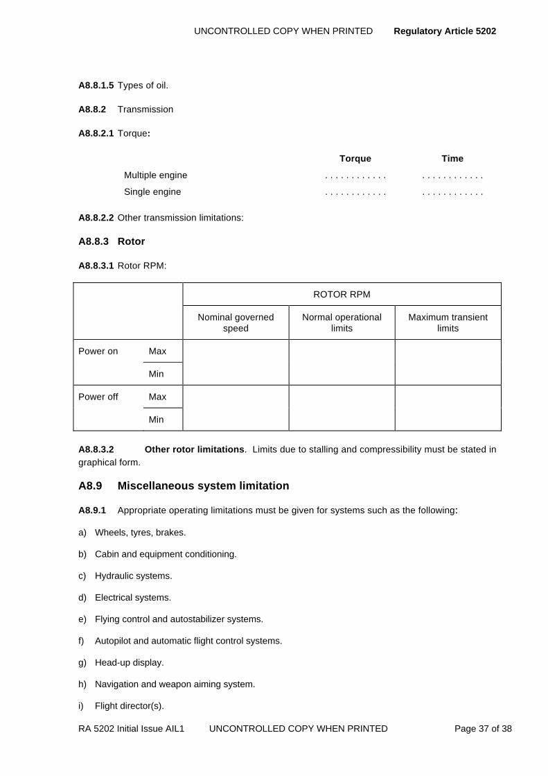
UNCONTROLLED COPY WHEN PRINTED Regulatory Article 5202
RA 5202 Initial Issue AIL1 UNCONTROLLED COPY WHEN PRINTED Page 37 of 38
A8.8.1.5 Types of oil.
A8.8.2 Transmission
A8.8.2.1 Torque:
Torque Time
Multiple engine . . . . . . . . . . . . . . . . . . . . . . . .
Single engine . . . . . . . . . . . . . . . . . . . . . . . . A8.8.2.2 Other transmission limitations:
A8.8.3 Rotor
A8.8.3.1 Rotor RPM:
ROTOR RPM
Nominal governed speed
Normal operational limits
Maximum transient limits
Power on Max
Min
Power off Max
Min
A8.8.3.2 Other rotor limitations. Limits due to stalling and compressibility must be stated in graphical form.
A8.9 Miscellaneous system limitation
A8.9.1 Appropriate operating limitations must be given for systems such as the following:
a) Wheels, tyres, brakes.
b) Cabin and equipment conditioning.
c) Hydraulic systems.
d) Electrical systems.
e) Flying control and autostabilizer systems.
f) Autopilot and automatic flight control systems.
g) Head-up display.
h) Navigation and weapon aiming system.
i) Flight director(s).

Regulatory Article 5202 UNCONTROLLED COPY WHEN PRINTED
Page 38 of 38 UNCONTROLLED COPY WHEN PRINTED RA 5202 Initial Issue AIL 1
j) Ice protection system.
k) Windscreen clearance and canopy.
l) Electronic countermeasures.
m) Onboard radar.
n) Emergency escape.
o) Electro-optic flying aids.
A8.10 Limitations in respect of miscellaneous phases of flight/roles
A8.10.1 Appropriate limitations must be given for items or conditions such as the following:
a) In-flight refuelling.
b) Night and instrument flying.
c) Shipborne operations.
d) Use of special test equipment.
e) Role equipment, such as underslung loads, hoists, etc..
f) Use of armament systems.
g) Stores dropping
h) Night vision goggles.
i) Nuclear, biological, chemical protection equipment.
A8.11 Relevant publications
A8.11.1 All documents required for the maintenance and operation of the rotorcraft (e.g. Vol 1 Aircrew Manual, Operating Data Manual) must be referenced. In particular, the contractor must supply details of recommended piloting techniques and associated reference/control speeds for all relevant phases of flight. and estimated/measured data on the performance to be expected.

UNCONTROLLED COPY WHEN PRINTED Regulatory Article 5203
RA 5203 Initial Issue UNCONTROLLED COPY WHEN PRINTED Page 1 of 6
RA 5203 – Requirement Specifications
Rationale When the MOD invites tenders for the design and development of materiel, the requirements are stated in the specification defining the materiel in terms of functional, or performance, or physical characteristics, or a combination of two or more of these. When requirements can be met by equipment which is already available, or is expected to become available within a suitable time-scale, a Cardinal Point Specification (CPS) may be issued. A CPS defines the minimum acceptable requirements in terms of performance, engineering standards, interface requirements etc. and the parameters in which improvement beyond the minimum should be considered.
Contents 5203(1): Environmental Effect
5203(2): Contract Specifications
5203(3): Sub-Contract Specifications
5203(4): Explosives, Electro-Explosive Devices & Lasers
Regulation
5203(1)
Environmental Effect 5203(1) All procurement decisions shall take account of the
environmental implications of the available options.
Acceptable Means of Compliance
5203(1)
1. Specifications should not require either directly or by implication the use of substances which could create an adverse environmental effect during the manufacture, use, or disposal of the materiel. Specifications should not require the use of substances controlled by the Montreal Protocol and associated European Community regulations.
2. Contractors should advise the PTL of any unavoidable adverse environmental effects.
Guidance Material
5203(1)
Nil
Regulation
5203(2)
5203(3)
Contract Specifications 5203(2) Specifications prepared by contractors which are intended to
form the basis of a contract shall be certified by the contractor before submission to the PTL.
Sub-Contract Specifications
5203(3) Specifications prepared by a contractor in support of a contract, e.g. for use with sub-contractors, shall pass on all appropriate MOD requirements and shall be certified by the contractor.

Regulatory Article 5203 UNCONTROLLED COPY WHEN PRINTED
Page 2 of 6 UNCONTROLLED COPY WHEN PRINTED RA 5203 Initial Issue
Acceptable Means of Compliance
5203(2)
5203(3)
3. The format and content of specifications should follow the guidance contained in NATO Allied Engineering Documentation Publication AEDP-1 Annex C and the requirements of this RA.
4. Subsidiary specifications or standards additional to those stipulated in the contract specification should be selected in the following order of preference:
a. European Standards (British Standards implementing European Standards).
b. ISO Standards (British Standards implementing International Standards).
c. British Standards.
d. Defence Standards.
5. Specifications form a part of the design records for the materiel and should be subject to the configuration control requirements of the agreed Configuration Management Plan (CMP) prepared in accordance with Def Stan 05-57.
6. Design Requirements. Specifications for Service aircraft (including unmanned air vehicles), aircraft gas turbine engines, and guided weapon systems should state that the materiel should be designed to the requirements respectively of Def Stan 00-970 (appropriate part) or Def Stan 07-85, amended up to and including a specified standard, with any exceptions so stated in the specification.
7. Aircraft Specifications. For complete aircraft and for major modifications the specifications should comply also with the requirements of Appendix A.
Guidance Material
5203(2)
5203(3)
9. Potential contractors will be invited to respond to an Invitation To Tender (ITT) with a detailed specification which can be used to form the basis of a contract.
10. During the design and development of materiel the contractor will generate any specifications necessary for the control of sub-contracted items of materiel. The contractor must, in the absence of suitable specifications for materials and manufacturing processes, produce such specifications.
11. The PTL reserves the right to comment on such specifications. Where this is considered unnecessary, the PTL reserves the right of access for information purposes.
12. Procedures for the preparation of specifications for materials or processes for parts the failure of which could affect airworthiness are defined in Appendix B.
Regulation
5203(4)
Explosives, Electro-Explosive Devices & Lasers 5203(4) Specifications relating to explosives, Electro-Explosive
Devices (EEDs), lasers and associated components, circuitry and wiring shall be approved prior to issue by the safety officer at the contractor where the specification is prepared.

UNCONTROLLED COPY WHEN PRINTED Regulatory Article 5203
RA 5203 Initial Issue UNCONTROLLED COPY WHEN PRINTED Page 3 of 6
Acceptable Means of Compliance
5203(4)
13. Each specification should be endorsed ‘Safety - any proposed alteration to this specification should be referred to the safety officer for approval’.
14. A specification covering an explosive component or components should include a requirement for proofing during qualification and production. Def Stan 05-61 Part 14 refers.
Guidance Material
5203(4)
15. Procedures for the preparation of specifications for materials or processes for parts the failure of which could affect airworthiness are defined in Appendix B

Regulatory Article 5203 UNCONTROLLED COPY WHEN PRINTED
Page 4 of 6 UNCONTROLLED COPY WHEN PRINTED RA 5203 Initial Issue
APPENDIX A INSTRUCTIONS FOR THE PREPARATION OF AIRCRAFT SPECIFICATIONS BY
CONTRACTORS
A.1 Specification identification
A.1.1 Aircraft specification numbers will be notified to the contractor by the PTL.
A.1.2 The identification system recognises three distinct types of specification:
A.1.3 The T specification (e.g. FGA 250T) for use by MOD in connection with invitations to tender, or requests for proposal.
A.1.4 The D specification (e.g. FGA 250D) for project definition, or development.
A.1.5 The P specification (e.g. FGA 250P) for production.
A.1.6 It may be appropriate to produce a dual specification, e.g. FGA 250 D&P where the specification defines the requirements for the development and production of a new version of an existing aircraft type already in military use, or for a military version of a civil aircraft.
A.2 Design requirements
A.2.1 Service aircraft. Specifications for Service aircraft must state that the aircraft must be designed to the requirements of the appropriate part or parts of Def Stan 00-970, amended up to and including a specified standard, with any exceptions stated in the specification or agreed equivalent.
A.2.2 Military derivatives of civil aircraft. Specifications for military derivatives of civil aircraft must state that the basic design will be in accordance with the appropriate EASA Certification Standard or other equivalent and agreed requirement. Any alterations to the basic design necessary to meet the military role of the aircraft must be in accordance with Def Stan 00-970 amended up to and including a specified standard with any exceptions stated in the specification, or agreed equivalent. Where difficulties arise owing to differences between the design requirement and the Certification Standard, they must be resolved on the basis of the safety case demonstrating that no additional risk is incurred by not designing to Def Stan 00-970 requirements.
A.3 Appendices to specifications
A.3.1 Development specifications. Development specifications must include the following appendices:
a) Appendix A a list of all equipment to be fitted indicating source of supply, fitment category, type etc. as described in RA 5214;
b) Appendix B a statement of the performance of the aircraft and its equipment for use principally during official flight testing, see RA 5217, carried out in connection with preparation of the Aircraft Release (MA Release), RA 5001 refers. The statement must make a clear distinction between performance parameters, which are guaranteed by the contractor, and those which are estimates provided as a basis for tests and evaluation.
UNCONTROLLED COPY WHEN PRINTED Regulatory Article 5203
RA 5203 Initial Issue UNCONTROLLED COPY WHEN PRINTED Page 5 of 6
A.3.2 Production specifications. Production specifications must include Appendix A as described at clause A.3.1 and;
a) Appendix C The Y-list; RA 5307 refers. The Y-lists are master lists of the modifications which are embodied in the equipment during production.

Regulatory Article 5203 UNCONTROLLED COPY WHEN PRINTED
Page 6 of 6 UNCONTROLLED COPY WHEN PRINTED RA 5203 Initial Issue
APPENDIX B CONTRACTORS’ MATERIAL AND PROCESS SPECIFICATIONS
B.1 Introduction
A contractor is responsible for ensuring that any material or process specified in the design of an item of materiel is suitable for the intended application and that there is an appropriate specification for the material or process. In the absence of suitable specifications for materials and manufacturing processes, the contractor must produce such specifications.
B.2 Requirements
B.2.1 In the case of parts the failure of which could affect airworthiness (see clause B.2.2) normally only materials or processes controlled by those series of specifications listed in the following documents must be used:
c) Aircraft and Unmanned Air Vehicles. Def Stan 00-970 Part 1 Section 4.1 and Part 7 Section 4 Leaflet. 400.
d) Engines. Def Stan 00-970 Part 11;
e) Guided Weapons, Torpedoes and Airborne Armament Stores. Def Stan 07-85.
B.2.2 Parts affecting airworthiness. The following categories of parts are considered as affecting airworthiness:
f) Aircraft and Unmanned Air Vehicles Grade A parts as defined in Def Stan 00-970 Part 1 Section 4.1 and Part 7 Section 4 Leaflet 400:
g) Engines. Critical parts as defined in Def Stan 00-970 Part 11;
h) Guided weapons, Torpedoes and Airborne Armament Stores. Grade A parts as defined in Def Stan 07-85;
i) Petroleum, Oil and Lubricant (POL). POL used with or in aircraft, unmanned air vehicles, engines, guided weapons, torpedoes and airborne armament stores.
B.2.3 If no suitable specification is available from the series of specifications listed in the documents at clause B.2.1, the contractor must prepare and maintain an appropriate material or process specification (contractor materiel or process specification). If amendment of an available specification would make it suitable for the intended use, the relevant contractor materiel or process specification must quote the basic specification and detail the changes made. If a suitable specification later becomes available in the series of specifications listed in the documents at clause B.2.1, the contractor must consider cancellation or amendment of the contractor materiel or process specification as appropriate. The contractor must also review contractor materiel and process specifications at least every 5 years with a view to confirming, revising or cancelling the specifications as appropriate. Design records must be annotated to show last and next review dates.

UNCONTROLLED COPY WHEN PRINTED Regulatory Article 5204
RA 5204 Initial Issue UNCONTROLLED COPY WHEN PRINTED Page 1 of 4
RA 5204 - Information for Installation of Aircraft or Remotely Piloted Air Systems Equipment
Rationale In order to ensure satisfactory interfaces between aircraft or Remotely Piloted Air Systems (RPAS) and equipment it is necessary for equipment contractors to provide installation information. This RA details the information to be provided and defines the responsibility of aircraft/RPAS contractors for interface requirements.
Contents 5204(1): Interface Responsibilities
Regulation
5204(1)
Interface Responsibilities 5204(1) The aircraft/RPAS contractor shall be responsible for
ensuring that the installation, functional and environmental requirements for all interfaces, including Government Furnished Assets (GFA), are agreed between the design contractors concerned and that adequate documentation defining the interfaces is prepared.
Acceptable Means of Compliance
5204(1)
1. Except where the requirement is modified or waived by the contract, the installation/interface information should be provided for radio equipment in a Radio Installation Memorandum (RIM) and for other items of equipment in a document generally known as Aircraft Equipment Installation Information (AEII). The content and layout for the information that should be provided in a RIM or AEII is detailed in Appendix A.
2. Where equipment is supplied under a contract from the aircraft/RPAS contractor, the aircraft/UAV contractor should be responsible for defining the format and depth of installation/interface information required.
3. When the interface features have been agreed they should not be changed without reference to, and agreement by, all the design contractors concerned.
4. A RIM should be identified by a serial number notified by the PTL. An AEII should be identified by a drawing number and should be included in the Configuration Status Record (CSR) for the equipment.
Guidance Material
5204(1)
5. Additional information may be required for complex equipment such as aircraft engines. The interface requirements for engines are detailed in Def Stan 00-970 Part 11 and will be included, where appropriate, in the engine specification.
6. The RIM or AEII must be compiled as early as possible in the installation design programme even if at that stage it is only provisional. As development of the equipment proceeds, the document must be progressively updated until the completion of the design.
7. The RIM or AEII provides information for use by the aircraft/RPAS contractor in the design of equipment installations.
8. The installation, functional and environmental interfaces definitions documentation may be formally known as the Interface Control Document (ICD).
9. Each issue of RIM/AEII must carry an issue number and date. Incomplete or

Regulatory Article 5204 UNCONTROLLED COPY WHEN PRINTED
Page 2 of 4 UNCONTROLLED COPY WHEN PRINTED RA 5204 Initial Issue
Guidance Material
5204(1)
provisional issues will be letter Issue A, Issue B, etc. When the design is complete the RIM/AEII will be published as Issue 1 and any subsequent issues as Issue 2, Issue 3 etc.
10. The equipment contractor must distribute copies of the interface documentation (RIM, AEII, Interface Control Documents etc) in accordance with the standard distribution for the type record or as advised by the PTL, which must include the aircraft/RPAS contractor responsible for integration.
11. The equipment contractor must maintain the RIM/AEII until this responsibility is formally transferred, for example, to a PDS contractor.
12. Irrespective of any variation of the requirement that may be stated in the contract, the equipment contractor must provide details of the mass of the equipment. This information must be supplied to the PTL, on a CA(PE) Form 893 ‘Aircraft Equipment Mass’ (see RA 5205).
13. Where mock-ups and working rigs are used to verify installation interfaces the requirements of RA 5211 for aircraft and the RA 5600 series for engines and jet pipes are to be followed.
14. An aircraft/RPAS contractor who procures interface information from an equipment sub-contractor must ensure that the information is readily identifiable and recorded in the CSR. This is to ensure that the information will be available to any other contractor who may be required to assume Post Design Services (PDS) responsibilities for the equipment.

UNCONTROLLED COPY WHEN PRINTED Regulatory Article 5204
RA 5204 Initial Issue UNCONTROLLED COPY WHEN PRINTED Page 3 of 4
APPENDIX A
CONTENT AND LAYOUT OF A RIM/AEII
A.1 Introduction
A RIM/AEII may be prepared in any convenient form provided it is presented under the main and sub-headings set out in clause A.2 and contains at least the information listed therein. The headings listed must be supplemented by any further information that may contribute to the design of a satisfactory installation. Reference must be made, where appropriate, to compliance with the relevant requirements of Defence Standards, British Standards, US Military Specifications etc.
A.2 Content
Information in a RIM/AEII must include the following:
A.2.1 Part 1 ‘Technical Summary’
a) Description. Brief narrative description of purpose and function of equipment and main facilities provided by it.
b) Technical Data. Main parameters in tabular form.
c) Configuration. List of main units and assemblies constituting the equipment (with part numbers and NATO stock numbers where available).
d) Associated Equipment. List of associated equipment and variants.
e) Documentation. List of related documents.
A.2.2 Part 2 ‘Installation Data’
a) Dimensions. Maximum overall envelope. sizes, shapes and masses and range of cg position of all separate units and assemblies including aerials.
b) Imposed Loads. Forces and moments exerted on the aircraft including dynamic effects due to moving parts.
c) Location. Attitude, limitations, method of attachment and clearances required for fitting and for access for maintenance; position of controls and indicators, aerial siting and compass safe distance.
d) Environment. Environmental limits; requirements for heating, cooling or other conditioning; sealing, bonding and anti-corrosion measures; required electrical properties for covers or radomes.
e) Interconnections. Cable assemblies; recommended cables and connectors; limits on current capacity, loss, impedance; voltage standing wave ratio and frequency response for cables, feeders and wave guides; screening and bonding.
f) Interfaces. Input and output levels and impedance at interfaces with associated equipment and instruments; tolerances, permissible loadings and dynamic ranges; grounding arrangements; Data bus requirements.

Regulatory Article 5204 UNCONTROLLED COPY WHEN PRINTED
Page 4 of 4 UNCONTROLLED COPY WHEN PRINTED RA 5204 Initial Issue
g) Power Supplies. Hydraulic, pneumatic and electrical power supplies required; for electrical power: voltage, current, impedance and frequency of power supply lines, with tolerances; surge starting loads, imported and exported interference limits.
h) Electromagnetic Compatibility (EMC). Susceptibility to radiated and conducted signals; frequency and level of generated radiations; EMC categorisation of interconnections.
i) Hazards. Mechanical, electrical, thermal and chemical hazards, entailing potential injury to personnel and damage to equipment.
A.2.3 Part 3 ‘Testing’
a) Pre-installation Testing. Bench and rig tests on line replaceable units (LRUs); acceptance limits.
b) Post-installation Testing. Tests on LRUs after installation in aircraft; functional system tests.
c) Test Equipment. Recommended test equipment; special test facilities and supporting services.
A.2.4 Part 4 ‘Drawings’
Copies of drawings referred to in the text, including layouts of separate units and assemblies, mounting details, functional block diagrams and interface diagrams showing test points and signal levels.

UNCONTROLLED COPY WHEN PRINTED Regulatory Article 5205
RA 5205 Initial Issue UNCONTROLLED COPY WHEN PRINTED Page 1 of 4
RA 5205 - Reporting of Mass for Aircraft Equipment
Rationale This RA sets out the procedure for reporting the mass of aircraft equipment, excluding engines and jet pipes, to be developed under direct (MOD) contract.
Contents 5205(1): Reporting of Mass for Aircraft Equipment
Regulation
5205(1)
Reporting of Mass for Aircraft Equipment 5205(1) The contractor shall report the mass of aircraft equipment
using the Aircraft Equipment Mass form, an example of which appears at Appendix A.
Acceptable Means of Compliance
5205(1)
1. Reports should be supplied:
a. within one month of the date of the initial development contract.
b. subsequently at 3 monthly intervals until the Certificate of Design has been issued and accepted.
2. The distribution of the completed Form should be through the PTL as follows:
a. PTL 4 copies.
b. Aircraft Contractor 1 copy.
Guidance Material
5205(1)
3. The requirements for reporting of mass for engines and jet pipes are detailed RA 5607.
4. The Form at Appendix A must be reproduced locally.
5. A computer printout following the same format may be used as an alternative.
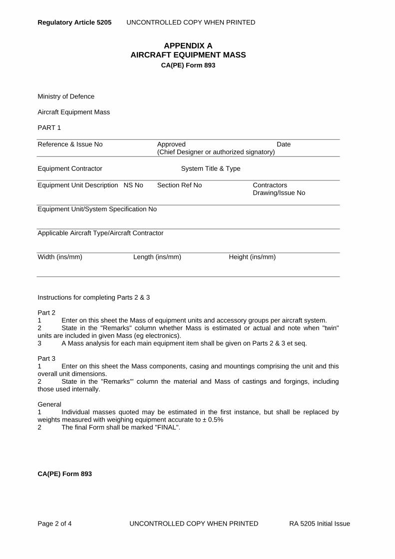
Regulatory Article 5205 UNCONTROLLED COPY WHEN PRINTED
Page 2 of 4 UNCONTROLLED COPY WHEN PRINTED RA 5205 Initial Issue
APPENDIX A AIRCRAFT EQUIPMENT MASS
CA(PE) Form 893
Ministry of Defence
Aircraft Equipment Mass
PART 1
Reference & Issue No Approved Date (Chief Designer or authorized signatory)
Equipment Contractor System Title & Type
Equipment Unit Description NS No Section Ref No Contractors Drawing/Issue No Equipment Unit/System Specification No Applicable Aircraft Type/Aircraft Contractor Width (ins/mm) Length (ins/mm) Height (ins/mm) Instructions for completing Parts 2 & 3 Part 2 1 Enter on this sheet the Mass of equipment units and accessory groups per aircraft system. 2 State in the "Remarks" column whether Mass is estimated or actual and note when "twin" units are included in given Mass (eg electronics). 3 A Mass analysis for each main equipment item shall be given on Parts 2 & 3 et seq. Part 3 1 Enter on this sheet the Mass components, casing and mountings comprising the unit and this overall unit dimensions. 2 State in the "Remarks"' column the material and Mass of castings and forgings, including those used internally. General 1 Individual masses quoted may be estimated in the first instance, but shall be replaced by weights measured with weighing equipment accurate to ± 0.5% 2 The final Form shall be marked "FINAL".
CA(PE) Form 893
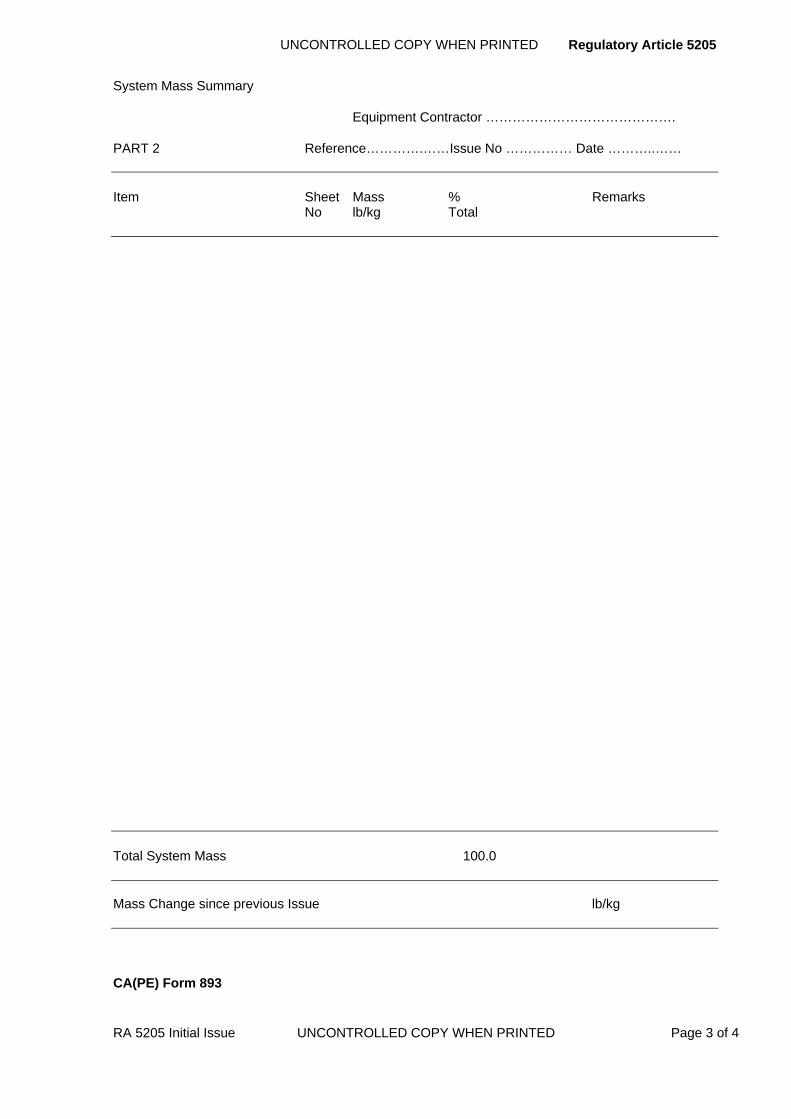
UNCONTROLLED COPY WHEN PRINTED Regulatory Article 5205
RA 5205 Initial Issue UNCONTROLLED COPY WHEN PRINTED Page 3 of 4
System Mass Summary
Equipment Contractor …………………………………….
PART 2 Reference………….……Issue No …………… Date ………..……
Item Sheet Mass % Remarks No lb/kg Total
Total System Mass 100.0 Mass Change since previous Issue lb/kg
CA(PE) Form 893
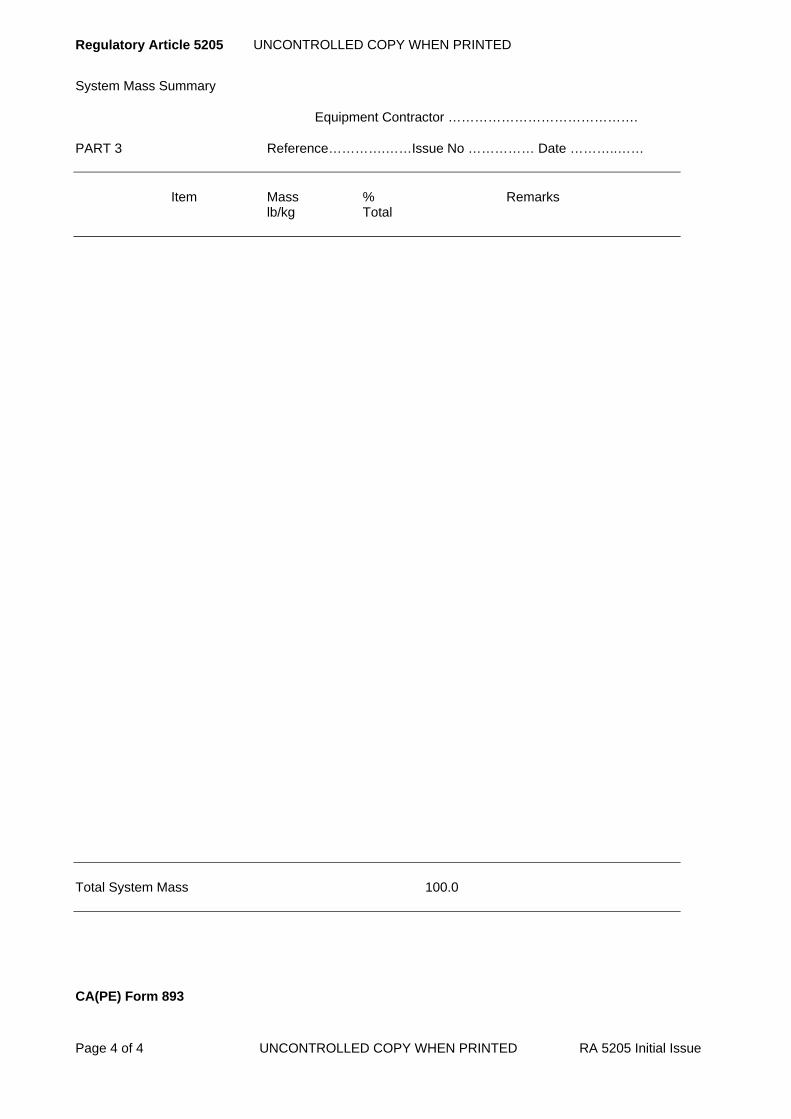
Regulatory Article 5205 UNCONTROLLED COPY WHEN PRINTED
Page 4 of 4 UNCONTROLLED COPY WHEN PRINTED RA 5205 Initial Issue
System Mass Summary
Equipment Contractor …………………………………….
PART 3 Reference………….……Issue No …………… Date ………..……
Item Mass % Remarks lb/kg Total
Total System Mass 100.0 CA(PE) Form 893

UNCONTROLLED COPY WHEN PRINTED Regulatory Article 5206
RA 5206 Initial Issue UNCONTROLLED COPY WHEN PRINTED Page 1 of 2
RA 5206 - Sampling Procedure for In-Service Materiel
Rationale The PT responsible for an item of materiel may, during the in-Service life of the materiel, require that the materiel be subjected to a sampling programme with a view to assessing whether the maintenance frequency should be altered or the reconditioning life changed. This RA describes the procedure to be followed by a contractor when tasked by the PTL, to carry out activities in support of a sampling programme.
Contents 5206(1): Sampling Procedure
Regulation
5206(1)
Sampling Procedure 5206(1) The PTL shall arrange the necessary contract cover, with the
relevant contractor to devise a test programme for the proposed sampling programme.
Acceptable Means of Compliance
5206(1)
1. Whenever materiel included in a sampling programme is returned to the contractor, normally by fault report action, the contractor should notify the PTL of the date, time and location scheduled for the tests and strip examination.
2. The contractor should test the item in accordance with the agreed programme and submit a report to the PTL, covering the following points:
a. The deterioration in performance and/or the degree of wear which has occurred and which would be rectified during reconditioning but which would not, to the extent found, cause a failure.
b. The contractor’s recommended future service life for this type of item, whether further sampling is required, contractual arrangements.
c. Those features of design which limit life extension and whether modification action is feasible and economic.
Guidance Material
5206(1)
3. The test programme may involve repetition of previous tests and strip examination of selected items after a predetermined period of In-Service use. The test programme will be agreed with the PTL.
4. Appropriate contractual arrangements will be made compatible to the reason for the sampling programme being carried out. For example in the case of a sampling programme arranged in connection with materiel which does not meet specification reliability requirements, it may be appropriate for the relevant contractor to bear the costs of additional work arising from the test programme, e.g. rig testing, strip examination and preparation of test reports.
5. Considerations similar to those at the paragraph above will apply to the cost of repair work (where necessary), re-assembly and normal testing of materiel on conclusion of strip examination, reporting etc.

Regulatory Article UNCONTROLLED COPY WHEN PRINTED
Page 2 of 2 UNCONTROLLED COPY WHEN PRINTED RA Initial Issue
Intentionally Blank for Print Pagination
UNCONTROLLED COPY WHEN PRINTED Regulatory Article 5207
RA 5207 Initial Issue UNCONTROLLED COPY WHEN PRINTED Page 1 of 2
RA 5207 - Identification Under the NATO Codification System
Rationale This section of the DefStan contains details of extant publications. Duplicated information removed. This RA is raised for completeness and to show that this section has not been missed, but it is a Nul RA
Contents Nil
Regulation
5207(1)
Nil 5207(1) Section orphaned as refers to extant publications. Duplication
of information removed.
Acceptable Means of Compliance
5207(1)
Nil
Guidance Material
5207(1)
Nil

Regulatory Article UNCONTROLLED COPY WHEN PRINTED
Page 2 of 2 UNCONTROLLED COPY WHEN PRINTED RA Initial Issue
Intentionally Blank for Print Pagination
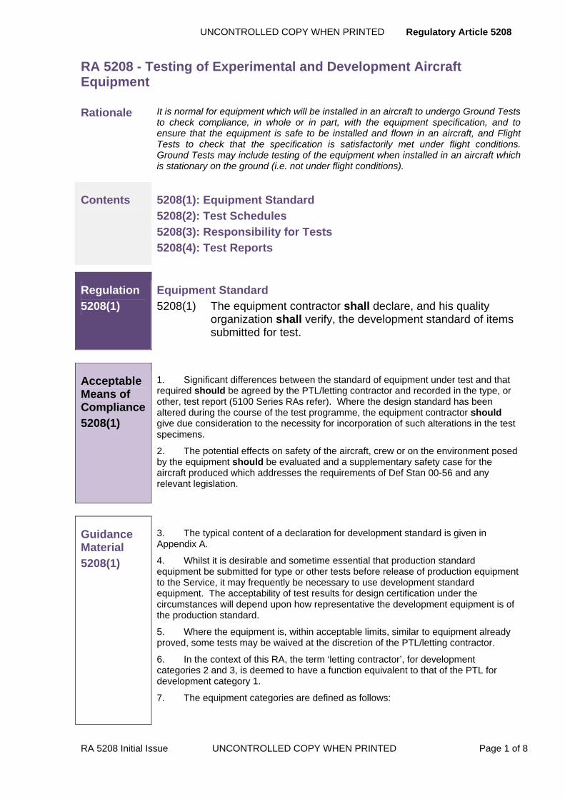
UNCONTROLLED COPY WHEN PRINTED Regulatory Article 5208
RA 5208 Initial Issue UNCONTROLLED COPY WHEN PRINTED Page 1 of 8
RA 5208 - Testing of Experimental and Development Aircraft Equipment
Rationale It is normal for equipment which will be installed in an aircraft to undergo Ground Tests to check compliance, in whole or in part, with the equipment specification, and to ensure that the equipment is safe to be installed and flown in an aircraft, and Flight Tests to check that the specification is satisfactorily met under flight conditions. Ground Tests may include testing of the equipment when installed in an aircraft which is stationary on the ground (i.e. not under flight conditions).
Contents 5208(1): Equipment Standard
5208(2): Test Schedules
5208(3): Responsibility for Tests
5208(4): Test Reports
Regulation
5208(1)
Equipment Standard 5208(1) The equipment contractor shall declare, and his quality
organization shall verify, the development standard of items submitted for test.
Acceptable Means of Compliance
5208(1)
1. Significant differences between the standard of equipment under test and that required should be agreed by the PTL/letting contractor and recorded in the type, or other, test report (5100 Series RAs refer). Where the design standard has been altered during the course of the test programme, the equipment contractor should give due consideration to the necessity for incorporation of such alterations in the test specimens.
2. The potential effects on safety of the aircraft, crew or on the environment posed by the equipment should be evaluated and a supplementary safety case for the aircraft produced which addresses the requirements of Def Stan 00-56 and any relevant legislation.
Guidance Material
5208(1)
3. The typical content of a declaration for development standard is given in Appendix A.
4. Whilst it is desirable and sometime essential that production standard equipment be submitted for type or other tests before release of production equipment to the Service, it may frequently be necessary to use development standard equipment. The acceptability of test results for design certification under the circumstances will depend upon how representative the development equipment is of the production standard.
5. Where the equipment is, within acceptable limits, similar to equipment already proved, some tests may be waived at the discretion of the PTL/letting contractor.
6. In the context of this RA, the term ‘letting contractor’, for development categories 2 and 3, is deemed to have a function equivalent to that of the PTL for development category 1.
7. The equipment categories are defined as follows:
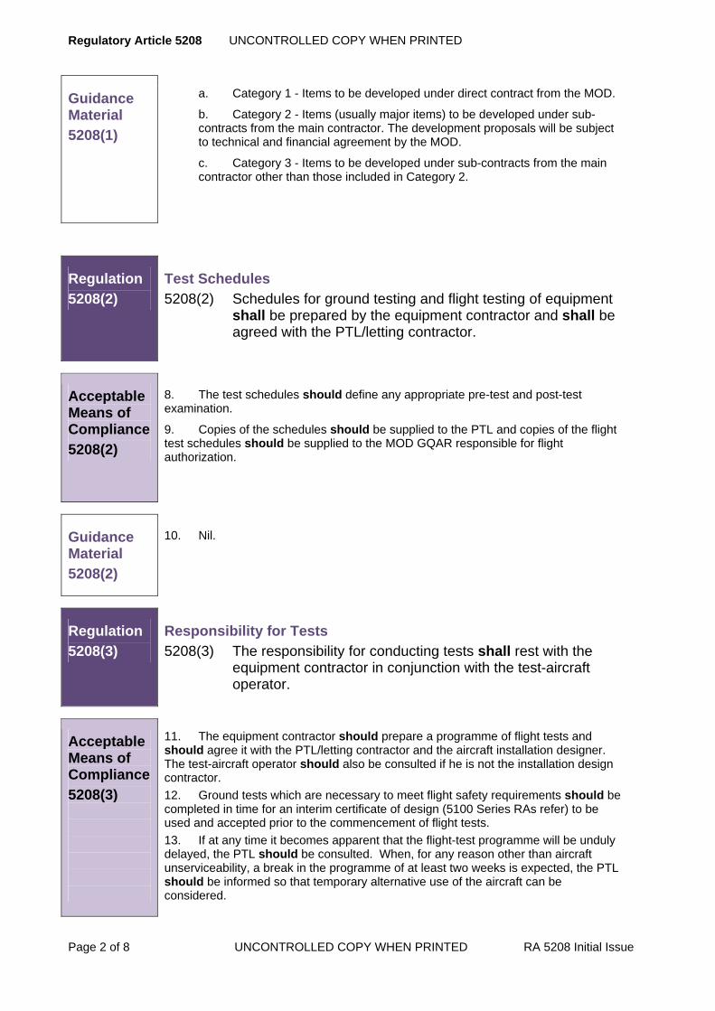
Regulatory Article 5208 UNCONTROLLED COPY WHEN PRINTED
Page 2 of 8 UNCONTROLLED COPY WHEN PRINTED RA 5208 Initial Issue
Guidance Material
5208(1)
a. Category 1 - Items to be developed under direct contract from the MOD.
b. Category 2 - Items (usually major items) to be developed under sub-contracts from the main contractor. The development proposals will be subject to technical and financial agreement by the MOD.
c. Category 3 - Items to be developed under sub-contracts from the main contractor other than those included in Category 2.
Regulation
5208(2)
Test Schedules 5208(2) Schedules for ground testing and flight testing of equipment
shall be prepared by the equipment contractor and shall be agreed with the PTL/letting contractor.
Acceptable Means of Compliance
5208(2)
8. The test schedules should define any appropriate pre-test and post-test examination.
9. Copies of the schedules should be supplied to the PTL and copies of the flight test schedules should be supplied to the MOD GQAR responsible for flight authorization.
Guidance Material
5208(2)
10. Nil.
Regulation
5208(3)
Responsibility for Tests 5208(3) The responsibility for conducting tests shall rest with the
equipment contractor in conjunction with the test-aircraft operator.
Acceptable Means of Compliance
5208(3)
11. The equipment contractor should prepare a programme of flight tests and should agree it with the PTL/letting contractor and the aircraft installation designer. The test-aircraft operator should also be consulted if he is not the installation design contractor. 12. Ground tests which are necessary to meet flight safety requirements should be completed in time for an interim certificate of design (5100 Series RAs refer) to be used and accepted prior to the commencement of flight tests. 13. If at any time it becomes apparent that the flight-test programme will be unduly delayed, the PTL should be consulted. When, for any reason other than aircraft unserviceability, a break in the programme of at least two weeks is expected, the PTL should be informed so that temporary alternative use of the aircraft can be considered.

UNCONTROLLED COPY WHEN PRINTED Regulatory Article 5208
RA 5208 Initial Issue UNCONTROLLED COPY WHEN PRINTED Page 3 of 8
Acceptable Means of Compliance
5208(3)
14. The equipment contractor should provide periodic progress reports as required.
15. An equipment contractor intending to conduct tests should give sufficient notice to the PTL or letting contractor as appropriate to allow time for making the necessary arrangements, including the provision of facilities for the tests to be witnessed.
16. The equipment contractor should consult the PTL/letting contractor to establish as early as possible the necessity for flight tests, so as to ensure availability of a test aircraft. If the equipment contractor does not operate a suitable aircraft he should request the allocation of an aircraft as soon as a firm date for the commencement of tests can be given.
17. The conduct and conditions of all tests and physical examinations should be to the satisfaction of the PTL/letting contractor.
18. The PTL/letting contractor should ensure that all tests representing operations performed by Service personnel are made as far as possible under representative Service conditions using Service equipment and techniques.
19. Where the malfunctioning of equipment may affect the safety of aircraft or crew, the possible effects should be assessed by the installation design contractor in consultation as necessary with the PTL/letting contractor, the test-aircraft operator and the aircraft designer. If the safety devices are considered to be inadequate the equipment contractor should make agreed improvements before test flying is permitted. The equipment installation contractor should include in the Military Flight Test Permit (MFTP)(RA5202) a statement that the effects of malfunctioning have been investigated and that the embodied safety features are considered adequate to limit the hazard to an acceptable level for experimental flying.
20. Before flight tests are permitted on equipment under initial development, certain ground tests should be performed and an interim certificate of design should be issued (RA5201 refers). Equipment should not therefore be considered for flight testing until the state of development justifies the issue of an interim certificate. The necessary pre-flight tests should be agreed between the equipment contractor or PTL/letting contractor and the aircraft installation design contractor. The test aircraft operator should also be consulted if he is not the installation design contractor.
21. For equipment tests in which the aircraft is used only as a test vehicle the equipment contractor should assess the instrumentation requirements, obtain and calibrate the instruments and arrange for their installation in the aircraft.
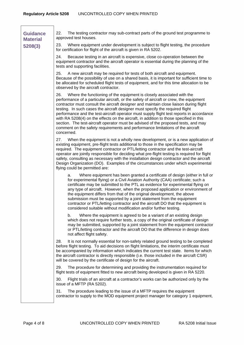
Regulatory Article 5208 UNCONTROLLED COPY WHEN PRINTED
Page 4 of 8 UNCONTROLLED COPY WHEN PRINTED RA 5208 Initial Issue
Guidance Material
5208(3)
22. The testing contractor may sub-contract parts of the ground test programme to approved test houses.
23. Where equipment under development is subject to flight testing, the procedure for certification for flight of the aircraft is given in RA 5202.
24. Because testing in an aircraft is expensive, close co-operation between the equipment contractor and the aircraft operator is essential during the planning of the tests and supporting facilities.
25. A new aircraft may be required for tests of both aircraft and equipment. Because of the possibility of use on a shared basis, it is important for sufficient time to be allocated for scheduled flight tests of equipment, and for this time allocation to be observed by the aircraft contractor.
26. Where the functioning of the equipment is closely associated with the performance of a particular aircraft, or the safety of aircraft or crew, the equipment contractor must consult the aircraft designer and maintain close liaison during flight testing. In such cases the aircraft designer must specify the required flight performance and the test-aircraft operator must supply flight test reports in accordance with RA 5208(4) on the effects on the aircraft, in addition to those specified in this section. The test-aircraft operator must be advised of the proposed tests, and may comment on the safety requirements and performance limitations of the aircraft concerned.
27. When the equipment is not a wholly new development, or is a new application of existing equipment, pre-flight tests additional to those in the specification may be required. The equipment contractor or PTL/letting contractor and the test-aircraft operator are jointly responsible for deciding what pre-flight testing is required for flight safety, consulting as necessary with the installation design contractor and the aircraft Design Organization (DO). Examples of the circumstances under which experimental flying could be permitted are:
a. Where equipment has been granted a certificate of design (either in full or for experimental flying) or a Civil Aviation Authority (CAA) certificate; such a certificate may be submitted to the PTL as evidence for experimental flying on any type of aircraft. However, when the proposed application or environment of the equipment differs from that of the original development, the above submission must be supported by a joint statement from the equipment contractor or PTL/letting contractor and the aircraft DO that the equipment is considered suitable without modification and/or further testing.
b. Where the equipment is agreed to be a variant of an existing design which does not require further tests, a copy of the original certificate of design may be submitted, supported by a joint statement from the equipment contractor or PTL/letting contractor and the aircraft DO that the difference in design does not affect flight safety.
28. It is not normally essential for non-safety related ground testing to be completed before flight testing. To aid decisions on flight limitations, the interim certificate must be accompanied by information which indicates the current test state. Items for which the aircraft contractor is directly responsible (i.e. those included in the aircraft CSR) will be covered by the certificate of design for the aircraft.
29. The procedure for determining and providing the instrumentation required for flight tests of equipment fitted to new aircraft being developed is given in RA 5220.
30. Flight trials of an aircraft at a contractor’s works can be authorized only by the issue of a MFTP (RA 5202).
31. The procedure leading to the issue of a MFTP requires the equipment contractor to supply to the MOD equipment project manager for category 1 equipment,

UNCONTROLLED COPY WHEN PRINTED Regulatory Article 5208
RA 5208 Initial Issue UNCONTROLLED COPY WHEN PRINTED Page 5 of 8
Guidance Material
5208(3)
or to the installation design contractor (with a copy of the covering letter to the PTL for the installation design contractor) for category 2 or 3 equipment, three copies of:
a. An interim certificate of design (RA 5201 suitably annotated for flight trials, or the evidence listed in para. 27.
b. A schedule of installation checks.
c. A schedule of pre-flight functioning checks for the equipment.
32. If the installation design contractor is also the aircraft DO or the test-aircraft operator, he must, after receiving the certificate of design or alternative evidence, certify the equipment installation in accordance with RA 5202. Otherwise he must prepare MOD(CA) Form 100C and submit it to the test-aircraft operator.
33. Where experimental equipment or agreed variants have been developed and extensively flight tested by an MOD establishment, clearance for experimental flying in other aircraft may be by a written statement from the equipment contractor or PTL/letting contractor giving the flight history, and a statement that the equipment is considered sufficiently proven for experimental flying in the proposed application.
34. Unless otherwise specified in the contract a flight includes all taxiing and, in the case of rotary wing aircraft, the rotors developing lift.
Regulation
5208(4)
Test Reports 5208(4) The equipment contractor shall prepare and distribute a
certified and contractor-endorsed test report as soon as possible after completion of tests and post-test examinations.
Acceptable Means of Compliance
5208(4)
35. The test report should identify the item tested and the test equipment employed; it should be certified by a responsible member of the contractor’s test team, and endorsed on behalf of the contractor’s quality organization.
36. The contractor should submit his test report to the PTL and to the Letting Contractor if appropriate.
Guidance Material
5208(4)
37. The typical content of a test report is given in Appendix B.
38. The test reports form part of the total design and performance documentation for the equipment and a list of the reports must be appended to the certificate of design and included in the CSR for the equipment.

Regulatory Article 5208 UNCONTROLLED COPY WHEN PRINTED
Page 6 of 8 UNCONTROLLED COPY WHEN PRINTED RA 5208 Initial Issue
APPENDIX A TYPICAL CONTENT OF DECLARATION OF DEVELOPMENT STANDARD
A.1 The declaration should include: a) Identification of the equipment to be tested.
b) Definition of the design standard to which the equipment conforms (e.g. Specification, drawings
list, etc.).
c) Details of departures from specifications or drawings and the authority for such departures.
d) Declared performance of the equipment, by reference to the test schedule or otherwise.
e) Place and date of manufacture.
f) Contract or sub-contract number.
g) Type of test to be carried out (e.g. Approval or flight clearance).
h) Brief reference to any previous test, either completed or abandoned, on the same type of
equipment.
i) List of any unapproved materials, processes or items used in the manufacture of the equipment,
including reference to evaluation tests or other evidence of their suitability.

UNCONTROLLED COPY WHEN PRINTED Regulatory Article 5208
RA 5208 Initial Issue UNCONTROLLED COPY WHEN PRINTED Page 7 of 8
APPENDIX B TYPICAL CONTENT OF TEST REPORT
B.1 The test report should include:
a) An introduction containing the Data set out in the declaration (where applicable) and showing the
Dates on which the tests were commenced and completed.
b) Summary of contents (if necessary).
c) Brief description of the test equipment used and its calibration status.
d) Results of the tests, correlated with the relevant sections of the test schedule with performance
graphs where appropriate.
e) Records of failures, defects and symptoms of abnormality occurring during tests.
f) Evidence of undue electrical or mechanical stress and results of any strip examination.
g) Reports of any special investigations made after the tests.
h) General comments on the tests.

Regulatory Article 5208 UNCONTROLLED COPY WHEN PRINTED
Page 8 of 8 UNCONTROLLED COPY WHEN PRINTED RA 5208 Initial Issue
Intentionally Blank for Print Pagination
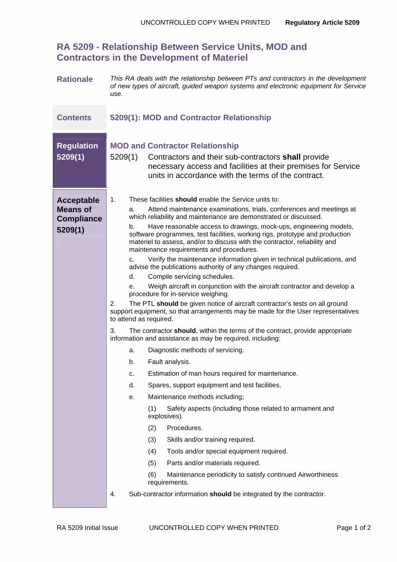
UNCONTROLLED COPY WHEN PRINTED Regulatory Article 5209
RA 5209 Initial Issue UNCONTROLLED COPY WHEN PRINTED Page 1 of 2
RA 5209 - Relationship Between Service Units, MOD and Contractors in the Development of Materiel
Rationale This RA deals with the relationship between PTs and contractors in the development of new types of aircraft, guided weapon systems and electronic equipment for Service use.
Contents 5209(1): MOD and Contractor Relationship
Regulation
5209(1)
MOD and Contractor Relationship 5209(1) Contractors and their sub-contractors shall provide
necessary access and facilities at their premises for Service units in accordance with the terms of the contract.
Acceptable Means of Compliance
5209(1)
1. These facilities should enable the Service units to: a. Attend maintenance examinations, trials, conferences and meetings at which reliability and maintenance are demonstrated or discussed. b. Have reasonable access to drawings, mock-ups, engineering models, software programmes, test facilities, working rigs, prototype and production materiel to assess, and/or to discuss with the contractor, reliability and maintenance requirements and procedures. c. Verify the maintenance information given in technical publications, and advise the publications authority of any changes required. d. Compile servicing schedules. e. Weigh aircraft in conjunction with the aircraft contractor and develop a procedure for in-service weighing.
2. The PTL should be given notice of aircraft contractor’s tests on all ground support equipment, so that arrangements may be made for the User representatives to attend as required.
3. The contractor should, within the terms of the contract, provide appropriate information and assistance as may be required, including:
a. Diagnostic methods of servicing.
b. Fault analysis.
c. Estimation of man hours required for maintenance.
d. Spares, support equipment and test facilities.
e. Maintenance methods including;
(1) Safety aspects (including those related to armament and explosives).
(2) Procedures.
(3) Skills and/or training required.
(4) Tools and/or special equipment required.
(5) Parts and/or materials required.
(6) Maintenance periodicity to satisfy continued Airworthiness requirements.
4. Sub-contractor information should be integrated by the contractor.

Regulatory Article 5209 UNCONTROLLED COPY WHEN PRINTED
Page 2 of 2 UNCONTROLLED COPY WHEN PRINTED RA 5209 Initial Issue
Guidance Material
5209(1)
5. The Service units, which act for servicing and maintainability aspects for the Service departments of MOD, participate in the procurement of materiel from the earliest stages. They provide teams of specialist personnel, who may be resident at contractors, to observe the development and thereby assist its smooth and efficient entry into service. The contractor will be advised by the PTL of the team membership.
6. The Service units and their teams will also provide advice and recommendations on the User(s) use and maintenance of such materiel and will keep their Capability Management and the PTL, informed. Any changes to materiel that are required as a result of such advice or recommendations will need authorizing by the PTL before implementation. If necessary, the contract will be amended.
7. Service unit personnel have no authority to issue instructions to contractors unless authorized to act on behalf of the PTL – such authority will be advised to the contractor by the PTL.

UNCONTROLLED COPY WHEN PRINTED Regulatory Article 5211
RA 5211 Initial Issue UNCONTROLLED COPY WHEN PRINTED Page 1 of 4
RA 5211 - Mock-Ups and Working Rigs
Rationale The contractor may be required to provide and maintain various mock-ups and working rigs during the design and development of a new type or mark of aircraft.
Contents 5211(1): Mock-Ups and Working Rigs Conference
5211(2): Direction on Mock-Ups and Working Rigs
Regulation
5211(1)
Mock-Ups and Working Rigs Conference 5211(1) At an early stage in the design and development, the PTL
shall convene a mock-up and working rigs conference to define, appropriate to the type or mark of aircraft under contract, the mock-up and/or working rigs required.
Acceptable Means of Compliance
5211(1)
1. The Mock-Ups and Working Rigs Conference should be attended by representatives of MOD, the aircraft contractor and other contractors involved.
2. The conference report should be prepared by the contractor and after approval by the PTL should be issued to all concerned.
3. Subsequent meetings should be convened by the PTL to discuss detailed requirements for specific mock-ups and/or working rigs.
Guidance Material
5211(1)
4. Details of items to be included in full mock-ups and the purposes for which the mock-ups will be used are detailed in Appendix A.
5. Detailed proposals for specific working rigs and the operating conditions to be simulated are given in Appendix B.
Regulation
5211(2)
Direction on Mock-Ups and Working Rigs 5211(2) The contractor shall adopt the decisions of the mock-up and
working rig conference unless they are at variance with the terms of the contract, in which case the contractor shall await authority from the PTL before proceeding.
Acceptable Means of Compliance 5211(2)
6. The contractor, if required by the conference, should make a preliminary mock-up as early as possible to demonstrate the general layout of the aircraft. 7. As soon as the design of the aircraft has become reasonably stable, the contractor, if required by the conference, should make a full mock-up. This mock-up should be of substantial construction and dimensionally accurate. 8. The PTL and the contractor should agree the materials from which this mock-up should be constructed. 9. The contractor, if required by the conference should also make any additional mock-ups.
Regulatory Article 5211 UNCONTROLLED COPY WHEN PRINTED
Page 2 of 4 UNCONTROLLED COPY WHEN PRINTED RA 5211 Initial Issue
Acceptable Means of Compliance
5211(2)
10. Mock-ups should be kept up-to-date to facilitate assessment of new requirements and should be retained until the Final Examination and Conference and as long thereafter as required by the PTL. The need to retain and keep up-to-date specific mock-ups should be reviewed at regular intervals by the PTL in consultation with the contractor.
11. The contractor, if required by the conference should provide working rigs of the aircraft systems and installations.
12. Alterations to systems and installations that are found necessary during the design and development should be incorporated.
13. The contractor and, where appropriate, his sub-contractors should prepare and issue reports on tests carried out on working rigs as soon as possible after the tests have been completed. When completion of the tests on a rig is likely to be unduly delayed, an interim report should be issued.
14. Working rigs should be maintained by the contractor until otherwise agreed by the PTL or terminated by the terms of the contract.
Guidance Material
5211(2)
Direction on Mock-Ups and Working Rigs 15. Details of items to be included in full mock-ups and the purposes for which the mock-ups will be used are detailed in Appendix A.
16. Detailed proposals for specific working rigs and the operating conditions to be simulated are given in Appendix B.

UNCONTROLLED COPY WHEN PRINTED Regulatory Article 5211
RA 5211 Initial Issue UNCONTROLLED COPY WHEN PRINTED Page 3 of 4
APPENDIX A FULL MOCK-UPS
1 Introduction
The full mock-up must include the engine installation, indicating the composition of the engine change unit (ECU), and must be fitted with the items of equipment listed in the aircraft Appendix A (see RA 5214). Space models may be used to represent an item when the actual equipment is not available, or by agreement with the PTL. Additionally, the mock-up must include sufficient mainplane, undercarriage, tail structure, etc. for such purposes as:
a) Co-ordinating requirements of PT's, Users and Special Advisers and of aircraft, engine and equipment contractors.
b) Determining layout of crew stations.
c) Investigating field of view for take-off, flying and landing and for sensors (e.g. For weapon aiming system(s), cameras etc.).
d) Checking layout of systems and equipment installations (e.g. Instrument panel lighting, location of aerials, and absence of obstructions to weapon firing and release).
e) Checking proposed methods of abandoning the aircraft in flight and after a crash/ditching.
f) Assessing servicing (e.g. Access for in-situ servicing and testing, and for removal and refit; clearances for loading and off-loading weapons and armament; harmonisation of equipment and of sensors).
g) Initial preparation of technical publications.
h) Proving trial installations of new or modified items of equipment when appropriate.
Regulatory Article 5211 UNCONTROLLED COPY WHEN PRINTED
Page 4 of 4 UNCONTROLLED COPY WHEN PRINTED RA 5211 Initial Issue
APPENDIX B WORKING RIGS
1 Working rigs may include equipment to:
a) Represent a range of ambient conditions.
b) Prove system functioning.
c) Prove reliability.
d) Conduct life tests.
e) Conduct fatigue tests.
f) Investigate fault conditions.
g) Determine effects of mishandling.

UNCONTROLLED COPY WHEN PRINTED Regulatory Article 5212
RA 5212 Initial Issue UNCONTROLLED COPY WHEN PRINTED Page 1 of 4
RA 5212 - Mass, CG and Associated Data of Aircraft
Rationale This RA sets out the requirements for the preparation and reporting by the contractor of the mass, centre of gravity and other data of aircraft, using the ‘Aircraft Mass Properties and Design Data’ form (Refer to the MAA), and for the standards of accuracy required.
Contents 5212(1): Submission of Data
5212(2): Mass and Centre of Gravity (CG) Determination
Regulation
5212(1)
Submission of Data 5212(1) The Aircraft Mass Properties and Design Data form (CA(PE)
Form 76) shall be prepared for each type of aircraft as soon as possible after, and in any event within twelve months of, the date of the development contract, unless an extension to the initial twelve months has been agreed by the PTL.
NOTE: The CA(PE) Forms are now discontinued. The MAA is investigating the value of this form to the MOD. Consult the MAA before gathering the data required.
Acceptable Means of Compliance 5212(1)
1. Requests for specimens of the form should be made to the MAA.
2. In addition, group Mass statements (RA5214 Figure 001 and 002) and Mass Data for costing pages (RA5214 Figure 003 and 004) of the Aircraft Mass Properties and Design Data, should be prepared and distributed every three months from the date of the contract until initial aircraft Release To Service (RTS).
3. Until accurate details are available from production aircraft, the data quoted should be the best estimates for the first representative production aircraft to enter Service, taking into account any data derived from the weighing of development aircraft.
4. For each new build research aircraft a complete Aircraft Mass Properties and Design Data form should be prepared and distributed after the mass has been determined by weighing. Periodic re-submissions are not required for such aircraft unless specially called for by the PTL.
5. For aircraft undergoing refurbishing or reconditioning Aircraft Mass Properties and Design Data form are not required, but such aircraft should have their mass determined by weighing, and a simple statement of the basic mass based on the average value should be prepared and distributed.
6. Aircraft Mass Properties and Design Data, and Mass statements (paragraphs 3 and 4) should be supplied to the PTL.
7. The form should be brought up to date and re-distributed at twelve-monthly intervals from the date of first submission until production ceases. In this context, each type of aircraft includes initial and successive marks of new build aircraft, conversions to new marks and derivatives of civil aircraft, but excludes research aircraft and aircraft undergoing refurbishing/reconditioning.
Regulatory Article 5212 UNCONTROLLED COPY WHEN PRINTED
Page 2 of 4 UNCONTROLLED COPY WHEN PRINTED RA 5212 Initial Issue
Guidance Material
5212(1)
8. The requirements for Mass, CG and Associated data for engines are detailed in RA 5607.
Regulation
5212(2)
Mass and Centre of Gravity (CG) Determination 5212(2) The contractor shall determine the mass of each aircraft by
weighing before final delivery.
Acceptable Means of Compliance
5212(2)
9. The mass and CG position relating to the basic and all-up mass conditions (allowing for equipment deviations) should be reported to the PTL.
10. The vertical CG positioning should be measured on one of the first ten representative aircraft and thereafter as requested by the PTL.
11. The contractor should ensure that:
a. For aeroplanes:
(1) The measured basic mass of the aircraft (i.e. less fuel, payload and/or items of equipment), is accurate within ± 0.3%.
(2) The horizontal CG position, measured normal to the vertical Datum line is accurate within ± 5% of the practical CG range.
(3) The vertical CG position is measured to an accuracy agreed between the contractor and the PTL.
b. For rotorcraft:
(1) The measured basic mass of the aircraft, is accurate within ± 0.3%.
(2) The horizontal CG position is measured normal to the vertical datum line to the accuracy given in Appendix A.
(3) The vertical CG position is measured normal to the horizontal datum line to the accuracy given in Appendix A.
(4) The lateral CG position is measured normal to the longitudinal axis of the aircraft to the accuracy given in Appendix A.
12. To provide information on the weighing of the aircraft in the field, one aircraft should be weighed using in-service hydrostatic weighing equipment. The Contractor should liaise with the PTL to facilitate the attendance of the relevant in-service aircraft weighing team representative.
13. The position of the datum lines and points of origin should be quoted in the Certificate for Flight Trials (RA5202). The basic mass and moment of each aircraft should be recorded on the appropriate aircraft documents.
Guidance Material
5212(2)
12. The contractor may use any suitable method of weighing which achieves the required accuracy.
13. The requirements for Mass, CG and Associated data for engines are detailed in RA 5607.
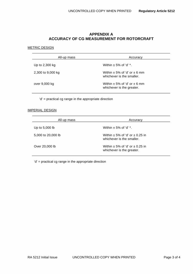
UNCONTROLLED COPY WHEN PRINTED Regulatory Article 5212
RA 5212 Initial Issue UNCONTROLLED COPY WHEN PRINTED Page 3 of 4
APPENDIX A ACCURACY OF CG MEASUREMENT FOR ROTORCRAFT
METRIC DESIGN
All-up mass Accuracy Up to 2,300 kg 2,300 to 9,000 kg over 9,000 kg
Within ± 5% of ‘d’ *. Within ± 5% of ‘d’ or ± 6 mm whichever is the smaller. Within ± 5% of ‘d’ or ± 6 mm whichever is the greater.
‘d’ = practical cg range in the appropriate direction IMPERIAL DESIGN
All-up mass Accuracy Up to 5,000 lb 5,000 to 20,000 lb Over 20,000 lb
Within ± 5% of ‘d’ *. Within ± 5% of ‘d’ or ± 0.25 in whichever is the smaller. Within ± 5% of ‘d’ or ± 0.25 in whichever is the greater.
‘d’ = practical cg range in the appropriate direction

Regulatory Article 5212 UNCONTROLLED COPY WHEN PRINTED
Page 4 of 4 UNCONTROLLED COPY WHEN PRINTED RA 5212 Initial Issue
Intentionally Blank for Print Pagination

UNCONTROLLED COPY WHEN PRINTED Regulatory Article 5213
RA 5213 Initial Issue UNCONTROLLED COPY WHEN PRINTED Page 1 of 2
RA 5213 - Final Examinations and Conferences
Rationale The purpose of a final examination is to check physically that the aircraft and its installations are satisfactory.
Contents 5213(1): Aircraft Standard
Regulation
5213(1)
5213(1) The aircraft presented for final examination shall be fully equipped in accordance with the aircraft specification, including the accepted Appendix A (RA 5214) to the aircraft specification.
Acceptable Means of Compliance
5213(1)
1. Any amendments to the Appendix A (RA 5214) accepted up to one month prior to the date of presentation of the aircraft for final examination, and any previous examination reports should be included as part of the aircraft presented.
2. The Contractor/Design Organization (DO) should provide facilities at his works for the final examination of the selected aircraft to be made on behalf of the MOD. The contractor should advise the PTL of the date by which the aircraft will be ready for the final examination, which should be made as soon as possible after the aircraft has passed the inspection required by the PTL quality representative for this purpose.
3. Items of non-standard ancillary equipment which the DO has to supply with the aircraft should be available for inspection at the final examination, and if so required, the designer should demonstrate their use.
4. When production aircraft are to be delivered with certain items of equipment missing, the DO should show that these items can be fitted correctly, and that the runs and lengths of wiring, piping, etc. associated with these items are satisfactory. If ballast, temporary wiring looms etc. are required in lieu of missing equipment, these should be displayed and fitted if so requested.
Guidance Material
5213(1)
5. The final examination is required for both pre-production and production aircraft. The final conference formally considers all aspects of the aircraft design and takes decisions on any unresolved comments outstanding from the relevant engineering observations and reports presented by the PTL quality representative on new type aircraft, aircraft equipment and trial installation modifications. Such decisions of the final conference are subject to the satisfactory completion of the outstanding development trials and acceptance trials.
6. If so required, the DO must take out the removable equipment forming part of the military load, and must fit the alternative items which are detailed in the aircraft specification; or he must demonstrate that the alternative items can be fitted satisfactorily.
7. The DO must be notified by the PTL of any Service supply/Service fit items which are required to be fitted to the aircraft submitted for final examination. The DO must demand such items in accordance with the procedures detailed in the 5500 Series of RAs.
8. Reports on the final examinations and conferences must be prepared by the Contractor for the PTL (RA 5211 refers).

Regulatory Article UNCONTROLLED COPY WHEN PRINTE
Page 2 of 2 UNCONTROLLED COPY WHEN PRINTED RA Initial Issue
Intentionally Blank for Print Pagination

UNCONTROLLED COPY WHEN PRINTED Regulatory Article 5214
RA 5214 Initial Issue UNCONTROLLED COPY WHEN PRINTED Page 1 of 8
RA 5214 - Schedule of Equipment - Appendix A to the Aircraft Specification
Rationale The Appendix A to the Aircraft Specification is required primarily for provisioning purposes and lists all items of equipment, irrespective of supply and fit categories, which will have to be provisioned for installation in new, repaired or converted service aircraft and as spares for maintenance purposes.
Contents 5214(1): Preparation and Submission of an Appendix A
Regulation
5214(1)
Preparation and Submission of an Appendix A 5214(1) The aircraft contractor shall prepare a draft Appendix A to
the Aircraft Specification for a new type or mark of aircraft when so instructed by the PTL, or when invited by the MOD to submit a quotation for the aircraft.
Acceptable Means of Compliance
5214(1)
1. A draft Appendix A should be arranged in the following sections:
a. Section A – Armament.
b. Section B – Electrical.
c. Section C - Instrument (including oxygen equipment).
d. Section D - Aircraft services and miscellaneous.
e. Section E - Radio/radar.
f. Section F - Power unit.
g. Section G - Special-to-type equipment which is sometimes installed in the aircraft.
h. Section H - Reserved for special equipment. (This section may be separate; it will have a special and restricted distribution).
2. Section D should include subsections covering the following assemblies and items:
a. Aircrew equipment assembly (AEA).
b. Undercarriage, wheels, brakes and tyres.
c. Flying controls.
d. Hydraulics and pneumatics.
e. Cabin pressurization and air conditioning systems.
f. Any other system such as the fuel system, as appropriate.
g. Miscellaneous.
3. The subsection covering the AEA should be based on a schedule prepared by the MOD Aircrew Escape & Survival (AES) PT for including in AP 108B-0001-1. The subsection should include an aircraft list (i.e. ejection seats, rails, seat harness, sockets fixed to the seat or aircraft), and include a cross-reference to the aircrew list (i.e. all items worn by the aircrew members and plugs or corresponding parts which are attached to sockets fixed to the seat or aircraft), and the specialist role list if relevant.

Regulatory Article 5214 UNCONTROLLED COPY WHEN PRINTED
Page 2 of 8 UNCONTROLLED COPY WHEN PRINTED RA 5214 Initial Issue
Acceptable Means of Compliance
5214(1)
4. The draft Appendix A should bear a serial number. This number will be provided by the PTL, unless the number is given in the aircraft specification.
5. The composition of a draft Appendix A should be similar to that of the accepted Appendix A (Figures 1, 2 and 3) except that no provision need be made for binding, spine card, title page, amendment record or modification record.
6. If the delivery of an aircraft to the authorized standard of Appendix A equipment would involve serious delay, deviations are in certain circumstances permitted on the authority of the PTL. For this purpose the aircraft contractor should prepare and submit to the PTL a request listing deviations.
7. Deviation requests should be prepared and distributed in accordance with Def Stan 05-61 Part 1.
8. The aircraft contractor should provide a draft Appendix A for a production aircraft to the PTL, for distribution to all stakeholders in MOD for comment, prior to an Appendix A acceptance meeting.
9. Amendments to a draft Appendix A should not be made between the date of issue and the acceptance meeting as this does not give adequate time for consideration by MOD staff. The procedure of RA 5214(3) should therefore be followed for all amendments.
10. Proposed amendments to an accepted Appendix A (other than those referred to in paragraphs 11 and 12) should be submitted to the PTL for acceptance. The preparation of amendments remains a continuing requirement throughout the service life of an aircraft.
11. Draft amendments involving changes to the equipment arising before the introduction of airframe modification procedure, but after submission of the draft Appendices A to the PTL, should be submitted to the PTL in the same manner as new draft Appendices A.
12. Draft amendments involving changes to the equipment arising after the introduction of modification procedure should be forwarded direct to the PTL and cross-referred to the relevant modification number.
13. Draft amendments involving no changes to equipment (e.g. those containing amplification of part numbers, stores reference numbers etc.) should be forwarded direct to the PTL.
14. The PTL should in each case notify the contractor of the acceptance of the amendments. The date of this notification is the effective date of the amendment.
Guidance Material
5214(1)
15. An Appendix A must contain:
a. A spine card for use with a standard loose-leaf binder.
b. A title page (for an example see Figure 1).
c. An amendment record.
d. A modification record.
e. Introductory sheets (for an example see Figure 2).
f. An index of sections.
g. An index of items (alternatively, each section may contain an index of the items within that section).
h. The sections listed in paragraph 1 prepared to the requirements of the PTL. A typical layout is shown in Figure 3.
16. The introductory sheet must list code letters designating the roles of the aircraft. These code letters must be inserted in column 10 of the draft Appendix A against

UNCONTROLLED COPY WHEN PRINTED Regulatory Article 5214
RA 5214 Initial Issue UNCONTROLLED COPY WHEN PRINTED Page 3 of 8
Guidance Material
5214(1)
Service fit and other appropriate items. Where necessary a key sheet may be added to the introductory sheet co-relating the contractor’s development batch numbers with the aircraft serial numbers.
17. For all items proposed as contractor supply which can be obtained from one manufacturer only, the name of the manufacturer must be shown in column 3 of the draft Appendix A.
18. All items in the Appendix A must be listed under the appropriate section, with a cross-reference if necessary to the major item or system in or to which they are fitted: such items shall also be shown under the major item or system with the annotation ‘see section. . . . . .’, and with columns 7 and 9 left blank.
19. The list of items constituting an engine or engine module is defined in the specification for the engine or engine module. The Appendix A for the aircraft therefore may include only a cross-reference to this specification.
20. An Appendix A will be amended when changes in the supply category of an item of equipment are authorized by the PTL. Such authorisations may require Contract action if the change is temporary or if special considerations apply.
21. The quantity required per aircraft of each item will be stated in column 7 or column 9 of the draft Appendix A, as appropriate. (See Figures 1, 2 & 3 for column definition and typical layout).
22. The schedule of equipment is called up in the specification or contract for an aircraft, and is the Appendix A to the aircraft specification. The schedule of equipment is also issued as the Topic 3B of the aircraft publications (APs).
23. The Appendix A is issued under the authority of the PTL. The contractor who will normally be the Design organization (DO) will be required to distribute the approved Appendix A, and amendments, to a list of addressees provided by the PTL.
24. Each item included in an Appendix A, even though it may be a component of another item or system, is regarded as an equipment item in its own right; it is therefore subject to the design certification requirements of the 5100 series RAs.
25. It is essential that from the earliest stages in an Appendix A the fullest available identification should be given to each item:
a. To enable the certification of design status to be checked.
b. For inspection purposes.
c. For spares provisioning purposes.
26. The Appendix A, which is required primarily for provisioning purposes and lists all items of equipment, irrespective of supply and fit categories, details all the equipment installed in the aircraft, which requires certification, comprising:
a. All Service supply items.
b. All contractor supply items.
c. Contractor’s airframe items which are fitted by the service for a certain role or roles, but not for all roles.
d. Special-to-type ancillary equipment which is sometimes installed in the aircraft (but excluding other items of ground equipment).
27. Acceptance by the PTL of the Appendix A, or of amendments, is the aircraft contractor’s authority (as provided in the relevant contract for the supply of the aircraft) for provisioning those items of aircraft equipment which are listed as contractor supply and for demanding from the Service department of MOD those items which are listed as Service supply for incorporation by the contractor in the aircraft (paragraph 31). Acceptance of the Appendix A also enables the Service department concerned to take requisitioning action in respect of Service supply items and all items required as spares.

Regulatory Article 5214 UNCONTROLLED COPY WHEN PRINTED
Page 4 of 8 UNCONTROLLED COPY WHEN PRINTED RA 5214 Initial Issue
Guidance Material
5214(1)
28. The number of copies of the draft Appendix A to be provided by the aircraft contractor will be specified by the PTL.
29. Printing and distribution of the accepted Appendix A and subsequent amendments will be the responsibility of the aircraft contractor. The PTL will provide the list of addressees and the number of copies required by each addressee.
30. For production aircraft, copies of the draft Appendix A will normally be required before a contract is placed. Where it is known that pre-production aircraft will be followed by production aircraft, the contract for the pre-production aircraft will include a requirement for a draft Appendix A for production aircraft.
31. The aircraft contractor is entitled to demand all items which are listed in an accepted Appendix A as Service supply/contractor fit items, otherwise known as Contract Embodiment Items (CEI). The procedure for demanding such equipment is given in the 5500 Series RAs.
32. Service fit items can also be demanded on loan for the purpose of final conference (RA 5313).
33. The Appendix A acceptance meeting will be arranged by the PTL. The representatives of the aircraft contractor will be invited.
34. The draft Appendix A will be reviewed to:
a. Take account of comments submitted previously to the PTL, or tabled at the meeting, on technical, financial, operational or maintenance aspects or availability of the items listed.
b. Decide the supply and fit categories for each item of equipment.
c. Identify and list those items which require certification of design; 5100 series RAs refers. For equipment which is Service supply/CEI, certificates of design will be provided by the PTL.
35. A copy of the minutes of the acceptance meeting will be sent to the aircraft contractor, to record the acceptance of the draft Appendix A, the authorized equipment standard for the aircraft, the agreed basis of provisioning of all items of equipment to be installed in the aircraft, and the items requiring certification of design.
36. After completion of the initial production run of the aircraft the PTL may request the contractor to delete certain minor items from the Appendix A.

Regulatory Article 5214 UNCONTROLLED COPY WHEN PRINTED
Page 5 of 8 UNCONTROLLED COPY WHEN PRINTED RA 5214 Initial Issue
88
FIGURE 1 EXAMPLE OF A TITLE PAGE OF AN APPENDIX A
THIS DOCUMENT IS THE PROPERTY OF HM GOVERNMENT
This document is intended for the use of the recipient only and may be used only in connection with work carried out for or on behalf of HM Government. The unauthorized retention or destruction of this document, or the disclosure of its contents to any unauthorized person, is forbidden.
Attention is hereby called to the fact that failure to comply with any of the above instructions is an infraction of the Official Secrets Act.
NOTE: Any person other than the authorized holder upon obtaining possession of this document by finding or otherwise should forward it, together with his name and address, in a closed envelope to: MINISTRY OF DEFENCE, ABBEYWOOD BRISTOL. Letter postage need not be prepaid; other postage will be refunded.
APPENDIX A SERIAL NO
SCHEDULE OF EQUIPMENT
FOR
(AIRCRAFT NOMENCLATURE)
AIRCRAFT
NOTES: 1. Distributed on behalf of MOD-(insert the title of the relevant MOD Aircraft PTL) by:-(insert name and address of aircraft contractor). 2. Distribution queries to:-(insert contact point, and telephone number of the aircraft contractor).
3. Enquiries regarding the content of this Appendix A should be made to:-(insert the title, address and telephone number of the MOD Aircraft PTL).

UNCONTROLLED COPY WHEN PRINTED Regulatory Article 5214
RA 5214 Initial Issue UNCONTROLLED COPY WHEN PRINTED Page 6 of 8
FIGURE 2 EXAMPLE OF AN INTRODUCTORY SHEET OF AN APPENDIX A
APPENDIX A SERIAL N
Air Publication No:
Aircraft Type: Mark No: Specification No:
Appendix A Prepared by: Date:
Appendix A Approved by: Date:
List of Roles The roles covered by this Schedule are: Primary Secondary Index of Sections and Items see Pages Standard Symbols for Supply and Fit Categories
C/C Contractor Supply/Contractor Fit C/S Contractor Supply/Service Fit CPS/C Contractor Supply, previously Service Supply/Contractor Fit CPS/S Contractor Supply, previously Service Supply/Service Fit CSO/C Contractor Supply to Special Order Only/Contractor Fit CSO/S Contractor Supply to Special Order Only/Service Fit

Regulatory Article 5214 UNCONTROLLED COPY WHEN PRINTED
Page 7of 8 UNCONTROLLED COPY WHEN PRINTED RA 5214 Initial Issue
FIGURE 2 EXAMPLE OF AN INTRODUCTORY SHEET OF AN APPENDIX A
Standard Symbols for Supply and Fit Categories (Cont’d)
MOD/C Supplied from MOD Sources/Contractor Fit PIA Personal Issue to Crew S/C Service Supply/Contractor Fit S/S Service Supply/Service Fit SSO/C Service Supply to Special Order Only/Contractor Fit SSO/S Service Supply to Special Order Only/Service Fit
A This prefix to any ‘S’ or ‘SSO’ supply symbol indicates that the item is supplied by the Ministry of Defence (Army Dept).
N This prefix to any ‘S’ or ‘SSO’ supply symbol indicates that the item is supplied by the Ministry of Defence (Navy Dept).
M This prefix to any symbol for a Service Fit item means that the item must not be fitted by the aircraft contractor in any circumstances .
Columns
Columns used in Appendices A are defined as follows:
Col 1 Item Number Col 2 Reference Number Col 3 Description Col 5 Supply Category Col 6 Fit Category Col 7 Quantity (items transferred with complete aircraft) Col 9 Quantity (Unit equipment) Col 10 Role or Roles Col 11 Specification, or MRI/DIS Number or Mod Number

UNCONTROLLED COPY WHEN PRINTED Regulatory Article 5214
RA 5214 Initial Issue UNCONTROLLED COPY WHEN PRINTED Page 8 of 8
FIGURE 3 TYPICAL LAYOUT OF AN APPENDIX A
SECTION ‘C’ INSTRUMENTS
1 2 3 5 6 7 9 10 11
ENGINE INSTRUMENTS (Continued)
INDICATORS, Water Contents, Page Engineering Ltd:
88 6A/6610-99-114-2400 Part No. B.4900/0053 C C 1 Mod. 82 89 6A/6610-99-114-2401 Part No. B.4900/0053 C C 2 Mod. 78
Accessories:
Clamp Securing:
FIGURE 390
6A/5975-99-700-2039 Smith Type STD.1503 (was 6A/5633)
C C 1
91 6A/5975-99-700-2040 Smith Type STD 1504 (was 6A/5634)
C C 2
TACHOMETER, Engine Speed:
92 6A/58764 Mk.32 S C 2 Mod. 286
FLYING INSTRUMENTS
6A/45678 ALTIMETERS: 93 Mk.36 S C 2
6A/ COMPUTER, Air Data, S Smith Ltd:
94 Type 1204 KHA/1 C C 1 Switches Airspeed:
95 Refer to Section B Electrical 6B/4089 WATCHES Stop, Convair Time Ltd: ED. Hour, Dashboard Type S S 1 A,B

UNCONTROLLED COPY WHEN PRINTED Regulatory Article 5215
RA 5215 Initial Issue UNCONTROLLED COPY WHEN PRINTED Page 1 of 10
RA 5215 - Provision of Miscellaneous Data during Development
Rationale During the design and development of an aircraft and certain installed equipment the aircraft contractor will be required to supply certain miscellaneous Data required for testing and evaluating the aircraft, and to assist the User to operate the aircraft. This RA gives details of the Data required.
Contents 5215(1): Drawings of Systems for which a Working Rig is Required
5215(2): Models
5215(3): Information required for Maintenance, Stowage and Transport of Aircraft Components.
5215(4): External Colouring and Marking Drawings
5215(5): Armament Installation
5215(6): Armament Wiring Quality Assurance
5215(7): Torpedoes
5215(8): Weapon Harmonization
5215(9): Software (Program) Documentation
Regulation
5215(1)
Drawings of Systems for which a Working Rig is required 5215(1) The contractor shall supply to the PTL provisional drawings
of the systems which are the subject of working rigs (RA5211). The drawings shall be available one month before the date of the mock-up or working rig conference.
Regulatory Article 5215 UNCONTROLLED COPY WHEN PRINTED
Page 2 of 10 UNCONTROLLED COPY WHEN PRINTED RA 5215 Initial Issue
Acceptable Means of Compliance
5215(1)
1. Within one month after the mock-up examination the contractor should supply to the PTL two copies of the following diagrammatic sketches or photographs, each of which should show main systems and equipment, e.g. seats, tanks, controls, main and tail rotor transmission systems, as necessary:
a. View of skeleton structure and outline of fuselage showing views of the equipment in position on the port and starboard side of the aircraft.
b. A plan view of all equipment in position.
c. Full view of the layout of instrument panels, consoles and switchboards.
d. A schedule of equipment indexed to correspond with ‘balloon’ pointers in the sketches. A spare column should be provided for notes or alterations.
2. When the aircraft is handed over for type trials, and similarly for any subsequent aircraft if substantially different from the first, the contractor should supply to the PTL, two copies of the general arrangement (GA) drawing of the completed aircraft, and two copies of the GA drawings showing the layout of all the equipment. For pre-production aircraft the information should be provided as soon as it becomes available. For production aircraft the information should be supplied when the contract is placed, thereafter further copies, giving any information which may not have been available previously, or has been amended, should be supplied quarterly until the first production aircraft has been delivered, when the final issue together with drawings in any acceptable form agreed with the PTL should be supplied. Whenever modifications which change the information already given are approved for production aircraft, copies of the revised drawings should be supplied.
3. Where the aircraft specification requires the aircraft to be operated from ships, stowed in ships or to be air-portable, seven prints of GA drawings dimensioned relevant to operation, deck handling, servicing, picketing, stowage and portability aspects should be supplied to the PTL.
Guidance Material
5215(1)
4. Nil
Regulation
5215(2)
Models 5215(2) When required for use by PTL the contractor shall supply a
scale model or models, or the drawings and Data necessary for the construction thereof.
Acceptable Means of Compliance 5215(2)
5. The contractor should supply the model(s) suitable for: a. Wind tunnel tests. b. Spinning tests, where the characteristics of the aircraft may involve spinning. c. Any special tests which may be required (e.g. free flight, flutter and air intake).
6. Such models provided by the contractor for wind tunnel and other tests should be constructed in accordance with the recommendations of the testing agency identified by the PTL. 7. When a contractor wishes to arrange for wind tunnel or other tests, but has not suitable facilities for such tests, he should consult the PTL.

UNCONTROLLED COPY WHEN PRINTED Regulatory Article 5215
RA 5215 Initial Issue UNCONTROLLED COPY WHEN PRINTED Page 3 of 10
Guidance Material
5215(2)
8. Nil
Regulation
5215(3)
Information Required for Maintenance, Stowage and Transport of Aircraft Components 5215(3) To assist the Services in their organization of the
maintenance, stowage and transport of aircraft components, the relevant information shall be provided for the major components of each new type of aircraft.
Acceptable Means of Compliance
5215(3)
9. The following information should be provided (Appendix A provides an example list of main airframe components):
a. The spaces occupied by packaged and unpackaged components.
b. The masses of packaged and unpackaged components.
c. The shelf life and any maintenance required during storage.
d. The times necessary (i.e. number of men, man-hours and elapsed time) for removing each main component from the aircraft and refitting it.
NOTE The information of 9.d) above may not be available at the same time as a., b. and c., and if so, this information should be forwarded when available, but not later than the delivery date of the first production aircraft.
10. The information should be presented on two sheets. Examples showing the layout required, are given in Appendix B and Appendix C. For simplicity, views of components should show only the general shape. Normally one view will be sufficient, except for components where the shape is unusual or cannot be visualized without the aid of a second view.
11. The drawings should be prepared at the earliest possible stage in the design. The information on dimensions, masses and man-hours should be inserted by the contractor. The masses of packaged components should indicate the masses both in standard and restricted packages, the latter being used for home issues.
12. Two reproducible copies of the first issue of the drawings, in an agreed format, should be forwarded to the PTL as soon as the overall dimensions of the main components of production aircraft are known. Estimated masses, indicated as such, should be included, if possible.
13. The dimensions to be inserted in the tabular statement should allow for any fittings, such as control surface levers or fork ends, which are not readily removable.
14. Amended copies of the drawings, each with a new issue number, should be forwarded to the PTL as changes are made to the drawings or data.
Guidance Material
5215(3)
15. Nil

Regulatory Article 5215 UNCONTROLLED COPY WHEN PRINTED
Page 4 of 10 UNCONTROLLED COPY WHEN PRINTED RA 5215 Initial Issue
Regulation
5215(4)
External Colouring and Marking Drawings 5215(4) Contractors shall prepare for each aircraft type dimensional
drawings giving full instructions for the application of a colour scheme and markings.
Acceptable Means of Compliance
5215(4)
16. The information given on the drawings should include:
a. Paint scheme specification.
b. The official colour titles and specification numbers.
c. Particulars of any masks or templates required.
17. The drawings should be submitted to the PTL, and after receiving approval should be included in the Configuration Status Record (CSR) as the standard for production, repair and reconditioning.
Guidance Material
5215(4)
18. The external colouring and marking requirements for Service aircraft are detailed in AP 119A-0601-0 which gives particulars of camouflage and other colour schemes, servicing, safety and access markings.
Regulation
5215(5)
Armament Installation 5215(5) As early as possible in the design stage and before detailed
design commences, the contractor shall supply to the PTL four sets of drawings, and any subsequent changes, of the proposed armament installation (5100 series RAs refer).
Acceptable Means of Compliance
5215(5)
19. The contractor should supply to the PTL full particulars of the armament installation and the location of armament stores, in the form of GA drawings and detail drawings and schedules (four complete sets). The drawings should include details of all equipment supplied by the contractor to meet the relevant requirements of Def Stan 00-970 Part 1, Section 9, Part 7 Section 7 or Part 9 Section 4 and should indicate the position and outline of all items of Service supply or Contract Embodiment Item (CEI) equipment. The GA drawings should also indicate the ground and deck clearances in the various conditions required by Def Stan 00-970 Part 1, Section 4.13, or Part 7, Section 3.
20. The contractor should also supply to the PTL, as soon as they are available, four sets of the wiring diagrams for the armament electrical installation, including details of all armament junction boxes or other units that are not Service supply or CEI, and the proposed routing of the cable looms to permit an independent appraisal of the installation to take place. These diagrams should show clearly details of all plugs and sockets, terminal junctions, the size and type of cable and the make and part numbers of all components. These diagrams should be accompanied by calculations showing the voltage to be expected at the input terminals of the various operating devices, under both normal and emergency conditions.
21. Before the final conference, the contractor should supply to the PTL a statement detailing all drawings and their issue number affecting the armament installation.

UNCONTROLLED COPY WHEN PRINTED Regulatory Article 5215
RA 5215 Initial Issue UNCONTROLLED COPY WHEN PRINTED Page 5 of 10
Guidance Material
5215(5)
22. Nil
Regulation
5215(6)
Armament Wiring Quality Assurance 5215(6) As soon as the wiring of the first aircraft has been completed
to the satisfaction of the PTL, the contractor shall prepare location and routing drawings in sufficient detail to ensure that there will be no variation between aircraft.
Acceptable Means of Compliance
5215(6)
23. Appropriate drawings and photographs should be prepared for any armament junction boxes or other units that are not Service supply or CEI.
Guidance Material
5215(6)
24. Photographs may be used provided that they can be included in the design records in accordance with the 5300 series RAs.
Regulation
5215(7)
Torpedoes 5215(7) The contractor shall supply to the PTL curves showing the
angle of the longitudinal axis of the torpedo related to the flight path of the aircraft in level flight at different speeds for full operational load with: a. Full fuel load. b. Half fuel load. c. 10% fuel load.
Acceptable Means of Compliance
5215(7)
25. This information should be supplied at an early stage in the design and may be based on wind tunnel model tests or estimates. In addition the angle between the axis of the installed torpedo and the datum line of the aircraft should be stated.
26. If air brakes are fitted a second series of curves should be supplied covering the above cases with brakes fully extended.
27. Two sets of all drawings, schedules and curves should also be supplied to DES WpnsTorps-1, Torpedoes PT, MOD Abbey Wood, Bristol BS34 8JH.

Regulatory Article 5215 UNCONTROLLED COPY WHEN PRINTED
Page 6 of 10 UNCONTROLLED COPY WHEN PRINTED RA 5215 Initial Issue
Guidance Material
5215(7)
28. Nil.
Regulation
5215(8)
Weapon Harmonization 5215(8) For aircraft fitted with guns, guided missiles or rocket
projectiles, the contractor shall supply relevant information to the PTL.
Acceptable Means of Compliance
5215(8)
29. The contractor should supply the following information, which is required for harmonization purposes:
a. Attitude to the flight path of the horizontal fuselage datum (or wing datum) from stalling to maximum permissible speed in steady 1g flight. The information is required over the full range of altitude and is to indicate the Mach No effect at a given indicated airspeed. The aircraft all-up-mass should cover the normal operating range with a typical service load with full armament equipment.
b. The relation between the attitude of the wing mean chord at the launcher and the horizontal fuselage datum over the above range of conditions.
c. The centre lines of guns, guided missile and rocket launchers relative to the horizontal fuselage datum and the wing datum, when the aircraft is in the static harmonization condition wheels on the ground, and when the aircraft is supported on jacks with the wheels off the ground.
d. The effect of applied accelerations in excess of 1g on the attitude of the local wing datum due to wing twisting.
e. All dimensions for the armament and sighting installations relative to the horizontal fuselage datum and the harmonization distance reference point (e.g. the main wheels).
30. No special flight testing is required to obtain the information required in paragraph 29 above, but any available flight information which confirms or amends the calculated values should also be forwarded.
Guidance Material
5215(8)
31. Nil.
Regulation
5215(9)
Software (Program) Documentation 5215(9) When an aircraft which contains a real time computer based
system is first submitted for type trials, the contractor shall supply two copies of the software (program) documentation (see DME 5300 series) to the PTL.

UNCONTROLLED COPY WHEN PRINTED Regulatory Article 5215
RA 5215 Initial Issue UNCONTROLLED COPY WHEN PRINTED Page 7 of 10
Acceptable Means of Compliance
5215(9)
32. The contractor should supply similar documentation for any subsequent aircraft in which the software is substantially different from the first.
Guidance Material
5215(9)
33. Nil.

Regulatory Article 5215 UNCONTROLLED COPY WHEN PRINTED
Page 8 of 10 UNCONTROLLED COPY WHEN PRINTED RA 5215 Initial Issue
APPENDIX A EXAMPLE OF A LIST OF MAIN AIRFRAME COMPONENTS
Air intake structure Air-portability items Freight floor Fuselage Jet pipe Gearboxes Pylon, tail Rotor blades
Detachable items (nose doors, sand filters etc. Detachable structural elements Detachable elements Bomb doors Crew door Emergency exit door Mainwheel door Nosewheel door Passenger door Rear, detachable Main (with support structure where supplied as change unit) Tail Intermediate Main Tail
Mainplanes Propeller Radome Tanks Undercarriage Stabilizers, horizontal Weapon carriers Rotor heads Rotor hubs Winch support structure
Ailerons Air brakes Flaps Slats Spoilers Wing, inner Wing, outer Wing, stub Wing, tip Fuel, main Fuel, drop Hydraulic Oil Water/methanol Main Nose Outriggers Sponsons Skids Main Tail Main Tail
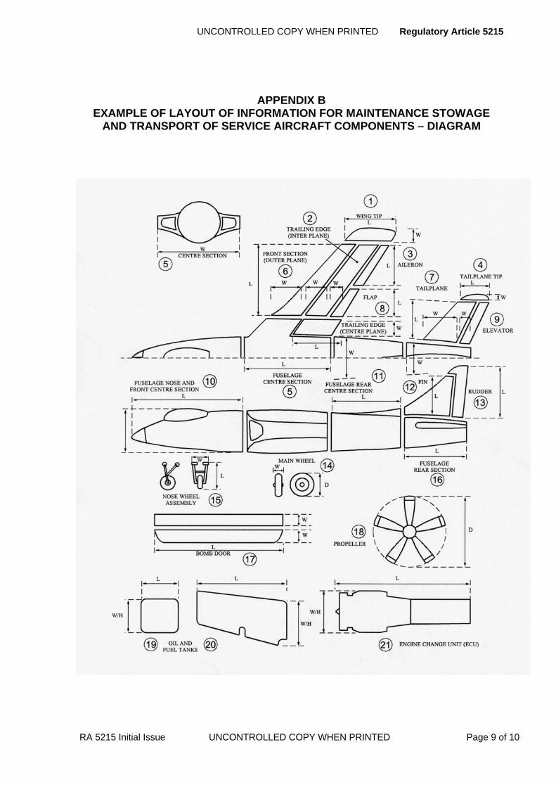
UNCONTROLLED COPY WHEN PRINTED Regulatory Article 5215
RA 5215 Initial Issue UNCONTROLLED COPY WHEN PRINTED Page 9 of 10
APPENDIX B EXAMPLE OF LAYOUT OF INFORMATION FOR MAINTENANCE STOWAGE
AND TRANSPORT OF SERVICE AIRCRAFT COMPONENTS – DIAGRAM

Regulatory Article 5215 UNCONTROLLED COPY WHEN PRINTED
Page 10 of 10 UNCONTROLLED COPY WHEN PRINTED RA 5215 Initial Issue
MASSES AND DIMENSIONS OF COMPONENTS ITEM No. 1 2 3 4 5 6 7 8 9 10 11 12 13 14 15 16 17 18 19 20 21 22 23 24 25 26 LENGTH ‘L’ IN m HEIGHT ‘H’ IN m WIDTH ‘W’ IN m UNPACKAGED MASS kg PACKAGE
STANDARD PACKAGE
MASS kg
RESTRICTED PACKAGE
MAN HOURS FOR DISMANTLING AND ERECTION OF COMPONENTS
COMPONENTS REMOVAL
REFITTING COMPONENT REMOVA
L REFITTING
ENGINE (1, 2, 3 Etc.) TO/FROM MOUNTING FRAME BOMB DOORS TO/FROM FUSELAGE MOUNTING FRAME TO/FROM FUSELAGE OR M/Pl. MAIN UNDERCARRIAGE TO/FROM AIRFRAME REAR PORTION TO/FROM ADJACENT FUSELAGE PORTION OR CENTRE SECTION NOSE OR TAIL OLEO TO/FROM FUSELAGE
FUSELAGE REAR CENTRE PORTION TO/FROM CENTRE SECTION PILOT’S CANOPY TO/FROM FUSELAGE
CENTRE SECTION TO/FROM NOSE AND CENTRE SECTION HYDRAULIC TANK(S) IN/OUT AIRFRAME
TRAILING EDGE CENTRE PLANE TO/FROM CENTRE SECTION ENGINE CHANGE UNIT TO/FROM AIRFRAME
HINGED LEADING EDGE TO/FROM CENTRE SECTION OR MAINPLANE PROPELLER TO/FROM ENGINE CHANGE UNIT
FRONT CENTRE SECTION OUTER PLANE OR MAINPLANE TO/FROM CENTRE SECTION
TRAILING EDGE OUTER PLANE TO/FROM MAINPLANE WING TIP TO/FROM MAINPLANE AILERON TO/FROM MAINPLANE WING TIP TO/FROM MAINPLANE TAILPLANE TO/FROM MAINPLANE FIN TO/FROM FUSELAGE OR TAILPLANE RUDDER TO/FROM FIN TAILPLANE TIP TO/FROM TAILPLANE FUEL TANKS (MAIN, 1, 2, 3, Etc.) IN/OUT AIRFRAME FUEL TANKS (DROP OVERLOAD, Etc.) IN/OUT AIRFRAME
OIL TANKS (1, 2, 3, Etc.) IN/OUT AIRFRAME
AP
PE
ND
IX C
E
XA
MP
LE
LA
YO
UT
OF
INF
OR
MA
TIO
N F
OR
MA
INT
EN
AN
CE
ST
OW
AG
E A
ND
T
RA
NS
PO
RT
OF
SE
RV
ICE A
IRC
RA
FT
CO
MP
ON
EN
TS
DA
TA
SH
EET
UNCONTROLLED COPY WHEN PRINTED Regulatory Article 5216
RA 5216 Initial Issue UNCONTROLLED COPY WHEN PRINTED Page 1 of 2
RA 5216 - Contractor Participation in MOD Flight Testing
Rationale To inform their official assessments, MOD is prepared, in certain cases, to accept the results of contractor’s test flying, and contractor’s technical reports on their flight tests.
Contents 5216(1): Joint Trials
Regulation
5216(1)
Joint Trials 5216(1) The PTL shall decide the details of the joint trials programme
in conjunction with independent specialist advisors and the contractor.
Acceptable Means of Compliance
5216(1)
1. When formulating joint trials programme for a particular aircraft type or variant, the PTL should determine the apportionment of the trials between MOD and the contractor. The contractor should be represented at any discussions.
2. The contractor should declare what is offered for assessment during such trials, and should ensure that MOD and its specialist advisors have access to all relevant information.
3. General approval for a contractor to conduct delegated official flight testing should be granted by inclusion in the DAOS scope certified by MAA to contractors who satisfy the relevant Design Approved Organizations Scheme (DAOS) conditions, (RA 5101 Refers).
4. The DAOS certification should list the broad classes of flight testing which have been authorised and the contractor’s senior personnel associated with that authorisation. Any changes in such personnel, or in the associated organization and facilities relevant to the scope of the authorisation should be reported in writing to MAA.
5. Contractors should submit their proposed test procedures, flight test programmes and methods of analysis to the PTL for agreement prior to the trials.
Guidance Material
5216(1)
6. The details of the joint trials programme do not alter in any way the contractor’s responsibility for safety and functioning tests called for in RA 5217.
7. A contractor or PTL can, at any stage in the development of a new type of aircraft, system or equipment, request a preview evaluation trial, either at the contractor’s site or at any other agreed site whilst the materiel is still on the contractor’s charge. These trials will be under the control of MOD, but the aircraft may remain on the contractor’s charge and be operated to contractor’s procedures. Such trials tend to be of a more qualitative nature, although exceptionally performance measurements are sometimes required at early stages.
8. To save overall calendar time, MOD and contractor joint trials are conducted usually, but not always, at the contractor’s site. These trials are normally carried out on aircraft under the contractor’s control. These trials will often include ground trials, e.g. some of those described in RA 5218, as distinct from flight trials.
9. In some cases MOD may require trials in conditions outside the flight envelope currently achieved by the contractor. Procedures for obtaining the necessary clearance for these trials are given in RA 5202.
Regulatory Article 5216 UNCONTROLLED COPY WHEN PRINTED
Page 2 of 2 UNCONTROLLED COPY WHEN PRINTED RA 5216 Initial Issue
Guidance Material
5216(1)
10. Delegation of MOD flight testing will apply in general only to tests which produce quantitative results. The tests from which contractor’s reports may be accepted will be notified to that contractor and will be reviewed from time to time by MOD.
11. The contractor will seek the prior approval of MAA in respect of his and any subcontractor’s test pilots and airfield facilities, in accordance with the Manual of Flying Orders for Contractors.
12. Approval granted in accordance with this RA may be withdrawn at any time at the discretion of MAA should the circumstances warrant it.
UNCONTROLLED COPY WHEN PRINTED Regulatory Article 5217
RA 5217 Initial Issue UNCONTROLLED COPY WHEN PRINTED Page 1 of 6
RA 5217 - Testing of Pre-Production Aircraft
Rationale This RA describes procedures which are applicable to the testing of pre-production aircraft used in a development programme to establish compliance with the aircraft specification.
Contents 5217(1): Ground Tests
5217(2): Flight Tests
5217(3): Electro-Explosive Device (EED) Tests
Regulation
5217(1)
Ground Tests 5217(1) The contractor shall conduct such ground tests as are
necessary to establish compliance with the aircraft specification.
Acceptable Means of Compliance 5217(1)
1. Given that certain tests are made mandatory in the 5000 Series RAs and in Def Stan 00-970, a schedule of the tests to be made should be prepared by the contractor in conjunction with the Project Team Leader (PTL). 2. All ground tests of the kinds performed in Service should be made as nearly as possible under Service conditions using, wherever possible, the equipment and techniques likely to be used by Service personnel. 3. The contractor should supply, and ordinarily test, specimens of such parts of the aircraft as may be necessary to ensure that the static strength and aeroelastic characteristics of the aircraft will be satisfactory. 4. The contractor should also demonstrate, by calculation and when necessary by fatigue tests, that the fatigue life of the aircraft exceeds the specified life under the loading conditions stated in the aircraft specification. 5. The PTL should be notified of the above tests in advance. Such additional specimens and tests as may be required by MOD to support the assumptions made in the strength and aeroelastic calculations should be provided by the contractor under separate arrangements. 6. When the structural test programme is discussed with the PTL, special attention should be given to any structural problems which are likely to be of general interest to industry. In such instances provision for the necessary research tests should be made, normally under separate arrangements. 7. When it is necessary to fly before the structural tests have been completed, consideration should be given to the hazards involved and the type of flying restricted accordingly. 8. During the tests any significant structural damage that occurs should be reported immediately to the PTL and MAA so that the implications on the safety and serviceability of aircraft in service can be considered and any necessary action can be taken to inform the Services. 9. The contractor should carry out such wind tunnel tests as are necessary to ensure that the aerodynamic characteristics of the aircraft are likely to be satisfactory (see also RA 5216). 10. When it is necessary to fly before the wind tunnel tests have been completed, consideration should be given to the hazards involved and the type of flying restricted accordingly.

Regulatory Article 5217 UNCONTROLLED COPY WHEN PRINTED
Page 2 of 6 UNCONTROLLED COPY WHEN PRINTED RA 5217 Initial Issue
Acceptable Means of Compliance5217(1)
11. The contractor should prepare reports on those ground tests (including tests on working rigs) that need to be included or referred to in the type record and for acceptance of the aircraft (see 5100 Series RAs). Four copies of each report should be issued to the PTL for distribution to the appropriate branches of the MOD and the Service department.
Guidance Material
5217(1)
12. The MOD reserves the right to circulate, for UK Government purposes, data contained in reports of any tests relating to the design of the aircraft that may be undertaken on his behalf.
Regulation
5217(2)
Flight Tests 5217(2) The contractor shall conduct, on aircraft agreed for the
purpose, such flight tests as are necessary to demonstrate the safety and functioning of the aircraft and its installations.
Acceptable Means of Compliance
5217(2)
13. At an early stage in the development of a new type of aircraft the PTL should call a meeting to agree the contractor’s flight test programme (RA 5216).
14. The tests to be made should include those required by Def Stan 00-970 Part 1 Section 2 or Part 7 sections 9 and 10, as appropriate, current at the time and those necessary to verify the suitability, for both normal and emergency use, of the flying clothing and personal equipment specified in the Aircrew Equipment Assembly (AEA) and the associated systems in the aircraft.
15. The contractor should conduct flight tests as soon as possible to establish the performance and handling characteristics of the aircraft, so that the estimates can be checked.
16. A flight test should not be deemed to have been completed until copies of the day-to-day flight test reports called for in para. 26 below have been received by the PTL.
17. For any trial in which there is a risk of departure from controlled flight (e.g. stalling, spinning, investigation of aeroplane behaviour at high incidence, low speed asymmetric flight etc.), the fitment of a device to aid recovery of the trials aeroplane should be considered in accordance with Def Stan 00-970, Part 1, Section 9, Clause 9.7.
18. The contractor should decide what clothing and personal equipment, including emergency equipment, the pilot and other personnel are to wear during flight tests, unless the use of particular articles is specifically stated as a requirement for the test. The contractor should also ensure that any operating limitations which may be imposed by the equipment are not exceeded.
19. Whenever possible, flying should be carried out with the AEAs that are proposed as standard when the aircraft is in Service use. This should apply, in particular, whenever the questions of crew comfort, crew safety, instrument location, control accessibility, angle of vision, etc. need consideration. Test flying should not, however, be held up on account of the non-availability of approved items of equipment; in such instances, the contractor should decide on an appropriate substitute.
UNCONTROLLED COPY WHEN PRINTED Regulatory Article 5217
RA 5217 Initial Issue UNCONTROLLED COPY WHEN PRINTED Page 3 of 6
Acceptable Means of Compliance 5217(2)
20. When aircraft are being flown for the purpose of type trials, whether at a contractor’s works or at a MOD establishment, it is of prime importance that the equipment listed in the AEA schedule for the aircraft should be used. In this case, the use of substitute equipment should require the prior approval of the PTL.
21. Where, for special reasons, the operating limitations of the AEA are likely to be exceeded during any particular flight test programme, the contractor should decide whether to use the AEA or whether suitable substitute equipment should be used.
22. Contractors operating research and other non-standard MOD aircraft for which AEA schedules have not been issued should prepare special assemblies. Care should be taken to ensure that the operating limitations of the resultant assembly permit the flying planned for the aircraft (see paras 32 - 34).
23. Except where it is a specific condition of contract, flight trials of unapproved aircrew equipment should not be combined with the flight testing of MOD aircraft without prior joint agreement of the PTL and the Aircrew Escape Survival (AES) PTL.
24. As far as possible, the normal operational fuel quoted in the aircraft specification should be used during the flight testing of aircraft, except as may be agreed by the PTL or where the use of a particular type of fuel is specified in the flight test requirement.
25. Aircraft for which details of the performance and/or standard of fit are graded ‘restricted’ or above should only show the necessary external markings listed below:
a. Roundels. b. Fin flashes. c. Aircraft serial number. d. Ejection seat warning notices. e. Any special markings required for flight test measurement purposes. f. Warning notices of a general character considered essential by the contractor, provided these do not contain reference to a specific item of equipment.
26. The contractor should prepare, as appropriate:
a. Day-to-day flight test reports.
b. Summaries of the day-to-day flight tests, at suitable intervals dependent on the frequency of flight testing, and in particular after any set phase of the testing has been completed.
c. Reports on particular items or systems or on important areas of development, giving conclusions and recommendations.
d. Reports on any flutter, buffeting or vibration troubles experienced in flight and on any incipient structural failures including, where appropriate, details of the proposed remedial action in each case.
e. A report summarising the results of the flight tests.
f. six copies of day-to-day flight test reports and four copies of the other flight test reports should be supplied to the PTL.
27. The day-to-day flight test report should include:
a. The purpose and duration of the flight.
b. Particulars of the loading conditions, configuration, and any alterations made to the aircraft since it was last flown.
c. A qualitative report by the pilot on the handling qualities of the aircraft, the functioning of systems and installations and any other characteristics, together with the flight observer’s comments, if any.
d. A list of points requiring rectification.

Regulatory Article 5217 UNCONTROLLED COPY WHEN PRINTED
Page 4 of 6 UNCONTROLLED COPY WHEN PRINTED RA 5217 Initial Issue
Acceptable Means of Compliance
5217(2)
28. When quantitative results have been obtained during a flight test these, when corrected for errors and analyzed, should be included in the report unless availability of that data would hold up early issue of the report. In such cases, the quantitative data should be supplied later as an addendum to the report, giving:
a. A list of all instrument records (copies of any of which shall be supplied to the PTL on request).
b. Quantitative results deduced from analysis of the records.
29. A list of flight test reports should be prepared for attachment to the Form 100 for the aircraft (see 5100 Series RAs).
Guidance Material
5217(2)
30. Official flight tests to determine the performance and handling qualities of the aircraft and its general suitability for Service use will normally be made by the MOD, but by arrangement between MOD and the contractor, certain flight trials may be carried out by an integrated team of MOD and contractor’s personnel.
31. Certain quantitative flight tests may be delegated to the contractor under the procedure of RA 5216.
32. The provisioning of the AEAs for the aircraft type will be the responsibility of the PTL.
33. Substitute equipment must be compatible with the aircraft’s normal and emergency supply systems.
34. Advice on available equipment which may be used in substitution may be obtained from the MOD AES PT.
35. For all flying of MOD aircraft not covered by paras 20 - 22 and where the appropriate AEA schedule includes equipment not immediately available, the contractor is authorized to use alternative standard Service issue equipment, provided the flight limitations of the resultant assembly are observed.
36. The attention of contractors is directed to 2000 Series RAs regarding medical fitness, indoctrination in the correct use of aircrew equipment and authorisation for flight within various altitude categories, of all aircrew and others required to fly in MOD aircraft.
37. The general requirements for markings on Service aircraft are given in Def Stan 00-970 Part 1, Section 7.Clause 7.4, and Part 7, Section 1, Leaflet 103.
38. The MOD reserves the right to circulate, for UK Government purposes, data contained in reports of any tests relating to the design of the aircraft that may be undertaken on his behalf.
Regulation
5217(3)
EED Tests 5217(3) Aircraft which embody Electro-Explosive Devices (EED) in
airframe components or equipment installations shall be tested to ensure that a satisfactory level of EMC exists within the aircraft and in any external environment it may encounter in use.
UNCONTROLLED COPY WHEN PRINTED Regulatory Article 5217
RA 5217 Initial Issue UNCONTROLLED COPY WHEN PRINTED Page 5 of 6
Acceptable Means of Compliance
5217(3)
39. Any proposal to alter existing, or introduce new, EED circuits should be referred through the PTL to MAA for approval. The same procedure should be followed in respect of design changes to any other aircraft system which may result in changes to the EMC of any system in which EEDs are fitted. Changes to the operational environment may also affect the EMC clearance and due consideration should be given when the change becomes known.
40. The contractor should ensure that EEDs used in aircraft systems are subject to a characterisation assessment to establish all-fire and no-fire threshold values for energy and power. Characterisation should have been carried out at a designated MOD establishment or by an approved contractor, and full details should be supplied to MAA.
41. EMC tests on individual line replaceable units (LRUs) and test sets should be carried out at a recognised test house to the satisfaction of the PTL.
42. The threshold levels of Radio Frequency (RF) susceptibility should be established for electronic systems used to control the functioning of EEDs.
43. The contractor should provide evidence of the design aspect incorporated to ensure that the test set will operate satisfactorily in an RF environment and will not compromise safety (by increasing EED effective aerial length or by EED sensitization) or correct functioning (by EED dudding) of installed EEDs by its connection and operation. The contractor also should provide a list of possible RF-induced failure modes (i.e. a fault not detected when present) which could, as a consequence, result in a subsequent safety hazard to personnel or equipment.
44. Trials should be conducted to ascertain the EMC of the total aircraft armament system, and contribute to the Release to Service (RTS) recommendations.
Guidance Material
5217(3)
45. The EMC criteria and test levels applicable to EEDs, associated circuits, control equipment and weapon system test sets will be specified by the TAA.

Regulatory Article 5217 UNCONTROLLED COPY WHEN PRINTED
Page 6 of 6 UNCONTROLLED COPY WHEN PRINTED RA 5217 Initial Issue
Intentionally Blank for Print Pagination

UNCONTROLLED COPY WHEN PRINTED Regulatory Article 5218
RA 5218 Initial Issue UNCONTROLLED COPY WHEN PRINTED Page 1 of 4
RA 5218 - Testing of Production Aircraft
Rationale Every new production aircraft to be delivered by a contractor is required to undergo ground and flight tests before delivery which will show the aircraft to be functioning satisfactorily in accordance with the approved test procedures. For aircraft undergoing maintenance, repair or modification, testing is necessary to the extent determined by the statement of work in the contract.
This RA covers the requirements for the preparation of test procedures and the application of tests before delivery of an aircraft.
Contents 5218(1): Ground and Flight Testing
5218(2): Pre-Delivery Testing
Regulation
5218(1) Ground and Flight Testing 5218(1) The Ground Test Procedures and Flight Test Procedures
shall be submitted to the PTL, who will seek comments and recommendations from the appropriate authorities.
Acceptable Means of Compliance
5218(1)
1. The preparation and maintenance of test procedures for new production aircraft should be the responsibility of the aircraft Design Organization (DO).
2. The DO should prepare a draft of ground test procedures comprising:
a. Any relevant production test requirements, which may be contained in Def Stan 00-970 or equivalent design requirements as specified in the contract.
b. Tests selected as appropriate to the aircraft type, taken from ground tests for development aircraft in Def Stan 00-970 or equivalent design requirements as specified in the contract, and adapted for production purposes.
c. Any additional tests necessary for the particular type of aircraft. d. Any percentage tests required. e. Appropriate tests to demonstrate that the aircraft complies with the specification.
3. The DO should prepare a draft of flight test procedures comprising:
a. Pilot’s and, where appropriate, other aircrew pre-flight checks. b. Any special tests necessary for the particular type of aircraft. c. Any percentage test required. d. Tests of the aircraft systems appropriate to the aircraft type. e. Appropriate tests to demonstrate that the aircraft complies with the specification.
4. The draft ground test procedures and flight test procedures should be available three months before they are required for use, unless otherwise specified in the contract.
5. Ground tests and flight tests which will also be carried out by the Services should be specified using wherever possible the equipment and techniques likely to be used by Service personnel.
6. The ground test procedure should specifically identify any test equipment to be used in carrying out the test procedure.
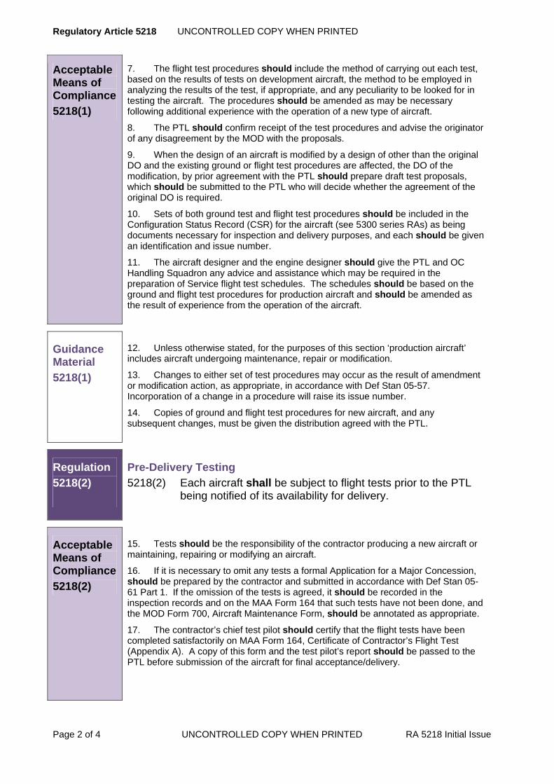
Regulatory Article 5218 UNCONTROLLED COPY WHEN PRINTED
Page 2 of 4 UNCONTROLLED COPY WHEN PRINTED RA 5218 Initial Issue
Acceptable Means of Compliance
5218(1)
7. The flight test procedures should include the method of carrying out each test, based on the results of tests on development aircraft, the method to be employed in analyzing the results of the test, if appropriate, and any peculiarity to be looked for in testing the aircraft. The procedures should be amended as may be necessary following additional experience with the operation of a new type of aircraft.
8. The PTL should confirm receipt of the test procedures and advise the originator of any disagreement by the MOD with the proposals.
9. When the design of an aircraft is modified by a design of other than the original DO and the existing ground or flight test procedures are affected, the DO of the modification, by prior agreement with the PTL should prepare draft test proposals, which should be submitted to the PTL who will decide whether the agreement of the original DO is required.
10. Sets of both ground test and flight test procedures should be included in the Configuration Status Record (CSR) for the aircraft (see 5300 series RAs) as being documents necessary for inspection and delivery purposes, and each should be given an identification and issue number.
11. The aircraft designer and the engine designer should give the PTL and OC Handling Squadron any advice and assistance which may be required in the preparation of Service flight test schedules. The schedules should be based on the ground and flight test procedures for production aircraft and should be amended as the result of experience from the operation of the aircraft.
Guidance Material
5218(1)
12. Unless otherwise stated, for the purposes of this section ‘production aircraft’ includes aircraft undergoing maintenance, repair or modification.
13. Changes to either set of test procedures may occur as the result of amendment or modification action, as appropriate, in accordance with Def Stan 05-57. Incorporation of a change in a procedure will raise its issue number.
14. Copies of ground and flight test procedures for new aircraft, and any subsequent changes, must be given the distribution agreed with the PTL.
Regulation
5218(2)
Pre-Delivery Testing 5218(2) Each aircraft shall be subject to flight tests prior to the PTL
being notified of its availability for delivery.
Acceptable Means of Compliance
5218(2)
15. Tests should be the responsibility of the contractor producing a new aircraft or maintaining, repairing or modifying an aircraft.
16. If it is necessary to omit any tests a formal Application for a Major Concession, should be prepared by the contractor and submitted in accordance with Def Stan 05-61 Part 1. If the omission of the tests is agreed, it should be recorded in the inspection records and on the MAA Form 164 that such tests have not been done, and the MOD Form 700, Aircraft Maintenance Form, should be annotated as appropriate.
17. The contractor’s chief test pilot should certify that the flight tests have been completed satisfactorily on MAA Form 164, Certificate of Contractor’s Flight Test (Appendix A). A copy of this form and the test pilot’s report should be passed to the PTL before submission of the aircraft for final acceptance/delivery.

UNCONTROLLED COPY WHEN PRINTED Regulatory Article 5218
RA 5218 Initial Issue UNCONTROLLED COPY WHEN PRINTED Page 3 of 4
Guidance Material
5218(2)
18. Unless otherwise stated, for the purposes of this section ‘production aircraft’ includes aircraft undergoing maintenance, repair or modification.
19. The tests are to be conducted in accordance with the ground test procedures and may be subject to surveillance by the PTL.
20. Additional tests may be required on a proportion of aircraft delivered; details will be agreed between the appropriate designer and the PTL.
21. Any such additional tests must be recorded on the MAA Form 164, which must be reproduced locally using Appendix A as a template.

Regulatory Article 5218 UNCONTROLLED COPY WHEN PRINTED
Page 4 of 4 UNCONTROLLED COPY WHEN PRINTED RA 5218 Initial Issue
APPENDIX A CERTIFICATE OF CONTRACTOR'S FLIGHT TEST
Contract No………………………..Aircraft (Type)……………………Service No……………
Name of Pilot(s)………………………………………………………………………………….
…………………………………………………………………………………………………….
Date of Flight(s)…………………………………………………………………………………..
…………………………………………………………………………………………………….
Duration of Flight(s)……………………………………………………………………………...
Certified that the above aircraft has been flight tested in compliance with the conditions of the contract (exceptions as covered by amendment to contract/Application Major Concession), that the functioning tests and observations etc., detailed in Flight Test Procedure(s) as specified below were satisfied, and that the aircraft was proved on the ground and in the air in all respects.
Flight Test Procedure(s)*
Signed…………………..……for and on behalf of…………………………… Name……………………………………………….. Chief Test Pilot ……………………………..
Date……………………...……...
*Insert as appropriate
MAA FORM 164

UNCONTROLLED COPY WHEN PRINTED Regulatory Article 5219
►This RA has been substantially re-written; for clarity no change marks are presented - please read RA in entirety◄
RA 5219 - Instrumentation and Accident Data Recorder Requirements for Flight Tests of Aircraft
Rationale Instrumentation is required for Contractors’ and official flight tests of new types of aircraft, and of aircraft incorporating major modifications. The installation of an Accident Data Recorder (ADR) may also be required.
Contents 5219(1): Instrumentation and ADR Requirements
5219(2): Accident Data Recorder (ADR) for Flight Trials - Withdrawn - Incorporated into RA5219(1)
5219(3): Identification of Instrumentation
Regulation
5219(1)
Instrumentation and ADR1 Requirements 5219(1) As soon as possible after the flight test programme has been
agreed, the Type Airworthiness Authority (TAA) shall consider the need for installation of instrumentation and Accident Data Recorder (ADR) for the purposes of the flight test programme, in consultation with the Contractor.
Acceptable Means of Compliance
5219(1)
Instrumentation and ADR Requirements 1. The instrumentation and ADR requirements, including the parameters to be measured, should be formally recorded
2. The following requirements should be considered:
a. Instrumentation required in each aircraft allocated for flight trials.
b. Provision for automatic monitoring and recording.
c. Provision for navigational or safety aids necessary for the safe, speedy and satisfactory conduct of the flight trials.
d. Provision of ADR for:
(1) Trials of major modifications.
(2) Trials which seek to extend the approved flight limitations or which entail an extra-to-normal hazard.
(3) Trials of any special equipment installation which might affect the safety of the aircraft.
3. The instrumentation methods, standards and the installation should meet the requirements of the MOD establishment primarily concerned with the trials. All installations should conform to the airworthiness and strength requirements applicable to the aircraft concerned, or by agreement with the TAA to the requirements of Def Stan 00-970.
4. The Contractor should submit all relevant information on the instrumentation to the TAA.
5. The instrumentation drawings should be included in the Configuration Status Record (CSR) or equivalent drawing list for the aircraft.
6. The Contractor should demonstrate to the satisfaction of the TAA, with appropriate tests and safety arguments, that the installation, when completed, is safe and effective.
RA 5219 Issue 2 UNCONTROLLED COPY WHEN PRINTED Page 1 of 2
1 The term ADR utilized in this RA may also be taken to read Flight Data Recorder (FDR).
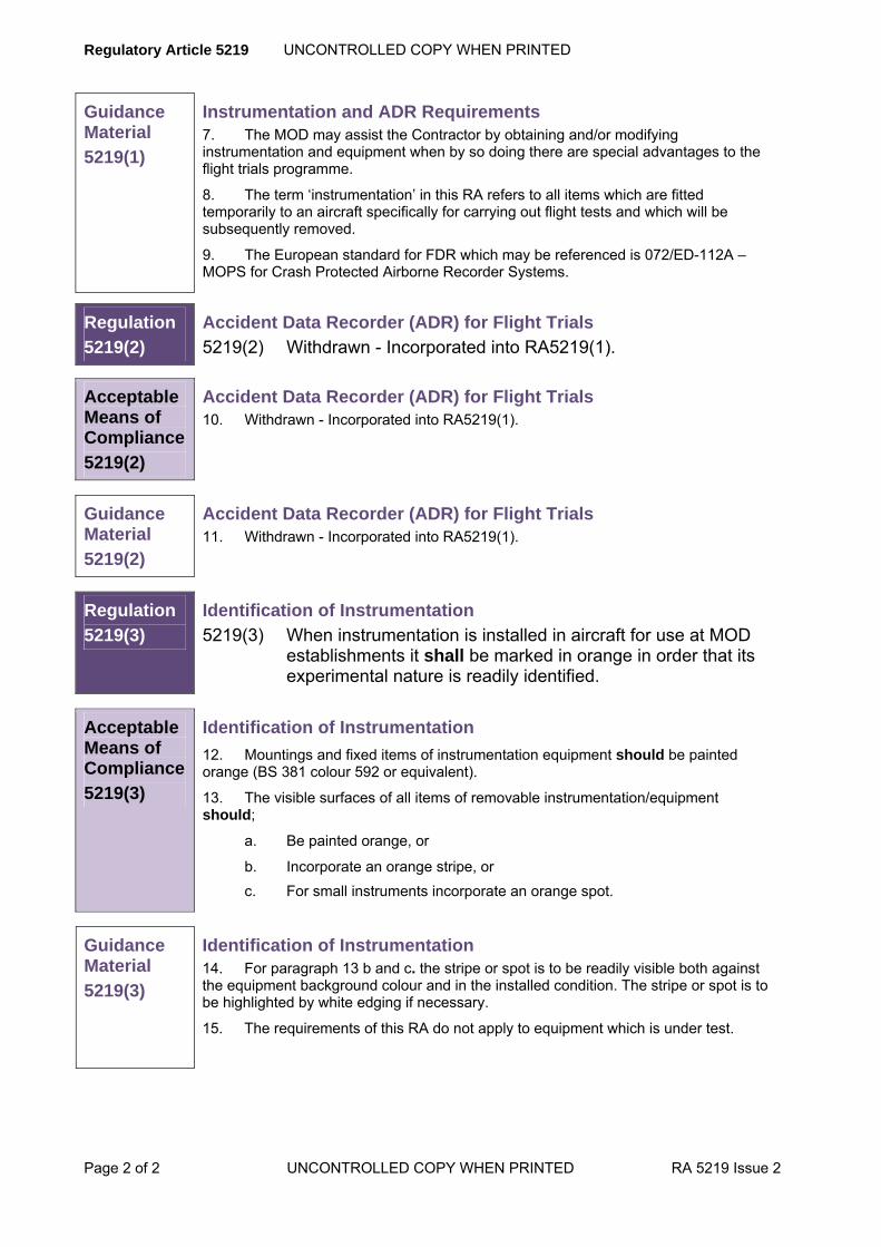
Regulatory Article 5219 UNCONTROLLED COPY WHEN PRINTED
Page 2 of 2 UNCONTROLLED COPY WHEN PRINTED RA 5219 Issue 2
Guidance Material
5219(1)
Instrumentation and ADR Requirements 7. The MOD may assist the Contractor by obtaining and/or modifying instrumentation and equipment when by so doing there are special advantages to the flight trials programme.
8. The term ‘instrumentation’ in this RA refers to all items which are fitted temporarily to an aircraft specifically for carrying out flight tests and which will be subsequently removed.
9. The European standard for FDR which may be referenced is 072/ED-112A – MOPS for Crash Protected Airborne Recorder Systems.
Regulation
5219(2)
Accident Data Recorder (ADR) for Flight Trials 5219(2) Withdrawn - Incorporated into RA5219(1).
Acceptable Means of Compliance
5219(2)
Accident Data Recorder (ADR) for Flight Trials 10. Withdrawn - Incorporated into RA5219(1).
Guidance Material
5219(2)
Accident Data Recorder (ADR) for Flight Trials 11. Withdrawn - Incorporated into RA5219(1).
Regulation
5219(3)
Identification of Instrumentation 5219(3) When instrumentation is installed in aircraft for use at MOD
establishments it shall be marked in orange in order that its experimental nature is readily identified.
Acceptable Means of Compliance
5219(3)
Identification of Instrumentation
12. Mountings and fixed items of instrumentation equipment should be painted orange (BS 381 colour 592 or equivalent).
13. The visible surfaces of all items of removable instrumentation/equipment should;
a. Be painted orange, or
b. Incorporate an orange stripe, or
c. For small instruments incorporate an orange spot.
Guidance Material
5219(3)
Identification of Instrumentation 14. For paragraph 13 b and c. the stripe or spot is to be readily visible both against the equipment background colour and in the installed condition. The stripe or spot is to be highlighted by white edging if necessary.
15. The requirements of this RA do not apply to equipment which is under test.

UNCONTROLLED COPY WHEN PRINTED Regulatory Article 5220
RA 5220 Initial Issue AIL 1 UNCONTROLLED COPY WHEN PRINTED Page 1 of 2
RA 5220 - Special Flying Instructions and Restrictions on Flying
Rationale This RA details the procedures for further restricting the flying limitations or operational roles of military registered aircraft.
Contents 5220(1): Issue of SFI in the Development Environment
5220(2): Responsibilities of Contractors
Regulation
5220(1)
Issue of SFI in the Development Environment 5220(1) Restrictions on the flying limitations for development flights shall be prepared by the Chief Designer and subsequently approved by the PTL.
Acceptable Means of Compliance
5220(1)
1. To facilitate the timely promulgation of restrictions on flying limitations for Contractors’ and Service pilots, out with the MFTP approval process, the PTL should issue the SFI on advice from a competent organization (e.g. the Aircraft DO).
2. The SFI should be more restrictive than the original clearance .
3. It is of vital importance to aircraft safety that, on any matter which could involve a restriction on published flying limitations, there should be a rapid exchange of information between all operators of a particular aircraft type and, where appropriate, type derivatives.
Guidance Material
5220(1)
4. The need to apply a restriction usually stems from consideration of a serious fault, incident, or accident and urgent action may be needed to cover the period during which the cause is being ascertained.
5. Information indicating a need for the issue of a restriction may emanate from:
a. Independent Technical Evaluator.
b. The contractor.
c. Any responsible Aviation Duty Holder.
d. Civil operators.
e. Commonwealth or foreign military services.
6. The issue of a restriction on a particular aircraft type may necessitate the issue of similar restrictions on other types with similar characteristics, equipment or engines.
Regulation
5220(2)
Responsibilities of Contractors 5220(2) The contractor shall notify the PTL of evidence, from any
source, which could indicate a need for a restriction on flying or the issue of a restrictive SFI for any Service aircraft.

Regulatory Article 5220 UNCONTROLLED COPY WHEN PRINTED
Page 2 of 2 UNCONTROLLED COPY WHEN PRINTED RA 5220 Initial Issue AIL 1
Acceptable Means of Compliance
5220(2)
7. The contractor should make arrangements with the PTL to ensure that he is advised immediately at any time - if necessary by telephone - of any proposals or decisions concerning the application of a restriction.
8. On receiving, from the contractor, any proposals or decisions concerning the application of a restriction the PTL should then inform the RTSA, MAA, OC Handling Squadron and the Operational Duty Holder, as appropriate .
Guidance Material
5220(2)
9. The contractor will be advised by the PTL of any evidence from MOD sources or elsewhere, which might justify a change in flying limitations.
10. Restrictions on flying limitations or restrictive SFIs are normally applicable to all aircraft of the MOD Air Fleet. It is possible, however, that an SFI may not be applicable to a particular aircraft, e.g. one engaged on trials to investigate the reasons for the restriction and to seek a solution; in such cases a concession will be granted by the PTL.
11. For aircraft types not released for Service use, the issue of restrictions as detailed in RA 5220(1) will normally involve discussions between the contractor and PT staff.
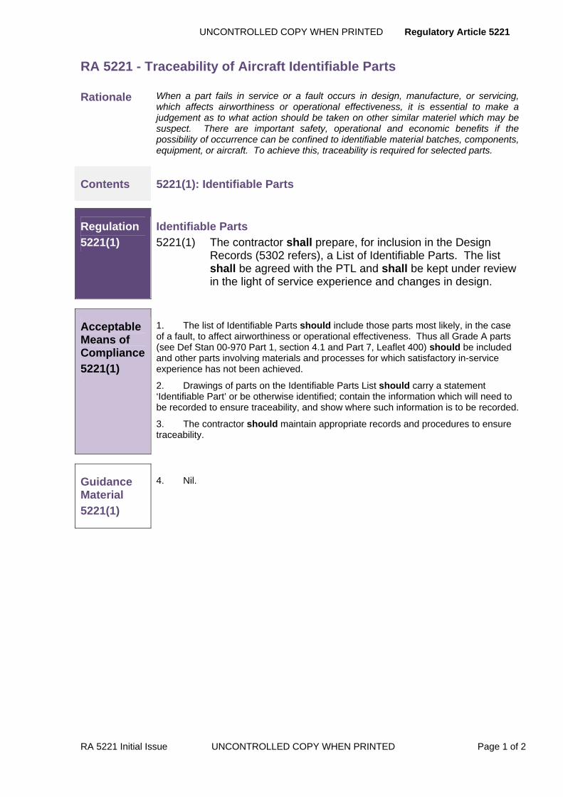
UNCONTROLLED COPY WHEN PRINTED Regulatory Article 5221
RA 5221 Initial Issue UNCONTROLLED COPY WHEN PRINTED Page 1 of 2
RA 5221 - Traceability of Aircraft Identifiable Parts
Rationale When a part fails in service or a fault occurs in design, manufacture, or servicing, which affects airworthiness or operational effectiveness, it is essential to make a judgement as to what action should be taken on other similar materiel which may be suspect. There are important safety, operational and economic benefits if the possibility of occurrence can be confined to identifiable material batches, components, equipment, or aircraft. To achieve this, traceability is required for selected parts.
Contents 5221(1): Identifiable Parts
Regulation
5221(1)
Identifiable Parts 5221(1) The contractor shall prepare, for inclusion in the Design
Records (5302 refers), a List of Identifiable Parts. The list shall be agreed with the PTL and shall be kept under review in the light of service experience and changes in design.
Acceptable Means of Compliance 5221(1)
1. The list of Identifiable Parts should include those parts most likely, in the case of a fault, to affect airworthiness or operational effectiveness. Thus all Grade A parts (see Def Stan 00-970 Part 1, section 4.1 and Part 7, Leaflet 400) should be included and other parts involving materials and processes for which satisfactory in-service experience has not been achieved.
2. Drawings of parts on the Identifiable Parts List should carry a statement ‘Identifiable Part’ or be otherwise identified; contain the information which will need to be recorded to ensure traceability, and show where such information is to be recorded.
3. The contractor should maintain appropriate records and procedures to ensure traceability.
Guidance Material
5221(1)
4. Nil.

Regulatory Article UNCONTROLLED COPY WHEN PRINTED
Page 2 of 2 UNCONTROLLED COPY WHEN PRINTED RA Initial Issue
Intentionally Blank for Print Pagination
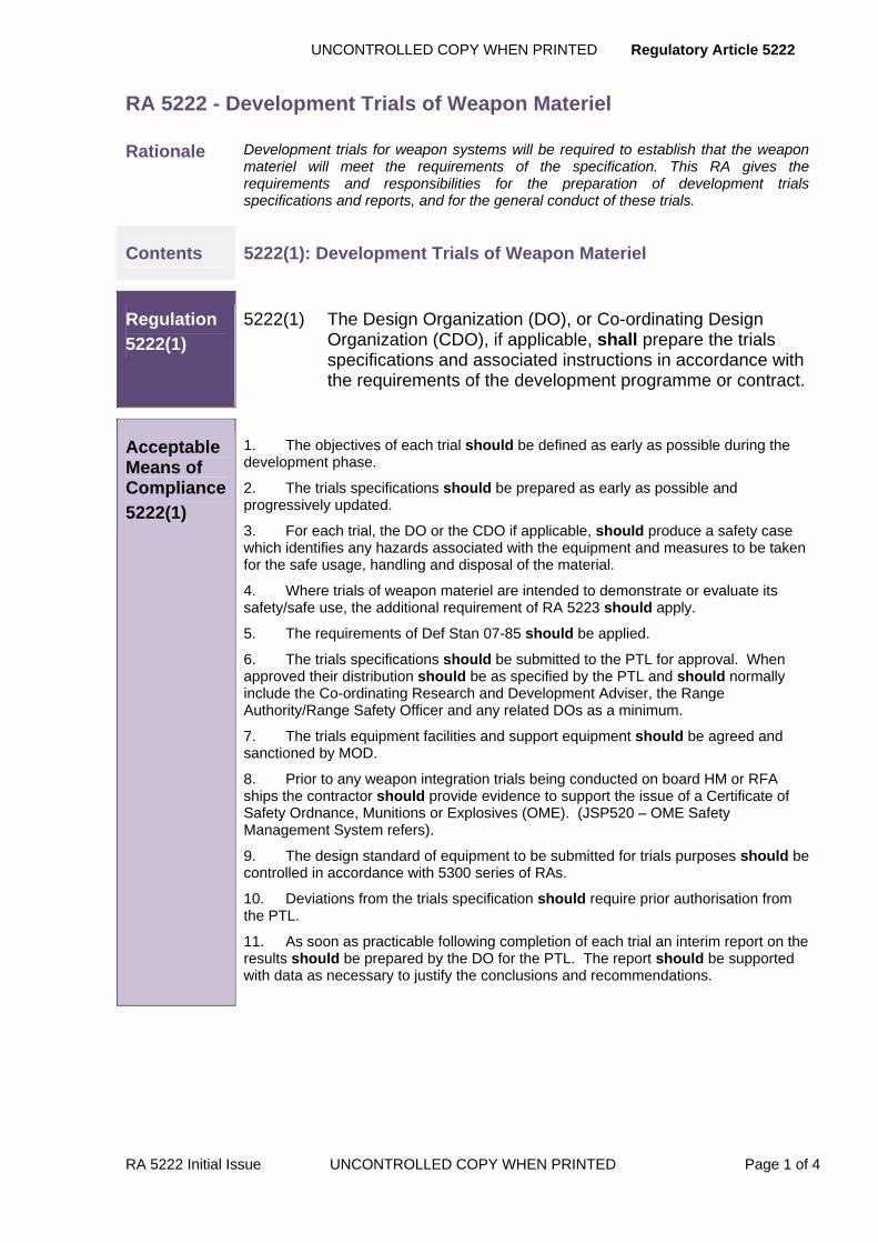
UNCONTROLLED COPY WHEN PRINTED Regulatory Article 5222
RA 5222 Initial Issue UNCONTROLLED COPY WHEN PRINTED Page 1 of 4
RA 5222 - Development Trials of Weapon Materiel
Rationale Development trials for weapon systems will be required to establish that the weapon materiel will meet the requirements of the specification. This RA gives the requirements and responsibilities for the preparation of development trials specifications and reports, and for the general conduct of these trials.
Contents 5222(1): Development Trials of Weapon Materiel
Regulation
5222(1)
5222(1) The Design Organization (DO), or Co-ordinating Design Organization (CDO), if applicable, shall prepare the trials specifications and associated instructions in accordance with the requirements of the development programme or contract.
Acceptable Means of Compliance
5222(1)
1. The objectives of each trial should be defined as early as possible during the development phase.
2. The trials specifications should be prepared as early as possible and progressively updated.
3. For each trial, the DO or the CDO if applicable, should produce a safety case which identifies any hazards associated with the equipment and measures to be taken for the safe usage, handling and disposal of the material.
4. Where trials of weapon materiel are intended to demonstrate or evaluate its safety/safe use, the additional requirement of RA 5223 should apply.
5. The requirements of Def Stan 07-85 should be applied.
6. The trials specifications should be submitted to the PTL for approval. When approved their distribution should be as specified by the PTL and should normally include the Co-ordinating Research and Development Adviser, the Range Authority/Range Safety Officer and any related DOs as a minimum.
7. The trials equipment facilities and support equipment should be agreed and sanctioned by MOD.
8. Prior to any weapon integration trials being conducted on board HM or RFA ships the contractor should provide evidence to support the issue of a Certificate of Safety Ordnance, Munitions or Explosives (OME). (JSP520 – OME Safety Management System refers).
9. The design standard of equipment to be submitted for trials purposes should be controlled in accordance with 5300 series of RAs.
10. Deviations from the trials specification should require prior authorisation from the PTL.
11. As soon as practicable following completion of each trial an interim report on the results should be prepared by the DO for the PTL. The report should be supported with data as necessary to justify the conclusions and recommendations.

Regulatory Article 5222 UNCONTROLLED COPY WHEN PRINTED
Page 2 of 4 UNCONTROLLED COPY WHEN PRINTED RA 5222 Initial Issue
Guidance Material
5222(1)
12. There is no standard format for trials specifications; trial specifications must include information under all appropriate headings from the list at Appendix A, together with such additional data defined by the DO.
13. The requirements for and purpose of each trial defined in the trials specification must be discussed as early as practicable with the PTL, the trials unit and Range Authority/Range Safety Officer for long term planning of range resources and loading.
14. These trials are carried out by the contractor in which qualitative and quantitative assessments are made of some or all of the characteristics of the weapon materiel being tested, under conditions either actual or simulating those likely to be met in Service.
15. The level of support required from the contractor in aid of all these trials will be specified by the PTL.
16. Trials may take place:
a. At the premises of the DO or at an approved test house.
b. At MOD facilities such as a trials establishment or range at which the DO will be represented.
c. At a Service unit (ashore or afloat); the DO providing the equipment-under-test for the trials.
d. At trials sites provided by a contractor.
17. Responsibility for the conduct of each trial will rest with the trials unit. The regulations and requirements in force at MOD establishments, Service units or test houses must be complied with.
18. The safety requirements to be met for trials carried out in HM ships and Royal Navy establishments are laid down in BR 862 ‘NAVAL EXPLOSIVE REGULATIONS’ Chapter 10.
19. The DO is responsible for ensuring that the build standard of equipment submitted for trials conforms to the design standard stated in trials specifications.
20. The DO, or CDO, if applicable, is responsible for specifying the requirement for the recording and reporting of Data by the trials unit. The DO is also responsible for collating all relevant information and submitting this in the form of a final report for the PTL. Where trials are carried out entirely by a Service unit, the unit will be responsible for supplying the DO with all relevant data.
21. The circulation for each report will be to the requirements of the PTL.

UNCONTROLLED COPY WHEN PRINTED Regulatory Article 5222
RA 5222 Initial Issue UNCONTROLLED COPY WHEN PRINTED Page 3 of 4
APPENDIX A REQUIREMENTS FOR TRIALS SPECIFICATIONS
A.1 Introduction - Title of equipment and trial
A.1.1 Equipment.
A.1.2 Purpose.
A.1.3 Background information.
A.1.4 Location.
A.1.5 Dates.
A.1.6 Quantities.
A.1.7 Design standard.
A.2 Contractual/Administrative data
A.2.1 Contract number.
A.2.2 DO or Co-ordinating DO.
A.2.3 Weapon Safety Officer(s).
A.2.4 Range Safety Officer(s).
A.2.5 Personnel with responsibility for trials preparation or provision of specialist equipment.
A.2.6 Other relevant names and addresses.
A.3 Objective
A.3.1 Full details of parameters to be examined.
A.3.2 Environmental conditions or restrictions.
A.3.3 Specialist equipment and installation details.
A.3.4 Details of launch platform as appropriate.
A.4 Instrumentation and Targets
A.4.1 Targets.
A.4.2 Telemetry.
A.4.3 Instrumentation.
A.4.4 Tracking facilities.
Regulatory Article 5222 UNCONTROLLED COPY WHEN PRINTED
Page 4 of 4 UNCONTROLLED COPY WHEN PRINTED RA 5222 Initial Issue
A.5 Safety
A.5.1 Advice on potential hazards.
A.5.2 Disposal of stores.
A.5.3 Handling.
A.5.4 Safety aspects to be included in procedures.
A.6 Security Classification
A.6.1 Equipment.
A.6.2 Information.
A.6.3 Report.

UNCONTROLLED COPY WHEN PRINTED Regulatory Article 5223
RA 5223 Initial Issue UNCONTROLLED COPY WHEN PRINTED Page 1 of 2
RA 5223 - Trials to Assess the Safety of Weapons Materiel
Rationale Trials are required to demonstrate that, during all phases of Service life, equipment is safe to assemble, disassemble, inspect, test, transport, store, maintain and use. This RA defines the procedure to be followed for trials to assess the safety of a weapon system or subsystem.
Contents 5223(1): Trials to Assess the Safety of Weapons Materiel
Regulation
5223(1)
Trials to Assess the Safety of Weapons Materiel 5223(1) As early as possible during the development phase the
Design Organization (DO), or Co-ordinating DO(CDO) if applicable, shall consider the system and subsystem to determine those parts which are potentially hazardous and may affect the safety of the system and shall define trials necessary to demonstrate that the weapon equipment is safe during all stages of use.
Acceptable Means of Compliance
5223(1)
1. This RA should be read in conjunction with RA 5222, the requirements of which apply.
2. The trials should also include non-hazardous parts which may influence the safe operation of the system.
3. The DO should identify all circumstances, including environmental conditions, likely to influence the safe operation of those parts of the system or subsystem which are potentially hazardous.
4. Such trials as are required to demonstrate that the weapon equipment is safe during the stages of use identified in this RA should be defined in a trials specification by the DO if applicable. The trials specification should be prepared in accordance with RA 5222.
5. The trials specification should be submitted by the DO to the PTL for approval, and then distributed in accordance with their requirements.
6. The conduct of trials and reporting of results should be carried out in accordance with RA 5222.
Guidance Material
5223(1)
7. The trials must demonstrate that, during all phases of Service life, the equipment is safe to assemble, disassemble, inspect, test, transport, store, maintain and use.
8. The contractor/DO, through the PTL, will consult with the Defence Ordnance Safety Group (DOSG) on the requirements for development trials.

Regulatory Article UNCONTROLLED COPY WHEN PRINTED
Page 2 of 2 UNCONTROLLED COPY WHEN PRINTED RA Initial Issue
Intentionally Blank for Print Pagination

UNCONTROLLED COPY WHEN PRINTED Regulatory Article 5301
RA 5301 Initial Issue UNCONTROLLED COPY WHEN PRINTED Page 1 of 2
RA 5301 - Control of Designs
Rationale A project’s design must be controlled from the perspective of configuration control and maintenance of design records in order to ensure a smooth lead-in to the certification of design.
Contents 5301(1): Configuration Management of Design
5301(2): Management of Design Records
Regulation
5301(1)
Configuration Management of Design 5301(1) The Design Organization (DO) shall control the design in
accordance with an agreed Configuration Management Plan (CMP).
Acceptable Means of Compliance
5301(1)
1. A Configuration Management Plan (CMP) should be prepared in accordance with the requirements of DefStan 05-57; Configuration Management of Defence Materiel.
2. The CMP should be agreed with the PTL at the commencement of the contract and should be subject to review and revision at regular intervals as the design progresses.
3. The CMP forms part of the design records and should be maintained throughout the product lifespan.
4. Within the CMP the DO should establish a committee which shall bring under its control all sufficiently stable designs. This committee should:
a. Prepare and maintain a provisional configuration status record (CSR).
b. Control design changes.
c. Record and control the standard of design to be manufactured.
d. Record the reasons for its decisions.
e. Make available to the PTL the record of its decisions.
5. The PTL and the DO, if not the contractor, should be invited to committee meetings at which the difficulties in meeting the contract or proposals to bring designs Under Ministry Control (UMC) are to be discussed.
6. When the design is brought UMC, the PTL should establish a committee for controlling the design and the contractor should issue a CSR.
7. After the design is brought UMC the design records should be changed in accordance with the procedures described in the agreed CMP and should require that the PTL authorize any change.
Guidance Material
5301(1)
8. During development and before designs are brought UMC, the DO is free to alter the design, within the constraints of the specification.
9. The bringing of the design UMC does not necessarily mean that materiel produced to the design records fully meets the specification.
10. Design processes are progressive so that at any given time the design records
Regulatory Article 5301 UNCONTROLLED COPY WHEN PRINTED
Page 2 of 2 UNCONTROLLED COPY WHEN PRINTED RA 5301 Initial Issue
for a project may not all be at the same stage.
Regulation
5301(2)
Management of Design Records 5301(2) The DO shall ensure that adequate records of design and
development are maintained throughout the life of the project.
Acceptable Means of Compliance
5301(2)
11. The DO should maintain adequate records of design and development; e.g. actions undertaken, design notebooks and diaries, items manufactured or purchased, procedures for and the results of tests and trials.
12. The DO should provide a development programme, the contents of which will be defined or referenced in the contract.
13. At agreed points specified in the development programme these design records should be used as the basis of formal reports to be independently checked and certified by contractor's staff.
14. For materiel used for contractor’s tests and trials, the design check should include confirmation that the materiel is consistent with the quoted design records.
Guidance Material
5301(2)
15. The DO is responsible for the design of equipment to meet the specification based on a development programme, within the constraints imposed by the contract and statutory obligations.
16. As development proceeds, formal control (FC) of the design may be required as a lead-in to the process of bringing the design UMC. It may also be required when long lead-time items need to be ordered. FC will normally be progressive as each group of designs becomes sufficiently stable.
17. Further development leads up to the stage when the design is sufficiently proven that it is considered necessary by the PTL that the design be brought UMC.
18. The certification of design point is reached when the PTL, the contractor and the DO (if the DO is not the contractor) agree that the design of the materiel adequately meets the requirements of the specification within the limits and exceptions stated. Certification of design is dealt with in the 5100 series RAs.
UNCONTROLLED COPY WHEN PRINTED Regulatory Article 5302
RA 5302 Issue 2 UNCONTROLLED COPY WHEN PRINTED Page 1 of 2
RA 5302 - Design Records
Rationale Design records are required to define the standard of design of materiel procured by the MOD. This RA gives the requirements and responsibilities for the supply, custody, maintenance, reproduction and disposal of design records.
Contents 5302 (1): Custody and Maintenance of Design Records
Regulation
5302(1)
Custody and Maintenance of Design Records 5302(1) The Contractor shall maintain at his works a complete set of
drawings, specifications and manufacturing data relating to the Articles supplied and the work performed under the Contract.
Acceptable Means of Compliance
5302(1)
1. During the continuance of the Contract and for a period of not less than two years after its completion the Contractor should maintain at his works at least one complete set of drawings, specifications and manufacturing data relating to the Articles supplied or the work performed under the Contract.
2. When the PTL requires copies of particular drawings the contractor should supply them in accordance with DefStan 05-10.
3. The master set of any such drawings maintained as provided by this clause should not be altered by the Contractor before the expiration of the said period except on the written instructions or with the written permission of the MOD.
4. The MOD should be entitled from time to time, by notice in writing to the Contractor, to require the Contractor to supply to the MOD one or more complete sets or one or more parts of a complete set of such of the following relating to the articles supplied under the contract or of any parts of any such articles or of any other work performed under the contract as may be specified in the notice:
a. Print drawings.
b. Master tracings.
c. Copies of specifications and/or manufacturing data.
5. Master tracings supplied as aforesaid should be on linen cloth or on some alternative material from which reproductions can be made as the MOD may specify in the notice given under sub-paragraph of this paragraph, and all such tracings should be fully dimensioned and should state the permissible manufacturing tolerances, the material finish, and such other particulars as the MOD may specify in the said notice.
6. All prints, tracings and copies of specifications and data should be supplied to the satisfaction of the MOD within the period specified in the said notice.
7. A fair and reasonable price, based on the actual work involved in their preparation, should be paid to the Contractor by the MOD for all prints, tracings and copies of specifications and manufacturing data supplied to the MOD under the provisions of this paragraph.
8. The requirement for the Contractor to supply prints, tracings and copies of specifications and manufacturing data should be exercisable:
a. In relation to all drawings, specifications and manufacturing data at any time before the expiration of the period of two years after the completion of the Contract; and

Regulatory Article 5302 UNCONTROLLED COPY WHEN PRINTED
Page 2 of 2 UNCONTROLLED COPY WHEN PRINTED RA 5302 Issue 2
Acceptable Means of Compliance
5302(1)
b. In relation to any of the said drawings, specifications and manufacturing data which are actually maintained by the Contractor after the expiration of the said period, so long as the same are so maintained.
9. The MOD should be entitled at any time to make copies of any prints, tracings, specifications or manufacturing data supplied under this Condition, as the MOD may think fit and to use such prints, tracings, specifications and manufacturing data (or copies of them) in any UK Government Department, Establishment or Depot and such use should not, unless otherwise provided for in the Contract, extend to the use for tendering or manufacturing purposes.
10. In addition contractors and sub-contractors concerned should retain custody of and safeguard design records until MOD agrees that they may be destroyed. Requests for permission to destroy design records should be made to the PTL.
Guidance Material
5302(1)
11. Where the term drawing is used it will be taken to include drawings and also any associated data, including data retained in a computer system, which defines a product for manufacturing or test purposes.
12. When so provided for in a particular contract, a contractor may be required to supply for United Kingdom Government purposes, copies of the records of an item to any stated standard of design and at any issue standard.

UNCONTROLLED COPY WHEN PRINTED Regulatory Article 5303
RA Initial Issue UNCONTROLLED COPY WHEN PRINTED Page 1 of 4
RA 5303 - Local Technical Committee
Rationale The purpose of a local technical committee (LTC) is to provide a forum for dealing with technical and associated matters, to take decisions and, where the decision would exceed the delegated powers, make recommendations to the PTL or to the Configuration Control Board (CCB), as appropriate. This RA gives the constitution and responsibilities of a local technical committee.
Contents 5303(1): LTC Authority
5303(2): LTC Administration
5303(3): Significant Design Changes
Regulation
5303(1)
LTC Authority 5303(1) A Local Technical Committee (LTC) shall be established on
the written authority of the PTL prior to design records being brought Under Ministry Control (UMC).
Acceptable Means of Compliance
5303(1)
LTC Authority 1. An LTC should consist of four permanent members each of whom should have executive authority:
a. PTL (chairman).
b. PT quality officer.
c. Contractor’s design representative.
d. Contractor’s production representative.
2. When modifications are to be discussed a representative of the Service user should be invited to attend. However, decisions taken by the LTC are not dependent on his attendance except for Guided Weapon (GW) systems where modifications involving retrospective application should not be authorized in the absence of the Service representative.
3. At all meetings of an LTC the permanent members, or deputies fully empowered to act on their behalf, should be present.
LTC for Engines and Associated Equipment 4. Where operational necessity precludes the MOD from implementing the Finite and Non-Finite Life for engines, the LTC should, where possible, provide an assessment of the increased risk associated with operating beyond that life.
5. The Finite and Non-Finite Life to be recognised by the LTC should be stated in terms of cycles or other alternatives as required. The LTC should recommend to the Services the factors to be applied when converting the lives quoted to other indirect parameters such as flying hours, sorties, starts etc.
Guidance Material
5303(1)
LTC Authority 6. An LTC is the committee through which the design records are brought UMC.
7. Although the greater part of the activity of an LTC is devoted to modifications it

Regulatory Article 5303 UNCONTROLLED COPY WHEN PRINTED
Page 2 of 4 UNCONTROLLED COPY WHEN PRINTED RA Initial Issue
Guidance Material
5303(1)
is not intended that it be limited to such work but can also officiate as a means of resolving or referring to MOD local questions which may arise in the implementation of specified technical requirements. An LTC is not concerned with experimental and design matters not involving production nor with production matters not involving design.
8. An LTC may deal with a range of equipment at a contractor, or more than one LTC may be established at a contractor to deal with different types of equipment. The range of each LTC will be detailed in the letter of authority setting up the LTC.
9. Additional representatives of the PTL, Service departments or contractors may be co-opted to give specialist advice, with the prior agreement of the chairman.
10. The letter from the PTL will define the membership and terms of reference of the LTC. In general, the terms of reference will include the following:
a. To assess technically the desirability of each proposal and to consider whether the estimated cost, effort and time justifies modification action.
b. To authorize within prescribed financial or other limits, or recommend to the appropriate Configuration Control Board (CCB), the preparation of modifications and, as may be required, the carrying out of trial installations and ground and flight testing.
c. Make recommendations to the CCB regarding the application and classification of modifications.
d. To monitor modification requirements and progress.
e. To resolve all questions which arise on the build standard control of equipment that is UMC.
LTC for Engines and Associated Equipment 11. The following gives examples of additional subjects which may fall within the scope of the Engine and Associated Equipment LTC and require discussion:
a. Quality/Inspection Matters. Such as Inspection Procedures and Instructions, New and Reconditioning Acceptance Standards, endorsement of Overhaul Instructions required by Def Stan 28-8.
b. Service Life. Recognition of Finite and Non-Finite Lives of components calculated by the Design Contractor, based upon:
(1) Theoretical analysis.
(2) Bench and rig testing.
(3) Overhaul, service and defect experience.
(4) Def Stan 00-970 Pt 11.
c. Relaxation of Acceptance Testing. Granting or withdrawal of relaxation of stripping and testing.
d. Quality Verification Tests. Ratification of results, and resulting actions from QVT.
e. Fault Investigation. Any matters arising as a result of Fault Investigation which come within the scope of the Committee should be reported to the LTC.
f. Service Trial Installations. The review of special features installed in service aircraft for evaluation under the Special Order Only modification classification procedure, the monitoring and subsequent recommendations.

UNCONTROLLED COPY WHEN PRINTED Regulatory Article 5303
RA Initial Issue UNCONTROLLED COPY WHEN PRINTED Page 3 of 4
Regulation
5303(2)
LTC Administration 5303(2) The proceedings of the LTC shall be recorded in narrative
minutes, to which shall be appended the Modification Proposal Forms (MPF) relevant to the business of the meeting.
Acceptable Means of Compliance
5303(2)
12. The LTC should report in the narrative minutes any significant changes in the information given on a MPF.
13. The minutes should be circulated on the authority of the LTC chairman. There should be a minimum external distribution to the following:
a. The chairman, secretary and all permanent members of the relevant CCB if appropriate.
b. The PT contracts officer.
c. The MOD Pricing and Forecasting Group officer (also agenda).
14. When a modification proposal, agreed by an LTC for submission to a CCB, affects in any way materiel supplied by other contractors, notification should be given at an early stage to all concerned (i.e. by circulation of the relevant Modification proposal) to ensure that complementary action is considered.
15. When matters are discussed which concern materiel at another contractor, the LTC should consult the relevant PTL.
Guidance Material
5303(2)
16. If unanimous agreement is not reached, the committee may make a recommendation with a rider giving details of any objections that were raised.
Regulation
5303(3)
Significant Design Changes 5303(3) If an LTC considers that the possibility of proceeding with a
proposed design change is dependent on major investigations of a development nature, the matter shall be referred to the PTL for consideration and appropriate action.
Acceptable Means of Compliance
5303(3)
17. A similar procedure should be followed where a proposal originally accepted by the LTC as a modification is subsequently found to involve major development work. In such cases the modification preparation and work on the modification, should be suspended by the LTC pending a decision by the PTL on the action to be taken.
18. When the development work has been completed satisfactorily, approval to introduce the modification into production should be sought through the normal modification procedure.
19. When a modification affects operation or handling of an aircraft, the LTC should ensure that the contractor forwards an immediate amendment to the Aircrew Manual and Flight Reference Cards in accordance with the requirements of the RA 5400 series RAs.
20. The LTC should submit to the CCB proposals for changes in mark numbers and role letters of Service aircraft, with full supporting evidence.
Regulatory Article 5303 UNCONTROLLED COPY WHEN PRINTED
Page 4 of 4 UNCONTROLLED COPY WHEN PRINTED RA Initial Issue
Acceptable Means of Compliance
5303(3)
21. The LTC should inform simulator contractors and the relevant PT if a modification could affect the simulator.
22. When an airframe MPF involves the introduction of category 1 and 2 equipment, the LTC at the aircraft contractor should ensure that such items have been approved by the appropriate PTL. The LTC should endorse the MPF accordingly.
Guidance Material
5303(3)
23. Nil
UNCONTROLLED COPY WHEN PRINTED Regulatory Article 5304
RA 5304 Initial Issue UNCONTROLLED COPY WHEN PRINTED Page 1 of 2
RA 5304 - Configuration Control Board
Rationale The purpose of a Configuration Control Board (CCB) is to review and take decisions on changes to the equipment specification or its design which could significantly affect project performance, cost, timescales or delivery. This RA gives the formation, composition and terms of reference of a CCB and its subsidiary committees.
Contents 5304(1): Configuration Control Board (CCB)
Regulation
5304(1)
Configuration Control Board (CCB) 5304(1) A Configuration Control Board (CCB) shall be established by
the PTL during the early development stage of the project, and may last for the life of the project.
Acceptable Means of Compliance
5304(1)
1. The procedures for any particular project CCB, and its relationship with the Local Technical Committee (LTC), should be defined by the PTL and included in the agreed Configuration Management Plan (CMP).
2. The proceedings of the CCB should be recorded in narrative minutes. These minutes should be circulated on the authority of the CCB chairman.
Guidance Material
5304(1)
3. Membership of the CCB will normally be as follows, and may include additional co-opted specialists as required:
a. PTL (chairman).
b. Specialist adviser(s) to the PTL.
c. Representative(s) of the Service user(s).
d. Representative(s) of the contractor(s) affected.
e. Representative(s) of the Design Organization (DO) (s) if not the contractor.
f. PT contracts representative.
4. The terms of reference of the CCB generally are to:
a. Consider and make decisions on proposed changes to the equipment specification or its design which affect project performance, cost, timescale or delivery.
b. Authorize changes based on estimates, discuss questions of liability and agree those questions provided that the representatives of the contractor and the MOD contracts branch concur. Otherwise, these questions must be referred for settlement to the relevant MOD Commercial Director.
c. Agree changes to project timescales.
d. Agree project modification policy.
e. Authorize the contractor to proceed with approved changes.
f. Resolve differences between MOD, the contractor and the DO, if not the contractor, arising from the specification, associated interfaces or contract.
g. Approve and define the limits of delegated authority to any subsidiary committee(s).
h. Promulgate the decisions or recommendations of the CCB.

Regulatory Article 5304 UNCONTROLLED COPY WHEN PRINTED
Page 2 of 2 UNCONTROLLED COPY WHEN PRINTED RA 5304 Initial Issue
Intentionally Blank for Print Pagination

UNCONTROLLED COPY WHEN PRINTED Regulatory Article 5305
RA 5305 Issue 2 UNCONTROLLED COPY WHEN PRINTED Page 1 of 2
RA 5305 - Modification Classification
Rationale The modification classification system is used to indicate the urgency and application of each modification (Def Stan 05-57 refers). Additional qualifying remarks may be added by the modification committees (Local Technical Committee (LTC) or Configuration Control Board (CCB)) to the classification of any particular modification in order to inform the Contractor and MOD of the extent to which the modification is to be applied.
Contents 5305(1): Modification Classifications
5305(2): Riders and Qualifications to Modification Classifications
Regulation
5305(1)
Modification Classifications 5305(1) All modifications shall be classified in accordance with the
agreed coding systems in order to indicate the urgency of embodiment and who is authorized to embody it.
Acceptable Means of Compliance
5305(1)
Note: Sub-regulation 5305(1) is ONLY applicable to Design Organization Modifications (DM). It is not applicable to Service Modifications (SM). SM are covered in detail in RA 5308.
1. Modifications should be authorized and classified by the appropriate Modifications Committee (MC).
2. Modifications to be applied by a contractor should be classified in accordance with Def Stan 05-57 Annex E.
3. Modifications issued to the service as Service Bulletins should be classified as described in the AECMA 1000D specifications.
4. Modifications may affect spares either already made or yet to be produced. Spares affected by Class AA or Class 1 modifications should be modified or replaced by modified items before use. When it is necessary to retain both modified and unmodified equipment in service, the PT should take responsibility for provisioning and supplying any necessary spares.
Guidance Material
5305(1)
Classification of modifications issued to AECMA specification 1000D 5. Modifications issued as Service Bulletins must be categorised as follows:
a. Category 1 – Do before next flight or before XX hrs, YY cycles, or a specific date or interval. Compliance is mandatory, generally in support of an airworthiness authority’s action.
b. Category 2 – Not applicable.
c. Category 3 – Not applicable.
d. Category 4 – Do when (area) is next exposed.
e. Category 5 – Do as soon as the affected part is removed from the higher assembly (air vehicle, engine, etc).
f. Category 6 – Do when the part is next repaired.

Regulatory Article 5305 UNCONTROLLED COPY WHEN PRINTED
Page 2 of 2 UNCONTROLLED COPY WHEN PRINTED RA 5305 Issue 2
Guidance Material
5305(1)
g. Category 7 – Do at customer convenience/option.
h. Category 8 – Spare part information only.
i. Category 9 – Information only.
Regulation
5305(2)
Riders and Qualifications to Modification Classifications 5305(2) Any riders or qualifications to Contractor/Design and Service
Modification classifications shall be included in all references to the modification.
Acceptable Means of Compliance
5305(2)
6. In order to notify the Contractor and MOD of the extent to which a modification is to be applied, certain riders or qualifications should be applied to the modifications classifications. Def Stan 05-57 Annex E refers.
7. Where appropriate, qualifying remarks should be added by the modification committees (Local Technical Committee (LTC) or Configuration Control Board (CCB)) to the classification of any particular modification.
Guidance Material
5305(2)
8. Examples of appropriate riders and qualifications are provided in Def Stan 05-57 Annex E.
9. The term ‘record purposes only’ may be used for the purpose of amending the master records or recording information. It cannot authorize any manufacturing effort or expenditure other than that required to amend the master records. Payment for these modifications will be as stated in the Contract.
UNCONTROLLED COPY WHEN PRINTED Regulatory Article 5306
RA 5306 Initial Issue UNCONTROLLED COPY WHEN PRINTED Page 1 of 24
RA 5306 - Draft Modification Leaflets
Rationale Draft modification leaflets (DML) are published as modification leaflets or modification instructions to provide general and technical instructions and information to Service personnel on the way in which the work is to be done, and related supply management instructions.
Contents 5306(1): Preparation of Draft Modification Leaflets
Regulation
5306(1)
Preparation of Draft Modification Leaflets 5306(1) The Design Organization (DO) shall prepare and submit
Draft Modification Leaflets (DML). In doing so, the DO shall accept full responsibility for the technical accuracy of the DML.
Acceptable Means of Compliance
5306(1)
1. The Draft Modification Leaflets (DML) should be prepared in the format shown in Appendix A.
2. If after copies of a DML have been supplied it is necessary to alter it, an amendment should be prepared and submitted in accordance with Appendix B.
3. The need for a DML to be provided should be stated on the Modification Proposal Form (MPF) as published in the minutes of the authorising modification committee as each individual modification is authorized and classified. A DML should always be prepared for modifications affecting aircraft handling or operation.
4. Where there is a separate technical publication for each different type or mark of guided weapon system, aircraft or equipment, the following should apply:
a. When the sequence of operations or the sets of parts differ between types or marks separate DMLs should be provided.
b. When there is no difference in the sequence of operations or sets of parts one DML will suffice but sufficient copies should be provided to cover each separate publication.
5. Abridged DMLs should be provided, when stipulated by the modification committee.
6. Draft modification leaflets should be dated and signed as technically approved by the contractor.
7. Draft modification leaflets, except as stated in para 10.b), complete with copies of diagrams and copies of drawings called up should be sent to the PTL. When a proof installation (PI) is required, the DML should be revised to address the findings of the PI prior to despatch.
8. After the leaflet has been agreed for printing, the modification kit should be regarded as frozen and changes to the composition of the kit and the source of supply of any parts included should only be made with the prior approval of the PTL concerned.
9. The DO should submit a DML by the date given on the approved MPF.

Regulatory Article 5306 UNCONTROLLED COPY WHEN PRINTED
Page 2 of 24 UNCONTROLLED COPY WHEN PRINTED RA 5306 Initial Issue
Guidance Material
5306(1)
10. The DO may be directed to provide abridged DMLs by the modification committee, under various circumstances including the following:
a. When a non-retrospective modification affects the operation or handling of an aircraft (Para 1 and 13 of the DML).
b. When a modification will be embodied only by specified third line units and when classified with the following rider 'On embodiment on R&R at…….(a specified organization or location)'. In such cases the DML (sometimes known as embodiment instructions) may consist of Paras 4, 5, 7, 8, and 9.
c. When a modification does not involve supply or modification action by the Service, but it is necessary for the Service to know about the modification, Para 1, 12, 13 and 14 only of the DML (sometimes known as informatory leaflets) may be completed.
d. When a modification is authorized for embodiment on site by a Contractors Working Party (CWP). This type of DML will be referred to as a DML CWP type. Where modifications are embodied by a CWP before the official issue of the modification leaflet (either at the contractors' works or at a Service unit) the contractor must issue a copy of the DML to the senior engineering officer at the Service unit(s) concerned. If necessary for a CWP to embody a modification before a DML has been prepared the contractor must provide the senior engineering officer and the PTL with adequate information on the purpose and extent of the modification.
11. DMLs, after editing by the Service department concerned, are published as modification leaflets or modification instructions to provide:
a. General instructions and information.
b. Technical instructions to Service personnel on the way in which the work will be done.
c. Supply management instructions to Service personnel.
12. Modification leaflets or instructions are issued in the relevant technical publication series.
13. Leaflets for modifications to aircraft pylons and special-to-type carriers will be issued in the topic 2 of the AP series for the equipment. Where leaflets have already been issued in the aircraft series a token leaflet will be published in the appropriate equipment topic 2 listing those leaflets which are to remain in the aircraft topic 2.
14. The contractor must attach to each copy of a DML a sheet giving the name, department and full contact details of the member of their staff to whom any technical queries can be referred.
15. It will sometimes be easier for a contractor to produce a full standard DML rather than attempt to decide which paragraphs will be required by the Service. In these circumstances, the contractor may, if he so wishes, submit the full DML.

UNCONTROLLED COPY WHEN PRINTED Regulatory Article 5306
RA 5306 Initial Issue UNCONTROLLED COPY WHEN PRINTED Page 3 of 24
APPENDIX A DRAFT MODIFICATION LEAFLET - STANDARD LAYOUT AND
COMPLETION INSTRUCTIONS
A.1 Introduction
A.1.1 The purpose of a modification leaflet will inform the Service(s) what it has to do, supply or know and this should be the guiding principle in preparing a Draft Modification Leaflet (DML).
A.2 General Instructions
A.2.1 The standard layout and completion instructions should be followed unless otherwise directed by the modification committee. Where it is a Service(s) department(s) responsibility to complete or insert information this is stated.
A.2.2 Main paragraph and sub-paragraph numbers, except for abridged leaflets, should be included, and the text inserted as appropriate. Inappropriate paragraphs and sub-paragraphs should be indicated by a ‘NONE’ or ‘Not applicable’ entry. Inappropriate alternative sub-paragraphs should be omitted. When an abridged leaflet is issued paragraph numbers are not to be left blank but are to be closed up.
A.3 Typescript
The typescript, except where it consists of standard wording, shall be set out in double spacing on ISO A4 size paper. Ditto marks should not be used.
A.4 Drawings
A.4.1 DMLs may be illustrated by drawings specifically prepared for and supplied with the DML, and/or by the use of design drawings listed in the DML which, however, should be avoided because:
a. large drawings are awkward to handle under Service conditions;
b. many operations can be more easily understood if illustrated by simple perspective sketches;
c. a manufacturing drawing will merely show the part before or after it has been modified whereas a specifically prepared sketch can show the scope of the modification more clearly, particularly when the part is complex;
d. embodiment of the modification will be delayed until the design drawings are obtained.
A.4.2 Where a modification may affect armament safety, the electrical wiring diagrams necessary for its embodiment should give full routeing details.

Regulatory Article 5306 UNCONTROLLED COPY WHEN PRINTED
Page 4 of 24 UNCONTROLLED COPY WHEN PRINTED RA 5306 Initial Issue
A.4.3 Sketches, drawings or tracings which are intended to form part of a leaflet will be prepared in a form suitable for retention by the contractor as a master original and for the embodiment of subsequent changes, (except where these are major and as such require the original to be re-drawn).
A.4.4 Duplicates of master drawings, copies of which must appear in the DML will be sent to PTL with the DML or amendment (Appendix B). Duplicate masters will be suitable for same size reproduction by offset litho or, if reduction is unavoidable, suitable for 2 to 1 reduction.
A.5 Security Marking
Security marking of classified DMLs will follow the requirements of JSP 184 Specification for Technical Publications for the Services - Requirements for classified publications.

UNCONTROLLED COPY WHEN PRINTED Regulatory Article 5306
RA 5306 Initial Issue UNCONTROLLED COPY WHEN PRINTED Page 5 of 24
STANDARD LAYOUT
System, main assembly AP . . . . . . . 2 a. LRU/component title Mod Leaflet No . . . b. Copy No. c.
Mth/Yr . . . . (Amdt …. . ) d. Short title e. MAIN EQUIPMENT(Aircraft Type & Mark) f.
Mod No . . . . (Class . . . . .) g. File ref . . . . . . . . . . . . . . . . h. Title of modification i.
1 INTRODUCTION j.
1) This modification supersedes/partially supersedes/is satisfied by the work called for by Mod No . . . /Service Modification No . . . /Technical Instruction . . . or, if appropriate k.
2) This modification does not supersede, partially supersede or satisfy the work called for by any other modification, Service Modification, or Technical Instruction.
3) This modification is the cover/complementary modification to l. component Mod No . . . . . . . . . .
or, in the case of component modifications
4) The cover/complementary airframe modification to this modification m. is Mod No . . . . . . 5) This modification is essentially connected with Mod No . . . . . .; n. if that work is not already embodied it must be effected concurrently. 6) This modification is applicable only if Mod No . . . . is/is not o. already embodied.

Regulatory Article 5306 UNCONTROLLED COPY WHEN PRINTED
Page 6 of 24 UNCONTROLLED COPY WHEN PRINTED RA 5306 Initial Issue
COMPLETION INSTRUCTIONS
a. Where the reference for the topic 2 has not been promulgated the basic publication number for the equipment shall be entered, followed by the words ‘in preparation’.
b. The MOD PTL will enter the leaflet number.
c. Heading required only for leaflets security graded secret and above.
d. The MOD PTL will enter the month, year and amendment number.
e. To be inserted by the MOD PTL. Leave space for two lines. Where a UK modification to an American aircraft/equipment is identical with the American modification the engineering change proposal (ECP) number should be inserted under the short title where known.
f. Insert name and mark of aircraft or equipment. For aircraft this should include those marks sold to a foreign nation. For aircraft components a list of the aircraft, including those sold to a foreign nation, in which the modified component will be fitted should follow the main title. Enter Service applicability e.g. RN, Army, RAF, Royal Netherlands Navy etc.
g. Enter the modification number and classification given on the MPF. h. The MOD PTL will insert the file reference. i. Enter the title given on the MPF. j. Insert a statement as to why the modification is introduced and how it achieves
the desired results. The statement should be positive e.g. ‘To extend aircraft fatigue life’ etc.; phrases such as ‘MOD requirement’, ‘to comply with the Final Conference Report’, etc. should be avoided.
k. State one of the alternatives. Omit inapplicable words. l. Include this sub-para if applicable, omit inapplicable words and insert
modification number and title.
m. Include this sub-para if applicable, omit inapplicable words and insert modification number and title.
n. Include this sub-para if applicable and insert modification number and title. o. Include this sub-para if applicable, delete inapplicable words and insert
modification number and title.

UNCONTROLLED COPY WHEN PRINTED Regulatory Article 5306
RA 5306 Initial Issue UNCONTROLLED COPY WHEN PRINTED Page 7 of 24
STANDARD LAYOUT 2 PROOF INSTALLATION Proof installation satisfactorily carried out on this DML p. at . . . . . . . . . . . . . . . . . . . . . . . . . . . . . . . . . . . . . . . . . . . . . . . . . . . on . . . . . . . . . . . . . . . . . . . . . . . . . . . . . . . . . . . . . . . . . . . . . . .
or
Proof installation originally required but subsequently cancelled at MOD PTL request.
or Proof installation not required for this modification.
3 EMBODIMENT
State the extent of application of the modification to the type of equipment concerned and include any special embodiment instructions issued by the MOD PTL.
Approximate Time Required For Embodiment q.
The work will take approximately . . . . . man-hours (. . . to strip; . . . to embody; . . . to reassemble; . . . to test). r.
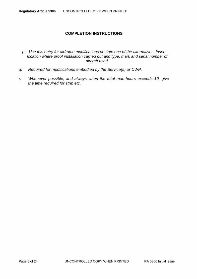
Regulatory Article 5306 UNCONTROLLED COPY WHEN PRINTED
Page 8 of 24 UNCONTROLLED COPY WHEN PRINTED RA 5306 Initial Issue
COMPLETION INSTRUCTIONS
p. Use this entry for airframe modifications or state one of the alternatives. Insert
location where proof installation carried out and type, mark and serial number of aircraft used.
q. Required for modifications embodied by the Service(s) or CWP. r. Whenever possible, and always when the total man-hours exceeds 10, give
the time required for strip etc.
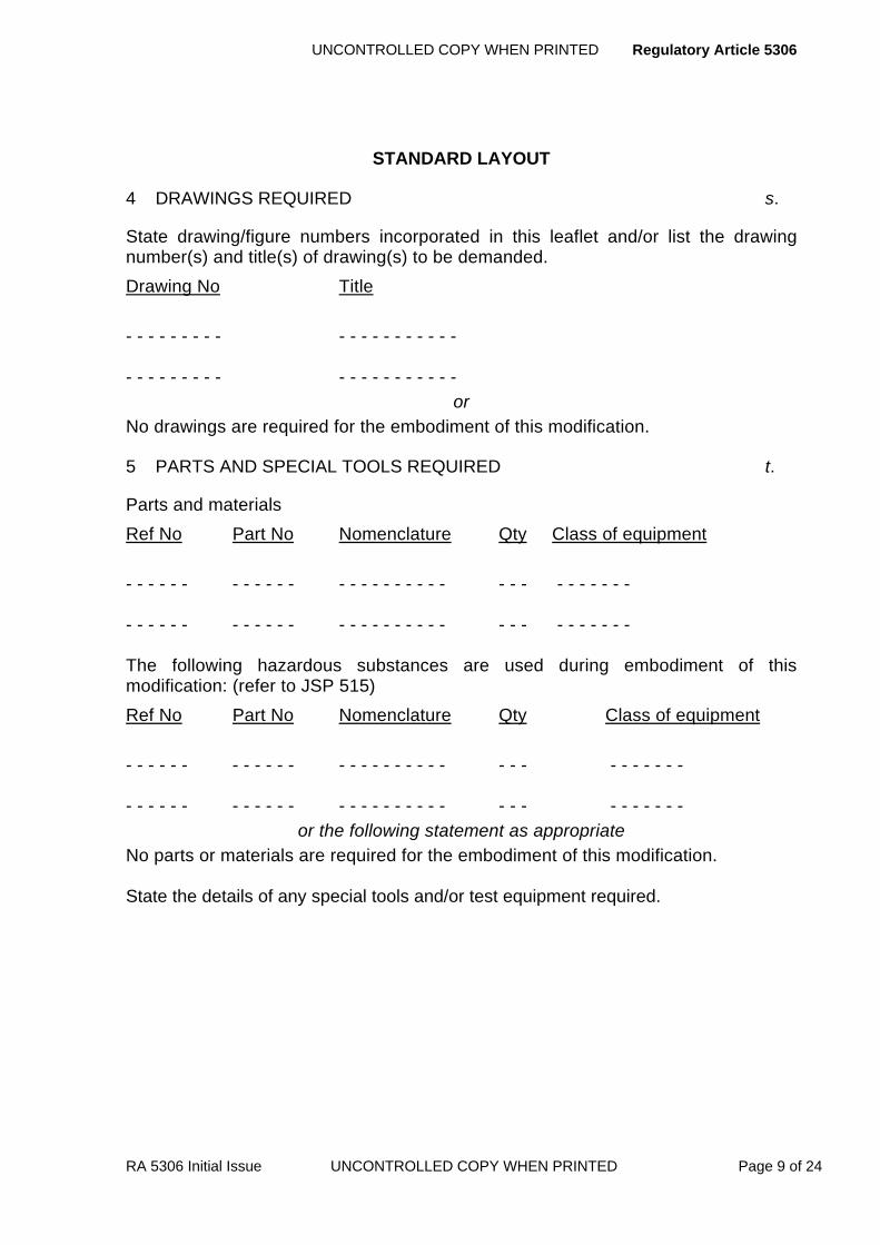
UNCONTROLLED COPY WHEN PRINTED Regulatory Article 5306
RA 5306 Initial Issue UNCONTROLLED COPY WHEN PRINTED Page 9 of 24
STANDARD LAYOUT
4 DRAWINGS REQUIRED s.
State drawing/figure numbers incorporated in this leaflet and/or list the drawing number(s) and title(s) of drawing(s) to be demanded. Drawing No Title - - - - - - - - - - - - - - - - - - - - - - - - - - - - - - - - - - - - - - - -
or No drawings are required for the embodiment of this modification.
5 PARTS AND SPECIAL TOOLS REQUIRED t.
Parts and materials Ref No Part No Nomenclature Qty Class of equipment - - - - - - - - - - - - - - - - - - - - - - - - - - - - - - - - - - - - - - - - - - - - - - - - - - - - - - - - - - - - - - - - The following hazardous substances are used during embodiment of this modification: (refer to JSP 515) Ref No Part No Nomenclature Qty Class of equipment - - - - - - - - - - - - - - - - - - - - - - - - - - - - - - - - - - - - - - - - - - - - - - - - - - - - - - - - - - - - - - - -
or the following statement as appropriate No parts or materials are required for the embodiment of this modification. State the details of any special tools and/or test equipment required.

Regulatory Article 5306 UNCONTROLLED COPY WHEN PRINTED
Page 10 of 24 UNCONTROLLED COPY WHEN PRINTED RA 5306 Initial Issue
COMPLETION INSTRUCTIONS
s. In general, drawings should be incorporated into leaflets and be of the simple line diagram or sketch type, to engineering drawing standard. Drawings or sketches submitted with a proposal should be suitable for reproduction and sufficiently large for a 2:1 reduction. For standard A4 size, the maximum size of the printed illustration (including captions, sheet number, figure number, title and security markings) is 260mm x 165mm. Line diagrams or sketches to be used as working drawings are to have all detail large enough to be easily interpreted. Photographs should only be used to complement drawings.
t. List the parts and any special tools required.
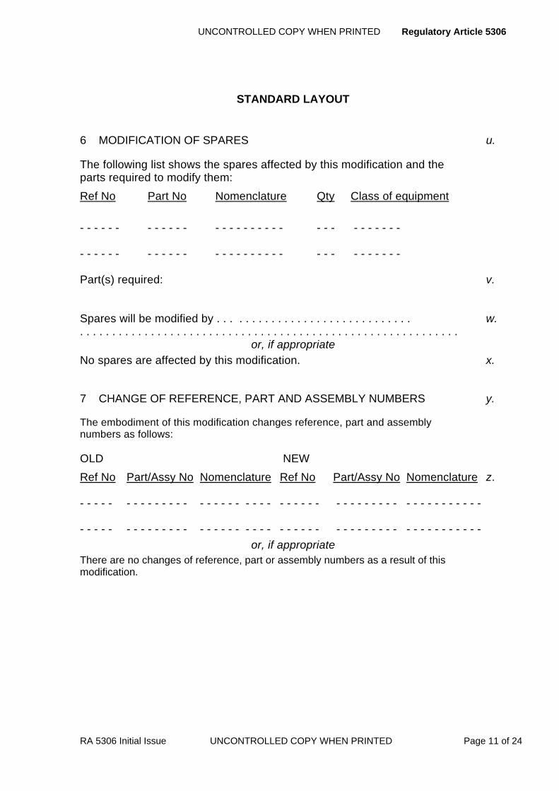
UNCONTROLLED COPY WHEN PRINTED Regulatory Article 5306
RA 5306 Initial Issue UNCONTROLLED COPY WHEN PRINTED Page 11 of 24
STANDARD LAYOUT
6 MODIFICATION OF SPARES u.
The following list shows the spares affected by this modification and the parts required to modify them: Ref No Part No Nomenclature Qty Class of equipment - - - - - - - - - - - - - - - - - - - - - - - - - - - - - - - - - - - - - - - - - - - - - - - - - - - - - - - - - - - - - - - - Part(s) required: v. Spares will be modified by . . . . . . . . . . . . . . . . . . . . . . . . . . . . . . w. . . . . . . . . . . . . . . . . . . . . . . . . . . . . . . . . . . . . . . . . . . . . . . . . . . . . . . . . . . .
or, if appropriate No spares are affected by this modification. x.
7 CHANGE OF REFERENCE, PART AND ASSEMBLY NUMBERS y.
The embodiment of this modification changes reference, part and assembly numbers as follows: OLD NEW Ref No Part/Assy No Nomenclature Ref No Part/Assy No Nomenclature z. - - - - - - - - - - - - - - - - - - - - - - - - - - - - - - - - - - - - - - - - - - - - - - - - - - - - - - - - - - - - - - - - - - - - - - - - - - - - - - - - - - - - - - - - - - - - - - - - - - - -
or, if appropriate There are no changes of reference, part or assembly numbers as a result of this modification.

Regulatory Article 5306 UNCONTROLLED COPY WHEN PRINTED
Page 12 of 24 UNCONTROLLED COPY WHEN PRINTED RA 5306 Initial Issue
COMPLETION INSTRUCTIONS
u. The spares referred to are those assemblies or components which
themselves need to be modified consequent upon the introduction of the modification. Should a spare, having other uses, be modified in such a way as to make it unsuitable for these other uses, it will have to be re-referenced for the particular application under consideration; it would therefore become a new part. Include all known stores reference and NATO stock numbers.
v. List the parts required to modify each spare, immediately below each spare listed.
w. Insert at end of list. Leave a space of five lines for Service department entry.
x. Insert after Para 6 main title, if applicable. y. The list of parts, of which the reference, part or assembly numbers are
changed shall include the spares affected as listed in Para 6. Include all known stores reference and NATO stock numbers. This paragraph refers only to those parts which are physically reworked to the new standard and not to replacement parts.
z. Omit new nomenclature if same as old.
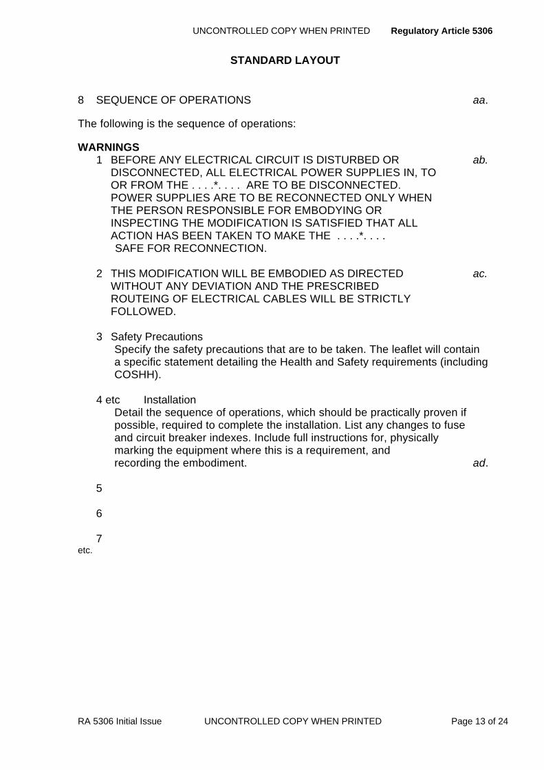
UNCONTROLLED COPY WHEN PRINTED Regulatory Article 5306
RA 5306 Initial Issue UNCONTROLLED COPY WHEN PRINTED Page 13 of 24
STANDARD LAYOUT
8 SEQUENCE OF OPERATIONS aa.
The following is the sequence of operations:
WARNINGS 1 BEFORE ANY ELECTRICAL CIRCUIT IS DISTURBED OR ab. DISCONNECTED, ALL ELECTRICAL POWER SUPPLIES IN, TO OR FROM THE . . . .*. . . . ARE TO BE DISCONNECTED. POWER SUPPLIES ARE TO BE RECONNECTED ONLY WHEN THE PERSON RESPONSIBLE FOR EMBODYING OR INSPECTING THE MODIFICATION IS SATISFIED THAT ALL ACTION HAS BEEN TAKEN TO MAKE THE . . . .*. . . . SAFE FOR RECONNECTION.
2 THIS MODIFICATION WILL BE EMBODIED AS DIRECTED ac. WITHOUT ANY DEVIATION AND THE PRESCRIBED ROUTEING OF ELECTRICAL CABLES WILL BE STRICTLY FOLLOWED.
3 Safety Precautions
Specify the safety precautions that are to be taken. The leaflet will contain a specific statement detailing the Health and Safety requirements (including COSHH).
4 etc Installation
Detail the sequence of operations, which should be practically proven if possible, required to complete the installation. List any changes to fuse and circuit breaker indexes. Include full instructions for, physically marking the equipment where this is a requirement, and recording the embodiment. ad.
5 6 7
etc.

Regulatory Article 5306 UNCONTROLLED COPY WHEN PRINTED
Page 14 of 24 UNCONTROLLED COPY WHEN PRINTED RA 5306 Initial Issue
COMPLETION INSTRUCTIONS
aa. The sequence of operations shall be in logical order. Parts to be manufactured by Service units shall be detailed first, followed by removal, dismantling, embodiment, re-numbering, re-assembly and re-fitting, and the necessary routine testing by reference to appropriate Service publications. Where work to be done by the Service(s), such as dismantling, fitting and testing is already described in other current Service instructions refer to the relevant publication reference.
When the work involved in the embodiment of the modification has to be done by the contractor (usually by return of components), and other work has to be done on the aircraft, enter only the work to be done by the Service. Although changes of reference, part and assembly numbers are listed in Para 7, the physical action required to effect such changes and also to record embodiment of the modification on the modification plate, shall be included in the sequence of operations.
When quoting both part number and reference number the part number shall
come first thus: Coupling, Part No DTD900/4516 (33C/8060-99-224-3421)
ab. Insert WARNING 1 in all modification leaflets. *Insert the main equipment concerned eg missile, aircraft simulator etc.
ac. Insert WARNING 2 in modification leaflets dealing with modifications to
weapon carrying aircraft.
ad. Each operation will be separately paragraphed.

UNCONTROLLED COPY WHEN PRINTED Regulatory Article 5306
RA 5306 Initial Issue UNCONTROLLED COPY WHEN PRINTED Page 15 of 24
STANDARD LAYOUT
9 SPECIAL TESTS AFTER EMBODIMENT ae.
1) When the modification has been embodied and inspected do the following special tests: af.
and/or, if appropriate 2) When this modification has been embodied and inspected do functional tests
of all systems which have been disturbed for the purpose of embodying this modification, in accordance with current testing instructions.
and/or, if appropriate 3) As the embodiment of this modification involves disturbance of the …*….
system, an independent check of the system will be made in accordance with 4000 series RAs. ag.
and, if appropriate 4) A flight trial is/is not required to prove satisfactory embodiment of this modification
or, if appropriate 5) No special testing is required after the embodiment of this modification but any other appropriate and associated testing will be done.
10 RECORDING ACTION ah.
When this modification has been embodied and inspected in accordance with current authorized procedures the following recording action will be taken: ai. . . . . . . . . . . . . . . . . . . . . . . . . . . . . . . . . . . . . . . . . . . . . . . . . . . .
and, if appropriate The following MOD Form 703A entry will be made against Mod ***. aj.
or, if appropriate No recording action is necessary.
11 DISPOSAL OF REDUNDANT PARTS
List and state the disposal action of all the parts removed and not reinstalled as a result of the modification under the following headings: Ref No Part No Nomenclature Qty Class of equipment - - - - - - - - - - - - - - - - - - - - - - - - - - - - - - - - - - - - - - - ak. - - - - - - - - - - - - - - - - - - - - - - - - - - - - - - - - - - - - - - -
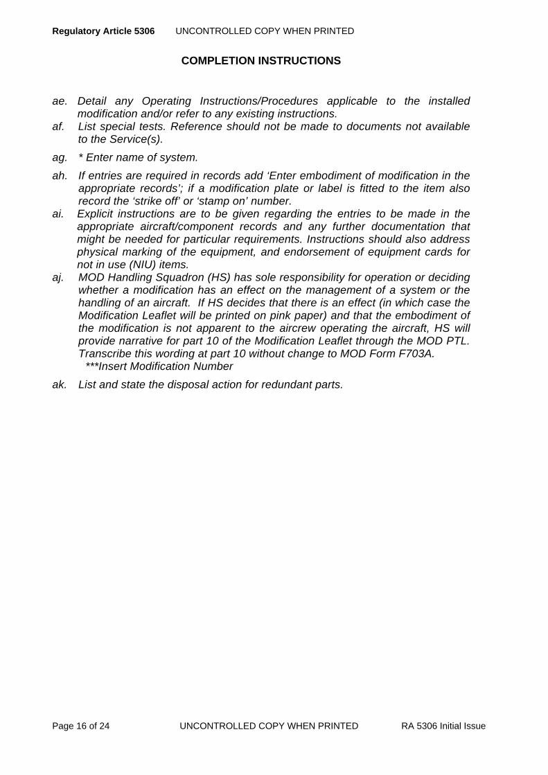
Regulatory Article 5306 UNCONTROLLED COPY WHEN PRINTED
Page 16 of 24 UNCONTROLLED COPY WHEN PRINTED RA 5306 Initial Issue
COMPLETION INSTRUCTIONS
ae. Detail any Operating Instructions/Procedures applicable to the installed modification and/or refer to any existing instructions.
af. List special tests. Reference should not be made to documents not available to the Service(s).
ag. * Enter name of system.
ah. If entries are required in records add ‘Enter embodiment of modification in the appropriate records’; if a modification plate or label is fitted to the item also record the ‘strike off’ or ‘stamp on’ number.
ai. Explicit instructions are to be given regarding the entries to be made in the appropriate aircraft/component records and any further documentation that might be needed for particular requirements. Instructions should also address physical marking of the equipment, and endorsement of equipment cards for not in use (NIU) items.
aj. MOD Handling Squadron (HS) has sole responsibility for operation or deciding whether a modification has an effect on the management of a system or the handling of an aircraft. If HS decides that there is an effect (in which case the Modification Leaflet will be printed on pink paper) and that the embodiment of the modification is not apparent to the aircrew operating the aircraft, HS will provide narrative for part 10 of the Modification Leaflet through the MOD PTL. Transcribe this wording at part 10 without change to MOD Form F703A.
***Insert Modification Number
ak. List and state the disposal action for redundant parts.
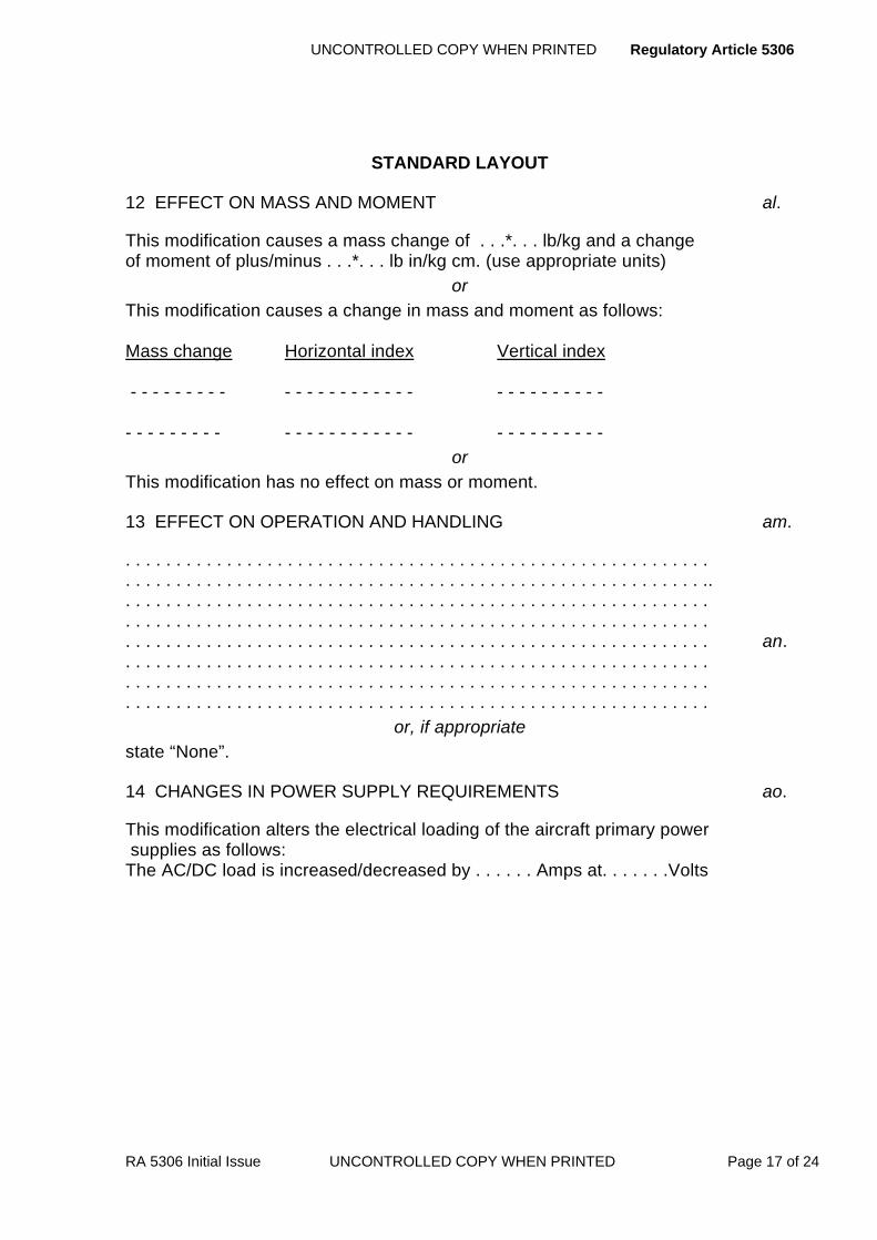
UNCONTROLLED COPY WHEN PRINTED Regulatory Article 5306
RA 5306 Initial Issue UNCONTROLLED COPY WHEN PRINTED Page 17 of 24
STANDARD LAYOUT
12 EFFECT ON MASS AND MOMENT al.
This modification causes a mass change of . . .*. . . lb/kg and a change of moment of plus/minus . . .*. . . lb in/kg cm. (use appropriate units)
or This modification causes a change in mass and moment as follows: Mass change Horizontal index Vertical index - - - - - - - - - - - - - - - - - - - - - - - - - - - - - - - - - - - - - - - - - - - - - - - - - - - - - - - - - - - - - -
or This modification has no effect on mass or moment.
13 EFFECT ON OPERATION AND HANDLING am.
. . . . . . . . . . . . . . . . . . . . . . . . . . . . . . . . . . . . . . . . . . . . . . . . . . . . . . . . . .
. . . . . . . . . . . . . . . . . . . . . . . . . . . . . . . . . . . . . . . . . . . . . . . . . . . . . . . . . ..
. . . . . . . . . . . . . . . . . . . . . . . . . . . . . . . . . . . . . . . . . . . . . . . . . . . . . . . . . .
. . . . . . . . . . . . . . . . . . . . . . . . . . . . . . . . . . . . . . . . . . . . . . . . . . . . . . . . . .
. . . . . . . . . . . . . . . . . . . . . . . . . . . . . . . . . . . . . . . . . . . . . . . . . . . . . . . . . . an.
. . . . . . . . . . . . . . . . . . . . . . . . . . . . . . . . . . . . . . . . . . . . . . . . . . . . . . . . . .
. . . . . . . . . . . . . . . . . . . . . . . . . . . . . . . . . . . . . . . . . . . . . . . . . . . . . . . . . .
. . . . . . . . . . . . . . . . . . . . . . . . . . . . . . . . . . . . . . . . . . . . . . . . . . . . . . . . . . or, if appropriate
state “None”.
14 CHANGES IN POWER SUPPLY REQUIREMENTS ao.
This modification alters the electrical loading of the aircraft primary power supplies as follows: The AC/DC load is increased/decreased by . . . . . . Amps at. . . . . . .Volts

Regulatory Article 5306 UNCONTROLLED COPY WHEN PRINTED
Page 18 of 24 UNCONTROLLED COPY WHEN PRINTED RA 5306 Initial Issue
COMPLETION INSTRUCTIONS
al. The words ‘plus’ and ‘minus’ should be used; the arithmetical signs ‘+’ and ‘-’ shall not be used. Changes should not be described as ‘negligible’ or ‘less than say ½ lb’. The units used shall be the same as quoted in the technical publication for the item concerned.
am. Insert ‘AIRCRAFT (INCLUDING INSTALLED EQUIPMENT)", "GUIDED
MISSILE" or "EQUIPMENT" as appropriate. When a modification to an aircraft or its equipment has an effect on the
management of a system or the operation or handling of an aircraft which will engender a change in the aircrew manual, full details of the effect should be given. It is important that the information should agree with that which is being prepared by the contractor for inclusion in the aircrew manual and close liaison between the design department and the chief test pilot is essential.
an. Insert: effect on normal operating and handling procedure; effect on emergency operating and handling procedure; and, for aircraft, effect on limitations and performance. ao. If applicable enter and complete the statement:

UNCONTROLLED COPY WHEN PRINTED Regulatory Article 5306
RA 5306 Initial Issue UNCONTROLLED COPY WHEN PRINTED Page 19 of 24
STANDARD LAYOUT
15 EFFECT ON SERVICING AND GROUND SUPPORT EQUIPMENT
Enter particulars of the effect on servicing and on ground support equipment including test equipment and simulators or state “None”. 16 EMC AND TEMPEST CLEARANCE EMC clearance has been given/is awaited If the aircraft has secure systems, insert: Embodiment of this modification invalidates the TEMPEST clearance until formal clearance has been received. An appropriate entry will be made in the aircraft documentation for TEMPEST cleared aircraft.
or TEMPEST clearance has been given for all aircraft.
or TEMPEST clearance is not required. 17 NIGHT VISION GOGGLES (NVG) COMPATIBILITY Detail any effect on the NVG compatibility of the aircraft/equipment or state “None”. Technically approved for . . . . . . . . . . . . . . . . . . . by. . . . . . . . . . . . . . . . . ap.
date . . . . . . . . . . . . . . . . .

Regulatory Article 5306 UNCONTROLLED COPY WHEN PRINTED
Page 20 of 24 UNCONTROLLED COPY WHEN PRINTED RA 5306 Initial Issue
COMPLETION INSTRUCTIONS
ap. Enter name of compiling contractor.

UNCONTROLLED COPY WHEN PRINTED Regulatory Article 5306
RA 5306 Initial Issue UNCONTROLLED COPY WHEN PRINTED Page 21 of 24
APPENDIX B AMENDMENTS TO DRAFT MODIFICATION LEAFLETS
AND PUBLISHED LEAFLETS
B.1 If a modification leaflet has been published, an amendment should be prepared by reference to the printed leaflet and not to the DML.
B.2 If the amendment is simple and can easily be incorporated by the Service holders of the leaflet, the amendment will be prepared in the manner and style of Annex B1 ‘Amendments to modification leaflets - specimen’.
B.3 If the changes are complex, a new draft should be submitted. If the DML has been printed, the new draft should be annotated ‘(Alteration . . . . . . . incorporated)’ and will be issued as a replacement for the existing printed leaflet. The significant changes in the new leaflet should be indicated by a black triangles thus 4.......................3
B.4 If modifications sets have been delivered by the contractor, or for no contractor parts modifications embodiment has been started, MOD will normally approve amendments to an existing leaflet to cover minor corrections which do not affect provisioning action, the work involved or the technical or operational value of the modification.
B.5 Where a proposed amendment is outside the scope of clause B.4 above, the MOD PTL will need to consider whether it is acceptable. If not acceptable as an amendment and the change is supported, it will be necessary for a further modification to be submitted. If this modification is subsequently approved a further draft leaflet should be prepared.
B.6 To assist MOD in their considerations, all draft amendments to leaflets shall be accompanied by a statement giving the necessary information as detailed in Annex B2.
B.7 Amendments should not be submitted which affect any fixed or maximum price agreement reached for the subject modification, and any draft amendment which does not affect such
agreements should be accompanied by a statement to that effect. When the costs shown on the MPF are estimates, any change of cost shown on the statement should be taken into account by
MOD when considering the proposed amendment.

Regulatory Article 5306 UNCONTROLLED COPY WHEN PRINTED
Page 22 of 24 UNCONTROLLED COPY WHEN PRINTED RA 5306 Initial Issue
ANNEX B1 AMENDMENTS TO MODIFICATION LEAFLETS - SPECIMEN
Main undercarriage AP 101B-3012-2 Mod Leaflet No 332 Introduction of uplock hook (Alteration 1)
HUNTER F1 Mk1 AIRCRAFT Amend above leaflet as follows:
1) Change ‘Introduction of uplock hook’ above to read ‘Introduction of uplock hook with modified contour’.
2) Para 1, line 2. Delete ‘a modification’ and substitute ‘Mod No SEM Hunter/6’.
3) Para 5(1)(a)(ii). Amend items 1 to 3 to read:
Ref No Part No Nomenclature Qty Class of equipment ‘26EH/.... W.96952 Template, port 1 C 26EH/.... W.96393 Template, stbd 1 C 26EH/.... AS.987 Rivet 3 C’
4) Para 5(1)(b), Item 6. Delete Qty ‘2’ and classification ‘C’ and substitute ‘4’ and ‘A’.
5) Para 5(1)(b) Add to end of list
Ref No Part No Nomenclature Qty Class of equipment ‘28W/..... SP.16/E Washer 2 C’
6) Para 8. After operation (2) insert:
NOTE Aircraft in which this modification has been embodied are to be inspected.’
7) Para 8, Operation (3) line 6. After ‘embodied’ insert ‘Mod No Hunter/8 is required’.
8) Para 8, Operations (5) and (6). Delete these two operations and re-number operations (7) to (10) as ‘(5)’, ‘(6)’, ‘(7)’ and ‘(8)’.
9) Drawing No AP 101B-3102-2/332/75, Sheet 2. Remove and substitute Drawing No AP 101B-3102-2/332/75 dated 30 February 2000 attached.
10) Drawing No AP 101B-3102-2/332/76, Sheet 4. In top left-hand corner, against ballooned Part No ‘X.234’ insert ‘PORT SIDE ONLY’.
11) After Drawing No AP 101B-3102-2/332/77, Sheet 6 attach to the leaflet the new drawing No AP 101B-3102-2/332/77, Sheet 7.
Technically approved for . . . . . . . . . . . . . . . . . . . . . . . . . . . . by . . . . . . . . . . . . . . . . . . . . (Insert contractors name) Date .............

UNCONTROLLED COPY WHEN PRINTED Regulatory Article 5306
RA 5306 Initial Issue UNCONTROLLED COPY WHEN PRINTED Page 23 of 24
ANNEX B2 STATEMENT TO ACCOMPANY DRAFT AMENDMENTS TO MODIFICATION
LEAFLETS
Amendment No to Leaflet for Mod No
(complete as appropriate) 1. Name of item affected. 2. Description of modification. (as on MPF) 3. Is corrective action required for mod sets or kits already delivered? (Answer ‘Yes’ or ‘No’) 4. Does this amendment necessitate retrospective action for items already modified to earlier
instructions? (answer ‘Yes’ or ‘No’)
Note: If the answer to either Question No 3 or 4 is ‘Yes’, Question Nos 5-15 are to be answered. If the answers to both Questions Nos 3 and 4 are ‘No’ the remaining questions need not be answered, except Question 6 which is always to be answered.
5. Give details of any other modifications affected by this amendment. (eg aircraft "cover" or
component modifications) 6. State reasons for amendment. (Give details: it is insufficient to state ‘design error’,
‘embodiment instructions incorrect’, etc.) 7. Will the approval of this amendment cause an alteration to the estimated costs given on the
MPF or equivalent for the modification? If so, by how much? 8. If mod sets or kits are affected, how many have been issued and to whom? 9. What corrective action is required for mod sets or kits already delivered? 10. Has delivery of mod sets been suspended until corrective action has been taken? 11. If additional contractor supply items are required, state when available. 12. Are additional Service supply items required? If ‘Yes’, state full details. 13. What retrospective action is required for items already modified to earlier instructions?

Regulatory Article 5306 UNCONTROLLED COPY WHEN PRINTED
Page 24 of 24 UNCONTROLLED COPY WHEN PRINTED RA 5306 Initial Issue
14. Has delivery of items been suspended until corrective action has been taken? 15. Has the contractor's working party or embodying contractor already taken corrective
action? If ‘No’, state approximate date when this will be done. Technically approved by Signature Name and address of contractor
(for use by MOD) Name and address of contractor Draft Amendment No . . . . . . . . . . . . . .. to Leaflet for Modification No . . . . . . . . . . . . . . The draft amendment proposed is (a) acceptable as an amendment (b) not considered to be necessary (c) necessary but will require to be introduced by further modification action. Signed . . . . . . . . . . . . . . . . . . . . . . Date . . . . . . . . . . . . . . . . for Ministry of Defence

UNCONTROLLED COPY WHEN PRINTED Regulatory Article 5307
RA 5307 Initial Issue UNCONTROLLED COPY WHEN PRINTED Page 1 of 6
RA 5307 – Identification and Recording of Design and Modification States of Materiel
Rationale Aircraft, installed and associated equipment, guided weapon systems and certain electronic systems require their design and modification states to be identified and recorded.
Contents 5307(1): Identification of Materiel
5307(2): Mark or Model Numbers
5307(3): Methods of Indicating a Design Change
5307(4): Modification Plates
5307(5): Y-lists of Modifications
Regulation
5307(1)
Identification of Materiel 5307(1) A military aircraft shall be identified by:
a. Name or designation. b. A letter or group of letters to indicate the operational role(s). c. Mark number.
Acceptable Means of Compliance
5307(1)
Identification of Materiel - Guided Weapon (GW) Systems 1. Every explosive store, or its inert replica, comprising part of a GW system should be identified by a nomenclature comprising a name followed by an alpha-numeric model number in a series ‘K-A’, each letter followed by a number (e.g. Rocket Motor GM, K110A1).
2. Requests for names and model numbers for GW systems including the related explosive stores should be forwarded to the PTL. For explosive stores the following information should also be supplied:
a. One copy of the filled general assembly drawing.
b. The GW system to which the store applies and its function.
c. For a non-operational store its precise purpose, e.g. practice, drill, instructional or servicing, and the nature and type of filling.
d. Where the store has undergone a design change, a brief description of the change, including its effect on operational performance or logistic considerations.
Identification of Materiel - Electronic Systems 3. Applications for installation numbers should be made to the PTL.
History Records of Equipment 4. For GW and Electronic Equipment the contractor should supply details of the history of the equipment, where required, using the appropriate Service form as specified by the PTL. Provision should be made for the history record to be included with the equipment when it is delivered.

Regulatory Article 5307 UNCONTROLLED COPY WHEN PRINTED
Page 2 of 6 UNCONTROLLED COPY WHEN PRINTED RA 5307 Initial Issue
Guidance Material
5307(1)
Identification of Materiel - Aircraft 5. The name or designation for a new type of aircraft is chosen by the MOD Service department which requires the aircraft, following consultation within the MOD and the Design Organization (DO). The PTL is responsible for promulgating the name finally chosen.
Identification of Materiel - Guided Weapon Systems 6. A new project for a guided weapon (GW) system is first given an alpha-numeric designation and later a name (e.g. ‘ET 316’ and ‘Rapier’) by the MOD. These will be promulgated by the PTL.
Identification of Materiel - Electronic Systems 7. Electronic systems may be allocated installation numbers thus:
a. ARI 1234/1 for airborne installations, or
b. FGRI 5678/1 for fixed ground installations.
8. A major new electronic system project may be given a name by the MOD and if so this will be promulgated by the PTL.
Regulation
5307(2)
Mark or Model Numbers 5307(2) A major change of design which affects the operational or
functional value of materiel, or its interchangeability, shall be identified by the introduction of a new mark or model and NATO number.
Acceptable Means of Compliance
5307(2)
Mark or Model Numbers 9. Where mark numbers are used the designation ‘Mark 1’ should be allotted to the first design standard of a new item of materiel, even though it may not be envisaged that later design standards will be introduced.
10. There may be in existence at the same time variants within a mark or model due to the introduction of modifications which are not fully retrospective, eg. to meet particular Service requirements. The procedure set out in RA 5307(5) should be applied to all variants within a mark or model. Such variants should be recorded in the configuration status record (CSR).
11. The introduction of a new mark or model number involves the formation of an additional CSR; this should be suitably linked to those for previous marks (see the DME 5200 series).
Aircraft 12. Proposals for changes in role letters or mark numbers of Service aircraft should be submitted with full supporting details to the PTL.
13. Military aircraft of UK manufacture sold abroad are distinguished by mark numbers normally commencing at 50. Requests for a mark number should be made to the PTL stating the British Service description of the aircraft and the name of the purchasing country.
Equipment 14. Items of equipment should preferably be given a mark (or type) number by the contractor which will enable variants of the original item to be readily distinguished (i.e. without necessarily quoting a part number or a NATO stock number (NSN)). Proposals for changes in mark number should be made in accordingly.

UNCONTROLLED COPY WHEN PRINTED Regulatory Article 5307
RA 5307 Initial Issue UNCONTROLLED COPY WHEN PRINTED Page 3 of 6
Guidance Material
5307(2)
Mark or Model Numbers - Aircraft 15. New mark numbers are allocated by the MOD Service department to succeeding variants of an aircraft type regardless of the placing of production orders; they are not formally promulgated until the manufacture of production aircraft or a conversion programme has been approved.
16. Mark number changes are also made as a result of major equipment installation changes which alter the performance or operational use of the aircraft or otherwise result in its segregation in Service. Such design changes may alternatively be identified by the addition of a suffix to the mark number, when subsequent mark numbers have already been used and the use of the next available number would imply greater design changes than have actually been made.
Mark or Model Numbers - Equipment 17. When a new variant of an item of equipment is introduced by modification action, the change in mark number will be agreed by the appropriate modifications committee.
18. If a new variant of an item of equipment will be introduced without modification action, the PTL will consider the need for a change in mark number.
19. For a variation to an installation in electronic systems the stroke number is increased from the original stroke 1, e.g. ARI 1234/2.
Markings 20. All items of materiel and their packaging are required to be identified by marking in accordance with the relevant design requirements and specifications.
Regulation
5307(3)
Methods of Indicating a Design Change 5307(3) The PTL and the DO shall agree the method to be used to
indicate that an item is the subject of a design change.
Acceptable Means of Compliance
5307(3)
Methods of Indicating a Design Change - Change of DO / Contractors Part Number 21. Where the DO/Contractor’s drawing issue number is included in the part number changes in issue number arising from modifications should be clearly distinguishable from those used to incorporate amendments. The proposed method should be submitted to the appropriate PTL.
Design Change in Detail Parts 22. A modification to a detail part should be identified by a change of the DO/contractor’s part number.
Design Change in Subassemblies 23. A design change in a subassembly which does not affect interchangeability but which cannot be regarded as an amendment requires a modification only to the subassembly that this should be recorded on the modification plate and/or log card for the item concerned. Where it has been agreed that a modification plate cannot be fitted, the part number for the item should be changed.
Design Changes in Main Assemblies 24. A modification to a main assembly which does not affect interchangeability should be recorded on the modification plate. When an item does not have a modification plate the part number should be changed.

Regulatory Article 5307 UNCONTROLLED COPY WHEN PRINTED
Page 4 of 6 UNCONTROLLED COPY WHEN PRINTED RA 5307 Initial Issue
Guidance Material
5307(3)
Methods of Indicating a Design Change 25. The agreed method of indicating design change is additional to any change in the NSN which may be required to identify the modified item.
26. The Services are to be able to identify the design state of all items subject to modifications which affect interchangeability (RA 5201 refers) or which require retrospective action, i.e. modifications which need to be embodied retrospectively including embodiment on removal or on replacement.
Change of DO / Contractors Part Number 27. For entry on a Modification Plate and/or Log Card, the modification number to be recorded is that authorized by the appropriate modification committee.
28. For Identification by Painting or Marking a Symbol on the Item, this may be used to indicate a design change to an item which is incapable of bearing the normal marking. The precise method of identification will be agreed between the PTL and the DO and will be described in the appropriate technical publication topic 2/category 8 leaflet.
Design Change in Subassemblies 29. A design change in a subassembly which affects interchangeability requires a change in its part number and a modification to the next higher assembly which itself may have to be treated as a subassembly.
Design Change in Main Assemblies 30. A modification to a main assembly which affects interchangeability requires a change of part number.
Design Changes in Guided Weapon Systems Explosives Stores 31. These are identified by a change to the alpha-numeric model number (paragraph 1 refers) as follows:
a. A change in operational characteristics by a change in the number following the letter ‘K’;
b. Change in logistic characteristics by a change in the number following the letter ‘A’.
Regulation
5307(4)
Modification Plates 5307(4) All main assemblies, line replaceable units (LRUs) or line
replaceable items (LRIs) etc, shall be fitted with a modification plate.
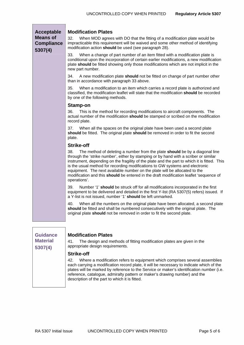
UNCONTROLLED COPY WHEN PRINTED Regulatory Article 5307
RA 5307 Initial Issue UNCONTROLLED COPY WHEN PRINTED Page 5 of 6
Acceptable Means of Compliance
5307(4)
Modification Plates 32. When MOD agrees with DO that the fitting of a modification plate would be impracticable this requirement will be waived and some other method of identifying modification action should be used (see paragraph 28).
33. When a change of part number of an item fitted with a modification plate is conditional upon the incorporation of certain earlier modifications, a new modification plate should be fitted showing only those modifications which are not implicit in the new part number.
34. A new modification plate should not be fitted on change of part number other than in accordance with paragraph 33 above.
35. When a modification to an item which carries a record plate is authorized and classified, the modification leaflet will state that the modification should be recorded by one of the following methods.
Stamp-on 36. This is the method for recording modifications to aircraft components. The actual number of the modification should be stamped or scribed on the modification record plate.
37. When all the spaces on the original plate have been used a second plate should be fitted. The original plate should be removed in order to fit the second plate.
Strike-off 38. The method of deleting a number from the plate should be by a diagonal line through the ‘strike number’, either by stamping or by hand with a scriber or similar instrument, depending on the fragility of the plate and the part to which it is fitted. This is the usual method for recording modifications to GW systems and electronic equipment. The next available number on the plate will be allocated to the modification and this should be entered in the draft modification leaflet ‘sequence of operations’.
39. Number ‘1’ should be struck off for all modifications incorporated in the first equipment to be delivered and detailed in the first Y-list (RA 5307(5) refers) issued. If a Y-list is not issued, number ‘1’ should be left unmarked.
40. When all the numbers on the original plate have been allocated, a second plate should be fitted and shall be numbered consecutively with the original plate. The original plate should not be removed in order to fit the second plate.
Guidance Material
5307(4)
Modification Plates 41. The design and methods of fitting modification plates are given in the appropriate design requirements.
Strike-off 42. Where a modification refers to equipment which comprises several assemblies each carrying a modification record plate, it will be necessary to indicate which of the plates will be marked by reference to the Service or maker’s identification number (i.e. reference, catalogue, admiralty pattern or maker’s drawing number) and the description of the part to which it is fitted.

Regulatory Article 5307 UNCONTROLLED COPY WHEN PRINTED
Page 6 of 6 UNCONTROLLED COPY WHEN PRINTED RA 5307 Initial Issue
Regulation
5307(5)
Y-lists of Modifications 5307(5) Before deliveries to the Service(s) of a new type or mark of
materiel begin, a survey of modifications shall be made by the Local Technical Committee (LTC) or equivalent.
Acceptable Means of Compliance
5307(5)
43. For GW systems the Y-list should be confined to a particular breakdown of the system as exemplified by the part record sheet and should be identified by a suffix or number denoting the part record sheet to which it refers, and serial number.
44. A Y-list should be compiled showing the numbers of those modifications which comprise the standard for initial deliveries.
45. For aircraft the list should be known as ‘Modification Standard No (quoting type and mark of aircraft) Y/1 (or 2 or 3 etc.)’ and this should show the standard being worked to on the production line. The log cards for each individual aircraft should show any variations from the above standard.
46. The LTC should state in its minutes the serial number of the materiel from which the new list will take effect.
47. For aircraft the modification standard, after approval by the LTC, should be reported to the aircraft modification committee (or equivalent) by means of the narrative minutes of the LTC.
48. For aircraft, a copy of the modification standard should be entered on the MOD Form 753, which should quote the number of the modification standard and should show the plus and minus deviations from it.
49. The Y-list number of the standard should be stamped on the modification plates of the aircraft, e.g.: Sentinel R. Mk.1 Y/1, plus ..........., minus ..............
Guidance Material
5307(5)
50. Lists of modifications or Y-lists are master lists of the modifications which must be embodied in the equipment during production and are prepared to simplify the recording of modifications. However, Y-list serial numbers may be quoted with plus for additional modifications or minus for those not embodied.
51. Y-lists are prepared by the DO when requested by the LTC.
UNCONTROLLED COPY WHEN PRINTED Regulatory Article 5308
RA 5308 issue 3 UNCONTROLLED COPY WHEN PRINTED Page 1 of 35
RA 5308 - Service Modifications
Rationale In certain circumstances the MOD PT may use the Service Modification (SM) process to change the design of their aircraft or equipment in preference to the Design Organization Modification (DM) route. An SM provides a PT with the flexibility to embody aircraft and equipment modifications of either an urgent, special or short-term nature, or for trial purposes, or to address a safety issue, or to increase capability, improved availability or maintainability
Contents 5308(1): Service Modifications
5308(2): Control of Service Modifications
5308(3): Design Record of Service Modifications
Regulation
5308(1)
Service Modifications
5308(1) The Service Modification (SM) procedure shall be used by PT to embody modifications when the Design Organization (DO) Modification procedure will not meet the required timeframe, or where a PT believes that it is more cost-effective to introduce and support an SM.
Acceptable Means of Compliance
5308(1)
1. Every SM should be supported by its own Safety Case, assessed against and integrated into, the whole aircraft Safety Case.
2. This RA should not apply to SM on:
a. Rationalized weapons, ammunition and explosives.
b. Equipment supplied or maintained by Government agencies outside the MOD, unless a prior agreement has been arranged with the provider.
c. Equipment on loan to the MOD, unless a prior agreement has been arranged with the provider.
d. Equipment that forms part of a Contractor Logistic Support agreement where the Contractor owns the equipment, unless a prior agreement has been arranged
3. PT should be responsible for the management of the modification process supported by a committee of stakeholders. Detailed information on Modification Committees is contained in RA 5303 and RA 5304
4. The PT should give due consideration to the following, non exhaustive, list prior to, and during, the SM process:
a. Safety and risk management.
b. Configuration management.
c. Through-life management and support.
d. Impact on the RTS.
e. Effects on the Statement of Operating Intent and Usage (SOIU).
f. Aircraft equipment clearances.
g. Trials plan.
h. Obtaining independent and specialist advice.
i. Availability of resources.

Regulatory Article 5308 UNCONTROLED COPY WHEN PRINTED
Page 2 of 35 UNCONTROLED COPY WHEN PRINTED RA 5308 Issue 3
j. Identification of funding to cover the various phases of the SM process.
k. ADS amendments.
l. Embodiment programme, including aircraft and equipment in storage.
m. Manufacturing control.
n. Reliability and maintainability.
o. Repair and reconditioning.
p. Support and test equipment.
q. Training.
r. Aircraft security accreditation; JSP 440 refers.
5. PT should be responsible for:
a. Cancelling and reissuing an SM under a new number if changes to the existing SM invalidates aircraft or equipment clearances, or affects the Safety Case.
b. Ensuring that SM embodied for trials purposes are either removed, or formally embodied at the end of the trial.
c. . Publishing SM in the Topic 2(N/A/R)2 in accordance with MAP Chapter 8.4.
Guidance Material
5308(1)
6. The SM procedure supersedes all previous methods of Service managed design change including; Service Engineered Modifications, Special Trial Fits, Service Engineered Radio Installation Modifications, Temporary Radio Installation Modifications, Naval Service Modifications and Typed Air Station Modifications.
7. Contrary to the implied meaning, SM do not restrict PT to employing only in-service resources to scheme, trial or embody an SM. In the majority of cases, the decision to proceed with an SM in preference to a DM will be as a result of time or cost factors rather than for technical reasons. However, whenever the SM method is used, the PT will consider the through-life costs of supporting the modification.
8. PT are to use appropriate elements of the SM process and procedures to safely introduce or trial their design changes, and may elect to change the order and to combine stages to meet individual project requirements. This is permitted provided that risks are adequately assessed and that the necessary clearances and approvals are provided by the PT and Release to Service (RTS) authorities at appropriate stages of the process.
9. This RA applies to the embodiment of SM for:
a. Design changes to single aircraft, part or whole fleet.
b. Trial purposes, where modifications are embodied on a single or small number of aircraft for a limited period to:
(1) Test the effectiveness of new equipment and operational software.
(2) Test the effectiveness of a potential design change.
(3) Evaluate the operational capability of an airborne system.
(4) Evaluate new tactics.
(5) Measure in-flight parameters.
10. Appropriate phases/activities of the SM procedure may be used for evaluation or for trials purposes. It must only be incorporated into a limited number of aircraft or equipment for a specified period, then removed, inhibited or superseded by a DM or by completing the outstanding phases/activities of the SM procedure. It will be supported by its own Safety Case, which will be assessed against the whole aircraft Safety Case.

UNCONTROLED COPY WHEN PRINTED Regulatory Article 5308
RA 5308 Issue 3 UNCONTROLED COPY WHEN PRINTED Page 3 of 35
11. PT will need to identify funding for the various stages of the SM process and seek or confirm financial approval accordingly.
12. A simplified overview of the SM process is outlined in Annex A and described below. Annex B provides the detailed procedure for SM for aircraft and associated equipment.
a. Requirement - An originator identifies the need for a design change to an aircraft type or associated equipment to meet a safety, operational or engineering requirement.
b. Modification Proposal - The originator submits a formal proposal for a design change to the appropriate PT.
c. Feasible Solution - The PT identifies a feasible solution to address the requirement, with assistance from specialist organizations, where appropriate. This phase may include results from a feasibility study and/or consideration of safety and support issues. If an SM is the preferred solution, the following processes will apply.
d. Funding - The PT confirms that the necessary funding is available to cover all stages of the SM process before accepting and progressing the proposal, including the requirement to modify, as applicable, any platform-associated Synthetic Training Equipment.
e. Accept Proposal - If the PT accepts the proposal, the PT initiates actions to progress the proposal to the next stage of the SM process.
f. Initiation Meeting - An initiation meeting is held with all appropriate stakeholders to consider the outline design and to ensure that safety, airworthiness, operational, engineering, support and training risks and issues are addressed. Where appropriate, specialist advice, support, clearances and endorsements are obtained. During the meeting organizations are identified, tasked and authorized to undertake appropriate stages of the process and the PT and RTS Authority (RTSA) are expected to agree what evidence will be produced to enable the RTSA to incorporate the SM into the RTS. An initiation certificate is raised as the authority to proceed with the detailed design, production of the Draft SM Leaflet (DSML) and embodiment of an SM Trial Installation (TI).
g. Develop SM - The PT selects and tasks a competent DO, in accordance with RA5312, to undertake appropriate elements of the proposal progression, including SM Safety Case production, SM design and development.
h. Trial Installation (TI) - A TI is conducted to prove the practicality of the SM, identify parts and any additional trade skills or training requirements, and to provide the detailed information necessary to prepare the draft modification instruction. Where an SM is a one-off requirement, eg for a single aircraft, it may be appropriate to combine the TI with the SM embodiment referred to in paragraph m below.
i. Clearance Meeting - A clearance meeting is held to give final approval on the suitability of the SM. The meeting determines if a Proof Installation (PI) is required and, subject to satisfactory PI and trial reports, decides whether to proceed to full production and embodiment of the SM. Critical to the decision to proceed is the stakeholders’ assessment of the SM Safety Case and how it affects the whole aircraft Safety Case. The RTSA will be expected to confirm to the meeting that sufficient evidence exists to enable clearance for the SM flight trials to be given, and what, if any, further evidence will be needed to incorporate the SM into the RTS. The meeting confirms equipment clearances and criteria for the SM kit production and embodiment programme, any PI requirements, functional or ground trials and clearance for flight trials.
j. Flight Trials - If tasked by the clearance meeting and approved by the RTSA, authorized flight trials are conducted to validate the SM, typically where aircrew operations and aircraft handling are affected. A flight trial report is produced to confirm satisfactory operation/performance of a modification,
Regulatory Article 5308 UNCONTROLED COPY WHEN PRINTED
Page 4 of 35 UNCONTROLED COPY WHEN PRINTED RA 5308 Issue 3
identify problems and provide further evidence to support incorporation of the SM into the RTS.
k. Proof Installation - If required, a PI of the SM is conducted and the findings used to update the design records and engineering publications, where appropriate. RA5312 refers.
l. Configuration Control and Embodiment - To maintain configuration control, before issuing the SM the affected aircraft or equipment design records are updated and sealed and the ADS amended in accordance with RA5311. If the PT deems appropriate, this phase may include the implementation of DO cover modification action in accordance with RA5313. The SM is incorporated in the RTS for operational flying.
m. Embodiment - The PT approves and arranges for the publication and distribution of the SM and initiates the embodiment programme as agreed with the Front Line Command at the clearance meeting. The PT arranges for the provision of sufficient modification kits to meet the agreed programme at all lines of maintenance.
n. Monitor and Review Embodiment - The PT monitors and reviews the embodiment to:
(1) Maintain strict configuration control over the platform.
(2) Assess the effectiveness of the SM in meeting the requirement.
(3) Identify and resolve any problems in the embodiment programme.
(4) Incorporate lessons learnt into future programmes
Regulation
5308(2)
Service Modifications
5308(2) The DO shall identify in the Configuration Management Plan (CMP) how SM are controlled and incorporated into the materiel design records and shown in the Configuration Status Record (CSR).
Acceptable Means of Compliance
5308(2)
13. The CMP should include Service Modification control procedures that address each of the points contained in the Guidance Material below, noting that the DO should verify that SM does not affect the safety of the aircraft.
14. DO advice should be provided to the appropriate PTL so that it can be taken into account before Approval In Principle (AIP) is given for the detailed preparation of the SM. The PTL may give AIP to a SM before DO advice is received.
15. If the DO has any comments on the modification he should advise the PTL.
16. Any incompatibility between a contractor’s proposed modification and a SM should be reported to the Local Technical Committee (LTC); RA 5303 refers.
Guidance Material
5308(2)
17. A summary of the action required in altering design records to show details of modifications managed by the Service is contained in RA 5308(3). This includes the actions for the annotation of design records so as to minimise conflict between the proposed SM and any other SM and/or contractors’ modification.
18. The PTL is responsible for ensuring the safe introduction of design changes resulting from the SM process. This involves an assessment of the affects of the SM on the aircraft or equipment integrated logistics support and whole aircraft Safety Case. The PTL may involve the DO in the review and update the aircraft Safety

UNCONTROLED COPY WHEN PRINTED Regulatory Article 5308
RA 5308 Issue 3 UNCONTROLED COPY WHEN PRINTED Page 5 of 35
Case and RTS.
19. The primary responsibility of the DO will verify that the SM design does not affect the Safety of the aircraft. The subsequent raising of a contractor’s cover modification does not abrogate the responsibility of the PTL.
20. PTL will normally seek advice from the DO on a SM proposal, especially when it could :
a. Interfere with any design change already in hand or being considered.
b. Require safety or specialist testing.
c. Require significant re-design if a cover modification is being considered.
d. Require cost estimates for changes to design records.
e. Require an assessment on its compatibility with other aircraft systems or equipment.
21. The PTL may, if necessary, authorize expenditure under the appropriate item in the PDS contract for work required when seeking advice from the DO on a SM proposal.
22. The PTL decision not to seek or comply with DO advice, or to embody a SM before obtaining DO advice, will only be taken when exceptional circumstances prevail. In the case of a SM embodied before or without DO advice, the PTL concerned takes full responsibility for the effects of the SM on the airworthiness of the complete aircraft. This includes not only the effects on the system directly modified, but also any inadvertent cross-linking effects on the rest of the aircraft that are directly attributable to the SM.
23. After AIP has been given the PTL will forward the Service draft modification leaflet to the DO for consideration in accordance with RA 5106(1).
24. Where AIP is not given the MOD PTL will advise the DO so that the temporary annotation in the design records (RA 5308(3)) can be deleted.
25. When the preparation of a SM has been completed, full details in the form of an equipment AP Topic 2(N/A/R)2 leaflet incorporating the Service modification leaflet and/or drawings will be presented to the LTC.
Cover modifications 26. SM can be useful to satisfy short term or limited applicability requirements, but where there is a need to make the modification a permanent change, to update publications and to ensure long term provisioning of spares, a DO cover modification may be sought.
27. A DO cover modification incorporates details of the SM in the equipment CSR.
28. Where the SM satisfies the design standards that the DO is contracted to maintain, the DO may adopt the SM design and produce a cover modification which ‘is satisfied by’ the SM.
29. Where the SM does not satisfy the contracted design standards, the DO may redesign the modification.
30. A cover modification may be necessary to enable:
a. The DO to maintain effective configuration management by the maintenance of design records. This will avoid confusion in considering later design changes when there is significant engineering content in the modification managed by the Service, and to provide a definitive design standard when new manufacture, repair or overhaul is anticipated or when spares are expected to be ordered.
b. Changes to be made to AP to show the pre and post SM standard to avoid confusion and potential airworthiness problems during servicing and maintenance of materiel.
31. The changes to design records and AP are to be limited to the minimum necessary to achieve the above objectives, taking account of such factors as the

Regulatory Article 5308 UNCONTROLED COPY WHEN PRINTED
Page 6 of 35 UNCONTROLED COPY WHEN PRINTED RA 5308 Issue 3
expected out of service date for the materiel and the availability of funds. When industry is not required to carry out any manufacturing action or to embody modifications, changes to design records are to be limited to those shown in para. 40.
32. The anticipated costs of preparing a cover modification, and its incorporation, will be evaluated by the PTL.
33. The PTL may decide at the LTC that a change to the design records or AP is unjustified for any reason.
34. A cover modification may be classified to supersede the SM when further design work by the contractor is required or to satisfy the SM when no further design work is required. In the latter case design responsibility rests with the Service.
35. The evidence on the Modification Proposal Form (MPF) will show clearly why the LTC considers a cover modification is required.
Regulation
5308(3)
Design Record of Service Modifications 5308(3) The DO shall maintain formal and detailed design records of
Service Modifications.
Acceptable Means of Compliance
5308(3)
36. The DO should incorporate the SMs records into the overall design records in order:
a. Maintain at the DO a comprehensive design record of the current aircraft design configuration, with appropriate entries to show those SM which do not have the support of the DO.
b. Assist in the inspection of items which incorporate SM.
c. Provide data for use on repair and reconditioning contracts.
d. For reference to avoid possible clashes with the design of contractor’s future modifications.
37. The records should consist of:
a. Copies of the drawings and any documents defining the SM.
b. Temporary and permanent notations in an index of SM maintained as an appendix to the CSR. The index should list the SM number, title and applicability, and any related contractor cover modification.
c. Temporary and permanent notations in general assembly (GA) drawings of the aircraft, systems, and major equipments.
d. Permanent changes, following classification of the relevant cover modification, to design records.
Note that the preparation (and amendment as necessary) of the above records does not imply the contractor’s acceptance of technical responsibility for the design of SM (para 19).
38. The records should be prepared and amended in the following stages:
a. Initial advice given by contractor: temporary notation in the index and GA of SM.
b. The PTL decides not to proceed with the Service modification: delete the temporary notations.
c. LTC decision - no cover modification required: change the temporary notation as at para 37.b) to a permanent notation.

UNCONTROLED COPY WHEN PRINTED Regulatory Article 5308
RA 5308 Issue 3 UNCONTROLED COPY WHEN PRINTED Page 7 of 35
d. Cover modification classified – to satisfy the SM:
(1) An order for contractor spares, or future manufacture, repair or reconditioning by contractor NOT expected: Limited design incorporation as paragraph 39, changing the temporary notation in the index and GA of SMs to a permanent notation;
(2) An order for contractor spares, or future manufacture, repair or reconditioning by contractor IS expected: Full design incorporation, changing the temporary notation in the index of SMs to a permanent notation.
e. Cover modification classified: to supersede the SM. In this case further design work is required, and normally the contractor will be involved in further manufacture of production items or spares manufacture. Full design incorporation is required, changing the temporary notation in the index of SM to a permanent notation.
Limited design incorporation 39. When no manufacturing action and no modification embodiment is required from the contractor, the work carried out as design incorporation should be restricted to the minimum.
40. Detailed requirements, which should be reflected in the CMP are:
a. Preparation of the modification sheets which should reflect the limited drawing changes.
b. Incorporation of the modification in the master design records which should normally be limited to making minimum changes and annotations to major drawings (GA and assemblies) to enable the contractor to maintain control of the design and production. This should include aspects of strength, space, loading, electrical loading and distribution.
c. Amendment of the CSR and type record as appropriate.
d. Amendment of Appendix A where appropriate.
e. Amendment of AP.
41. When the above case applies the contractor should make a statement in the Supporting Evidence box of the Modification Proposal Form as follows: “The work under design incorporation will be restricted to the minimum as detailed in RA 5308(3) paras 40, 41, and 42. Man hours and cost estimates for embodiment by the contractor cannot be made without further investigation.”
Repair and reconditioning contracts 42. It is normally a condition of repair and reconditioning contracts for MOD aircraft and equipment that SMs should be brought to a serviceable condition by the contractor during such work. It follows, therefore, that the contractor should not remove any SMs when aircraft or equipment are returned from the Services to the contractor unless they are incompatible with the modification state to which they are being prepared
Guidance Material
5308(3)
43. For limited design incorporation a draft modification leaflet will not be required.
44. Where Service Modifications require the installation of unapproved equipment, the PTL initiating the requirement will be responsible for obtaining approval for the equipment
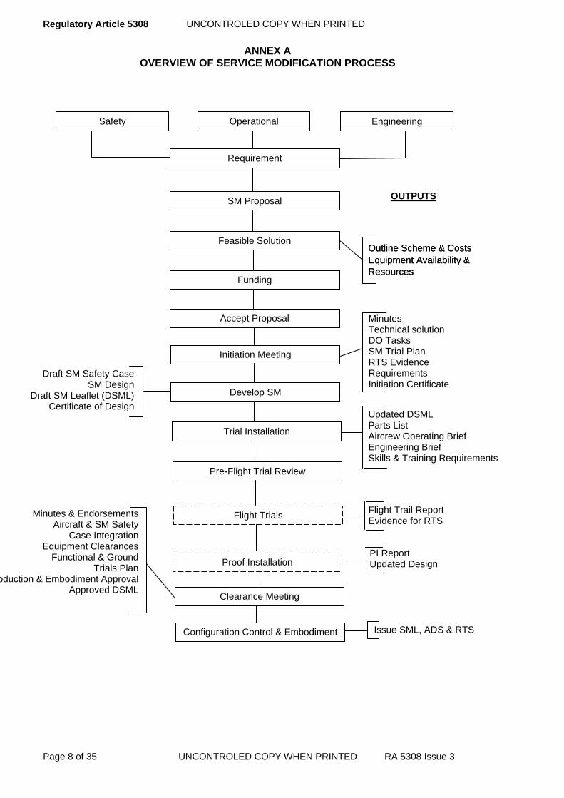
Regulatory Article 5308 UNCONTROLED COPY WHEN PRINTED
Page 8 of 35 UNCONTROLED COPY WHEN PRINTED RA 5308 Issue 3
ANNEX A OVERVIEW OF SERVICE MODIFICATION PROCESS
Minutes & Endorsements Aircraft & SM Safety
Case Integration Equipment Clearances
Functional & Ground Trials Plan
oduction & Embodiment Approval Approved DSML
Flight Trail Report Evidence for RTS
Proof Installation
Minutes Technical solution DO Tasks SM Trial Plan RTS Evidence Requirements Initiation Certificate
Outline Scheme & Costs Equipment Availability & Resources
Draft SM Safety Case SM Design
Draft SM Leaflet (DSML) Certificate of Design
OUTPUTS
ted DSML Parts List Aircrew Operating Brief Engineering Brief Skills & Training Requirements
Upda
Feasible Solution
Funding
Accept Proposal
Initiation Meeting
Operational Engineering
Requirement
Safety
SM Proposal
Develop SM
Trial Installation
Pre-Flight Trial Review
Flight Trials
Outline Scheme & Costs Equipment Availability & Resources
Clearance Meeting
PI Report Updated Design
sue SML, ADS & RTS IsConfiguration Control & Embodiment
UNCONTROLED COPY WHEN PRINTED Regulatory Article 5308
RA 5308 Issue 3 UNCONTROLED COPY WHEN PRINTED Page 9 of 35
ANNEX B SERVICE MODIFICATION PROCEDURE
1 General
1.1 Introduction This Annex contains the procedures for Service Modifications (SM) to aircraft and associated equipment. It must be read in conjunction with RA5311 and RA5312, and with JSP 886. These procedures detail the essential steps required to ensure that:
1 SMs are developed and embodied safely. 2 Detailed records of the SM process are kept. 3 Configuration management is maintained. These steps are mandatory but may be supplemented by local procedures.
1.2 Associated publications This RA is associated with the following publications:
1 Def Stan 05-57 – Configuration Management of Defence Materiel. 2 RA5300 series in general.
1.3 Service Modification (SM) forms, leaflets and questionnaires The following associated forms, leaflets and questionnaires are contained in the MAP-02:
1 MOD F755(SM1) – Service Modification Proposal. 2 MOD F755(SM2) – Service Modification Safety and Support Questionnaire. 3 MOD F755(SM3) – Service Modification Amplification of Proposal. 4 MOD F755(SM4) – Service Modification Proposal Progression. 5 MOD F755(SM5) – Service Modification Initiation Certificate. 6 MOD F755(SM6) – Service Modification Engineering Trial Installation and Pre-Flight Trial
Review. 7 MOD F755(SM7) – Service Modification Aircraft and Equipment Trial Form. 8 MOD F755(SM8) – Service Modification Flight Trial and Engineering Report. 9 MOD F755(SM9) – Service Modification Clearance Certificate. 10 MOD F755(SM10) – Service Modification Authority for Extension or Transfer. 11 MOD F755(SM11) - Service Modification Change or Cancellation Proposal. 12 MOD F755(SM12) - Service Modification Leaflet Amendment Proposal.
2 Overview
The following paragraphs and figure describes the four distinct phases of the generic SM development process:
1 Proposal, acceptance and registration. 2 Proposal progression and formal approval. 3 Initiation, development and pre-flight review. 4 Clearance, approval, embodiment and review. The SM process and associated activities detailed in the paragraphs below are to be followed.
Throughout the SM process all approvals and clearances are to be approved by a competent person with the appropriate Letter of Airworthiness Approval (LOAA). Any divergence from the SM process will be similarly approved.

Regulatory Article 5308 UNCONTROLED COPY WHEN PRINTED
Page 10 of 35 UNCONTROLED COPY WHEN PRINTED RA 5308 Issue 3
3 Phase 1 - Proposal, acceptance and registration
Phase 1 of the SM process includes the proposal, acceptance and registration; all elements of Phase 1 are to be completed prior to entering Phase 2 of the SM process.
3.1 SM proposal An organization identifying a requirement for a design change will submit MOD F755 (SM1) - Service Modification Proposal - to the relevant Project Team (PT) to:
1 Improve safety or airworthiness. 2 Satisfy an operational need. 3 Improve capability, availability or maintainability. 4 Support a trial. 5 Meet a minor user requirement. Originators are to include details of the requirement and provide a supporting impact statement. When appropriate, the impact statement must highlight the implications of not satisfying the requirement.
3.2 Safety and Support Questionnaire (SSQ) MOD F755 (SM2) - Safety and Support Questionnaire (SSQ) - will be raised during the proposal phase to identify safety and business risks during the early stages of the SM process. Subsequently, the completed SSQ will assist in producing the SM Safety Case. The SM Safety Case will be used to assess the effect of the SM on the whole aircraft Safety Case and enable the PT to make a balanced decision on whether, or how, to proceed with the SM. The content of the SSQ is provided for guidance only: the list is not exhaustive and PTs are expected to include additional subjects as necessary, ensuring that all hazards are identified and addressed. DOs are normally tasked by the PT to complete the SSQ on their behalf. PTs may also task the DO or other competent organization to conduct a detailed risk assessment of the SM proposal and appropriate SSQ items during the proposal progression phase.
3.3 Amplification of Proposal (AOP) To enable the PT to make an informed judgement on whether or not to proceed with a complex SM, the PT may task the DO to provide further information on the proposed SM by raising MOD F755 (SM3) - Amplification of Proposal (AOP). To prevent unnecessary effort being expended on preparing the Draft SM Leaflet (DSML), the AOP report must be considered before the DSML is written. PTs may request support from other agencies to assist the DO in producing the AOP report.
3.4 Feasibility study If further information or analysis is needed on the proposal to identify a feasible solution to meet the requirement, the PT may undertake, or task a competent organization to conduct, a feasibility study.
3.5 Identify a feasible solution On receipt of the MOD F755 (SM1), the PT will consider the proposal and identify a feasible solution to meet the requirement. This may entail the production of an outline design by the DO, supported by the findings from a feasibility study, as appropriate.
3.6 Comments on proposal In assessing the proposal the PT must:
1 Consult the Front Line Command (FLC) /User, the RTSA and the Equipment Sponsor as appropriate on the validity, priority, classification and suitability of SM action for the proposed design change.
2 If deemed necessary, consult relevant equipment PT, MOD and industry specialists. 3 Assess the priority of the proposal. 4 Consider whether the proposal is within the capacity and competence of candidate DOs. 5 Confirm funding to cover each phase of the SM process.
UNCONTROLED COPY WHEN PRINTED Regulatory Article 5308
RA 5308 Issue 3 UNCONTROLED COPY WHEN PRINTED Page 11 of 35
3.7 Accept proposal If the SM proposal is accepted, the PT will consider all aspects of the proposal to ensure that the requirement is well defined and all engineering and safety implications are clearly understood. The PT will inform the originator of the outcome of his proposal.
3.8 Consider the Design Modification (DM) route Once the PT has collated sufficient information about the proposal it must consider whether the requirement may be met following the SM or DM route. If the decision is made to employ the DM route, the requirement will be assessed and progressed in accordance with RA5313. If the decision is made to proceed with the SM route, the PT must consider subsequent DO cover modification action, if deemed appropriate.
3.9 Register proposal If the SM proposal has been accepted, the PT will raise and maintain a register and file, and allocate the SM a unique serial number (eg SM/TOR/XXX). The file will provide a complete auditable history of the SM, including appropriate references to relevant preceding SMs. For aircraft governed by the Generic Aircraft Release Procedure (GARP), the SM file reference will be recorded in accordance with the audit trail requirements detailed in RA1335.
4 Phase 2 - Proposal progression and formal approval
Phase 2 of the SM process includes the progression and approval of the SM. All elements of this phase are to be addressed prior to entering Phase 3 of the SM process.
4.1 Proposal progression The PT will establish the course of action required to progress the SM proposal. The MOD F755 (SM4) - Service Modification Proposal Progression - will be used to assist in managing this phase of the SM Process.
4.2 Annotate design records The PT will consider informing the DO of the proposed SM, recommending the inclusion of a temporary notation to the SM index and annotation of associated drawings to indicate possible SM activity. An annotation of design records at this stage will enable the DO to give an early warning to the PT of any possible conflict between the proposed SM and current or planned DM programmes.
4.3 Select and task a DO Once the decision has been made to proceed with an SM, the PT will normally contract a DO to develop the SM on its behalf, which may include progressing the proposal, producing the SM Safety Case, designing and developing the SM, drafting the SM Leaflet (SML) and Aircrew Operating Brief (AOB), and producing the Certificates of Design. The PT will select an appropriate DO in accordance with RA 5101 and RA5312. The DO is assumed to be the contractor, unless alternative contractual arrangements are made.
4.4 Specialist advice 4.4.1 General
The responsibility for safety rests with the PT. There is a requirement for all SM proposals and designs to be rigorously scrutinised by technical experts. At this stage it is imperative that the RTSA is kept fully informed and given the opportunity to further scrutinise the SM proposal. Specialist advice is normally requested after the progressed proposal has been received from the DO. However, the PT may require independent specialist advice when initially considering the proposal, or making such advice available to the DO during preparation of the AOP, SSQ or DSML. PTs are to use MOD F755 (SM4) to record all requests for advice on, but not limited to, the effects of the proposed SM on:
1 Airworthiness, safety and the aircraft RTS. 2 Aircraft Document Set (ADS), including aircrew publications, Operating Data Manual
(ODM) and the SOIU. 3 DO or other relevant organizations planned modification activities. 4 Aircraft equipment or weapons systems. 5 Source of supply, delivery forecasts or availability dates of equipment. 6 Outline design and costs.
Regulatory Article 5308 UNCONTROLED COPY WHEN PRINTED
Page 12 of 35 UNCONTROLED COPY WHEN PRINTED RA 5308 Issue 3
4.4.2 Equipment
Equipment PTs may be asked to advise on the suitability and availability of equipment to meet the requirements of the proposal and, if required, are to:
1 Make the appropriate equipment DO or post-design services available to the DO. 2 Arrange for the provision and support of such equipment to be made available to the DO
when it is required. 3 Obtain Certificates of Design for items of equipment required for the SM from relevant
organizations as requested from the sponsoring PT. 4.4.3 Armament safety
If there is any possibility that a proposed SM may affect an aircraft’s weapons system, explosive armament stores or any other system containing explosives, clearance will be obtained from the appropriate specialist organization and endorsed on the MOD F755 (SM4). Where a proposed SM could affect the systems listed below, the PT will obtain a written endorsement from the appropriate organiation.
1 Explosive armament stores, including chaff and flare. 2 Electro-explosive devices (EED). 3 Aircraft armament system including:
3.1 Safety devices. 3.2 Electrical installations. 3.3 Suspension equipment.
4 Weapon preparation or loading procedures. Specifically, specialist advice will be sought when an SM:
5 Modifies an aircraft armament system, including the addition of any explosive armament store or EED.
6 Affects the aircraft’s electro-magnetic compatibility (EMC) environment. 7 Could influence a weapon’s firing pulse. 8 Changes a weapon's operating parameters or performance. 9 Affects information presented to aircrew or groundcrew, which could affect their personal
safety or safe operation of the armament system or store. 10 Involves physical disturbance of the aircraft armament electrical system.
4.4.4 Supply of parts and materials
In accordance with JSP 886, PTs are to:
1 Confirm that the parts and materials required to implement the instruction will be available to satisfy the embodiment programme.
2 Ensure that all possible implications are addressed where the SM affects stored equipment, spares consumption, re-provisioning and international supply support agreements, including appropriate items controlled by other platform and equipment PTs.
3 Ensure that items or assemblies that are to be manufactured, modified, or bought out are correctly codified.
4.4.5 Specialist support organizations
There are a number of specialist organizations that can give advice and support regarding the safety and compliance of SMs, including:
1 Defence Ordnance Safety Group – DOSG. 2 DG Weapons. 3 Contractors (eg QinetiQ). 4 Defence Science and Technology Laboratory (Dstl), Communication Electronics Security
Group (CESG), Continuing Airworthiness Support Division - Air Vehicle Integrity (CASD-AVI), Joint Air Delivery Test and Evaluation Unit (JADTEU) and the Defence Security Standards Organization (DSSO).
5 1710 Naval Air Squadron - An accredited DAOS organization. Request for tasking will be submitted using SMS Form 005 – Miscellaneous Tasking Request.

UNCONTROLED COPY WHEN PRINTED Regulatory Article 5308
RA 5308 Issue 3 UNCONTROLED COPY WHEN PRINTED Page 13 of 35
Note:
This list is not exhaustive. 4.5 DO advice 4.5.1 Seeking DO advice
PTs are to seek advice from the DO for all SM proposals, especially when it would:
1 Interfere with any design change already in hand or being considered. 2 Require safety or specialist testing. 3 Require significant re-design if a cover modification is being considered. 4 Require cost estimates for changes to design records. 5 Require an assessment on its compatibility with other aircraft systems or equipment.
4.5.2 Not obtaining DO advice
The decision not to seek or comply with DO advice, or to embody an SM before obtaining DO advice, must only be taken when Urgent Operational Requirements (UOR) prevail. As part of the decision process the PT member who holds the appropriate airworthiness LOAA will liaise with the RTSA and record their decision on the F755 (SM4). In giving approval for embodiment to commence in the absence of DO advice, the PT will be aware of its legal position and ensure that legal advice has been obtained and recorded before formally issuing the SML. Furthermore, the PT must consider that:
1 In buying aircraft from contractors who have demonstrated that they are competent to design, manufacture and supply airworthy aircraft, the MOD also purchases their expertise in certifying that the aircraft is airworthy. This is a major part of the MOD's legal defensive position in the event of an accident or incident leading to litigation. If an aircraft is modified by the MOD, by whatever means, in the absence of positive advice from the DO, an element of the risk is transferred back to the MOD. In the case of an SM embodied before or without DO advice, the PT concerned takes full responsibility for the effects of the SM on the airworthiness of the complete aircraft. This includes not only the effects on the systems directly modified, but also any inadvertent cross-linking effects on the rest of the aircraft that are directly attributable to the SM.
2 If the DO is contracted to keep the design records up to date and co-ordinate the configuration control of the aircraft, embodiment of an SM without DO involvement can adversely affect the aircraft’s configuration management (CM). Further guidance on CM is contained in RA5311.
4.5.3 Waiver of requirement to seek DO advice
In exceptional circumstances a PT may use professional judgement to waive the requirement to seek DO advice, specifically when advice is obtained from other specialist agencies (eg QinetiQ). In this case, a PT holder of an appropriate airworthiness LOAA will sign the waiver certificate on the MOD F755 (SM4).
4.5.4 Approval to embody an SM before obtaining DO advice
In certain circumstances, normally for operational reasons, a PT may decide to commence embodiment of an SM before DO advice is received. In this case, a PT holder of an appropriate airworthiness LOAA will sign the exemption certificate on the MOD F755 (SM4).
4.5.5 Approval to embody an SM against DO advice
In exceptional circumstances a PT may decide to disregard DO advice on a proposed SM. In this case, a PT holder of an appropriate airworthiness LOAA will sign the exemption certificate on the MOD F755 (SM4).
4.6 Removal instructions At the Initiation Meeting the PT must decide whether the proposed SM will require removal instructions. Where the SM will be embodied for trial purposes only, the duration of the trial will be defined. Any changes to the original duration are to be notified to all major stakeholders and the SM amended accordingly. In these circumstances the PT must task the DO to include removal instructions in the DSML. However, so as not to delay progression of the SM, removal instructions may be provided after the SSQ and DSML have been completed. Removal instructions may require the complete or partial removal of an SM, or the fitment of blanks in place of SM equipment. In every case the effect of a removal, or partial removal, of an SM will:

Regulatory Article 5308 UNCONTROLED COPY WHEN PRINTED
Page 14 of 35 UNCONTROLED COPY WHEN PRINTED RA 5308 Issue 3
1 Be assessed against the whole aircraft Safety Case. 2 Have appropriate clearances for all envisaged configurations of the SM. 3 Be reflected by appropriate amendments to the ADS. 4 Be approved by the RTS Authority (RTSA) and incorporated into the RTS. Once an SM has been embodied it must only be removed in accordance with the removal instructions. If no removal instructions exist, the SM can only be removed by:
5 Raising a further SM in accordance with this RA. 6 An amendment to the existing SM to include removal instructions.
Notes:
6.1 Where this method is used, the removal instructions are to be incorporated as a new Part (eg Part B, Part C, etc) to the SM.
6.2 If the removal instructions require a change to the original installation instructions, the SM will be reissued in accordance with paragraph 7.2 of this Annex.
7 Superseding the SM with a DM. 4.7 Proposal review
The PT will review the proposal and SSQ to ensure that the requirements are being met and that all other relevant issues and risks have been identified and addressed. Furthermore, the PT will ensure that all the practicalities associated with embodiment have been adequately resolved, including the impact on other SM and DM programmes. If the PT decides to reject the proposal or replace it with a DM, the PT will inform the originator and other recipients of the proposal.
5 Phase 3 - Initiation, development and pre-flight review Phase 3 of the SM process includes the initiation, development and pre-flight review elements of the SM progression. All elements of this Phase are to be addressed prior to entering into the final phase - Phase 4 the SM process.
5.1 Initiation Meeting 5.1.1 General
The Initiation Meeting determines the strategy to be followed to meet the requirement, to ensure that the SM can be introduced and supported effectively, and to endorse full modification development. The aircraft PT will normally provide the Chairman and the Secretary for the Meeting. Subject to the agreement of all stakeholders, the Initiation and Clearance Meetings may be combined when simplicity of design or urgency are factors. The purpose of the Initiation Meeting will consider outline design schemes, evaluate project viability and nominate suitable support organizations. It also allows stakeholders the opportunity to assess whether their particular requirements have been considered and ensure that airworthiness, operational, engineering support and training risks and issues are addressed, with specialist advice, support, clearances and endorsements identified and obtained where appropriate. During the Meeting, organizations are nominated, tasked and authorized to undertake appropriate stages of the process. Subsequently the PT and RTSA will be expected to agree what evidence will be produced by inclusion of a statement on the MOD F755 (SM5) - Service Modification Initiation Certificate - to enable the RTSA to incorporate the SM into the RTS and decide the appropriate type of RTS clearance.
5.1.2 Proof Installation (PI)
The PT will decide whether or not to conduct a PI and record the decision on the MOD F755 (SM5). The purpose of a PI will demonstrate that the SM can be satisfactorily embodied in accordance with the SML and to satisfy the PT that the SM can be embodied and/or tested without undue difficulty. Detailed procedures and subsequent reporting actions are contained in RA5312.
5.1.3 Initiation Certificate
If the decision is taken to proceed, the PT member who holds the appropriate LOAA will issue MOD F755 (SM5) as the authority to produce the detailed design plus DSML and embody the SM Trial Installation (TI). Furthermore, the certificate provides the TI unit with the authority to demand or locally purchase the necessary parts to embody the SM and contains a list of the
UNCONTROLED COPY WHEN PRINTED Regulatory Article 5308
RA 5308 Issue 3 UNCONTROLED COPY WHEN PRINTED Page 15 of 35
actions to be undertaken to progress the proposal. When issuing the certificate, the PT assumes responsibility for co-ordinating and progressing all matters relating to the SM.
5.1.4 Record of proceedings
The proceedings of the Initiation Meeting are to be recorded in the form of minutes in accordance with JSP 101 (see References) and approved for issue by the PT. Recommended attendees, agenda items and guidance notes are provided at paragraph 11. The MOD F755 (SM5) will be attached to the minutes and distributed by the PT to the attendees, stakeholders and other appropriate organizations.
5.2 SM Development When authority to proceed has been given through completion of MOD F755 (SM5), the DO may commence producing the detailed design, DSML and ADS amendment, working within any constraints imposed by the certificate. The DO may proceed with detailed design prior to the issue of the minutes, unless specifically instructed otherwise by the Initiation Meeting.
5.3 Trial Installation (TI) The aim of the TI will prove the practicality of the SM, identify parts and any additional trade skills or training requirements, and provide the detailed information necessary to prepare the final modification instructions. The MOD F755 (SM6) - Service Modification Engineering Trial Installation and Pre-Flight Trial Review - will be raised to record these functions. The TI unit will conduct a TI in accordance with the DSML, appending any comments and observations and producing a draft parts list as appropriate. Account will be taken of the supply aspects of the DSML preparation as detailed in JSP 886. On completion of the TI, the DO will update the DSML and pass the completed leaflet to the PT. Unless specified otherwise by the PT, the TI will be undertaken on one aircraft or equipment only. Additionally, in authorising the TI, the PT will issue instructions on whether the TI will remain embodied, be embodied for a set period/duration or will be removed on trial completion. The MOD F755 (SM10) -Service Modification Authority for Extension/Transfer - will be used to record any changes.
5.4 Post-TI report The TI unit will produce a post-TI report to update, if necessary, the content of the proposal and the DSML, in order to confirm the SM’s suitability and endorse the TI aircraft’s technical airworthiness.
The TI unit will complete Part 2 of the MOD F755 (SM6). It will be completed by a competent person as agreed at the SM Initiation Meeting. The content of the post-TI report will include a statement drawing attention to any differences between the TI, AOP and DSML. The PT in liaison with the RTSA may elect to waive the requirement for a post-TI report and base the decision to proceed to the next phase on the information already available. As part of the decision process the PT member who holds the appropriate LOAA will consolidate Part 3 of the MOD F755 (SM6).
5.5 Pre-Flight Trial Review The Pre-Flight Trial Review provides the forum in which the suitability of the SM for a flight trial is discussed and agreed. All key stakeholders listed at paragraph 11.1 must attend and the Review will take into account all the issues raised during the Initiation Meeting. The Review provides an auditable record of the facts relating to the technical detail of the SM and of decisions regarding the TI embodiment plans. Critical to the decision to proceed is the Review’s assessment of the SM Safety Case and how it affects the whole aircraft Safety Case. The Review must confirm the approval, clearances (including any requirement for an entry in the aircraft Limitations Log (MOD F703)) and schedules for ground and flight trials. The RTSA will confirm to the Review that sufficient evidence exists to enable clearance for the SM flight trials to be given and what, if any, further evidence will be needed to incorporate the SM into the RTS.
5.5.1 Record of proceedings
The proceedings of the Pre-Flight Trial Review are to be recorded in the form of minutes in accordance with JSP 101 and by completion of the MOD F755 (SM6) by the PT member who holds the appropriate LOAA. Proposed attendees, agenda items and guidance notes are provided at paragraph 11 of this Annex.
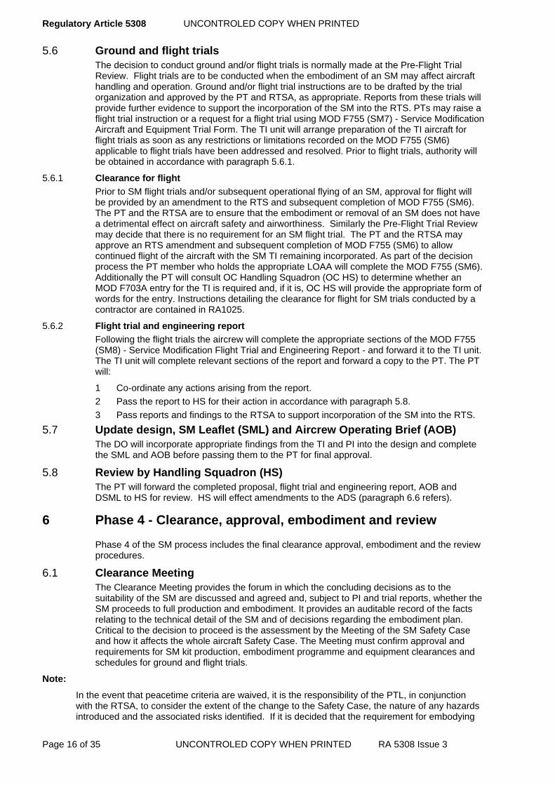
Regulatory Article 5308 UNCONTROLED COPY WHEN PRINTED
Page 16 of 35 UNCONTROLED COPY WHEN PRINTED RA 5308 Issue 3
5.6 Ground and flight trials The decision to conduct ground and/or flight trials is normally made at the Pre-Flight Trial Review. Flight trials are to be conducted when the embodiment of an SM may affect aircraft handling and operation. Ground and/or flight trial instructions are to be drafted by the trial organization and approved by the PT and RTSA, as appropriate. Reports from these trials will provide further evidence to support the incorporation of the SM into the RTS. PTs may raise a flight trial instruction or a request for a flight trial using MOD F755 (SM7) - Service Modification Aircraft and Equipment Trial Form. The TI unit will arrange preparation of the TI aircraft for flight trials as soon as any restrictions or limitations recorded on the MOD F755 (SM6) applicable to flight trials have been addressed and resolved. Prior to flight trials, authority will be obtained in accordance with paragraph 5.6.1.
5.6.1 Clearance for flight
Prior to SM flight trials and/or subsequent operational flying of an SM, approval for flight will be provided by an amendment to the RTS and subsequent completion of MOD F755 (SM6). The PT and the RTSA are to ensure that the embodiment or removal of an SM does not have a detrimental effect on aircraft safety and airworthiness. Similarly the Pre-Flight Trial Review may decide that there is no requirement for an SM flight trial. The PT and the RTSA may approve an RTS amendment and subsequent completion of MOD F755 (SM6) to allow continued flight of the aircraft with the SM TI remaining incorporated. As part of the decision process the PT member who holds the appropriate LOAA will complete the MOD F755 (SM6). Additionally the PT will consult OC Handling Squadron (OC HS) to determine whether an MOD F703A entry for the TI is required and, if it is, OC HS will provide the appropriate form of words for the entry. Instructions detailing the clearance for flight for SM trials conducted by a contractor are contained in RA1025.
5.6.2 Flight trial and engineering report
Following the flight trials the aircrew will complete the appropriate sections of the MOD F755 (SM8) - Service Modification Flight Trial and Engineering Report - and forward it to the TI unit. The TI unit will complete relevant sections of the report and forward a copy to the PT. The PT will:
1 Co-ordinate any actions arising from the report. 2 Pass the report to HS for their action in accordance with paragraph 5.8. 3 Pass reports and findings to the RTSA to support incorporation of the SM into the RTS.
5.7 Update design, SM Leaflet (SML) and Aircrew Operating Brief (AOB) The DO will incorporate appropriate findings from the TI and PI into the design and complete the SML and AOB before passing them to the PT for final approval.
5.8 Review by Handling Squadron (HS) The PT will forward the completed proposal, flight trial and engineering report, AOB and DSML to HS for review. HS will effect amendments to the ADS (paragraph 6.6 refers).
6 Phase 4 - Clearance, approval, embodiment and review
Phase 4 of the SM process includes the final clearance approval, embodiment and the review procedures.
6.1 Clearance Meeting The Clearance Meeting provides the forum in which the concluding decisions as to the suitability of the SM are discussed and agreed and, subject to PI and trial reports, whether the SM proceeds to full production and embodiment. It provides an auditable record of the facts relating to the technical detail of the SM and of decisions regarding the embodiment plan. Critical to the decision to proceed is the assessment by the Meeting of the SM Safety Case and how it affects the whole aircraft Safety Case. The Meeting must confirm approval and requirements for SM kit production, embodiment programme and equipment clearances and schedules for ground and flight trials.
Note:
In the event that peacetime criteria are waived, it is the responsibility of the PTL, in conjunction with the RTSA, to consider the extent of the change to the Safety Case, the nature of any hazards introduced and the associated risks identified. If it is decided that the requirement for embodying

UNCONTROLED COPY WHEN PRINTED Regulatory Article 5308
RA 5308 Issue 3 UNCONTROLED COPY WHEN PRINTED Page 17 of 35
the SM outweighs the risks identified, the PT member who holds the appropriate LOAA will authorize the SM and append an appropriate statement on the MOD F755 (SM9) - Service Modification Clearance Certificate.
6.1.1 Record of proceedings
The proceedings of the Clearance Meeting are to be recorded in the form of minutes in accordance with JSP 101 (see References) and by completion of MOD F755 (SM9) by the PT member who holds the appropriate LOAA. Proposed attendees, agenda items and guidance notes are provided at paragraph 11 of this Annex.
6.2 SML approval, publication and distribution Following confirmation of operational flight clearances, acceptance of the incorporation of the SM into the RTS by the RTSA and satisfactory resolution of any outstanding issues, the PT member who holds the appropriate LOAA will authorize the issue of the SML on the F755 (SM9). PTs are to distribute SMLs in accordance with MOD F755 (SM9).
6.3 Highlighting SM effects on handling and operation For SMs affecting the handling or operation of an aircraft or its equipment, refer to RA5312.
6.4 Embodiment 6.4.1 General
The SM embodiment programme will be finalised between the PT and appropriate agencies at the Clearance Meeting. The PT will arrange for the provision of sufficient modification kits to supply embodiment programmes at agreed maintenance organizations, including aircraft in storage, as appropriate. To achieve the programme targets, PTs may liaise with FLCs to encourage embodiment on an opportunity basis through a modification campaign within a Forward organization and the PT might do likewise for Depth organizations.
6.4.2 Embodiment outside user units
Whenever an SM is required to be embodied in an aircraft or equipment other than those at a Forward organization or outside FLC control, the PT is responsible for deciding upon and making any necessary arrangements, additional to those in this publication, for the safe and correct embodiment of the SM.
6.4.3 Post-embodiment fault reporting
Any in-service faults with the embodied SM installation are to be reported to the PT through the MOD Form 760 fault reporting system in accordance with MAP Chapter 7.5.1.
6.5 Update of design records To maintain configuration control, the PT is responsible for ensuring that an SM is incorporated into the aircraft or equipment's design records. Design records can be changed in one of two ways depending on the nature of the SM and the wishes of the PT.
6.5.1 DO cover modification
If the SM will be incorporated into the build standard of any materiel delivered by the Original Equipment Manufacturer (OEM), a DO cover modification is required in accordance with RA5313.
6.5.2 Amendment
If the PT does not require the SM to be incorporated in materiel delivered by the OEM, and an amendment to the design records is acceptable, it may be sufficient for the DO SM index and drawings to be permanently annotated with the SM number.
6.6 Amend Aircraft Document Set (ADS) The PT will incorporate the SM into the Topic 2(N/A/R)2 in accordance with MAP Chapter 8.4 and submit Service Amendment Leaflets to update Technical Information in accordance with MAP Chapter 8.2.2. RA1310 provides a list of publications in the ADS that are probably affected and RA1370 provides detailed instructions on authorities and responsibilities for amendments to the ADS. PTs are to identify and amend any additional type-specific publications that make up their ADS, as appropriate.
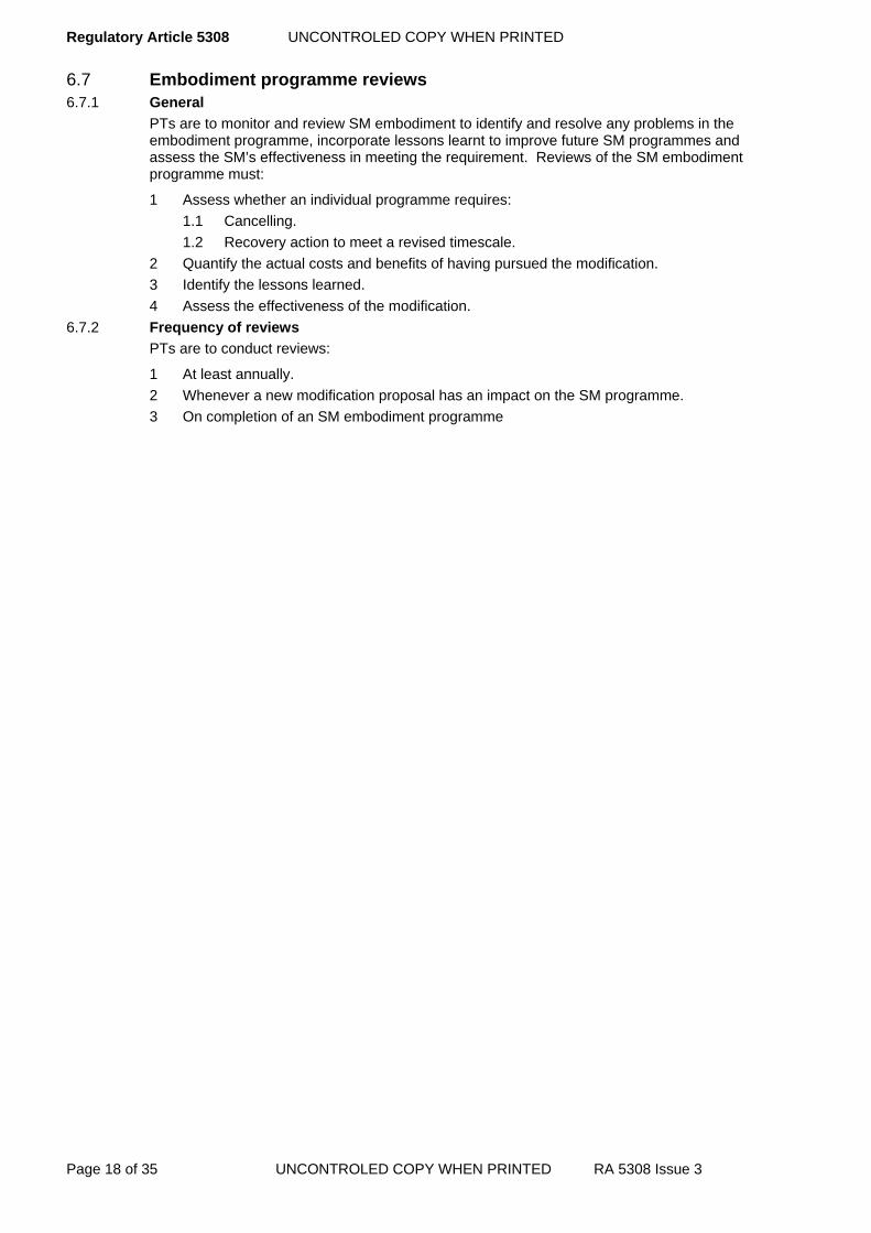
Regulatory Article 5308 UNCONTROLED COPY WHEN PRINTED
Page 18 of 35 UNCONTROLED COPY WHEN PRINTED RA 5308 Issue 3
6.7 Embodiment programme reviews 6.7.1 General
PTs are to monitor and review SM embodiment to identify and resolve any problems in the embodiment programme, incorporate lessons learnt to improve future SM programmes and assess the SM’s effectiveness in meeting the requirement. Reviews of the SM embodiment programme must:
1 Assess whether an individual programme requires: 1.1 Cancelling. 1.2 Recovery action to meet a revised timescale.
2 Quantify the actual costs and benefits of having pursued the modification. 3 Identify the lessons learned. 4 Assess the effectiveness of the modification.
6.7.2 Frequency of reviews
PTs are to conduct reviews:
1 At least annually. 2 Whenever a new modification proposal has an impact on the SM programme. 3 On completion of an SM embodiment programme

UNCONTROLED COPY WHEN PRINTED Regulatory Article 5308
RA 5308 Issue 3 UNCONTROLED COPY WHEN PRINTED Page 19 of 35
, MOD
& Industry F755(SM1)
PTIdentify Feasible Solution
PTSafety & Support
QuestionnaireF755(SM2)
FLC, ECC and RTSA
to comment on proposalF755(SM1)
Is SMBest Route?
Accept Proposal?
Yes
No
Yes
OriginatorSM ProposalF755(SM1)
PT Consider Designer Mod ( DM ) RA5313
PTReject Proposal -
annotate
F755(SM1)
PT Complete F755(SM1)
Register Proposal and raiseSM Proposal Progression
F755(SM4)
PTInform Originator
NO
DO DAOS Approved
PT Select/Task a DO
Design & Develope DSML, Safety Case, Certificates of Design ,
Removal InstructionsF755(SM4)
PTAssure DO Competence No
PTReview SM Proposal
Accept SM Proposal
Consider - DO support , Designer
advice or waiver . Exemption to comply with designer or Specialist advice .
Yes
DO Amplification of Proposal F 755 ( SM3)
PTFeasibility Study
Initiation Phase
DM Route ?
Yes
No
PTReject SM Proposal
Instruct Designer to remove annotation from Design
Records
No
PTConsider Designer Modification (DM) Chap 10.3 refers
Yes
PTInform Originator and SM
Proposal Recipients Page 2
Designer Annotate Design Records
Consider consultation withEquipment PTs

Regulatory Article 5308 UNCONTROLED COPY WHEN PRINTED
Page 20 of 35 UNCONTROLED COPY WHEN PRINTED RA 5308 Issue 3
Page 1
PT Initiation Meeting Raise F755(SM5)
Determine strategy and support requirements for SM development. PT/RTSA expected to agree whatevidence is required.
Initiation Certificate F755(SM5) to be
issued
RTSA to review and agree proposal.PT Sponsorship/financial approval for design, production and embodiment of SM. Trial Unit nominated/authorized. Consider requirement to conduct Proof Installation (PI)
SM DO To review Safety
Assessment.F755(SM6)
PT/RTSASafety Case Review, Flight
Trial Clearance/Clearance forFlight and RTS Approval
F755(SM6)
Flight TrialsRequired
PT Raise Trial Instruction or
F755(SM7)
Yes
PT Raise SM Clearance
Certificate F755(SM9)
No
Flight Trial UnitFlight Trial Aircrew
Engineering and HandlingSqn report. F755(SM8)
PTSML & AOB Approval, Publication & Distribution. Highlight SM effects on Handling/Operation. SM embodimentprogrammme finalized. Configuration Control - ensure that SM is incorporated into aircraft/equipment design
records. Issue a Designer cover modification if the OEM has been affected or amend ADS - incorporate into Topic2(N/A/R)2. Review Embodiment Programme. F755(SM9)
DO SM Development
PT
Raise SM TI, Engineering Installation & PT Clearance Certificate F755(SM6)
TI Unit Carryout TI and produce Post -TI
report - To include any Post -Installation Ground Tests as required
by TI. F755(SM6)
PTSM TI may require its periodicty
reviewed - to Extend or to Transfer.F755(SM10)<

UNCONTROLED COPY WHEN PRINTED Regulatory Article 5308
RA 5308 Issue 3 UNCONTROLED COPY WHEN PRINTED Page 21 of 35
7 Subsequent changes to an SM Once SM drawings are sealed and issued for use with the SML, the design and installation may only be modified or removed by an approved, properly controlled formal procedure. The options available to the PT are detailed below.
7.1 Extension or transfer of embodiment 7.1.1 General
There are occasions when an SM may be fitted for a specified period or event. If it becomes necessary to extend the duration of such an SM beyond the authorized period, or transfer embodiment to another airframe or equipment, the PT will carry out and document a formal review of the SM prior to authorising the change. This includes:
1 Obtaining stakeholder approval. 2 Verifying the technical content of the SM with reference to equipment PTs. 3 Considering the effects on in-service support for the SM. 4 Undertaking a complete check of Technical Information to ensure that there is an
accurate cross-reference between the ADS and any special procedures or warnings. 5 Reviewing the SM Safety Case and whole aircraft Safety Case. 6 Verifying the continued validity of the weapons safety certificate. 7 Obtaining approval from the RTSA to ensure the continued validity of the RTS 8 Verifying with HS and FLCs that operating instructions are adequately covered. 9 Ensuring that relevant clearances remain valid. 10 Ensuring that CM records are updated. 11 Checking SM compatibility with any additional/alternative airframes or equipment
selected. 7.1.2 Authorizing an extension or transfer of embodiment
When a PT grants an authorization for an extension or transfer of embodiment, the change will be:
1 Recorded on the MOD F755(SM10) - Service Modification Authority for Extension or Transfer - stating the number of aircraft or equipments affected, the authorized duration, RTS references and validity period and any other conditions and limitations imposed, and copied to all relevant Ship/Stn/Units, staffs and RTSA.
2 Recorded in the SM register. 7.2 Changes to, or cancellation of, an SM
At times it may be necessary to change or cancel an SM. An SM can only be superseded by a new SM or DM; however, an SM may be cancelled whenever its purpose is fulfilled, it is superseded, or the original requirement no longer exists. When there is a requirement to change an SM, and the required change does not meet the criteria of an amendment as described in paragraph 7.3, or the cancelled SM will be removed and removal instructions were not provided with the SML, the PT will generate a new SM as follows:
1 Issue and record in the SM register a new SML under the existing serial number transcribed with an oblique followed by a letter suffix (eg SM/TOR/XXX/A)
2 Follow the SM procedure and all associated activities; paragraph 2 refers. The PT will establish the course of action to progress the SM Change or Cancellation proposal. The MOD F755(SM11) - Service Modification Change/Cancellation Proposal - will be used to assist in managing the proposal. Where the SM has already been embodied, consider any rework requirements to bring the original SM to the latest standard.
3 Authorize the SM Change or Cancellation proposal as per paragraph 2. This will be done in consultation with the RTSA.
4 Cancel the previous SML. If the requirement to change an SM is urgent, the PT may initiate Special Instruction (Technical) (SI(T)) action in accordance with RA5405. Where the SI(T) is drafted by any organization other than the original DO, the PT will forward a copy of the draft to the DO for comment. Invariably, the PT must request the DO to prepare the SI(T) on its behalf. PTs are to have a robust system in place to monitor and proactively manage SI(T) to ensure that they remain extant for the minimum practical period in accordance with RA5405.

Regulatory Article 5308 UNCONTROLED COPY WHEN PRINTED
Page 22 of 35 UNCONTROLED COPY WHEN PRINTED RA 5308 Issue 3
7.3 Amendments to an SML PTs may authorize amendments to an SML for textual errors, or to matters that do not affect the work content of the leaflet and do not require retrospective action to be taken on the aircraft or equipment. In such instances, the PT will raise an MOD F755 (SM12) - SM Amendment Proposal. PTs are to approve the process for authorizing and issuing amendments to SMLs that may include printed form or electronic format. Amendments to SMLs are to comply with the format standard as required by JSP 182.
8 Partial embodiment or inhibiting of an SM There will be occasions when an SM will be partially embodied, or it will be fully embodied but its operation will need to be inhibited. In such instances, the PT will ensure that all envisaged configurations of the SM are:
1 Clearly defined. 2 Addressed in the SM and whole aircraft Safety Case. 3 Cleared for flight in the RTS. 4 Recorded in the SM documentation, particularly the SML and ADS where applicable,
including: 4.1 Removal and fitting instructions. 4.2 Inhibiting, reactivation and testing procedures. 4.3 Safety and warning notices. 4.4 MOD F703 series of forms
9 Responsibilities The following sub-paragraphs detail the responsibilities (non-exhaustive list) associated with an SM.
9.1 Release to Service Authority (RTSA) The RTSA is responsible for:
1 Providing advice on how the SM proposal is likely to impact on flying limitations, emergency procedures, effects on other systems and any other operating issues.
2 Assessing modifications from the operational airworthiness aspect. 3 Reviewing modifications and advising on effects on the aircraft flying and handling
characteristics and amending the RTS accordingly. 4 Providing the authorisation for flight trial or clearance for flight upon SM embodiment.
9.2 Front Line Command (FLC) The FLC is responsible for:
1 Providing appropriate advice and comments on SM proposals and embodiment plans. 2 Nominating Ship/Stn/Units to assist in SM development, trials and embodiment as
agreed with the PT. 9.3 Aircraft PT
The aircraft PT is responsible for:
1 Centrally managing the overall SM process whilst contracting out elements of the process to suitably competent organizations that offer a range of services from proposal progression to end-to-end design, delivery and embodiment.
2 Co-ordinating the activities of the agencies preparing the SM, including equipment PTs as appropriate
3 Obtaining an SM Safety Case and integrating it into the whole aircraft Safety Case. 4 Arranging for the integration of equipment PT-developed modifications. 5 Undertaking technical editing of the DSML. 6 Ensuring that SM proposals, DSMLs and flight trial reports are copied to HS. 7 Ensuring that equipment PTs, DOs, OEMs or TI units are tasked, where appropriate, to
provide HS with draft source material on the operation and handling of the modified aircraft to enable HS to produce appropriate amendments to the ADS.

UNCONTROLED COPY WHEN PRINTED Regulatory Article 5308
RA 5308 Issue 3 UNCONTROLED COPY WHEN PRINTED Page 23 of 35
8 Ensuring that information on the operational and maintenance effects of the SM is included in the RTS, SOIU, ODM, associated modification leaflets and the ADS.
9 Ensuring that the RTSA has sufficient evidence to authorize SM trials and operational flying.
10 Ensuring that SM trials and SM operational flying are authorized before flight. 11 Arranging for the production and maintenance of all appropriate SM documentation and
drawings, unless a DM supersedes the SM. It is desirable that SM drawings use the commercial practice of the DO to reduce subsequent rework, which may be required for a cover modification.
12 Maintaining a register of SMs. 13 Ensuring that a master copy of the SML is retained for the life of the aircraft. 14 Ensuring that equipment or wiring installed for SM trial purposes has an agreed standard
of external markings, or banding, to clearly identify it. 15 Reviewing and monitoring the modification embodiment programme. 16 Arranging for DO cover modification action as appropriate.
9.4 Equipment PTs Equipment PT are responsible for:
1 Alerting appropriate aircraft PTs when developing an SM that affects multiple platforms. 2 Furnishing data to aircraft PTs to assist with integrating equipment modifications into an
aircraft. 3 Commenting on SM proposals passed to them by an aircraft PT
9.5 Handling Squadron (HS) HS is responsible for:
1 The standards, quality and fitness for purpose of aircraft handling material, including Aircrew Manuals, Flight Test Schedules and Flight Reference Cards.
2 Ensuring that information on SMs that affect aircraft operations and handling is presented to aircrew in a timely manner.
10 Guidance on Initiation Meetings 10.1 Attendees
The following is a suggested list of likely stakeholders/contributors in the configuration change process. As a minimum it is mandatory for those stakeholders/contributors marked with an asterisk to attend:
1 Platform PT. * 2 RTSA. * 3 DO. * 4 Publication Organization. 5 TI unit and associated FLC. 6 Equipment Sponsor. 7 Equipment PT. 8 FLCs or unit as appropriate, ie user, engineering and operational representatives. * 9 DG Weapons. 10 HS. 11 Flight Simulators and Synthetic Trainers PT. 12 Testing organizations, contractors and external agencies. 13 Centre of Aviation Medicine. 14 Defence Security Standards Organization (DSSO).
10.2 Initiation Meeting The Initiation Meeting will cover the following aspects:
1 An understanding of the requirements by the stakeholders. 2 Identification of possible outline solutions.

Regulatory Article 5308 UNCONTROLED COPY WHEN PRINTED
Page 24 of 35 UNCONTROLED COPY WHEN PRINTED RA 5308 Issue 3
3 Suitability, viability and benefits of the proposed solution. (A DM, rather than an SM, will be pursued? Do other PDS activities, either in progress or planned, affect the status of the proposed SM and will it adversely affect other modification proposals or intentions? Do any proposals currently being considered, or progressed, by other PTs address a similar requirement?)
4 Potential hazards and likely implications for the Safety Case. (Is the effect of the proposed SM acceptable to the airworthiness, structure, reliability, maintainability and performance of the equipment being modified, or any associated equipment or system? Does the proposal, SSQ and DSML reveal any serious safety implications?)
5 Effects on the RTS. 6 Compatibility with associated equipment and implications on armament/electrical
systems and EMC. 7 Requirements for independent assessment. 8 Production and supply of SM kits. 9 Nomination of a TI unit. 10 Draft embodiment plan. 11 Resources for TIs, PIs and embodiment. 12 Through-life support and costs.
10.3 Meeting agenda and minutes The following table details aspects of the proposal that the PT must consider before approving the design. All items are to be addressed during the Meeting. Each item will be supported by an appropriate decision or statement in the minutes.
Table 1. Items for Initiation Meeting Minutes Item Discussion and Decisions
1. Design Consider the design in detail, with particular reference to the outline design, SSQ, supporting drawings and aircraft mock-up wherever possible. Record any changes from the initial proposed design as reservations on the initiation certificate. Record any other peripheral design considerations in the minutes.
2. Airworthiness and flight safety
The DO will advise the meeting on general aircraft safety aspects, including airworthiness and changes in weight and balance. If the SM is likely to interact with any flight safety-critical system, the PT will task a suitable organization to provide specialist advice during SM development and to carry out any subsequent testing.
3. Release to Service
Consider the effects of the SM on the RTS. The RTSA and PT are to discuss and agree the SM supporting evidence that will be needed for the RTSA to give approval for flight and operational clearances. Detailed regulations covering clearance for flight are contained in RA1300.
4. Certificates of Design
Confirm that Certificates of Design are available, or are being raised, for equipment introduced by the SM. Allocate responsibilities to the appropriate MOD specialist branch or, in the case of Service-designed and manufactured equipment, to the relevant Service sponsor. Certificates of Design, plus supporting documents, will need to be submitted to the PT for consideration and agreement of any limitations and exceptions.
5. Electrical system and EMC
With the assistance of specialists, assess the need for electrical system and EMC testing and task specialist organizations as appropriate. Def Stan 59-411 details the specification of contractual requirements for EMC testing.
6. Explosive safety An appropriate specialist organization will make a statement about the likely effect of the SM on aircraft that contain or carry explosive devices. The PT will initiate any necessary tasking for provision of specialist advice during SM development and for carrying out any subsequent testing.
7. TEMPEST clearance
Assess the need for TEMPEST clearance and make arrangements for testing the TI aircraft as required.
8. Security Accreditation
Assess the impact the modification will have on security issues, ie any increase in the Protective Marking of data processed/stored in equipment modified/introduced by this modification. Advice can be sought from the platform Security Accreditation Co-ordinator or DSSO.

UNCONTROLED COPY WHEN PRINTED Regulatory Article 5308
RA 5308 Issue 3 UNCONTROLED COPY WHEN PRINTED Page 25 of 35
Item Discussion and Decisions
9. Portability Assess whether the SM is likely to affect in any way the cargo-carrying or handling facilities of a transport aircraft. If the aircraft is itself air portable, consider any aspect of the SM that is likely to affect this capability. The aircraft PT will notify the Joint Air Delivery Test and Evaluation Unit of any relevant factors.
10. Documentation Note any departures from the standard of SM documentation illustrated in RA1300. The aircraft PT is responsible for forwarding proposals for flight test schedule amendments to Handling Squadron (HS).
11. Aircrew Operating Brief
Task the DO with producing a draft Aircrew Operating Brief (AOB).
12. Provisional on-aircraft servicing information
There will usually be a need to make engineering information on the SM installation available to user units in advance of formal publication amendments. Task the TI Unit with preparing the necessary information for issue to the aircraft PT prior to the Clearance Meeting. The aircraft PT is responsible for arranging promulgation of this information to user units. Promulgation may initially be in the form of Service Amendment Leaflets.
13. Equipment approval
Request equipment PTs to act as approving authority for any items of equipment required for the SM, which are as yet unapproved for the particular application concerned. If a PT is unable to accept this responsibility, nominate one to act as approving officer for the equipment and make the necessary submissions. When the SM introduces newly developed equipment, the PT will approve its use, initially for limited applicability as part of the SM installation. A further full approval will be made on satisfactory completion of flight trials.
14. Equipment clearance
Aircraft equipment clearance is required for a part if: - Its design or use is new to the MOD. - It is, or is derived from, an existing approved part, but will be used for a function or in an application different from that for which the part was originally approved. The PT will seek aircraft equipment clearance for the use of unapproved parts. This requirement may be waived if the part has no effect on the Safety Case and the PT is willing to accept full responsibility for its intended use.
15. Trial Installation If a TI is required, confirm the proposed dates of the TI and make all arrangements for positioning the aircraft at the TI unit. Identify any special arrangements for preparing and recovering the aircraft and allocate responsibilities. The PT will identify items that require special provisioning action and ensure that these items are available for the TI. Identify the need for continuing advice and assistance from aircraft and equipment contractors. The PT will arrange for support from the equipment DO or post-design support contractors.
16. Installation testing
Stipulate the procedures to be used for testing the SM TI. The testing, which will also be applicable to the PI, will be based on the advice given by the DO responsible for the equipment being installed.
17. Resources Consider the resource requirements for each stage of the SM process. Where non-Stn/Ship/Unit personnel may be employed, they are to be managed in accordance with MAP Chapter 4.8.2.
18. Ground and/or flight trials
Decide requirement and agree provisional dates for trials to take place. Additional trials to assess the operational performance of the SM installation may be required and arrangements for these are the responsibility of the FLC. Task the TI unit with preparing lists of flight trial requirements and forwarding them to the PT for incorporation into the trials instruction. Consult with OC HS to determine requirement for an MOD F703A entry and the appropriate wording. Allocate responsibilities for conducting ground/ flight trials. Flight trials are to be carried out on the TI aircraft to all or part of the aircraft Topic 5M, supplemented by the requirements of the TI unit and as detailed in the trials instruction. Procedures for clearance for flight and authorities for the RTS are contained in RA1300.
19. Ongoing support
Consider the need to examine the implications of SM embodiment on factors such as spares, test equipment, maintenance facilities, servicing schedules, personnel health/safety and aircraft ground handling.

Regulatory Article 5308 UNCONTROLED COPY WHEN PRINTED
Page 26 of 35 UNCONTROLED COPY WHEN PRINTED RA 5308 Issue 3
Item Discussion and Decisions
20. Provisioning Note any items for which special provisioning action may be required, but only in exceptional circumstances would it be appropriate to initiate provisioning action in advance of the Clearance Meeting.
21. Fleet Embodiment
Record the target date for commencing fleet embodiment and details of the planned embodiment programme.
22. DO cover modification
Consider the requirement and likely cost of a cover modification. Cost estimates for a cover modification are to be included in the SM cost estimates. Further information regarding DO cover modifications can be found in RA5313.
23. Any other business
Consider any factors relevant to the SM not covered by the foregoing paragraphs.
11.3.1 Distribution
Copies of the Meeting minutes and Initiation Certificate are to be sent to each of the attendees and all other stakeholders who were not in attendance.
11 Guidance on Pre-Flight Review and Clearance Meetings 11.1 Attendees
The Pre-Flight Review and Clearance Meetings must include all key stakeholders/contributors in the configuration change process. A list of likely attendees is provided at paragraph 10.1.
11.2 Meeting agenda and minutes The following table contains mandatory items for the Review and Meeting agendas. Each item will be supported by an appropriate decision or statement in the minutes. Items marked with an * may not be applicable to the Pre-Flight Review.
Table 2. Items for Pre-Flight Review and Clearance Meeting Minutes. Item Discussion and Decisions
1. Outstanding actions from the Initiation Meeting
Review the outstanding actions; however, their discussion may be included under subsequent agenda items if appropriate.
2. Design Consider the detailed design of the SM, with reference to the TI aircraft and the TI clearance brief. List any further changes to the design as reservations on the clearance certificate, classified as either requiring action before the flight trial or before the final issue of SM documentation. Record any other peripheral design considerations
3. Removal instructions *
Confirm whether or not SM removal instructions are needed.
4. Safety Case Review the SM Safety Case, consider its effects on the whole aircraft Safety Case and confirm that all actions essential to the safety of the aircraft have been carried out; in particular that: 1 All necessary DO clearances have been given and recorded. 2 EMC testing has been carried out successfully, or is being addressed. 3 TEMPEST clearance has been addressed. 4 Confirmation of armament safety is available, or detailed investigations of
these aspects are being addressed. Consider the integration of the SM Safety Case into the whole aircraft Safety Case.
5. Certificates of Design / Equipment Clearances
Confirm that Certificates of Design and Equipment Clearances are available for all equipment introduced by the SM.
6. Release to Service
The RTSA will confirm that sufficient evidence exists to support the SM’s RTS. Record the RTSA’s comments in the minutes.

UNCONTROLED COPY WHEN PRINTED Regulatory Article 5308
RA 5308 Issue 3 UNCONTROLED COPY WHEN PRINTED Page 27 of 35
Item Discussion and Decisions
7. Clearance for flight
Record the agreement for flight trials of the TI aircraft, or record the authority to operate the aircraft with the TI fitted when flight trials are not deemed necessary, subject to clearance of the appropriate reservations listed on the clearance certificate. Alternatively, record those actions that are to be carried out before the aircraft can be released for flight trials. If doubts about EMC or armament safety remain to be resolved, the aircraft will be cleared for the delivery flight only, with any equipment introduced by the SM switched off or disabled where applicable. Procedures for clearance for flight trials and authorities for RTS are contained in RA1300 and RA 5202.
8. Aircrew Operating Brief
Confirm details for producing and authorising the Aircrew Operators Brief (AOB) for issue to aircrew prior to flight trials.
9. Flight trials Confirm the arrangements made for RTS trials and any other trials considered necessary and detail the continuing actions required to implement them.
10. Proof Installation *
If there is a requirement for a PI, allocate provisional dates and agree arrangements for positioning the aircraft at the PI unit. Allocate responsibilities for any special PI provisioning action.
11. In-service support *
Review the in-service support requirements.
12. Documentation* Review the content of the AOB and the provisional on-aircraft servicing information produced by the TI unit. Detail any amendments required. The minutes are to contain a statement of the requirement for distributing copies of SM drawings and the SML, and state the target date for issue. Handling Sqn (HS) will advise on the wording of an MOD Form 703A entry, which will be included in the SML. The minutes must also state the change requirements to associated electronic information systems, including structure, online forms, asset tracking and scheduled maintenance.
13. Production considerations *
Confirm the arrangements for fleet embodiment and any actions for provisioning long lead-time items deemed necessary to ensure that production timescales are met. Set a provisional date for the first production-planning meeting.
14. Any other business
Consider any factors relevant to the continuing development and embodiment of the SM, including the embodiment programme, not covered by the foregoing paragraphs.
11.2.1 Distribution
Copies of the Review/Meeting minutes and clearance certificate are to be sent to each of the attendees and all other stakeholders who were not in attendance
12 Guidance on drafting an SML The following table details the mandatory items for inclusion in an SML and provides guidance notes for drafting an SML. The layout will accord with JSP 182, unless otherwise directed by the PTL.
Table 3. SML Content and Guidance Notes
MAIN EQUIPMENT (Aircraft Type and Mark) SM No
Title of Service Modification
1 INTRODUCTION Insert here a brief statement of why the modification is introduced, what it is and how it achieves the requirement. Insert the following sub-paragraphs (1), (2), (3) and (4) as appropriate:

Regulatory Article 5308 UNCONTROLED COPY WHEN PRINTED
Page 28 of 35 UNCONTROLED COPY WHEN PRINTED RA 5308 Issue 3
MAIN EQUIPMENT (Aircraft Type and Mark) SM No
Title of Service Modification
(1) This modification supersedes/partially supersedes/is satisfied by the work called for by Mod No *** /Service Modification No *** /Technical Instruction ***.
or, if appropriate: (1) This modification does not supersede, partially supersede or satisfy the work called for by any other modification, Service Modification, or Technical Instruction.
(2) This modification is the cover/complementary modification to component Mod No ***.
or, if appropriate: (2) The cover/complementary airframe modification to this modification is Mod No ***.
(3) This modification is essentially connected with Mod No ***. If that work is not already embodied it will be effected concurrently.
(4) This modification is applicable only if Mod No *** is/is not already embodied.
EMBODIMENT State the extent of application of the SM to the type of equipment concerned and include any special embodiment instructions issued by the PT.
2
Approximate time required for embodiment
State the estimated man-hours to modify one equipment, including any local manufacture. Include separately the man-hours for stripping, re-assembly and testing.
3 DRAWINGS REQUIRED
State Drawing/Figure Numbers incorporated in this leaflet and/or list the drawing number and titles of drawings that are to be demanded. Provide details of how and where to demand drawings as applicable. Note: In general, drawings must be incorporated in leaflets and be of the simple line diagram or sketch type, to engineering drawing standard. Drawings or sketches submitted with a proposal must be suitable for reproduction and sufficiently large for a 2 to 1 reduction. For standard A4 size, the maximum size of the printed illustration (including captions, sheet number, fig number, title and security markings) is 260 mm x 165 mm. Line diagrams or sketches to be used as working drawings are to have all detail large enough to be easily interpreted. Photographs must only be used to complement drawings.
4 PARTS AND SPECIAL TOOLS REQUIRED
List the parts and any special tools required by Management code/ Stock No, Nomenclature and Quantity. The quantity of parts will be that number required to embody the SM on one equipment. Describe any special arrangements for supplying the parts and tools listed. Detail all hazardous substances used during embodiment, referring to JSP 515; list under the following headings: Reference No, Part No and Nomenclature. State the details of any Special Tools and/or Test Equipment required. List details of any affected spares under the following headings: 5 MODIFICATION
OF SPARES Ref No Part No Nomenclature Qty Class of Equipment
6 CHANGE OF
REFERENCE, PART AND ASSEMBLY NUMBERS
List details of any changes.
7 SEQUENCE OF OPERATIONS
(The following is a typical sequence of operations)
Safety Precautions Specify the safety precautions that are to be taken. The leaflet will contain a specific statement detailing the Health and Safety requirements (including COSHH).

UNCONTROLED COPY WHEN PRINTED Regulatory Article 5308
RA 5308 Issue 3 UNCONTROLED COPY WHEN PRINTED Page 29 of 35
MAIN EQUIPMENT (Aircraft Type and Mark) SM No
Title of Service Modification
Installation Detail the sequence of operations, which must be practically proven if possible, required to complete the installation. Each individual operation will be separately paragraphed. List any changes to fuse and circuit breaker indexes and identify stage checks. If physical marking of the equipment will be a recording requirement, include the appropriate work instructions here.
Removal Detail the sequence of operations required, which must be practically proven if possible, to remove the SM. Each individual operation will be separately paragraphed.
8 Detail any Operating Instructions/Procedures applicable to the installed SM and/or refer to any existing instructions.
State whether any special tests or checks are required after embodying the SM. A selection of typical entries is provided. Others may be added if considered necessary.
SPECIAL TESTS AFTER EMBODIMENT
1 When the modification has been embodied and inspected, do the following special tests:
… …etc
2 When this modification has been embodied and inspected, do functional tests of all systems that have been disturbed for the purpose of embodying this modification, in accordance with current testing instructions. 3 As the embodiment of this modification involves disturbance of the **** system, an independent check of the system will be made in accordance with MAP Chapter 6.10. 4 A flight trial is/is not required to prove satisfactory installation of the SM. 5 No special testing is required after embodying this modification but any other appropriate associated testing will be done. **** Detail which system(s).
9 RECORDING ACTION
When this modification has been embodied and inspected in accordance with current authorized procedures, the relevant entries are to be made in the appropriate aircraft/component records. Explicit instructions are to be given concerning which MOD Form 700 series will be used for certifying embodiment of the SM and any further documentation that might be needed for particular requirements such as those indicated below: State any other recording action necessary. Permanent recording of the SM – by entry in nominated engineering record cards and, if appropriate, by physical marking of the equipment. Notifying aircrew – by entry of a specific statement regarding the need for an MOD Form 703A entry, detailing the wording of that statement. Certifying application of the SM to spare or stored equipment by entering a specified statement on the Engineering Record Card. Recording where necessary “modify after issue and before use” on the equipment label. Completing information system recording requirements, for SM configuration management. Any other recording requirements.
10 DISPOSAL OF REDUNDANT PARTS
List and state the disposal action for all parts removed and not reinstalled as a result of the SM under the following headings:
Ref No, Part No, Nomenclature, Qty, Class of Equipment & Disposal.
11 EFFECT ON WEIGHT AND MOMENT
Detail the effect of the SM on the weight and moment for recorded axes as follows: “Embodiment of SM *** causes a weight change of PLUS/MINUS ** lb/kg and a change of moment of PLUS/MINUS ** lb in/kg m.” (use appropriate units). Or state: “This SM has no effect on weight and moment.”
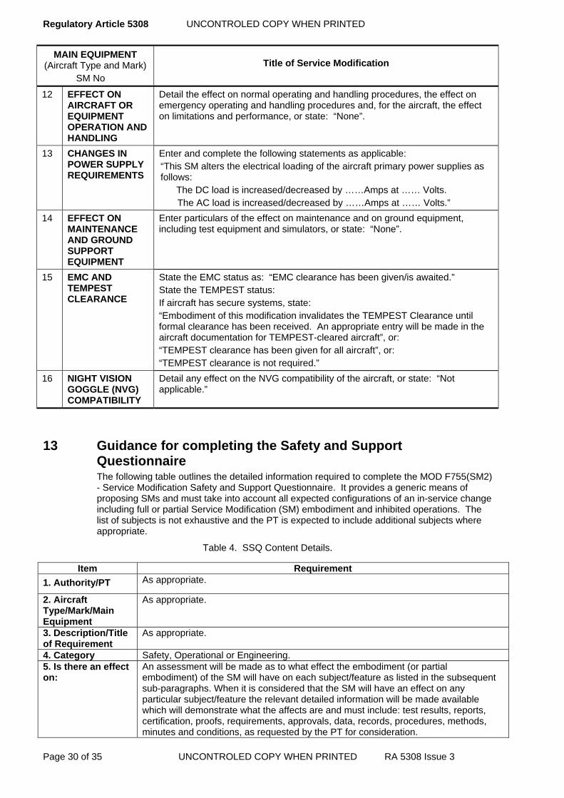
Regulatory Article 5308 UNCONTROLED COPY WHEN PRINTED
Page 30 of 35 UNCONTROLED COPY WHEN PRINTED RA 5308 Issue 3
MAIN EQUIPMENT (Aircraft Type and Mark) SM No
Title of Service Modification
12 EFFECT ON AIRCRAFT OR EQUIPMENT OPERATION AND HANDLING
Detail the effect on normal operating and handling procedures, the effect on emergency operating and handling procedures and, for the aircraft, the effect on limitations and performance, or state: “None”.
13 CHANGES IN POWER SUPPLY REQUIREMENTS
Enter and complete the following statements as applicable: “This SM alters the electrical loading of the aircraft primary power supplies as follows: The DC load is increased/decreased by ……Amps at …… Volts. The AC load is increased/decreased by ……Amps at …… Volts.”
14 EFFECT ON MAINTENANCE AND GROUND SUPPORT EQUIPMENT
Enter particulars of the effect on maintenance and on ground equipment, including test equipment and simulators, or state: “None”.
15 EMC AND TEMPEST CLEARANCE
State the EMC status as: “EMC clearance has been given/is awaited.” State the TEMPEST status: If aircraft has secure systems, state: “Embodiment of this modification invalidates the TEMPEST Clearance until formal clearance has been received. An appropriate entry will be made in the aircraft documentation for TEMPEST-cleared aircraft”, or: “TEMPEST clearance has been given for all aircraft”, or: “TEMPEST clearance is not required.”
16 NIGHT VISION GOGGLE (NVG) COMPATIBILITY
Detail any effect on the NVG compatibility of the aircraft, or state: “Not applicable.”
13 Guidance for completing the Safety and Support Questionnaire The following table outlines the detailed information required to complete the MOD F755(SM2) - Service Modification Safety and Support Questionnaire. It provides a generic means of proposing SMs and must take into account all expected configurations of an in-service change including full or partial Service Modification (SM) embodiment and inhibited operations. The list of subjects is not exhaustive and the PT is expected to include additional subjects where appropriate.
Table 4. SSQ Content Details.
Item Requirement
1. Authority/PT As appropriate.
2. Aircraft Type/Mark/Main Equipment
As appropriate.
3. Description/Title of Requirement
As appropriate.
4. Category Safety, Operational or Engineering. 5. Is there an effect on:
An assessment will be made as to what effect the embodiment (or partial embodiment) of the SM will have on each subject/feature as listed in the subsequent sub-paragraphs. When it is considered that the SM will have an effect on any particular subject/feature the relevant detailed information will be made available which will demonstrate what the affects are and must include: test results, reports, certification, proofs, requirements, approvals, data, records, procedures, methods, minutes and conditions, as requested by the PT for consideration.

UNCONTROLED COPY WHEN PRINTED Regulatory Article 5308
RA 5308 Issue 3 UNCONTROLED COPY WHEN PRINTED Page 31 of 35
a. Airworthiness and flight safety. Provide an assessment on the effects of the proposed change(s) on Airworthiness and flight safety including:
(1). Safety Case - State the effects on the Safety Case, the required changes and associated actions. (2). Statement of Operational Intent and Usage - State the effects on the SOIU. If the SOIU is affected it will be updated accordingly. (3). Operating Data Manual - State the effects on the Operating Data Manual. (4). Release to Service - With the assistance of the RTS Authority state the effects on the RTS. (5). Certificates of Design - State if Certificates of Design are required. (6). Structural Integrity - State how the Structural Integrity (SI) is affected. If the effect either directly or indirectly alters the static strength, fatigue life or corrosion resistance of the primary structure then the PT will refer findings to an appropriate SI working group for specialist advice. (7). Structural classification - State the classification, reference numbers and nomenclature of the structure to which the modified equipment will be attached or the modification work will alter. (8). Material specification - State the material specifications, reference numbers, standard wire gauge and nomenclature of the modification structural parts, except where these are given in the drawings provided. (9). Heat treatment - State the heat treatments required during manufacture including a list of relevant publications and/or British Standards Institution leaflets. If heat treatment is not required, a statement can include “may be cold worked. (10). Environmental Control System - State the effects on the Environment Control System. (11). Aircrew safety and operating procedures - State the effects on the aircrew safety and operating procedures including changes of:
(a). Primary displays, equipment interfaces, aircraft assisted escape systems, ejection seat profiles, crew access or movements. (b). Normal or emergency operating procedures. (c). Maintenance schedules, test programmes, check lists or change of role procedures or other documentation. (d). Operational flight software. (e). Special Instructions - Technical (SI(T)).
(12). Aircrew health - State the effects on aircrew environment and health. Specialist advice will normally be sought from appropriate organizations like the Institute of Aviation Medicine. (13). Human Machine Interface - State the effects on the Human Machine Interface. (14). Performance and reliability - State the effects on the performance and reliability of:
(a). Performance and handling of the aircraft or its installed systems. (b). Reliability of the aircraft or its systems. (c). Equipment, fittings, connections or wiring disturbed during access. (d). Changes to operational flight software.
(15). Compatibility - State the effects on the: (a). Category of compatibility affected by material, explosives, chemicals and electromagnetic effects. (b). Heat loading or any other effect on aircraft environment. (c). External interfaces. (d). Changes to ground power supplies, test equipment or other ancillary equipment. (e). Compatibility in any respect to other systems in the aircraft, e.g. night vision system. (f). Hazards to ground personnel. (g). Compatibility with other modifications and SI(T)s applicable to the aircraft or associated ground power supplies, test equipment or other ancillary equipment. (h). Requirement for any existing equipment, fittings or wiring disturbed for access.
(16). Interchangeability - State how the physical or functional interchangeability of the component, equipment or system will be affected. Physical interchangeability is
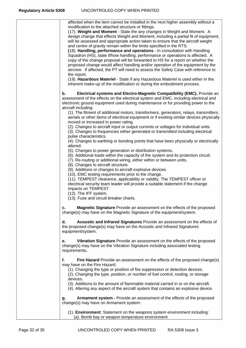
Regulatory Article 5308 UNCONTROLED COPY WHEN PRINTED
Page 32 of 35 UNCONTROLED COPY WHEN PRINTED RA 5308 Issue 3
affected when the item cannot be installed in the next higher assembly without a modification to the attached structure or fittings. (17). Weight and Moment - State the any changes in Weight and Moment. A design change that effects Weight and Moment, including a partial fit of equipment, will be assessed and appropriate action taken to ensure that the aircraft weight and centre of gravity remain within the limits specified in the RTS. (18). Handling, performance and operations - In consultation with Handling Squadron (HS), state if/how handling, performance or operations is affected. A copy of the change proposal will be forwarded to HS for a report on whether the proposed change would affect handling and/or operation of the equipment by the aircrew. If affected, the PT will need to assess the Safety Case with reference to the report. (19). Hazardous Materiel - State if any Hazardous Materiel is used either in the inherent make-up of the modification or during the embodiment process.
b. Electrical systems and Electro-Magnetic Compatibility (EMC). Provide an assessment of the effects on the electrical system and EMC, including electrical and electronic ground equipment used during maintenance or for providing power to the aircraft including:
(1). The fitment of additional motors, transformers, generators, relays, transmitters, aerials or other items of electrical equipment or if existing similar devices physically moved or increased in power rating. (2). Changes to aircraft input or output currents or voltages for individual units. (3). Changes to frequencies either generated or transmitted including electrical pulse characteristics. (4). Changes to earthing or bonding points that have been physically or electrically altered. (5). Changes to power generation or distribution systems. (6). Additional loads within the capacity of the system and its protection circuit. (7). Re-routing or additional wiring, either within or between units. (8). Changes to aircraft structure. (9). Additions or changes to aircraft explosive devices. (10). EMC testing requirements prior to the change. (11). TEMPEST clearance, applicability or validity. The TEMPEST officer or electrical security team leader will provide a suitable statement if the change impacts on TEMPEST. (12). The IFF system. (13). Fuse and circuit breaker charts.
c. Magnetic Signature Provide an assessment on the effects of the proposed change(s) may have on the Magnetic Signature of the equipment/system. d. Acoustic and Infrared Signatures Provide an assessment on the effects of the proposed change(s) may have on the Acoustic and Infrared Signatures equipment/system. e. Vibration Signature Provide an assessment on the effects of the proposed change(s) may have on the Vibration Signature including associated testing requirements. f. Fire Hazard Provide an assessment on the effects of the proposed change(s) may have on the Fire Hazard.
(1). Changing the type or position of fire suppression or detection devices. (2). Changing the type, position, or number of fuel control, routing, or storage devices. (3). Additions to the amount of flammable material carried in or on the aircraft. (4). Altering any aspect of the aircraft system that contains an explosive device.
g. Armament system - Provide an assessment of the effects of the proposed change(s) may have on Armament system:
(1). Environment: Statement on the weapons system environment including: (a). Bomb bay or weapon temperature environment

UNCONTROLED COPY WHEN PRINTED Regulatory Article 5308
RA 5308 Issue 3 UNCONTROLED COPY WHEN PRINTED Page 33 of 35
(b). Airflow around the store (c). Store carriage release and jettison characteristics. (d). Performance of any aircraft-supplied weapon service such as refrigeration, hydraulics or compressed gases. (e). Release of stores including heat from the efflux of a missile rocket motor or physical interference from a missile at launch.
(2). Structural loading and support - Statement on the weapons system structural loading and support including:
(a). Aircraft load-bearing structures, including pylon installations. (b). Bomb doors or fairings. (c). Weapon lanyards and harness strong points. (d). Integral store hoisting equipment, strong points or attachments.
(3). Carriers - Statement on the weapons system carriers including: (a). Static or fatigue strength of the carrier or its components. (b). Strength, or use, of the aircraft carrier or carrier-weapon relationship. (c). Efficiency or use of a carrier in so far as its application to the aircraft or weapons is concerned. (d). Efficiency of the weapon-carrier-aircraft combination insofar as the effect on sling loads, rigidity or vibration characteristics.
(4). Release units - Statement on the weapons system release units including: (a). Static or fatigue strength of a release unit or its components. (b). Positive mechanical locking of a release unit. (c). Efficiency, strength or use of secondary safety devices such as ground locks, cocking and indications. (d). Functioning or release characteristics of the release unit. (e). Ejection characteristics or temperature limitations of explosive release nits.
(5). Dimensions - Statement on the weapons system dimensions including the geometry of the store or weapon installation, or decreased clearances between the weapon and adjacent stores, installation or aircraft structure. (6). Performance - Statement on the weapons system performance including:
(a). Maximum and minimum heights and speeds (b). Mode of attack and weapon release parameters. (c). Flight profile.
(7). Fuzing and release signals - Statement on the weapons system release and/or fuzing signals generated from the weapon sighting or aiming computation. Include a statement on reliability. (8). Fuzing units and adapters - Statement on the weapons system fuzing units and adaptors including:
(a). Fuzing units or the aircraft/equipment adaptors or their operating characteristics. (b). Geometric relationship of the equipments to the weapon. (c). Static or fatigue strength of the fuzing units, the adaptors or their mountings.
(9). Electrical - State if the change will alter, re-position, or have any affect on the electrical aspects of the aircraft including:
(a). Weapon control or release systems. (b). Removable and fixed items of armament equipment including carriers, pylons, bomb racks, fuze control units, electromagnetic release units and bomb release safety locks. (c). Power supplies and associated equipment. (d). Ground power supplies and associated equipment. (e). Electrical connections. (f). Wiring, its routing or method of securing. (g). Electrical components including plugs, sockets, switches and relays. (i).Test equipment and associated connectors.
(10). Maintenance - Statement on the maintenance of the weapons system including:
(a). Use of weapon maintenance or test equipment employed when the weapon is loaded on to an aircraft. (b). Aircraft maintenance procedures following weapon loading or unloading. (c). Provision of, or change to, weapon preparation or aircraft loading or unloading procedures. (d). Maintenance of the weapon, weapon control and release system or the
Regulatory Article 5308 UNCONTROLED COPY WHEN PRINTED
Page 34 of 35 UNCONTROLED COPY WHEN PRINTED RA 5308 Issue 3
associated safety devices. (e). Aircrew standard operating procedures. (f). Hazardous incidents. (g). Use, testing or strength of any special safety devices. (h). Use of existing ground or test equipment, or call for new items of equipment.
h. Integrated Logistic Support. Provide an assessment on the effects of the proposed change(s) may have on Integrated Logistic Support. (Detailed information with regards to modification support from a supply perspective is contained in JSP
886 . Additional information is also contained in DefStan 05-57 and the 5000 series of RAs).
(1). Support Policy Statement - State the effects on the Support Policy Statement, including the disposal of pre-modified items. (2). Reliability and Maintainability - State how the change will affect the reliability or maintainability of the equipment or assembly, to which it will be fitted, and if appropriate, any higher assemblies (3). Spares - State whether detailed parts listed as service spares for the item in question are made non- interchangeable by the change (4). Schedule -State the effects on the spares schedule/parts catalogue. (5). Storage - State how storage requirements are affected. (6). Training - State any training requirements and trade skills identified for the change implementation, embodiment and subsequent support activities. (7). Support equipment - State the effects on support equipment. (8). Packaging - State any changes to existing packaging or any additional special to type container requirements, including the affect on current storage facilities. (9). Codification – State the affects on the codification of parts. Detailed instructions are contained in JSP 886 (10). Identification of trials equipment - Where equipment and cabling are installed for trial purposes has an agreed standard of external markings or banding to clearly identify it? State how each structural item manufactured will be individually marked with a trace ability reference, and state the method of applying the trace ability markings. (11). Manufacturing authority - State the authority for the manufacture of parts. (12). Loan items - State those items that are to be supplied on loan. Include those supplied from commodity PT and external agencies. (13). Supply of parts and materials - State those items, which are to be supplied from external agencies and in-Service. Ensure equipment-scaling requirements are considered and adjusted accordingly. (JSP 886) (14). Equipment life - State the effects of the change on the life of the equipment and any higher assemblies as applicable. This may involve Reliability Centered Maintenance analysis. (15). In-Service capabilities and resources - State the impact on in-Service capabilities, resources and facilities. (16). Repair and Overhaul - State configuration control requirements when equipment is removed for repair and overhaul, including effects on common equipment compatibility/interchangeability with other aircraft types. (17). Ongoing support - State the ongoing support requirements following the embodiment of the change.
i. Documentation. Provide an assessment on the effects of the proposed change(s) may have on the Aircraft Documentation Set (ADS) including:
(1). Specifications - State the equipment specifications impacted by the change. (2). Technical publications - State the effects on technical publications including repair procedures. (3). Trials documentation - State if any of the existing trials documentation is affected. (4). Explosive Ordnance Disposal (EOD) procedures - State the affects on EOD procedures. (5). Information Systems - State the recording and change requirements for associated manual and electronic information systems including: structure online forms, equipment log cards, asset tracking and scheduled maintenance.
UNCONTROLED COPY WHEN PRINTED Regulatory Article 5308
RA 5308 Issue 3 UNCONTROLED COPY WHEN PRINTED Page 35 of 35
j. Test Equipment (TE) Provide an assessment on the effects of the proposed change(s) may have on any associated TE and includes any existing or the requirement for new TE and schedules. k. Embodiment checks. Provide an assessment on the effects of the proposed change(s) may have which may require special checks to determine correct Embodiment. l. Testing and calibration. Provide an assessment on the effects of the proposed change(s) may have on any associated Testing and calibration requirements, which includes the effects on test equipment requirements in respect to specification, calibration, automatic test, special to type and software for all lines of maintenance. m. Tooling. Provide an assessment on the effects of the proposed change(s) may have on the requirement for Tooling, which includes any affect on existing and new tooling used for developing, testing, producing and supporting the change. n. Portability. Provide an assessment on the effects of the proposed change(s) may have on any equipment Portability. o. Synthetic trainers. Provide an assessment on the effects of the proposed change(s) may have on synthetic operator and maintainer trainers and training aids. p. Aircraft Security Accreditation. Engage with the Defence Security Standards Organization (DSSO) to determine whether the modification will affect the aircraft’s security accreditation.
UNCONTROLLED COPY WHEN PRINTED Regulatory Article 5309
RA 5309 Initial Issue UNCONTROLLED COPY WHEN PRINTED Page 1 of 4
RA 5309 - Fatigue Type Record for Aircraft
Rationale This RA covers the preparation, supply and maintenance of a Fatigue Type Record (FTR) for aircraft.
Contents 5309(1): Fatigue Type Record for Aircraft
Regulation
5309(1)
Fatigue Type Record for Aircraft 5309(1) The PTL shall decide the requirement for a Fatigue Type
Record (FTR), part of a FTR, or revision to a part of a FTR.
Acceptable Means of Compliance
5309(1)
Fatigue Type Record for Aircraft 1. The FTR should consist of four parts:
a. Part 1: An historical record of the fatigue substantiation for the aircraft.
b. Part 2: A reassessment of fatigue life and damage tolerance in the light of Service usage and fatigue test results.
c. Part 3: A reassessment of inspection requirements shown to be necessary by the Part 2 analysis.
d. Part 4: A Life Extension document, based upon information in Parts 1 through 3, Operational Load Measurements (OLM) and the most recent full-scale fatigue test.
FTR Part 1: Historical Record 2. The historical record should state the principles used to underpin the platform's Design Service Goal (DSG) or Safe Life and to provide tolerance to unforeseen sources of damage. It should be based upon a survey of all existing fatigue and damage tolerance analyses and tests used in the original design, which will be summarised for each fatigue critical component or detail in the main load paths of the airframe.
3. Any gaps in the analysis or data should be identified.
4. This document should be prepared and presented in sections as detailed in Appendix A.
FTR Part 2: Reassessment of Fatigue Life 5. The reassessment of fatigue life should comprise a complete reanalysis of the fatigue life of all fatigue critical structurally significant details in the airframe.
6. The analysis should be based upon an agreed service user spectrum (as defined by the platform's Statement of Operating Intent and Usage (SOIU)) and/or additional fatigue data to be agreed with the PTL, and it should take account of any test or operational failures up to the date of the reassessment.
7. The report should be updated as necessary to reflect changes in Service usage or design standard and should be presented in a separate volume that parallels and cross refers to the materiel in the FTR Part 1. It should stand alone as the updated situation and the FTR Part 1 should be amended to show where the FTR Part 2 has superseded it.
FTR Part 3: Reassessment of Inspection Requirements 8. This should comprise a reassessment of the non destructive inspection (NDI) methods used, post inspection flaw assumptions and inspection intervals for those

Regulatory Article 5309 UNCONTROLLED COPY WHEN PRINTED
Page 2 of 4 UNCONTROLLED COPY WHEN PRINTED RA 5309 Initial Issue
Acceptable Means of Compliance
5309(1)
features which are shown to be necessary by the reassessment for the FTR Part 2.
9. The revised inspection requirements generated by this reassessment should be added to the requirements of the FTR Part 1 as amendments. The total updated inspection requirements should be stated in the FTR Part 3, and the FTR Part 1 should be amended to show where it has been superseded by the FTR Part 3.
FTR Part 4: Operation Beyond the Specified Life 10. Where it is necessary to extend the aircraft life beyond that initially specified, the original calculations should be reviewed in accordance with the requirements of Def Stan 00-970 Part 1 Clause 3.2.
11. The results of the review should be contained in an annex to the FTR and should be subject to the approval of the PTL and should contain:
a. An appropriate redefinition of the aircraft together with revised mission profiles, utilisation and any other relevant operational data.
b. A description of each structurally significant detail showing likely sites and type of damage to be anticipated. Reference may be made back to the FTR Parts 1 to 3.
c. The new inspection procedure including the method of inspection, the inspectable fault size, the inspection periods, and if appropriate, the inspection threshold;
d. Any structural rework.
e. Any detail where structural integrity cannot be maintained by inspection and where life now falls within the extension period.
f. The period for which the extension applies.
Guidance Material
5309(1)
Fatigue Type Record for Aircraft 12. Part 1 of the FTR may be required during the earlier stages of a project.
13. Changes in fatigue and damage tolerance design requirements are being introduced into Def Stan 00-970. Experience with these may lead to the revision of this section.
FTR Part 3: Reassessment of Inspection Requirements 14. The assessment of methods of NDI may show that development of existing or of new methods is necessary and additional fracture toughness and crack growth data or re-analysis may be required.
15. This part is presented as the recommendations by the aircraft Design Organization for acceptance and approval by the PTL.
FTR Part 4: Operation Beyond the Specified Life 16. This part will be prepared well into the Service life of the aircraft, if or when it is agreed that the Service life is to be extended. If there is a basic change in the Service role of the aircraft or design standard this would be covered in the FTR Part 2.

UNCONTROLLED COPY WHEN PRINTED Regulatory Article 5309
RA 5309 Initial Issue UNCONTROLLED COPY WHEN PRINTED Page 3 of 4
APPENDIX A THE FATIGUE TYPE RECORD, PART 1 HISTORICAL RECORD
FORMAT AND CONTENT
A.1 Introduction
A.1.1 The Fatigue Type Record (FTR) Part 1 must apply to all fatigue critical structurally significant details and must be presented in the following format, contained in loose leaf A4 size covers. The document must be prefaced by a suitable authorization certificate and an amendment record.
A.1.2 This is the only part of the FTR that will not be updated on a routine basis to take account of modifications, changes in operational usage, life monitoring and test results.
A.1.3 Updating must follow any major change or at a periodicity to be agreed with the PTL.
A.1.4 Updating must be in such a form as to maintain the historical record.
A.2 Section 1 - Introduction
A.2.1 This must outline the general philosophy of the structural design and the likely tolerance of the structure to unforeseen sources of damage, such as those arising from increased loads, accidental damage and hostile environments.
A.2.2 The principal fatigue critical structure must be illustrated by appropriate drawings showing materials used, reference to the relevant part numbers or assemblies and a cross reference to the type record.
A.2.3 A summary must cover the basic design life requirements, the development and certification tests conducted, the life factors used and describe the fleet monitoring system proposed.
A.2.4 The document must give appropriate references to stress office records so that the source of data summarised can readily be located.
A.3 Section 2 - Fatigue and damage tolerance summaries
Each fatigue critical structurally significant detail which has a safe life less than 1.5 the safe life requirements of Def Stan 00-970 Part 1 Section 3 Clause 3.2 will be described by an individual summary which contains the following data, as far as is reasonably practical:
a) A sketch showing the component, its location and points which are fatigue critical;
b) Material specification(s);
c) Part number(s) and relevant issue;
d) Loading data and spectrum references;
e) Reference stress or strain at each critical point;
f) S-N curve reference with comment on reasons for selection;
g) Life and/or stress factor used plus any additional allowance for scatter, where necessary;
h) Safe life; from calculations, test or operational statistics and whether inspection is detailed in the DME 5300 series.

Regulatory Article 5309 UNCONTROLLED COPY WHEN PRINTED
Page 4 of 4 UNCONTROLLED COPY WHEN PRINTED RA 5309 Initial Issue
A.4 Section 3 - Inspection schedules
If the safe life of a detail is less than the specified life and the life is being extended by periodic inspections, then the additional data needed must be included in this section, with appropriate references to the 5200 series of RAs.
i) Fracture toughness (KIc or Kc) value for the critical feature and basis of derivation;
j) da-dN curve reference, with comments on interpretation;
k) Stress intensity solution reference and basis of derivation;
l) NDI method recommended and means of access;
m) Post inspection damage assumed and basis of derivation;
n) Critical damage size when strength of structure as a whole has fallen to 80% of the Design Ultimate Load (DUL);
o) Safe inspection interval and basis of derivation;
p) Related entry in the aircraft servicing schedule.
A.5 Section 4 - Fatigue usage monitoring
Details must be given of any usage monitoring systems intended for the assessment of fatigue life consumption of individual aircraft (as distinct from a sampling type Operational Load Measurement programme).
A.6 Section 5 - Fatigue test summaries
A.6.1 A synopsis must be given of major fatigue tests, which have been conducted for both development and qualification purposes.
A.6.2 The loading spectra must be given, with reference to their deviation.
A.6.3 Reference to final test reports must be given.
A.7 Section 6 - Materials data
A.7.1 The basic S-N and fracture mechanics data used in the analysis of details quoted in Sections 2 and 3 must be summarised and the data source identified.
A.7.2 Any corrections or modifications made to standard data must be clearly stated.
A.8 Section 7 - Loading data
The loading spectra used in the original design and in any subsequent analysis must be clearly defined. This must include those based on fatigue meter data from service usage, Operational Load Measurement programmes and User Requirements or Statements of Intent. Each spectrum must have a unique identification related to the details covered in the 5200 and 5300 series of RAs.
A.9 Section 8 - References This must list all documents and data used in the fatigue analysis.

UNCONTROLLED COPY WHEN PRINTED Regulatory Article 5310
RA 5310 Initial Issue UNCONTROLLED COPY WHEN PRINTED Page 1 of 2
RA 5310 - Hazard Warning Marking of Guided Missiles and their Explosive Parts
Rationale It is vital, from safety and operation aspects, for a common policy for hazard warning marking of guided missiles to be adopted for all projects and Services. This RA provides details of marking requirements and the procedure for preparation and supply of marking drawings.
Contents 5310(1): Hazard Warning Marking of Guided Missiles and their Explosive Parts
Regulation
5310(1)
Hazard Warning Marking of Guided Missiles and their Explosive Parts 5310(1) Guided Missiles and their explosive parts shall be marked for
safety and operational reasons.
Acceptable Means of Compliance 5310(1)
1. When marking Guided Missiles and their explosive parts the general requirements of Def Stan 07-85 ‘Design Requirements for Weapons and Associated Systems’, Part 1 Chapter 3-07 ‘Marking’ should be followed.

Regulatory Article UNCONTROLLED COPY WHEN PRINTED
Page 2 of 2 UNCONTROLLED COPY WHEN PRINTED RA Initial Issue
Guidance Material
5310(1)
2. Marking requirements include the following aspects:
a. The external basic body colour and markings for all types of guided missiles, e.g. operational, practice, telemetry, acquisition, drill etc.
b. The basic body colours, details or markings, their colour sequence and position on component parts to indicate:
(1) Details of inert or empty rounds.
(2) Details of filling (including the use of approved abbreviations or codes indicating the nature of filling, filled lot and/or serial number, filler’s initials and date of filling etc.).
(3) The presence of an explosive or other agent (pyrotechnic, flash or smoke composition etc.).
(4) The abbreviated Service designation with mark or model number.
(5) The NATO stock number.
c. Identification colour coding and marking of safety devices to guard against premature or inadvertent firing or explosion.
d. Identification colour coding and/or marking of devices which have to be assembled or removed in order to render a missile operational or suitable for simulated combat or other special purposes.
e. The basic colour and details (including the Hazard Classification Code as stated in the United Nations Recommendations on the Transport of Dangerous Goods) to be marked on packages containing completely assembled missiles, assembled sections or component parts.
f. Where required, the operational abbreviations to be marked on the packages.
UNCONTROLLED COPY WHEN PRINTED Regulatory Article 5311
RA 5311 Initial Issue UNCONTROLLED COPY WHEN PRINTED Page 1 of 4
RA 5311 - Configuration Management - Project Team
Rationale Configuration Management (CM) provides a key discipline in the through-life management of defence materiel. It is the cornerstone of aircraft and equipment management safety, ensuring that the various parts of a complete product or system, including spares, test equipment, tools, ancillaries, software and support documentation, remain compatible. Configuration baselines are established and materiel is verified against its baseline to ensure conformity. The principles of configuration management are applied to defence materiel by all Services, authorities, organizations and agencies responsible for its custody or management.
Contents 5311(1): Configuration Management – Project Team
Regulation
5311(1)
Configuration Management – Project Team 5311(1) A PT shall have a Configuration Management Plan (CMP) in
place for all items of materiel that may be subject to modification.
Acceptable Means of Compliance
5311(1)
1. Where a CMP is not in place, it should be introduced unless, due to imminent obsolescence or out of service date, to do so would involve nugatory effort.
2. A PT should establish control of CM through the formation of a management group, such as a Configuration Control Board (CCB), to ensure that prescribed CM systems are introduced and applied. RA 5304 refers.
3. As a minimum, a CMP should:
a. Be documented.
b. Show the configuration of an item at any time in its life cycle.
c. Provide a means for managing modifications.
d. Involve the principle CM activities of planning, documenting, controlling, accounting for and auditing the item’s configuration.
4. The CMP should be used to define how the CM requirements of an item, both hardware and software, will be managed throughout the life cycle of the item. The CMP should address, but not be limited to:
a. Purpose, scope and programme.
b. Organization structures, committees and responsibilities.
c. Configuration change management procedures.
d. Change control of the CMP.
e. Relationships with other plans.
f. Configuration audit.
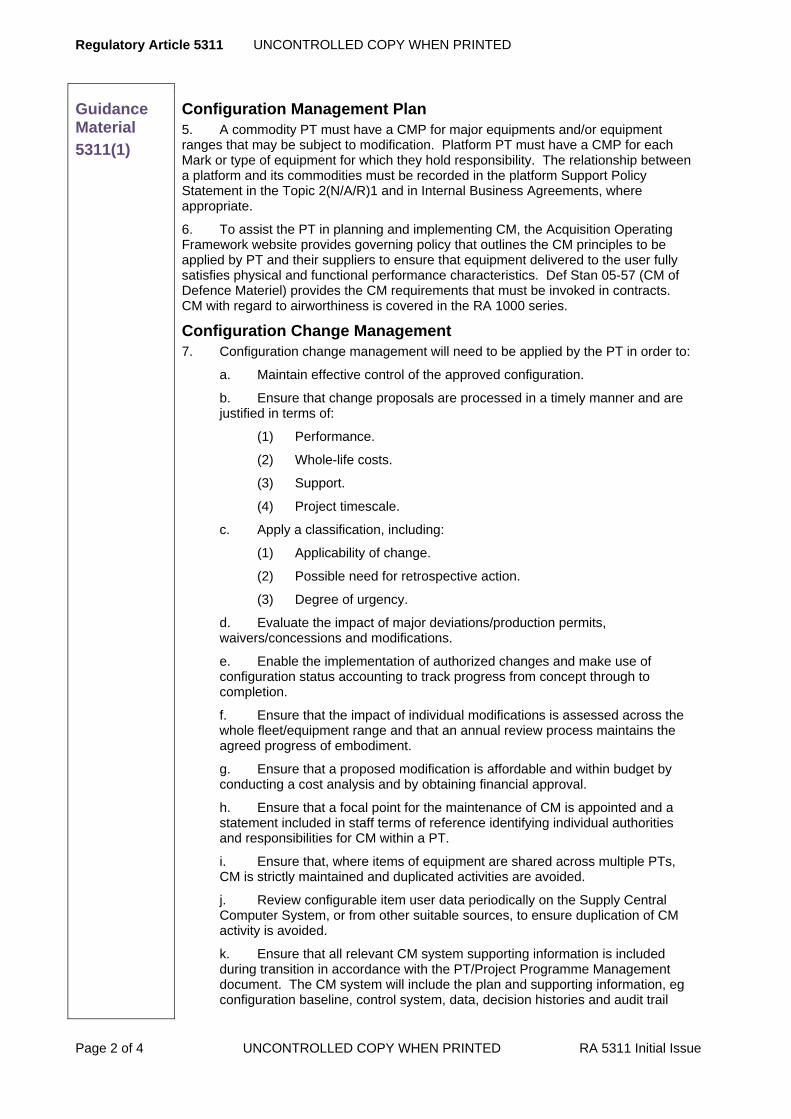
Regulatory Article 5311 UNCONTROLLED COPY WHEN PRINTED
Page 2 of 4 UNCONTROLLED COPY WHEN PRINTED RA 5311 Initial Issue
Guidance Material
5311(1)
Configuration Management Plan 5. A commodity PT must have a CMP for major equipments and/or equipment ranges that may be subject to modification. Platform PT must have a CMP for each Mark or type of equipment for which they hold responsibility. The relationship between a platform and its commodities must be recorded in the platform Support Policy Statement in the Topic 2(N/A/R)1 and in Internal Business Agreements, where appropriate.
6. To assist the PT in planning and implementing CM, the Acquisition Operating Framework website provides governing policy that outlines the CM principles to be applied by PT and their suppliers to ensure that equipment delivered to the user fully satisfies physical and functional performance characteristics. Def Stan 05-57 (CM of Defence Materiel) provides the CM requirements that must be invoked in contracts. CM with regard to airworthiness is covered in the RA 1000 series.
Configuration Change Management 7. Configuration change management will need to be applied by the PT in order to:
a. Maintain effective control of the approved configuration.
b. Ensure that change proposals are processed in a timely manner and are justified in terms of:
(1) Performance.
(2) Whole-life costs.
(3) Support.
(4) Project timescale.
c. Apply a classification, including:
(1) Applicability of change.
(2) Possible need for retrospective action.
(3) Degree of urgency.
d. Evaluate the impact of major deviations/production permits, waivers/concessions and modifications.
e. Enable the implementation of authorized changes and make use of configuration status accounting to track progress from concept through to completion.
f. Ensure that the impact of individual modifications is assessed across the whole fleet/equipment range and that an annual review process maintains the agreed progress of embodiment.
g. Ensure that a proposed modification is affordable and within budget by conducting a cost analysis and by obtaining financial approval.
h. Ensure that a focal point for the maintenance of CM is appointed and a statement included in staff terms of reference identifying individual authorities and responsibilities for CM within a PT.
i. Ensure that, where items of equipment are shared across multiple PTs, CM is strictly maintained and duplicated activities are avoided.
j. Review configurable item user data periodically on the Supply Central Computer System, or from other suitable sources, to ensure duplication of CM activity is avoided.
k. Ensure that all relevant CM system supporting information is included during transition in accordance with the PT/Project Programme Management document. The CM system will include the plan and supporting information, eg configuration baseline, control system, data, decision histories and audit trail

UNCONTROLLED COPY WHEN PRINTED Regulatory Article 5311
RA 5311 Initial Issue UNCONTROLLED COPY WHEN PRINTED Page 3 of 4
Guidance Material
5311(1)
records.
8. Initial Configuration Control (CC) is vested in the Designer, who provides the Configuration Status Record (CSR). This contains the indexes to master sets of drawings, amendments, modifications, ancillary equipment and Service-supply items. It must be kept up-to-date throughout the life of the equipment, on behalf of the PT, by either the Designer or an agent. The CSR provides a baseline for defining the as-fitted and modification state throughout the life of the equipment. Normally a CSR is produced for each item of equipment for which a Certificate of Design is required. Certification of the Design occurs when the PT Project Engineer and the Designer agree that the design meets the specification, subject to any exceptions or limitations.
9. Changes to design records must be carried out in accordance with RA 5000 series or as contracted. All modification procedures must conform to the guidelines and procedures described in this RA, the MAP, single-Service APs and any subordinate Business Procedures.
10. For Design Organization modifications, once a modification has been classified and appears in the CSR, information relating to its maintenance and repair must be included in the Topic 1 and Topic 6. The Publication Organization must ensure that the Design Organization amends the Topic 3.
11. For Service Modifications, the PT must ensure that a Service Amendment Leaflet (SAL), (format provided at MAP Chapter 8.2.2), is included in the affected Topics. The Topic 3 will only be amended if there is a cover modification. The PT must ensure that SM leaflets are published in the appropriate Topic 2 or AP 100N-03 series.
12. For all modifications the PT must ensure that Topic 5 maintenance schedules are amended. If the modification affects aircraft or equipment handling, refer to RA 5312.

Regulatory Article 5311 UNCONTROLLED COPY WHEN PRINTED
Page 4 of 4 UNCONTROLLED COPY WHEN PRINTED RA 5311 Initial Issue
Intentionally Blank for Print Pagination

UNCONTROLLED COPY WHEN PRINTED Regulatory Article 5312
RA 5312 Initial Issue UNCONTROLLED COPY WHEN PRINTED Page 1 of 6
RA 5312 – In-Service Design Changes
Rationale Following the introduction of an aircraft type into Service use it may be necessary to incorporate design changes to overcome deficiencies or to satisfy in-service requirements, eg improve safety, operational efficiency, capability, reliability, maintainability, and to ease production or overcome obsolescence. In-service design and procedural changes that affect aircraft must be conducted within a Safety Management System (SMS). In accordance with the SMS, it is imperative that the aircraft Safety Case, Release to Service (RTS) and supporting documentation are reviewed and updated.
Contents 5312(1): In-Service Design Changes
Regulation
5312(1)
In-Service Design Changes 5312(1) Prior to embodiment, all proposed in-service design changes
shall be assessed for safety and the Aircraft Document Set (ADS) updated accordingly. When emergency clearances are to be given, they shall be assessed for safety so far as is practicable and shall be reviewed when the emergency has passed.
Acceptable Means of Compliance
5312(1)
General 1. In-service design changes to aircraft and associated equipment should be conducted using Design Organization Modification (DM) and Service Modification (SM) procedures as described in RA 5313.
2. On initiating a design change PT should engage the Release to Service Authority (RTSA) and other specialist organizations at the earliest opportunity to allow sufficient time to assess the proposal and agree what evidence, if any, is required. This should enable the RTSA to incorporate the proposed change into the RTS and for the PT to update the Safety Case.
3. When an SM is incorporated, it should normally be superseded by a Design Organization (DO) cover modification to maintain configuration control of the drawing set; a cover modification should invariably to be sought when spares are affected.
4. The PT should ensure that, when selecting a DO for any design change, the DO has been approved under the MOD Design Approved Organization Scheme (DAOS). DAOS approval is a mandatory requirement defined in RA 5101.
Safety 5. The safety criteria for modifications to an aircraft, their associated equipment and software for peacetime and emergency flying should be in accordance with the RA 1200 series.
6. All DM and SM should be supported by their own Safety Cases, which should be assessed against, and integrated into, the whole aircraft Safety Case.
7. The PT should conduct a review of the whole aircraft Safety Case when progressing all design change proposals.
Responsibilities 8. The PT should take responsibility for:
a. Ensuring that a modification submission is comprehensive, accurate and

Regulatory Article 5312 UNCONTROLLED COPY WHEN PRINTED
Page 2 of 6 UNCONTROLLED COPY WHEN PRINTED RA 5312 Initial Issue
Acceptable Means of Compliance
5312(1)
worthwhile in terms of its acquisition cost and impact on support costs, is properly sponsored.
b. Identifying how the modification is likely to affect the maintenance of an aircraft or equipment and consider the requirement to amend any relevant maintenance schedules where appropriate.
c. Arranging for a Trial Installation (TI) and Proof Installation (PI), as required.
d. Notifying stakeholders, through a Routine Technical Instruction (RTI), of programme completion.
e. Conducting a post-project evaluation of the modification’s progression and embodiment, compiling a report on the objectives, costs and benefits achieved against original assumptions and, if applicable, assessing the value for money.
f. Assessing the lessons learnt for future reference and adjusting procedures accordingly.
g. Producing the embodiment plan, which needs to be agreed at a clearance conference.
h. Maintaining configuration control in accordance with RA 5311.
i. Ensuring that safety, airworthiness and engineering risks and through-life costs introduced by design changes are identified and reduced to As Low as Reasonably Practicable (ALARP).
j. Engaging the RTSA throughout the in-service design change process as appropriate to ensure that sufficient evidence is made available to enable the changes to be incorporated into the RTS.
k. Employing a rigorous system for managing modification programmes.
l. Ensuring that a review of the aircraft Safety Case is undertaken when incorporating design changes.
m. Obtaining appropriate specialist advice and endorsements, specifically where the Safety Case, RTS and aircraft/equipment clearances are affected.
n. Ensuring that the appropriate Management Information System is updated.
9. Additionally, Equipment PT should take responsibility for:
a. Ensuring that no equipment is installed in a UK military aircraft, or flown in a UK military aircraft without the prior approval of the appropriate platform PTL, whether for trial purposes or in-service use.
b. Ensuring that the Safety assessment for the equipment design change is promulgated to the appropriate platform PT for integration in the platform Safety Case.
10. Front Line Commands (FLC) should take responsibility for:
a. Supporting the need for modification.
b. Agreeing the modification programme.
c. Managing, as agreed with the PT, modification embodiment programmes carried out using FLC resources.
Proof Installations 11. If a PI is to be carried out at a Service establishment, the PT should take responsibility for:
a. Determining the type and mark of aircraft required and, if relevant, the modification state required.

UNCONTROLLED COPY WHEN PRINTED Regulatory Article 5312
RA 5312 Initial Issue UNCONTROLLED COPY WHEN PRINTED Page 3 of 6
Acceptable Means of Compliance
5312(1)
b. Deciding whether the PI will be embodied by a Contractors Working Party (CWP) or by Service personnel.
c. Arranging for provision of the Draft Modification Leaflet (DML).
d. Arranging for provision of the modification kit.
12. If a PI is to be carried out at a Service establishment, the FLC, in consultation with the PT, should take responsibility for ensuring that:
a. A suitable aircraft and embodiment opportunity are identified.
b. Suitable facilities are made available if the PI is to be embodied by CWP.
c. Arrangements are made for Service tradesman to do the work when the PI is not to be embodied by CWP.
d. The selected authority level K gives the required level of priority to embodiment of the PI, subject to any overriding operational commitments.
e. Additionally, where Service personnel are used, the authority level K must ensure that whilst normal responsibilities and regulations apply, the need for detailed assessment of the PI, and for drafting any report regarding any unsatisfactory features, may influence the seniority/experience of the personnel selected. No deviation from the DML is allowed without prior consent of the PT.
13. Full details of the parts, material and special tools required to embody a modification should be contained in the modification leaflet. In the leaflet, the terms “modification set” and “modification kit” may be used.
Guidance Material
5312(1)
General 14. Modification development and approval procedures for DM and SM are contained in RA 5313 and RA 5308.
15. Configuration Management (CM) systems, including the ADS and Integrated Logistic Support systems, must be updated in accordance with RA 5311 for all in-service design changes that affect aircraft or equipment configuration.
Safety 16. The aircraft Safety Case and RTS must be reviewed and updated for all proposed design changes, including those for trials purposes.
17. The aim is to meet the requirements of an in-service design change within the project’s safety targets. In some instances the design change may not be achievable within the safety targets and subsequent contingency operations must be covered. In all cases a safety analysis must be performed and the Safety Case updated in accordance with RA 1000 series.
18. PT may use the MOD Form 755 (SM2) – Safety and Support Questionnaire (SSQ) when assessing the effects of design change proposals against the Safety Case.
Modification Committees (MC) 19. Committees of technical and operational stakeholders normally conduct the management of the modification process.
20. An MC is normally chaired by the PT Project Engineer. Membership also includes PT staff covering project management, finance, engineering and supply, the Resident Project Officer, contractor’s representatives, plus Equipment Capability Customer and user staffs. Equipment PT and any associated flight simulator or synthetic trainer organizations may also represented when necessary.
21. PT may form separate MC for aircraft, engines and equipment. MC must approve all modifications appropriate to the aircraft, engine or equipment type and are

Regulatory Article 5312 UNCONTROLLED COPY WHEN PRINTED
Page 4 of 6 UNCONTROLLED COPY WHEN PRINTED RA 5312 Initial Issue
Guidance Material
5312(1)
required to award a classification that reflects their urgency and application.
22. Simple modifications may be approved and classified by the MC when first presented. Modifications that are more complex may be authorized for a Trial Installation and/or flight trials before being approved and classified.
23. Preliminary studies of in-service-proposed modifications are normally made by a Local Technical Committee (LTC) or equivalent. Technically approved proposals are then forwarded to the relevant committee for consideration.
24. Modifications to software are managed by Software Configuration Control Boards, either locally or at the Software Configuration Management Board, mirroring the LTC and MC functions. Software modification procedures are detailed in AP 100D-10.
Modification Proposals 25. Modification proposals stem from:
a. Continued development to meet the specification.
b. Faults in service.
c. New operational roles or the need to improve the effectiveness of existing roles.
d. The need to improve reliability, maintainability or cost-effectiveness.
e. Obsolescence of items or equipments.
26. FLC, operational and engineering staffs and the PT must assess proposals. If it is agreed that the proposal will be pursued, the PT will manage the modification’s development, using the most appropriate procedures. Control and scrutiny of the process are afforded by the use of committees to validate the proposal, its costs, progress and effect on other programmes.
27. Urgent Operational Requirements (UOR) can be applied in very specific circumstances when it is desired to procure new equipment and put it to operational use extremely quickly. It applies when the need arises for a rapid purchase of off-the-shelf or already developed equipment available from industry, or military stock from a friendly nation.
28. Operational Emergency Staff Requirements are processed on a priority basis in relation to normal Staff Requirements. The procedure is used when the circumstances require the urgent development and production of new equipment to meet an essential operational requirement.
29. Modifications are promulgated in tables in the Topic 2 of the platform or equipment, and/or must be recorded in the appropriate logistic information system, where required. For modifications that affect the handling of aircraft or equipment, refer to RA 5312. Alterations to modification leaflets are issued as amendments to the Topic 2.
Proof Installation 30. The DO may have to satisfy the PT that the modification can be embodied, and if necessary tested, without undue difficulty using Service effort, using the modification set and leaflet intended for issue. To confirm this, the PT may require the modification DO to conduct a PI of the modification. The PT must liaise with the FLC and authority level K of the designated Stn/Ship/Unit, stating any specific requirements, including the nature of any reports required.
31. A PI must remain embodied unless otherwise ordered by the PT. If the PI identifies any unsatisfactory features, the PT must instruct on any precautions or special measures that are to apply. Recording of the PI in aircraft and work documents must be as for an approved modification, except that entries must include the bracketed annotation (PI).

UNCONTROLLED COPY WHEN PRINTED Regulatory Article 5312
RA 5312 Initial Issue UNCONTROLLED COPY WHEN PRINTED Page 5 of 6
Guidance Material
5312(1)
32. The authority level K of the unit carrying out the PI must report the outcome of the installation to the PT using the format at Annex A.
Modification Embodiment 33. Embodiment will be dependent upon the availability of aircraft, modification kits and workforce. Aircraft will generally be modified during Depth maintenance; repairable components will generally be modified during repair or reconditioning. Modifications will not normally be embodied Forward; however, when warranted by flight safety or operational requirements, modifications may be ‘campaigned’ and this may require embodiment at both Forward and Depth. In this case the PT will liaise with FLC to manage an expeditious embodiment programme. Modifications must be incorporated in accordance with the priority accorded by the agreed embodiment plan.
34. The aircraft PT is responsible for arranging the modification of aircraft in storage. Depending on the storage category, aircraft will be modified either during their storage or immediately prior to issue.
35. The equipment PT is responsible for arranging the modification of equipment in store.
36. The Flight Simulator and Synthetic Training (FsAST) PT is responsible for arranging the embodiment of the modification into platform Synthetic Training Equipment.
Modification Kits 37. Once modification kits are available, expeditious modification embodiment is of prime importance to achieve maximum operational capability, reliability and maintainability from aircraft and equipments. Modification embodiment at all lines of maintenance must be given a high priority and must be actively managed.
38. A modification kit consists of one of the following:
a. A modification set and Service-supply items and/or Government Furnished Equipment added by the equipment supply depot before issue to the embodying unit.
b. An aggregation of Service-supply items required for a modification, but not requiring a modification set.
39. A modification set is supplied by the contractor and consists of:
a. All items of the contractor’s own manufacture.
b. Items that have been issued to the contractor on embodiment loan to complete the modification set.
c. The necessary AGS (Aerospace General Stores) parts.
d. All necessary bought-out items. (An item bought by one contractor from another).
e. Replacement seals, gaskets and similar consumable items needed for those assemblies that will be disturbed when embodying the modification.
Contractors Working Parties 40. The PT may approve the use of CWP, in accordance with MAP Chapter 4.8.2, to embody modifications either at a Stn/Ship/Unit or at the contractor’s works if the PT and FLC agree that the work required is outside Service capacity.
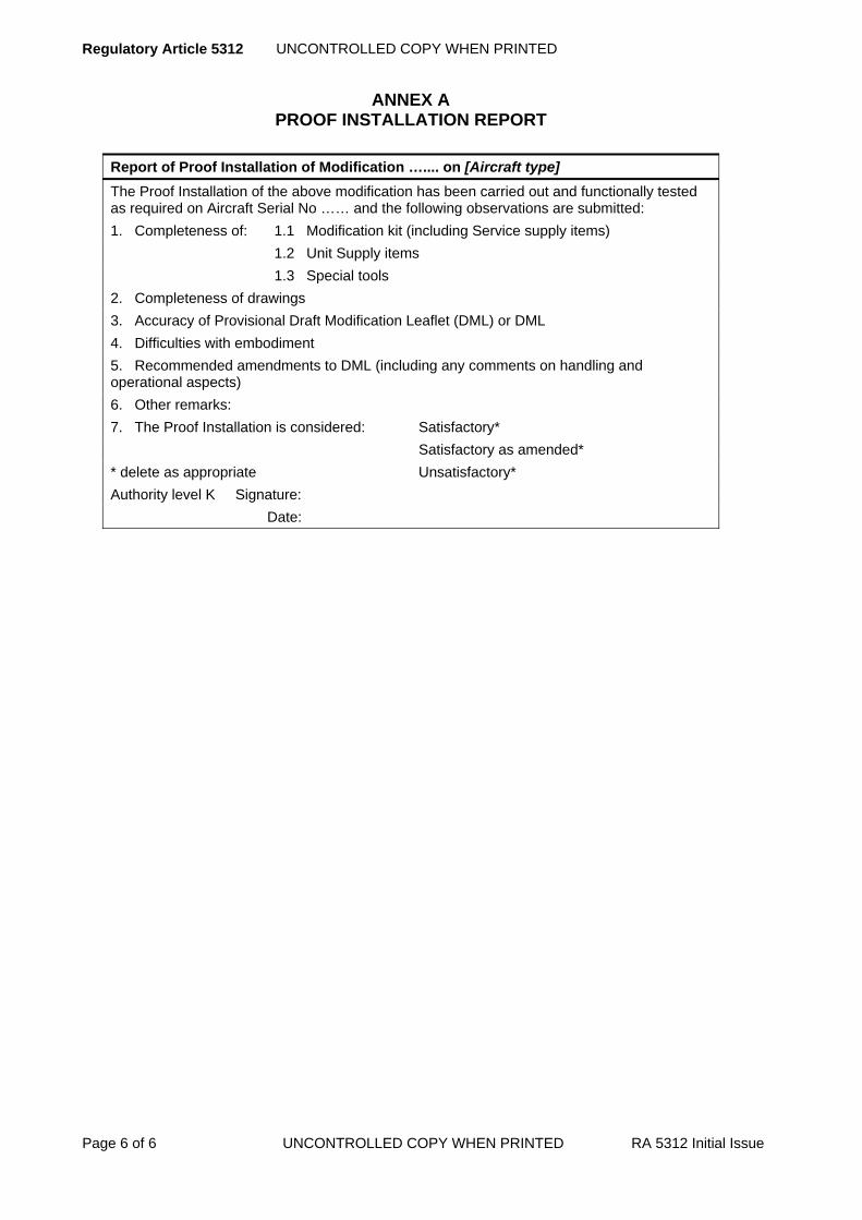
Regulatory Article 5312 UNCONTROLLED COPY WHEN PRINTED
Page 6 of 6 UNCONTROLLED COPY WHEN PRINTED RA 5312 Initial Issue
ANNEX A PROOF INSTALLATION REPORT
Report of Proof Installation of Modification ….... on [Aircraft type] The Proof Installation of the above modification has been carried out and functionally tested as required on Aircraft Serial No …… and the following observations are submitted: 1. Completeness of: 1.1 Modification kit (including Service supply items) 1.2 Unit Supply items 1.3 Special tools 2. Completeness of drawings 3. Accuracy of Provisional Draft Modification Leaflet (DML) or DML 4. Difficulties with embodiment 5. Recommended amendments to DML (including any comments on handling and operational aspects) 6. Other remarks: 7. The Proof Installation is considered: Satisfactory* Satisfactory as amended* * delete as appropriate Unsatisfactory* Authority level K Signature: Date:

UNCONTROLLED COPY WHEN PRINTED Regulatory Article 5313
RA 5313 Initial Issue UNCONTROLLED COPY WHEN PRINTED Page 1 of 10
RA 5313 - Design Modifications - Project Team
Rationale Changes to materiel are normally to be made by Design Organization Modification (DM) action where the aircraft or equipment Design Organization (DO) is contracted accordingly. The expeditious embodiment of modifications, once kits are available, is of prime importance to achieve maximum operational capability, reliability and maintainability from aircraft and equipments. The embodiment of modifications at all levels of maintenance is to be given a high priority and is to be actively managed.
Contents 5313(1): Design Modifications – Project Team
Regulation
5313(1)
Design Modifications – Project Team 5313(1) The Engineering Authority (EA) within the PT shall manage
the Design Organization Modification (DM) procedure
Acceptable Means of Compliance
5313(1)
1. This RA should be applicable to all materiel subject to DM, except that specifically excluded by separate contractual arrangements, eg weapons and some multi-national projects.
2. The PT should take responsibility for:
a. Editing the Draft Modification Leaflet (DML) or, when necessary, altering a published Topic 2 modification leaflet in accordance with the DML/Draft Information Leaflet (DIL) update process at Annex A.
b. Deciding whether an amendment proposal from the DO to a DML or a published Topic 2 modification leaflet is acceptable and, if so, how to implement it.
c. Briefing sheets, which should be used to keep the Modification Committees (MC) appraised of progress as the modification develops. Annexes B and C refer. The modification cost analysis sheet at Annex D should be used to inform financial decisions and declaring how the support costs for an operational modification are likely to change as a function of the modification.
3. Service Modifications (SM) can be useful to satisfy short term or limited applicability requirements, but where there is a need to make the modification a permanent change, to update publications and to ensure long term provisioning of spares, a DO cover modification should be sought.
4. A DO cover modification should incorporate details of the SM in the equipment Configuration Status Record:
a. Where the SM satisfies the design standards that the DO is contracted to maintain, the DO should adopt the SM design and produce a cover modification which ‘is satisfied by’ the SM.
b. Where the SM does not satisfy the contracted design standards, the DO should redesign the modification, possibly at a significant cost to the PT.
Guidance Material
5313(1)
5. A SM may be superseded by a DO cover modification to maintain configuration control of the drawing set. A DO cover modification is invariably to be sought when spares are affected.
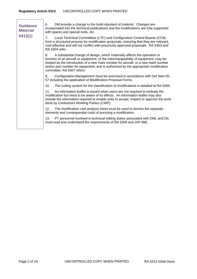
Regulatory Article 5313 UNCONTROLLED COPY WHEN PRINTED
Page 2 of 10 UNCONTROLLED COPY WHEN PRINTED RA 5313 Initial Issue
Guidance Material
5313(1)
6. DM provide a change to the build standard of materiel. Changes are incorporated into the technical publications and the modifications are fully supported with spares and special tools, etc.
7. Local Technical Committees (LTC) and Configuration Control Boards (CCB) form a structured process for modification proposals, ensuring that they are relevant, cost-effective and will not conflict with previously approved proposals. RA 5303 and RA 5304 refer.
8. A substantial change of design, which materially affects the operation or function of an aircraft or equipment, or the interchangeability of equipment, may be treated as the introduction of a new mark number for aircraft, or a new mark number and/or part number for equipment, and is authorized by the appropriate modification committee; RA 5307 refers.
9. Configuration Management must be exercised in accordance with Def Stan 05-57 including the application of Modification Proposal Forms.
10. The coding system for the classification of modifications is detailed at RA 5305.
11. An information leaflet is issued when users are not required to embody the modification but need to be aware of its effects. An information leaflet may also include the information required to enable units to accept, inspect or approve the work done by Contractors Working Parties (CWP).
12. The modification cost analysis sheet must be used to itemize the separate elements and consequential costs of pursuing a modification.
13. PT personnel involved in technical editing duties associated with DML and DIL must read and understand the requirements of RA 5306 and JSP 886.

UNCONTROLLED COPY WHEN PRINTED Regulatory Article 5313
RA 5313 Initial Issue UNCONTROLLED COPY WHEN PRINTED Page 3 of 10
ANNEX A DML/DIL PROCESS
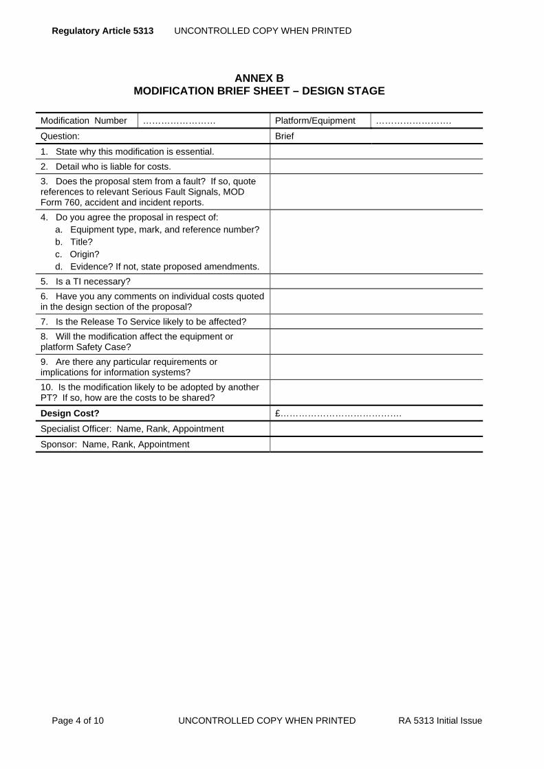
Regulatory Article 5313 UNCONTROLLED COPY WHEN PRINTED
Page 4 of 10 UNCONTROLLED COPY WHEN PRINTED RA 5313 Initial Issue
ANNEX B MODIFICATION BRIEF SHEET – DESIGN STAGE
Modification Number …………………… Platform/Equipment …………………….
Question: Brief
1. State why this modification is essential. 2. Detail who is liable for costs. 3. Does the proposal stem from a fault? If so, quote references to relevant Serious Fault Signals, MOD Form 760, accident and incident reports.
4. Do you agree the proposal in respect of: a. Equipment type, mark, and reference number? b. Title? c. Origin? d. Evidence? If not, state proposed amendments.
5. Is a TI necessary? 6. Have you any comments on individual costs quoted in the design section of the proposal?
7. Is the Release To Service likely to be affected? 8. Will the modification affect the equipment or platform Safety Case?
9. Are there any particular requirements or implications for information systems?
10. Is the modification likely to be adopted by another PT? If so, how are the costs to be shared?
Design Cost? £………………………………….
Specialist Officer: Name, Rank, Appointment
Sponsor: Name, Rank, Appointment

UNCONTROLLED COPY WHEN PRINTED Regulatory Article 5313
RA 5313 Initial Issue UNCONTROLLED COPY WHEN PRINTED Page 5 of 10
ANNEX C MODIFICATION BRIEF – CLASSIFICATION STAGE
Modification Number ……………………. Platform /Equipment …………………….
Question Brief
1. Have you assessed, in conjunction with the relevant EA and DO the spares implication of this modification by considering:
a. The cost of the modification sets and labour for spares held in Service and on order? b. Who will modify the spares? c. The cost of Service-supplied items for modification sets if no surplus assets are available? d. Can any of the modification set components be supplied from available Service assets? Has this been discussed at LTC level?
2. If major spares cannot be modified, have you assessed:
a. The costs of new post-modification spares to support the modified fleet? b. The cost of spares made redundant after the modification programme? c. Any financial liability resulting from cancellation of pre-modification spares orders?
3. Taking account of the embodiment backlog, priorities, opportunities, resources and the contractor's forecast delivery dates:
a. When will embodiment start? b. When will embodiment be complete? c. What is the planned programme?
4. What consequential or cover modifications will be required for:
a. Aircraft fit? b. Government Furnished Assets? c. Simulators? d. Training rigs? e. Test equipment?
5. If Service embodiment, and special tools are required, state:
a. Number of tools required. b. Allocation of tools.
6. Which of the following are required: DML, CWP-type DML, other type of DML or an information leaflet? (See Note)
7. What AP amendments will be required? 8. Will the Release To Service need amending? 9. Do you agree with the proposed modification set delivery dates and places?
10. What modification classification is required? 11. Will the modification be adopted by another PT? If

Regulatory Article 5313 UNCONTROLLED COPY WHEN PRINTED
Page 6 of 10 UNCONTROLLED COPY WHEN PRINTED RA 5313 Initial Issue
Modification Number ……………………. Platform /Equipment …………………….
Question Brief so, how are costs to be shared? 12. Will this modification affect any other embodiment programme? If so, what are the effects and consequent programme changes required?
Total Sponsorship Cost:
Specialist Officer: Name, Rank, Appointment
Sponsor: Name, Rank, Appointment

UNCONTROLLED COPY WHEN PRINTED Regulatory Article 5313
RA 5313 Initial Issue UNCONTROLLED COPY WHEN PRINTED Page 7 of 10
ANNEX D MODIFICATION COST ANALYSIS SHEET
Firm ………………… Equipment ………………….. Modification No……………..
1. This submission represents: Part of a package of modifications (complete Blocks 1 & 2) Part of an independent modification (complete Blocks 1 & 2) A change to previous sponsorship (complete Blocks 1 & 2) A complete independent modification (complete Block 2)
BLOCK 1
2. The package/modification, including any consequential modifications at Annex C, paragraph 4 of the brief sheet:
Has already been sponsored (complete Part A) Needs to be sponsored now: For the first time (complete Part B) Because of a change (complete Parts A & B) 3. Part A – Already Sponsored
Modification No/ Stage Estimated Cost Sponsored by
…………..………… £ .….………………… Appt …………..……………………… …………..………… £ .….………………… Modification Sheet Ref …..………… …………..………… £ .….………………… Date …………..…………
Total £ .….…………………
Submit for financial approval (note 2)
4. Part B – To be Sponsored Now
Modification No/ Stage Estimated Cost Reasons for any change
…………..………… £ .….………………… .….……………….….………… …………..………… £ .….………………… .….……………….….………… …………..………… £ .….………………… .….……………….….………… …………..………… £ .….………………… .….……………….….…………
Total £ .….…………………
Submit for financial approval (note 2)
BLOCK 2
5. Complete as appropriate Complete Modification Design Stage Production Stage Long Lead Items Other ………………………………………………………………
a. Design Costs

Regulatory Article 5313 UNCONTROLLED COPY WHEN PRINTED
Page 8 of 10 UNCONTROLLED COPY WHEN PRINTED RA 5313 Initial Issue
(1) Preparation £ ……………….. (2) Trial installation £ ……………….. (3) Flight trials £ ……………….. (4) Ground/Bench tests £ ……………….. (5) Design incorporation (total) £ ……………….. including DML £ ……………….. Publication amendments £ ……………….. (6) Proof Installation £ ………………..
Total Design £ ………………..
b. Production Costs
(1) Changes in production @ £ ………… £ ……………….. (2) Modification sets for in-service fleet @ £ ………… £ ……………….. (3) Return to Works @ £ ………… £ ……………….. (4) On repair or recondition @ £ ………… £ ……………….. (5) Retrofit before delivery @ £ ………… £ ……………….. (6) Scrap: In production £ ……………….. Retro before delivery £ ……………….. (7) Contractor’s production and embodiment tooling £ ………………..
Total Production £ ………………..
c. Effect on Spares (3)
(1) Modification Sets for spares @ £ ………… £ ……………….. (2) Service supplied items and
Government Furnished Equipment to convert all modification sets to kits
@ £ ………… £ ………………..
(3) Redundant spares and tooling £ ……………….. (4) Cancelled spares orders £ ………………..
Total Spares £ ……………….. d. Embodiment Costs
(1) Service tooling @ £ ………… £ ……………….. (2) CWP Manpower @ £ ………… £ ……………….. (3) Test equipment @ £ ………… £ ………………..
Total Embodiment £ ………………..
(4) Service man-hours (4) …………@………… = £……………….. (Service man-hours are to be declared, but excluded from
sum sponsored)
e. Modification of FsAST (Applicable/Non-applicable)
(1) Modification Sets (inc spares) @ £ ………… £ ……………….. (2) Service supplied items and
Government Furnished Equipment @ £ …………
£ ………………..
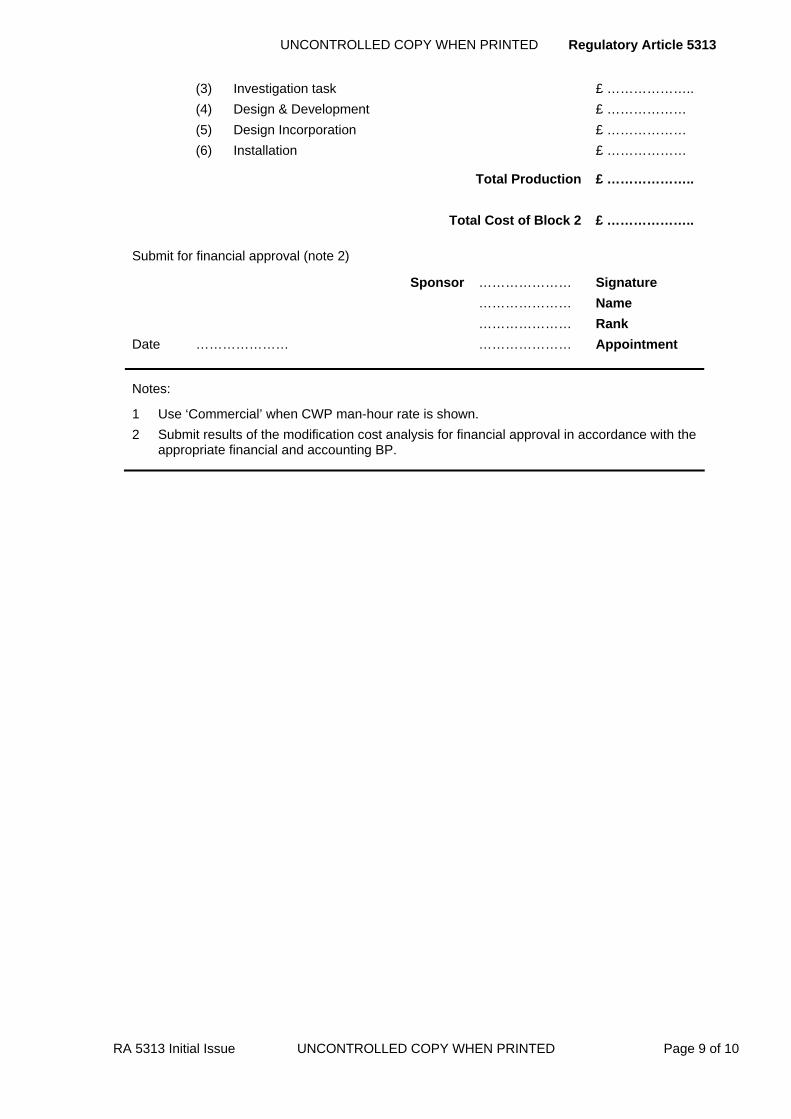
UNCONTROLLED COPY WHEN PRINTED Regulatory Article 5313
RA 5313 Initial Issue UNCONTROLLED COPY WHEN PRINTED Page 9 of 10
(3) Investigation task £ ……………….. (4) Design & Development £ ……………… (5) Design Incorporation £ ……………… (6) Installation £ ………………
Total Production £ ………………..
Total Cost of Block 2 £ ………………..
Submit for financial approval (note 2)
Sponsor ………………… Signature
………………… Name
………………… Rank
Date ………………… ………………… Appointment
Notes:
1 Use ‘Commercial’ when CWP man-hour rate is shown. 2 Submit results of the modification cost analysis for financial approval in accordance with the
appropriate financial and accounting BP.

Regulatory Article 5313 UNCONTROLLED COPY WHEN PRINTED
Page 10 of 10 UNCONTROLLED COPY WHEN PRINTED RA 5313 Initial Issue
Intentionally Blank for Print Pagination

UNCONTROLLED COPY WHEN PRINTED Regulatory Article 5320
RA 5320 Issue 2 UNCONTROLLED COPY WHEN PRINTED Page 1 of 2
RA 5320 - Aircraft Maintenance Programme – Design Guidelines
Rationale Levels of airworthiness can be maintained by the implementation of recognised protocols, ►such as Reliability Centred Maintenance (RCM)◄, in an aircraft maintenance programme, which will also have the potential to reduce aircraft maintenance costs.
Contents 5320(1): Aircraft Maintenance Programme – Design Guidelines
Regulation
5320(1)
Aircraft Maintenance Programme – Design Guidelines 5320(1) Each aircraft Type Airworthiness Authority (TAA) shall
ensure the protocols of an aircraft maintenance programme are implemented throughout the ►life of the project◄.
Acceptable Means of Compliance
5320(1)
Aircraft Maintenance Programme – Design Guidelines 1. Either of the following aircraft maintenance protocols should be used:
a. JAP(D)100C-22 (Guide to Developing and Sustaining Preventative Maintenance Programmes).
b. ATA MSG-3.
2. The aircraft maintenance programme should contain details, including frequency, of all maintenance to be carried out and any specific tasks linked to the type of operations.
3. The aircraft maintenance programme should be subject to periodic reviews, which need to take account of operating experience and any changes to the maintenance regime ►proposed by the Design Organization (DO) and◄ promulgated by the TAA and amended accordingly when necessary.
4. ►Any preventive maintenance schedule should be derived and reviewed in conjunction with the DO◄.
Guidance Material
5320(1)
Aircraft Maintenance Programme – Design Guidelines
5. Other protocols may satisfy some or all of the requirements identified in the standards above. Consultation with the MAA will be required to establish the degree of parity.
6. The procedures for preventive maintenance are identified within RA4203. The procedures for production and maintenance of maintenance schedules are identified within RA4351.

Regulatory Article 5320 UNCONTROLLED COPY WHEN PRINTED
Page 2 of 2 UNCONTROLLED COPY WHEN PRINTED RA 5320 Issue 2
Intentionally Blank for Print Pagination

UNCONTROLLED COPY WHEN PRINTED Regulatory Article 5401
RA 5401 Issue 2 UNCONTROLLED COPY WHEN PRINTED Page 1 of 8
►This RA has been substantially re-written; for clarity no change marks are presented - please read RA in entirety◄
RA 5401 – Provision of Service Technical Publications
Rationale With the procurement and provision of Service Technical Publications there is a need to assure the accuracy of the data and the timeliness of any subsequent amendments to the publications.
Contents 5401(1): Provision of Service Technical Publications 5401(2): Validation of Service Technical Publications
5401(3): Verification of Service Technical Publications
5401(4): Amendments to Service Technical Publications
Regulation
5401(1)
Provision of Service Technical Publications 5401(1) The Contractor shall provide quality assured Technical
Information and Data (TID).
Acceptable Means of Compliance
5401(1)
Provision of Service Technical Publications
1. TID should be provided for the appropriate range of publications taken from the contracted Technical Publication Plan (TPP) to the requirements of the contracted publication specifications.
2. The layout and technical content of legacy material should be as detailed in the specifications listed in Annex A.
3. The layout and technical content of Information Sets for new material should be as defined in specification ASD/AIA S1000D.
4. Unless the contract or publications specification stipulates otherwise, the first issue of any Service publication should relate to the design standard of the first equipment delivered to the Services for operational use.
5. Where publications are already available for equipment the Contractor should agree with the Publications Organization (PO) any changes or additional support information necessary to make such publications acceptable.
6. The Contractor should provide quality assurance of the TID that he supplies. If required he should produce a publications quality plan covering his quality arrangements for publications if such arrangements are not already covered in his existing contract quality plan.
7. Where an item, which forms part of a larger assembly, requires in-situ maintenance, the supplier of the item should provide TID for incorporation in the maintenance publication for the assembly. The Project Team Leader (PTL) should provide maintenance information on Government Furnished Assets (GFA).
8. The Contractor should ensure that all publications material required for items developed or supplied by his sub-contractors complies with the general and specific requirements and specifications for Service technical publications.
9. Publications should be complete and distributed before the materiel reaches the Service(s). Delivery of publications material by a Contractor may be made in instalments agreed with the PTL.

Regulatory Article 5401 UNCONTROLLED COPY WHEN PRINTED
Page 2 of 8 UNCONTROLLED COPY WHEN PRINTED RA 5401 Issue 2
Guidance Material
5401(1)
Provision of Service Technical Publications 10. The term TID is used throughout to denote Logistic Supportability Analysis (LSA) data; Data Modules (DMs); draft text or illustrations; reproducible Master Material (MM); Interactive Electronic Technical Publications (IETPs) and any output derived from such regardless of the media.
11. The provision of TID for new materiel is normally developed as an element within the project Integrated Logistic Support (ILS) plan.
12. Where the Contractor is in doubt whether TID prepared by a sub-contractor meets the requirements he is to consult the appropriate PO; this is particularly important when a sub-contractor offers existing publications.
13. The Contractor is responsible for obtaining and supplying the required copies of any AvP or JSP specifications and/or copies of current MOD technical publications to his sub-contractors. He is to ensure that these documents are properly maintained during the period of the sub-contract and withdraw them on completion of the sub-contract.
14. The DO or sub-contractor is responsible for the safe custody of all publications master material that he has prepared until that responsibility is transferred or terminated.
15. The Contractor must ensure that the copyright of all TID supplied in satisfaction of a contract is vested in him or that he has written permission from any other copyright holder to make use of such material. The Crown requires free licence to reproduce the TID in whole or in part for any UK Government purpose in accordance with DefCon 90.
16. The most commonly used referencing systems for Service technical publications covering Aircraft Publications are shown below. Where special circumstances require the use of other specifications (e.g. for microfiche) the appropriate requirements are to be stated in the contract.
17. Topic Numbers1 and Categories for Aircraft Publications are as follows:
a. Topic 1 Aircraft Maintenance Manual or General and Technical Information
b. Topic 2 General Orders and Special Instructions
c. Topic 2(N/A/R)1 General Orders and Special Instructions
d. Topic 3A Illustrated Parts Catalogue (IPC)
e. Topic 3B Appendix A – Schedule of Equipment
f. Topic 5 Basic (Periodic) Maintenance Schedules
g. Topic 6 Repair and Reconditioning Instructions
h. Topic 6A Aircraft repair manual
i. Topic 6B Aircraft reconditioning manual
j. Topic 6C Aircraft Battle Damage Repair Manual (ABDRM)
k. Topic 7 Preservation, packaging, transport and storage manual
l. Topic 9 Weight and balance data manual (Transport aircraft only)
m. Topic 10 Aircraft Maintenance Diagrams Manual (AMDM)
n. Topic 11A Air Transport Operations Manual (ATOM)
o. Topic 12A Ground Handling notes
p. Topic 12B Cross-servicing guide
q. Topic 12C Engine Ground running reference cards
1 These are legacy topic headings. Reference to the current definitions of Information Sets is given in paragraph 3.

UNCONTROLLED COPY WHEN PRINTED Regulatory Article 5401
RA 5401 Issue 2 UNCONTROLLED COPY WHEN PRINTED Page 3 of 8
Guidance Material
5401(1)
r. Topic 14 Flight Reference Cards
s. Topic 15 Aircrew Manual
t. Topic 15S Statement of Operating Intent
u. Topic 16 Operating Data Manual (ODM)
Regulation
5401(2)
Validation of Service Technical Publications 5401(2) The Contractor/Design Organization (DO) or, in certain
circumstances, the PTL or members of his team with appropriate airworthiness delegation shall validate and certify that all the information contained within a TID suite is accurate, safe in application and suitable for its intended purpose as defined in the contract.
Acceptable Means of Compliance
5401(2)
Validation of Service Technical Publications 18. For new projects, and amendments that justify it, the DO should submit to the PTL, or his delegated PO as appropriate, his proposed validation programme, nominating the proposed method(s) of validation for procedural material. Acceptance of these proposals should be confirmed by written agreement between the DO and the PTL.
19. Practical validation trials should be conducted under conditions that provide reasonable assurance that the procedure can be accomplished under normal Service conditions. These trials should follow the sequence of operations as written, using tools and test equipment, operator skills and manning levels representative of those specified for use by the Service. The trials should confirm the DO recommendations for standard and special tools and manning levels necessary to ensure compliance with the stated Service maintenance policy.
20. At the conclusion of validation, all work delivered to the PO for acceptance should be accompanied by certification of validation by the DO. The form of the certification and the nominated signatory should be subject to approval by the PO.
Guidance Material
5401(2)
Validation of Service Technical Publications 21. To amplify the requirements of this RA, more detailed specific requirements for first verification may be called up in the contract that covers the preparation of the TID.
22. The requirements specified in this RA are applicable to all technical publications and to both the initial issue and subsequent amendments of publications.
23. There are two basic types of information contained in TID; descriptive and procedural. Validation is required of both.
24. Descriptive material is validated by means of a comparative check against design source material to ensure its accuracy.
25. Procedural material may be validated in three ways:
a. A practical trial of the procedure.
b. A simulated practical trial whereby the text is taken to the materiel concerned and the procedure is ‘talked through’.
c. A ‘table-top’ comparison with a similar procedure that has been subject to practical trial.
26. Engineering judgement will be required by the DO in deciding on the method or methods of validation which are necessary. The decision will be influenced by the type of information, the consequences of error, the complexity of the procedure, the availability of facilities, cost-benefit, etc. In exercising engineering judgement for
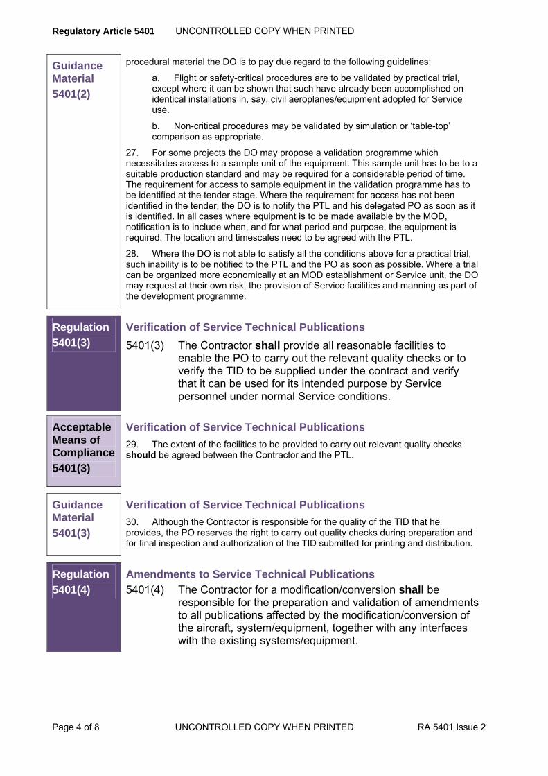
Regulatory Article 5401 UNCONTROLLED COPY WHEN PRINTED
Page 4 of 8 UNCONTROLLED COPY WHEN PRINTED RA 5401 Issue 2
Guidance Material
5401(2)
procedural material the DO is to pay due regard to the following guidelines:
a. Flight or safety-critical procedures are to be validated by practical trial, except where it can be shown that such have already been accomplished on identical installations in, say, civil aeroplanes/equipment adopted for Service use.
b. Non-critical procedures may be validated by simulation or ‘table-top’ comparison as appropriate.
27. For some projects the DO may propose a validation programme which necessitates access to a sample unit of the equipment. This sample unit has to be to a suitable production standard and may be required for a considerable period of time. The requirement for access to sample equipment in the validation programme has to be identified at the tender stage. Where the requirement for access has not been identified in the tender, the DO is to notify the PTL and his delegated PO as soon as it is identified. In all cases where equipment is to be made available by the MOD, notification is to include when, and for what period and purpose, the equipment is required. The location and timescales need to be agreed with the PTL.
28. Where the DO is not able to satisfy all the conditions above for a practical trial, such inability is to be notified to the PTL and the PO as soon as possible. Where a trial can be organized more economically at an MOD establishment or Service unit, the DO may request at their own risk, the provision of Service facilities and manning as part of the development programme.
Regulation
5401(3)
Verification of Service Technical Publications
5401(3) The Contractor shall provide all reasonable facilities to enable the PO to carry out the relevant quality checks or to verify the TID to be supplied under the contract and verify that it can be used for its intended purpose by Service personnel under normal Service conditions.
Acceptable Means of Compliance
5401(3)
Verification of Service Technical Publications
29. The extent of the facilities to be provided to carry out relevant quality checks should be agreed between the Contractor and the PTL.
Guidance Material
5401(3)
Verification of Service Technical Publications
30. Although the Contractor is responsible for the quality of the TID that he provides, the PO reserves the right to carry out quality checks during preparation and for final inspection and authorization of the TID submitted for printing and distribution.
Regulation
5401(4)
Amendments to Service Technical Publications
5401(4) The Contractor for a modification/conversion shall be responsible for the preparation and validation of amendments to all publications affected by the modification/conversion of the aircraft, system/equipment, together with any interfaces with the existing systems/equipment.
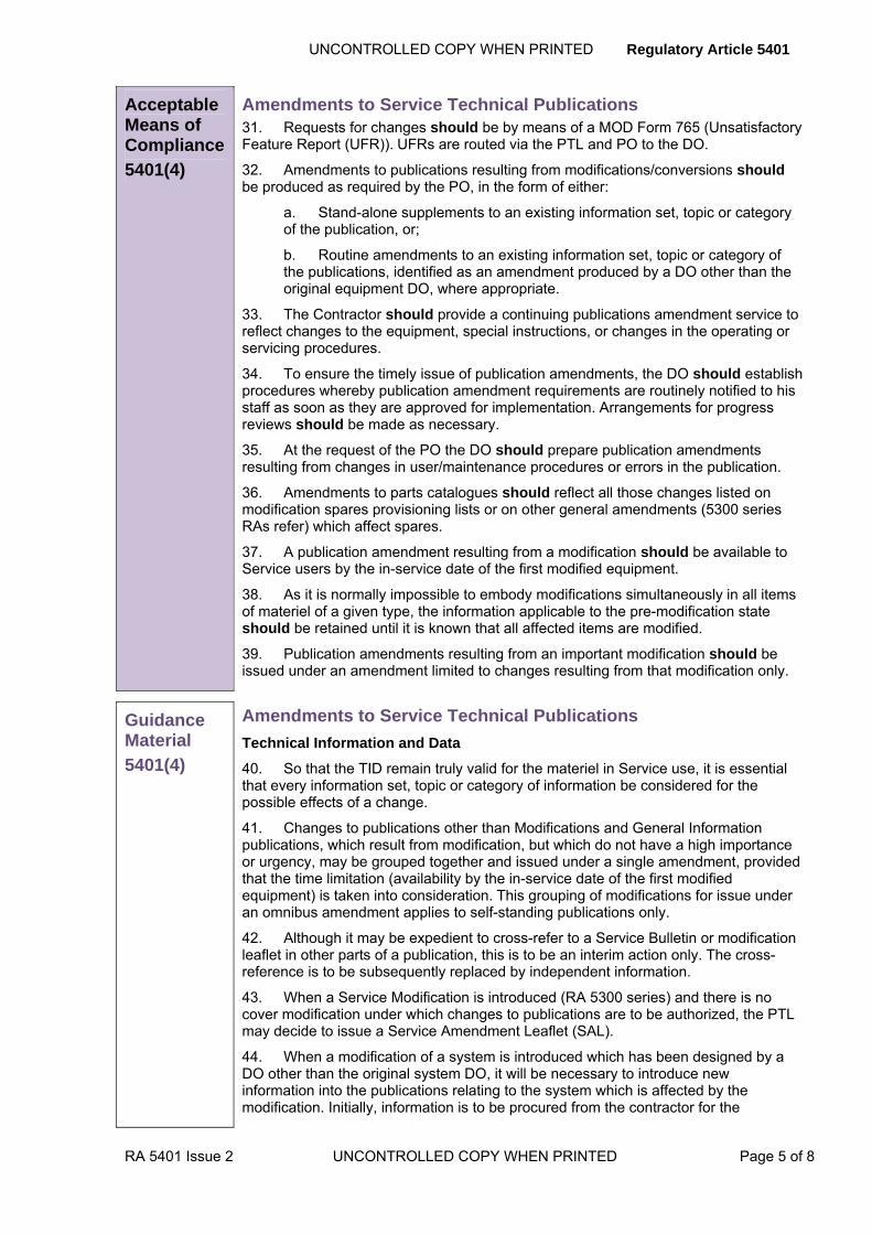
UNCONTROLLED COPY WHEN PRINTED Regulatory Article 5401
RA 5401 Issue 2 UNCONTROLLED COPY WHEN PRINTED Page 5 of 8
Acceptable Means of Compliance
5401(4)
Amendments to Service Technical Publications 31. Requests for changes should be by means of a MOD Form 765 (Unsatisfactory Feature Report (UFR)). UFRs are routed via the PTL and PO to the DO.
32. Amendments to publications resulting from modifications/conversions should be produced as required by the PO, in the form of either:
a. Stand-alone supplements to an existing information set, topic or category of the publication, or;
b. Routine amendments to an existing information set, topic or category of the publications, identified as an amendment produced by a DO other than the original equipment DO, where appropriate.
33. The Contractor should provide a continuing publications amendment service to reflect changes to the equipment, special instructions, or changes in the operating or servicing procedures.
34. To ensure the timely issue of publication amendments, the DO should establish procedures whereby publication amendment requirements are routinely notified to his staff as soon as they are approved for implementation. Arrangements for progress reviews should be made as necessary.
35. At the request of the PO the DO should prepare publication amendments resulting from changes in user/maintenance procedures or errors in the publication.
36. Amendments to parts catalogues should reflect all those changes listed on modification spares provisioning lists or on other general amendments (5300 series RAs refer) which affect spares.
37. A publication amendment resulting from a modification should be available to Service users by the in-service date of the first modified equipment.
38. As it is normally impossible to embody modifications simultaneously in all items of materiel of a given type, the information applicable to the pre-modification state should be retained until it is known that all affected items are modified.
39. Publication amendments resulting from an important modification should be issued under an amendment limited to changes resulting from that modification only.
Guidance Material
5401(4)
Amendments to Service Technical Publications
Technical Information and Data
40. So that the TID remain truly valid for the materiel in Service use, it is essential that every information set, topic or category of information be considered for the possible effects of a change.
41. Changes to publications other than Modifications and General Information publications, which result from modification, but which do not have a high importance or urgency, may be grouped together and issued under a single amendment, provided that the time limitation (availability by the in-service date of the first modified equipment) is taken into consideration. This grouping of modifications for issue under an omnibus amendment applies to self-standing publications only.
42. Although it may be expedient to cross-refer to a Service Bulletin or modification leaflet in other parts of a publication, this is to be an interim action only. The cross-reference is to be subsequently replaced by independent information.
43. When a Service Modification is introduced (RA 5300 series) and there is no cover modification under which changes to publications are to be authorized, the PTL may decide to issue a Service Amendment Leaflet (SAL).
44. When a modification of a system is introduced which has been designed by a DO other than the original system DO, it will be necessary to introduce new information into the publications relating to the system which is affected by the modification. Initially, information is to be procured from the contractor for the

Regulatory Article 5401 UNCONTROLLED COPY WHEN PRINTED
Page 6 of 8 UNCONTROLLED COPY WHEN PRINTED RA 5401 Issue 2
Guidance Material
5401(4)
modification as a deliverable from the modification contract and provided to the publication users in one of the following two forms:
a. It may be issued in the form of a ‘stand alone’ supplement to the existing particular publication. The supplement is to be issued under cover of a letter from the TAA authorizing its use pending the issue of a formal DO amendment. A ‘Notice (or Notices) to Readers’ is to be inserted in the parent publication by amendment action, adjacent to and facing the affected material to draw the attention of readers to the existence of the ‘Supplement’ and define the circumstances in which the supplement takes precedence over the affected material. The notice is to be printed on yellow paper in the quality range 80-95g/m2.
b. Information provided by the Contractor is to be compiled for insertion in the normal amendment format. No extant information may be removed from the publication. The resulting amendment is to be given an amendment number in the normal amendment sequence, published and inserted into the publication by routine amendment action as required by para 46a. above. The inserted material is to be identified as a ‘Modification DO Amendment’, and is to have the following distinctive features:
(1) Modification DO Amendments are to be printed on yellow paper in the quality range 80-95g/m2.
(2) A ‘Notice (or Notices) to Readers’ is to be provided in the form of an additional page(s) inserted into the preliminary material of the publication. The ‘Notice(s)’ is to draw the reader’s attention to the fact that the validation of the supplementary information introduced by the amendment, has been carried out by the modification DO. The notice is to define the circumstances in which the supplement takes precedence over the affected material. It is also to provide details of the way in which the pages containing supplementary information are identified.
(3) The pages which are introduced by a Modification DO Amendment are to be identified thus: A ‘caption’ is to be included on each page, located at the top of the page and on the opposite side to the publication identification reference number. The caption is to consist of the modification DO name on the same line as the publication reference number, followed by the word ‘Supplement’ on the next line. When a modification number has been allocated, the words ‘Post Mod XXX’ are to appear on the third line, indicating the number of the modification to which the supplementary information relates e.g.
Security Classification
ACME Electronics Plc AP 999A-0101-1
Supplement
Post Mod 990099
(4) The supplementary information is to be inserted as necessary. The material, where convenient, is to be inserted into the original publication in such a manner as to be easily related to the original text or illustrations. Supplementary contents lists are to face original contents lists. Where single pages are introduced these are to be inserted to face the page bearing the information which is superseded when the modification is embodied. When a complete prime unit is introduced, the supplementary unit is to be inserted to follow the existing unit and a supplementary contents page is to be inserted to face the contents page of the affected existing prime unit.
(5) The pages introduced by a Modification DO Amendment are to bear the chapter and page number of the page which they are inserted to follow, with numeric suffixes as necessary.

UNCONTROLLED COPY WHEN PRINTED Regulatory Article 5401
RA 5401 Issue 2 UNCONTROLLED COPY WHEN PRINTED Page 7 of 8
Guidance Material
5401(4)
Examples:
When supplementary pages are inserted in Chapter 4 to follow page 14 they are to be identified as follows:
Chap 4 Chap 4 Chap 4
Page 14(1) Page 14(2) Page 14(3) et seq
When supplementary pages are inserted in Chapter 6 to follow page 12B they are to be identified as follows:
Chap 6 Chap 6 Chap 6
Page 12B(1)Page 12B(2) Page 12B(3) et seq
(6) A list of effective pages (LEP) is to be provided with each Modification DO Amendment bearing the ‘caption’ as specified in (3) above and be printed on yellow paper. The LEP is to detail all the pages of the publication which exist after the amendment has been incorporated. Where an LEP already exists a new supplementary LEP is to be introduced to show the additional pages introduced by the amendment
45. The PTL for the aircraft, system or equipment is to initiate arrangements for design incorporation of the modification. When this has been done, probably by the issue of a ‘cover modification’, a DO-originated and validated amendment is to be procured as outlined above in order to formally incorporate the new information into the publication.
Special Instructions (Technical)
46. A Special Instructions (Technical) SI(T) may contain information which supersedes that contained in the TID and may call for a publication amendment.
47. When a SI(T) is to be followed by modification of the materiel; the publications will normally be amended as part of the modification process.
48. SI(T) normally contain a note indicating whether or not publications are to be amended.
49. Spares affected by modifications introduced other than by the original system DO, are not to be entered into the catalogue without a covering modification except that the PA may request a cross-reference to the SI(T). In cases where the PTL requires details of spares introduced by SM to be entered in the catalogue, a SAL may be issued.
Advance Information Leaflets (AIL)
50. When more urgent amendment action is desirable, the DO (after reviewing the instruction) or the PTL may consider it necessary for an Advance Information Leaflet (AIL) to be prepared. Before doing this, the DO is to consult the appropriate PO. An AIL is a temporary publication amendment which is to be reviewed monthly to ensure its inclusion in a normal publication amendment at the earliest opportunity.
51. Amendment lists are to be prepared and issued by the DO on a regular basis, at least half yearly, if amendment is required. The size of any amendment is to be restricted to a total of 200 pages (excluding the indexes) except where a major single modification generates more than this number of pages for amendment action.
52. Amendments to indexes may be made by the issue of a supplementary part number index, but this is to be followed by the complete revision of the index within 12 months of the issue of the supplementary list.
53. Where Service and/or NATO stock numbers are required to be included, in a parts catalogue, the DO is responsible for obtaining details of the stock numbers and updating the appropriate areas of the publications.

Regulatory Article 5401 UNCONTROLLED COPY WHEN PRINTED
Page 8 of 8 UNCONTROLLED COPY WHEN PRINTED RA 5401 Issue 2
ANNEX A
GENERAL SPECIFICATIONS
A.1 Joint Service specifications:
Specification Title
JSP(D) 543 Specifications for air technical publications
A.2 Specifications for aircraft and aircraft equipment publications for Royal Navy, Army and Royal Air Force:
Specification Title
JSP(D) 543 Specifications for air technical publications
A.3 Specification or publications for Royal Navy ship launched weapon systems:
Specification Title
Def Stan 02-40 Requirements for the Preparation of Technical Publications
Part 1; Systems
and Equipment
April 2000
A.4 Specification for Army Department publications:
Specification Title
JSP(D) 543 Specifications for air technical publications

UNCONTROLLED COPY WHEN PRINTED Regulatory Article 5402
RA 5402 Issue 3 UNCONTROLLED COPY WHEN PRINTED Page 1 of 2
RA 5402 - Validation and Verification of Service Technical Publications
Rationale ►Withdrawn – Incorporated into RA 5401(2) and RA 5401(3))◄
Contents 5402(1): ►Withdrawn – Incorporated into RA 5401(2)◄
5402(2): ►Withdrawn – Incorporated into RA 5401(3)◄
Regulation
5402(1)
Validation of Service Technical Publications 5402(1) ►Withdrawn – Incorporated into RA 5401(2)◄
Acceptable Means of Compliance
5402(1)
Validation of Service Technical Publications 1. ►Withdrawn – Incorporated into RA 5401(2)◄
Guidance Material
5402(1)
Validation of Service Technical Publications 2. ►Withdrawn – Incorporated into RA 5401(2)◄
Regulation
5402(2)
Verification of Service Technical Publications 5402(2) ►Withdrawn – Incorporated into RA 5401(3)◄
Acceptable Means of Compliance
5402(2)
Verification of Service Technical Publications 3. ►Withdrawn – Incorporated into RA 5401(3)◄
Guidance Material
5402(2)
Verification of Service Technical Publications 4. ►Withdrawn – Incorporated into RA 5401(3)◄

Regulatory Article 5402 UNCONTROLLED COPY WHEN PRINTED
Page 2 of 2 UNCONTROLLED COPY WHEN PRINTED RA 5402 Issue 3
Intentionally Blank for Print Pagination

UNCONTROLLED COPY WHEN PRINTED Regulatory Article 5403
RA 5403 Issue 2 UNCONTROLLED COPY WHEN PRINTED Page 1 of 2
RA 5403 - Amendments to Service Technical Publications
Rationale Withdrawn – Incorporated into RA 5401(4))
Contents 5403(1): Withdrawn – Incorporated into RA 5401(4)
Regulation
5403(1)
Amendments to Service Technical Publications 5403(1) Withdrawn – Incorporated into RA 5401(4)
Acceptable Means of Compliance
5403(1)
Amendments to Service Technical Publications 1. Withdrawn – Incorporated into RA 5401(4)
Guidance Material
5403(1)
Amendments to Service Technical Publications 2. Withdrawn – Incorporated into RA 5401(4)

Regulatory Article 5403 UNCONTROLLED COPY WHEN PRINTED
Page 2 of 2 UNCONTROLLED COPY WHEN PRINTED RA 5403 Issue 2
Intentionally Blank for Print Pagination

UNCONTROLLED COPY WHEN PRINTED Regulatory Article 5404
RA 5404 Initial Issue UNCONTROLLED COPY WHEN PRINTED Page 1 of 16
RA 5404 - Fault Reporting and Investigation
Rationale This RA addresses the standard procedures to be used by contractors for fault reporting and investigation using MOD Form 760 and related procedures. This includes the reporting of faults which occur in Government owned materiel held at contractors' works and the investigation of faults reported by the Services, MOD establishments and contractors. This Regulation should be considered in conjunction with RA4307 which addresses fault reporting from a Service User perspective.
Contents 5404(1): Fault Reporting
5404(2): Quarantine and Disposal
5404(3): Fault Investigation
Regulation
5404(1)
Fault Reporting 5404(1) Faults shall be reported by Contractors holding Government
owned materiel using the appropriate signal and/or forms in accordance with the specified conditions as they arise.
Acceptable Means of Compliance
5404(1)
1. A Serious Fault Signal (SFS) should be raised and distributed in accordance with Annex A when a fault:
a. Jeopardizes safety.
b. Significantly reduces operational efficiency or the availability of materiel.
c. Jeopardizes the security of communication security (COMSEC) materiel.
2. Faults found on materiel at contractors which could not affect the materiel already held at MOD establishments, in the Services, or at other contractors should be dealt with using local contractor procedures acceptable to the PTL and are excluded from this requirement.
3. Certain types of materiel are excluded from this RA and should be dealt with in consultation with the PTL, specifically:
a. Explosive Ordnance.
b. Ground launched guided weapon systems.
c. Sea launched guided weapon systems.
d. Air launched torpedoes (Mks 44, 46 and Stingray) except faults in flight in air material (FIAM) and associated support material which should be reported in accordance with this RA.
e. Ground Electronics.
f. Meteorological instruments bearing a meteorological reference number.
g. Aircraft engines and their modules, accessories and components which should be reported in accordance with RA5600 series.
h. Complete aircraft received in an unsatisfactory condition on transfer.
i. Petroleum fuels, oils and lubricants.
4. An MOD Form 760 should be raised and distributed when:
a. A SFS has been initiated.
Regulatory Article 5404 UNCONTROLLED COPY WHEN PRINTED
Page 2 of 16 UNCONTROLLED COPY WHEN PRINTED RA 5404 Initial Issue
Acceptable Means of Compliance
5404(1)
b. A fault occurs in Not In-Use (NIU), embodiment or contract loan materiel.
c. A fault occurs which could affect the safety of personnel, or materiel, or operational effectiveness, or availability of materiel, and which is not of sufficient urgency to require a serious fault signal being sent but is nevertheless sufficiently important to justify a detailed investigation.
d. When required in support of Mandatory Fault Reporting Instructions (MFRI).
e. When required by a Service Board of Inquiry.
f. MOD Form 760 reporting action is required in a Service Issued Instruction (SII), a Special Instruction Technical (SI(T)) or Servicing Instruction (SI).
g. Faulty packaging is discovered.
5. Mandatory Fault Reporting Instructions (MFRI) should be issued by the PT when MOD Forms 760 are required on specific items of equipment for
a. Monitoring the performance of new equipment.
b. Validating current lifing policies.
c. Monitoring the effectiveness of modifications or SI(T).
d. When further information is required to supplement fault case histories.
6. A MFRI should be set either for a period of time or for a number of arisings and may be restricted to particular units. MFRIs should be published in the Topic 2(N/A/R)1 for the aircraft.
Guidance Material
5404(1)
7. These procedures interface with the fault reporting regulation of RA4307 and the procedures in the associated MAP Chapters 7.5, 7.5.1, and 7.5.2.
8. An overview of all Data and Fault Reporting Procedures is contained in Def Stan 00-44 ‘Maintenance Data and Fault Reporting in the Royal Navy, the Army and the Royal Air Force’.
9. Variations from this RA may be required for particular projects and to cover development or trials. These will be issued by the PTL, after agreement with the contractor.
10. The term ‘Government owned’ is to be taken to include materiel in course of manufacture, test, repair or reconditioning under government contract.
11. The term ‘materiel’ used in the 5000 series RAs equates to the Service term ‘equipment’ used in some of the forms and signals referred to herein.
12. There is a distinction between ‘fault’ and ‘defect’, the latter term being previously used in relation to the MOD Form 760 procedures. The terms ‘fault’ and ‘defect’ are defined in BS 3811:1993, term 3309 ‘fault’ and term 2308 ‘defect’. The existence of a defect can only be established following investigation. It must be noted that the term ‘defect’ has a definite meaning within the law relating to product liability.
13. Reference is also made in this RA to the Service arrangements for the collection and dissemination of in-service maintenance data. Contractors are encouraged to use this data in connection with the performance/reliability of materiel rather than rely on formal investigation requests.
14. All contractor-applicable MOD signals and forms referred to in this RA together with the signals and forms which are the major elements of the fault reporting and investigation system and the supplementary instructions for completion and/or distribution are listed below:
a. Instructions for the compilation, distribution & action for a SFS (Annex A).

UNCONTROLLED COPY WHEN PRINTED Regulatory Article 5404
RA 5404 Initial Issue UNCONTROLLED COPY WHEN PRINTED Page 3 of 16
Guidance Material
5404(1)
b. Supplementary instructions for contractors for the compilation and distribution of MOD Form 760 Narrative Fault Report (0B).
c. Instructions for the compilation and distribution of MOD Form 760A Fault Investigation Request (0 C).
d. Instructions for the compilation and distribution for a Call Forward Instruction Signal (0 D).
e. Instructions for the distribution of MOD Form 761 Fault Investigation Report (0 E).
f. Instructions for reporting and investigation of packaging faults (Annex F)
g. MOD Form 760 Narrative Fault Report (MAP Chapter 7.5).
h. MOD Form 760A Fault Investigation Request (MAP Chapter 7.5).
i. MOD Form 760C Compilation Instructions - MOD Form 760 Narrative Fault Report (MAP Chapter 7.5).
j. MOD Form 761 Fault Investigation Report and Instructions for Use (MAP Chapter 7.5).
k. MOD Form 731 Equipment Conditioning Label (MAP Chapter 7.5).
l. MOD Form 760E Faulty Equipment Label (MAP Chapter 7.5).
m. MOD Form 650 Advice and Receipt Note (MAP Chapter 7.5)
15. It is Service policy to identify faulty materiel as ‘Not-in-Use’ or ‘In-Use’. The following Service definitions apply to these terms:
a. Not-in-Use (NIU) materiel is materiel which has not yet been satisfactorily put to its intended use. The term embraces new, reconditioned, recalibrated or repaired materiel (except materiel repaired by the user or by an exchange services unit or under any loan repair service) up to the stage of satisfying any required initial visual, dimensional, functional or installation check following its issue from store.
b. In-Use (IU) materiel is all materiel which cannot be classed as NIU.
16. The identification of a particular fault report as NIU or IU is without prejudice to any contractual liability.
17. MFRIs replace the RN equipment Black List and the Army Mandatory Fault Reporting List; however, the function remains unchanged.
Regulation
5404(2)
Quarantine and Disposal 5404(2) Materiel reported as faulty shall be quarantined and
protected to prevent deterioration or disturbance which may hamper investigation and shall be disposed of in a controlled manner.
Acceptable Means of Compliance5404(2)
18. Local arrangements should be made to ensure that faulty materiel is clearly identified and cross-referred to the relevant fault report.
19. Faulty materiel reported by a contractor or MOD establishment should be disposed of as follows:
a. Contractor supplied NIU, embodiment and contract loan materiel should be despatched to the supplying contractor without delay and without waiting for further instructions.
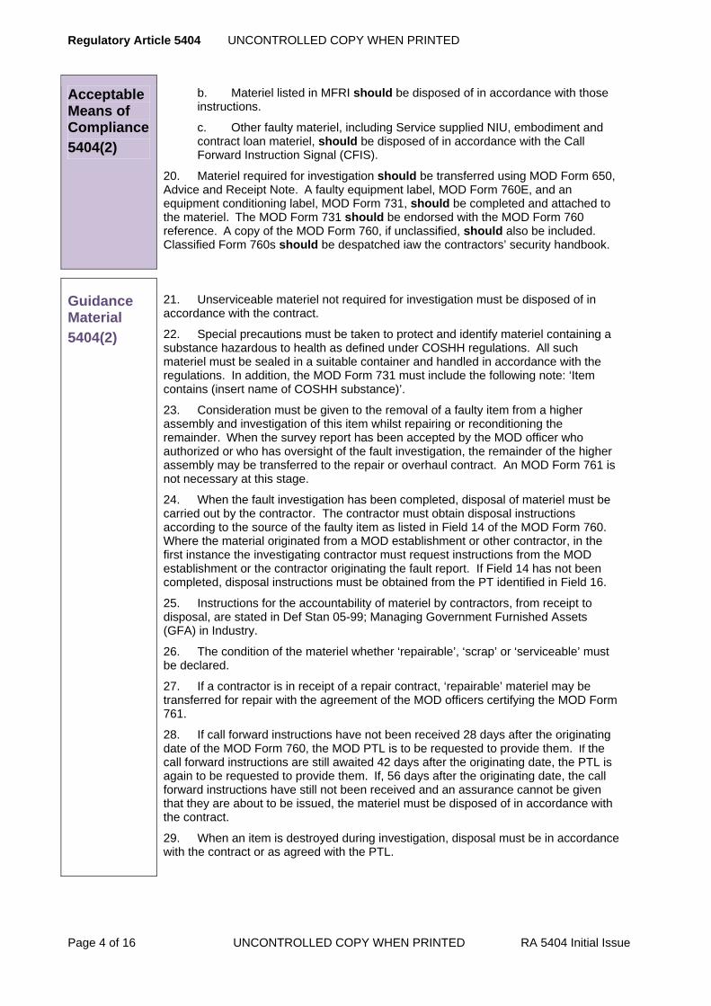
Regulatory Article 5404 UNCONTROLLED COPY WHEN PRINTED
Page 4 of 16 UNCONTROLLED COPY WHEN PRINTED RA 5404 Initial Issue
Acceptable Means of Compliance
5404(2)
b. Materiel listed in MFRI should be disposed of in accordance with those instructions.
c. Other faulty materiel, including Service supplied NIU, embodiment and contract loan materiel, should be disposed of in accordance with the Call Forward Instruction Signal (CFIS).
20. Materiel required for investigation should be transferred using MOD Form 650, Advice and Receipt Note. A faulty equipment label, MOD Form 760E, and an equipment conditioning label, MOD Form 731, should be completed and attached to the materiel. The MOD Form 731 should be endorsed with the MOD Form 760 reference. A copy of the MOD Form 760, if unclassified, should also be included. Classified Form 760s should be despatched iaw the contractors’ security handbook.
Guidance Material
5404(2)
21. Unserviceable materiel not required for investigation must be disposed of in accordance with the contract.
22. Special precautions must be taken to protect and identify materiel containing a substance hazardous to health as defined under COSHH regulations. All such materiel must be sealed in a suitable container and handled in accordance with the regulations. In addition, the MOD Form 731 must include the following note: ‘Item contains (insert name of COSHH substance)’.
23. Consideration must be given to the removal of a faulty item from a higher assembly and investigation of this item whilst repairing or reconditioning the remainder. When the survey report has been accepted by the MOD officer who authorized or who has oversight of the fault investigation, the remainder of the higher assembly may be transferred to the repair or overhaul contract. An MOD Form 761 is not necessary at this stage.
24. When the fault investigation has been completed, disposal of materiel must be carried out by the contractor. The contractor must obtain disposal instructions according to the source of the faulty item as listed in Field 14 of the MOD Form 760. Where the material originated from a MOD establishment or other contractor, in the first instance the investigating contractor must request instructions from the MOD establishment or the contractor originating the fault report. If Field 14 has not been completed, disposal instructions must be obtained from the PT identified in Field 16.
25. Instructions for the accountability of materiel by contractors, from receipt to disposal, are stated in Def Stan 05-99; Managing Government Furnished Assets (GFA) in Industry.
26. The condition of the materiel whether ‘repairable’, ‘scrap’ or ‘serviceable’ must be declared.
27. If a contractor is in receipt of a repair contract, ‘repairable’ materiel may be transferred for repair with the agreement of the MOD officers certifying the MOD Form 761.
28. If call forward instructions have not been received 28 days after the originating date of the MOD Form 760, the MOD PTL is to be requested to provide them. If the call forward instructions are still awaited 42 days after the originating date, the PTL is again to be requested to provide them. If, 56 days after the originating date, the call forward instructions have still not been received and an assurance cannot be given that they are about to be issued, the materiel must be disposed of in accordance with the contract.
29. When an item is destroyed during investigation, disposal must be in accordance with the contract or as agreed with the PTL.
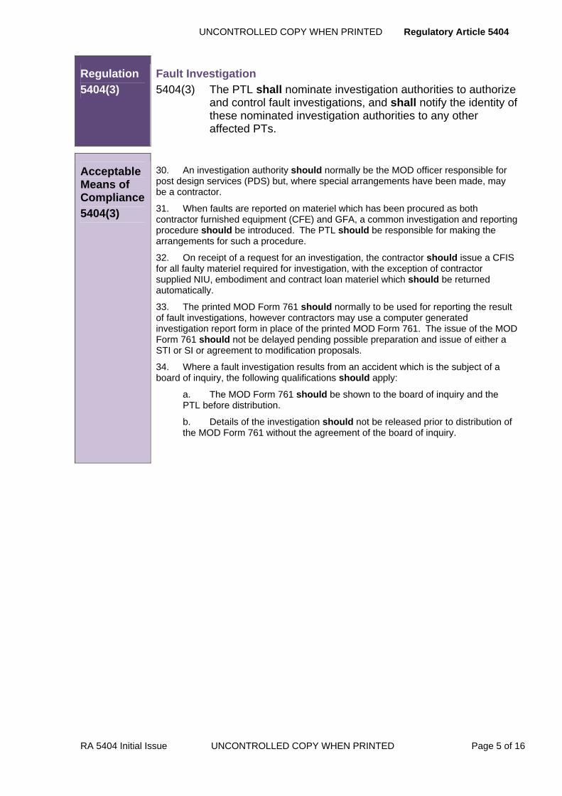
UNCONTROLLED COPY WHEN PRINTED Regulatory Article 5404
RA 5404 Initial Issue UNCONTROLLED COPY WHEN PRINTED Page 5 of 16
Regulation
5404(3)
Fault Investigation 5404(3) The PTL shall nominate investigation authorities to authorize
and control fault investigations, and shall notify the identity of these nominated investigation authorities to any other affected PTs.
Acceptable Means of Compliance
5404(3)
30. An investigation authority should normally be the MOD officer responsible for post design services (PDS) but, where special arrangements have been made, may be a contractor.
31. When faults are reported on materiel which has been procured as both contractor furnished equipment (CFE) and GFA, a common investigation and reporting procedure should be introduced. The PTL should be responsible for making the arrangements for such a procedure.
32. On receipt of a request for an investigation, the contractor should issue a CFIS for all faulty materiel required for investigation, with the exception of contractor supplied NIU, embodiment and contract loan materiel which should be returned automatically.
33. The printed MOD Form 761 should normally to be used for reporting the result of fault investigations, however contractors may use a computer generated investigation report form in place of the printed MOD Form 761. The issue of the MOD Form 761 should not be delayed pending possible preparation and issue of either a STI or SI or agreement to modification proposals.
34. Where a fault investigation results from an accident which is the subject of a board of inquiry, the following qualifications should apply:
a. The MOD Form 761 should be shown to the board of inquiry and the PTL before distribution.
b. Details of the investigation should not be released prior to distribution of the MOD Form 761 without the agreement of the board of inquiry.

Regulatory Article 5404 UNCONTROLLED COPY WHEN PRINTED
Page 6 of 16 UNCONTROLLED COPY WHEN PRINTED RA 5404 Initial Issue
Guidance Material
5404(3)
35. Contract cover is normally provided under PDS contracts. Such cover may extend to the provision of a fault management service, including maintenance of fault data and support to fault meetings, where the amount of materiel in service generates a significant number of fault investigation requests. In other instances cover may be given under local purchase orders (LPOs), delivery, supply, repair or overhaul contracts. Some contractors may elect to investigate within overheads or make other arrangements.
36. A PTL requesting the investigation of a MOD Form 760 report will forward to the investigation authority a MOD Form 760A with Field 1 completed. On receipt, the investigation authority must consider the need for an investigation and complete the MOD Form 760A in Field 2 accordingly.
37. For contractor supplied NIU, embodiment or contract loan materiel where the MOD Form 760 is sent direct to the investigation authority by the reporting contractor or MOD establishment, the investigation authority must consider the need for an investigation, raise a MOD Form 760A and complete Field 2 only.
38. An investigation resulting from a data analysis request must be authorized as for contractor supplied faulty embodiment and contract loan materiel.
39. For a fault reported on a SFS, authorization and investigation will be as specified in the contract.
40. Fault investigation priorities will be determined by the PTL. In principle, the order of priority will be:
a. Accidents.
b. SFS.
c. MOD F760s.
d. Data analysis requests.
41. If the faulty materiel has not been received by the contractor within 28 days of raising the CFIS, the contractor is to notify the PTL. If not received after 56 days the contractor must confirm with the PTL, that the investigation can be closed. The investigation authority who completed Field 2 of the original MOD Form 760A must raise an amended MOD Form 760A recording in Field 2 the closure of the investigation due to non-receipt of the faulty materiel.
42. When an investigation at a contractor's premises reveals that the basic cause of a fault may be a deficiency in another (second) contractor's materiel, ie a consequential fault, the following action must be taken:
a. For Materiel procured by the MOD from the second contractor (GFE), the contractor must refer the matter to the PTL. If there is a suitable contract at the second contractor the investigation will be transferred to that contractor. The second contractor's MOD Form 761 must include the findings of the first contractor's investigation. If there is no suitable contract the contractor may be requested to arrange for investigation as b. below
b. For Materiel procured by the contractor from a second contractor e.g. sub-contractor (CFE), the contractor must arrange for an investigation of the faulty item, normally in conjunction with the second contractor, and for the findings to be included in the prime contractor’s MOD Form 761.
43. The signature of the MOD officer ie MOD Certification (Field 14) means acceptance of the results of the investigation and the proposed remedial action. He will complete (also at Field 14) the statement on whether or not the liability of the contractor, for quality of manufacture/design, is in question by MOD.
44. The format and distribution of investigation reports resulting from data analysis requests must be agreed with the MOD officer authorising the request. A copy of the investigation report must not be sent to Management Information – Engineering
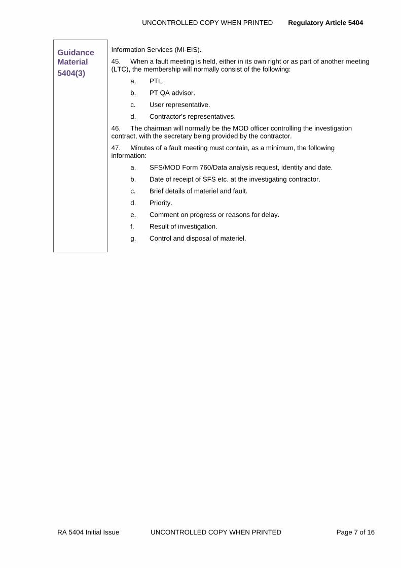
UNCONTROLLED COPY WHEN PRINTED Regulatory Article 5404
RA 5404 Initial Issue UNCONTROLLED COPY WHEN PRINTED Page 7 of 16
Guidance Material
5404(3)
Information Services (MI-EIS).
45. When a fault meeting is held, either in its own right or as part of another meeting (LTC), the membership will normally consist of the following:
a. PTL.
b. PT QA advisor.
c. User representative.
d. Contractor’s representatives.
46. The chairman will normally be the MOD officer controlling the investigation contract, with the secretary being provided by the contractor.
47. Minutes of a fault meeting must contain, as a minimum, the following information:
a. SFS/MOD Form 760/Data analysis request, identity and date.
b. Date of receipt of SFS etc. at the investigating contractor.
c. Brief details of materiel and fault.
d. Priority.
e. Comment on progress or reasons for delay.
f. Result of investigation.
g. Control and disposal of materiel.
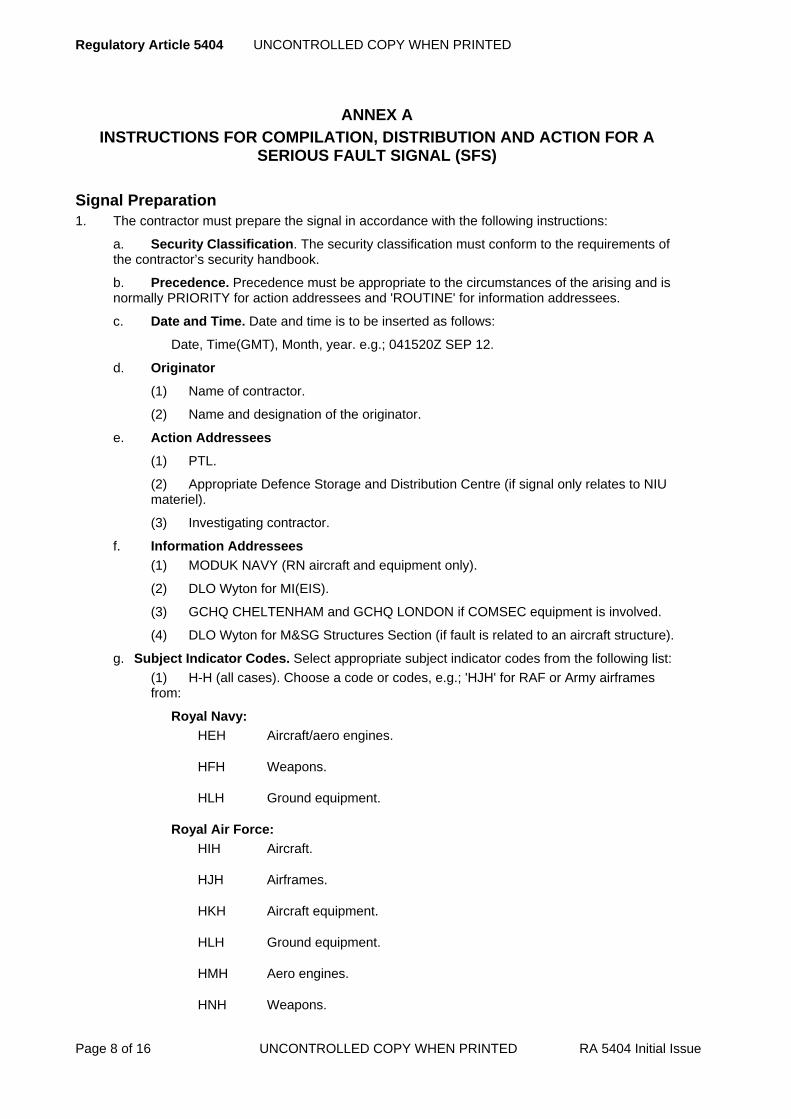
Regulatory Article 5404 UNCONTROLLED COPY WHEN PRINTED
Page 8 of 16 UNCONTROLLED COPY WHEN PRINTED RA 5404 Initial Issue
ANNEX A
INSTRUCTIONS FOR COMPILATION, DISTRIBUTION AND ACTION FOR A SERIOUS FAULT SIGNAL (SFS)
Signal Preparation 1. The contractor must prepare the signal in accordance with the following instructions:
a. Security Classification. The security classification must conform to the requirements of the contractor’s security handbook.
b. Precedence. Precedence must be appropriate to the circumstances of the arising and is normally PRIORITY for action addressees and 'ROUTINE' for information addressees.
c. Date and Time. Date and time is to be inserted as follows:
Date, Time(GMT), Month, year. e.g.; 041520Z SEP 12.
d. Originator
(1) Name of contractor.
(2) Name and designation of the originator.
e. Action Addressees
(1) PTL.
(2) Appropriate Defence Storage and Distribution Centre (if signal only relates to NIU materiel).
(3) Investigating contractor.
f. Information Addressees
(1) MODUK NAVY (RN aircraft and equipment only).
(2) DLO Wyton for MI(EIS).
(3) GCHQ CHELTENHAM and GCHQ LONDON if COMSEC equipment is involved.
(4) DLO Wyton for M&SG Structures Section (if fault is related to an aircraft structure).
g. Subject Indicator Codes. Select appropriate subject indicator codes from the following list: (1) H-H (all cases). Choose a code or codes, e.g.; 'HJH' for RAF or Army airframes from:
Royal Navy:
HEH Aircraft/aero engines.
HFH Weapons.
HLH Ground equipment.
Royal Air Force:
HIH Aircraft.
HJH Airframes.
HKH Aircraft equipment.
HLH Ground equipment.
HMH Aero engines.
HNH Weapons.
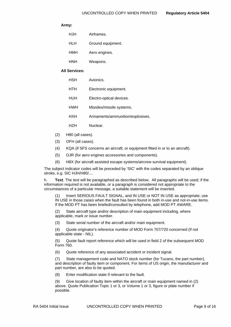
UNCONTROLLED COPY WHEN PRINTED Regulatory Article 5404
RA 5404 Initial Issue UNCONTROLLED COPY WHEN PRINTED Page 9 of 16
Army:
HJH Airframes.
HLH Ground equipment.
HMH Aero engines.
HNH Weapons.
All Services:
HSH Avionics.
HTH Electronic equipment.
HUH Electro-optical devices.
HWH Missiles/missile systems.
HXH Armaments/ammunition/explosives.
HZH Nuclear.
(2) H80 (all cases).
(3) OFH (all cases).
(4) KQA (if SFS concerns an aircraft, or equipment fitted in or to an aircraft).
(5) OJR (for aero engines accessories and components).
(6) H8X (for aircraft assisted escape systems/aircrew survival equipment).
The subject indicator codes will be preceded by ‘SIC’ with the codes separated by an oblique stroke, e.g. SIC HJH/H80/....
h. Text. The text will be paragraphed as described below. All paragraphs will be used; if the information required is not available, or a paragraph is considered not appropriate to the circumstances of a particular message, a suitable statement will be inserted.
(1) Insert SERIOUS FAULT SIGNAL, and IN USE or NOT IN USE as appropriate; use IN USE in those cases when the fault has been found in both in-use and not-in-use items. If the MOD PT has been briefed/consulted by telephone, add MOD PT AWARE.
(2) State aircraft type and/or description of main equipment including, where applicable, mark or issue number.
(3) State serial number of the aircraft and/or main equipment.
(4) Quote originator's reference number of MOD Form 707/720 concerned (if not applicable state - NIL).
(5) Quote fault report reference which will be used in field 2 of the subsequent MOD Form 760.
(6) Quote reference of any associated accident or incident signal.
(7) State management code and NATO stock number (for Tucano, the part number), and description of faulty item or component. For items of US origin, the manufacturer and part number, are also to be quoted.
(8) Enter modification state if relevant to the fault.
(9) Give location of faulty item within the aircraft or main equipment named in (2) above. Quote Publication Topic 1 or 3, or Volume 1 or 3, figure or plate number if possible.

Regulatory Article 5404 UNCONTROLLED COPY WHEN PRINTED
Page 10 of 16 UNCONTROLLED COPY WHEN PRINTED RA 5404 Initial Issue
(10) List the following information as applicable - date installed, hours flown or run, number of landings, date of last inspection or servicing’.
(11) Describe the fault or its symptoms. State how the fault was found, its probable cause and effects.
(12) State the number of the items examined at the contractor. If both in-use and not-in-use items have been examined, quote numbers separately.
(13) State the number of the items found faulty at the contractor. If both in-use and not-in-use items have been examined, quote the numbers of each found faulty separately. List the serial numbers, if they have them, of the faulty items.
(14) State the recommended inspection and remedial action. Give an estimate of the man-hours involved. State either RECOMMENDATION ONLY or WORK IN HAND.
(15) Give longer term recommendations, if any.
(16) State the whereabouts of the faulty item. If forwarded include despatch details and consignee.
Action on Receipt of a SFS 2. A PT, on receipt of an SFS, will redistribute to MOD and contractor addressees against a standard distribution list (SDL) provided and maintained by the PTL.
3. D/Flying Engineering will review for any action necessary by MOD establishments.
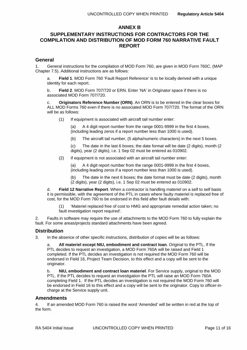
UNCONTROLLED COPY WHEN PRINTED Regulatory Article 5404
RA 5404 Initial Issue UNCONTROLLED COPY WHEN PRINTED Page 11 of 16
ANNEX B
SUPPLEMENTARY INSTRUCTIONS FOR CONTRACTORS FOR THE COMPILATION AND DISTRIBUTION OF MOD FORM 760 NARRATIVE FAULT
REPORT
General 1. General instructions for the compilation of MOD Form 760, are given in MOD Form 760C, (MAP Chapter 7.5). Additional instructions are as follows:
a. Field 1. MOD Form 760 ‘Fault Report Reference’ is to be locally derived with a unique identity for each report.
b. Field 2. MOD Form 707/720 or ERN. Enter ‘NA’ in Originator space if there is no associated MOD Form 707/720.
c. Originators Reference Number (ORN). An ORN is to be entered in the clear boxes for ALL MOD Forms 760 even if there is no associated MOD Form 707/720. The format of the ORN will be as follows:
(1) If equipment is associated with aircraft tail number enter:
(a) A 4 digit report number from the range 0001-9999 in the first 4 boxes, (including leading zeros if a report number less than 1000 is used).
(b) The aircraft tail number, (5 alpha/numeric characters) in the next 5 boxes.
(c) The date in the last 6 boxes; the date format will be date (2 digits), month (2 digits), year (2 digits), i.e. 1 Sep 02 must be entered as 010902.
(2) If equipment is not associated with an aircraft tail number enter:
(a) A 4 digit report number from the range 0001-9999 in the first 4 boxes, (including leading zeros if a report number less than 1000 is used).
(b) The date in the next 6 boxes; the date format must be date (2 digits), month (2 digits), year (2 digits), i.e. 1 Sep 02 must be entered as 010902.
d. Field 12 Narrative Report. When a contractor is handling materiel on a self to self basis it is permissible, with the agreement of the PTL in cases where faulty materiel is replaced free of cost, for the MOD Form 760 to be endorsed in this field after fault details with:
(1) ‘Materiel replaced free of cost to HMG and appropriate remedial action taken; no fault investigation report required’.
2. Faults in software may require the use of attachments to the MOD Form 760 to fully explain the fault. For some areas/projects standard attachments have been agreed.
Distribution 3. In the absence of other specific instructions, distribution of copies will be as follows:
a. All materiel except NIU, embodiment and contract loan. Original to the PTL. If the PTL decides to request an investigation, a MOD Form 760A will be raised and Field 1 completed. If the PTL decides an investigation is not required the MOD Form 760 will be endorsed in Field 16, Project Team Decision, to this effect and a copy will be sent to the originator.
b. NIU, embodiment and contract loan materiel. For Service supply, original to the MOD PTL. If the PTL decides to request an investigation the PTL will raise an MOD Form 760A completing Field 1. If the PTL decides an investigation is not required the MOD Form 760 will be endorsed in Field 16 to this effect and a copy will be sent to the originator. Copy to officer-in-charge at the Service supply unit.
Amendments 4. If an amended MOD Form 760 is raised the word ‘Amended’ will be written in red at the top of the form.

Regulatory Article 5404 UNCONTROLLED COPY WHEN PRINTED
Page 12 of 16 UNCONTROLLED COPY WHEN PRINTED RA 5404 Initial Issue
ANNEX C
INSTRUCTIONS FOR THE COMPILATION AND DISTRIBUTION OF MOD FORM 760A FAULT INVESTIGATION REQUEST
Compilation 1. The compilation and distribution of the MOD Form 760A must be in accordance with the following instructions:
a. Field 1. Support/Engineering Authority/Integrated Project Team Investigation Request and Field 3 - Support/Engineering Authority/Integrated Project Team Follow-Up Action. These fields must not be used by contractors.
b. Field 2. Investigation Authority Action:
(1) This field will be completed by contractors, when they have delegated financial authority
(2) The Task No. is limited to the last 6 characters (this is for computer entry purposes).
(3) Include under Additional Instructions/Remarks a statement that a Call Forward Instruction Signal will/will not be issued.
c. Change of decision. If there is a change of decision this will be notified by the distribution of an amended MOD Form 760A. ‘Amended’ will be written in red at the top of the form.
Distribution
2. The MOD Form 760A, with Field 2 completed, will be distributed as follows:
a. Original to the PTL.
b. Investigation agency tasked with a copy of the MOD Form 760.
c. D Log (Strike) MI(EIS).
d. Originator.
e. Originator’s Front Line Command.

UNCONTROLLED COPY WHEN PRINTED Regulatory Article 5404
RA 5404 Initial Issue UNCONTROLLED COPY WHEN PRINTED Page 13 of 16
ANNEX D
INSTRUCTIONS FOR THE COMPILATION AND DISTRIBUTION OF A CALL FORWARD INSTRUCTION SIGNAL
1. The contractor must prepare the signal in accordance with the following instructions:
a. Security Classification. The security classification must conform to the requirements of the contractors security handbook.
b. Precedence. Precedence must be appropriate to the circumstances of the fault, normally ROUTINE for action and information addressees.
c. Date and Time. Date and time is to be inserted as follows:
Date, Time(GMT), Month, year. e.g.; 041520Z SEP 12.
d. Originator of the Call Forward Instruction Signal
(1) Name of contractor.
(2) Name and designation of the originator.
e. Action Addressees
(1) Service unit/MOD establishment/contractor holding the faulty materiel (normally the originator of the MOD Form 760).
NOTE Where a Service unit is the action addressee a telex may be routed through the Service signals ‘gateway station’ at RAF Boddington, Telex Number 437143, with the following preamble at the start of the text:
‘RAF Boddington is requested to re-transmit to (unit name)’
f. Information Addressee. PTL
g. Subject Indicator Codes. H-H as selected in accordance with Annex A, para 1.g.(1).
h. Text. The text will be paragraphed as follows:
(1) Insert CALL FORWARD INSTRUCTION FOR FAULTY EQUIPMENT.
(2) MOD Form 760 reference and date.
(3) Description of faulty materiel.
(4) Section and reference, NATO stock number or part number, or if US origin manufacturer and part number.
(5) Serial number.
(6) Address where faulty equipment is to be sent.
(7) Name appointment/department of intended recipient.
(8) Investigation task number.
(9) Contract number.
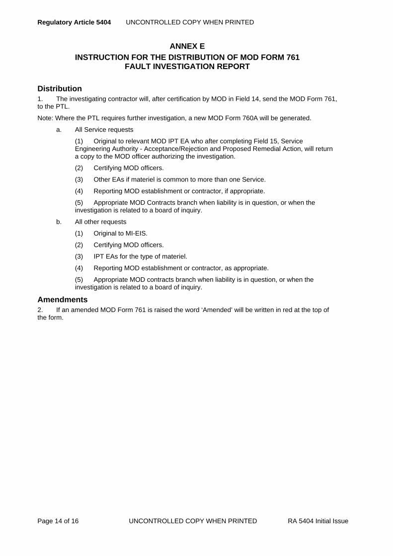
Regulatory Article 5404 UNCONTROLLED COPY WHEN PRINTED
Page 14 of 16 UNCONTROLLED COPY WHEN PRINTED RA 5404 Initial Issue
ANNEX E
INSTRUCTION FOR THE DISTRIBUTION OF MOD FORM 761 FAULT INVESTIGATION REPORT
Distribution 1. The investigating contractor will, after certification by MOD in Field 14, send the MOD Form 761, to the PTL.
Note: Where the PTL requires further investigation, a new MOD Form 760A will be generated.
a. All Service requests
(1) Original to relevant MOD IPT EA who after completing Field 15, Service Engineering Authority - Acceptance/Rejection and Proposed Remedial Action, will return a copy to the MOD officer authorizing the investigation.
(2) Certifying MOD officers.
(3) Other EAs if materiel is common to more than one Service.
(4) Reporting MOD establishment or contractor, if appropriate.
(5) Appropriate MOD Contracts branch when liability is in question, or when the investigation is related to a board of inquiry.
b. All other requests
(1) Original to MI-EIS.
(2) Certifying MOD officers.
(3) IPT EAs for the type of materiel.
(4) Reporting MOD establishment or contractor, as appropriate.
(5) Appropriate MOD contracts branch when liability is in question, or when the investigation is related to a board of inquiry.
Amendments 2. If an amended MOD Form 761 is raised the word ‘Amended’ will be written in red at the top of the form.

UNCONTROLLED COPY WHEN PRINTED Regulatory Article 5404
RA 5404 Initial Issue UNCONTROLLED COPY WHEN PRINTED Page 15 of 16
ANNEX F
PACKAGING FAULTS - REPORTING AND INVESTIGATION
General Policy 1. The three Services use varying procedures for the reporting and investigation of faults in packaging e.g.: Defective Packaging of Equipment – Reporting Procedures (JSP 336 Vol 13 Leaflet UT7/2) and Material Accounting and Storekeeping Manual (BR 96A Article 1804).
2. Agreement has been reached with the Services that the following procedure will apply when contractors are required to report or investigate packaging faults.
Reporting Packaging Faults 3. Contractors and MOD establishments must report faults in packaging using Serious Fault Signal (SFS)/MOD Form 760 as appropriate noting any of the following special conditions which may apply:
a. Damage to materiel resulting from faulty packaging.
b. Discrepancy, either in quantity or description, between the contents of the package and the package markings.
c. For constructive criticism of package specification, highlighting examples of faulty package design which is considered to be either over-elaborate or inadequate.
4. Fault reporting action is not only intended to cover faulty packaging apparent on receipt of materiel, but also faulty packaging revealed after materiel has been held in store for any period. Packaging failures may have a bearing on the following:
a. Materiel which has deteriorated in store.
b. Materiel found to be faulty in store or in use.
5. The distribution of packaging SFS/MOD Form 760 must be in accordance with this section.
Investigation of Packaging Faults 6. When SFS/MOD Form 760 is received the investigation and distribution arrangements must be in accordance with this chapter. When reports under Defective Packaging of Equipment – Reporting Procedures (JSP 336 Vol 13 Leaflet UT7/2) and Material Accounting and Storekeeping Manual (BR 96A Article 1804) are received the format and distribution of the investigation reports must be agreed with the MOD officer authorising the investigation.

Regulatory Article 5404 UNCONTROLLED COPY WHEN PRINTED
Page 16 of 16 UNCONTROLLED COPY WHEN PRINTED RA 5404 Initial Issue
Intentionally left blank for print pagination

UNCONTROLLED COPY WHEN PRINTED Regulatory Article 5405
RA 5405 Issue 2 UNCONTROLLED COPY WHEN PRINTED Page 1 of 6
►This RA has been substantially re-written; for clarity no change marks are presented – please read RA in entirety◄
RA 5405 – Special Instructions (Technical)
Rationale When a fault or potential fault impairs the safety, serviceability or operational efficiency of Service aircraft, air launched guided weapons, and associated equipment, temporary instructions are issued to authorize urgent remedial action. These instructions, known as Special Instructions (Technical) (SI(T)), are issued by, or on behalf of, the PT, to undertake a work package to identify, monitor, repair or prevent the occurrence or re-occurrence of a potential fault.
Contents 5405(1): Special Instructions (Technical)
Regulation
5405(1)
Special Instructions (Technical) 5405(1) Prior to issuing a SI(T), the TAA shall ensure the effects of
the SI(T) on the aircraft and / or equipment Safety Assessment, Release To Service (RTS), handling and operation, and the Aircraft Document Set (ADS) are assessed.
Acceptable Means of Compliance
5405(1)
Special Instructions (Technical) PT Responsibilities
1. The PT should take responsibility for:
a. Ensuring the Service units are able to fulfil the requirements of an instruction. This includes checking the accuracy of reference numbers, management code numbers, NATO Stock Numbers, etc. (supplying them as necessary), and verifying availability of items required from stores.
b. Consultation with Service Supply Management Branches (SMBs) to ensuring the Service units are able to fulfil the requirements of an instruction and of and the implications of applying the instructions to stored equipment.
c. Initiation of follow-up action involving Aircrew Publications (including Maintenance Schedules) and modifications.
d. Liaison with other PTs and Service non-destructive testing (NDT) authorities.
e. Agreeing new categories and the particular category for an individual instruction.
f. Advising where instructions are to be cancelled.
2. The PT should conduct a review of the Safety Assessment when issuing SI(T). This review should consider both the effect on the aircraft or equipment safety case / assessment(s), as appropriate, of the fault or potential fault being addressed by the SI(T) and any effect that SI(T) compliance itself could introduce (for example, an SI(T) that requires the frequent disturbance of a critical aircraft system, could itself, introduce a risk to life).
3. The PT should engage with the Release to Service Authority (RTSA) during the production of SI(T) to ensure sufficient evidence is made available to enable changes to be incorporated into the RTS.
4. The work of preparation or approval of an SI(T) should be authorized by the

Regulatory Article 5405 UNCONTROLLED COPY WHEN PRINTED
Page 2 of 6 UNCONTROLLED COPY WHEN PRINTED RA 5405 Issue 2
Acceptable Means of Compliance
5405(1)
PTL. Specific conditions are considered in the Guidance Material.
5. When a NDT technique is required to satisfy an SI(T), the relevant PT should be notified as early as possible to enable the appropriate authority to develop the required technique.
6. Armament Safety. Special clearance procedures should be identified before an SI(T) is issued which affects aircraft, weapons or equipment, which have an RTS covering an armament capability.
7. The PT should provide OC HS with a draft copy of the SI(T) to enable him to determine whether operation or handling are affected and, if necessary, provide the wording for a MOD Form 703A1 or MOD Form 703A2 entry.
8. Where an SI(T) affects the aircraft or equipment configuration, the documentation that supports the configuration control should be updated.
Design Organization (DO) Responsibilities
9. The DO should be responsible for the following:
a. Preparing the draft SI(T).
b. Advising the PT of the need for NDT.
c. Recommending acceptance of SI(T) drafted by other DOs, or by the Services.
d. Initiating modification, drawing amendment, Air Publication (AP) amendment or other action to enable cancellation of the SI(T).
e. Providing technical approval.
f. Obtaining TAA or Commodity PTL approval.
g. Preparing SI(T) for issue, and passing to PT for printing and distribution.
Guidance Material
5405(1)
Special Instructions (Technical) General
10. A SI(T) is applicable to materiel held at MOD and contractor establishments.
11. SI(T) are of two main types:
a. Those raised where DO input is required:
(1) Special Technical Instructions (STI) where remedial action is non-recurrent.
(2) Servicing Instructions (SI) where remedial action is recurrent.
b. Those raised where DO input is not required (but DO activity may result); these are known as Service Issued Instructions (SII):
(1) Urgent Technical Instructions (UTI) where remedial action is necessary within 14 days/25 flying hours or less.
(2) Routine Technical Instructions (RTI) for less urgent actions.
12. SI(T) are issued in specific equipment categories as listed in MAP Chapter 10.5.2.
13. The layout of SI and STI are to be in accordance with MAP Chapter 10.5.4 and the preparation of SI and STI is detailed in Annex A.
14. The layout of UTI and RTI are to be in accordance with MAP Chapter 10.5.5.
a. Where the text of an instruction has been agreed by the DO, the PT may issue it by signal if this is necessary to meet Service priorities. A follow up instruction is then distributed in the usual way.
General Outline of the SI/STI System
15. The Issuing Authority (IA) is the organization responsible for authorising the
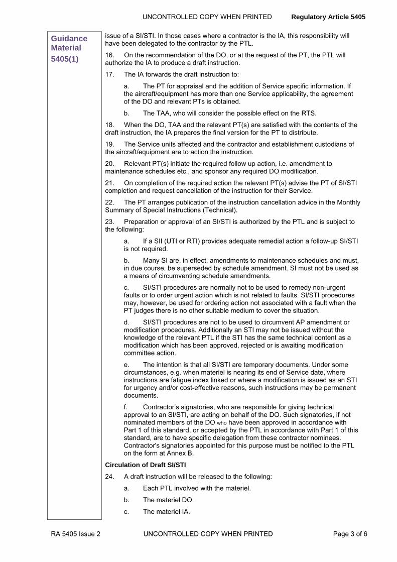
UNCONTROLLED COPY WHEN PRINTED Regulatory Article 5405
RA 5405 Issue 2 UNCONTROLLED COPY WHEN PRINTED Page 3 of 6
Guidance Material
5405(1)
issue of a SI/STI. In those cases where a contractor is the IA, this responsibility will have been delegated to the contractor by the PTL.
16. On the recommendation of the DO, or at the request of the PT, the PTL will authorize the IA to produce a draft instruction.
17. The IA forwards the draft instruction to:
a. The PT for appraisal and the addition of Service specific information. If the aircraft/equipment has more than one Service applicability, the agreement of the DO and relevant PTs is obtained.
b. The TAA, who will consider the possible effect on the RTS.
18. When the DO, TAA and the relevant PT(s) are satisfied with the contents of the draft instruction, the IA prepares the final version for the PT to distribute.
19. The Service units affected and the contractor and establishment custodians of the aircraft/equipment are to action the instruction.
20. Relevant PT(s) initiate the required follow up action, i.e. amendment to maintenance schedules etc., and sponsor any required DO modification.
21. On completion of the required action the relevant PT(s) advise the PT of SI/STI completion and request cancellation of the instruction for their Service.
22. The PT arranges publication of the instruction cancellation advice in the Monthly Summary of Special Instructions (Technical).
23. Preparation or approval of an SI/STI is authorized by the PTL and is subject to the following:
a. If a SII (UTI or RTI) provides adequate remedial action a follow-up SI/STI is not required.
b. Many SI are, in effect, amendments to maintenance schedules and must, in due course, be superseded by schedule amendment. SI must not be used as a means of circumventing schedule amendments.
c. SI/STI procedures are normally not to be used to remedy non-urgent faults or to order urgent action which is not related to faults. SI/STI procedures may, however, be used for ordering action not associated with a fault when the PT judges there is no other suitable medium to cover the situation.
d. SI/STI procedures are not to be used to circumvent AP amendment or modification procedures. Additionally an STI may not be issued without the knowledge of the relevant PTL if the STI has the same technical content as a modification which has been approved, rejected or is awaiting modification committee action.
e. The intention is that all SI/STI are temporary documents. Under some circumstances, e.g. when materiel is nearing its end of Service date, where instructions are fatigue index linked or where a modification is issued as an STI for urgency and/or cost-effective reasons, such instructions may be permanent documents.
f. Contractor’s signatories, who are responsible for giving technical approval to an SI/STI, are acting on behalf of the DO. Such signatories, if not nominated members of the DO who have been approved in accordance with Part 1 of this standard, or accepted by the PTL in accordance with Part 1 of this standard, are to have specific delegation from these contractor nominees. Contractor's signatories appointed for this purpose must be notified to the PTL on the form at Annex B.
Circulation of Draft SI/STI
24. A draft instruction will be released to the following:
a. Each PTL involved with the materiel.
b. The materiel DO.
c. The materiel IA.

Regulatory Article 5405 UNCONTROLLED COPY WHEN PRINTED
Page 4 of 6 UNCONTROLLED COPY WHEN PRINTED RA 5405 Issue 2
Guidance Material
5405(1)
Responsibilities of Issuing Authorities
25. It is the responsibility of the IA to:
a. Notify the PT of authorized signatories, and any subsequent changes that are made, via the MOD officer responsible for authorizing SI/STI preparation, using the layout defined at Annex B.
b. Maintain a register of serial numbers to be allocated to SI/STIs.
c. Where the IA is the DO, give technical approval.
d. Where the IA is not the DO, obtain the technical approval of the DO.
e. Obtain approval of the appropriate PTL(s).
f. Prepare the final version.
g. Send direct to PT for distribution.
h. Provide the PT with distribution requirements.
Distribution
26. The PT will also distribute, as necessary, to MOD establishments and the Users.
27. A periodic review will be made of distribution requirements
Monthly Summary and Indexes
28. Monthly Summary: Supplied to each recipient of SI/STI. The summary lists all SI(T) issued, extended or cancelled during the previous calendar month.
29. Indexes: Annual Indexes produced by PT for each SI(T) category (except where a topic 2(N/A/R)1 is published) and issued to recipients of the particular category of SI/STI.
Cancellation of SI/STI
30. SI/STI normally require cancellation, against evidence of amendments to documents and/or information that the required action has been taken on all affected materiel. Cancellation can only be promulgated with the agreement of the PT.
31. Typical documents requiring change are:
a. Aircraft/equipment publications.
b. Contractor’s drawings and test schedules.
c. Standard serviceability test.
d. Quality control standards.
32. An SI/STI may be superseded by a later SI/STI.

UNCONTROLLED COPY WHEN PRINTED Regulatory Article 5405
RA 5405 Issue 2 UNCONTROLLED COPY WHEN PRINTED Page 5 of 6
ANNEX A
PREPARATION OF SI/STI
General
1. SIs and STIs are to be written in accordance with the following. The PT in approving drafts is responsible for inserting such detail as the individual service requires.
2. Any associated drawings are to be black ink on transparency, or black on white, and capable of achieving a print to AP illustration standard on ISO A4 or A3 size paper.
3. Margins on SI/STIs and Drawings are to be maintained to permit filing in standard binders and to ensure that information is not lost during copying and by punching. The requirements are based on reproduction of both sides of paper for SI/STI but on the obverse, i.e. single side only, for drawings:
a. Obverse - A 2.5 cm margin is to be allowed on the LEFT hand side of the paper and a 1.0 cm margin allowed on the three other sides.
b. Reverse - A 2.5 cm margin is to be allowed on the RIGHT hand side of the paper and a 1.0 cm margin allowed on the three other sides.
c. No detail is permitted within these margins.
4. Changes to SI/STIs are controlled by the following:
a. Amendments leading to a change in alphabetical suffix.
b. STI amendments are paper alterations, in that initial satisfaction of an STI is not affected by a later amendment. Alteration to the work content of an STI which contains an improved method may be put out as an amended issue of the instruction PROVIDED THAT application of the later method is NOT required if the original version has been satisfied (i.e. the two methods are alternatives and either will fulfil the requirement of the STI, even though the later version may be preferable).
c. Alterations that are amendments in principle but are required to be satisfied, even though an original STI has been recorded, are included in revised text issued as a new STI with a new serial number. Similarly, alterations to the work content and/or periodicity of an SI will call for issue of a new instruction if the revision is so critical that it cannot be deferred until the next 'repetition' application.
d. Amendments to SI/STIs, which are of a minor nature not affecting satisfaction of an instruction, may be issued as page replacements. Changes by handwritten or 'cut and paste' alterations are not acceptable. An amendment will therefore be an issue of a revised page or a complete re-issue of the instruction. A vertical bar in the margin indicates the amended part of the text.
5. Where work is done at various locations, it is necessary to divide the work into parts, e.g. Part A at the aircraft, Part B in the servicing bay.
Terminology
6. The following conventions are to be applied.
a. Spelling and Definitions. The Concise Oxford Dictionary is to be used as the master reference for spelling and the meaning of words in general use. Where spelling alternatives are given, the first is to be used.
b. Abbreviations. Abbreviations in the first instance are to be bracketed and preceded by their full meaning; thereafter the abbreviation may be used. An abbreviation that has more than one meaning is not to be used if there is any possibility of ambiguity.
7. Signs, symbols and abbreviations denoting mathematical operations and constants, symbols for physical quantities, unit symbols, symbols for chemical elements and numerical values are to be quoted in ISO units. All dimensions are to be given in decimals.

Regulatory Article 5405 UNCONTROLLED COPY WHEN PRINTED
Page 6 of 6 UNCONTROLLED COPY WHEN PRINTED RA 5405 Issue 2
ANNEX B ISSUING AUTHORITY APPROVED SIGNATORIES
SI/STI CATEGORY ______________________________________________________________
Please use a separate form for each Category)
ISSUING AUTHORITY Post Design Services (PDS) AUTHORITY (if different)
________________________ __________________________
________________________ __________________________
________________________ __________________________
________________________ __________________________
Name (Capitals)_________________________ Designation _________________________
Signature: _____________________________
Name (Capitals)_________________________ Designation _________________________
Signature: _____________________________
Name (Capitals)_________________________ Designation _________________________
Signature: _____________________________
The above named persons are authorized to sign Special Instructions (Technical) in this Category on behalf of:
Organization: ______________________________
Name (Capitals) ____________________________ Designation _________________________
Signature: ________________________________ Dated _____________________

UNCONTROLLED COPY WHEN PRINTED Regulatory Article 5406
RA 5406 Initial Issue UNCONTROLLED COPY WHEN PRINTED Page 1 of 2
RA 5406 - Aircrew Publications - Contractors Responsibilities
Rationale The Aircrew Publications are the official user publications that provide Service aircrew with information on the technical details, operating instructions, performance and handling characteristics of aircraft. In addition, they also include the recommended operational and emergency procedures. A set of Aircrew Publications is issued for each type of aircraft and, as required, for variants and is promulgated by the Publication Organization on behalf of the PTL.
Contents 5406(1): Aircrew Publications – Contractors Responsibilities
Regulation
5406(1)
Aircrew Publications – Contractors Responsibilities 5406(1) The Contractor shall:
a. Ensure that Aircrew Publications reflect the current build standard of the aircraft, including all Design Organization (DO) modifications. b. Make available to the PTL and the designated Publications Organization (PO) all the relevant information to ensure that the Aircrew Publications continue to reflect the current standard of the aircraft.
Acceptable Means of Compliance
5406(1)
1. The Contractor should maintain the master source material (including all graphics) throughout the life of the aircraft and make this material available ‘on demand’ to MOD.
2. The Contractor should generate appropriate text on ‘Effect on Operation and Handling’ for discussion by the Local Technical Committee (LTC) when an effect on operation and/or handling is identified on the Modifications Proposal Form (MPF).
Guidance Material
5406(1)
3. In the context of this RA the term Aircrew Publications includes Aircrew Manuals (AM), Flight Reference Cards (FRC), Operating Data Manuals (ODM) and Flight Test Schedules (FTS). They may also include, if required, Minimum Equipment Lists (MEL) and Aircrew Landaway Flight Servicing Schedules (ALFSS).
4. The AM also contains descriptions of installed avionics, weapons equipment and associated software, along with information on their operation.
5. The detailed requirements for content and format of the Aircrew Publications are provided in JSP 543 (Defence Technical Documentation – Policy & Requirements), Chapters 14, 15 and 16.
6. This RA is concerned with the Contractor’s responsibilities in relation to the preparation and amendment of Aircrew Publications. RA 1310 addresses the Aircraft Document Set, which includes the Aircrew Publications, in detail.

Regulatory Article UNCONTROLLED COPY WHEN PRINTED
Page 2 of 2 UNCONTROLLED COPY WHEN PRINTED RA Initial Issue
Intentionally Blank for Print Pagination

UNCONTROLLED COPY WHEN PRINTED Regulatory Article 5501
RA 5501 Initial Issue UNCONTROLLED COPY WHEN PRINTED Page 1 of 20
RA 5501 - Issue of MOD Owned Equipment
Rationale It is MOD policy to look to contractors to provide all the equipment necessary for the execution of a contract. In some circumstances however it may be necessary for contractors to be issued with MOD owned equipment. Additionally contractors may wish to obtain MOD equipment for private venture (PV) purposes.
This RA addresses the issue and control of MOD owned equipment supplied to contractors in support of MOD contracts. Spares to support repair and overhaul contracts which are procured against Contractors Repair Supply Procedure (CRSP) are the exception for which Def Stan 05-126 is applicable.
Contents 5501(1): Contractual Entitlement
5501(2): Demand Procedure
5501(3): Return of Equipment
Regulation
5501(1)
Contractual Entitlement 5501(1) A contractor's entitlement to MOD owned equipment, the
terms of issue that apply and the delivery programme shall be stated in the contract.
Acceptable Means of Compliance
5501(1)
1. Arrangements for the receipt, storage and issue of equipment should be in accordance with Def Stan 05-99 and may be subject to surveillance.
2. MOD administers a scheme for items of flying clothing which are special to type or in short supply. Contractors should seek advice from the PTL who will liaise with AES PT.
Guidance Material
5501(1)
Contractual Entitlement 3. The supply of MOD (RAF) managed equipment for PV purposes is covered in Annex A.
4. The term ‘equipment’ used in this RA also covers components, materials, tools and test equipment. Certain definitions in this RA use the term ‘materiel’ in lieu of the term ‘equipment’.
5. The arrangements for the supply of MOD owned equipment are based on the following principles:
a. There must be no delay in work at contractors due to a shortage of MOD owned equipment against an agreed programme.
b. There can be no accumulation of MOD owned equipment at contractors which may, on a balance of priorities, be required elsewhere.
c. There will be a clear visibility of the quantity of MOD assets held at contractors, their current serviceability and use.
6. Reference is made to various forms which the contractor is required to use. These are listed in Annex B.

Regulatory Article 5501 UNCONTROLLED COPY WHEN PRINTED
Page 2 of 20 UNCONTROLLED COPY WHEN PRINTED RA 5501 Initial Issue
Guidance Material
5501(1)
Contractual Entitlement 7. Items will only be provided against contracts once the requirements have been identified, and availability and terms of issue cleared by the relevant PT. The decision of the PTL to include the supply of MOD owned equipment in a contract will be based on one or more of the following factors:
a. The contractor is unable to obtain items commercially and these are available from MOD stocks without detriment to the Services.
b. MOD equipment is surplus to forecast requirements.
c. There is no other means of controlling the design, standardisation, inter-changeability and associated documentation of a new equipment which is being introduced into more than one aircraft type.
d. New and advanced techniques and the possibility of further development require control of assets.
e. Standard ground support equipment (GSE) is required for suitability trials.
f. Equipment is needed for the purpose of testing prototype packages.
g. Short term loan of spares is required to facilitate work on MOD contracts.
h. Equipment is required in connection with an aircraft final conference, or trial installation of a modification.
i. Whether special arrangements are required for security.
8. GSE, other than that referred to in paragraph 8e will normally be supplied on replacement loan terms. For any other type of loan the contractor will be required to maintain the GSE in accordance with maintenance schedules and publications.
Accounting and Care of MOD Equipment issued to Contractors 9. The standard conditions which apply governing the responsibilities of contractors in respect of Government property are set out in the specific contract concerned.
10. Detailed advice and instructions on the care and maintenance of equipment is given at Annex C.
Attractive Equipment 11. Attractive is a term applied to selected materiel which is particularly liable to pilferage or misuse because of its intrinsic value and/or the fact that it is portable and has a ready commercial or domestic use. Particular control must be applied at contractor premises to safeguard MOD assets.
Engine Starter Cartridges 12. These will be issued on prepayment terms. The price includes the cost of transit cases, these being returnable for credit. Empty cartridge cases are to be disposed of as scrap at the premises of the contractor.
Restrictions on the Use of the Equipment 13. All equipment issued on loan terms for MOD purposes is issued under a specific contract. Equipment issued on Contract Support Item loan terms may not be retained beyond the limitations of the original loan period, normally not exceeding 12 months, or transferred to another contract without the authority of the PTL, who will, if the requirement is agreed, pass it to SCS(Customer Services)GFS for final authorisation. Loan charges may apply to any equipment not returned by the due date.
Contract Embodiment Item (CEI) 14. In the special case of explosive items the contractor should additionally comply with any instruction or limitation issued on behalf of the Defence Equipment and Support organization. These currently include, but should not be limited to:

UNCONTROLLED COPY WHEN PRINTED Regulatory Article 5501
RA 5501 Initial Issue UNCONTROLLED COPY WHEN PRINTED Page 3 of 20
Guidance Material
5501(1)
a. For all Services issued explosive stores - any limitation imposed by the Joint Services Munitions Control Register (JSMCR) system managed by the Munitions Incident Database Cell, MOD Abbey Wood, Bristol, BS34 8JH.
b. The above instructions will be issued direct to those contractors holding the affected items.
15. A CEI is an item of materiel provided to a contractor, without charge, for incorporation into an asset under manufacture, production, construction, repair, refurbishment, maintenance, servicing, modification, enhancement or conversion.
16. CEI was formerly referred to as an embodiment loan item (or issue). CEIs can include items issued from the following schemes:
a. Contract Repair Support Stock (CRSS).
b. Contract Repair Supply Procedures (CRSP).
c. Contractors Bonded Stores Schemes (CBSS).
d. Ministry Supplied Materiel (MSM).
17. The overall responsibility for initiating and managing CEI (previously Embodiment Loan) arrangements to support new build and repair rests with the PTL concerned who will identify the CEI items to be provided.
18. Conditions governing the loan of equipment under CEI terms are detailed in SM Form 132 (see Annex D), a copy of which will be attached to each contract as an annex.
19. It is the responsibility of the contractor to notify the appropriate MOD PTL when:
a. CEI items are required to meet MOD contracts at Invitation To Tender (ITT) or initial quote stage;
b. It is wished to obtain additional items under CEI terms. In this case the reason must be stated. Only in exceptional cases will additional items be authorized. When authorized, the additional items will be supplied on repayment terms.
20. Contractors Authorized Holding Levels of CEI Items are set out in SM Form 132 paragraph 3 (see Annex D).
21. Excluded Ranges of CEI Items are detailed in SM Form 132 paragraph 2 (see Annex D).
Rectification of Minor Defects on CEI Items 22. Items issued to contractors which are subsequently found to have superficial defects (e.g. surface corrosion, degradation of surface finish, scratches etc.) will not be rejected without reference to the Authority specified in the contract.
23. If, after examination, the Authority specified in the contract considers rectification action is appropriate, it will provide a statement of work to be undertaken and if agreed, the Authority will issue formal instructions authorizing the contractor to proceed. Such instructions will be issued without prejudice to the liability of MOD or the contractor.
Terms of Issue of Materiel 24. Various terms, conditions or regulations, known as ‘terms of issue’, govern the accounting actions applicable to a particular issue/loan. The terms of issue used in contracts which authorize demands for MOD owned equipment are shown in Def Stan 05-99 and are defined as follows:
Contract Work Item (CWI) 25. The term CWI refers to an item of materiel being worked on in accordance with a MOD contract. It is an item of materiel, temporarily issued to a contractor, without charge and for a specified period. Typically this is for the purpose of undergoing

Regulatory Article 5501 UNCONTROLLED COPY WHEN PRINTED
Page 4 of 20 UNCONTROLLED COPY WHEN PRINTED RA 5501 Initial Issue
Guidance Material
5501(1)
repair, refurbishment, maintenance, servicing, modification, enhancement or conversion, or for the purposes of undergoing inspection or packing, and which is subject to physical return in a specified condition.
26. CWI was formerly referred to as a Contract Loan Item.
Contract Support Item (CSI) 27. The term CSI refers to an item of materiel provided to support work on a CWI in accordance with a MOD contract. It is an item of materiel provided to a contractor for a particular purpose and specified period, with or without charge. It is subject to return in the same condition as issued (fair wear and tear excepted), or is replaced with an identical item as new.
28. CSI was formerly referred to as an Ordinary, Repayment, Prepayment or Replacement Loan Item.
Contract Work Arising (CWA) 29. The term CWA refers to an item of materiel removed from a Contract Work Item, in accordance with the requirements set out in a MOD contract. It was formerly referred to as a “contract loan arising”.
30. A CWA is an item of materiel, which is removed – often as a result of cannibalisation or salvage action - from an existing item. The existing item may then be identified for disposal. If it will be retained, as either a fixed asset or stock item, a CWA item may be:
a. Brought on charge as a CWI pending work completion.
b. Brought on charge and issued as a CEI for embodiment purposes.
c. Brought on charge and retained as a CSI for future use.
Legacy Definitions 31. The definitions of superseded terms which may be referred to and shown in legacy documents are contained in Annex E.
Special Jigs, Tools and Test Equipment (JTTE) 32. The term JTTE refers to specialised tools etc. provided to a contractor in aid of the contract under DefCon 23 or DefCon 611.
Regulation
5501(2)
Demand Procedure 5501(2) The contractor shall raise demands for the authorized
equipment detailed in the contract in accordance with the supply programme agreed with the PTL responsible for the contract.
Acceptable Means of Compliance
5501(2)
Demand Procedure 33. Sub-contractors should be granted ‘self demanding’/’self accounting’ status when this will prove beneficial to the discharge of work under the contract. Requests for such status for the sub-contractor should be made by the contractor to the PTL responsible for the contract and to the Asset Accounting Centre (AAC), Def Stan 05-99 refers.
Submission of Demands 34. Contractors entitled to demand RAF managed equipment on contract embodiment, against a Ministry contract, should forward their demands via the

UNCONTROLLED COPY WHEN PRINTED Regulatory Article 5501
RA 5501 Initial Issue UNCONTROLLED COPY WHEN PRINTED Page 5 of 20
Acceptable Means of Compliance
5501(2)
relevant PTL to:
SCS(Customer Services)GFS L Block, Room L007, Defence Equipment & Support, RAF Wyton, Huntingdon. PE28 2EA. (Telephone 01480 52451 ext 7332: Fax 01480 446323).
35. Demands for issue on Contract Support Items (CSI) should be accompanied by a certificate from the PTL for the contract, to the effect that the equipment required is for the contract quoted and that it cannot be obtained from commercial sources to meet the appropriate timescale at an economical price.
Exceptions to Standard Demand Procedure 36. All demands for items in support of research and development (R&D) and post design services (PDS) contracts should normally be countersigned by the PTL responsible for the contract.
37. Demands for issue on repayment terms (sale) and repayment loan should be forwarded direct to Disposal Service Authority (DSA). These should clearly show the loan duration where appropriate. Replacement loan demands should be forwarded to SCS(Customer Services)GFS through the PTL for confirmation of delivery/loan time scales and verification of authenticity and appropriateness of offered item(s) for MOD use. Replacement loan demands should also quote the contract number and delivery forecast for the replacing item.
38. No demands should be submitted for contract work items. The managing PT will make issues as required.
Replacement Requirements 39. Demands made for replacing discrepancies should be suitably endorsed to that effect. Demands arising from discrepancies discovered on receipt of consignments, e.g. damage etc should be endorsed ‘Replacement for discrepancies reported on Form 445’. Demands arising from items subsequently found to be unserviceable on receipt should be endorsed ‘Replacement demand. Not to be included with bulk demands’. On these occasions, a copy of every MOD Form 650A raised should also be promptly forwarded by the contractor to the PT named in Box 4 of the Appendix to Contract.
Issue Procedure 40. A monthly return of unsatisfied demands should be submitted by the contractor to the appropriate PTL.
Discrepancies 41. Discrepancies found on receipt of a consignment, e.g.: losses or damages, or items found to be unserviceable, should be re-demanded in accordance with paragraph 39.
Disposal Arrangements 42. Disposal instructions for MOD owned equipment should normally be set out in the contract document against which the items are provided. However, in the absence of any such instructions, contractors should apply for instructions for equipment issued on loan, both serviceable and repairable, including those items which are:
a. Surplus to contract requirement, entitlement, or authorized stock holding. Items surplus to contract requirements should be listed by the contractor on Appendix 2 to SM Form 132 and submitted to the Authority for disposal instructions within 3 months of the contract completion date.

Regulatory Article 5501 UNCONTROLLED COPY WHEN PRINTED
Page 6 of 20 UNCONTROLLED COPY WHEN PRINTED RA 5501 Initial Issue
Acceptable Means of Compliance
5501(2)
b. Found on receipt to be of incorrect type, or damaged in transit.
c. CEI items found to be damaged or faulty after being taken on charge.
d. Released after fault investigation.
e. Redundant, as the task for which the item was originally provided is complete.
43. All such equipment should be classified:
a. Serviceable; or
b. Repairable.
44. In all cases, when applying for disposal instructions, the following information should be provided:
a. Section/reference number or NATO stock number.
b. Description.
c. Quantity.
d. Original terms of issue.
e. Contract number.
f. Categorization (see paragraph 40 above).
g. Loan numbers.
h. SCS(Customer Services)GFS task number.
i. Support Management Branch (SMB).
Guidance Material
5501(2)
Demand Procedure 45. Arrangements for contractors entitled to CEI demands are detailed in SM Form 132 paragraph 4 (see Annex D).
46. The demand categories to be used are shown in SM Form 132 paragraph 6.
47. The priority codes to be used are shown in SM Form 132 paragraph 5.
48. CEI demand rejection procedures are set out in SM Form 132 paragraph 8.
49. The progression of demands is set out in SM Form 132 paragraph 9.
50. Action by the contractor when an item becomes critical is set out in SM Form 132 paragraph 10.
Upgrading or Downgrading of the Requirement 51. If a contractor requires an earlier or later supply of an item or items already on demand, a new demand will be submitted (normally by fax) quoting the revised priority code. The original demand must be cancelled and referred to in the new demand to ensure its cancellation. In seeking earlier supply, only the quantities urgently required will be afforded a higher priority and be included in the new demand. A separate demand at a lower priority will be raised for the quantities then remaining.
Reduction of Demand Quantity 52. If it is necessary to reduce the quantity of a demand, the original demand must be cancelled and a new demand raised, cross referenced to the cancelled demand.
Cancellation of Demands 53. If items on demand are no longer required, e.g.: as a result of a modification, SCS(Customer Services)GFS must be advised immediately. Items on priority code 05-13 must be cancelled by telex or fax, and code 16 by post, telex or fax.

UNCONTROLLED COPY WHEN PRINTED Regulatory Article 5501
RA 5501 Initial Issue UNCONTROLLED COPY WHEN PRINTED Page 7 of 20
Guidance Material
5501(2)
54. Demands outstanding or satisfied in part only, are held as inabilities and subject to review after 180 days. At that time, the PT will ask the contractor if he wishes to maintain or cancel the demand. It is essential that such inquiries are answered promptly; otherwise the demand may be cancelled. If the demand will be maintained, but remains unsatisfied after further specific periods (depending on the type of item concerned) it will be automatically cancelled and the contractor advised accordingly.
Issue Procedures 55. All issues from the RAF Equipment Supply Depot (ESD) will be made on a computer produced issue voucher, RAF Form 600 ESD, which consists of red, purple and black copies. This is a single line voucher, confined to one vocabulary item. The red (packing) copy will accompany the equipment. On receipt of the equipment the red copy will be retained. The purple copy is for ESD internal use only, and any such copies inadvertently sent to a contractor must be returned to the consignor ESD marked ‘For the attention of Officer Commanding Freight Distribution Squadron’ (OC FDS).
56. Where inabilities are notified, but the priority does not warrant a diversion order, the contractor may, if necessary, request the PTL to arrange for ‘direct delivery’ from the manufacturing contractor. The PT will subsequently issue instructions and advise the contractor of the action taken.
57. Serially numbered issue transaction sheets (ITS) are produced weekly by the issuing RAF ESDs for use by defence contractors. They are in two forms:
a. Firstly, ITS records the issue transactions cleared by the ESD during the previous few weeks. Each transaction is annotated with a terms of issue code which allows transactions to be identified.
b. Secondly, an ITS may be produced 49 days after the original issue voucher has been produced if no dispatch details are available at the ESD. This ITS will allow contractors to verify the receipt of demanded items, or to take discrepancy reporting action, using MOD Form 445 as necessary. Both versions of ITS are for retention by the contractor.
58. Issues from RAF units will be made on an issue voucher, RAF Form 603. Five copies are produced and are distributed as follows:
a. Copy No 1 - is retained by the issuing unit.
b. Copy No 2 - is the issue copy and will accompany the equipment for retention by the contractor.
c. Copy No 3 - is the advice copy and is forwarded to the contractor by post in advance of the equipment. It will be returned to the issuing unit with receipt details completed by the contractor.
d. Copy No 4 - is the Asset Accounting Centre (AAC) copy and must be sent to:
DE&S/AAC 12th Floor, West Point, 501 Chester Road, Old Trafford, Manchester.
M16 9HU.
e. This is a supplementary copy only.
59. Issue transaction sheets are not produced for issues from units and it is important that contractors return the receipted Copy No 3 to the issuing unit without delay in order to avoid nugatory hastening.

Regulatory Article 5501 UNCONTROLLED COPY WHEN PRINTED
Page 8 of 20 UNCONTROLLED COPY WHEN PRINTED RA 5501 Initial Issue
Disposal Arrangements 60. Where not provided for in the contract, requests for disposal instructions, other than those for equipment which has been the subject of a fault investigation, are to be forwarded in writing to SCS(Customer Services)GFS.
61. Requests for disposal instructions, for equipment which has been the subject of fault investigation, will be in accordance with the 5400 series.
Regulation
5501(3)
Return of Equipment 5501(3) When being returned, equipment bearing standard reference
numbers (including NATO and/or Federal stock numbers) shall be clearly identified and labelled as serviceable or repairable using MOD Form 731; Equipment conditioning label. For broached consumables, RAF Form 3910 shall be used.
Acceptable Means of Compliance
5501(3)
62. Consumable stores in their original unbroached packets should not be accompanied by either MOD Form 731 or RAF Form 3910. Depot loan number details should be provided.
63. Inner containers should contain items of one vocab. sub-section only, and particulars of the sub-section number and/or NATO stock number should be clearly and prominently marked on the outside of each case. All old labels and address markings on cases should be obliterated.
64. To avoid damage in transit, the greatest care should be exercised in packing and loading. Special-to-contents (STC) cases should be used for both serviceable and repairable equipment. If suitable cases are not available at contractors works, they should be demanded from the appropriate Service depot. Where no STC cases can be supplied, every effort should be made by the contractor to provide equipment with adequate alternative protection against transit damage. The consignee details should be clearly marked on packages or cases and included in the address of the accompanying vouchers.
Guidance Material
5501(3)
65. Normally equipment no longer required will be returned to an RAF main storage depot for possible use elsewhere in the Service. However, if the equipment is no longer required by the Service, the PT will issue the contractor with disposal instructions in accordance with current procedures.
66. Extreme care must be exercised when returning empty transit cases for explosives to ensure that no ‘live’ explosives are included in the consignment. All markings and labels are to be obliterated.
67. MOD Form 650, Contractors advice and receipt note, or any such document as the contractor may be authorized to use by AAC for returning equipment, are to be enclosed in the relevant packing cases, or when consignments of large individual items are not packed but dispatched loose in vehicles, carried by the driver.
68. Application may be made to the relevant DSCOM point of contact, in respect of air and surface transportation.
UNCONTROLLED COPY WHEN PRINTED Regulatory Article 5501
RA 5501 Initial Issue UNCONTROLLED COPY WHEN PRINTED Page 9 of 20
ANNEX A PURCHASE OF MOD MANAGED EQUIPMENT FOR PRIVATE VENTURE (PV)
PURPOSES
A.1 Contractors who wish to purchase MOD(RAF) managed equipment, including equipment held under CRSP arrangements, for PV purposes must write, telex or fax their requirement to the address below (copy to the PTL responsible for equipment already held) quoting full reference number, NATO stock number or Federal stock number (as appropriate), part number, description, quantity required, ultimate country of destination and the reason why the equipment is not available from commercial sources:
Ministry of Defence DSA Ops4D, Defence Equipment and Support, Building 86A, RAF Wyton, Huntingdon, Cambridgeshire. PE28 2EA.
A.2 In the case of export orders the country of final destination will be stated.
Regulatory Article 5501 UNCONTROLLED COPY WHEN PRINTED
Page 10 of 20 UNCONTROLLED COPY WHEN PRINTED RA 5501 Initial Issue
ANNEX B LIST OF FORMS
The following forms are all obtainable from:
Forms & Publications HO DSDA Bldg C16 C Site, Ploughly Rd Lower Arncott Oxon OX25 1LP
Form No: Title
MOD Form 445 Discrepancy Report
MOD Form 650 Contractors Advice and Receipt Note
MOD Form 650A Contractors Advice of Equipment Scrapped on Site or Lost in Shops
MOD Form 651 Notification of Government Owned Equipment Rejected or Lost after Issue
MOD Form 731 Equipment Conditioning Label
RAF Form 600S Demand for RAF Equipment
RAF Form 600 Multi Demand for RAF Equipment
RAF Form 3910 Stores Identification Label
PE(SA2) Form 749 Schedule of Stocktaking Discrepancies
PE(SA2) Form 750 Stocktaking Sheet
UNCONTROLLED COPY WHEN PRINTED Regulatory Article 5501
RA 5501 Initial Issue UNCONTROLLED COPY WHEN PRINTED Page 11 of 20
ANNEX C
CARE AND MAINTENANCE OF MOD OWNED EQUIPMENT
C.1 General
C.1.1 Except when subject to special arrangements, equipment issued on loan to contractors is supplied in a serviceable condition and the responsibility for maintaining it in this condition until returned to any MOD Establishment rests with the contractor.
C.1.2 The contractors' arrangements for the maintenance and storage of MOD owned equipment may be subject to surveillance.
C.1.3 The materiel accounting procedure to be followed when issued equipment is found to have faults, has suffered damage, or has become lost, will be notified to the contractor by the Asset Accounting Centre (ACC).
C.1.4 Equipment found to be physically damaged on receipt will be treated as a discrepancy and actioned accordingly. Equipment found to be unserviceable, either by failing standard serviceability testing or during subsequent operation, will be reported in accordance with the procedures stated in RA5404.
C.1.5 MOD owned equipment will be stored, packaged, transported, operated, serviced and maintained in accordance with the appropriate aircraft/equipment publication. Contractors not in receipt of the applicable publication must seek advice from the Authority specified in the contract.
C.1.6 Equipment which is easily detachable from its container/fitment, or is considered to be of a security sensitive nature is only to be fitted when required by the PTL and for the following purposes:
a) For checking the design of the accommodation provided for the equipment and the parts to which it fits.
b) For the final mock-up conference.
c) For flight trials.
d) For the delivery flight of the aircraft.
C.1.7 Such equipment must be removed and returned to the contractors store immediately after use unless alternative arrangements are approved by the PTL.
C.1.8 Equipment having a restricted shelf life is not to be authorized for use when the permitted shelf life has expired. Where however, the storage category of the equipment is such that its life may be extended as a result of inspection, servicing, exercising or testing, and the MOD PTL considers the contractor competent to undertake the work, the life of the equipment may be extended for the specified period subject to it satisfying the standard serviceability test in accordance with the appropriate Air Publication.
C.1.9 Any equipment which becomes superficially wetted from any cause whatsoever will be carefully dried and cleaned, but if the equipment has been completed immersed in water advice will be sought from the PTL on the action to be taken.
C.2 Packaging
C.2.1 All equipment delivered to the Contractor, will be packaged either:

Regulatory Article 5501 UNCONTROLLED COPY WHEN PRINTED
Page 12 of 20 UNCONTROLLED COPY WHEN PRINTED RA 5501 Initial Issue
a) In normal commercial packaging or in a transit case.
b) Preserved, identified and packaged to the Full Standard. In this case the pack will be marked ‘Not to be opened until required’.
C.2.2 Equipment received in an unsealed container will be examined on receipt, after which it will be replaced in the container until required.
C.2.3 Sealed containers are to be examined on receipt. If the container is inadequately identified, shows signs of serious damage or the sealing has been broken, it will be opened immediately and the contents examined. (Where the contents are damaged, or a discrepancy is evident, refer to C.1.4). The container will be carefully re-packed after examination.
C.2.4 If the sealed container is undamaged it must not be opened until shortly before the contents are required. In this case the 14 day period of notification to the Authority, as stated in DefCon 611, will be counted from the date the container is opened.
C.3 Transport
C.3.1 Except when being used or fitted, equipment received in specialised containers are to be stored and transported in these containers mounted and properly secured.
C.3.2 All equipment, whether serviceable or unserviceable, which is being returned, will be packed to a standard equivalent at least to that in which it was received.
C.4 Handling
C.4.1 Care must be exercised when handling equipment, whether in storage or during installation and any applicable special instructions or precautions are to be strictly observed.
C.4.2 Protective covers/blanks must not be removed until necessary.

UNCONTROLLED COPY WHEN PRINTED Regulatory Article 5501
RA 5501 Initial Issue UNCONTROLLED COPY WHEN PRINTED Page 13 of 20
ANNEX D
SPECIMEN SM FORM 132 SM FORM 132 (Nov 99) Annex to Contract No:
STATEMENT OF EMBODIMENT LOAN (EL) REQUIRMENTS IN SUPPORT OF A MOD CONTRACT
Issue of Government Furnished Equipment (GFE)
1. Entitlement. The Contractor is only entitled to demand and receive items of Government Furnished Equipment (GFE) on Embodiment Loan (EL) as specified within this Contract schedule for use solely in support of this Contract. Approval is given for those items and quantities shown in Appendix 1 to this Annex to be demanded on EL terms in accordance with the following terms and conditions.
2. Excluded Ranges. In the event of a delay being caused to new production or repair output by the inability to obtain commercially any item in the excluded ranges, the Contractor must consult with the Project Officer named in Box 2 in the Appendix to this Contract (DEF FORM 111) and negotiate possible RAF supply on repayment terms. Any requests must be submitted to DSA/Ops4D, Room 59, Bldg 86A RAF Wyton, Huntingdon, Cambs, PE28 2EA (Telephone: 01480 52451 x 7095, Facsimile: 01480 446342).
3. Authorized Spares Holding Levels. Contract holdings of EL items are to be restricted to the minimum level specified in the contract:
a) Production Contracts. The Contractor's assets (stock + dues in) of any item must not, without prior approval from SCS(Customer Services)(Air)GFS, exceed that required to meet the production programme over any succeeding 3 month period.
b) Repair Modification/Conversion Contracts.
1) The Contractor's assets (stock + dues in) of any item must not, without prior approval from SCS(Customer Services)(Air)GFS, exceed that required to meet the repair programme over any succeeding 3 month period.
2) The Contractor must assess the quantity required to meet the forward repair programme by applying the following formula:
Forward Requirement = Past 12 months usage X No of major items arising in next 3 months No of major items repaired (Or max. holding period in months)
in last 12 months
Where information on past usage is not available, the Contractor will do the calculation based on his best estimate. This quantity must be shown on the Public Account Stock Record as the maximum asset level.
3) The Contractor must, at the same time, calculate a re-order level. This quantity must be 50% of the quantity calculated at 3 b) 2) above and must be shown on the Public Account Stock Record as the minimum asset level.
4) The Contractor must, on reaching the minimum asset level, recalculate the Forward Requirement minus Assets, and place demands to bring assets up to the maximum asset level. He will also recalculate the minimum level and amend the Public Account Stock Record accordingly.
5) Initial Spares quantities must be calculated as those required to meet the forward programme in the first 3 months of the repair programme.
Regulatory Article 5501 UNCONTROLLED COPY WHEN PRINTED
Page 14 of 20 UNCONTROLLED COPY WHEN PRINTED RA 5501 Initial Issue
4. Demand Procedures. GFE listed on the Schedule must be demanded from SCS(Customer Services)(Air)GFS, Z Block, RAF Wyton, Huntingdon, Cambs. PE28 2EA (Telephone: 01480 52451 x 7231, Facsimile 01480 446323). The Contractor may use either, a 'Demand for RAF Equipment', RAF Form 660S or 600S (MULTI), or facsimile. Whenever a facsimile demand is submitted, the contractor must utilise the following coded format within the body of the message:
From: ...............................................................
To: SCS(Customer Services)(Air)GFS
Security Classification.
(A) RAF Domestic Management Code (DMC) or NATO Stock Number (B) Item Identity Number (C) Description (D) Part Number (E) Denomination of Quantity Code (F) Quantity Required and Condition (G) Priority Code and Required Delivery Date (See paragraph 5) (H) Consignee Identity Code (I) Partner Co and Code (For issues against NETMA contracts only) (J) Demand Category (See paragraph 6) (K) Demand Number (Not to exceed 6 digits) (L) Contract Number (M) Terms of Issue (Use code 'G') (N) Current Embodiment Loan Holdings (See paragraph 7) (O) Remarks
5. Priority Codes. The Contractor must use the following priority codes, as appropriate, to demand equipment according to the standard supply timescales shown.
c) SPC 5 (5) (Supply Chain Processing Time within 24 hours - fastest possible means). Demands on the MOD for materiel required to prevent a work stoppage when SPC 6 would not secure delivery in time.
d) SPC 6 (9) (Supply Chain Processing Time 1-5 working days). When an item is required to avert a work stoppage and non availability would therefore prejudice Service or MOD operations or contract completion.
e) SPC 7 (13) (Supply Chain Processing Time 6-10 working days). When non-availability of an item will jeopardise the contractor's ability to meet contract commitments or when an item is required for support of contract performance on a more urgent basis than stock replenishment.
f) SPC 8 (16) (Supply Chain Processing Time 11-28 working days). When an item is required for stock replenishment or to establish initial operating stocks.
6. Demand Categories. All demands, regardless of the priority code, must show a demand category. The criteria for each category is as follows:
a) Recurring. Spares required for the repair of MOD supplied equipment which has become unserviceable, or to replace an item consumed in use, and where the MOD has a continuing liability to supply.
b) Programme. Demands to support special tasks or new production programmes. Details of unique task/programme serial numbers will be advised to the Contractor by Support Authority (SA).
c) Non-Recurring:
UNCONTROLLED COPY WHEN PRINTED Regulatory Article 5501
RA 5501 Initial Issue UNCONTROLLED COPY WHEN PRINTED Page 15 of 20
1) Demands to form Floats/Pools for specific requirements, e.g. pools of serviceable items which the Contractor can draw from when items removed from the higher assembly undergoing repair, cannot be repaired within the specified repair time of the higher assembly.
2) Demands for complete modification kits or components for modification purposes.
3) Demands for items for which no entitlement exists but for which special authority to demand has been received. (These demands must be concurred by the Project Office and forwarded to the SA for approval and possible contract amendment.)
7. Current Embodiment Loan Holdings. When placing a demand for an item, the Contractor will utilise the format at para 4 and report his current EL holdings (N) for the item requested (A) against the contract specified (L). This will ensure that the Contractor is not exceeding the 3 months authorized spares holding levels for the item concerned, in accordance with paragraph 3.
8. Demand Rejections. Contractor demands for items which are not listed in this Contract, and demands for consumables in the 'Excluded Range' must be rejected by the Authority. In certain circumstances, such as when demand quantities appear excessive, demands for authorized items may be rejected. When a demand is rejected, and the item is still required, the Contractor must provide full supporting details to the Project Manager shown in Box 2 of the Appendix to this Contract (DEFFORM 111).
9. Supply Information. No supply information is given automatically to Contractors. However, when it is essential for work planning, requests for supply information must be made by the Contractor (by telephone or facsimile), to SCS(Customer Services)(Air)GFS.
a) Issues. To confirm that issues against demands coded 8-5 are possible and taking place, information may be requested after the following periods of time have elapsed from when the demand was originally placed: priority 8(16), after 11 working days; priority 7(13), after 7 working days; priority 6(9), after 4 working days; priority 5, after 3 working days.
b) Progression of Demands. Progression of any EL demands must be through SCS(Customer Services)(Air)GFS. When the lack of an EL item is likely to cause the delayed output of a major item from production or repair, the Contractor must report the circumstances to the Project Office shown in Box 2 of the Appendix to this Contract (DEFFORM 111), as soon as the delay is anticipated or becomes known.
10. Critical Items. If the Authority has a critical supply situation in service and stock is held in the EL store, the EL item supply manager may authorize the removal of EL stock items from the Contractor's premises to satisfy this urgent service requirement.
11. Forecasting of EL Requirements. For new production contracts, the Contractor must be required to forecast all anticipated future EL requirements for items required from the RAF as soon as they are identified. For repair, reconditioning and/or modification contracts, the Contractor must be required to forecast those major, sub-assembly and non-consumable spares required to support the contract (known as P and L stores). The EL spares requirements for the Contract concerned must be submitted to the Project Branch shown in Box 2 of the Appendix to this Contract (DEFFORM 111). Where possible, the total forecast must be broken down to show anticipated phased requirements over the contract forecast output period. The forecasting of EL requirements is in addition to, and in confirmation of, any forecast submitted at the tender stage.
12. Issue of Government Property. Detailed requirements on the receipt, maintenance and storage of GFE is given in DefCon 611 - Issued Property. The Contractor will maintain a Register of Issued Property to provide information for the Public Account Stock Record, in accordance with the requirements of DefCon 611 and the Asset Accounting Instructions.
13. Delivery. The Authority will be responsible for delivery to the Contractor of all GFE detailed in Appendix 1 to this Annex, unless other arrangements are specifically detailed elsewhere in the Contract.

Regulatory Article 5501 UNCONTROLLED COPY WHEN PRINTED
Page 16 of 20 UNCONTROLLED COPY WHEN PRINTED RA 5501 Initial Issue
14. Disposal Procedures. The following disposal instructions must apply to EL equipment:
a. Components which become surplus, e.g.: as a result of replacement or incorporation of modifications, or because the aircraft from which they were taken has been re-categorized as beyond economic repair, must be disposed of as indicated at sub-clause 14b) below. Prior to despatch, in accordance with any disposal instructions received, all serviceable and repairable items must be certified as such on Form 731, Equipment Label, by Quality Assurance Representative (QAR) or Authority's Representative. The F650 must be similarly annotated to show the quantities of serviceable and/or repairable items being returned.
b. Disposal procedures for surplus components:
1) Surplus serviceable items must be brought on charge into the Contractor's EL store.
2) Disposal instructions must be requested from appropriate SA or in accordance with the instructions with the instructions specified in the contract. The request must be submitted in the format detailed at Appendix 2 to this Annex. Within 3 months of completion of the contract, all surplus holdings must be reported to the SA, as referred to in RA5501.
3) Parts certified by the Authority's Representative as beyond economic repair must be disposed of as scrap in accordance with the Accounting Letter issued by the Public Accounting Authority specified in Box 8 of the Appendix to this Contract, (DEFFORM 111).
15. Annual Listing of EL Holdings. The Contractor must provide, from the equipment accounting records maintained in accordance with RA5501, to the SA shown in Box 4 of the Appendix to this Contract (DEF FORM 111), on the Contract's anniversary date, a list of all EL items held against the Contract. The following minimum information must be provided with items listed in service stock number sequence: RAF Domestic Management Code or NATO Stock Number, Item Description, Condition of Equipment, Agreed Holding Level, Quantity Held, Estimated Agreed Forward Requirements and Number Surplus to Forward Requirements. In the event of a need for an individual item review between annual listings, the Contractor must provide similar current information on request.

UNCONTROLLED COPY WHEN PRINTED Regulatory Article 5501
RA 5501 Initial Issue UNCONTROLLED COPY WHEN PRINTED Page 17 of 20
APPENDIX 1 TO ANNEX TO CONTRACT NO.
THE FOLLOWING ITEMS ARE AUTHORIZED TO BE DEMANDED ON EMBODIMENT LOAN TERMS FOR USE AGAINST THIS CONTRACT
Ser No
Reference Number
Part Number Description Applicability Qty D of Q PPQ SMBI Comments

Regulatory Article 5501 UNCONTROLLED COPY WHEN PRINTED
Page 18 of 20 UNCONTROLLED COPY WHEN PRINTED RA 5501 Initial Issue
APPENDIX 2 TO ANNEX TOCONTRACT NO.
To: SM(Fin S)2(RAF)/SM(Fin S)4(RAF)* SMG, RAF Wyton
REQUEST FOR DISPOSAL INSTRUCTIONS FOR SURPLUS LOAN ITEMS
Ser No
Reference Number
Part Number
Description Qty Original Terms of Issue
Contract Number
Categorisation (Serviceable/Repairable)
Loan Numbers
SM(Fin S)(RAF) Task Number
SMB
* Delete as applicable; requests for Disposal Instructions for equipment on Ordinary or Embodiment Loan must be submitted to SM(Fin s)4(RAF)
UNCONTROLLED COPY WHEN PRINTED Regulatory Article 5501
RA 5501 Initial Issue UNCONTROLLED COPY WHEN PRINTED Page 19 of 20
ANNEX E
DEFINITION OF SUPERCEDED CATEGORIES
E.1 Definitions
E.1.1 Contract Loan: The temporary issue of materiel for the purpose of it undergoing repair, maintenance, modification, conversion, etc. in accordance with the conditions of the contract.
E.1.2 Embodiment Loan: An issue of materiel, without charge, for embodiment in an article under manufacture, modification, conversion or repair in accordance with the terms of the contract.
E.1.3 Ordinary Loan: An issue of materiel, without charge, for a particular purpose and for a specified period, at the end of which the item is intended to be returned unchanged, except for fair wear and tear.
NOTE Items will only be issued on ordinary loan where the PTL can show it is in the Departments best interests to do so, and the relevant contract specifies the items concerned. Such loans must be for items valued in excess of £1,000 and will not normally exceed 12 months, except where the items are required for a multi-year contract and approval can be given exceptionally for the full contract period (up to 3 years).
E.1.4 Replacement Loan: An issue of materiel to a contractor for which a charge is made either at stated intervals or when the loan is returned. Where a contractor involved in an MOD contract is experiencing production difficulties and delays in respect of an item of his own manufacture, the MOD may authorize a replacement loan from Service or CRSP/embodiment loan stocks. However, replacement loan for items valued under £1,000 will only be authorized where it is considered to be in the Service interest. The contractor undertakes to replace the item loaned with an identical item from new production.
E.1.5 Repayment Loan: A loan of equipment, valued in excess of £1,000, to a contractor for which a charge is made at stated intervals. The period of the loan will be specified, at the end of which the item is intended to be returned with the condition unchanged except for fair wear and tear.
E.1.6 Prepayment Loan (RN only): A loan which is subject to a hire or rental charge payable in advance; a deposit may also be required.
E.1.7 Deferred Acquisition (RN only): Manufacturing tools or equipment which have been provided by a contractor, the full cost of which is borne by the MOD who therefore take disposal rights but not ownership.
E.1.8 Repayment Issue: The authorized issue of materiel, payment for which is made after delivery and credited to public funds.
E.1.9 Prepayment Issue: The authorized issue of materiel, payment for which is received before issue and credited to public funds.
E.1.10 Loan Replacement Issue: Free issue to a contractor to replace an unserviceable item held on repayment or ordinary loan, if the item on loan fails through fair wear and tear and is replaced free of charge. Intentionally Blank for Print Pagination

Regulatory Article 5501 UNCONTROLLED COPY WHEN PRINTED
Page 20 of 20 UNCONTROLLED COPY WHEN PRINTED RA 5501 Initial Issue
Intentionally Blank for Print Pagination

UNCONTROLLED COPY WHEN PRINTED Regulatory Article 5502
RA 5502 Issue 2 UNCONTROLLED COPY WHEN PRINTED Page 1 of 6
►This RA has been substantially re-written; for clarity no change marks are presented – please read RA in entirety◄
RA 5502 - Aircraft Maintenance Forms and Engineering Record Cards
Rationale Aircraft Maintenance Forms (AMF) when assembled and allocated to a specific aircraft provide the means for compiling a complete technical history of the use of that aircraft and a record of its current maintenance state. They are applicable to contracts for the development, production, overhaul, modification or conversion of aircraft and associated equipment.
Engineering Record Cards (ERC) provide permanent technical records of significant events in the life of airframes, aircraft engines and/or modules and other specified equipment. These records are an assurance that the aircraft is maintained in an up-to-date and airworthy state.
Contents 5502(1): Applicability of Aircraft Maintenance Forms and Engineering Record Cards
5502(2): Delivery or Transfer of Aircraft
Regulation
5502(1)
Applicability of Aircraft Maintenance Forms and Engineering Record Cards 5502(1) AMF shall be completed and maintained strictly in
accordance with the index and Instructions for Use promulgated in the relevant MOD Forms.
Acceptable Means of Compliance
5502(1)
Applicability of Aircraft Maintenance Forms and Engineering Record Cards 1. AMF should be used on contracts for development, production, overhaul, modification, and conversion of aircraft and associated equipment. (See Annex A)
2. ERC should be used on contracts for airframes, aircraft engines and/or modules and equipment. (See Annex B)
3. All MOD Form 700 series documents required under the contract should be certified by the contractor's quality manager/chief inspector or a duly authorized member of staff. The contractor should maintain records of all authorized signatories.
4. Before delivery of any item requiring an ERC and before delivery or transfer of any aircraft, the contractor should make all the required MOD Form 700 series documents, completed and certified, available to the relevant Project Team Leader (PTL).
Guidance Material
5502(1)
Applicability of Aircraft Maintenance Forms and Engineering Record Cards 5. All AMF and ERC belong to the MOD Form 700 series of forms.
6. The initial preparation, maintenance and closure of all forms in the MOD Form 700 series for aircraft and equipment produced under MOD contract, including those related to civil types of aircraft and equipment, are the responsibility of the contractor whilst under the contractor's control.
7. The use of MOD Form 707B series (Maintenance Work Order) is optional for contractors unless their use is specified in the contract, or Annex A Clause A.5 applies.
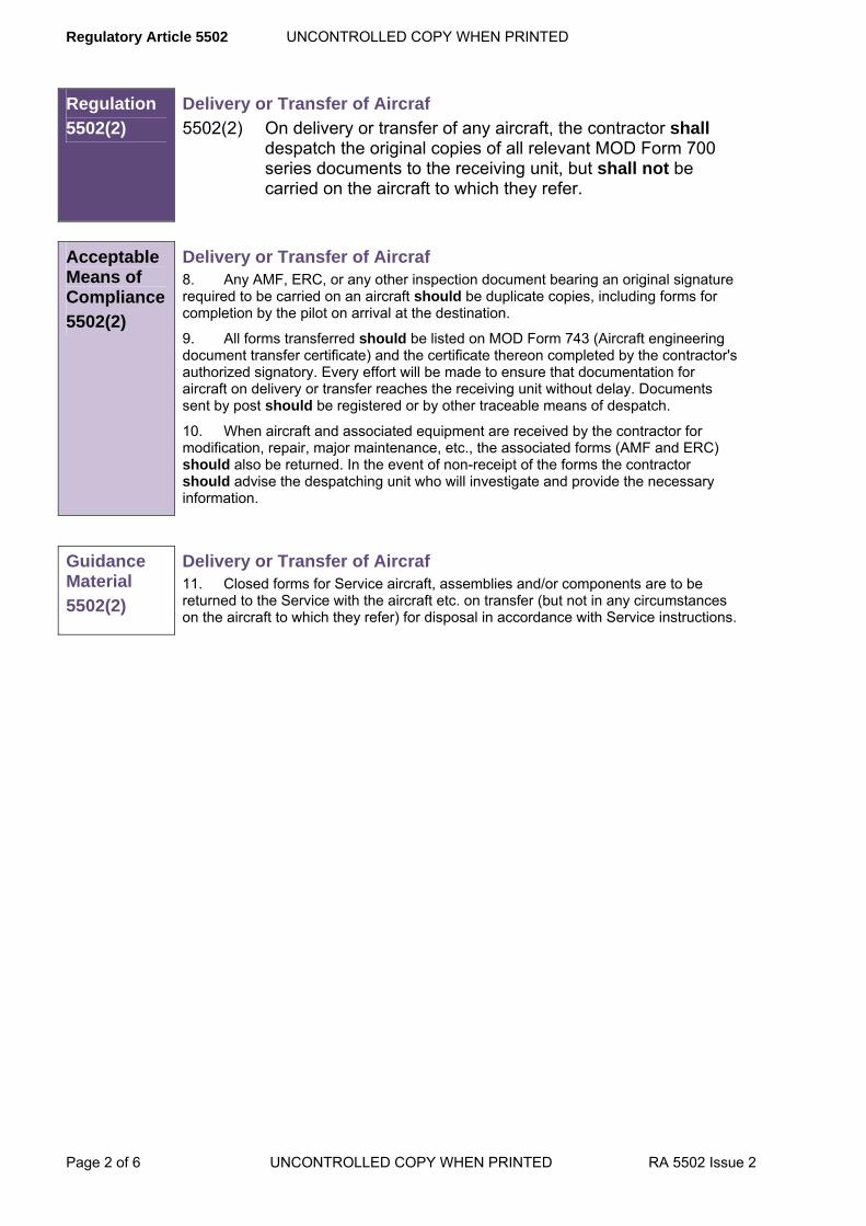
Regulatory Article 5502 UNCONTROLLED COPY WHEN PRINTED
Page 2 of 6 UNCONTROLLED COPY WHEN PRINTED RA 5502 Issue 2
Regulation
5502(2)
Delivery or Transfer of Aircraf 5502(2) On delivery or transfer of any aircraft, the contractor shall
despatch the original copies of all relevant MOD Form 700 series documents to the receiving unit, but shall not be carried on the aircraft to which they refer.
Acceptable Means of Compliance
5502(2)
Delivery or Transfer of Aircraf 8. Any AMF, ERC, or any other inspection document bearing an original signature required to be carried on an aircraft should be duplicate copies, including forms for completion by the pilot on arrival at the destination.
9. All forms transferred should be listed on MOD Form 743 (Aircraft engineering document transfer certificate) and the certificate thereon completed by the contractor's authorized signatory. Every effort will be made to ensure that documentation for aircraft on delivery or transfer reaches the receiving unit without delay. Documents sent by post should be registered or by other traceable means of despatch.
10. When aircraft and associated equipment are received by the contractor for modification, repair, major maintenance, etc., the associated forms (AMF and ERC) should also be returned. In the event of non-receipt of the forms the contractor should advise the despatching unit who will investigate and provide the necessary information.
Guidance Material
5502(2)
Delivery or Transfer of Aircraf 11. Closed forms for Service aircraft, assemblies and/or components are to be returned to the Service with the aircraft etc. on transfer (but not in any circumstances on the aircraft to which they refer) for disposal in accordance with Service instructions.
UNCONTROLLED COPY WHEN PRINTED Regulatory Article 5502
RA 5502 Issue 2 UNCONTROLLED COPY WHEN PRINTED Page 3 of 6
ANNEX A
AIRCRAFT MAINTENANCE FORMS
A.1 Production Aircraft
A.1.1 New AMF in the MOD Form 700 series are to be opened by the contractor for each new aircraft before delivery. For new aircraft types, the appropriate PTL is to advise the contractor concerning the documentation required and will arrange for the supply of provisional copies of any special-to-type forms.
A.1.2 The contractor's own in-house documentation may be used during flight-testing, provided that all salient details relating to test flying are transferred to the relevant AMF before delivery. All AMF are to be complete and up-to-date at the time the aircraft is submitted to the Authority specified in the contract.
A.1.3 The contractor is to enter, in the appropriate replenishment certificates (i.e. MOD Form 705), the quantities of fuel, oil, coolant etc. supplied for the delivery flight.
A.2 Aircraft Undergoing Conversion
New AMF are to be opened by the contractor for each aircraft following its conversion to another mark and all provisions of paragraph A.1.1 above are to apply. The procedure for the clearance of limitations and Acceptable Deferred Faults (ADF) is to comply with the provisions of paragraph A.5 below.
A.3 Aircraft Undergoing Modification, Repair, Major Maintenance and/or Reconditioning.
Whilst an aircraft is undergoing modification, repair, major maintenance and/or reconditioning by a contractor, new AMF are not required to be raised. The contractor's own in-house documentation may be used during this period. However, all relevant information is to be transferred to the existing AMF for each aircraft before delivery, and the forms are to be completed and up-to-date at the time the aircraft is submitted to the Authority specified in the contract. The procedure for the clearance of limitations and ADF is to comply with the provisions of paragraph A.5 below.
A.4 RN, Army and RAF Aircraft on MOD PT Charge
The current AMF are to be fully maintained by the contractor for all aircraft in this category unless otherwise agreed by the PTL. The contractor's chief inspector or equivalent is to maintain records of all trial installations, development work, faults etc., together with all flying times, and where applicable, ground running times (including functional testing) and engine bleed times (for Harrier), and is to ensure that they are transferred to the AMF in such a way that the latter represent a complete and up-to-date record of the state of each aircraft at the time of its delivery.
A.5 Limitations and Acceptable Deferred Faults
A.5.1 Unless otherwise stated in the contract, contractors in receipt of RN, Army or RAF aircraft carrying limitations recorded on MOD Form 703 or ADF recorded on MOD Form 704 are to raise individual forms for each limitation or fault cleared in accordance with the instructions contained in the MOD Form 799/2 or 799/3.
A.5.2 The contractor is to seek approval for proposed new entries in the limitations log (MOD Form 703) and/or the ADF log (MOD Form 704) from the PTL, who is to in turn seek the agreement of the user. Once notified of this agreement, the contractor is to make the agreed entry, quoting the relevant authorization.

Regulatory Article 5502 UNCONTROLLED COPY WHEN PRINTED
Page 4 of 6 UNCONTROLLED COPY WHEN PRINTED RA 5502 Issue 2
ANNEX B
ENGINEERING RECORD CARDS
B.1 General
B.1.1 ERCs are required for every airframe, aircraft engine and/or module, propeller and other assemblies and components, as directed by the PTL. They are to be raised and maintained in accordance with the general instructions given in this Annex and the specific instructions given for individual forms listed at Para B.9.
B.1.2 Guidance on the Service requirements for ERC can be obtained from the following publications:
a) RN and Army: As listed in AP Topic 5A1 or equivalent for the aircraft type.
b) RAF:
1) Airframe components; as listed in the AP Topic 5A1 for the aircraft type;
2) Propulsion components; as listed in AP100E-01B.
B.1.3 Except where they are installed in aircraft, assemblies and components requiring ERCs are to be accompanied by their ERC upon delivery or transfer. For assemblies and components installed in aircraft, the instructions given in RA5502(2), apply.
B.1.4 Although this Annex provides instructions primarily for the completion of hard copy ERC, first and second line Service maintenance organisations are making increased use of electronic storage and transmission facilities for data previously held on ERC. Consequently, and until facilities exist which allow electronic transmission of data between the Services and contractors, it will be necessary for the particular Service, when returning to a contractor an assembly or component for which a hard copy ERC is not available, to provide a printout of the appropriate technical information (see Note). In such cases the printout normally will be in the style and format of the appropriate ERC and accompanied by a blank or partially completed ERC annotated in red ink to the effect that a printout forms part of the documentation. The contractor will not be required to complete the whole of the ERC supplied, but is to record on it new information resulting from the work to which the assembly or component has been subjected. The partly completed ERC plus printout as provided by the Service is to accompany the assembly or component in accordance with B.1.3 above. Any differences from this procedure will be specified in the relevant contract.
NOTE: The printout will contain only current relevant data, for example information on components which have been fitted to and removed from an assembly will not be included. Historical data will however be available from a source which will be identified in the relevant contract. The printout will be legible and printed with permanent ink on good quality durable paper or card. Any printing media which are particularly liable to fade will not be used. The ERC and attached printout will be afforded such protection as will ensure that they remain legible throughout their useful life.
B.2 Airframes
B.2.1 An airframe record card (MOD Form 744) is to be raised and maintained for each airframe, together with associated cards as follows:
a) Maintenance and Repair Record Card (MOD Form 745);
b) Modification Embodiment Record Card (MOD Form 746);
c) SI/STI Record Card (MOD Form 747);
d) Miscellaneous Record Cards (MOD Form 748);
e) Aircraft Basic Weight and Moment Record Card (MOD Form 751);
f) Inspection, Test and Modification Certificate (MOD Form 753).
B.2.2 Details of all associated ERCs are to be entered on the MOD Form 744 and the associated ERC affixed to it. The whole then forms the airframe record.
B.3 Modular Aircraft Engines
A modular engine record card (MOD Form 750) is to be raised and maintained for each modular aircraft engine, together with appropriate ERC for each module, assembly or component. The module ERC may consist of assembly record cards etc. (B.4) or component record cards etc. (B.5).

UNCONTROLLED COPY WHEN PRINTED Regulatory Article 5502
RA 5502 Issue 2 UNCONTROLLED COPY WHEN PRINTED Page 5 of 6
B.4 Major Assemblies & Non-Modular Aircraft Engines
B.4.1 An assembly record card (MOD Form 749, 749B, 749B(Supp), 749(ECLS)) is to be raised and maintained for each:
a) Non-modular aircraft engine;
b) Complex assembly which includes lifed components and/or components which require their own individual ERC.
B.4.2 The assembly record card is to be accompanied by:
a) An Inspection, test and modification certificate (MOD Form 753).
b) The individual ERC for the relevant components (paragraph B.5).
c) Equipment usage record card (MOD Form 752, where appropriate).
B.4.3 The whole then forms the assembly record.
B.5 Components
B.5.1 A component record card (MOD Form 735, 735A or 735B, as appropriate) is to be raised and maintained for each component requiring such a record. When MOD Form 735A is used, an inspection, test and modification certificate (MOD Form 753) is to be raised and affixed to it. MOD Form 753 is not to be used with MOD Form 735 or 735B, upon which the relevant information is entered directly.
B.5.2 An equipment usage record card (MOD Form 752) is to be raised where appropriate.
B.6 Serial Numbering of ERC
For each individual airframe, aircraft engine, assembly or component, the initial ERC is to have the serial number ‘1 of 1’ entered in the space provided at the top of the front page, where the first number is to be entered in ink and the second in pencil. Subsequent ERCs, sequentially numbered, are to be opened as soon as any one section on the preceding card is full. The preceding card is to be closed by ruling through all unused spaces and the pencilled element of the serial number on this and all other preceding cards are to be amended. All subsequent cards are to be attached to the card serial number ‘1’ so that the latest card is at the front.
B.7 Closing and Raising New ERC
B.7.1 ERCs are to be closed and all relevant information transferred to new cards under the following circumstances:
a) When the embodiment of a modification changes the contractor's part number and/or the stores reference of the item;
b) When an assembly or component which does not have a finite life is reconditioned. In this instance the assembly or component life to be recorded on the new ERC restarts from nil.
B.7.2 New ERCs are to take the next available serial number and the old ERC is to be returned with the respective equipment.
B.7.3 No new ERC is to be raised for assemblies or components having a finite life which undergo an intermediate reconditioning. The old ERC is to be continued and all life is to be cumulative from new.
B.8 Terminology
The terms ‘support installation’ and ‘related assembly’, when appearing on MOD Form 735, 735A, 749, 749B and 750, is to be interpreted as either:
a) The airframe.
b) If the component or assembly forms part of an engine, the engine.
c) If the component forms part of a complex assembly, the complex assembly.
B.9 MOD Form 700 Forms
The following MOD Form 700 series forms listed below and their instructions for use are included in MAP02, in Chapter 1.4 which provides sample copies of the forms and Chapter 2.4.3 which provides instructions for their use.
MOD Form 735: Component Log Card.
MOD Form 735A: Component record card.

Regulatory Article 5502 UNCONTROLLED COPY WHEN PRINTED
Page 6 of 6 UNCONTROLLED COPY WHEN PRINTED RA 5502 Issue 2
MOD Form 735B/PQAF 002-1: Engineering log card.
MOD Form 744: Airframe record card.
MOD Form 745: Maintenance & repair record card.
MOD Form 746: Modification embodiment record card.
MOD Form 747: SI/STI record card
MOD Form 748: Miscellaneous record card.
MOD Form 749: Assembly record card.
MOD Form 749B and 749B (Supp): Assembly record card and assembly record card
(supplement).
MOD Form 749: (ECLS): Engine cyclic life supplement.
MOD Form 750: Modular engine change unit record card.
MOD Form 751: Aircraft basic weight and moment record card.
MOD Form 752: Equipment usage record card.
MOD Form 753: Inspection, test and modification certificate.
UNCONTROLLED COPY WHEN PRINTED Regulatory Article 5503
RA 5503 Initial Issue UNCONTROLLED COPY WHEN PRINTED Page 1 of 12
RA 5503 - Loans of Aircraft for Demonstration by Contractors
Rationale Occasions may arise when a contractor wishes to arrange the loan of a MOD aircraft for the purpose of static display, demonstration flights or other approved uses. This RA sets out the conditions on which the loan to contractors of aircraft may be authorized.
Contents 5503(1): Applications for the Authorization of Loans of Aircraft
5503(2): Charges and Costs for and in Connection with the Loan
5503(3): Indemnity, Insurance, Notification of Accidents etc
5503(4): Acceptance of Terms and Conditions of the Loan
Regulation 5503(1)
Applications for the Authorization of Loans of Aircraft 5503(1) Applications for the loan of aircraft shall be made to DSA
Ops4D who shall seek the aircraft manager’s approval prior to issuing the required authorization of loan.
Acceptable Means of Compliance
5503(1)
1. All applications should include the following information:
a. Type, mark and Service or registration number of the aircraft.
b. Full details of the purpose of the loan.
c. The name and status of the individuals or organizations to whom the aircraft is to be demonstrated or is otherwise to be made accessible during the period of the loan.
d. The proposed period of loan.
e. Whether the aircraft is to be flown during the period of the loan.
f. Clearly specified details of any intended changes to the aircraft build standard which affect existing design approved standards as they apply at the start of the loan.
g. Full particulars of the methods to be employed to conceal all equipment and instrumentation that may be in a classified category.
h. Full particulars of any intended use of stores or external equipment for which the aircraft has not been cleared.
i. Full particulars of any special circumstances or other information relevant to the loan.
j. Full particulars of the effect on development or production programmes.

Regulatory Article 5503 UNCONTROLLED COPY WHEN PRINTED
Page 2 of 12 UNCONTROLLED COPY WHEN PRINTED RA 5503 Initial Issue
Guidance Material
5503(1)
2. The loan to contractors of aircraft may be authorized by the MOD within the following categories:
a. Aircraft constructed under a contract from the MOD but not yet accepted as an approved delivery thereunder.
b. Aircraft at the contractor's works held on charge on behalf of the MOD, including any such aircraft undergoing repair or modification or research and development work under a contract from the MOD.
c. MOD aircraft not held at the contractor's works, which have already been delivered, other than those covered by a) above.
3. DSA Ops4D will ensure that the relevant Establishment Representatives and aircraft managers receive copies of the loan agreement in the form set out in Annex A, amended as necessary to meet particular circumstances of the loan.
Regulation
5503(2)
Charges and Costs for and in Connection with the Loan 5503(2) The charges to be paid and costs to be borne by the
contractor for and in connection with the loan of the aircraft shall be as detailed in the Loan Agreement as at Annex A.
Acceptable Means of Compliance 5503(2)
4. A daily charge should be payable for each complete day (i.e. 24 hour period) or part of a day, of the period of loan.
5. An operating charge for each hour, or part of an hour, during which the aircraft is flown based on the period from the time of take off to time of touch down should be charged. Recurring periods of less than one hour of operation will be aggregated and the resultant total charged for at the hourly rate. Any remaining period less than an hour should be charged for at one quarter of the hourly rate for each 15 minutes or part thereof.
6. An operating charge for each hour, or part of an hour, during which the aircraft's engines, whether provided by the Authority or not, are run on the ground for other than normal pre and post flight purposes should be charged. The application of this charge will be entirely at the discretion of the Authority.
7. The cost of all fuel and oil used during the period of the loan if not provided at the contractor's expense should be charged. Abatement in respect of any additional fuel and oil in the tanks of the aircraft at the end of the loan over that at the start of the loan should be made where such fuel has been provided by the contractor.
8. The cost of any chargeable spares should be payable.
Guidance Material
5503(2)
9. Any landing and housing fees will also be borne by the contractor.
Regulation
5503(3)
Indemnity, Insurance, Notification of Accidents etc 5503(3) The contractor shall indemnify and keep indemnified the
MOD in accordance with the terms of the indemnity at Annex D for any flights carried under the provisions of this RA.

UNCONTROLLED COPY WHEN PRINTED Regulatory Article 5503
RA 5503 Initial Issue UNCONTROLLED COPY WHEN PRINTED Page 3 of 12
Acceptable Means of Compliance
5503(3)
10. The indemnity provided by Clause 3 of DefCon 638 should be inoperative in respect of any flights carried out during the periods of loan agreed under the provisions of this RA.
11. In the event of the aircraft sustaining damage during the period of the loan the contractor should continue to pay the daily charge for such time as is or would reasonably be required for repairing the damage PROVIDED that the sum payable under this clause is limited to the amount (if any) which upon being added to the cost of repair recoverable under Clause a) 2) of Annex D would equal the value stated in the agreement to be the value of the aircraft, or if no such value is stated, the cost of replacement.
12. In the event of total loss of the aircraft the sum payable under paragraph a) 2) of Annex D for making good that loss should be the value stated in the agreement to be the value of the aircraft or if no such value is stated, the cost of replacement.
13. If any loss, damage or personal injury of any description (including injury resulting in death) is sustained as a result of or in the course of or in connection with the loan or as a result of anything done, or omitted to be done in connection with the loan or use, then the contractor should without prejudice to the MOD’s rights under paragraph 7 immediately inform DSA Ops4D of the nature and extent of all such loss, damage or injury, and details of the contributory cause or causes thereto.
Guidance Material
5503(3)
14. Nil
Regulation
5503(4)
Acceptance of Terms and Conditions of the Loan 5503(4) The contractor shall notify the MOD of his acceptance of the
terms and conditions of the loan prior to commencement of said loan in the form set out in Annex B.
Acceptable Means of Compliance
5503(4)
Acceptance of Terms and Conditions of the Loan 15. Before notifying acceptance of the terms and conditions the contractor should:
a. Satisfy himself that the condition of the aircraft in paragraph 2a) and 2 b) is satisfactory for the intended purpose of the loan agreement.
b. Satisfy himself of the serviceability of the aircraft in paragraph 2 c) by obtaining from the authorized Establishment Representative of the Establishment concerned, the MOD signed certification of serviceability on the Aircraft Maintenance Form in the Form 700, which should include details on any Limitations (Form 703) and Acceptable Deferred Faults (Form 704).
16. Although MOD certification of serviceability at the commencement of the loan has no validity as proof of the serviceability of the aircraft during the subsequent period of the loan, it should be regarded as the statement of the condition of the aircraft to which the MOD will refer under paragraph 21.
17. The contractor should not deviate from any of the intentions stated in the application for the loan without the prior written agreement of DSA Ops4D.

Regulatory Article 5503 UNCONTROLLED COPY WHEN PRINTED
Page 4 of 12 UNCONTROLLED COPY WHEN PRINTED RA 5503 Initial Issue
Acceptable Means of Compliance
5503(4)
Period of Loan 18. For aircraft in the categories of paragraphs 2 a) and 2 b), the period of the loan should start from the time stated in the loan agreement as shown at Annex A, and should terminate only upon issue of the Flight Authorisation Certificate (see Def Stan 05-100) by the MOD Government Quality Assurance Representative (GQAR).
19. For aircraft in the category of paragraph 2. c), the period of loan should start from the time stated in the loan agreement as shown at Annex A and should include any delivery flight of the aircraft by an officer of the MOD, or by the contractor's authorized pilot, between the MOD Establishment, and the contractor's works. The loan should terminate only upon the issue of a certificate of re-acceptance, as shown at Annex C, by the MOD Establishment.
20. The loan should not commence until the contractor has indicated his agreement, in the form as shown at Annex B, to the terms and conditions of the agreement. Return of the Aircraft 21. The contractor should return the aircraft to the location from which it was borrowed unless otherwise stated in the loan agreement. It should be returned in the same condition as was accepted by the contractor, except that due allowance will be made for fair wear and tear. The decision of the MOD as to the condition of the aircraft on its return, and the causes contributory thereto, should be final. Aircraft Operations 22. Aircraft operations during the period of loan should be in accordance with the 2000 series of RAs. Aircraft operations are to be under the direct supervision of an approved Chief Test Pilot or an approved Head of Flying and should be subject to any limitations that the MOD should consider necessary. Aircraft operations should be restricted to those directly in support of the tasks for which the loan was agreed. Maintenance and Work on the Aircraft 23. During the period of the loan the contractor should service the aircraft in accordance with the MOD servicing schedule appropriate to its type or, if no MOD servicing schedule exists, with the design agreed schedule. The contractor should comply with all Special Instructions (Technical), as defined in RA5405 of this standard, which fall due or are issued during the currency of the loan and should comply with all requirements for the incorporation of modifications. 24. No work should be carried out on the aircraft which in the opinion of the MOD would make it unfit for subsequent MOD use. If the contractor is in any doubt as to whether any work that he proposes to undertake contravenes this condition or the requirement to return the aircraft in the same condition as it was received, he should obtain authority through DSA Ops4D before starting the work. All work done on the aircraft should be fully recorded in the aircraft's servicing documents. Spares 25. All demands for spares other than for scheduled maintenance of the aircraft should be submitted, in the first instance, to DSA Ops4D. No spares should be drawn from MOD holdings without the prior permission of the appropriate authority. Documentation 26. Full particulars of the duration of flights, running times of each engine and, as appropriate, fatigue life consumption, work done to the aircraft, and any other information relevant to the use of the aircraft during the loan, should be maintained by the contractor and recorded on the approved aircraft servicing documents.
27. Details of any spares that are chargeable, (ie other than those required for scheduled maintenance) and details of the quantity, type and ownership of fuel and oil in the tanks of the aircraft at the start of and at the end of the loan should form part of a statement certified by the Establishment or Services' representative. The contractor should submit the statement to DSA Ops4D.

UNCONTROLLED COPY WHEN PRINTED Regulatory Article 5503
RA 5503 Initial Issue UNCONTROLLED COPY WHEN PRINTED Page 5 of 12
Acceptable Means of Compliance
5503(4)
Security 28. The contractor should comply with the provisions of the Official Secrets Acts 1911 to 1989. The contractor should take all reasonable steps by display of notices or by other appropriate means to ensure that all persons employed on any work in connection with the agreement are notified that these statutory provisions apply to them and will continue so to apply after completion or earlier determinations of the agreement. The provisions of DefCon 659 (Security Measures) should apply.
29. During the period of the loan:
a. The contractor should either remove from the aircraft any equipment or instrumentation which may result in disclosure of any classified information to an unauthorized person, or conceal such equipment so as to prevent such disclosure. Before the aircraft is returned such equipment should be refitted or uncovered by the contractor unless otherwise agreed by the MOD.
b. All equipment removed from the aircraft should be held at the contractor's own risk under conditions which should ensure the required degree of security.
c. All work involved in the removal and refitting and the concealing and uncovering of such equipment should be carried out at the contractor's expense and to the satisfaction of the MOD.
Termination 30. The MOD reserves the right to terminate, at any time and without prior notice, loan agreements made under this section and to require the return of the aircraft forthwith. The MOD should not be liable for any costs or loss resulting from termination under this clause.
Arbitration 31. All disputes, differences or questions between the parties with respect to any matter or thing arising out of or relating to the agreement other than a matter or thing as to which the decision of the MOD is under the agreement to be final or conclusive should be referred to a sole arbitrator to be appointed by agreement between the participants or, in default of agreement, by the President of the Law Society for arbitration in accordance with the provisions of the Arbitration Act 1996 or any statutory modification or re-enactment thereof.
Guidance Material
5503(4)
Acceptance of Terms and Conditions of the Loan
Maintenance and Work on the Aircraft 32. Airworthiness and Aircraft Release to Service (RTS) implications are to be considered by the Aircraft PTL, the aircraft Design Organization and the contractor (if not the DO) if it is proposed to make changes to the aircraft or to fit the aircraft with non-MOD equipment. Subsequent flights are to be operated within the limitations of the RTS.
Spares 33. Any spares required for scheduled maintenance of the aircraft during the period of the loan will be provided free of charge by the MOD unless otherwise agreed between the contractor and DSA Ops4D. Any spares required for any purpose other than scheduled maintenance (e.g. because of damage) will, if supplied by the MOD, be charged for on repayment terms. Details of such spares will be recorded and provided to MOD.
Regulatory Article 5503 UNCONTROLLED COPY WHEN PRINTED
Page 6 of 12 UNCONTROLLED COPY WHEN PRINTED RA 5503 Initial Issue
ANNEX A LOAN AGREEMENT
(Contractor's name and address). .............................................................................................................
...................................................................................................................................................................
...................................................................................................................................................................
Loan Agreement No ..................................................................................................................................
...................................................................................................................................................................
1. The Authority hereby agrees to lend you Aircraft Tail No………………………………………………..
complete with engine(s)……………………………………..No(s). .............................................................. and embodied equipment (issued as an embodiment loan therefore) for the purpose of demonstration to and/or flight by ...................................................................................................................................... ...................................................................................................................................................................
2. The loan should commence at…………………hours on…………………………………………..
and terminate by………………hours on…………………………………………and must be subject to the conditions prescribed in RA 5503 (and any subsequent amendments thereto) and as modified or amplified by this agreement.
3. The aircraft must be used solely for the purpose of allowing demonstration and other approved
flights by .................................................................................................................................................... ................................................................................................................................................................... ................................................................................................................................................................... under the following special conditions: ................................................................................................................................................................... 4. Deleted.
5. Any placard used in a static display to describe the aircraft will state in a prominent position:
‘Built under ................................................................................................................................................ (e.g. Built under British Government Contract or Built under Anglo/French auspices etc.). 6. In accordance with clause RA 5503(2), and any subsequent amendments thereto, the Contractor must pay to the MOD the following charges for the loan of this aircraft during the period authorized at Clause 1 and 2 above:
a. A daily charge of £…………………….plus VAT at………………………
b. An operating charge of £……………..per hour plus VAT at ………………
7. If for any reasons the aircraft is not returned, or if returned is not re-accepted, on the due date, DSA Ops4D must be notified immediately by the Contractor and the MOD reserves the right to make a charge (normally the full charge as specified in Clause 6 above) for any period that the aircraft is held beyond the period authorized in paragraph 2 of this agreement.
8. The daily charge will be payable for each complete day (i.e. 24 hour period) or part of a day (see Clauses 6 and 7 above), until the aircraft is handed back and re-accepted in accordance with RA 5503(2) paragraphs 18, 19 and 20. The hourly charge should be payable for each hour of operation of the aircraft during the appropriate period, the operating time being calculated as the total of flying time based on the period from the time of engine start to the time of engine shut-down. Recurring periods

UNCONTROLLED COPY WHEN PRINTED Regulatory Article 5503
RA 5503 Initial Issue UNCONTROLLED COPY WHEN PRINTED Page 7 of 12
of less than one hour of operation will be aggregated, and the resultant total charged for at the hourly rate. Any remaining period less than one hour will be charged at one quarter of the hourly rate for each 15 minutes or part thereof. The Contractor must pay an operating charge for ground running time (if any) as provided for in RA 5503(2) paragraph 6 on the same basis and at the same rate as the hourly operating charge provided for in paragraph 6(b) above
9. A statement of the exact period of which the aircraft was held on loan, the number of flying hours operation and engine running time (whether charged for or not) during the loan must be forwarded by your Company as soon as possible to DSA Ops4D at:
Defence Equipment and Support, Building 86A, RAF Wyton, Huntingdon, Cambridgeshire PE17 2EA.
This statement is also to record:
a. The quantities and type of fuel and oil that are to be debited or credited to MOD in accordance with RA 5503(2) paragraphs 7 and 27; and
b. Details of any spares issued on repayment terms for which the Contractor has to be charged in accordance with RA 5503(2) paragraphs 8 and 27.
c. That the Contractor has carried out a complete inspection of the aircraft before presenting it for re-inspection.
The statement will quote the Loan Agreement number and will be submitted to DSA/OPS4D.
10. On receipt of an invoice from the MOD, payment will be made by cheque or credit transfer for the amount due as instructed on the invoice. Whenever under this agreement any sum of money is recoverable from or payable by the Contractor, the same may be deducted from any sum then due, or which at any time thereafter may become due to the Contractor under any other contract with the MOD or with any Department or Office of Her Majesty's Government.
11. The Contractor must be liable for all costs and expenses incurred in respect of the use of the aircraft under this agreement, and including:
a. Costs incurred in restoring the aircraft to its original condition in accordance with RA 5503(2) paragraph 21.
b. Landing and housing fees.
c. Fuel and oil costs in accordance with RA 5503(2) paragraph 7.
d. Maintenance and servicing during the period of the loan and fitment of any spares needed for that purpose. Spares must, where required as a result of fair wear and tear and subject to availability, be issued by the MOD free of charge unless otherwise agreed by the Contractor and DSA/OPS4D. Demands for spares must be submitted in the first instance to DSA/OPS4D and no spares may be drawn from MOD holdings without the prior permission of the appropriate authority. If any part of the hourly operating charge is waived, or spares are required other than as a result of fair wear and tear, they must be issued by the MOD, subject to availability, on repayment terms in accordance with RA 5503(2) paragraphs 26 and 27.
12. All flying will be at the discretion of the Contractor's Chief Test Pilot and all flights must be in accordance with the requirements of 2000 series of RAs subject to any limitations or specific dispensation issued or authorized by the Director of Flying.
13. The value of the aircraft for the purpose of this loan is £…………..

Regulatory Article 5503 UNCONTROLLED COPY WHEN PRINTED
Page 8 of 12 UNCONTROLLED COPY WHEN PRINTED RA 5503 Initial Issue
The loan of the aircraft, engine(s) or equipment which is the subject of this agreement cannot commence until the Contractor has indicated his acceptance in the terms set out in RA 5503 Annex B.

UNCONTROLLED COPY WHEN PRINTED Regulatory Article 5503
RA 5503 Initial Issue UNCONTROLLED COPY WHEN PRINTED Page 9 of 12
ANNEX B CONTRACTOR’S AGREEMENT FORM
To: The Secretary of State for Defence
For and on behalf of .......................................................................................................................
I/We accept the terms and conditions of Loan Agreement No .......................................................
made under the provisions of RA 5503 (and any subsequent amendments).
Signed ...........................................................
...........................................................................(Position Held)
this …………………….. day of …………………..two thousand
and
Regulatory Article 5503 UNCONTROLLED COPY WHEN PRINTED
Page 10 of 12 UNCONTROLLED COPY WHEN PRINTED RA 5503 Initial Issue
ANNEX C
CERTIFICATE OF RE-ACCEPTANCE FORM
To:
Contractor's name and address ......................................................................................................
......................................................................................................
......................................................................................................
Loan Agreement Number .................................................
Certified that this aircraft.................................................... Serial No……………………………….
complete with engine(s) No(s) ........................................................................................................
and embodiment equipment (issued as an embodiment loan thereto) which was
loaned to you under the above Loan Agreement from ........................................................(hours)
on ………………………. (date) to …………………….. (hours) on .......................................(date),
has been inspected and the aircraft re-accepted for and on behalf of the
Authority with effect from ……………………….. (hours) on (date). Signed by .......................................................................... (Establishment or Service Unit
Representative as appropriate)
(Address and date)
Distribution:
UNCONTROLLED COPY WHEN PRINTED Regulatory Article 5503
RA 5503 Initial Issue UNCONTROLLED COPY WHEN PRINTED Page 11 of 12
ANNEX D
FULL CROWN INDEMNITY
a) IN CONSIDERATION of the Secretary of State for Defence (hereinafter called ‘the Secretary of
State’) agreeing to provide (insert details of assistance to be provided) (insert the name of the company or corporation etc.) (hereinafter called ‘the Company’) hereby agrees:
1) That if any servant or agent of the Crown should suffer sickness or personal injury (including injury resulting in death) by reason of or arising out of or in any way connected with the performance of this agreement the Company will fully and effectively indemnify the Crown in respect of:
i) All sums payable (whether periodical or otherwise and whether or not in pursuance of a legally enforceable obligation) to that servant or agent or any dependent, relative or representative of his or hers by way of pension, gratuity or other compensation (other than retired pay, pension or gratuity to which the servant or agent may be entitled by reason of the length of time for which he or she served as a servant or agent of the Crown) or by way of pay and allowances payable to him or her during any period of absence from duty as a result of the sickness or injury,
ii) The costs and expenses of any hospital or medical treatment afforded to him or her on account of such sickness or injury, and
iii) Any funeral expenses incurred as a result of the death of the servant or agent.
NOTE PROVIDED that if the Secretary of State elects the indemnity under (1) above should be deemed to be satisfied by the payment by the Company to the Secretary of State of a capital sum determined by the Government Actuary.
2) That if any property of the Crown or of any servant of the Crown or any other property which, at the discretion of the Crown, falls to be replaced at the public expense, is lost or damaged and such loss or damage occurs by reason of this agreement the Company will repay the Crown, as it may require, either the cost of replacement or repair, whichever is the less.
3) That the Company will fully and effectively indemnify the Crown and any servant or agent of the Crown against all liabilities, claims, actions, proceedings, demands, costs, charges or expenses which may be incurred by or made against the Crown or any servant or agent of the Crown in respect of sickness or personal injury (including injury resulting in death) or loss of or damage to any property by reason of or arising out of or in any way connected with the performance of this agreement.
4) That the Company will indemnify the Crown against all payments made by the Crown of sums paid to its servants or agents (whether or not they are paid in pursuance of a legally enforceable obligation) for the purpose of indemnifying them against any such liabilities, claims, actions, proceedings, demands, costs, charges and expenses as are referred to in sub-clause c. Above.
5) That the Company will not make against the Crown or any servant or agent of the Crown any claim in respect of loss or damage to property from whatever cause sustained by the Company (or by any person employed by the Company or for whom the Company is responsible) by reason of or arising out of or in any way connected with the performance of this agreement.
a) This indemnity will not apply to such liabilities etc. which have been established to have been due to the negligence of the Secretary of State or any servant or agent of the Secretary of State.

Regulatory Article 5503 UNCONTROLLED COPY WHEN PRINTED
Page 12 of 12 UNCONTROLLED COPY WHEN PRINTED RA 5503 Initial Issue
b) The Secretary of State should be at liberty to settle any claims against the Crown or any servant or agent of the Crown falling within the scope of the indemnities given by any provision of Condition 1 hereof by the payment as a matter of grace of any sum by way of compensation and the said indemnities should cover any payment so made.
c) This agreement is subject to approval by the normal MOD authorities. The agreement should in no way be amended or altered by the Company. Any such action will invalidate the agreement and result in the service(s) being cancelled. The agreement should be completed and signed by the Company. Failure to do so will invalidate the agreement and result in the loan being cancelled.
Signed …………………………………………. for and on behalf of ...............................................................
Position …………………………………………………………Dated ................................................................
Witnessed ..............................................................
Address ..............................................................
...............................................................
...............................................................

UNCONTROLLED COPY WHEN PRINTED Regulatory Article 5601
RA 5601 Initial Issue UNCONTROLLED COPY WHEN PRINTED Page 1 of 2
RA 5601 - Design and Certification of Aircraft Engines
Rationale This RA describes the particular procedures for Type Approval and Design Certification of aircraft engines; reference should also be made to RA 5103.
Contents 5601(1): Qualification Compliance Programme
Regulation
5601(1)
Qualification Compliance Programme 5601(1) The contractor shall produce and comply with a Qualification
Compliance Programme (QCP) in order that progress towards certification and introduction into service can be directed and proceed in an orderly and logical manner.
Acceptable Means of Compliance
5601(1)
Qualification Compliance Programme 1. The QCP should be compiled so that each part of the engine specification requiring demonstration of compliance, either by engine test, rig test, analysis or read across from previous experience, is identified, and the proposed method of compliance recorded.
2. The contractor should prepare Qualification Compliance Reports (QCRs) in respect of each requirement of the Specification for which demonstration is required, the reports should be signed by the responsible engineer representing the contractor and the appointed Independent Safety Auditor (ISA). Where the MOD is to issue the Type Approval Certificate, the contractor’s signatory should be subject to agreement by the PTL responsible for the engine.
3. The timescales proposed for satisfying the specific requirements should be arranged so that, wherever possible, a component re-design required due to the failure of a compliance test will not invalidate previous tests.
4. At the conclusion of the QCP the contractor/Design Organization (DO) should prepare and submit a Certificate of Design.
5. Where these procedures are applied to sub-contractors, any submissions should be made through the contracting agencies. Certificate of Design 6. In addition to the supporting evidence required under RA 5103, the contractor should issue a written statement giving a brief description of the engine and its operating limitations. If engine development has been substantially and successfully completed this statement should be issued in the form of a Type Approval Certificate. In the case of certificates issued for Prototype Flight Clearance, this statement will be issued in the form of a Flight Clearance Note (FCN) (see RA 5604(1)). Type Approval Certificates 7. A Type Approval Certificate gives a brief description of the engine together with those operating limitations that stem either from basic design parameters or as a result of type approval test experience. Additional engine limitations established during official flight testing should be reflected in the Aircraft RTS. An appendix to the certificate should contain the initial recommendations of engine/module life. 8. The Type Approval Certificate should be issued following satisfactory completion of the tests and all other submissions required by the QCP.
9. Amendments to the Type Approval Certificate should be issued when any of the information contained therein (except for changes to service life) is altered, whether as a result of modifications, further development or other post design activity.
Regulatory Article 5601 UNCONTROLLED COPY WHEN PRINTED
Page 2 of 2 UNCONTROLLED COPY WHEN PRINTED RA 5601 Initial Issue
Acceptable Means of Compliance
5601(1)
Certification by a Prime Contractor 10. When an engine is designed and developed under an MOD contract, through a prime contractor who delegates design responsibility for the engine to an engine DO the following should apply:
a. The engine DO should submit to the prime contractor a Certificate of Design in a form to be agreed between the prime contractor and the engine DO. (RA5703 Annex B1 refers). Such certificates should record the extent to which the requirements of the applicable engine specification have been met. All reports to be supplied should be agreed between the prime contractor and engine contractor.
b. The prime contractor should then submit to the PTL, evidence of engine qualification showing compliance with the specification and should issue a Certificate of Design to include the engine certificate for the application as a referenced subsidiary certificate.
11. Engine operating limitations applicable when the engine is installed in a UK Service aircraft should be in the engine Type Approval Certificate for inclusion in the Aircraft RTS. Any requirements outside the original certification should be subject to UK qualification procedures.
Guidance Material
5601(1)
Qualification Compliance Programme
Certificate of Design 12. A Certificate of Design is required to record the extent to which the requirements of the specification have been met. Detailed requirements relating to Certificates of Design are described in RA 5103; the form for the Certificate of Design to be used for aircraft engines is detailed in RA 5103 Annex B1.
Type Approval Certificates 13. A Type Approval Certificate is issued by the DO for the engine. It is a statement that an engine to a defined build standard complies with the Engine Specification to a degree that renders it fit for entry into service. It will be noted that a Type Approval Certificate is not a Certificate of Design.
14. The term ‘satisfactory completion’ must not be taken to mean that the engine has fully met all the Engine Specification and contractual requirements. It is satisfactory only to the extent that it is fit for entry into service. The issue of a Type Approval Certificate does not in any way relieve the contractor of any of his obligations under the contract nor prejudice the rights and remedies of MOD under the contract.
General 15. Acceptance by MOD of engines designed and constructed outside the UK, or of UK origin but certificated to non MOD UK requirements such as Federal Aviation Requirements (FAR), Joint Aviation Requirements (JAR) or European Aviation Safety Agency - Certification Specification (EASA-CS), may be by validation of the certification issued by the responsible authority of the nation of construction or approval.
16. Design Records, including QCR's, must be retained in accordance with RA 5302.
UNCONTROLLED COPY WHEN PRINTED Regulatory Article 5602
RA 5602 Initial Issue UNCONTROLLED COPY WHEN PRINTED Page 1 of 2
RA 5602 - Control of Critical Engine Parts
Rationale This RA describes the procedures that are applicable to engine critical parts that have been identified in accordance with the requirements of Def Stan 00-970 Pt 11.
Contents 5602(1): Control of Critical Engine Parts
Regulation
5602(1)
Control of Critical Engine Parts 5602 (1) For each type of engine and accessory the Engine Design Organization/Contractor shall identify, control and formally notify the PTL of those parts, known as “Critical Parts”, whose failure could hazard the safety of the aircraft and for which the manufacturing history must be recorded.
Acceptable Means of Compliance
5602(1)
1. Critical Parts should be listed in the Configuration Status Record (CSR) and the drawings suitably annotated.
2. The contractor should prepare a document detailing the procedure to be followed within his organization for the control and validation of Critical Parts from alternative methods or sources of manufacture. This document should clearly specify those areas which are delegated to the contractor and those where there are considerations which require a PTL decision on validation. The document should be agreed with the PTL.
3. In all cases decisions should be recorded in Local Technical Committee (LTC), and also Configuration Control Board (CCB), when modification action is required.
4. The contractor should maintain a product identification and recording system which will enable alternatives to be readily identified.
Guidance Material
5602(1)
5. Sample and specimen testing are important factors in assessing the life or suitability of a critical part. Variations in manufacturing technique, whether by an alternative method or by an alternative source, can have a significant effect on the behaviour of a component.
6. Where alternative methods or sources of manufacture lead to a requirement for modification action, the relevant procedures are described in the 5300 series RAs.
7. Where these procedures are applied to sub-contractors, any submissions must be made through the contracting agencies.
8. Alternative Critical Parts which require validation testing may be included in engines on test for other purposes subject to prior agreement on liability in the event of any failure. Such validation tests are additional to any Quality Verification Tests to which the parts may be subjected.
9. An alternative method of manufacture is a method other than that previously used to produce the critical part and requiring a change to the information recorded on the relevant drawings and supporting documentation.
10. An alternative manufacturing source is a manufacturer or subcontractor other than that which has previously produced the critical part or a change in location of manufacture by an existing manufacturer.

Regulatory Article UNCONTROLLED COPY WHEN PRINTED
Page 2 of 2 UNCONTROLLED COPY WHEN PRINTED RA Initial Issue
Intentionally Blank for Print Pagination
UNCONTROLLED COPY WHEN PRINTED Regulatory Article 5603
RA 5603 Initial Issue UNCONTROLLED COPY WHEN PRINTED Page 1 of 2
RA 5603 - Design Change Approval and Validation of Modifications
Rationale This RA details those additional procedures relating to design change approval and validation of modifications for engines and accessories over and above Def Stan 00-970.
Contents 5603(1): Design Change Approval and Validation of Modifications
Regulation
5603(1)
Design Change Approval and Validation of Modifications 5603(1) Design changes that require qualification in accordance with
the requirements of Def Stan 00-970 Pt 11 as reflected in the engine specification shall be tested and substantiated by compliance reports agreed by the PTL.
Acceptable Means of Compliance
5603(1)
1. Changes other than those that that require qualification in accordance with the requirements of Def Stan 00-970 Pt 11 that may affect certification (Type Approval or Design Certificate) should be submitted through the Local Technical Committee (LTC) to the PTL. Such changes include the production or build by contractors other than the contractor which manufactured the certified engine.
Testing 2. Testing should be carried out to ensure that the features of the design change are adequately covered as regards performance, endurance and supplementary tests as required by the engine specification.
3. Performance Tests should normally be carried out on the same engine, but where this is not possible, an analysis of the worst case should be stated. Actual values should be established from an analysis of the values achieved during contract acceptance of the first production units.
4. Endurance Tests should normally correspond to the endurance tests required by Def Stan 00-970 Pt 11.
5. Supplementary Tests should be conducted as required by Def Stan 00-970 Pt 11 in agreement with the contractor and the PTL.
Guidance Material
5603(1)
6. Changes to the design of engines and accessories after being taken Under Ministry Control (UMC) are introduced by modification action. The contractor must make adequate recommendations for the testing and/or other actions to be carried out to show that any improvements claimed for the modification have been substantiated before submission of the modification proposal.
7. Production or build by another contractor will require a sample from the alternative source to satisfactorily complete an endurance test in accordance with the requirements of Def Stan 00-970 Pt 11. However if the new contractor considers such a test is not appropriate they may submit their proposals to the PTL through the LTC. The PTL, in consultation with the new contractor and the Design Organization (DO) as appropriate, may then confirm the tests considered necessary.
8. The modification procedures are detailed in Def Stan 05-57 and the 5300 series RAs.

Regulatory Article 5603 UNCONTROLLED COPY WHEN PRINTED
Page 2 of 2 UNCONTROLLED COPY WHEN PRINTED RA 5603 Initial Issue
Guidance Material
5603(1)
Testing 9. Where it can be established to the satisfaction of the PTL that a shorter test than the Endurance test, or a test to a specific cycle can achieve equivalent results to the required endurance test, this may be used.

UNCONTROLLED COPY WHEN PRINTED Regulatory Article 5604
RA 5604 Initial Issue UNCONTROLLED COPY WHEN PRINTED Page 1 of 4
RA 5604 - Flight Clearance of Non-Production Standard and Prototype Units
Rationale The procedure detailed in this RA is applicable to the clearance of aircraft engines for flight trials at a contractor's works and at a MOD airfield. It is not applicable to in-service trials.
Contents 5604(1): Prototype Flight Clearance
Regulation
5604(1)
Prototype Flight Clearance 5604(1) Before any non-production standard or prototype engine is
cleared for flight trials the contractor shall demonstrate in his safety case and to the satisfaction of the PTL that sufficient testing and other work has been completed on the engine to give confidence that no in-flight hazard is likely to occur.
Acceptable Means of Compliance
5604(1)
1. The level of confidence that no in-flight hazard is likely to occur should be further assured by completion of the testing required for Prototype Flight Clearance (PFC) as detailed in Def Stan 00-970 Pt 11.
2. On completion of the PFC, and prior to commencing flight or taxiing trials, the contractor should submit a Flight Clearance Note (FCN) for signature by the PTL. This document should form part of List No 1 attached to the Certificate of Design and should detail the operating limitations. The submission should be supported by a statement as to the modification standard where appropriate. An example of a FCN is shown at Annex A and an example of FCN operating conditions and limitations is shown at Annex B.
3. For engines in Civil Owned Military Aircraft (COMA) flown under RA 1121 the provision of a Certificate of Design should be undertaken by the engine contractor even for engines for which MOD is the Design Organization (DO) for the engine type.
Guidance Material
5604(1)
4. The authority to fly an aircraft fitted with a non-production standard or prototype engine is given in the manner detailed in RA 5202.

Regulatory Article 5604 UNCONTROLLED COPY WHEN PRINTED
Page 2 of 4 UNCONTROLLED COPY WHEN PRINTED RA 5604 Initial Issue
ANNEX A EXAMPLE OF FLIGHT CLEARANCE NOTE (FCN)
SECURITY CLASSIFICATION
SERIAL NUMBER: DATE:
FLIGHT CLEARANCE NOTE
NUMBER ISSUE AMENDMENT
ENGINE TYPE _______________________________MK___________________
SERIAL NUMBER ____________________________BUILD_________________
SUITABLE FOR USE IN THE FOLLOWING AIRCRAFT:
THIS DOCUMENT GIVES AUTHORITY TO OPERATE THE ABOVE ENGINE IN THE ABOVE AIRCRAFT WITHIN THE OPERATING CONDITIONS AND LIMITATIONS STATED HEREIN
ISSUED BY
APPROVAL
COMPANY APPROVAL MOD PTL APPROVAL
DATE:
DATE:
SECURITY CLASSIFICATION

UNCONTROLLED COPY WHEN PRINTED Regulatory Article 5604
RA 5604 Initial Issue UNCONTROLLED COPY WHEN PRINTED Page 3 of 4
ANNEX B EXAMPLE OF FCN OPERATING CONDITIONS AND LIMITATIONS
B.1 Build standard
B.1.1 The engine is built to a standard in accordance with the Mk 101 DIS 379.
B.1.2 Jet pipe H175 build 2 is built in accordance with DIS 975.
B.1.3 The engine is to be operated in conjunction with DECU Type CA 47 or CA 45. No other DECU is permissible.
B.1.4 T1 probe Type 102 E 2B is fitted.
B.2 Leading particulars of engine
B.2.1 Engine weight as dispatched - 615 kg.
B.2.2 Centre of gravity 400 mm to rear of front mounting centre line.
B.2.3 Jet pipe weight - 40 kg.
B.3 Operating limitations
B.3.1 This engine is to be operated in accordance with operating instructions AM 106 except where these are supplemented or amended by this note.
B.3.2 With T1 probe Type 102 E 2B fitted the engine is not cleared for operation in icing conditions. Engine operation (including ground running) must be restricted to ensure there is no risk of ice formation whilst the probe is fitted.
B.4 General settings
B.4.1 HP overspeed governor setting - 101% NH at 2000 litres/hr.
B.4.2 LP speed limiter setting - 103% NL +0.6%.
B.4.3 TGT limiter setting - 600 deg C +5 deg C (Cockpit indicator).
B.5 Limitations on system
B.5.1 The engine shall only be operated with AVTAG/FSII to spec D Eng. RD 2454.
B.5.2 Minimum differential oil pressure (warning light indication only) - 71 KPa.
B.5.3 HP and LP assembly run down times: HP system - 35 seconds minimum. LP system - 90 seconds minimum.
B.6 Exceedence of limitations
Any exceedence of limitations must be recorded and reported.
B.7 Period of release
The engine is released for a total flight and ground running time of 250 hours.

Regulatory Article 5604 UNCONTROLLED COPY WHEN PRINTED
Page 4 of 4 UNCONTROLLED COPY WHEN PRINTED RA 5604 Initial Issue
B.8 Inspection requirements
These are to be in accordance with the Aircraft Master Servicing Schedule, Aircraft Servicing Manual and all non modification Service Bulletins which apply to this engine except where these are supplemented and amended by this note.
B.9 Life of major rotating components
The running time of each Group A part of this engine is such that at the end of the present released life, the life of these parts will not exceed the cleared cyclic life. Similarly the accessory lives will not be exceeded.
UNCONTROLLED COPY WHEN PRINTED Regulatory Article 5605
RA 5605 Initial Issue UNCONTROLLED COPY WHEN PRINTED Page 1 of 2
RA 5605 - Engine Specification
Rationale When MOD invites a contractor to tender for the design, development and/or production of materiel, a specification will be required. In some circumstances MOD will issue a specification and in others will ask the contractor to produce the specification and submit it for approval. Contractors may be required to issue specifications when procuring work or services from other contractors.
Contents 5605(1): Engine Specification
Regulation
5605(1)
Engine Specification 5605(1) The design requirements of Def Stan 00-970 Pt.11 shall be
incorporated into the specification for a UK designed service engine.
Acceptable Means of Compliance
5605(1)
Engine Specification 1. Where the contractor is required to produce an Engine Specification, the specification should address all the requirements for an Engine Model Specification in Def Stan 00-970 Pt 11.
2. When required by the specification produced in accordance with this RA, the preparation of contractor's material and process specifications should be in accordance with the requirements of RA 5203.
Engines Designed under Collaborative Arrangements 3. For engines designed under collaborative arrangements the general design requirements should be agreed between the governments concerned and should be specified in the applicable Invitation to Tender or contract.
Changes in Design Requirements 4. The applicability of changes in design requirements, both general and for a project for which an engine specification has been issued, should be decided by the PTL after consultation with the contractor.
5. A list of exceptions, together with the references and dates of the documents authorising them, should be included in the Certificate of Design for the engine (Exceptions and Limitations set out in List No 1 to the certificate).
Guidance Material
5605(1)
Specification Preparation 6. Def Stan 00-970 will be applied at the issue status pertaining at the date of contract unless otherwise specified in the contract.
Military Derivatives of Civil Engines 7. The specification for a military derivative of a civil engine must state that the basic design is to be in accordance with the appropriate sections of EASA-CS, FAR or JAR as current at a specified date. Any alterations to the basic design necessary to meet the military role of the aircraft will normally be required to be in accordance with Def Stan 00-970 Pt. 11. Where difficulties arise owing to differences between the two sets of design requirements, they must be resolved by agreement between the PTL and the contractor.

Regulatory Article 5605 UNCONTROLLED COPY WHEN PRINTED
Page 2 of 2 UNCONTROLLED COPY WHEN PRINTED RA 5605 Initial Issue
Guidance Material
5605(1)
Exceptions from the Engine Specification 8. The only authorized exceptions from the requirements of the engine specification are those notified to the contractor in writing by the PTL. When a contractor seeks such exception he must consult the PTL.

UNCONTROLLED COPY WHEN PRINTED Regulatory Article 5607
RA 5607 Initial Issue UNCONTROLLED COPY WHEN PRINTED Page 1 of 7
RA 5607 - Mass and Centre of Gravity Data of Aircraft Engines and Jet Pipes
Rationale This RA defines the engine masses to be used for official purposes, unless an alternative procedure is defined in the Engine specification. It addresses determining and recording the mass and the position of the centre of gravity of engines and jet pipes and lays down the acceptance limits.
Contents 5607(1): Engine/ECU and Jet Pipe Mass and CG
Regulation
5607(1)
Engine/ECU and Jet Pipe Mass and CG 5607(1) The Contractor/Design Organization (DO) shall establish,
record and maintain the mass and Centre of Gravity (CG) of the engine/Engine Change Unit (ECU) and Jet Pipe, together with their fundamental components and all of the components that will be attached to them including their mountings.
Acceptable Means of Compliance
5607(1)
Engine Dry Mass and CG 1. The ‘Dry Mass’ of an engine should be the mass of an engine built to the standard of the Configuration Status Record (CSR) for that Mark of engine comprising the four categories below and as detailed in the Guidance Material:
a. All the fundamental engine components (e.g. compressor, combustion system, turbine, casings, gearing, bearings and housings, and internal drives).
b. All engine mounted components of the following engine systems: fuel, lubrication, cooling, anti-icing, air bleed, reheat, drains, wheel case, accessory drives and mountings.
c. Engine mountings.
d. All engine mounted items required to make the engine self sustaining except for the starter, jet pipe and thrust reverser.
2. The CSR of the engine should be compiled in collaboration with those responsible for the design of the aircraft to which the engine is to be fitted.
3. The masses of any items not included in the engine net dry mass such as accessories should be given in the engine specification and Interface Control Document (ICD) in a manner most suitable for application to aircraft installation. Load arms about an engine datum should be stated for each of these items.
4. A record of any change in engine’s mass and CG position due to modifications should be kept.
5. A mass analysis should be maintained by the engine contractor; specifically the actual mass and CG position(s) of all engines, ECUs and jet pipes should be entered, as applicable, on the Engineering Record Cards (ERC) required to be dispatched with the engine when the engine leaves the contractor's works.
6. The initial nominal CSR dry mass for an engine should be computed from the mass(s) of the engine(s) employed in the test(s) by which full Type Approval was obtained. This mass should be referenced in the Certificate of Design and, together with a positive tolerance of 2.50%, should be the standard for acceptance of the first 20 production engines of the same mark. Thereafter the nominal CSR dry mass,
Regulatory Article 5607 UNCONTROLLED COPY WHEN PRINTED
Page 2 of 7 UNCONTROLLED COPY WHEN PRINTED RA 5607 Initial Issue
Acceptable Means of Compliance
5607(1)
referenced in the Certificate of Design, should be amended to the arithmetic mean of the actual masses of these engines. The limits for acceptance should then be ±1.25% of the amended mass.
7. The position of the engine CG should be related to a datum declared by the engine contractor. The location of the datum should be given in Volume 1 of the Air Publication for the engine.
8. The Centre of Gravity position, when referred to the declared datum, should be referenced in the Certificate of Design. This should be the Acceptance Standard, within a tolerance of ±13 mm, for the first 20 production engines of the same mark. Thereafter the nominal CG position, referenced in the Certificate of Design, will be amended to the arithmetic mean of the positions recorded from these 20 engines.
Engine Change Unit (ECU) Mass and CG 9. The mass of an Engine Change Unit (ECU) should be the mass of an engine built to the standard of paragraph 4 and including the following items as identified in the CSR for the Mark of engine/ECU:
a. Parts and accessories for which the engine contractor has design responsibility and which are incorporated in the engine or ECU.
b. Service supply items issued to the aircraft contractor for incorporation in the engine or ECU. The items may be identified by cross reference to the aircraft CSR.
c. Parts for which the aircraft contractor has design responsibility and which are issued to the engine contractor for incorporation in the engine or ECU.
10. In the case of an ECU the mass and CG position(s) of both the ECU and of the engine contained within it should be referenced in the Contractors Type Approval Certificate, which is attached to the Certificate of Design.
11. The initial nominal ECU dry mass for an engine should be computed from the mass(s) of the engine(s) employed in the test(s) by which full Type Approval was obtained. This mass should be referenced in the Certificate of Design and together with a positive tolerance of 2.50%, should be the standard for acceptance of the first 20 production engines of the same mark. Thereafter the nominal ECU dry mass referenced in the Certificate of Design should be amended to the arithmetic mean of the actual masses of these engines. The limits for acceptance should then be ±1.25% of the amended mass.
12. The actual mass and CG of development ECUs supplied for flight trials should be quoted in the flight clearance note.
13. The CG position for the ECU, when referred to the declared datum, should be referenced in the Certificate of Design. This should be the Acceptance Standard, within a tolerance of ±13 mm, for the first 20 production engines of the same mark. Thereafter the nominal CG position referenced in the Certificate of Design or recorded in the MOD Type Approval Certificate should be amended to the arithmetic mean of the positions recorded from these first 20 ECUs.
Jet Pipe Dry Mass and CG 14. The CSR Dry Mass of a jet pipe should be the mass of the jet pipe together with all the items included in the jet pipe CSR.
15. The items in the CSR Dry Mass of the jet pipe should include the following, provided they are mounted on and supplied with the jet pipe assembly:
a. Ducting between the engine and propelling nozzle including clamp rings and internal support struts, etc.
b. Propelling nozzle, actuating equipment and controls.
c. Flame holders, fuel nozzles, pipes and other reheat or cooling equipment.
UNCONTROLLED COPY WHEN PRINTED Regulatory Article 5607
RA 5607 Initial Issue UNCONTROLLED COPY WHEN PRINTED Page 3 of 7
Acceptable Means of Compliance
5607(1)
d. Cooling shrouds and lagging.
e. Pressure measurement rakes, thermocouples and instrumentation.
f. Silencing equipment.
g. Thrust reverser and controls.
h. Any other equipment included in the jet pipe CSR and mounted on and supplied with the jet pipe assembly.
16. The initial nominal CSR dry mass of the jet pipe should be computed from the mass of the jet pipe(s) employed in the tests by which full Type Approval is obtained. The computed mass of the jet pipe(s) with a tolerance of ±2.50% should be the standard of acceptance of the first 20 jet pipes and should be referenced in the Certificate of Design. Thereafter the nominal CSR dry mass given in the Certificate of Design should be amended to the arithmetic mean of the jet pipes with a tolerance of ±2.50%.
17. The position of the CG on the longitudinal axis of the jet pipe should be determined by a declared method and referenced in the Certificate of Design.
18. The tolerance on the location of the CG should be ±1.50% of the jet pipe length.
Regulatory Article 5607 UNCONTROLLED COPY WHEN PRINTED
Page 4 of 7 UNCONTROLLED COPY WHEN PRINTED RA 5607 Initial Issue
Guidance Material
5607(1)
19. The ‘Net Dry Mass’ for an engine or jet pipe may be determined either by calculation or by actual measurement.
20. The ‘Net Dry Mass’ must be quoted in engine brochures, data sheets, etc., and supplied to those responsible for aircraft design and performance calculations.
21. The items included in the CSR may vary for different Marks of engine according to the requirements of the particular aircraft installation for which the engine is intended.
22. For a modular engine, each module must be separately identified by the engine name; a reference number comprising a letter M (for Module), two digits (01,02 etc.) which is the identity, and a further three digits (101,102 etc.) to provide an interchangeability code; e.g. JETTY M0ll0l. The CSR must include charts to show when the interchangeability of each module is affected by modification.
23. Reference to a schedule is to be taken to mean a list of the parts forming assemblies and sub-assemblies with their identification detail.
24. The net dry mass of the engine consists of the sum of the masses of items in the following three component groups:
a. Group (a) fundamental engine components (e.g. compressors, turbines). For Modular Engines, the fundamental engine components will be each engine module listed in the CSR.
b. Group (b) components of which the masses are included irrespective of whether the components are mounted on the engine or separately, i.e.:
(1) Fuel and oil systems, including high pressure pumps, all filters and pipes.
(2) Heat exchangers with related ducting.
(3) Ignition system, including solenoid valves and booster coils or high energy ignition units.
(4) Engine controls (fixed).
(5) Pyrometer equipment.
(6) Blade containment shields.
(7) Starter motor mechanism (not including starter).
(8) Engine mounting pads not including trunnions or brackets.
(9) Exhaust cone.
(10) Reheat system, including the supply pump together with the means for driving it, pipes, control system and stabiliser.
(11) Refrigerant injection system, including the control system, and the supply pump together with the means for driving it.
(12) Thrust reverser and noise suppresser.
(13) Final propelling nozzle if other than simple convergent type. (e.g. convergent/divergent, ventilated or adjustable).
NOTE 1 Items (10), (11), (12) & (13) are required only where the performance quoted includes the effect of these items.
NOTE 2 Items in Group (b) mounted separately from the engine must be listed together with their individual masses and load arms about a datum line when a quotation of engine net dry mass is made.
c. Group (c) components of which the masses will be included only if the component or part of it is mounted directly on the engine, i.e.:
(1) Tanks (e.g. oil, water methanol) and mountings.
UNCONTROLLED COPY WHEN PRINTED Regulatory Article 5607
RA 5607 Initial Issue UNCONTROLLED COPY WHEN PRINTED Page 5 of 7
Guidance Material
5607(1)
(2) Fire extinguishing equipment.
(3) De-icing and anti-icing equipment.
(4) Oil cooler, pipes and valves.
(5) any other items not included in the above list, but required in the operation of the engine and mounted upon the engine.
NOTE : Items in Group (c) must be listed together with their individual masses and load arms about a datum line when a quotation of engine net dry mass is made.
25. Items that may not be included in the engine dry mass include the accessories which may be fitted, such as tachometer generators, starter and starter equipment, propeller control unit, braking pump and feathering pump, and jet pipe.
26. In the course of development to suit various aircraft installations, an original engine of established net dry mass may have changes in major components which produce several values of net dry mass differing for each application. Such variations of mass will not be regulated by engine specification until the final form of each engine variant has been defined by a CSR. When changes of this kind are made, the engine contractor must keep the aircraft design contractor informed of the changes in mass, and a record of such changes must be maintained so that a check may be made against the original net dry mass.
27. Following modification or development action, no action need be taken to amend the established mass until the mass of production engines or ECUs shows an average increase or decrease of 1% or the CG position moves by 5 mm. For jet pipes the relevant figures are a 2% change in mass, or a change in position of the CG by 1% of the jet pipe length. As soon as these limits are exceeded, the new mass and CG is to be publicized through the modification procedures in place for the project affected. The Modification Proposal Form (MPF) classification recommendation is to be 'Record Purposes Only'.
28. In order to enable continuity of mass and CG data records to be maintained by the aircraft DO, the relevant information must, subject to contract, be supplied by the engine contractor in accordance with a procedure agreed with the aircraft DO.
29. Where the engine CSR dry mass is required for pass-off acceptance it may be obtained either by direct weighing or by computation by deducting the mass of a representative set of items from the actual mass of the ECU to obtain the mass of the engine.
30. Conversely, where the ECU CSR dry mass is required for pass-off acceptance it may be obtained either by direct weighing or by computation by adding the mass of a representative set of items to the actual mass of the engine to obtain the mass of the ECU
31. The mass tolerance of +2.5%, falling to ±1.25% after 20 units also apply to the masses of individual accessories.
32. The actual mass and CG of development engines and ECUs supplied for flight trials must be quoted in the flight clearance note
33. Where an engine is accepted to the CSR standard the position of its CG may be obtained either by direct measuring or by computation from the actual results obtained for the ECU.
34. The position of the CG on the longitudinal axis (and on the vertical and lateral axes where required) of the engine(s) employed in the Type Approval test(s) and in the qualification test(s) must be measured and from these measurements the nominal position of the CG of an engine in its CSR condition must be computed.
35. The position of the CG for engines and ECUs must be related to a datum declared by the engine contractor. The location of the datum must be given in Volume 1 of the Air Publication for the engine. By convention, gravity loads acting aft of the

Regulatory Article 5607 UNCONTROLLED COPY WHEN PRINTED
Page 6 of 7 UNCONTROLLED COPY WHEN PRINTED RA 5607 Initial Issue
engine, ECU or Jet Pipe datum produce positive moments and gravity loads acting forward of the datum produce negative moments.
36. Where an engine is accepted to the ECU standard the position of its CG may be obtained either by direct measuring or by computation from the actual results obtained for the engine.

UNCONTROLLED COPY WHEN PRINTED Regulatory Article 5607
RA 5607 Initial Issue UNCONTROLLED COPY WHEN PRINTED Page 7 of 7
Intentionally Blank for Print Pagination

UNCONTROLLED COPY WHEN PRINTED Regulatory Article 5608
RA 5608 Initial Issue UNCONTROLLED COPY WHEN PRINTED Page 1 of 2
RA 5608 - Engine and Jet Pipe Mock-Ups and Installation Jigs
Rationale The purpose of the mock-ups and installation jigs is to ensure that the Engine/Engine Change Unit (ECU) will fit the aircraft, that the maintenance and accessibility requirements are complied with and that the engine/ECU and jet pipe may be installed and removed from the aircraft satisfactorily. This RA addresses engine and jet pipe mock-ups and installation jigs where the requirement is defined in a Specification or contract.
Contents 5608(1): Engine and Jet Pipe Mock-Ups and Installation Jigs
Regulation
5608(1)
Engine and Jet Pipe Mock-Ups and Installation Jigs 5608(1) The Complete Engine and Jet Pipe Mock-Up shall be built
from scheme drawings but shall be as complete as possible, made from suitable materials and shall be used to complete the external dressing of the engine and jet pipe.
Acceptable Means of Compliance
5608(1)
Engine and Jet Pipe Mock-Ups and Installation Jigs 1. When required, the Preliminary Space Mock-Up should be built from preliminary schemes and made of suitable materials. It should consist of the parts of the engine necessary for checking layouts and running preliminary pipework.
2. The Accurate Engine and Jet Pipe Mock-Ups should be built from materials which are satisfactory for preserving the required accuracy and should comply with all the external dimensions and be within the external tolerances. All components, controls, pipe runs etc. should be accurately positioned and readily detachable. They should include means to show clearances required for removal of components and accessories.
3. Components which are intended to be removed with the engine installed should be painted yellow and mounted so that they can be removed and replaced to enable clearances and accessibility to be checked. All such components should be fully representative of those on the engine and jet pipe.
Aircraft Contractor's Requirements 4. The Complete Engine and Jet Pipe Mock-Ups and the Accurate Engine and Jet Pipe Mock-Ups may be required by the aircraft contractor but, when specified in the relevant engine specification, the Accurate Engine and Jet Pipe Mock-Ups should also be representative of the final engine and jet pipe regarding its mass and centre of gravity.
Installation Jigs 5. An engine/ECU installation jig, provided by the engine contractor, should consist of gauges to check the conformity of the outline of the engine to the engine envelope drawing, with particular reference to its location relative to the engine mounting points.
Regulatory Article 5608 UNCONTROLLED COPY WHEN PRINTED
Page 2 of 2 UNCONTROLLED COPY WHEN PRINTED RA 5608 Initial Issue
Guidance Material
5608(1)
Engine and Jet Pipe Mock-Ups and Installation Jigs 6. Unless otherwise stated in the contract, or agreed with the PTL, the mock-ups detailed in this RA must be completed by the engine contractor as soon as the design and installation features have been established.
7. The mock-ups may be required to support interface requirements and aircraft mock-ups. They may also be used, where necessary, for the trial installation of modifications.
8. Computer generated mock-ups may be used, in addition to or in lieu of hard mock-ups, where the contractor and the PTL are satisfied that they can satisfactorily fulfil part, or all, of the contract or specification requirement.
Engine Change Unit Mock-Up 9. When the composition of the ECU has been determined, particular mock-ups may be required to be converted to represent the ECU. Such requirements will be stated in the relevant engine specification.
UNCONTROLLED COPY WHEN PRINTED Regulatory Article 5610
RA 5610 Initial Issue UNCONTROLLED COPY WHEN PRINTED Page 1 of 2
RA 5610 - Technical Documentation for Engines and Accessories
Rationale The PTL is the Issuing Authority and responsible for ensuring that all aircraft engines and associated accessories procured for Service use are accompanied by adequate technical documentation.
The procedures for the supply, validation and amendment of Service technical documentation detailed in RA 5401 apply to aircraft engines and associated accessories. This RA amplifies those procedures.
Contents 5610(1): Technical Documentation for Engines and Accessories
Regulation
5610(1)
Technical Documentation for Engines and Accessories 5610(1) Requirements for technical documentation and all
appropriate delivery dates shall be given in the contract and reflected in a technical documents plan produced by the contractor and agreed with the PTL.
Acceptable Means of Compliance
5610(1)
1. New technical documentation produced should meet the requirements of Def Stan 00-600 paragraph 17.6.
Publications Contracts 2. The type of contract for technical documentation work should be decided by the PTL. The various methods of contracting are described below:
a. Line item on development contract. Will normally be limited to development work as the preparation of the initial issue of technical documentation is considered part of the purchase.
b. Line item on PDS contract. Used when the estimated annual cost of the technical documentation amendments is expected to be low.
3. The foregoing procedures should be adopted for all cases except where the requirements would not accord with arrangements agreed for international projects. If, however, there are instances where these procedures cannot be used, the PTL should be informed so that the earliest possible consideration can be given to the required funding and contract cover.
Publications Specifications 4. For all occasions where new technical documentation is required the PTL should raise a particular publications specification. This specification should detail the technical documentation requirements e.g. range of publications, format of publications, delivery requirements etc.
Modification Leaflets 5. Where Modification Leaflets (MLs) are required to support a modification the contractor should produce a Draft Modification Leaflet (DML) in accordance with the requirements of RA 5306. The PTL is the co-ordinating authority for the production and issue of MLs.
Regulatory Article 5610 UNCONTROLLED COPY WHEN PRINTED
Page 2 of 2 UNCONTROLLED COPY WHEN PRINTED RA 5610 Initial Issue
Guidance Material
5610(1)
6. The PTL is the Publications Organization (PO) for technical documentation.
7. When an engine is bought ‘off-the-shelf’ and MOD is not involved in the development, the production contract will provide for the supply of all supporting documentation to a standard agreed with the appropriate PO. During initial purchase of such equipment the PTL will give consideration to future production and Service repair/overhaul needs.
8. Arrangements for the authorization of work on a task-by-task basis will be detailed in the appropriate contract. The estimates that are given for cost and timescale for completion will form the basis of financial and progress monitoring.

UNCONTROLLED COPY WHEN PRINTED Regulatory Article 5612
RA 5612 Initial Issue UNCONTROLLED COPY WHEN PRINTED Page 1 of 2
RA 5612 - Allotment and Movement of Engines
Rationale This RA details the procedure for the allotment and movement of Engines, Engine Change Units (ECU) and Modules.
Contents 5612(1): Allotment and Movement of Engines
Regulation
5612(1)
Allotment and Movement of Engines 5612(1) The movement of Engines, ECUs and Modules to MOD
charge shall be authorized by the relevant PTL for all fixed wing aircraft engines except for those for Jetstream and Islander, and by the Helicopter Engine (HE) PTL for all rotary wing aircraft engines plus those for Jetstream and Islander.
Acceptable Means of Compliance
5612(1)
Allotment and Movement of Engines Between Sites 1. Where the movement of Engines, ECUs and Modules between different sites is required the contractor should supply the relevant information to the allotment authority so that allotment instructions can be issued.
2. The following information should supplied to the allotment authority so that allotment instructions can be issued:
a. Engine, ECU or Module type, mark and serial number.
b. The address where the unit is currently located, the environment from which it will or has been removed and the contract number against which it is held. c. The address where the unit is required to be moved to, the environment for which it is required, and the contract number to which it will be allocated.
Unserviceable or Surplus Items 3. Engines, ECUs or Modules that are unserviceable or surplus to local requirements should be reported to the allotment authority. The contract allotment authority should give disposal instructions or, where it is decided to transfer items to the Services, allotment instructions should be issued. 4. When disposal instructions are requested in respect of unserviceable or surplus items the following information, where applicable, should be submitted to the allotment authority:
a. Engine, ECU or Module type, mark and serial number.
b. Aircraft type, mark and serial number from which the unit has been removed.
c. Number of running hours since last overhaul.
d. Nature of unserviceability, defect or other reason for disposal.
e. Whether the unit is deficient of any major item.
f. Whether the unit has been subjected to overload tests or has been unduly stressed. Equipment should be suitably labelled to draw attention to these conditions.
g. Whether a replacement unit is required.
h. Aircraft type, mark and serial number in which the replacement unit is to be installed.
Regulatory Article 5612 UNCONTROLLED COPY WHEN PRINTED
Page 2 of 2 UNCONTROLLED COPY WHEN PRINTED RA 5612 Initial Issue
Guidance Material
5612(1)
5. Authority for movements will be issued to the contractor concerned by the allotment authority quoted in the relevant contract.

UNCONTROLED COPY WHEN PRINTED Regulatory Article 5613
RA 5613 Initial Issue UNCONTROLED COPY WHEN PRINTED Page 1 of 10
RA 5613 - Reporting Procedures for Movement and Serviceability of Engines and Modules
Rationale This RA describes the procedures used within the Services for the reporting of movement and serviceability of engines and modules, and which are to be used by contractors and establishments, where applicable, for MOD owned equipment located at their premises
Contents 5613(1): Movement and Serviceability of Engines and Modules
Regulation
5613(1)
Movement and Serviceability of Engines and Modules 5613(1) Where the Services have introduced a reporting system for a
particular engine the reporting shall be carried out in accordance with the requirements of that system.
Acceptable Means of Compliance
5613(1)
Movement and Serviceability of Engines and Modules
Engine Rejection Message 1. An Engine Rejection Message (ERM) should be raised whenever:
a. An unserviceable or life expired engine is removed from an airframe.
b. An unserviceable or life expired module is removed from a modular engine whether or not the engine remains in the airframe.
c. A previously serviceable ‘In Use’ or ‘Not in Use’ uninstalled engine is found to be damaged or faulty.
Serious Fault Message 2. A Serious Fault Message (SFM) should be raised whenever:
a. A fault in equipment may jeopardise the safety of personnel or equipment.
b. A fault in equipment may significantly reduce operational efficiency or availability of the equipment.
3. Faults as detailed in paragraph 2 should be reported immediately in a SFM in the format given in the 5400 series RAs and in accordance with Annex A, and should be confirmed without delay by narrative report Form 760. If the serious fault entails removal of the engine from the aircraft, an ERM should be raised in addition to the SFM.
Receipt / Despatch Message 4. A receipt/despatch message should be raised whenever an uninstalled engine is received or despatched. Instructions for completion and layout of the Message are detailed in Annex B.
Contractors - Special Requirements 5. When a contractor sends a receipt/despatch message they should, in addition, notify the appropriate PT by telephone whenever:
a. An engine is serviceable and awaiting allotment advice. State:
(1) Type, mark and serial no.
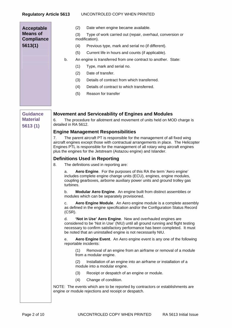
Regulatory Article 5613 UNCONTROLED COPY WHEN PRINTED
Page 2 of 10 UNCONTROLED COPY WHEN PRINTED RA 5613 Initial Issue
Acceptable Means of Compliance
5613(1)
(2) Date when engine became available.
(3) Type of work carried out (repair, overhaul, conversion or modification).
(4) Previous type, mark and serial no (if different).
(5) Current life in hours and counts (if applicable).
b. An engine is transferred from one contract to another. State:
(1) Type, mark and serial no.
(2) Date of transfer.
(3) Details of contract from which transferred.
(4) Details of contract to which transferred.
(5) Reason for transfer
Guidance Material
5613 (1)
Movement and Serviceability of Engines and Modules 6. The procedure for allotment and movement of units held on MOD charge is detailed in RA 5612.
Engine Management Responsibilities 7. The parent aircraft PT is responsible for the management of all fixed wing aircraft engines except those with contractual arrangements in place. The Helicopter Engines PTL is responsible for the management of all rotary wing aircraft engines plus the engines for the Jetstream (Astazou engine) and Islander.
Definitions Used in Reporting 8. The definitions used in reporting are:
a. Aero Engine. For the purposes of this RA the term ‘Aero engine’ includes complete engine change units (ECU), engines, engine modules, coupling gearboxes, airborne auxiliary power units and ground trolley gas turbines.
b. Modular Aero Engine. An engine built from distinct assemblies or modules which can be separately provisioned.
c. Aero Engine Module. An Aero engine module is a complete assembly as defined in the engine specification and/or the Configuration Status Record (CSR).
d. ‘Not in Use’ Aero Engine. New and overhauled engines are considered to be ‘Not in Use’ (NIU) until all ground running and flight testing necessary to confirm satisfactory performance has been completed. It must be noted that an uninstalled engine is not necessarily NIU.
e. Aero Engine Event. An Aero engine event is any one of the following reportable incidents:
(1) Removal of an engine from an airframe or removal of a module from a modular engine.
(2) Installation of an engine into an airframe or installation of a module into a modular engine.
(3) Receipt or despatch of an engine or module.
(4) Change of condition.
NOTE: The events which are to be reported by contractors or establishments are engine or module rejections and receipt or despatch.

UNCONTROLED COPY WHEN PRINTED Regulatory Article 5613
RA 5613 Initial Issue UNCONTROLED COPY WHEN PRINTED Page 3 of 10
Reporting Procedures 9. A reportable ‘Aero Engine Event’ must be reported as soon as practicable. The type of event being reported will determine which Message is used.
Engine Rejection Message The format and instructions for completion of an ERM are detailed in Annex C for those paragraphs which are not applicable contractors must enter N/A. It must be noted that MOD Form 760 is only used with an ERM when investigation is recommended and further details are required.
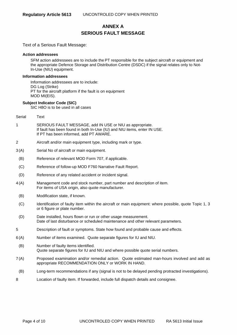
Regulatory Article 5613 UNCONTROLED COPY WHEN PRINTED
Page 4 of 10 UNCONTROLED COPY WHEN PRINTED RA 5613 Initial Issue
ANNEX A
SERIOUS FAULT MESSAGE Text of a Serious Fault Message:
Action addressees
SFM action addressees are to include the PT responsible for the subject aircraft or equipment and the appropriate Defence Storage and Distribution Centre (DSDC) if the signal relates only to Not-In-Use (NIU) equipment.
Information addressees
Information addressees are to include: DG Log (Strike) PT for the aircraft platform if the fault is on equipment MOD MI(EIS).
Subject Indicator Code (SIC) SIC H8O is to be used in all cases
Serial Text
1 SERIOUS FAULT MESSAGE, add IN USE or NIU as appropriate. If fault has been found in both In-Use (IU) and NIU items, enter IN USE. If PT has been informed, add PT AWARE.
2 Aircraft and/or main equipment type, including mark or type.
3 (A) Serial No of aircraft or main equipment.
(B) Reference of relevant MOD Form 707, if applicable.
(C) Reference of follow-up MOD F760 Narrative Fault Report.
(D) Reference of any related accident or incident signal.
4 (A) Management code and stock number, part number and description of item. For items of USA origin, also quote manufacturer.
(B) Modification state, if known.
(C) Identification of faulty item within the aircraft or main equipment: where possible, quote Topic 1, 3or 6 figure or plate number.
(D) Date installed, hours flown or run or other usage measurement. Date of last disturbance or scheduled maintenance and other relevant parameters.
5 Description of fault or symptoms. State how found and probable cause and effects.
6 (A) Number of items examined. Quote separate figures for IU and NIU.
(B) Number of faulty items identified. Quote separate figures for IU and NIU and where possible quote serial numbers.
7 (A) Proposed examination and/or remedial action. Quote estimated man-hours involved and add as appropriate RECOMMENDATION ONLY or WORK IN HAND.
(B) Long-term recommendations if any (signal is not to be delayed pending protracted investigations).
8 Location of faulty item. If forwarded, include full dispatch details and consignee.

UNCONTROLED COPY WHEN PRINTED Regulatory Article 5613
RA 5613 Initial Issue UNCONTROLED COPY WHEN PRINTED Page 5 of 10
ANNEX B CONTENT AND LAYOUT OF A RECEIPT / DESPATCH MESSAGE
The content and layout of a receipt or despatch message is as follows:
ADDRESSEES: Responsible Engine Management PTL (paragraph 7)
TEXT:
A RECEIPT/DESPATCH (as applicable)
B Not applicable
C Engine Type, Mark and Serial No.
D Allotment Number
E Received from/Despatched to (as applicable)
F Date of receipt or despatch
G Details of transportation equipment used and method of movement by which engine was despatched
H Not applicable
J Modification state of received item - (Note 1)(Not applicable to contractor)
K (1) For each engine module the module Type, Mark and Serial No. and whether or not reconditioned (Note 2)
(2)
(3)
NOTE 1 For modular engines, only modifications which affect the overall engine and not individual modules are to be included.
NOTE 2 K is for contractor's use only, and is only to be completed when a modular engine has been despatched. Details of Module MO1 are to be given in K (1), of Module MO2 in K (2) etc.

Regulatory Article 5613 UNCONTROLED COPY WHEN PRINTED
Page 6 of 10 UNCONTROLED COPY WHEN PRINTED RA 5613 Initial Issue
ANNEX C ENGINE REJECTION MESSAGE FORMAT
The following full Message format is given to aid contractor interpretation of Messages received from Service units: Text of aero-engine and accessory rejection Messages: At the beginning of text insert: FOR (Name) PT AND (Contractor) PRODUCT SUPPORT DEPT. Serial Text
A(1). Insert AERO-ENGINE REJECTION or ACCESSORY REJECTION as appropriate. Follow by
type mark of related aero-engine and, if applicable, NIU.
A(2). Insert relevant rejection condition (Note 3)
A(3). Insert reference of MOD Form 707 relating to rejection.
A(4). Is there a related serious fault Message? Delete if inapplicable.
A(5). Insert SIC or DTG of accident or incident Message.
A(6). Insert MOD Form 760 reference if rejection results from a serious fault reported.
B. Insert serial number of rejected aero-engine or type, mark and serial number of rejected accessory.
C. For a modular aero-engine name the modules causing the rejection. For a non-modular aero-engine or accessory name the components or assemblies causing the rejection and insert their flying hours, and counts parameters and counts if applicable, since new or since last reconditioning.
D. Insert type, mark and serial number of aircraft and installed position from which aero-engine or accessory rejected, or insert UNINSTALLED.
E. Insert date of rejection.
F. Insert present location of rejected aero-engine or accessory.
G(1). Insert detailed description of symptoms and circumstances of fault and, if applicable, health monitoring technique used. Include a summary of any related report by aircraft captain or NCO IC ground run (Note 1).
G(2). Was aero-engine shut down prematurely? Insert YES or NO.
G(3). Insert any other relevant information (Note 2).
H. Insert suggested cause of failure when not clear from sub-para A(2) or G(1). (Note 1).
J(1). For a modular aero-engine insert the flying hours attributed to the aero-engine serial number. For a non-modular aero-engine or accessory insert the flying hours since new or since last reconditioning or PLR (Gnome engine only) whichever was completed most recently.
J(2). Insert the flying hours since aero-engine or accessory was last conditioned RC or RD.
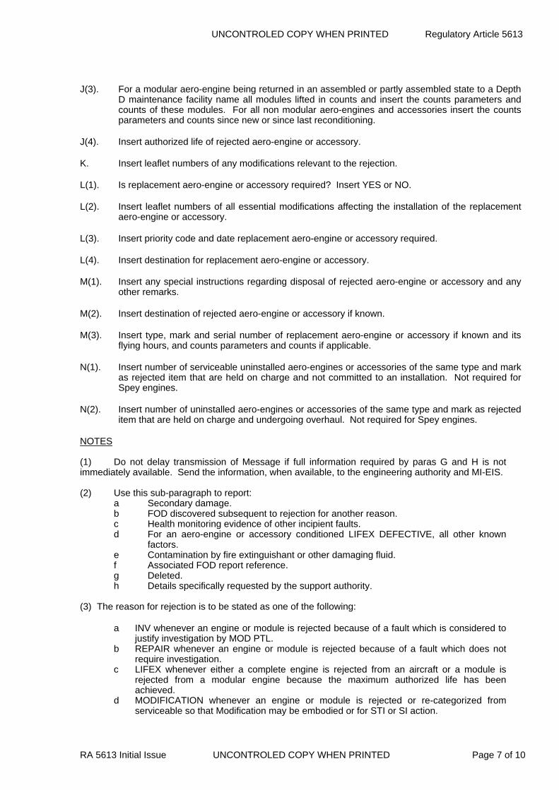
UNCONTROLED COPY WHEN PRINTED Regulatory Article 5613
RA 5613 Initial Issue UNCONTROLED COPY WHEN PRINTED Page 7 of 10
J(3). For a modular aero-engine being returned in an assembled or partly assembled state to a Depth
D maintenance facility name all modules lifted in counts and insert the counts parameters and counts of these modules. For all non modular aero-engines and accessories insert the counts parameters and counts since new or since last reconditioning.
J(4). Insert authorized life of rejected aero-engine or accessory.
K. Insert leaflet numbers of any modifications relevant to the rejection.
L(1). Is replacement aero-engine or accessory required? Insert YES or NO.
L(2). Insert leaflet numbers of all essential modifications affecting the installation of the replacement aero-engine or accessory.
L(3). Insert priority code and date replacement aero-engine or accessory required.
L(4). Insert destination for replacement aero-engine or accessory.
M(1). Insert any special instructions regarding disposal of rejected aero-engine or accessory and any other remarks.
M(2). Insert destination of rejected aero-engine or accessory if known.
M(3). Insert type, mark and serial number of replacement aero-engine or accessory if known and its flying hours, and counts parameters and counts if applicable.
N(1). Insert number of serviceable uninstalled aero-engines or accessories of the same type and mark as rejected item that are held on charge and not committed to an installation. Not required for Spey engines.
N(2). Insert number of uninstalled aero-engines or accessories of the same type and mark as rejected item that are held on charge and undergoing overhaul. Not required for Spey engines.
NOTES (1) Do not delay transmission of Message if full information required by paras G and H is not immediately available. Send the information, when available, to the engineering authority and MI-EIS. (2) Use this sub-paragraph to report:
a Secondary damage. b FOD discovered subsequent to rejection for another reason. c Health monitoring evidence of other incipient faults. d For an aero-engine or accessory conditioned LIFEX DEFECTIVE, all other known factors. e Contamination by fire extinguishant or other damaging fluid. f Associated FOD report reference. g Deleted. h Details specifically requested by the support authority.
(3) The reason for rejection is to be stated as one of the following:
a INV whenever an engine or module is rejected because of a fault which is considered to justify investigation by MOD PTL.
b REPAIR whenever an engine or module is rejected because of a fault which does not require investigation.
c LIFEX whenever either a complete engine is rejected from an aircraft or a module is rejected from a modular engine because the maximum authorized life has been achieved.
d MODIFICATION whenever an engine or module is rejected or re-categorized from serviceable so that Modification may be embodied or for STI or SI action.
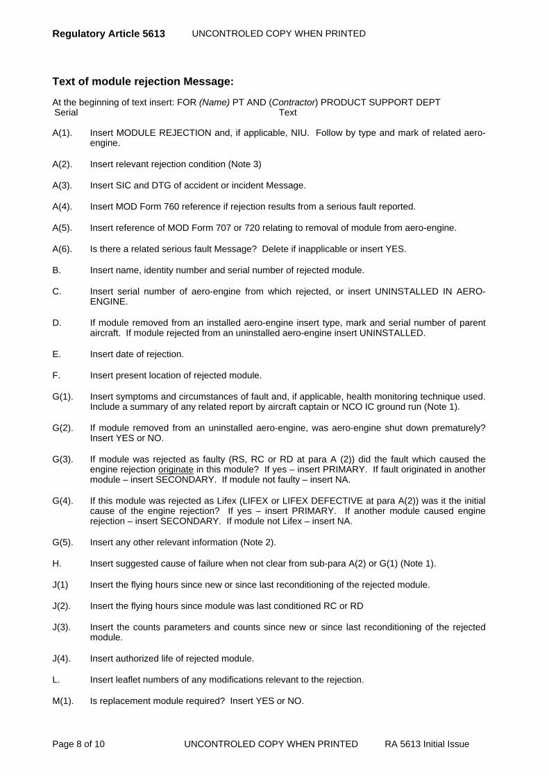
Regulatory Article 5613 UNCONTROLED COPY WHEN PRINTED
Page 8 of 10 UNCONTROLED COPY WHEN PRINTED RA 5613 Initial Issue
Text of module rejection Message: At the beginning of text insert: FOR (Name) PT AND (Contractor) PRODUCT SUPPORT DEPT Serial Text
A(1). Insert MODULE REJECTION and, if applicable, NIU. Follow by type and mark of related aero-
engine.
A(2). Insert relevant rejection condition (Note 3)
A(3). Insert SIC and DTG of accident or incident Message.
A(4). Insert MOD Form 760 reference if rejection results from a serious fault reported.
A(5). Insert reference of MOD Form 707 or 720 relating to removal of module from aero-engine.
A(6). Is there a related serious fault Message? Delete if inapplicable or insert YES.
B. Insert name, identity number and serial number of rejected module.
C. Insert serial number of aero-engine from which rejected, or insert UNINSTALLED IN AERO-ENGINE.
D. If module removed from an installed aero-engine insert type, mark and serial number of parent aircraft. If module rejected from an uninstalled aero-engine insert UNINSTALLED.
E. Insert date of rejection.
F. Insert present location of rejected module.
G(1). Insert symptoms and circumstances of fault and, if applicable, health monitoring technique used. Include a summary of any related report by aircraft captain or NCO IC ground run (Note 1).
G(2). If module removed from an uninstalled aero-engine, was aero-engine shut down prematurely? Insert YES or NO.
G(3). If module was rejected as faulty (RS, RC or RD at para A (2)) did the fault which caused the engine rejection originate in this module? If yes – insert PRIMARY. If fault originated in another module – insert SECONDARY. If module not faulty – insert NA.
G(4). If this module was rejected as Lifex (LIFEX or LIFEX DEFECTIVE at para A(2)) was it the initial cause of the engine rejection? If yes – insert PRIMARY. If another module caused engine rejection – insert SECONDARY. If module not Lifex – insert NA.
G(5). Insert any other relevant information (Note 2).
H. Insert suggested cause of failure when not clear from sub-para A(2) or G(1) (Note 1).
J(1) Insert the flying hours since new or since last reconditioning of the rejected module.
J(2). Insert the flying hours since module was last conditioned RC or RD
J(3). Insert the counts parameters and counts since new or since last reconditioning of the rejected module.
J(4). Insert authorized life of rejected module.
L. Insert leaflet numbers of any modifications relevant to the rejection.
M(1). Is replacement module required? Insert YES or NO.

UNCONTROLED COPY WHEN PRINTED Regulatory Article 5613
RA 5613 Initial Issue UNCONTROLED COPY WHEN PRINTED Page 9 of 10
M(2). Insert leaflet numbers of all essential modifications affecting the installation of the replacement module.
M(3). Insert priority code and date replacement module required.
M(4). Insert destination for replacement module.
N(1). Insert any special instructions regarding disposal of rejected module and any other remarks.
N(2). Insert destination of rejected module if known.
N(3). Insert name, identity number and serial number of replacement module if known, and its flying hours and counts parameters and counts if applicable.
NOTES (1) Do not delay transmission of Message if full information required by paras G and H is not immediately available. Send the information, when available, to the engineering authority and MI-EIS. (2) Use this sub-paragraph to report:
a. FOD discovered subsequent to rejection for another reason. b. Health monitoring evidence of other incipient faults. c. For a module conditioned LIFEX DEFECTIVE, all other known faults. d. Contamination by fire extinguishant or other damaging fluid. e. Associated FOD report reference. f. Deleted g. Details specifically requested by the support authority. h. For NIU modules, state location of last Depth C/D repair or overhaul.
(3) The reason for rejection is to be stated as one of the following:
a. INV whenever an engine or module is rejected because of a fault which is considered to
justify investigation by the PTL b. REPAIR whenever an engine or module is rejected because of a fault which does not
require investigation.
c. LIFEX whenever either a complete engine is rejected from an aircraft or a module is rejected from a modular engine because the maximum authorized life has been achieved.
d. MODIFICATION whenever an engine or module is rejected or re-categorized from serviceable so that the Modification may be embodied or for STI or SI action.

Regulatory Article 5613 UNCONTROLED COPY WHEN PRINTED
Page 10 of 10 UNCONTROLED COPY WHEN PRINTED RA 5613 Initial Issue
Intentionally Blank for Print Pagination
UNCONTROLLED COPY WHEN PRINTED Regulatory Article 5614
RA 5614 Initial Issue UNCONTROLLED COPY WHEN PRINTED Page 1 of 2
RA 5614 - Repair / Salvage Schemes for Engines and Associated Equipment
Rationale This RA details the procedures for the initiation and progression of Repair/Salvage schemes for engines and associated equipment. Such schemes may be raised for the recovery of those used parts which do not satisfy the criteria for re-use. The procedures are applicable to engines and associated equipment for which the engine contractor has PDS responsibilities under a contract from MOD.
Contents 5614(1): Repair / Salvage Schemes for Engines and Associated Equipment
Regulation
5614(1)
Repair / Salvage Schemes for Engines and Associated Equipment 5614(1) All Repair/Salvage schemes shall be submitted for approval
as modifications and shall be listed in the relevant Configuration Status Record (CSR).
Acceptable Means of Compliance
5614(1)
1. Formal procedures for the initiation and progression of Repair/Salvage schemes should be laid down in the contractor's internal procedures.
2. These procedures should provide for audit to ensure conformity with the instruction. Such Repair/Salvage schemes are subject to the controls detailed in this RA and the terms of the applicable contract.
3. It should be demonstrated that the scrap arising from overhaul is subject to periodic review i.e. daily, weekly, with the object of achieving the most cost effective repair when related to Service requirements. The PTL should be invited to attend such reviews in order to give the MOD view on any component repairability in terms of any other factors that may affect a decision.
4. The contractor should ensure that appropriate items are being discarded from Repairs Awaiting Disposal Advice (RADA) store following review, and that RADA stock is kept at a manageable level.
5. Parts for which an approved Repair/Salvage scheme does not exist, but have a potential for repair should be held as RADA and be subject to periodic review.
Guidance Material
5614(1)
Repair / Salvage Schemes for Engines and Associated Equipment
Financial considerations 6. The cost limit, above which restoration to an acceptable standard is deemed to be uneconomical, is defined in Overhaul and Repair of Spares Contracts. The limit is expressed as a percentage of the cost of a new part and it must be noted that the cost of restoration to an acceptable standard includes all repair and any modification work to the part and also the value of any parts required (including Contractors Repair Supply Procedure (CRSP)) to effect the restoration.
7. Before a scheme is prepared, the stock position of the item must be considered in the light of the current forecast of the length of time the item is intended to remain in service.
8. Normally a scheme will not be approved if the estimated cost to the Ministry of Defence i.e. labour and materials (plus profit etc.) plus parts, including the value of parts issued from MOD stocks (but excluding VAT) of applying it is more than a

Regulatory Article 5614 UNCONTROLLED COPY WHEN PRINTED
Page 2 of 2 UNCONTROLLED COPY WHEN PRINTED RA 5614 Initial Issue
Guidance Material
5614(1)
specified percentage (nominally 75%) of the current price of a new part to the MOD.
9. Exceptionally, a scheme; the estimated cost of which exceeds the specified percentage (nominally 75%) of the current price for a new part, may be approved if the supply of a new part is constrained by non-availability of materials, source of supply, manufacturing time etc.
10. It may be that not all applications of a scheme are successful. Abortive work incurred will therefore need to be taken into account in considering the economy of continued application of the repair scheme.
Lifing Considerations 11. In assessing the cost effectiveness of any application of a scheme the aspects in paragraphs 12 and 13 are to be considered.
12. In the case of items having a finite life the residual life after application of the scheme is a measure of the saving. The value of repair is calculated by:
Cost of Repair x Finite Life x 100 = 75% or less Cost of New x Remaining Life
13. Long life parts in older engines may increasingly need to be considered for Repair/Salvage. An engineering assessment of the cumulative cost of maintaining the item at subsequent overhauls may indicate that replacement is the cheaper alternative when new parts are available from stock or can still be manufactured economically. Account is to be taken of the remaining In-Service life of the equipment in relation to the assets held in CRSP.
Application of Schemes Prior to Approval by the Modification Committee 14. Repair/Salvage schemes may be applied prior to approval by the relevant Modification Committee to the extent that such action is authorized in the Overhaul or Repair of Spares Contract.
15. If a Repair/Salvage scheme requires the provisioning of parts and/or tooling this may also proceed in advance of approval, subject to the terms and conditions of the applicable contract and, provided that the following conditions are met:
a. The scheme has been raised in accordance with the formal procedure detailed in the Configuration Management Plan (CMP) and the modification to introduce the scheme into the CSR is in course of preparation for submission to the Local Technical Committee (LTC) / Configuration Control Board (CCB).
b. The ordering of parts and/or tooling is approved by the PTL or his authorized representative. Normally this approval will not be given unless it can be demonstrated that the estimated cost of such parts/tooling will be offset by the savings that will accrue from the application of the scheme to the estimated arisings in the scheduled overhaul programme in one year from the first application of the scheme.
UNCONTROLLED COPY WHEN PRINTED Regulatory Article 5615
RA 5615 Initial Issue UNCONTROLLED COPY WHEN PRINTED Page 1 of 6
RA 5615 - Production Procedures for Engines and Associated Equipment
Rationale This RA details the production procedures that are applicable when new or overhauled engines and associated equipment are procured from an engine contractor on a MOD contract.
Contents 5615(1): Production Release Procedure
5615(2): Quality Verification Tests
Regulation
5615(1)
Production Release Procedure 5615(1) A series of Production Release Meetings shall be convened
to allow and record the progressive release of the whole of the equipment to manufacture resulting in it being taken Under Ministry Control (UMC).
Acceptable Means of Compliance
5615(1)
Production Release Procedure 1. If there is a financial limitation on the contract, the minutes of the Production Release Meetings should carry a certification by the contractor that any irrevocable commitment will not exceed the contracted financial limit.
Concessions 2. The procedure for Concessions should be in accordance with Part 1 of Def Stan 05-61.
Relaxation of Acceptance Testing and Strip Examination 3. If, for a particular contract, either party requires either a relaxation or increase in the extent of testing or dismantling the matter should be referred to the PTL. If the requirement is acceptable to both parties then, subject to negotiation of any appropriate contract schedule changes by the MOD Contracts Branch and the contractor, the contract should be amended to reflect the change in requirements.
4. All ‘Full’ and ‘Relaxed’ acceptance test schedules should record the approval of the PTL and the contractor.
Control of Special to Contract Tools 5. Provision, control and disposal of special to contract tools should be carried out in accordance with DEFCON 23 unless otherwise specified in the contract.
6. The contractor should compile and maintain a tooling register as required by DEFCON 23 or otherwise specified in the contract.
7. Modification tooling is that which is provisioned, or existing tooling which is modified, as a result of the introduction of a modification to an equipment or component part thereof. Tooling in this category should be separately entered in the tooling register as modification tooling and be listed against the modified equipment, showing the appropriate modification number.

Regulatory Article 5615 UNCONTROLLED COPY WHEN PRINTED
Page 2 of 6 UNCONTROLLED COPY WHEN PRINTED RA 5615 Initial Issue
Guidance Material
5615(1)
8. This RA is mainly for information purposes since the procedures will only apply to the extent detailed in the contract. It is not intended that this RA will form a contractual requirement on its own.
Production Release Procedure 9. To meet a required In-Service date the initial stages of production may overlap the later stages of development. It may, therefore, be necessary to place a production contract and to release materials and tooling and to manufacture progressively before development is complete.
10. Under the terms of the production contract the manufacturing contractor may be required to:
a. Bear all such risk himself.
b. Receive payment for such expenditure.
c. Share some or all of the risk with MOD.
Production Release Meetings 11. Where paragraphs 11.b) or 11.c) apply the PTL or contractor will convene a series of Production Release Meetings, the minutes of which will provide a record of the phased release to manufacture and the progressive authorization of expenditure and commitment to expenditure. The purpose of Production Release Meetings is to:
a. Assess the risk of releasing design schemes of an engine or accessory which incorporate specified design features to production in advance of development validation.
b. Advise and assist the PTL to reach a decision on any release to production within the terms of the relevant contract.
c. Identify the development and production milestones that will be achieved for production release to occur.
Categories of Release to Manufacture 12. Restricted release may be required where there are design features of a part which are at risk pending validation. Such restricted release will be allocated a category appropriate to the method of manufacture and procurement time. The release categories are as follows:
a. Category 1 - Basic Materials: Long dated strategic materials such as bars, billets, sheets and slabs etc. There must be no expenditure on tooling, neither must there be any irrevocable commitment of standard engineering materials capable of reclamation or utilization elsewhere, and for which there is a concurrent requirement.
b. Category 2 - Formed Materials: When development has progressed further and design begins to stabilise, basic materials may be worked on to produce forgings and castings etc. Dies and moulds etc. will be required for this category and this type of tooling is designated as Category ‘A’. Lead times may require Category ‘A’ tooling release before Category ‘2’ release of material.
c. Category 3 - Full Manufacture: Tooling such as machining and fabrication jigs and fixtures, inspection gauges etc. will be required for this category. This tooling is designated as Category ‘B’ and lead times may require Category ‘B’ tooling release before Category ‘3’ release of parts.
Category Updating and Cost Control 13. Category ‘1’ release will not require either updating or cost control. For Category ‘2’ release there is a requirement for control of material and tooling costs since the design will still be fluid. Changes to Category ‘3’ will require the approval of the PTL if the materiel is UMC.

UNCONTROLLED COPY WHEN PRINTED Regulatory Article 5615
RA 5615 Initial Issue UNCONTROLLED COPY WHEN PRINTED Page 3 of 6
Guidance Material
5615(1)
Progression of Deliveries 14. The PTL is responsible for the overall management of programmes of work on, and deliveries of, engines and associated equipment. These responsibilities include:
a. Monitoring deliveries in accordance with programmes defined in contracts.
b. Progressing of deliveries.
c. Other specific progressing activities such as arrangement of spares progress meetings.
15. Where the responsibility for an engine or associated equipment rests with an PTL he will retain responsibility for:
a. Complete new engines for initial fit.
b. Overhaul, conversion or retrospective modification programmes at a contractor's works including new equipment purchased in aid thereof.
c. New build engines for use as reserves.
16. In order to meet their progressing responsibilities the MOD will require an adequate flow of information to be provided by the contractor. Existing reporting systems will be used as far as practicable but where changes are considered necessary the PTL will consider, in conjunction with the contractor, how best to develop a mutually satisfactory system.
Contractual Authority 17. Any progressing or related action carried out by the PTL or his representatives is without prejudice to the rights of the parties to the relevant contracts. Except as may be specifically provided for in the contract documents, authority to commit MOD by contract is vested solely in the contracts branch concerned.
Overhaul Requirement Meetings and Repair Arising Meetings 18. For overhaul of engines and associated equipment the required monthly output figures are agreed at Overhaul Requirement Meetings (ORMs) for engine contractors and at Repair Arising Meetings (RAMs) for engine accessory contractors.
19. ORMs and RAMs will be convened as often as required but normally twice a year will be appropriate for a major contractor and once per year for contractors with smaller programmes. The purpose of ORMs and RAMs is to:
a. State the MOD requirement for monthly output of overhauled equipment during the succeeding 12 months.
b. Reach agreement on a compromise programme if the output offered by the contractor does not meet the MOD requirement.
c. Ensure that the contractor's holdings and anticipated inputs of equipment are adequate to meet the agreed programme.
d. Review the contractor's output performance.
e. Provide the contractor with the forecast MOD requirements.
f. Provide a forum for the discussion and resolution of mutual problems affecting the overhaul activity.
20. The membership and responsibilities for the ORM and RAM meetings are as follows:
a. The PTL will Chair the meeting.
b. A PT Quality representative may be invited to attend to provide advice as required.
c. The Contractor will convene the meeting and record the minutes.
Regulatory Article 5615 UNCONTROLLED COPY WHEN PRINTED
Page 4 of 6 UNCONTROLLED COPY WHEN PRINTED RA 5615 Initial Issue
Guidance Material
5615(1)
d. The contractor is to provide representation, at a senior level, of personnel responsible for the following functions:
(1) Overhaul shop management.
(2) Production control.
(3) Other specialists such as Spares Controller, Product Support Quality Assurance or Commercial Dept as required.
Monitoring of Contractor Achievement 21. Monitoring of achievement and progress by the contractor may be implemented by one or more of the following methods, or other systems as defined in the contract that will provide equivalent data:
a. Monthly returns to the PTL for new production and for overhaul showing input and output.
b. Regular meetings convened to establish the position of all new production or overhauls being undertaken. These meetings may be convened by the PTL and used to establish shortfalls likely to affect achievement of the ORM targets so that appropriate action can be taken by the PTL or contractor to recover the situation.
c. Regular input, output and status information provided by the contractor in a form acceptable to the PTL.
Provisioning of Spares 22. Spares provisioning for engines and associated equipment is to be carried out in accordance with the requirements of 5400 series RAs as appropriate. Where the use of the International Specification for Materiel Management is stipulated in the contract reference is to be made to 5400 series RAs.
Relaxation of Acceptance Testing and Strip Examination 23. Specifications for engines and accessories and rotorcraft gearboxes and Def Stan 00-970 Pt. 11 prescribe a ‘full’ acceptance test sequence comprising an endurance test, strip examination and final test or a ‘relaxed’ acceptance test comprising a combined endurance and final test without strip examination. (These are sometimes referred to as ‘Non-Eased’ and ‘Eased’ tests.)
24. Experience has shown that relaxation of testing and stripping can be applied without detriment to the quality of manufacture or overhaul, or to the behaviour of the equipment in service. The relevant contract will stipulate the number of engines or units which are to be subject to a ‘full’ acceptance test, and the extent of dismantling for examination. All other items will be subjected to a ‘relaxed’ acceptance test.
Control of Special to Contract Tools 25. Special to contract tools are defined as those such as jigs, fixtures, NC tapes, computer programs and data, moulds, dies and unique manufacturing gauges which are essential for production or overhaul. It does not include standard tools of the trade that the contractor would provide.
Regulation
5615(2)
Quality Verification Tests 5615(2) The contractor shall ensure that, when conducting Quality
Verification Tests (QVT), the test, strip examination and preparation and issue of the report proceed as quickly as possible so that the results and confirmation of the standard of quality become available with the minimum of delay, unless otherwise agreed by the PTL.

UNCONTROLLED COPY WHEN PRINTED Regulatory Article 5615
RA 5615 Initial Issue UNCONTROLLED COPY WHEN PRINTED Page 5 of 6
Acceptable Means of Compliance
5615(2)
26. A unit selected for QVT should have completed its production acceptance tests and should be tested in accordance with the approved QVT schedule. Any variation should be agreed by the PTL and the contractor.
27. The contractor should ensure that the test is completed and the QVT report should be issued within 2 months of unit selection.
Guidance Material
5615(2)
28. Quality Verification Testing (QVT) is an essential quality assurance procedure that is applied to new and overhauled engines and associated equipment to provide confidence that they are produced or overhauled to the required standard.
Applicability 29. The frequency together with the applicable QVT schedule and extent of strip examination will be specified in the relevant contract. Circumstances to be considered for QVT implementation include the following:
a. On initial production of engines and associated equipment.
b. On a change of contractor or after significant changes at a contractor's works, such as methods of production or manufacturing source.
c. After a significant break in production or overhaul.
d. At commencement of a major overhaul, rework, conversion or update programme.
e. After major design change.
f. After detection of significant defects at the contractor's works or in service.
30. A breakdown of the unit on test, failure to reach the specified performance or the discovery of a major defect on strip examination is to be reported promptly.
31. Immediately following the specified strip and inspection, a report on the results of the QVT will be compiled by the contractor. The report, certified by the contractor's Quality Manager/Chief Inspector, will be circulated to the PTL within 4 weeks of the strip examination being completed.

Regulatory Article 5615 UNCONTROLLED COPY WHEN PRINTED
Page 6 of 6 UNCONTROLLED COPY WHEN PRINTED RA 5615 Initial Issue
Intentionally Blank for Print Pagination
UNCONTROLLED COPY WHEN PRINTED Regulatory Article 5616
RA 5616 Initial Issue UNCONTROLLED COPY WHEN PRINTED Page 1 of 2
RA 5616 - Drawing Procedure, Control of Designs and Design Records
Rationale This RA details the procedures to be used for drawings, the control of designs and design records originating from MOD contracts.
Contents 5616(1): Drawing Procedure, Control of Designs and Design Records
Regulation
5616(1)
Drawing Procedure, Control of Designs and Design Records 5616(1) All drawings originating under MOD contracts shall conform
to Def Stan 05-10 unless otherwise stated in the contract.
Acceptable Means of Compliance
5616(1)
Drawing Procedure, Control of Designs and Design Records 1. Where a contractor intends to reproduce drawings on a computer with no facility for the production of eye-legible hard copy, a data exchange format and physical exchange media standard should be agreed with the PTL prior to commencement of design work.
Requirements additional to those of Def Stan 05-10 2. Life Marking: The location and method of life marking for critical and other specified parts should be identified in accordance with Def Stan 00-970 Pt 11.
Security marking of drawings 3. The PTL should notify the contractor of the security classification of a project or equipment which should be required to be applied to appropriate drawings. No work should be started by the contractor until this information is received.
4. Where a contractor intends to use a computer system to produce, store or modify drawings which would, either individually or collectively, be classified CONFIDENTIAL or above, prior clearance should be obtained from the PTL.
5. A complete or substantially complete set of drawings, prints, aperture cards or computer records should bear the classification applicable to the project or equipment. Individual drawings, however, may carry a lower classification according to content.
6. When finalised all classified drawings, associated prints and aperture cards should have the appropriate security grading stamped on them in bold letters before they are issued.
7. Eye-legible output from a computer held drawing (e.g. screen display or hard copy) should bear the security classification of the drawing in a prominent place. In addition any portable data storage medium, such as computer discs or tapes, which hold or have held such records should be clearly marked with the appropriate security classification and stored accordingly.
8. Control of designs and design records should meet the requirements and procedures of RA 5301 and RA 5302.

Regulatory Article 5616 UNCONTROLLED COPY WHEN PRINTED
Page 2 of 2 UNCONTROLLED COPY WHEN PRINTED RA 5616 Initial Issue
Guidance Material
5616(1)
Drawing Procedure, Control of Designs and Design Records 9. Drawings may consist of traditional drawings or computer records containing equivalent information.
Control of designs and design records 10. Where a Drawing Instruction Sheet (DIS) has previously been produced under Def Stan 05-124 (now Obsolescent), this may form a significant part of the Configuration Status Record (CSR), however a configuration management plan is required unless otherwise agreed in the contract.

UNCONTROLLED COPY WHEN PRINTED Regulatory Article 5617
RA 5617 Initial Issue UNCONTROLLED COPY WHEN PRINTED Page 1 of 10
RA 5617 - Post Delivery Fault Reporting and Investigation
Rationale This RA states the standard procedures to be used by contractors for post delivery fault reporting and investigation. This includes the reporting of faults that may be present in government owned materiel held at contractor's works and the investigation of faults reported by the Services, MOD establishments and contractors.
Contents 5617(1): Post Delivery Fault Reporting and Investigation
Regulation
5617(1)
Post Delivery Fault Reporting and Investigation 5617(1) Faults present in government owned materiel held at
contractor's works and the investigation of faults reported by the Services, MOD establishments and contractors shall be reported using the procedures in this RA.
Acceptable Means of Compliance
5617(1)
Post Delivery Fault Reporting and Investigation 1. The identification of a particular report as Not in Use (NIU) or In Use (IU) should be without prejudice to any contractual liability.
Reporting by Contractors 2. Government furnished assets (GFA) supplied to a contractor and found to be faulty whilst at a contractors works, should be reported in accordance with RA 5404. However, this requirement should not apply to materiel issued to a contractor for overhaul, including component parts thereof, unless a fault is revealed in the course of overhaul which in the opinion of the contractor is sufficiently serious to warrant fault investigation.
Investigation Reporting 3. On completion of an investigation, the investigating contractor should raise MOD Form 761A for engines and modules and MOD Form 761 for components and accessories.
4. MOD Form 761 should be completed in accordance with RA 5404 and returned to the tasking PT focal point.
5. MOD Form 761A should be completed and distributed in accordance with Annex A.
6. Regarding contractual cover; before commencing an authorized investigation, the contractor should ensure that he is in possession of a current contract for such investigations, and that the investigation work will be within the limit of liability of that contract. If this is not so, the PTL should be informed.
7. Regarding remedial action; it is essential that the MOD F761/761A identifies clearly the root cause and the proposed remedial action. The issue of the form should not be delayed pending issue of STI/SI, or agreement to modification proposals. The PTL should be satisfied that:
a. The presence or otherwise of the reported fault is confirmed.
b. Serious faults which can be the consequence of design, manufacture or quality assurance are reported to the relevant PTL.
c. The root cause of the fault is established wherever possible.
d. Appropriate remedial action on all affected materiel whether in use or in

Regulatory Article 5617 UNCONTROLLED COPY WHEN PRINTED
Page 2 of 10 UNCONTROLLED COPY WHEN PRINTED RA 5617 Initial Issue
Acceptable Means of Compliance
5617(1)
store is initiated.
e. Where appropriate, measures are initiated to prevent a recurrence of the fault.
Equipment / System Faults 8. When an investigation at an equipment contractor reveals that the basic cause of a fault may be a system deficiency the PTL should be consulted and if necessary the action transferred. The MOD F761/761A should include the findings of the equipment and system investigation.
Boards of Inquiry 9. When the instruction to investigate states that a board of inquiry is involved, investigation and reporting should conform to the procedures in this RA, (including normal authorisation and contract cover requirements) with the exceptions listed in paragraphs 10 and 11.
10. Regarding release of information; details of an investigation report should not be released prior to the formal distribution of the MOD F761/761A, without the agreement of the Board of Inquiry.
11. Regarding action prior to distribution of MOD F761/761A; after MOD certification of the MOD F761/F761A the following action should be taken:
a. Service Boards of Inquiry: The Board of Inquiry, appropriate Service EA and the PTL are to see the fault investigation report (MOD F761/761A) before distribution.
b. MOD Boards of Inquiry: The Board of Inquiry and appropriate PTL are to see the fault investigation report before distribution.
Cancellation of Authorized Investigations 12. Cancellation of an investigation due to non receipt of the item or for any other reason should be notified to the investigating authority and the appropriate PTL in writing, giving the reason.

UNCONTROLLED COPY WHEN PRINTED Regulatory Article 5617
RA 5617 Initial Issue UNCONTROLLED COPY WHEN PRINTED Page 3 of 10
Guidance Material
5617(1)
Post Delivery Fault Reporting and Investigation 13. Variations from this section may be required for particular projects and to cover development or trials, and will be stated in the contract. Faults on aircraft engines and modules are reported by Engine Rejection Message (ERM) or Module Rejection Message (MRM) as appropriate. Faults on engine components and accessories, propellers and APUs are reported by Form 760. It is Service policy to identify materiel as ‘Not-in-Use’ (NIU), or ‘In-Use’ (IU).
Routing and Authorization of Investigation Requests 14. The investigation of Engine Reject Messages (ERM), and Module Reject Messages (MRM) is requested when the rejection condition in the Message is marked “INV”.
15. Services requesting the investigation of a fault reported on MOD Form 760 forward a MOD Form 760A with Field 1 completed.
16. Faults reported on F760s are actioned in accordance with RA 5404.
Numbering of Authorizations 17. Each engine or equipment type, or in some cases contractor, will have a unique reference prefix agreed by the focal point, e.g.:
a. GN – Gnome.
b. CAN - Avon in Canberra.
c. DRG - Dowty Rotol propellers and gearboxes.
18. Investigations will be allocated serial numbers commencing on 1 April each year. (Other dates may be used if considered more appropriate by the investigation authority.)
19. ‘NIU’ Investigations will be allocated serial numbers in the range 1 - 100, ‘IU’ investigations will be allocated serial numbers in the range 101 onwards.
20. The complete authorization number will consist of prefix/serial number/month/year, e.g.:
a. GN/3/7/86 - Refers to a NIU investigation.
b. CAN/107/9/86 - Refers to an IU investigation.
21. The investigation authority will allocate a separate serial number, sequentially, for each investigation authorized.
22. An example MOD Form 761A is included at Annex B.

Regulatory Article 5617 UNCONTROLLED COPY WHEN PRINTED
Page 4 of 10 UNCONTROLLED COPY WHEN PRINTED RA 5617 Initial Issue
ANNEX A COMPLETION AND DISTRIBUTION OF FORM F761A
A.1 Heading
Delete Overhaul or Investigation and Engine or Module, as necessary.
A.2 Contractor's reference
For contractor's use only - completion is optional.
A.3 Report No
For contractor's use only - Completion is not essential on an overhaul.
A.4 Contract No
Enter contract number(s).
A.5 Contractor Order No
For contractor's use only.
A.6 MOD Ref. No
Contractor to enter when applicable. Completion is not essential on an overhaul.
A.7 Engine Rejection Message SIC
Insert SIC on the Engine Rejection Message.
A.8 Investigation/Overhaul Base
Insert name and location of overhaul base. (Do not use code.)
A.9 Category
Delete as necessary to leave one or more categories applicable to the specific report.
A.10 Pre Strip Test
Delete as necessary. Completion is not essential on an overhaul.
A.11 Associated Reports Reference
Enter the reference of any investigation or other relevant reports.
A.12 Modifier: EIC Code
Shaded area for MOD uses only.
A.13 Ship/Station/Unit/Operator
Copy this from Engine Rejection Message, MOD Form 731 (label) or MOD Form 760, and enter the full name on the ‘dotted line’ below the word operator. Do not use code for the entry.

UNCONTROLLED COPY WHEN PRINTED Regulatory Article 5617
RA 5617 Initial Issue UNCONTROLLED COPY WHEN PRINTED Page 5 of 10
A.14 Originator's Ref. No
Copy this from Engine Rejection Message, MOD Form 731 (Label) or MOD Form 760, in the clear boxes provided, but if the number is not available from any of these sources leave boxes BLANK.
A.15 Engine serial No
Enter the Manufacturer's Serial No in the boxes provided commencing from the left-hand side.
A.16 Aircraft Type and Mark
Copy this from Engine Rejection Message, MOD Form 731 (label) or MOD Form 760; enter in the clear space.
A.17 Event No and Date
For Contractor's use only. Completion is optional.
A.18 Engine Type and Mark
Complete as appropriate.
A.19 Module serial No
Enter the Manufacturer's Serial No in the boxes provided commencing from the left-hand side.
A.20 Module Description
Enter as appropriate.
A.21 Engine/Module Use Since Last Shop Visit
Entry is to be to the nearest hour in the top row of boxes and/or ‘Units’ expended in the second row and enter the date of last shop visit on the third line.
A.22 Engine/Module Use Since Recondition or Overhaul
Entry is to be to the nearest hour in top row of boxes and/or ‘Units’ expended in the second row and enter the date of recondition on the third line.
A.23 Engine/Module Total Use
When known the entry is to be to the nearest hour in the top row of boxes and/or ‘Units’ expended in the second row, otherwise leave the boxes blank.
A.24 Engine/Module Time Supersonic
Enter if recorded.
A.25 Date Engine/Module Received in Shop
Enter date of commencement of investigation or overhaul.
A.26 Primary Defective Part Description Part No Serial No
A.26.1 When a Part is primarily responsible for the failure or return of the Engine/Module being reported, enter its description together with its Part No and Serial No.

Regulatory Article 5617 UNCONTROLLED COPY WHEN PRINTED
Page 6 of 10 UNCONTROLLED COPY WHEN PRINTED RA 5617 Initial Issue
A.26.2 If the reason for Engine/Module rejection is NON-BASIC, all 3 spaces may be left blank.
A.26.3 If a primary faulty part is quoted on an investigation and subsequently that decision is altered significantly due to either further investigation or overhaul findings, a further Form 761A must be completed showing the correct information. It is important that the re-issued Form 761A must refer to any previous report issued and must be clearly stamped ‘RE-ISSUE’.
A.27 Reason for removal
If an Engine/Modules failure, enter a brief description of failure. If not an Engine/Module failure, state reason for return.
A.28 Condition on Strip and Remarks
This section is to be completed for investigation and/or overhaul and must contain a concise description of those parts whose condition is not commensurate with the hours run where this can be reasonably assessed. If FOD is present the cause must be identified wherever possible together with the extent and severity of the damage in general terms.
A.29 Lifex/Basic/Non-Basic
Delete as appropriate.
A.29.1 Lifex An Engine/Module that has reached the life authorized.
A.29.2 Basic (Chargeable to a System or Unit): When a fault failure or damage has occurred as a result of malfunctioning of a system, unit or part (for which design responsibility lies with the Engine Manufacture), while being used in the manner for which it was designed. The word 'Chargeable' in this and the next definition is used in a technical sense only and has no financial implications. A.29.3 Non-Basic Cause (Non-Chargeable to a System or Unit): When a fault, failure or damage has occurred as a result of malfunctioning of a system unit or part:
a) For which the design responsibility does not lie with the Engine Manufacturer.
b) Due to being operated or maintained in a manner for which it was not designed.
c) When manufactured or built contrary to the design specification.
d) When the cause was external.
A.30 Abstract
This part of the report is held on computer records and must highlight the information considered pertinent by the Engineer making the report. It must be completed in block capitals (printed or typed) one character to each space with one space between each word. Punctuation is a character and must occupy its own space. The symbol * must NOT be used. Recognised engineering abbreviations may be used and a word may be continued from one line to another. The Reporting Engineer must underline on the horizontal lines the important words in the Abstract. Care must be taken in the choice of these words as they are used as KEY WORDS at MOD Management Information – Engineering Information Services (MI-EIS) for data retrieval purposes.
A.31 Engine/Module on Investigation
It must contain as a first sentence a statement indicating the precise cause of failure and the prime faulty part. The remainder must contain a summary of the condition of any other components related to the failure. Any reference to health monitoring is to be included and the Engine/Module health report number shown in the ‘Associated Reports Reference’ block. If FOD is present, the cause must be identified whenever possible together with the extent and severity of the damage using general terms

UNCONTROLLED COPY WHEN PRINTED Regulatory Article 5617
RA 5617 Initial Issue UNCONTROLLED COPY WHEN PRINTED Page 7 of 10
in the Abstract. If a defect is not confirmed and it is not considered necessary to strip and overhaul the Engine/Module this must be stated in the Abstract.
A.32 Engine/Module on Overhaul following Investigation
Reference is made to the investigation report and its number in the first sentence. The remainder contains a summary of the condition on strip and any other relevant information. Any reference to health monitoring is included and the Engine/Module health report number shown in the ‘Associated Reports Reference’ block. If FOD is present the cause must be identified whenever possible together with the extent and severity of the damage using general terms in the Abstract.
A.33 Engine/Module on Overhaul (including Lifex engines)
Contains a summary of the condition on strip and any other relevant information. Any reference to health monitoring is included and the Engine/Module health report number shown in the ‘Associated Reports Reference’ block. If FOD is present the cause must be identified whenever possible together with the extent and severity of the damage using general terms in the Abstract.
A.34 Engineer's Ref No Signature and Date
Is completed by the Engineer making the Report.
A.35 Reverse of Form 761A
The reverse of Form 761A is for ‘Investigation only’. A.35.1 Proposed Remedial Action
Is completed by the service Investigation Officer or the Contractor's Engineer.
A.35.2 Liability Statement (where required)
Is completed on investigation only by the contractor before the Form is issued.
A.35.3 Contractor/Investigating Agency Signature Blocks
Contractor/Investigating Agency are to sign, date and add remarks as required.
A.35.4 MOD Approval Blocks
Is completed by the Investigating Authority representative.
A.35.5 Cause of Faults
The Cause of Fault on Investigation is entered in accordance with the Cause of Fault code shown on MOD Form 761.
A.35.6 Service Engineering Authority Comment
Is completed by the PTL when the form is received. It is not necessary for this section to be completed before distribution by the contractor.
A.36 Distribution
After certification by MOD in Field 14, copies are distributed as follows:

Regulatory Article 5617 UNCONTROLLED COPY WHEN PRINTED
Page 8 of 10 UNCONTROLLED COPY WHEN PRINTED RA 5617 Initial Issue
A.36.1 All MOD Requests
a) original to relevant MOD PT EA who after completing Field 15, Service Engineering Authority - Acceptance/Rejection and Proposed Remedial Action, will return a copy to the MOD officer authorizing the investigation;
b) Certifying MOD officers. (As in Field 14);
c) Other MOD PT EAs if materiel is common to more than one application;
d) Reporting MOD Establishment or contractor, if appropriate;
e) Appropriate MOD PT Commercial manager when liability is in question, or when the investigation is related to a Board of Inquiry.
A.36.2 All other requests
a) original to EIS;
b) Certifying MOD officers. (As in Field 14);
c) EAs for the type of material;
d) Reporting MOD contracts branch when liability is in question, or when the investigation is related to a board of inquiry.
NOTE 1 If an amendment to the MOD Form 761A is raised the word ‘amended’ must be written in red at the top of the form. NOTE 2 Where a service repair organisation is involved one copy is sent to the appropriate engine contractor's service manager.
NOTE 3 Where an investigation report includes photographs, an additional 2 copies of the photographs must be forwarded to the EA/DEA.
NOTE 4 The above are minimum requirements and additional copies may be otherwise agreed.
NOTE 5 This distribution also applies to F761As raised by the Overhaul Agency as required by Def Stan 28-8

UNCONTROLLED COPY WHEN PRINTED Regulatory Article 5617
RA 5617 Initial Issue UNCONTROLLED COPY WHEN PRINTED Page 9 of 10
ANNEX B
OVERHAUL/INVESTIGATION REPORT (ENGINE/MODULE) – MOD FORM 761A

Regulatory Article 5617 UNCONTROLLED COPY WHEN PRINTED
Page 10 of 10 UNCONTROLLED COPY WHEN PRINTED RA 5617 Initial Issue

UNCONTROLLED COPY WHEN PRINTED Regulatory Article 5720
RA 5720 Issue 3 UNCONTROLLED COPY WHEN PRINTED Page 1 of 14
►This RA has been substantially re-written; for clarity no change marks are presented – please read RA in entirety◄
RA 5720 - Structural Integrity Management
Rationale The aim of Structural Integrity Management is to counter the threats to Structural Integrity throughout the life of the aircraft or system, across organisational, process and responsibility boundaries, ensuring risks to airworthiness are Tolerable and As Low As Reasonably Practicable (ALARP). Structural Integrity Management requires a planned programme of measures.
Contents 5720(1): Structural Integrity Management
5720(2): Establishing Structural Integrity
5720(3): Sustaining Structural Integrity
5720(4): Validating Structural Integrity
5720(5): Recovering Structural Integrity
5720(6): Exploiting Structural Integrity
Regulation
5720(1)
Structural Integrity Management 5720(1) The Type Airworthiness Authority (TAA) shall be responsible
for Structural Integrity Management, for all aircraft types within their area of responsibility, to ensure an acceptable and demonstrable level of Structural Integrity.
Acceptable Means of Compliance
5720(1)
Structural Integrity Management 1. RA 5720 should be applicable to all new and legacy aircraft types, regardless of procurement model.
2. Where threats to Structural Integrity are identified, related risks should be managed in accordance with RA 1220(2)1 and continually reviewed in response to in-service developments and experience.
3. The Establish-Sustain-Validate-Recover-Exploit (ESVRE) management framework should be used to counter threats to Structural Integrity throughout an aircraft’s life cycle.
4. Personnel with responsibility for Structural Integrity or holding a structures Letter of Airworthiness Authority (LoAA) should attend the Aircraft Structural Integrity Course.
Guidance Material
5720(1)
Structural Integrity Management 5. It is recommended that reference is made to the Structural Integrity Handbook2 for detailed information on all aspects of Structural Integrity.
6. Structural Integrity may be compromised by one, or a combination, of the following threats:
a. Overload.
b. Fatigue, fretting and wear.
1 Refer to RA 1220(2) Project Team Airworthiness and Safety 2 Structural Integrity Handbook (available on the MAA website)

Regulatory Article 5720 UNCONTROLLED COPY WHEN PRINTED
Page 2 of 14 UNCONTROLLED COPY WHEN PRINTED RA 5720 Issue 3
Guidance Material
5720(1)
c. Accidental Damage (AD) and Environmental Damage (ED).
d. Procedural (Design, Manufacturing, Maintenance or Supply) error.
7. It is essential that airworthiness risks arising from Structural Integrity concerns are captured, assessed and managed, in order to assure and preserve the assumptions contained within the Air System Safety Case.
8. Cooperation between the TAA and the Duty Holder (DH) is necessary to ensure overall risk is at least tolerable and ALARP.
9. Stakeholders may contact MAA Cert Structures for advice on this regulation.
Regulation
5720(2)
Establishing Structural Integrity 5720(2) The TAA shall ensure that Structural Integrity is established
to demonstrate that the aircraft structure is airworthy to operate under the Release to Service (RTS) and the assumptions in the Statement of Operating Intent (SOI)/Statement of Operating Intent and Usage (SOIU).
Acceptable Means of Compliance
5720(2)
Establishing Structural Integrity 10. The intended approach for establishing Structural Integrity and managing it through life, for each aircraft type, should be communicated within a Structural Integrity Strategy Document (SISD).
11. An initial SISD, accounting for all anticipated activities under the ESVRE framework, should be issued, and embedded within the Through Life Management Plan (TLMP), before Main Gate on a programme.
12. A Structural Integrity Plan should be produced and referenced within the SISD.
13. Structural Integrity Management should be implemented, documented, and reviewed biannually through the Structural Integrity Working Group (SIWG), and top risks reported to the appropriate Airworthiness Management Group.
14. The SIWG should be chaired by the TAA or the holder of a delegated LoAA that refers specifically to the role of SIWG chair, who is of at least OF4/B2 rank/grade.
15. The SIWG should comprise key structures specialist stakeholders (defined in Table 1) including an appointed Independent Structural Airworthiness Advisor (ISAA).
16. Both the SISD and Structural Integrity Plan should be ratified at each SIWG.
17. Appropriate static strength, fatigue strength and loads validation evidence, obtained during design, substantiation and certification of the aircraft, should be available to support the establishing of Structural Integrity and identified in the SISD.
18. The need to capture data early in service to support the validation of loads and usage assumptions should be considered in advance, during the development phase.
19. An SOI for all new types and significant marks, and SOIU for in-service aircraft, should be developed in consultation with, and formally conveyed to, the Design Organisation (DO).
20. A Structural Examination Programme (SEP), which is called up in an RA 53203-compliant Maintenance Schedule, should be established prior to the In-Service Date (ISD), comprising:
a. Classification of significant structure (see paragraph 21) as either At Risk (AR) or Not at Risk (NAR) from AD or ED.
b. Scheduled examinations based on this classification, and examination and retirement of components according to their fatigue clearances.
c. Sampling of components not normally inspected during scheduled examinations (the Structural Sampling Programme (SSP)).
3 Refer to RA 5320 Aircraft Maintenance Programme – Design Guidelines

UNCONTROLLED COPY WHEN PRINTED Regulatory Article 5720
RA 5720 Issue 3 UNCONTROLLED COPY WHEN PRINTED Page 3 of 14
Acceptable Means of Compliance
5720(2)
21. The Maintenance Schedule should be cross-referenced to a complete list of items conforming to the definition of Structural Significant Items (SSIs) found in MAA024, that is compiled and updated in consultation with the DO.
22. Thresholds for acceptable capture rates of usage data should be defined, so that retirement and inspection of components can be scheduled with adequate confidence.
23. An Environmental Damage Prevention and Control (EDPC) programme including measures to manage the risk to Structural Airworthiness arising from ED should be established in cooperation with the DO5.
Guidance Material
5720(2)
Establishing Structural Integrity Structural Integrity Strategy Document
24. The aim of the SISD is to articulate to key stakeholders how the required Structural Integrity measures for an aircraft will be implemented, in terms of methodology, timescale and financial commitment. It is owned by the TAA. The SISD also forms part of the aircraft’s Safety Assessment and TLMP and, though initiated early in the acquisition cycle, is a living document. It is recommended that reference is made to the MAA SISD template and associated guidance6.
Structural Integrity Plan
25. The Structural Integrity Plan is referenced or integrated within the SISD and is used for routine management and recording of all significant platform Structural Integrity events, ideally organised using the ESVRE framework. It is made available to all Structural Integrity stakeholders.
Structural Integrity Working Group
26. The SIWG discusses Structural Integrity issues and formally endorses Structural Integrity Management processes, decisions and documentation, taking into account projected usage and known risks.
27. Supplementary specialist working groups may support the SIWG as required.
Table 1. SIWG Stakeholders.
Key Stakeholders Other Stakeholders TAA or LoAA holder 1710NAS Material Integrity Group for
specialist scientific and engineering advice. 1710NAS Repair for rotary wing repair information and advice
DO 71(IR) Sqn – for fixed wing repair and NDT issues
PT member responsible for Structural Integrity
MAA Cert S&ADS
Service provider (if applicable) Front Line Command role office ISAA Release to Service Authority (RTSA) Continuing Airworthiness Management Organisation (CAMO)
Stn/Ship/Unit engineering and aircrew
Civil Aviation Authority (for Military Registered Civil Owned Aircraft)
Other regulatory authorities for the same type
PT Safety Manager Requirements Manager Multi-national programme office Original Equipment Manufacturer Commodity PTs DE&S Airworthiness Team (DAT) DH representative
4 Refer to MAA02 MAA Master Glossary 5 Refer to RA 4507 Aircraft Environmental Damage Prevention and Control 6 Structural Integrity Strategy Document Template, available on the MAA website

Regulatory Article 5720 UNCONTROLLED COPY WHEN PRINTED
Page 4 of 14 UNCONTROLLED COPY WHEN PRINTED RA 5720 Issue 3
Guidance Material
5720(2)
28. The ISAA may support the TAA or appointed representative at specialist working groups or other Structural Integrity meetings and is a competent individual, independent of the Designer, who carries out an evaluation of aircraft structures. The TAA is to be satisfied that the ISAA is suitably qualified and experienced in aircraft structures design, structures safety assessment or structures maintenance, as relevant to aircraft types for which advice will be given.
Structural evidence record
29. Much of the evidence required to establish Structural Integrity will be generated during the development phase in support of certification and registration of the aircraft. It is informed by:
a. The structural design philosophy adopted for the certification basis as appropriate to the intended operation (required by RA 15007 to be compliant with Def Stan 00-9708 or an equivalent standard) including shortfalls in the level of assurance (eg as identified in the Type Certification Exposition).
b. The structural verification and validation programme and the assumptions on which this is based.
c. Structural hazards identified in the Hazard Log.
30. This evidence may be recorded in the Type Record9 and is usually summarised in the Static Type Record and Fatigue Type Record10. These documents, or equivalent, are the primary sources of component lives and inspection intervals.
31. The capture of data for validation purposes, as soon as flying is considered representative of in-service usage, requires planning during development. RA 5720(4) gives further detail on through-life loads and usage validation. The scope of these activities will depend on the TAA's overall confidence in integrity and any variances between actual usage and the design assumptions.
Statement of Operating Intent
32. The SOI is the means by which the TAA formally conveys the operating intent for a new aircraft type or major mark to the DO. The SOI is published as early as possible and no later than the ISD. Advice on its drafting may be sought from MAA Cert S&ADS.
33. The SOI is converted into an SOIU as soon as sufficient representative in-service usage data is accumulated, normally within 3 years of the ISD11.
34. The appropriate DH owns and authorises each issue of the SOI/SOIU, although the Requirements Manager, or equivalent post, may support its drafting and carry out continual review of the SOI up to its conversion to the SOIU. The PT continues to support subsequent periodic reviews on behalf of the DH, through life. The SOI/SOIU is a descriptive, rather than prescriptive, document.
Structural Examination Programme
35. Aircraft structure is classified according to its relative contribution to the function or residual strength of its higher assembly. Certain items are defined as SSIs and are classified by the DO as either Safe Life or Damage Tolerant.
36. RA 5320 provides references for requirement standards used in Maintenance Schedule development, including the classification of SSIs as AR/NAR of AD/ED. This classification, which helps to ensure that fatigue and Damage Tolerance clearances are not invalidated by AD and ED, is carried out by the DO or by Reliability Centred Maintenance specialists with access to appropriate structures and materials specialist advice. It is also necessary to consider the interaction of AD with ED (eg the onset of corrosion following impact damage causing the breach of a corrosion protection coating) and their interaction with fatigue or static loading (eg stress-corrosion cracking or corrosion-accelerated fatigue).
7 Refer to RA 1500 Certification of UK Military Registered Air Systems 8 Def Stan 00-970 Design and Airworthiness Requirements for Service Aircraft 9 Refer to RA 5103 Certification of Design 10 Refer to RA 5309 Fatigue Type Record for Aircraft 11 Aircraft Usage Validation Process (available on the MAA website)

UNCONTROLLED COPY WHEN PRINTED Regulatory Article 5720
RA 5720 Issue 3 UNCONTROLLED COPY WHEN PRINTED Page 5 of 14
Guidance Material
5720(2)
37. SSIs that are not included in scheduled examinations (because they were deemed to be NAR) are subject to structural sampling. There may be parts of AR structure that are not normally accessible for inspection, such as the inside surfaces of hollow flying control rods or torsion boxes, and these are also sampled.
38. The SSP is carried out on a sample of the fleet and is intended to validate assumptions regarding design, usage, maintenance and the effects of exposure to AD/ED. Guidance on the selection of candidate aircraft for structural sampling inspections, to maximise the probability of finding unanticipated damage, may be found in the Structural Integrity Handbook2.
39. The SSI list (both AR and NAR) and inspection/sampling requirement are recorded in the Topic 5V or equivalent document, which is called up in the Topic 5A1, or equivalent Master Maintenance Schedule.
40. Authorisation of staff (by DHs or Accountable Managers in accordance with RA 4806(5)12) to carry out structural examinations is conditional on their appreciation of the consequence of failure of an SSI and their understanding of the signs of AD and ED, fretting, wear and fatigue.
41. For further detail on acceptable capture rates of usage data, see RA 5720(3).
42. For further detail on the SSP, see RA 5720(4).
Regulation
5720(3)
Sustaining Structural Integrity 5720(3) The TAA shall ensure that threats are monitored, measured
and countered in order to sustain Structural Integrity.
Acceptable Means of Compliance
5720(3)
Sustaining Structural Integrity 43. The SEP should be implemented and a summary of the results (to include nil returns) reported to the PT.
44. Results from the SEP should be collated, reviewed and subjected to trend analysis to inform Maintenance Schedule reviews, update the SIWG on the efficacy of the SEP (including the SSP), and allow data to be fed back to the DO.
45. Systems should be in place at an individual aircraft level for usage data capture and computation, and should be:
a. Developed with the DO, with due consideration to the aircraft role.
b. Used for monitoring usage against safe lives and inspection criteria.
c. Used to support changes to safe lives and inspections as required.
d. Used by the DH to identify significant changes in usage.
46. The need to put in place an exceedance monitoring system to capture events such as overloads, over-speeds and hard landings should be considered in consultation with the DO.
47. Usage Monitoring systems should be maintained in a serviceable state in order to maximise the capture, use and monitoring of usage data by the CAMO13, the PT and the SIWG, respectively.
48. The promulgation of a usage budget for the fleet and, where necessary, for individual aircraft should be considered.
49. Loss or compromise of usage data should be monitored against acceptable capture rates (see paragraph 22), and Recovering action taken as necessary.
50. The structural evidence record should be reviewed and updated, in consultation with the DO, with respect to fatigue test results, in-service usage, modifications and other changes related to Structural Integrity, with component lives
12 Refer to RA 4806(5) – Personnel Competences and Authorization (MRP 145.A.30(e)) 13 Refer to RA 4947 Continuing Airworthiness Management – MRP Part M Sub Part G

Regulatory Article 5720 UNCONTROLLED COPY WHEN PRINTED
Page 6 of 14 UNCONTROLLED COPY WHEN PRINTED RA 5720 Issue 3
Acceptable Means of Compliance
5720(3)
and inspection intervals updated as necessary.
51. Component lifing, and recording processes and metrics, should be periodically reviewed.
52. Remedial action should be taken, and the SIWG notified, if significant deviation in weight and balance is identified by the CAMO at either the individual aircraft or fleet level.
53. Any temporary changes to cleared SSI lives or inspection intervals should be:
a. Supported by a risk assessment.
b. Conveyed to the SIWG and reviewed periodically.
c. Considered within the platform Safety Assessment.
d. Authorised by personnel with the appropriate delegated authority.
54. Information on occurrences from other operators of the aircraft type should be obtained via the DO in order to anticipate structural issues.
55. A system to record the structural configuration of aircraft and components within a fleet in sufficient detail to support Structural Integrity decisions should be in place.
56. Structural Configuration Control (SCC) information should be updated so that the condition of each individual aircraft is known.
57. The EDPC programme should be implemented, to manage the risk to Structural Airworthiness arising from ED, with significant findings reported to the SIWG.
Guidance Material
5720(3)
Sustaining Structural Integrity Structural Examination Programme
58. For further detail on the SEP, see RA 5720(2). RA 114014 provides regulation on Technical Data Exploitation.
Usage Monitoring
59. Usage, or change in usage, that is unmonitored can lead to the exceedance of inspection intervals or to the operation of aircraft beyond their cleared life.
60. Usage Monitoring is essential to the management of aircraft and interchangeable components within the fleet. In addition, it may be used to identify the need for usage budgeting to achieve the planned Out-of-Service Date (OSD) or, where this cannot be achieved within existing clearances, the need to carry out Exploiting activities.
61. Data obtained from Usage Monitoring systems may also have a key role in several Validating activities.
62. Usage Monitoring can comprise direct or parametric measurement techniques at both fleet and individual aircraft level. Depending on aircraft type and role, these may include:
a. Structural Health Monitoring.
b. Health and Usage Monitoring Systems.
c. Fatigue meter and fatigue meter formula.
d. On-board data collection.
e. Post-sortie feedback.
f. F724/F725 paper flying logs, or equivalent.
63. Usage Monitoring may incorporate exceedance monitoring, which involves the use of thresholds and algorithms to capture parameter values outside design envelopes and durations spent outside these envelopes.
14 Refer to RA 1140 Military Air System Technical Data Exploitation
UNCONTROLLED COPY WHEN PRINTED Regulatory Article 5720
RA 5720 Issue 3 UNCONTROLLED COPY WHEN PRINTED Page 7 of 14
Guidance Material
5720(3)
64. The appropriate DH may act on the TAA's recommendation when implementing a usage budget for the fleet, which provides confidence that it will retain life up to the planned OSD. In some cases, usage budgeting can be applied to individual aircraft.
Lost usage data
65. Provided the data loss is not all from the same aircraft, Stn/Ship/Unit or Sortie Profile Code (SPC), and none of it is from the most damaging SPC, the following can be used as a guideline for the percentage of lost usage data on which the PT is to act:
a. Less than 2%: Acceptable.
b. Between 2% and 5%: Further investigation required.
c. More than 5%: The Structural Airworthiness of the fleet is to be assessed and urgent recovery action undertaken if Structural Integrity has been compromised.
66. The rate of unmetered sorties may be monitored by the SIWG.
67. For further detail on the investigation into compromised usage data and actions to recover it, see RA 5720(5).
Structural evidence record
68. The structural evidence record and supporting qualification evidence is updated by the DO in order to remain relevant to the actual in-service aircraft, whose usage, operation and configuration may evolve significantly over the life of a type.
69. A periodic review of component lifing, and recording processes and metrics, provides an additional measure of assurance, particularly for components that may be moved between aircraft and where therefore there is an increased risk that they may exceed their original cleared life. The results can inform Maintenance Schedule reviews (see RA 5720(4)) and may be followed by appropriate action to recover Structural Integrity.
Weight and balance
70. Failure to keep mass properties within limits, while hazardous for other reasons, can also affect life consumption. RA 425615 contains regulation on aircraft weighing. Up-to-date information concerning individual aircraft weight and balance, made available via the SIWG, can:
a. Ensure the accuracy of usage records.
b. Inform updates to the SOIU.
c. Inform updates to the structural evidence record.
Extension
71. In exceptional cases, for a limited number of aircraft, there may be a need to change structural component lives, or inspection thresholds and intervals. Only certain individuals, authorised in accordance with MAP-01 Chapter 5.3.1, may issue such extensions. The SIWG is to be made aware of the number of structural extensions in place, in accordance with its risk management role.
72. Arrangements are to be made to ensure that any potential read-across information from the DO or other operators, including civilian and overseas operators, of the same or a similar aircraft type is made available, via the SIWG.
Configuration control
73. The structural configuration of aircraft at the point of delivery can be expected to vary from the baseline design. SCC data provides confidence in the configuration of aircraft and may be held within any system as long as the data is effectively managed, its location is known and it is accessible to key stakeholders. The CAMO manages SCC of individual aircraft as part of the Continuing Airworthiness record, in accordance with RA 494713.
15 Refer to RA 4256 Aircraft Weighing

Regulatory Article 5720 UNCONTROLLED COPY WHEN PRINTED
Page 8 of 14 UNCONTROLLED COPY WHEN PRINTED RA 5720 Issue 3
Guidance Material
5720(3)
74. The SCC system may be populated with all arisings relevant to individual aircraft and is maintained for the life of the type. The key elements to be recorded are:
a. Build concessions.
b. Repairs (including Topic 6 or Structural Repair Manual (SRM) repairs), the extent of damage (such as AD and ED) present before repair and the condition of the material after repair has been carried out.
c. Un-repaired damage (damage within authorised limits).
d. Modifications (DO-produced and Service-produced).
75. SCC information is to be recorded in sufficient detail to allow retrieval and analysis so as to inform Structural Integrity decisions.
76. The DO may use this information to mitigate the risk from cumulative deviations from the build standard.
77. Obsolescence of components may compromise Structural Integrity and is normally managed in line with JSP 88616 Vol 7 Pt 8.13, as part of the TLMP.
Environmental Damage Prevention and Control
78. As aircraft age, ED becomes more widespread and is more likely to occur concurrently with other forms of damage such as fatigue cracking. ED degrades Structural Integrity and, if uncontrolled, will reduce the inherent ability of the structure to sustain loads in the presence of other forms of damage.
79. PTs are required by RA 45075 to include an EDPC programme in the TLMP prior to Main Gate.
80. A dedicated EDPC Working Group is a useful forum to manage aircraft ED issues. The TAA may decide whether to initiate this working group, in consultation with the DH and based on an assessment of the risk posed by ED to the fleet. The EDPC Working Group reports to the SIWG.
Regulation
5720(4)
Validating Structural Integrity 5720(4) The TAA shall ensure that the assumptions supporting
Structural Integrity are periodically validated.
Acceptable Means of Compliance
5720(4)
Validating Structural Integrity 81. The following SOIU reviews should be initiated through the SIWG:
a. An annual review by the appropriate DH, to confirm that the SOIU remains an accurate record.
b. A triennial review by an appointed competent organisation, using usage data to carry out a quantitative update.
82. Following SOIU reviews:
a. An audit trail of all changes should be retained.
b. The RTSA should check that the validated usage is within the limits of the RTS.
c. DO support should be available to provide advice on the effect of any changes in usage on component lives and maintenance.
d. The DH should make aircrew familiar with the SPCs within the SOIU and the need to report any changes in usage.
83. Significant changes in usage or operating environment should be:
a. Reported by the DH17 to the SIWG.
16 The Defence Logistics Support Chain Manual 17 Refer to RA 4947(1)a for CAMO responsibilities in this area
UNCONTROLLED COPY WHEN PRINTED Regulatory Article 5720
RA 5720 Issue 3 UNCONTROLLED COPY WHEN PRINTED Page 9 of 14
Acceptable Means of Compliance
5720(4)
b. Reflected in the SOIU as soon as practicable.
84. Operational Loads and Usage Validation should be carried out by means of an Operational Load Measurement18 (OLM) or Operational Data Recording (ODR) programme on a representative sample of in-service aircraft.
85. The timing of Operational Loads and Usage Validation should be determined by its aims and, as a minimum, considered:
a. Concurrently with every triennial SOIU review.
b. Within 5 years of the end of a previous Operational Loads and Usage Validation programme.
c. Following any major change in usage or rate of life consumption, and concurrently with plans for a Major modification or life extension, ie where re-validation of loads is necessary.
86. The SSP should be implemented, with the results reported to the DO and the SIWG.
87. Examples of all SSIs should be examined through either scheduled maintenance or sampling by the time the fleet leader reaches 80% of its original design life (or revised life, if less).
88. The need for a teardown or forensic examination programme should be considered.
89. Structural aspects should form part of Maintenance Schedule reviews and be supported by trending and analysis conducted by the CAMO. In addition to the provisions of RA 435119 on the conduct and frequency of Maintenance Schedule reviews, this should ensure that:
a. SEP (including SSP) findings related to SSIs are being collated and reviewed by the SIWG, and used by the DO to update lifing predictions.
b. The SEP is being updated in response to these findings, and remains linked to up-to-date fatigue and Damage Tolerance clearances.
c. Failures and in-service structural arisings are being fed back into the SEP.
d. Changes in usage, operation and configuration are being fed back into the SEP.
90. Any recommendations to amend inspection intervals should be ratified by the SIWG prior to incorporation in the Maintenance Schedule.
91. The structural evidence record should be reviewed and updated, with the support of the DO, in response to findings occasioned by Validating activities.
Guidance Material
5720(4)
Validating Structural Integrity Statement of Operating Intent and Usage
92. It is necessary to ensure that the SOIU continues to represent the actual usage, operating environment and configuration (including mass properties). Accurate recording of SPC codes by aircrew is critical to the continued validity of DO-originated lives and maintenance intervals.
93. As technical information sponsor and manager of the SOIU, the PT supports, and may arrange for independent assurance of, the following periodic reviews:
a. Annual review: The appropriate DH, often supported by the Requirements Manager, reviews SPCs and their contents, and the format and quality of the SOIU.
b. Triennial review: The PT may appoint a competent organisation to perform the usage data analysis and to coordinate inputs from other
18 MASAAG Paper 109 Guidance for Aircraft Operational Loads Measurement Programmes 19 Refer to RA 4351 Production and Maintenance of Maintenance Schedules
Regulatory Article 5720 UNCONTROLLED COPY WHEN PRINTED
Page 10 of 14 UNCONTROLLED COPY WHEN PRINTED RA 5720 Issue 3
Guidance Material
5720(4)
stakeholders. The PT ensures that validated usage data is available for the review.
94. The PT may arrange tasking of DO support, to include an evaluation of actual usage against design assumptions and to determine the effect of any changes on component lives and maintenance.
Operational Loads and Usage Validation
95. Operational Loads and Usage Validation is the preferred term for the direct or indirect measurement of representative in-service data for comparison with the assumptions supporting aircraft and component clearances and structural lives. This activity may comprise OLM, for fixed-wing aircraft, or ODR, for rotary wing aircraft. It may also be possible to meet the requirement using less complex tools following discussion with MAA Cert S&ADS and subject to approval of Alternative Acceptable Means of Compliance (AMC).
96. The main aim of Operational Loads and Usage Validation is the substantiation of assumptions made during design, qualification and test regarding usage and associated loads. The complexity of the solution chosen will be determined by the aims of the programme and existing confidence not only in actual usage, but also in the relationship between usage and the loads experienced by the airframe. It will also depend on the extent of loads validation undertaken during the design and development of the platform. Data obtained initially from less complex systems may confirm a need to progress to more complex ones. The TAA, in consultation with the DO, may make use of parametric data, routine Usage Monitoring systems and dedicated instrumentation systems. However, the above AMC makes it clear that OLM and ODR remain the reference standard solution for Operational Loads and Usage Validation.
97. The activity may be carried out on a representative subset of the fleet and may be supplemented by a Manual Data Recording Exercise (see Structural Integrity Handbook2).
98. The triennial SOIU review may reveal changes in usage and an Operational Loads and Usage Validation programme is often initiated at this point. Results from the programme may then inform further updates to the SOIU.
Structural Sampling Programme
99. Sampling may be considered during:
a. Scheduled maintenance.
b. Emergent opportunities, eg modification or repair.
c. Directed out-of-phase inspections.
d. Teardown.
Teardown
100. Teardown20 and forensic examination are progressive, detailed and controlled examinations of aircraft structure, over and above the SSP.
101. Although sometimes destructive, these activities can also be carried out on in-service aircraft or components, on an opportunity basis.
102. The findings may be used in support of life extension21 or activities to ensure that the airworthiness risks of a fleet's ageing aircraft are being managed appropriately22.
103. The PT may keep records via the SIWG and forward findings to the DO, especially where in-service damage differs significantly from that expected.
Maintenance Schedule review
104. The conduct and frequency of structural aspects of the Maintenance Schedule review may be detailed in the SISD. If structural sampling uncovers unexpected
20 MASAAG Paper 105 Teardown Inspections – Guidance and best practice 21 Refer to RA 5724 Life Extension Programme 22 Refer to RA 5723 Ageing Aircraft Audit

UNCONTROLLED COPY WHEN PRINTED Regulatory Article 5720
RA 5720 Issue 3 UNCONTROLLED COPY WHEN PRINTED Page 11 of 14
Guidance Material
5720(4)
damage, Recovering and/or Exploiting activities can be employed. Unexpected fatigue damage may indicate a lack of understanding of in-service loading at specific airframe locations that could be addressed by directed OLM/ODR. The resulting knowledge is captured in the SISD.
Structural evidence record
105. As information becomes available from Validating activities, it will become necessary to update the qualification evidence record.
Regulation
5720(5)
Recovering Structural Integrity 5720(5) The TAA shall ensure that Structural Integrity is recovered
when it is lost or potentially compromised.
Acceptable Means of Compliance
5720(5)
Recovering Structural Integrity 106. A system should be in place to manage:
a. The reporting (using MOD Form 760 or equivalent fault report) by Forward and Depth environments, and monitoring by the SIWG, of significant arisings of structural failure14.
b. The recording of damage within the SCC system.
c. The identification of any emerging issues.
107. In the event of compromise, or suspected compromise, of Structural Integrity, a system should be in place to:
a. Investigate the extent of compromise of Structural Integrity, in consultation with the DO.
b. Investigate the cause and how best to prevent recurrence.
c. Initiate appropriate recovery action.
108. Lost usage data should be recovered if possible, or else a technical assessment of the loss carried out.
109. Procedures for introducing appropriate fill-in rates for unrecoverable usage data should be in place and applied as required.
110. Structural repairs should be:
a. Undertaken in accordance with the Aircraft Document Set (eg Topic 6/SRM) or schemes provided by either the Aircraft Repair Organisation or the DO.
b. Assessed against the appropriate design standard, with lifing and inspection requirements clearly established and consideration given to the effect of adjacent and/or previous repairs.
c. Recorded in the SCC system.
111. Actions to recover Structural Integrity, including changes to operating procedures necessary to recover Structural Integrity, should be evaluated, authorised and recorded by the SIWG.
112. The need for modification, refurbishment or component replacement to mitigate fatigue damage should be considered in order to meet fleet planning objectives.
113. In response to findings occasioned by Validating activities, appropriate action should be taken to recover Structural Integrity.

Regulatory Article 5720 UNCONTROLLED COPY WHEN PRINTED
Page 12 of 14 UNCONTROLLED COPY WHEN PRINTED RA 5720 Issue 3
Guidance Material
5720(5)
Recovering Structural Integrity Investigation of compromised Structural Integrity
114. Structural failure can be caused by any of the threats to Structural Integrity and, where clearly detectable, can be readily assessed. Even where compromise of Structural Integrity does not result in detectable damage, eg following exceedance of cleared fatigue life, or occurrence of a triggering event (see Structural Integrity Handbook2), investigation is required.
115. Type-specific procedures for investigating and recovering compromised Structural Integrity may be published within the Aircraft Document Set. The need to seek the advice of the DO may be determined based on the threat, the structure affected and the nature of the incident.
Lost usage data
116. If usage data is lost or not recorded at either whole-aircraft or lifed-item level, the trigger points for retirement of Safe Life structure or examination of Damage Tolerant structure become uncertain. Conservative assumptions are therefore to be made about the missing usage data.
117. Sorties for which usage data is lost may be positively identified within the usage record so that fill-in data can be applied and subsequently re-evaluated, if necessary.
Recovery of compromised Structural Integrity
118. Aircraft Repair Schemes are required by RA 510723 to be designed by an approved organisation.
119. Recording of damage, repairs, concessions and modifications, within the SCC, is necessary to allow the SIWG to make a fleet-wide assessment of structural health.
120. Information on changes to lifing and inspection requirements occasioned by compromise of Structural Integrity, or identified during Validating activities (eg SOIU reviews and Operational Loads and Usage Validation), needs to be made available so that:
a. The TAA may initiate any necessary modifications, repairs or component exchanges.
b. The DH may make any changes to fleet operation necessary to ensure that risk is reduced to ALARP and that fleet planning objectives are achieved.
121. The DO can provide quantitative analysis to support decision-making at each stage and is to be kept informed of the above activities.
Regulation
5720(6)
Exploiting Structural Integrity 5720(6) The TAA shall ensure that Structural Integrity is exploited to
make best use of the inherent capabilities of the aircraft structure.
Acceptable Means of Compliance
5720(6)
Exploiting Structural Integrity 122. The need for measures to conserve life should be considered where life may be insufficient to reach the planned OSD.
123. Revised static and fatigue clearances should be developed to achieve fleet planning requirements.
124. Cleared life should be reviewed in response to changes to fleet planning assumptions.
125. Experience and data from the fleet and other operators should be exploited.
23 Refer to RA 5107 Aircraft Repair Systems
UNCONTROLLED COPY WHEN PRINTED Regulatory Article 5720
RA 5720 Issue 3 UNCONTROLLED COPY WHEN PRINTED Page 13 of 14
Guidance Material
5720(6)
Exploiting Structural Integrity Life Conservation
126. The rate of usage of an airframe determines when the Safe Life is reached or, for Damage Tolerant designs, the point at which the airframe becomes uneconomic to examine and repair. Life Conservation is an Exploiting activity required when the existing life may be insufficient to reach the planned OSD. This is different from routine usage budgeting (see RA 5720(3)).
Structural evidence record
127. Where fleet planning assumptions change, a review of the evidence baseline may reveal ways in which the inherent capabilities of the aircraft structure can be exploited, so that cleared static and fatigue lives are maintained ahead of the fleet leader.
Life extension
128. Where the usage budget is inadequate to achieve the required OSD and there is no further relief available from Life Conservation measures, a Life Extension Programme21 is needed to extend the life of a platform. A distinction is made here between an OSD deferment achievable within existing structural life24 and a genuine structures life extension requirement.
Use of other evidence
129. Various practices exist for the read-across and exploitation of strength and life data from the wider fleet, as well as from UK or overseas, military or civil, operators. These may be used as part of revised structural hazard analyses carried out in support of airworthiness-related decisions intended to exploit Structural Integrity.
130. Exploitation may make use of accident rates, investigations, maintenance databases, usage data, the maximum likelihood technique, and the principal structural element/structural control point method (see Structural Integrity Handbook2).
24 Refer to RA 5725 Out of Service Date Extension Programme

Regulatory Article 5720 UNCONTROLLED COPY WHEN PRINTED
Page 14 of 14 UNCONTROLLED COPY WHEN PRINTED RA 5720 Issue 3
Intentionally Blank for Print Pagination
UNCONTROLLED COPY WHEN PRINTED Regulatory Article 5721
RA 5721 Issue 3 UNCONTROLLED COPY WHEN PRINTED Page 1 of 8
►This RA has been substantially re-written; for clarity, no change marks are presented - please read RA in entirety◄
RA 5721 - System Integrity Management
Rationale The aim of System Integrity Management is to counter the threats to System Integrity throughout the life of the aircraft or system, across organisational, process and responsibility boundaries; ensuring risks to airworthiness are Tolerable and As Low As Reasonable Practicable (ALARP). System Integrity Management requires a planned programme of measures.
Contents 5721(1): System Integrity Management
5721(2): Establishing System Integrity
5721(3): Sustaining System Integrity
5721(4): Validating System Integrity
5721(5): Recovering System Integrity
5721(6): Exploiting System Integrity
Regulation
5721(1)
System Integrity Management 5721(1) The Type Airworthiness Authority (TAA) shall be responsible
for System Integrity Management, for all aircraft within their area of responsibility, to ensure an acceptable and demonstrable level of System Integrity.
Acceptable Means of Compliance
5721(1)
System Integrity Management 1. RA5721 should be applicable to all new aircraft designs and legacy aircraft types, regardless of origin or procurement model.
2. Measures should be taken to counter threats to System Integrity, thereby reducing the airworthiness risks to Tolerable and ALARP.
Guidance Material
5721(1)
System Integrity Management System and System Integrity
3. For the purposes of this RA, and associated integrity RAs, the following key definitions apply:
a. System: A set of connected devices and interconnecting elements, encompassing hardware, firmware and software that, when functioning correctly, results in a desired outcome. This includes all avionic and mechanical systems, including actuating and dynamic components; it specifically excludes aircraft structure, structural attachment fittings and core Engine Change Unit (ECU).
b. System Integrity: The ability of an aircraft system, designed, certified and maintained to defined standards, to retain, at an appropriate level of safety, its function, within defined limits and without undue frequency of failure or adverse effect on other systems, throughout the aircraft’s service life while operating to the Aircraft Document Set.
Threats to System Integrity
4. System Integrity may be threatened, at any stage of an aircraft’s life cycle, by
Regulatory Article 5721 UNCONTROLLED COPY WHEN PRINTED
Page 2 of 8 UNCONTROLLED COPY WHEN PRINTED RA 5721 Issue 3
Guidance Material
5721(1)
any of the following:
a. Ageing components.
b. Change of usage.
c. Fatigue.
d. Overload.
e. Lack of configuration control.
f. Accidental Damage (AD)/Environmental Deterioration (ED).
g. Procedural (design, manufacturing, maintenance or supply) error.
h. Obsolescence.
i. Legislation change.
j. A combination of the above.
System Integrity Management
5. MAA-Cert may provide advice and guidance against System Integrity Regulation, AMC and GM to Project Teams (PTs).
6. Taken together, the Establish, Sustain, Validate, Recover and Exploit groups of activities, known as ESVRE, form the approach to System Integrity.
7. System Integrity is a physical attribute of a system. Systems are developed and supported by processes and organizations, both civil and military, across all Defence Lines of Development (DLOD). The threats to System Integrity are physical, process driven and organisational; they are pan-DLOD and are present throughout the Concept, Assessment, Demonstration, Manufacture, In-service, Disposal (CADMID) cycle. Countering the threats to System Integrity is a whole-life, pan-DLOD activity.
Regulation
5721(2)
Establishing System Integrity 5721(2) The TAA shall establish System Integrity to demonstrate that
the aircraft systems are airworthy to operate under agreed conditions.
Acceptable Means of Compliance
5721(2)
Establishing System Integrity 8. A System Integrity Strategy Document should be established as part of the Through Life Management Plan (TLMP).
9. A System Integrity Plan should be produced.
10. A biannual System Integrity Working Group (WG) should be:
a. Established.
b. Chaired by the TAA or the holder of a delegated Letter of Airworthiness Authority (LoAA) (at least OF4 or B2), which covers all systems that are discussed at the meeting.
c. Comprised of a core membership of Key stakeholders (identified in Table1), and additional stakeholders as necessary.
11. System Integrity evidence, from the Design Organization (DO), should be utilised in support of the Safety Case and Release to Service (RTS).
12. Organisations that support System Integrity should be identified and arrangements put in place for their support.
13. Processes that support System Integrity should be established.
14. Establishing activity should be undertaken as a through-life process.

UNCONTROLLED COPY WHEN PRINTED Regulatory Article 5721
RA 5721 Issue 3 UNCONTROLLED COPY WHEN PRINTED Page 3 of 8
Guidance Material
5721(2)
Establishing System Integrity System Integrity Strategy Document and Plan
15. A System Integrity Strategy Document will be produced to convey:
a. Direction. Describe the strategic direction for System Integrity, including long term and short term goals.
b. Scope. Describe which systems fall within scope for System Integrity Management and where, in general terms, the handover occurs to other areas of Integrity Management. Also, record where areas of Integrity Management are compliant via AAMC and any waivers or exemptions.
c. Period. Give the milestones associated with Integrity Management, including but not limited to, Out of Service Date (OSD), Life Extension Programme (LEP), capability enhancement programmes and Aging Aircraft Audit (AAA).
d. Resource. Identify the processes that support System Integrity and their owners.
e. Environment. Describe the organisational relationships associated with System Integrity Management. Describe the System Integrity Working Groups (SysIWGs) position and role in the meeting hierarchy.
f. Stakeholders. Identify System Integrity stakeholders.
16. The System Integrity Plan will articulate how the strategy will be implemented and will include a timeline for routine/scheduled activities that relate directly to, or support, System Integrity.
System Integrity Working Group (SysIWG)
17. A SysIWG will be established for each aircraft Type and held twice per year, timed to allow onward reporting to the appropriate Airworthiness Management Group, with cognisance of the Project Safety Panel / Project Safety Working Group and relevant Local Technical Committee (LTC).
18. An appropriately chaired SysIWG will have key stakeholders in attendance and additional stakeholders as required. Additional stakeholders may be called upon, either routinely or where specialist knowledge is required, perhaps in response to the realisation of one or more of the threats to System Integrity; they may also be involved in recovery action that is being managed through, or reported back to, the SysIWG.
19. Table 1 shows a typical list of stakeholders, but is not exhaustive.
Table 1. SysIWG Stakeholders.
Key Stakeholders Other Stakeholders
TAA or LoAA holder (at least OF4 or B2) Independent Systems Advisor
DO Requirement Managers
PT Desk-level officers responsible for System Integrity
Aircraft Engineering Development & Investigation Team (AEDIT)
CAMO Stn/Ship/Unit Engineering/Aircrew
Prime Supporting Contractors Aircraft Repair Organizations
Front Line Command (FLC) Other regulatory authorities for the same aircraft type
Platform Safety Manager Original Equipment Manufacturers (OEMs)
Commodities PT
Multi-National Management Agencies (eg NETMA, OCCAR)
Release To Service Authority (RTSA)

Regulatory Article 5721 UNCONTROLLED COPY WHEN PRINTED
Page 4 of 8 UNCONTROLLED COPY WHEN PRINTED RA 5721 Issue 3
Guidance Material
5721(2)
DE&S Airworthiness Team (DAT)
MAA-Cert
Civil Aviation Authority - for Military Registered Civil Owned aircraft
20. The SysIWG agenda may be structured around the ESVRE approach.
System Integrity evidence
21. The Integrity of the systems will be established through the certification of the platform to appropriate airworthiness standards in accordance with MRPs (Military Aircraft Certification Process), culminating in a RTS.
22. System Integrity is established once a platform, system or modification has been designed, manufactured and certified to the satisfaction of the 1000 Series (GEN) and 5000 Series (DME) RAs.
23. For Platform Integrity to be established, a preventive maintenance programme, with supporting evidence, has to be in place before introduction to service of a new or modified aircraft or system. Maintenance Steering Group (MSG) 3 logic is used for Reliability Centred Maintenance (RCM) analysis as part of Preventative Maintenance (PM) programme development.
Supporting arrangements and processes
24. Contracts with approved organisations and Internal Business Agreements or Service Level Agreements with MOD organisations will be established.
25. Processes that counter the threats to System Integrity will be established within the PT and stakeholder organisations.
26. Processes may be the responsibility of contractors, the PT or other stakeholders. The responsibility for, and implementation of, processes may be shared between organisations, be implemented in parallel by different organisations to meet differing requirements, or may transfer between organisations as the platform moves through the CADMID cycle.
27. The processes that support System Integrity are often the subject of other RAs, requiring regulatory compliance, and might have dependencies with further RAs, standards and legislation. These processes cover, but are not limited to:
a. Implementation of strategy and plans.
b. Safety Management System (SMS).
c. Organisational approvals and monitoring.
d. Usage/Statement of Operating Intent (SOI)/Statement of Operating Intent and Usage (SOIU).
e. Configuration Management.
f. Development and maintenance of the Aircraft Document Set (ADS).
g. Application and review of the support policy and preventive maintenance.
h. Application of Corrective maintenance.
i. Airworthiness Directives and Special Instructions (Technical).
j. Modification processes.
k. Fault and occurrence reporting, investigation and trending, including Fault Reporting and Corrective Action System (FRACAS).
l. Maintenance error management.
m. Obsolescence management.
n. Training and authorisation of personnel.
o. AAA.
UNCONTROLLED COPY WHEN PRINTED Regulatory Article 5721
RA 5721 Issue 3 UNCONTROLLED COPY WHEN PRINTED Page 5 of 8
Guidance Material
5721(2)
28. Establishing activities will be re-visited in light of modifications, change of use, or as part of a recovery action in response to realisation of the threats to System Integrity.
Regulation
5721(3)
Sustaining System Integrity 5721(3) The TAA shall sustain System Integrity to continuously
monitor and counter the threats to System Integrity.
Acceptable Means of Compliance
5721(3)
Sustaining System Integrity 29. The SysIWG should:
a. Review the processes that support System Integrity.
b. Discuss and record the loss, or potential for loss, of System Integrity.
c. Endorse and review the strategies and plans to recover System Integrity.
d. Report to the appropriate Platform Safety Panel any loss, or potential loss, of System Integrity that could represent a hazard.
e. Agree PT’s level of System Integrity regulatory compliance for reporting to the AMG.
f. Review and endorse the System Integrity Plan.
30. The System Integrity Strategy Document should be reviewed biannually.
31. System Integrity evidence should be updated and maintained during the life of the aircraft.
Guidance Material
5721(3)
Sustaining System Integrity SysIWG
32. The threats to System Integrity will be continuously monitored and countered throughout the life of the platform. The processes that support this will be evaluated to ensure they are in regulatory compliance and in control (consistently operating at the target level of performance), through internal and external audit and discussion at the SysIWG.
33. The SysIWG provides the opportunity for stakeholders to discuss and raise concerns over System Integrity. The threats to System Integrity will be discussed in sufficient detail to allow the Chair to understand the risks associated with the threats, and allow decisions to be made on recovery action and any requirements for onwards reporting.
34. A broad stakeholder attendance at the working group will allow the PT to identify those elements of risk associated with the threats to System Integrity that may reside in organisational and process boundaries and handovers.
35. The SysIWG may identify hazards due to the loss, or potential loss of System Integrity. These will be recorded in the minutes in order to provide an audit trail and will be onward reported to the Hazard Review Board and, if appropriate, the platform safety panel.
System Integrity strategy document
36. The PT will review the Strategy Document on a biannual basis, ensuring it articulates an up-to-date representation of the PT’s strategy for System Integrity.
37. Where a PT meets all, or part, of the regulation through AAMC, this may be articulated in the Strategy Document, including any waivers or exemptions.
System Integrity plan
38. The System Integrity Plan is owned by the PT and will be made available to all

Regulatory Article 5721 UNCONTROLLED COPY WHEN PRINTED
Page 6 of 8 UNCONTROLLED COPY WHEN PRINTED RA 5721 Issue 3
Guidance Material
5721(3)
System Integrity stakeholders.
39. Planning is a continuous System Integrity activity and the System Integrity plan will be reviewed and updated at the SysIWG.
Regulation
5721(4)
Validating System Integrity 5721(4) The TAA shall regularly assess System Integrity to ensure
that System Airworthiness assumptions remain valid.
Acceptable Means of Compliance
5721(4)
Validating System Integrity 40. The ability of a system to retain its function within defined limits should be verified.
41. The ability of a system to function without undue frequency of failure should be verified.
42. The ability of a system to function without adverse affects on other systems should be verified.
43. The validity and effectiveness of processes to establish, sustain and recover System Integrity should be reviewed at regular intervals.
44. The validity of usage assumptions should be reviewed at regular intervals.
Guidance Material
5721(4)
Validating System Integrity 45. An ongoing programme is necessary to validate System Integrity, considering physical integrity and supporting process outputs. Analysing the outputs of processes that support System Integrity validates the design and may indicate where there is a loss or the potential for the loss of System Integrity.
Maintenance Schedule
46. Maintenance schedule reviews will validate System Integrity and the effectiveness of the maintenance schedule. It will also vary the scheduled maintenance activities and periods in response to system usage.
Functioning within defined limits
47. Test and measurement in accordance with the aircraft document set will validate that systems are operating within defined limits. Fault trending, analysis of occurrence reports and sampling will give indications of a loss, or the potential loss, of Systems Integrity.
Undue frequency of failure
48. Technical data exploitation will support fault analysis and trending to validate the design assumptions against undue frequency of failure. Fault trending and analysis of occurrence reports will support a wider FRACAS programme.
Adverse effects on other systems
49. Zonal Hazard Analysis and consideration of common cause failures will validate the design for undesirable system interactions based on system composition within a zone and/or adjacent zone. Fault trending, FRACAS and occurrence reporting can give an indication that zonal effects may be compromising System Integrity.
50. Zonal Inspections, identified during Reliability Centred Maintenance Activity (RCMA) and carried out as part of scheduled maintenance may also indicate zonal effects that may be compromising System Integrity.
Effectiveness of processes to Establish, Sustain and Recover System Integrity
51. The validity and effectiveness of processes to Establish, Sustain and Recover System Integrity will be considered and discussed at the SysIWG. If the processes are not effective, despite being in regulatory compliance and control, this may indicate
UNCONTROLLED COPY WHEN PRINTED Regulatory Article 5721
RA 5721 Issue 3 UNCONTROLLED COPY WHEN PRINTED Page 7 of 8
Guidance Material
5721(4)
the need for a review of the processes and/or submission of a request for change to the RA.
52. Analysis of process outputs may indicate there is a loss, or potential loss, of System Integrity.
Usage assumptions
53. Usage assumptions are validated through the SOIU review. Consideration should also be given to changes in environment, type, tempo and duration of operations, in consultation with the DO. Usage should also be considered in light of any modifications.
Regulation
5721(5)
Recovering System Integrity 5721(5) The TAA shall recover System Integrity when it is lost, or
when there is a potential for its loss.
Acceptable Means of Compliance
5721(5)
Recovering System Integrity 54. Recovery action should be undertaken when one or more of the threats to System Integrity causes system failure or compromises confidence in System Integrity.
55. Recovery action should address the root cause of the compromise, or potential compromise, to System Integrity.
56. Recovery Action should initiate activity in other areas of the ESVRE framework.
57. The Duty Holder (DH) and Operating Centre Director (OCD) should be informed of any potential for a change in Risk to Life and should be informed of any operating restrictions.
58. Significant system arisings should be evaluated at the SysIWG.
Guidance Material
5721(5)
Recovering System Integrity 59. Procedures are in place to recover System Integrity automatically for routine faults and occurrences, through the ADS. Significant arisings (compromising System Integrity as per its definition) will be referred to the SysIWG by stakeholders and from other working groups, particularly where recovery action is likely to cross one or more organisational or process boundaries and where recovery action is likely to involve a number of stakeholders.
60. Loss of System Integrity may become apparent as:
a. Evident damage or failure.
b. Reporting of suspected damage.
c. Identification of hidden failure.
d. Degradation of performance and/or accuracy.
61. Recovery measures may include repairs, modifications, additional or more frequent examinations or testing, changes to components or their lives, or the imposition of operating restrictions. Additionally, the results of validation activities and in-service experience may bring fleet-wide System Integrity into question, which may impose or reinforce any imposed operating restrictions.
62. Loss, or potential loss, of System Integrity may be related to process, procedures or organisational responsibilities and may be identified by analysis of supporting process outputs. Therefore, the measures to recover integrity may also include process review, changes to the ADS, changes to, or implementation of, training or contract amendments.
63. More than one of the threats to System Integrity can be in effect at any one time. The recovery of System Integrity may require a number of measures to be applied in concert. Recovery action will be fully effective once the root cause(s) have
Regulatory Article 5721 UNCONTROLLED COPY WHEN PRINTED
Page 8 of 8 UNCONTROLLED COPY WHEN PRINTED RA 5721 Issue 3
Guidance Material
5721(5)
been identified and any associated risk recovered to ALARP.
Regulation
5721(6)
Exploiting System Integrity 5721(6) The TAA shall exploit data from other platforms or operators
to support System Integrity.
Acceptable Means of Compliance
5721(6)
Exploiting System Integrity 64. In-service experience should be exploited, using evidence from accident rates, investigations, maintenance databases and usage data.
Guidance Material
5721(6)
Exploiting System Integrity 65. Data from other platforms or operators, whether UK military, overseas military or civil operators, may be exploited by PTs to support System Integrity. System Integrity evidence from accident rates, investigations, maintenance databases and usage data could be considered providing:
a. The period and nature of operations considered has to be broad and representative of UK Military Air Environment (MAE) usage.
b. The current and expected UK MAE service operating envelope has to be either: benign in comparison with that of other users; or the future operating envelope must be restricted as necessary.
c. The effect of any configuration differences between UK MAE and read-across fleet aircraft needs to be considered.

UNCONTROLLED COPY WHEN PRINTED Regulatory Article 5722
RA 5722 Issue 5 UNCONTROLLED COPY WHEN PRINTED Page 1 of 8
►This RA has been substantially re-written; for clarity, no change marks are presented - please read RA in entirety◄
RA 5722 - Propulsion Integrity Management
Rationale The aim of Propulsion Integrity Management is to counter the threats to Propulsion Integrity (PI) throughout the life of the aircraft or system, across organizational, process and responsibility boundaries; ensuring risks to airworthiness are Tolerable and As Low As Reasonably Practicable (ALARP). Propulsion Integrity Management requires a planned programme of measures.
Contents 5722(1): Propulsion Integrity Management
5722(2): Establishing Propulsion Integrity
5722(3): Sustaining Propulsion Integrity
5722(4): Validating Propulsion Integrity
5722(5): Recovering Propulsion Integrity
5722(6): Exploiting Propulsion Integrity
Regulation
5722(1)
Propulsion Integrity Management 5722(1) The Type Airworthiness Authority (TAA) shall manage all
aircraft to ensure an acceptable and demonstrable level of PI.
Acceptable Means of Compliance
5722(1)
Propulsion Integrity Management 1. RA5722 should be applicable to all aircraft types, regardless of procurement model.
2. Where threats to PI are identified, airworthiness risks should be reduced to tolerable and ALARP.
3. Measures should be taken to counter threats to PI, using an appropriate management framework incorporating a strategy document, management plan and a working group.
Guidance Material
5722(1)
Propulsion Integrity Management 4. PI may be compromised, at any stage of an aircraft life cycle, by a number of threats which may include component degradation, change in usage, unmonitored operation, fatigue, creep, overload and lack of configuration control. This is not a comprehensive list and additional guidance is contained in the PI Management handbook available on the MAA website on both the Internet and Defence Intranet.
5. This RA specifies those activities required to achieve and maintain PI for all aircraft operated within the Military Air Environment, from inception to eventual disposal. This RA is based on the Establish-Sustain-Validate-Recover-Exploit (ESVRE) approach, this method may be used by the Project Team (PT) to manage and counter the threats to PI. All PI management activity is to be acceptable to the TAA given their Type Airworthiness Management responsibilities (iaw RA1015) and demonstrable to the MAA in the form of documented analysis and records.
Regulation
5722(2)
Establishing Propulsion Integrity
5722(2) The TAA shall ensure that Propulsion Integrity is established.
Regulatory Article 5722 UNCONTROLLED COPY WHEN PRINTED
Page 2 of 8 UNCONTROLLED COPY WHEN PRINTED RA 5722 Issue 5
Acceptable Means of Compliance
5722(2)
Establishing Propulsion Integrity 6. A Propulsion Integrity Strategy should be established as part of the Through Life Management Plan (TLMP). This Strategy should be:
a. Communicated to stakeholders through the Propulsion Integrity Strategy Document (PISD).
b. Managed through the Propulsion System Integrity Management Plan (PSIMP).
c. Implemented through a biannual Propulsion System Integrity Working Group (PSIWG):
(1) The PSIWG should be chaired by the TAA or the holder of a delegated Letter of Airworthiness Authority (LoAA) at least of an OF4 or B2.
(2) Key PI Stakeholders should be considered as the core membership of the PSIWG and other stakeholders may be invited as necessary.
7. Certification and Qualification details should be confirmed by the Design Organization (DO).
8. Critical components should be identified, lifed and authorized by the TAA.
9. Component lives (Critical and Non-Critical) and exchange rates should be authorized by the TAA.
10. PI risks should be captured within the platform Air Safety Management System (ASMS).
Guidance Material
5722(2)
Establishing Propulsion Integrity PISD
11. The PISD is the means by which the TAA promulgates PI strategy and details the intended approach to through life PI management activities that will underpin airworthiness. It also serves as a record of significant PI issues which occur over the life of the Propulsion System and provides an audit trail of significant PI decisions. This document will form part of the project TLMP and the associated Air System Safety Case.
PSIMP
12. The PSIMP forms part of the overall PI strategy and is to document all of the PI management activities detailed in the PISD. The PSIMP will provide the time line for routine/scheduled PI activities and may also be used to track recovery action. The PSIMP is broken down into individual programme, recurring and one-off activities, key milestones and decision points, as appropriate to the position of the aircraft type in the project life cycle. It will be owned by the PT and made available to all PI stakeholders.
PSIWG
13. A PSIWG will be established for each Propulsion System and it will provide a forum to implement and review PI activity detailed in the PSIMP. The PSIWG provides the opportunity for stakeholders to discuss threats to PI and to allow the Chair to understand the risks associated with these threats. The PSIWG is to be held biannually and timed to allow onward reporting to the Platform Safety Panel (PSP) and Platform Safety Working Group (PSWG). PSIWGs will be initiated by the PT at an appropriate time prior to introduction to service and in consultation with MAA-Cert-MPS. In multi-national projects, multi‑national forums may be established to progress PI issues common to the partner nations. However, it is likely that a UK-only PSIWG will also be necessary once the aircraft enters service in order to progress national issues associated with UK configuration, usage and operating practises and PI requirements. Although executive airworthiness responsibility rests with the TAA, there are a number of stakeholders in PI management (see Table 1) who can contribute to the PI decision-making process.
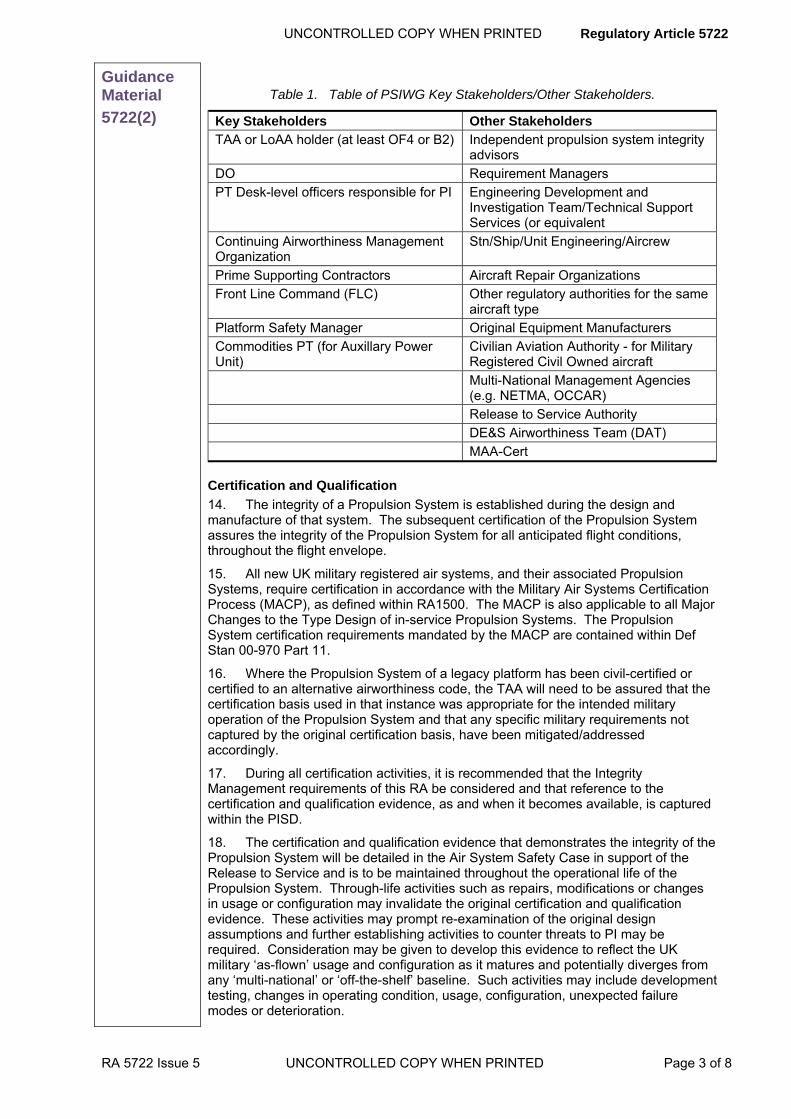
UNCONTROLLED COPY WHEN PRINTED Regulatory Article 5722
RA 5722 Issue 5 UNCONTROLLED COPY WHEN PRINTED Page 3 of 8
Guidance Material
5722(2)
Table 1. Table of PSIWG Key Stakeholders/Other Stakeholders.
Key Stakeholders Other Stakeholders TAA or LoAA holder (at least OF4 or B2) Independent propulsion system integrity
advisors
DO Requirement Managers
PT Desk-level officers responsible for PI Engineering Development and Investigation Team/Technical Support Services (or equivalent
Continuing Airworthiness Management Organization
Stn/Ship/Unit Engineering/Aircrew
Prime Supporting Contractors Aircraft Repair Organizations
Front Line Command (FLC) Other regulatory authorities for the same aircraft type
Platform Safety Manager Original Equipment Manufacturers
Commodities PT (for Auxillary Power Unit)
Civilian Aviation Authority - for Military Registered Civil Owned aircraft
Multi-National Management Agencies (e.g. NETMA, OCCAR)
Release to Service Authority
DE&S Airworthiness Team (DAT)
MAA-Cert
Certification and Qualification
14. The integrity of a Propulsion System is established during the design and manufacture of that system. The subsequent certification of the Propulsion System assures the integrity of the Propulsion System for all anticipated flight conditions, throughout the flight envelope.
15. All new UK military registered air systems, and their associated Propulsion Systems, require certification in accordance with the Military Air Systems Certification Process (MACP), as defined within RA1500. The MACP is also applicable to all Major Changes to the Type Design of in-service Propulsion Systems. The Propulsion System certification requirements mandated by the MACP are contained within Def Stan 00-970 Part 11.
16. Where the Propulsion System of a legacy platform has been civil-certified or certified to an alternative airworthiness code, the TAA will need to be assured that the certification basis used in that instance was appropriate for the intended military operation of the Propulsion System and that any specific military requirements not captured by the original certification basis, have been mitigated/addressed accordingly.
17. During all certification activities, it is recommended that the Integrity Management requirements of this RA be considered and that reference to the certification and qualification evidence, as and when it becomes available, is captured within the PISD.
18. The certification and qualification evidence that demonstrates the integrity of the Propulsion System will be detailed in the Air System Safety Case in support of the Release to Service and is to be maintained throughout the operational life of the Propulsion System. Through-life activities such as repairs, modifications or changes in usage or configuration may invalidate the original certification and qualification evidence. These activities may prompt re-examination of the original design assumptions and further establishing activities to counter threats to PI may be required. Consideration may be given to develop this evidence to reflect the UK military ‘as-flown’ usage and configuration as it matures and potentially diverges from any ‘multi-national’ or ‘off-the-shelf’ baseline. Such activities may include development testing, changes in operating condition, usage, configuration, unexpected failure modes or deterioration.

Regulatory Article 5722 UNCONTROLLED COPY WHEN PRINTED
Page 4 of 8 UNCONTROLLED COPY WHEN PRINTED RA 5722 Issue 5
Guidance Material
5722(2)
Critical Engine Components
19. A critical engine component is one which is required to achieve and maintain a high degree of integrity, as its failure has been identified, through failure analysis, as having the potential to result in a hazardous engine effect. Hazardous engine effects are those which have been defined by the European Aviation Safety Agency (EASA) within the Certification Specification for Engines and are regarded as:
a. Non-containment of high-energy debris.
b. Concentration of toxic products in the Engine bleed air for the cabin sufficient to incapacitate crew or passengers.
c. Significant thrust in the opposite direction to that commanded by the pilot.
d. Uncontrolled fire.
e. Failure of the Engine mount system leading to inadvertent Engine separation.
f. Release of the propeller by the Engine (if applicable).
g. Complete inability to shut down the Engine.
20. The DO is required to identify the critical components contained within the Propulsion System and provide appropriate life management details. The TAA may accept and authorize the DO’s recommendations and promulgate the lifing within the Aircraft Document Set (ADS).
Component Lifing
21. Where condition monitoring cannot anticipate the failure of a component, a life will need to be formulated as required by Def Stan 00-970, Part 11. Lives of components need to be proposed to the PT by the DO or an approved competent organization (RA1005). Consideration is also to be given to shelf, storage and inhibited lives of components.
22. The conversion of actual usage into the common currency of reference cycles is achieved through the use of exchange rates. Instances where the Propulsion System has twin (or multiple) populations (’fleets within fleets’), each exchange rate will be managed separately.
23. The component lives and exchange rates proposed by the DO or competent organization will be verified for compliance to the minimum standards prior to formal approval. Authority for their approval and promulgation is vested in the TAA. In addition, PTs may promulgate component lives and exchange rates in the ADS.
24. The Statement of Operating Intent (SOI) is the means by which the future operating intent for a particular aircraft type and major mark are conveyed formally to the DO by the MOD. The Statement of Operating Intent and Usage (SOIU) replaces the SOI when the aircraft has accumulated sufficient in-service usage data. Consideration will be given to how initial/changing sortie profiles and standard operating procedures impact upon the Propulsion Systems of an aircraft.
Capturing PI risks
25. Within an Air System Safety Case and through the introduction of an ASMS, it is necessary to assess the hazards that a Propulsion System can present to a platform and to ensure the risks posed by these hazards are Tolerable and ALARP (see RA1220 Project Team Airworthiness and Safety). These risks will be reported up to the platform level hazard analysis. For further information on Engine Hazardous effects see Def Stan 970 Part 11
Regulation
5722(3)
Sustaining Propulsion Integrity 5722(3) The TAA shall monitor, measure and counter threats in order
to sustain PI.

UNCONTROLLED COPY WHEN PRINTED Regulatory Article 5722
RA 5722 Issue 5 UNCONTROLLED COPY WHEN PRINTED Page 5 of 8
Acceptable Means of Compliance
5722(3)
Sustaining Propulsion Integrity 26. PI should be reviewed and managed through the bi-annual PSIWG process and reported to the appropriate Airworthiness Management Group (AMG).
27. Propulsion system configuration control should be managed.
28. The following data should be accurately captured and recorded by the users:
a. Usage data.
b. Failure data.
29. Health monitoring should be carried out by the users.
30. Support Policy Statement (SPS) and Maintenance Schedules should be managed and maintained.
31. Obsolescence should be managed.
32. The Propulsion system should be included in the Ageing Aircraft Audit (RA5723: Ageing Aircraft Audit).
33. Any unmitigated or unquantified airworthiness risks should be identified to the PSP/PSWG.
34. The PSIWG should endorse the strategies and plans to mitigate the risks to PI.
Guidance Material
5722(3)
Sustaining Propulsion Integrity PSIWG
35. The objectives of a PSIWG are to:
a. Enable the management of PI to be ratified and assessed in accordance with MOD propulsion regulation and reported upward to the relevant AMG.
b. Review PI management processes commensurate with the aircraft’s position in its lifecycle, taking into account projected usage and known risks.
Configuration Control
36. Failure to maintain Propulsion System configuration control may have an adverse effect on PI and airworthiness. During its operational life the Propulsion System configuration of in-service aircraft may diverge from the as‑built standard, as individual aircraft and equipment are subject to: Service Instructions (Technical), damage, repairs, obsolescence, modifications and mid-life updates; this is not a comprehensive list. All critical components require to have a record of consumed life that include details of component installation in module, engine (or accessory) and aircraft. The PT may contract out configuration control management but the TAA retains the responsibility to ensure that a configuration control system is maintained in service.
Data Collection
37. The DO requires in-service, as flown usage parameter data (e.g. Turbine Blade Temperature and Engine Speed N1) in order to monitor and evaluate component lives and Maintenance Schedules.
38. PTs also require in-use failure data in order to ascertain actual failure rates. This will allow Maintenance Schedules to be implemented to extend Mean Time Between Failures, or to enable the component to be replaced before any predicted failure.
39. The TAA is required to ensure that the necessary information is captured by the FLCs and sent to the DO for analysis, which may result in a re-calculation of component life.
Health Monitoring
40. Health monitoring may allow prediction when any tolerance or parameter will be exceeded. Degradation may be unnoticeable by the operator and only become apparent during maintenance, testing, or via information provided by a third party. In

Regulatory Article 5722 UNCONTROLLED COPY WHEN PRINTED
Page 6 of 8 UNCONTROLLED COPY WHEN PRINTED RA 5722 Issue 5
Guidance Material
5722(3)
accordance with RA 4000 series, arrangements must be put in place to allow the health of the Propulsion System to be monitored throughout its operating life. Methods of health monitoring may include vibration analysis, performance runs and wear debris analysis.
SPS/Maintenance Schedule
41. The correct and timely application of preventive maintenance, supported by the SPS and Maintenance Schedule, underpins PI. The SPS must be periodically reviewed iaw RA4200 series. Aero engines are often subject to scheduled maintenance regimes (e.g. component inspections). Any latitude in scheduled maintenance intervals will be determined through consultation with the DO.
Obsolescence
42. PTs will manage obsolescence in line with JSP886: Def Logs Support Chain Manual Vol 7 – Supportability Engineering, Part 8.03B – Maintenance Design which requires an obsolescence management plan as part of the Project TLMP. The PT may contract out obsolescence management, but the TAA retains overall responsibility.
Regulation
5722(4)
Validating Propulsion Integrity 5722(4) The TAA shall ensure that the assumptions underpinning PI
are periodically validated.
Acceptable Means of Compliance
5722(4)
Validating Propulsion Integrity 43. The SPS and Maintenance Schedules should be reviewed and updated.
44. The DO should review the validity of design and usage assumptions at a periodicity determined by the DO, and also in conjunction with any SOIU review.
45. The need for, and potential scope of, sampling in support of validating activities should be determined and published.
Guidance Material
5722(4)
Validating Propulsion Integrity SPS and Maintenance Schedules
46. Due to changeable operational requirements the validity of the Maintenance Schedule and expected component lives within the design assumptions need to be verified. In addition, an SPS review will need to be carried out and will include a review of the ADS and any supporting procedures.
Design and Usage
47. Actual usage data gathered from the as‑flown configuration will be used to validate or refine the DO’s assumptions. In-use experience of all aircraft systems, including that of other users, may reveal different failure modes and component lives than those originally predicted by the DO. Failure rates are generally indicative of the design assumptions, however where they deviate significantly, consideration will be given to amending the DO’s assumptions to reflect the revised failure rates. The impact of any component life or usage changes on critical parts transferred between operations will need to be clearly understood by PI stakeholders and would be expected to be reviewed as part of any validation activity. For clarity, the PI strategy may capture the measures to be taken regarding transfer of critical parts between operational fleets.
Sampling
48. Sampling is to be actively managed by the PT so that any deviation from the design specification can be identified and necessary recovery action captured by the PT. Any sampling requirements are to be published in an appropriate document. Arrangements are to be made for collating and interpreting sampling results and sampling targets. Laboratory sample inspections will be carried out on retired components at specified intervals with a final inspection carried out on components at
UNCONTROLLED COPY WHEN PRINTED Regulatory Article 5722
RA 5722 Issue 5 UNCONTROLLED COPY WHEN PRINTED Page 7 of 8
Guidance Material
5722(4)
full life or retirement. Ideally all components need to be inspected at the end of their lives, but the DO or TAA may decide the quantity of life-expired or retired components to be inspected. Effects due to environment, maintenance and operating characteristics that impact upon component integrity can be monitored in order to enhance the level of safety. Since long periods of time can elapse before cyclic inspections are due, it is important that all intermediate opportunities to assess calendar life and wear effects on components are used to the full. All component inspections during maintenance, repair and overhaul will be logged as this may preclude the need for component withdrawal for sample inspections.
49. As per Def Stan 00-970 Part 11, the periodic completion of a Technical Life Review by the DO would be expected as part of any validation activity, in order to underwrite or revise critical part lives and define any actions necessary for continued safe operation.
Regulation
5722(5)
Recovering Propulsion Integrity 5722(5) The TAA shall ensure PI is recovered following any loss of,
or potential compromise to PI.
Acceptable Means of Compliance
5722(5)
Recovering Propulsion Integrity 50. The following events should be immediately reported to the TAA:
a. Any perceived reduction in the Propulsion System availability or performance.
b. Any loss of, or compromise to, PI that is judged to have the potential to occur on other aircraft within the fleet.
c. Any change in Propulsion System usage patterns.
51. Arrangements should be made with the DO and, where practicable, external operators to obtain notification of Propulsion System occurrences with potential read-across.
52. Significant Propulsion System arisings should be reported and evaluated at the PSIWG.
53. Measures should be taken to recover PI, taking specialist advice from the DO or independent advisors following any triggering events.
Guidance Material
5722(5)
Recovering Propulsion Integrity PI Reporting
54. Type-specific procedures will be published within the ADS detailing the action to be taken following loss or compromise to PI.
PI Evaluation
55. Where a loss or compromise has been identified/reported an investigation into, and recovery of, significant damage or failure will be monitored by the PSIWG.
PI Recovery
56. Recovery measures may include repairs, modifications, additional examinations or testing, changes to component lives, or the imposition of operating restrictions. Additionally, the results of validation activities and in-service experience may bring fleet-wide PI into question, which may reinforce any imposed operating restrictions. Any requirement to impose operating restrictions would need to be agreed with the relevant Aircraft Operating Authority. Following a loss of PI it may be necessary to quantify risk and generate recovery options. Component modifications that alter the performance of the Propulsion System (e.g. increasing shaft speed) may affect other components in the system and the impact on those components affected will need to be assessed. Although critical component fatigue lives are usually considered to be finite, in exceptional circumstances and in order to manage a platform back to ALARP,

Regulatory Article 5722 UNCONTROLLED COPY WHEN PRINTED
Page 8 of 8 UNCONTROLLED COPY WHEN PRINTED RA 5722 Issue 5
Guidance Material
5722(5)
the TAA may, in consultation with the DO, authorize critical part life extensions. This extreme action is to be carefully considered by the TAA if it is to be included as part of a recovery plan as it can, in itself, trigger a further reduction in confidence in PI.
Regulation
5722(6)
Exploiting Propulsion Integrity 5722(6) The TAA shall ensure PI is exploited to take full advantage
of the aircraft Propulsion System.
Acceptable Means of Compliance
5722(6)
Exploiting Propulsion Integrity 57. In-service experience of other platforms or operators should be utilised.
Guidance Material
5722(6)
Exploiting Propulsion Integrity Utilising in-service experience
58. Data from other platforms or operators whether UK military, overseas military or civil operators, may be exploited by PTs to further support PI activities, subject to the following considerations:
a. The period and nature of operations considered is to be broadly representative of UK military usage.
b. The current and expected UK military operating envelope is to be either benign in comparison with that of other users or the future operating envelope is to be restricted as necessary.
c. The effect of any configuration differences between the aircraft and/or engines being compared.

UNCONTROLLED COPY WHEN PRINTED Regulatory Article 5723
RA 5723 Issue 3 UNCONTROLLED COPY WHEN PRINTED Page 1 of 12
►This RA has been substantially re-written; for clarity, no change marks are presented - please read RA in entirety◄
RA 5723 - Ageing Aircraft Audit
Rationale The risk to airworthiness due to the ageing of aircraft in service is partly mitigated by Integrity Management in accordance with RA 5720, RA 5721 and RA 5722. However, the insidious nature of degradation and the interaction of apparently unrelated ageing processes are often found only by an additional rigorous periodic audit of trend data, procedures and the aircraft's physical condition. This whole process is known as an Ageing Aircraft Audit and it is achieved by observing the regulation and guidance in this Regulatory Article.
Contents 5723(1): Ageing Aircraft Audit
Regulation
5723(1)
Ageing Aircraft Audit 5723(1) All UK military registered aircraft types shall be subjected to
an Ageing Aircraft Audit (AAA), to give confidence that airworthiness risks are at least tolerable and As Low As Reasonably Practicable (ALARP), as the fleet ages and regulatory requirements evolve.
Acceptable Means of Compliance
5723(1)
Ageing Aircraft Audit 1. The Type Airworthiness Authority (TAA) should initiate an independent AAA for each ageing aircraft fleet under their control 15 years after a type’s declared In Service Date (ISD), or at the mid-point between the declared ISD and the initial planned Out of Service Date (OSD) whichever is soonest. Repeat audits should be conducted at 10-year intervals thereafter.
2. The AAA should cover the airworthiness and Integrity Management of the aircraft, giving particular consideration to ageing. TAAs should identify the areas to be covered by Structures, System and Propulsion Audits based on the safety consequences of potential failure and analysis of information from all available resources.
3. It should be clearly stated which aircraft areas or systems, if any, are to be excluded from the AAA and the rationale for their exclusion.
4. The AAA should include items managed by commodity Project Teams (PTs), where necessary. The aircraft PT should take primacy in the Audit, seeking commodity PT support as necessary.
5. A detailed, independent physical examination of the condition and husbandry standards of representative aircraft (and, where appropriate, sub-systems) from the fleet should be carried out.
6. Any audit activity should be completed and a report, to include recommendations, issued, within a 2-year period.
Guidance Material
5723(1)
Ageing Aircraft Audit Background
7. Aircraft structure, aircraft systems and propulsion systems have to function as intended throughout the operational envelope of the aircraft, taking due account of the operating environment. The Design Organization (DO) makes assumptions about usage, loads and the threats to Structural, System and Propulsion Integrity during the

Regulatory Article 5723 UNCONTROLLED COPY WHEN PRINTED
Page 2 of 12 UNCONTROLLED COPY WHEN PRINTED RA 5723 Issue 3
Guidance Material
5723(1)
design and certification process. The assurance of Integrity Management in these areas through life is covered by RA 5720, RA 5721 and RA 5722, respectively.
8. During the life of an aircraft, cumulative exposure to the threats to Integrity (such as overload, fatigue, environmental/accidental damage, absence of configuration control, or maintenance/supply errors), and the risk of them interacting, increase with time and usage. Additionally, calendar-based ageing mechanisms (such as the effects of environmental ageing and degradation) can compromise Integrity. The effects of ageing are not always comprehensively recognised or addressed by routine activities.
9. The AAA can be subdivided into Audits covering aircraft structure, aircraft systems and propulsion systems, each considering different failure modes and airworthiness consequences:
a. Structural Airworthiness can be compromised by unexpected structural degradation. This often occurs in-service due to interacting damage mechanisms that were either not anticipated or not taken into account in testing. Such interacting mechanisms may include the combined effects of fatigue with corrosion, disbonds, impact damage or multiple adjacent repairs. Furthermore, for high-life aircraft, fatigue cracks may nucleate and grow from multiple sites and then coalesce to form a single, critical crack earlier than would have been estimated using conventional crack growth analyses.
b. System Airworthiness can be compromised by systems failure rates which exceed those assumed in the Safety Case; the unexpected interaction of failed systems; and the undetected failure of critical or emergency systems.
c. Propulsion system failure can directly affect the airworthiness of the aircraft or the integrity of the engine. The manner in which the ageing effects manifest themselves is dependent on the material from which the components are manufactured and the threats to Propulsion Integrity to which the components have been exposed.
10. Sources of information may include design evidence, component criticality analysis, zonal hazard analysis, functional hazard analysis, functionally significant item analysis, system safety assessments, results of aircraft physical and husbandry inspections, functional surveys and failure and reliability data.
11. It may become increasingly difficult to support ageing aircraft, as the Original Equipment Manufacturers (OEMs) may not be able to support or supply an exact replacement for an item. Effective obsolescence management (see JSP 886 Vol 7), including changes in legislation or specifications (which alter or ban the use of specific materials, substances or processes), becomes increasingly important for ageing aircraft.
12. Additionally, over time there may be loss of corporate aircraft platform knowledge, loss of configuration control, changes in assumed usage, evolution of regulatory requirements and the accumulated effects of a number of otherwise minor integrity problems.
13. The AAA is therefore necessary to identify and manage, at an at least tolerable and ALARP level, the airworthiness risks as a fleet ages and regulatory requirements evolve. As a beneficial consequence, it can also help to optimise fleet availability and support costs.
Aim of AAA
14. An AAA provides assurance that the Structural Integrity, System Integrity and Propulsion Integrity, and hence the airworthiness risks, of a fleet’s aircraft are being managed appropriately from the perspective of ageing. Therefore the aims of an AAA are to:
a. Conduct a periodic, independent assessment of the airworthiness of the fleet, with particular consideration to ageing.
b. Consider individually and collectively the Structural Integrity, System Integrity and Propulsion Integrity activities, often carried out in isolation, in order to assess the effectiveness of the fleet’s airworthiness management.

UNCONTROLLED COPY WHEN PRINTED Regulatory Article 5723
RA 5723 Issue 3 UNCONTROLLED COPY WHEN PRINTED Page 3 of 12
Guidance Material
5723(1)
c. Undertake an independent review of the continued applicability of procedures, management processes, assumptions and documentation that are in place to ensure airworthiness, integrity and functionality.
d. Undertake a detailed, independent physical examination of the condition of representative aircraft from the fleet, unless an equivalent examination is conducted routinely.
e. Identify patterns or trends that suggest future airworthiness and integrity problems.
f. Identify significant risks to the airworthiness and integrity of the aircraft and to the achieving of its planned OSD.
Timing of AAA
15. The following points will need to be considered when deciding the timing of an AAA:
a. The '15 years after ISD' requirement is applicable to aircraft fleets which are acquired from new. Where fleets are acquired which have been previously owned or operated, then an AAA is to be undertaken at an earlier stage; advice may be sought from independent specialists, where contracted, and MAA-Cert-Div. In the case of the acquisition of a fleet which can already be regarded as ageing, an AAA is to be conducted before Main Gate approval is sought.
b. Fleets acquired under short-duration arrangements would not usually be expected to undertake an AAA, provided no member of the fleet is anticipated to exceed 50% of its cleared life (in any parameter) during MOD service. Advice may be sought from independent specialists, where contracted, and MAA-Cert-Div in deciding whether short-duration fleets are to be subjected to an AAA, and again this has to be before Main Gate approval is sought.
c. If the original planned OSD is to be extended, the mid-life point (for conducting the first AAA) is to be based upon the original OSD forecast when the Type Certificate or initial Release to Service was signed.
Use of comparable programmes
16. Some aircraft may have in place comparable programmes to AAAs that have been developed by OEMs, civil operators or foreign armed services, which might fulfil many requirements of an AAA.
17. Where the subject fleet is a civil derivative and is operated in a manner essentially similar to the civil role, a comparison may be conducted between the documentation produced to meet the civil continuing airworthiness requirements for ageing aircraft structure, aircraft systems and propulsion systems and the AAA regulation contained in this RA. The results of the comparison may reduce the amount of work needed to fulfil the AAA requirement.
18. In accepting other programmes as being suitable to meet the AAA requirement, TAAs have to satisfy themselves, through consultation with independent specialists and MAA-Cert-Div, that the programme meets the requirements of this RA. Requests for recognition of comparable programmes have to be submitted by the TAA for endorsement by MAA-Cert-Div at least 12 months prior to the audit becoming due.
Management of AAA: Coordination
19. The TAA may appoint an AAA Coordinator who is responsible for controlling the interfaces between the Audits and for coordinating the AAA results. A list of all Audits and the demarcation between them will be included in an AAA Coordination Document.
20. Some aircraft systems components include items considered to be structure (eg propellers and helicopter rotor blades). The TAA will decide under which Audit(s) these items are addressed.
21. Where Audit requirements to examine aircraft may lead to other systems being disturbed, these are to be identified in the AAA Coordination Document and their consideration planned within the overall work programme.

Regulatory Article 5723 UNCONTROLLED COPY WHEN PRINTED
Page 4 of 12 UNCONTROLLED COPY WHEN PRINTED RA 5723 Issue 3
Guidance Material
5723(1)
Management of AAA: Requirements
22. The potential size, complexity and cost of an AAA make careful planning and management essential. The following factors will be important in this consideration:
a. Each specialist area may be managed by an AAA Working Group comprising representatives from the aircraft PT, relevant commodity PTs, DO, maintenance organizations, OEMs and independent specialist airworthiness advisers.
b. The TAA, in consultation with the AAA Coordinator, may appoint Project Officers who are responsible for specialist areas (eg structures, systems or propulsion) within the AAA.
c. An independent specialist airworthiness adviser, who is a Subject Matter Expert in an aircraft system, will usually be appointed by the TAA to cover each specialist area.
d. The adviser may also:
(1) Advise the PT on the scope of the AAA.
(2) Assess proposals for AAA activity on behalf of the PT.
(3) Conduct the AAA if contracted to do so.
(4) Assist the PT to interpret the outcomes of the AAA.
(5) Support the AAA Working Group.
e. The AAA will require a range of personnel with adequate technical knowledge of aircraft structure, aircraft systems and propulsion systems and of the safety assessment methods employed (such as Hazard Assessment, Failure Modes and Effects Analysis, Failure Modes Effects and Criticality Analysis (FMECA) and aircraft service history trend analysis). Extensive OEM data may be required.
f. The Audit team will need appropriate access to records and information, which may include DO/OEM data, in order to carry out the AAA.
23. The requirement to conduct an AAA and subsequent repeats will normally be reflected in the aircraft’s Through Life Management Plan (TLMP) and relevant integrity strategy documents.
Management of AAA: Tasking
24. The AAA can be carried out by either the aircraft DO or another independent organization.
25. If the Audit is to be carried out by the DO or an organization which is already engaged in managing, maintaining or advising on the fleet’s airworthiness, then additional measures are necessary to ensure that the independence of the AAA is not compromised. Accordingly, those personnel conducting, supervising and approving the Audit need to be separate from the chain of responsibility for those supporting the fleet’s airworthiness.
26. In the case of sub-systems, the sub-system DO may be tasked separately to undertake audit activity as necessary. The TAA is responsible for selecting and tasking organizations that are competent and independent.
27. The DO/OEM may also:
a. Advise the PT on the scope of the AAA.
b. Provide records and data as required by the Audit Team.
c. Assist the PT to interpret the outcomes of the AAA.
d. Support the AAA Working Group.
Reporting
28. A final AAA Report, covering all Audits, will be produced and accepted before the AAA can be considered complete; the Report will include recommendations. Advisers, DOs and OEMs, where contracted, may assist the TAA to interpret the AAA report and findings. Additionally, generic aircraft airworthiness and cross-platform

UNCONTROLLED COPY WHEN PRINTED Regulatory Article 5723
RA 5723 Issue 3 UNCONTROLLED COPY WHEN PRINTED Page 5 of 12
Guidance Material
5723(1)
risks identified by the AAA are to be reported by the TAA to the appropriate Airworthiness Management Group.
Follow-up actions
29. The TAA will sentence the recommendations in the AAA Report and initiate appropriate follow-up action, ensuring that all identified hazards are at least tolerable and ALARP. The risks are to be managed via the TAA’s Safety Management System. Progress against the recommendations and hazards is to be monitored by the Project Safety Working Group (PSWG) or Integrity Working Groups. The TAA may consider the benefits of producing a report on 'Lessons Identified' from the AAA activity.
Scope of AAA
30. Careful scoping of the AAA is essential. This is to ensure that Audit activities are integrated in order to properly address all aspects and avoid nugatory work. The Audit will include, but need not be limited to:
a. Issues revealed by any earlier AAAs on the fleet.
b. Complexity of the platform to be audited: generally, greater complexity requires more detailed planning and scoping.
c. Potential for collaboration with other users.
d. Equipment managed by organizations external to the TAA, eg commodity PTs.
e. Effect of fleet size, roles and mini-fleets: ensure that the AAA accounts for differences in roles and marks.
f. Availability and veracity of usage data.
g. Configuration control methods.
h. Known or perceived manufacture, repair or supply errors.
i. The completion and effectiveness of sampling programmes, for whole aircraft or components, whether non-destructive or destructive. Note that destructive sampling and forensic examination is not a mandated element of AAA per se, but the need for it may become apparent during an AAA.
j. In respect of the independent physical examination of the aircraft condition and husbandry standards, independence may be achieved through the examination being undertaken by experienced aircraft engineering personnel from appropriate trades who are familiar with military aircraft engineering practices but not currently employed on-type. If existing continuing airworthiness processes, already incorporated into fleet procedures, eg Baseline Military Airworthiness Review, are used to support compliance, care is to be taken that their scope is expanded as necessary in order to meet that required of an AAA. This physical examination is mandated, in order to:
(1) Check that the actual condition of the fleet matches the official record.
(2) Detect hidden faults and those masked by poor husbandry.
(3) Provide assurance that standards of husbandry, maintenance and, ultimately, airworthiness are acceptable.
(4) Check the condition of interconnections. A final Interconnectivity Condition Survey report is to contain recommendations about further sampling, including destructive sampling where appropriate. For further guidance, see Reference j.
k. An assessment of the adequacy of PT procedures and maintenance policies for, but not limited to, the following:
(1) Fault arisings, trends and reports.
(2) Sampling.
(3) Technical Instructions, Service Bulletins and Airworthiness Directives.

Regulatory Article 5723 UNCONTROLLED COPY WHEN PRINTED
Page 6 of 12 UNCONTROLLED COPY WHEN PRINTED RA 5723 Issue 3
Guidance Material
5723(1)
(4) Management of DO/OEM advice.
(5) Other user evidence.
(6) Retention of airworthiness documentation.
(7) Maintenance schedule review, maintenance programme review or equivalent.
(8) Obsolescence management strategy and plans in accordance with JSP 886 Vol 7.
(9) Usage Monitoring.
(10) Supplementary Inspection Programmes.
(11) The Aircraft Document Set (ADS).
(12) Those items categorised 'on condition' that may not otherwise be routinely considered.
l. A review of the Hazard Log and Risk Register entries of any status, whether open, approved, managed or closed.
m. A review of the Limitation and Acceptable Deferred Fault Logs for a representative selection of aircraft from the fleet to check their significance, validity, safety, quantity and potential interaction.
n. The effectiveness of the Depth Maintenance programme in rectifying Limitations and Acceptable Deferred Faults.
o. The effectiveness of maintenance schedule reviews to ensure that technical documentation is up to date and consistent.
p. The use of new techniques and technologies to capture Ageing Aircraft issues across all maintenance levels.
q. The existence, effectiveness and findings of any other ageing aircraft programmes (such as those conducted under civilian regulations) which are applicable to the fleet. Such programmes may be of particular relevance to fleets based upon civil aircraft.
r. Proximity to OSD: if nearing the OSD then the extent of the AAA will be set using a risk-based approach, while taking into account the possibility of OSD extension (see RA 5725).
s. Continued validity of Life Extension Programme evidence where applicable (see RA 5724).
t. A review of assumptions used in generating lives and inspection schedules, including monitoring and management of changes in operational conditions and usage.
31. The scope for the structural, systems and propulsion aspects of the AAA may be proposed by the respective AAA or Integrity Working Groups and is to be agreed by the TAA. Advisers, DOs and OEMs, where contracted, may advise the PT on the scope of the AAA.
32. Emerging findings are to be reviewed periodically by the appropriate Working Group. Working Groups may report progress to the TAA, refine the scope of the Audit using a risk-based approach and raise issues arising from an AAA to the appropriate aircraft PSWG.
Scope: Ageing Aircraft Structural Audit
33. For the definition of Structure, see RA 5720(1). The recommendations within MASAAG Paper 104 are to be referred to when setting the scope of the Structural Audit (MASAAG Paper 104 is available from MAA-Cert-Div). In addition to the general AAA requirements, the Structural Audit will include, but need not be limited to:
a. Effectiveness and currency of Structural Integrity Strategy Document and Plans.
b. Adequacy of all published structural information for the type design,

UNCONTROLLED COPY WHEN PRINTED Regulatory Article 5723
RA 5723 Issue 3 UNCONTROLLED COPY WHEN PRINTED Page 7 of 12
Guidance Material
5723(1)
including:
(1) Currency, completeness and accuracy of static loads and fatigue qualification documents, such as the Static and Fatigue Type Records.
(2) Existence of an appropriately derived list of Structurally Significant Items (SSIs) or equivalent.
c. Relevance, currency and results of structural monitoring and Individual Aircraft Tracking, including any fatigue budgeting decisions and implementation.
d. In-service structural arisings and recovery programmes:
(1) Effectiveness of response.
(2) Extent and adequacy of trend identification and monitoring.
e. Existence and effectiveness of the Structural Examination Programme (SEP), and confirmation that all SSIs are included in the SEP.
f. Structural configuration management process, including:
(1) Existence, adequacy, use and effectiveness of structural configuration control databases and records of repair.
(2) Assessment of through-life airworthiness of repairs (eg their static strength and fatigue clearance). Confirm and consider the effects on strength, repair lives and inspection intervals of: environmental degradation, changes in aircraft usage severity, life extension, repair proximity and repair interaction.
g. Consider the need for a Repair Assessment Programme. See MASAAG Paper 106 (MASAAG Paper 106 is available from MAA-Cert-Div).
h. Existence and adequacy of a comprehensive Environmental Damage Prevention and Control Programme in accordance with RA 5720(3).
i. Each type’s susceptibility to Widespread Fatigue Damage and the existence of programmes for corrective action.
j. Effective validation of assumptions used in generating structural lives and inspection schedules, such as:
(1) Operational Loads Measurement, Operational Data Recording and Manual Data Recording Exercise programmes.
(2) Statement of Operating Intent and Usage reviews.
(3) Destructive sampling and forensic examination.
(4) Assessment of Structural Integrity implications of the actual standards of maintenance and husbandry.
(5) Supplementary Structural Inspection Programmes.
k. The overall rationalisation of maintenance schedules to accommodate each of the items detailed at sub-paragraphs a to j above.
l. Structural Hazard Log and Risk Register:
(1) Effectiveness of process for management of structural risks.
(2) Continued validity of hazard mitigation assumptions, including inspections.
(3) Review of all entries, whether open, approved, managed or closed.
Scope: Ageing Aircraft System Audit
34. The System Audit will cover systems, assemblies, parts and interconnections that are affected by ageing and are critical to airworthiness, for example:
a. Emergency systems and systems with a critical function.
b. Mechanical systems: flight control, fuel, hydraulic, cooling, pneumatic, landing gear, environmental control, air services, ice and rain protection, water injection, oxygen, nitrogen, water/waste, target towing, arrester, equipment and

Regulatory Article 5723 UNCONTROLLED COPY WHEN PRINTED
Page 8 of 12 UNCONTROLLED COPY WHEN PRINTED RA 5723 Issue 3
Guidance Material
5723(1)
furnishings, propeller gearbox and pitch control systems.
c. Avionic systems: primary and secondary radars, data buses, electro-optics, photographic, defensive aids, navigation aids, communications, data links, electronic warfare, identification, traffic collision and avoidance, air traffic management aids, electrical power generation and distribution, weapon control and release, air data, displays, prognostics and health management, mission planning, flight control, and all wiring interconnections and connectors.
d. Electronic systems including Complex Electronic Hardware.
e. Secondary Power System.
35. In addition to the general AAA requirements, the System Audit will include, but need not be limited to:
a. Systems whose failure could affect another system (whether or not the latter had also failed) and hence adversely affect airworthiness.
b. Installed combustible materials and flammability especially insulation materials and non metallic cladding.
c. Existence of any evidence from thermal mapping in the platform safety case.
d. Obsolescence issues affecting components within electronic control systems.
e. Whether the memory in any programmable devices is still reliable and appropriate for the task.
f. Whether the system protection from lightning strikes, High Intensity Radiated Fields (HIRF) and Electromagnetic Compatibility (EMC) is still acceptable, with no degradation in grounding or cable shielding.
g. Whether product software development tools (including rigs), knowledge, training programmes and skilled software engineers are still in place to upgrade software if needed.
h. Appropriateness of design assumptions and certification basis, supported by evidence, which together underpin the integrity of each aircraft system.
i. The TLMP and integrity strategy regarding:
(1) The effectiveness of solutions to previous recommendations.
(2) The adequate planning and recording of future activities.
j. The existence, adequacy, use and effectiveness of the systems configuration control process including all usage history, life consumption, modifications, repairs and concessions.
k. The changes in operational conditions and usage during the life of the aircraft and how the differences have been, and plan to be, monitored and managed.
l. Effectiveness and currency of System Integrity Strategy Document and Plans.
36. Expendable stores, Air Launched Weapons and carry-on items are not covered by this regulation. Information on certification and release can be sought from the responsible PT or from the Defence Ordnance Safety Group.
Scope: Ageing Aircraft Propulsion Audit
37. For the definition of Propulsion System, see MAA02. The Propulsion Audit will cover independent audit of the aircraft engine(s), engine control systems, engine casing, functional and physical aircraft/engine and propeller/engine interfaces (including fuel and oil system interfaces, electrical harnesses and thrust reverse system where not considered under the scope of the System or Structural Audits) and Auxiliary Power Unit.
38. In addition to the general AAA requirements, the Propulsion Audit will include, but need not be limited to:

UNCONTROLLED COPY WHEN PRINTED Regulatory Article 5723
RA 5723 Issue 3 UNCONTROLLED COPY WHEN PRINTED Page 9 of 12
Guidance Material
5723(1)
a. A Propulsion Integrity Management review.
(1) Assess the effectiveness of solutions to previous safety-related recommendations, to include but not be limited to OEM advice, or observations from previous audits or safety reviews.
(2) Assess the adequacy of planning and recording of Integrity Management activities against Propulsion Integrity requirements, and their inclusion in the platform level Safety Management Plan.
b. A documentation review. Confirm that all technical documents, including but not limited to the following, are up to date and consistent with each other and the ADS:
(1) Operating Conditions and Limitations, Engine Operating Conditions.
(2) Engine Technical Certificate, Type Approval Certificate or equivalent.
(3) Life Management Plan.
(4) Engine operating instructions.
(5) Maintenance manuals.
(6) Technical Instructions.
c. A review of propulsion configuration control processes.
(1) Check the existence, adequacy, use and effectiveness of usage and life consumption data.
(2) Establish if there is a process in place for managing component repairs if conducted outside DO approval.
(3) Assess the effectiveness of the process for managing concessions.
(4) Assess the extent and adequacy of scrap procedures (to ensure that all scrap items are removed from service).
(5) Assess the process for managing cannibalisation and its adequacy, in terms of configuration management.
(6) Evaluate the quality and accuracy of electronic component tracking systems.
d. An assessment of product usage.
(1) Check that the product is being used as intended by the latest endorsed operating conditions, including operational and environmental conditions.
(2) Confirm that the PT has reviewed and checked that all the assumptions made during initial product qualification are still valid, including aircraft to engine loads, off takes, engine bay clearances, vibration levels, thermals and intake effects, as appropriate. DO access may be required and will need to be arranged accordingly.
(3) Confirm that there is an adequate and working process in place to ensure that any modifications to the aircraft or systems, which could influence the engine (including electrical changes that may have an impact on EMC capabilities), are brought to the attention of the OEM.
e. A maintenance policy review.
(1) Review of on-condition-based maintenance policy, including physical inspection of items not normally inspected, eg aircraft/engine and propeller/engine interface components, electrical harnesses, casings, etc.
(2) Confirm that the maintenance periodicity for each module and system has been verified and deemed appropriate by the engine DO following in-service findings and has demonstrated reliability.

Regulatory Article 5723 UNCONTROLLED COPY WHEN PRINTED
Page 10 of 12 UNCONTROLLED COPY WHEN PRINTED RA 5723 Issue 3
Guidance Material
5723(1)
(3) Review of Scheduled Servicing Policy.
(4) Review of procedures that ensure that all maintenance facilities are working to current maintenance practices that are given in the manual.
f. A review of component lifing policy.
(1) Check that the Life Management Plan, Service Management Plan or Engineering Plan is the most up to date version issued by the OEM.
(2) Verify that current life and usage monitoring systems are fit for purpose.
(3) Assess the adequacy of, and process for, managing life critical parts, including life extensions if applicable.
(4) Review possible changes in operating conditions and usage and identify potential effects.
(5) Ascertain if the PT has checked and confirmed with the DO/OEM that the assumptions made in deriving component lives are still valid for current operations. Confirm that all parts that have failed in service and hazarded safe flight have been provided with mitigation to prevent the failure re-occurring.
(6) Verify that all lifed parts have their lives tracked.
g. Identification of significant airworthiness and integrity issues. Assessment of current and projected risks to OSD, including but not limited to the following:
(1) A review of fleet operational statistics including accidents, incidents, in-flight shut down rates, engine rejections, aborted take-offs, performance, etc, to identify any worsening trends or patterns and age-related faults.
(2) Review engine strip and build data to identify any worsening trends or patterns and age-related faults.
(3) Consider significant safety events since previous AAA or safety review to identify any age-related faults.
(4) A review of Hazard Log and Risk Register entries and status, whether open, approved, managed or closed. OEM hazard analysis (eg FMECA, hazard reports) is to be reviewed and checked for consistency against the PT Hazard Log.
(5) A review of the output of any sampling activities that have taken place since the previous audit to assess whether any changes are needed in lifing or maintenance policies.
(6) Consider potential risks, including issues and solutions that can be gained from other world-wide operators of the same or similar products.
(7) Where events or risks have been closed on the grounds of maintenance activity, confirm that the activity has prevented any re-occurrences of the finding.
(8) A review of Defect Investigations (including all MOD F760) since previous AAA or safety review.
(9) Carry out a review of PT management of Service Instructions (Technical) (SI(T)s) from conception through to fleet satisfaction. Review a representative sample of SI(T)s in detail.
(10) Carry out a review of PT management of Airworthiness Directives and Service Bulletins.
h. A physical examination.
(1) Based on analysis of propulsion system repair and overhaul reports, target examination on high-life, less frequently examined and on-condition components, which have been used in a similar manner to the
UNCONTROLLED COPY WHEN PRINTED Regulatory Article 5723
RA 5723 Issue 3 UNCONTROLLED COPY WHEN PRINTED Page 11 of 12
Guidance Material
5723(1)
rest of the fleet. The examination will concentrate on component deterioration with any resulting recommendations highlighted to the TAA accordingly. Once stripped, engine build standards may be compared against the ADS parts list. The additional guidance at Para 14d, in respect of equivalent inspections, is to be noted.
(2) Review of general maintenance and husbandry standards.
i. If applicable, an Electronic Engine Control System review, including but not limited to the following:
(1) Assessment of obsolescence issues affecting components within the electronic control systems.
(2) Confirm that the memory in any programmable devices is still reliable and whether there is a need to refresh these devices.
(3) Confirm that the protection from lightning strikes, HIRF and EMC threats is still acceptable, with no degradation in cable shielding or product grounding.
(4) Confirm whether product software development tools (including rigs), knowledge and skilled software engineers are still available to upgrade software if needed.
References
39. Additional related guidance is available in the following publications, available from MAA Cert S-and-ADS:
a. JSP 886 Vol 7 – The Defence Logistics Support Chain Manual (Integrated Logistic Support).
b. JSP 520 – Ordnance, Munitions and Explosives Safety Management System.
c. RA 5720 – Structural Integrity Management.
d. RA 5721 – System Integrity Management.
e. RA 5722 – Propulsion Integrity Management.
f. RA 5724 – Life Extension Programme.
g. RA 5725 – Out of Service Date Extension.
h. MASAAG Paper 104 – Ageing Aircraft Structural Audit.
i. MASAAG Paper 106 – Repair Assessment Programme.
j. AAPWG Paper 005 – Aircraft Interconnect Systems Condition Survey.
k. AP 101A-0206-1 Flexible Wire Cables in Aircraft Control Systems.
l. AP 101A-0200-1 Corrosion Manual.

Regulatory Article 5723 UNCONTROLLED COPY WHEN PRINTED
Page 12 of 12 UNCONTROLLED COPY WHEN PRINTED RA 5723 Issue 3
Intentionally Blank for Print Pagination
UNCONTROLLED COPY WHEN PRINTED Regulatory Article 5724
RA 5724 Issue 3 UNCONTROLLED COPY WHEN PRINTED Page 1 of 30
►This RA has been substantially re-written; for clarity, no change marks are presented - please read RA in entirety◄
RA 5724 - Life Extension Programme
Rationale Where MOD aircraft fleets are required to operate significantly beyond their originally-certified life, the airworthiness of the fleet can be underwritten by a Life Extension Programme (LEP) as detailed in this RA.
Contents 5724(1): Requirement for a Life Extension Programme
5724(2): Development and Implementation of a Life Extension Programme
Regulation
5724(1)
5724(2)
Requirement for a Life Extension Programme 5724(1) The requirement to extend the certified life of any UK military
aircraft type, in any parameter, shall be identified to the Type Airworthiness Authority (TAA).
Development and Implementation of a Life Extension Programme 5724(2) When required to extend the certified life of a UK military
aircraft type, in any parameter, the TAA shall develop and implement a LEP to underwrite the airworthiness of the aircraft type for its extended life.
Acceptable Means of Compliance
5724(1)
5724(2)
Requirement for a Life Extension Programme
Development and implementation of a Life Extension Programme 1. A LEP should be undertaken when it is identified that an aircraft type needs to be extended beyond its current certified life measured in any applicable lifing parameter (such as calendar time, flying hours, Fatigue Index (FI), landings or pressure cycles).
2. Where the severity of in-service usage is greater than that assumed in design, the implications upon service life should be assessed and any potential life extension requirement should be identified.
3. The potential requirement for a life extension should be considered no later than 10 years before the original Out-of-Service Date (OSD) and should be reviewed annually thereafter.
4. The scope of the LEP should be determined by the TAA using a risk-based approach: all structure, systems components and propulsion components whose failure could compromise airworthiness should be identified and considered for inclusion within the LEP. The exclusion of any such components from the LEP should be identified and the rationale for their exclusion documented.
5. An analysis of all components to be included in the LEP should be undertaken, using appropriate evidence and inputs from all relevant stakeholders (including TAA, Design Organisation, maintainers and operators), to categorise each as either:
a. ‘Non-extendable’, where the life cannot be extended to meet the new requirement. A Component Replacement Plan should be developed to address all such components.
b. ‘Extendable’, where the life can be extended without further work. Revised life limits, including any associated caveats such as maintenance

Regulatory Article 5724 UNCONTROLLED COPY WHEN PRINTED
Page 2 of 30 UNCONTROLLED COPY WHEN PRINTED RA 5724 Issue 3
Acceptable Means of Compliance
5724(1)
5724(2)
actions, should be determined and promulgated for all such components.
c. ‘Subject to LEP’, where the life can potentially be extended subject to further LEP work. Revised life limits, including any associated caveats such as maintenance actions, should be determined and promulgated for all such components.
6. The baseline LEP modification standard (or standards for different marks, block releases or ‘fleets-within-fleets’) should be identified for all ‘Subject to LEP’ components.
7. The additional evidence necessary to support life extension of the LEP components should be identified and documented. The LEP evidence requirements should include consideration of all safety-relevant failure modes or mechanisms and reference to design, qualification and in-service information sources.
8. Validation should be undertaken of the modification status of the fleet against the LEP baseline standards.
9. Validation should be undertaken of any maintenance data used to make airworthiness-related decisions within a LEP.
10. Information gained from Operational Loads Monitoring (OLM)/Operational Data Recording (ODR) programmes should be considered within the LEP to ensure that significant structures, systems and propulsion loads and usage are adequately understood. Where there is no OLM/ODR capability within the fleet, initiation of an OLM/ODR programme should be considered as soon as possible to support the LEP.
11. A Widespread Fatigue Damage (WFD) assessment should be undertaken to identify areas of the structure potentially susceptible to WFD and any remedial actions required to meet the proposed life extension.
12. A Repair Assessment Programme (RAP) should be undertaken to identify any structural repairs that require either additional fatigue substantiation or replacement to meet the proposed life extension.
13. A condition survey of a representative sample of fleet-leader aircraft should be undertaken to validate the life extension recommendations.
14. Qualification Programme Plans (QPP) should be developed, usually by the Design Organization (DO), to meet the LEP evidence requirements.
15. The output from the LEP QPP should be assembled, usually by the DO, as revised Declarations of Design and Performance (DDP), together with any recommended caveats. The revised DDP should be reviewed and endorsed by the TAA.
16. When the requirement to extend the certified life of a UK military aircraft type is confirmed, a LEP Certification and Assurance Strategy should be proposed by the TAA for agreement by MAA-Certification-Dep-Hd.
17. A revised Release to Service (RTS) (and, where applicable, Military Type Certificate (MTC)) should be produced to reflect the revised life limits for the fleet.
Guidance Material
5724(1)
5724(2)
Requirement for a Life Extension Programme Development and implementation of a Life Extension Programme Introduction
18. A LEP is a mechanism for mitigating the increased risks of operating aircraft beyond their original cleared life. It may be considered as a requalification and recertification of the aircraft type, to the revised life requirement. Life extension may be necessary because the fleet is required to be operated beyond its cleared limit in any applicable lifing parameter, or because the usage of the aircraft in-service is more severe than had originally been anticipated.
19. Where the fleet is required to be operated beyond its intended OSD, but within existing cleared lives, RA5725 must be applied.

UNCONTROLLED COPY WHEN PRINTED Regulatory Article 5724
RA 5724 Issue 3 UNCONTROLLED COPY WHEN PRINTED Page 3 of 30
Guidance Material
5724(1)
5724(2)
20. A schematic for a typical LEP is at Figure 1.
Figure 1. LEP schematic.
Threats to Airworthiness posed by Life Extension
21. The specific threats to the integrity of structures, aircraft systems and propulsion systems are fundamentally no different when an aircraft is operated during its life extension period than they were when operated within its original cleared life. However, the probability of occurrence and hence the level of risk can increase significantly with continued use beyond the cleared life.
22. Without a LEP this increased risk may not be detected and remedial action may

Regulatory Article 5724 UNCONTROLLED COPY WHEN PRINTED
Page 4 of 30 UNCONTROLLED COPY WHEN PRINTED RA 5724 Issue 3
Guidance Material
5724(1)
5724(2)
not be initiated before the level of risk, at which the fleet is operating, becomes unacceptable. To ensure the LEP captures these potentially increasing risks, it is essential that all the aspects contributing to the Type Airworthiness and Continuing Airworthiness of the fleet are considered. This includes the design and qualification of the fleet, usage, through-life maintenance and modifications.
23. Many of the threats posed by life extension are widely known. For example, the increased risk associated with operating fatigue-critical structure, systems or propulsion components beyond their demonstrated lives is widely recognised and is enshrined in MOD Regulation. However, some risks, such as susceptibility of structures to WFD, the interaction effects of fatigue and corrosion, or the degradation of polymers are less well understood. Therefore, it is essential that the LEP captures the known issues as well as ensuring sufficient measures are in place to identify other potential issues that could compromise the airworthiness of the fleet during the life-extension period.
24. Moreover, observation of many systems (see BS 5760 - Reliability of Systems, Equipment and Components) has shown that the occurrence of non-systemic failures with time or usage may follow various patterns, often termed bath-tub curves. The three phases of the bath-tub curve are usually identified as:
a. Infant failure or early life failure period, which is a period of decreasing failure rate in which quality related and learning effects predominate.
b. Random failure period or useful life failure period, which is a period of effective constant failure rate in which failures are due primarily to externally induced high stresses such as shock loads, electrical overstress, etc. or marginal design, which appear at a constant average rate throughout the life of the equipment.
c. Wear-out period, in which failures occur due to age or usage-related phenomena such as fatigue, corrosion and wear.
25. The reliability relationships between failure rate, the Mean Time Between Failure (MTBF) (for repairable systems), or Mean Time To Failure (MTTF) (for non-repairable systems), and the reliability over a time or usage period are based upon the assumption that the equipment is only operated during the random-failure period and this will have been demonstrated as part of the original qualification of the system. The risk that systems are being operated during their wear-out period consequently increases with life extension.
26. These aspects and others described later in this GM need to be considered alongside the relevant changes that have occurred during the life of the fleet, and in particular, those changes that often occur as a fleet nears the end of its original life. These may include:
a. Changes in usage
b. Capability enhancement/upgrades
c. Development of fleets within fleets
d. Extension of scheduled maintenance cycles
e. Cancellation or delay in scheduled maintenance reviews
f. Reduction in spares and repairs provisioning
g. Reduced modification action (including cancellation of cover modifications)
h. Reductions in maintenance and support
27. Each of these measures individually may have been assessed for their potential impact on the airworthiness of the fleet but a LEP provides a mechanism to consider the cumulative effect of these changes. These issues are discussed in greater detail below.
Timely identification of the need to conduct a LEP
28. Great care is needed not to overestimate the effects that can be made by life management within a fleet. Historically, the initiation of a LEP has been delayed on
UNCONTROLLED COPY WHEN PRINTED Regulatory Article 5724
RA 5724 Issue 3 UNCONTROLLED COPY WHEN PRINTED Page 5 of 30
Guidance Material
5724(1)
5724(2)
several platforms because the likely effects of life management programmes within the fleet had been significantly overestimated.
29. Aircraft LEP are a requalification and recertification of the lifing basis for the aircraft type, using in-service experience in addition to traditional design substantiation approaches. Previous LEPs have underestimated the full extent of the data collection, usage monitoring, analysis, additional testing and pre-emptive and remedial measures necessary to maintain Type Airworthiness of life-extended fleets.
30. A long-term approach in defining the LEP requirement is needed to ensure appropriate measures can be taken to ensure the airworthiness of the fleet. Incremental or ‘creeping’ life extension requirements can cause an inadvertent increase in airworthiness risk if the incremental elements of the life extension are considered in isolation, rather than in their totality.
31. The airworthiness implications of failing to initiate a timely LEP have been illustrated in several major programmes. In a number of cases, additional interim airworthiness measures (such as detailed penalising inspections or pre-emptive component replacements) have been necessary because LEP evidence was not available in time to meet the fleet clearance requirements. This also had the knock-on effect of diverting key resources away from the primary LEP function to develop the interim measures. Moreover, in some cases, an increase in risk has been accepted as an alternative to reduced availability.
32. Therefore, failure to initiate a timely and properly-funded LEP can pose a threat to the airworthiness of the fleet. It is essential to keep under continual review the current clearances to ensure that sufficient life remains to meet the planned OSD. The requirement for a LEP may not always be a consequence of a discrete event, such as a decision to extend the OSD; it may be driven by continuous or incrementally increasing usage severity rendering the original OSD unachievable within the cleared life of the platform.
Converting the Life Extension Requirement into Usage Metrics
33. The top-level life extension requirement, with an associated force strength or annual task, will be converted into appropriate life extension usage metrics (e.g flying hours, FI, landings, cycles), using relevant fleet management assumptions; these assumptions need to be clearly recorded and endorsed by the TAA and Operating Duty Holder (ODH) jointly. Care needs to be taken to ensure that capability (such as fleets within fleets) and usage variations within the fleet are considered during the development of these metrics. These metrics need to be reviewed in line with any changes to the life extension requirement.
Review of Existing Qualification and Certification Basis
34. A review of the existing platform qualification and certification evidence, including developments since introduction to service, is needed to ensure that the basis upon which the platform is considered safe to operate is fully understood. This review will aim to identify key decisions and assumptions in the existing clearance basis that will be reviewed against the revised life requirement.
35. LEP have often identified shortfalls in the existing qualification and certification basis for the platform, when compared with the standards expected at the time of LEP. In particular, the qualification and certification basis for the modifications to the platform during its service life have been found to be inadequate on occasion. Advice can be sought from MAA Certification Division.
Information Sources
36. The Generic Aircraft Release Process (GARP)/Military Aircraft Release (MA Release), MOD Release to Service (RTS) (and/or MTC in the future) and associated Safety Case contain the high-level life-related limitations for the type. However, all the underpinning detail, including key assumptions and decisions, often made many decades prior to the LEP, is unlikely to be contained within these documents, although an audit trail may have been created or referenced.
37. It is essential that the existing qualification and certification basis for the fleet is understood before well-formed decisions can be made as to what measures are required to extend the life of the type. There have been significant changes in

Regulatory Article 5724 UNCONTROLLED COPY WHEN PRINTED
Page 6 of 30 UNCONTROLLED COPY WHEN PRINTED RA 5724 Issue 3
Guidance Material
5724(1)
5724(2)
airworthiness requirements since many MOD fleets were originally certified; moreover, many fleets perform a range of roles not considered in the original qualification and certification. The implications of these changes in requirements and usage need to be understood before the LEP can be completed.
38. Estimates of the level of risk to the fleet within the certification framework are often predicated upon usage assumptions (lightning strike and bird strike are examples from recent certification programmes). Changes in role, usage and life extension can have significant implications for these assumptions that are largely invisible at the higher level of the GARP/MAR.
39. Also, many fleets will have had significant modifications or upgrades since the initial certification of the type and the basis of these changes also needs to be understood. There have been examples where modifications have been made to fleets, often to meet essential operational requirements, where the formal qualification and certification of these modifications may not match current airworthiness requirements. While the risk posed by these modifications may be acceptable for the existing life requirement, life extension without remedial action may increase this risk unacceptably.
LEP Implications of Historic Lifing Decisions
40. Experience from a number of LEP has identified instances where lifing recommendations were made by the DO for components likely to be considered safety-related or safety-relevant. However, decisions were made by the responsible MOD Authority at the time that these items would be managed in service, using an ‘on-condition’ policy, with no life limit applied. While the risk taken may have been acceptable for the original life of the fleet, this may not be the case for an extended life. Moreover, the history surrounding this decision may have been lost and the basis of the original lifing recommendation may not be apparent to the current TAA, as the component had never been identified as a ‘lifed’ item. This can have added implications for maintenance schedule reviews.
Establishing Component Lives
41. Generally, in design, an iterative process is undertaken in establishing component lives against a design requirement, whereby conservative assumptions are made and the design is assessed against the relevant design criteria. Where the required lives cannot be demonstrated with conservative assumptions, and assuming the design is considered suitable, further analysis, modelling, measurement or testing can be undertaken to refine these assumptions and gradually remove conservatism from the process. Once an adequate life (with a suitable safety factor) can be demonstrated, this iterative process can be stopped and the life declared, subject to a validation and verification exercise. For many components this may be a test under an assumed design spectrum, possibly with validation of loads by measurement. Deeper analysis and hence increased complexity is only invoked when it is required. A similar approach is usually used when undertaking a LEP but with the addition of in-service evidence.
Review of Platform Safety Information
42. An initial LEP Safety Information Review will usually be undertaken to identify and assess the available safety-related information for the platform. Additional analysis is needed where the available safety-related information is inadequate to identify, with confidence, components where failure could compromise airworthiness. This initial LEP Safety Information Review will include all relevant structures, systems and propulsion integrity stakeholders (including TAA, DO, Subject Matter Expert (SME), maintainers and operators).
43. The military aviation inventory has been assembled over many years, with aircraft from a wide range of Original Equipment Manufacturers (OEM) and procured to a similarly wide range of certification standards or codes, over that time period. Moreover, MOD Airworthiness Regulations themselves have changed significantly over the lengthy in-service periods covered by many MOD fleets.
44. Therefore, it is reasonable to assume that there will be a significant variation in the detailed safety-relevant information available for each platform and contained within the Safety Case. If there are shortfalls in this information, it may be necessary

UNCONTROLLED COPY WHEN PRINTED Regulatory Article 5724
RA 5724 Issue 3 UNCONTROLLED COPY WHEN PRINTED Page 7 of 30
Guidance Material
5724(1)
5724(2)
for additional testing and analysis to be undertaken to support the LEP selection process. The key issue is to be able to identify those structures, systems or propulsion components whose failure could compromise airworthiness; this is either from the loss of function of that component, such as the loss of a primary flight control, or the potential interaction effects, such as an increased risk of fire or explosion.
45. Although the ongoing management of risks to air safety is part of the safety management process, the different methods used to identify and manage these risks can have implications for the LEP. For example, if a full-range of structures, systems and propulsion safety assessments and zonal safety assessments or Zonal Hazard Analysis (ZHA)(See SAE ARP 4761 - Guidelines and Methods for Conducting the Safety Assessment Process on Civil Airborne Systems and Equipment, Aerospace Recommended Practice) including consideration of the design and the “as-flown” aircraft, have been completed, then it is likely that there will be a clear indication of those components that need to be considered within the LEP. However, where the Safety Management System used for a platform has been based upon generic risks combined with a partial or recent history of accident and incident reports, without an in-depth assessment of the design of the aircraft and the as-operated configuration, it is likely that further analysis will be required to support the LEP decision making.
Selection of Systems and Components for LEP
Safety Assessment Considerations
46. The identification of which structures and propulsion components and aircraft systems / components need to be considered within the LEP is a critical decision. Once excluded from the LEP, it is unlikely that a system or component would be reconsidered for later inclusion.
47. For example, in one LEP, a significant, safety-relevant component was excluded from initial consideration based upon a flawed assumption. It was incorrectly assumed that an extremely high consumption rate would protect the fleet and prevent high-life items remaining in service but the assumption was not validated. Subsequently, items with in-service usage significantly beyond the original life clearance were located in the repair chain. Rapid remedial test and analysis action was required to provide evidence of the airworthiness of these components.
Identification of Structures LEP Components
48. For structures there is no universally accepted mechanism for identifying components that are significant and hence need to be considered within a LEP, based upon their consequences of failure. Although the focus of Structural Integrity airworthiness regulation (RA5720) is the Structurally Significant Items (SSI) list, many DO have found difficulty in meeting the MOD’s requirements for the production of SSI lists and consequently the approach taken has been inconsistent. Hence, validation of an SSI list may be required if this list is intended to be used as the primary identifier for the LEP structural components. However, in addition to the safety assessment sources, the structural safety-relevant information that could provide a basis for this decision may include the following:
a. SSI
b. Safety of Flight Structure (SoFS)
c. Fatigue Type Record (FTR)(or equivalent summary of fatigue qualification evidence)
d. Static Type Record (sometimes termed Type Record) (or equivalent)
e. Grade A parts
f. Primary structure
g. Class 1 structure
h. Vital parts
i. Principal Structural Element (PSE)
j. Structural Airworthiness Limitation Items (ALIs)
Regulatory Article 5724 UNCONTROLLED COPY WHEN PRINTED
Page 8 of 30 UNCONTROLLED COPY WHEN PRINTED RA 5724 Issue 3
Guidance Material
5724(1)
5724(2)
k. Structural Trackable Parts Lists (STPL)
49. It is unlikely that any one of these sources or lists alone will provide all the necessary information to identify structural LEP components. For an aircraft managed using the processes mandated in the RA5000 series (previously referred to as Def Stan 05-123), the Static Type Record (STR) and the FTR or equivalents will also provide useful information for identifying the significant structure; the FTR will also identify the basis of the applied life limits for fatigue-critical structure. The scope of the STR and FTR or equivalent documentation also needs to be understood as there may be significant structural components that are outside of the scope of the type records. It is also noteworthy that many of the platforms currently in service, particularly those procured from the United States, do not have constituted STR/FTR documents but this information may be available in alternative formats, often across several documents, such as Static Strength Statements, Durability Statements and Statements of Design. These may be identified in the Platform Structural Integrity Strategy.
50. From a structures perspective, LEP is often considered to be a fatigue life issue and static aspects may have been neglected. However, many platforms have seen significant mass growth in service and the implications of the global mass increase and local mass growth may not have been fully accounted for and may need consideration within the LEP.
51. Propellers, rotary-wing main and tail rotor blades, rotor heads and associated power transmission systems are also usually classified as aircraft structure.
52. Furthermore, it is unlikely that any one organisation has the complete understanding of the design, maintenance and usage of the aircraft structure. Therefore, the inclusion of staff from the DO/OEM, TAA, SME and maintainers (Forward and Depth) in the decision-making process for LEP structural components can prove invaluable.
53. Additional GM on the selection of components and the conduct of the structural aspects of a LEP can be found in Def Stan 00-970 Part 1/6 Section 3 Leaflet 37 (Fatigue Testing) and Leaflet 39 (Fatigue Life Extension).
Identification of LEP Systems and Components
54. The integrity of aircraft systems has only quite recently been regulated using an Establish, Sustain, Validate, Recover, Exploit (ESVRE) approach (see RA5721) as used for structure. However, aircraft system design has been focussed around the use of systems safety techniques such as Fault Tree Analysis (FTA), Failure Mode Effects and (Criticality) Analysis (FMECA) and ZHA, and their forebears for many years. Many of the safety-related activities undertaken across aircraft platforms today have their origins firmly in systems design development. Therefore, for relatively modern aircraft, maintained within a robust safety management system, the identification of aircraft systems for inclusion in a LEP, using consequence-of-failure criteria, may be a relatively straight forward task. Relevant information may be extracted from the existing qualification and certification evidence using the designation of essential systems, safety-critical systems, safety-related systems and other similar identifications.
55. However, LEP and Ageing Aircraft Audit (AAA) programmes have indicated shortfalls in the original qualification, certification and safety-related information available to support some legacy platforms. In several cases information has been lost over time; this has been accentuated by relocation or changes of DO and TAA over many years and by creeping life extension requirements. In other cases, the substantiation of the original design, or the ongoing modifications to that design, appears not to have been considered, or documented, using methods expected today. In particular, evidence from recent AAA programmes indicates that the assessment of zonal hazards is a potential area of weakness for legacy fleets.
56. Where the Safety Information Review, illustrates shortfalls in the safety-related information available to support LEP of the platform, remedial action may be necessary to identify the systems component to be considered for LEP with sufficient confidence. In such circumstances, an appropriate approach may be to consider the consequence of failure of each system, both from the loss of the system function and from the interaction of that system with the aircraft (e.g. the risk of fire/explosion).
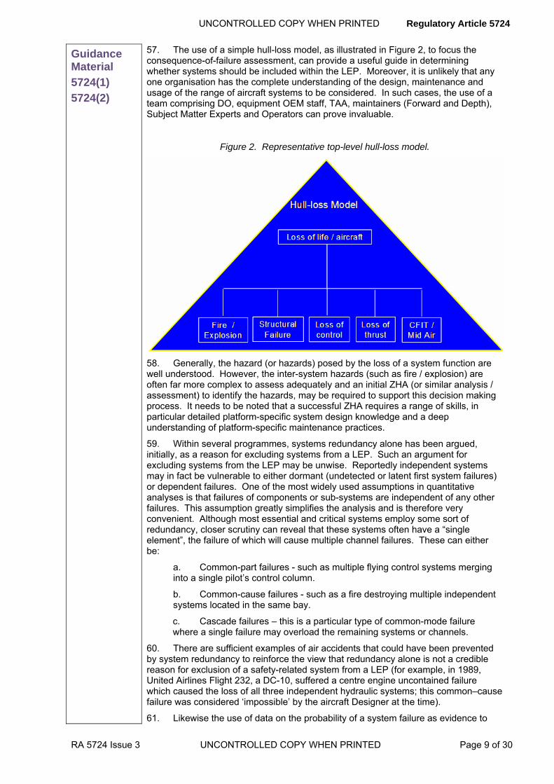
UNCONTROLLED COPY WHEN PRINTED Regulatory Article 5724
RA 5724 Issue 3 UNCONTROLLED COPY WHEN PRINTED Page 9 of 30
Guidance Material
5724(1)
5724(2)
57. The use of a simple hull-loss model, as illustrated in Figure 2, to focus the consequence-of-failure assessment, can provide a useful guide in determining whether systems should be included within the LEP. Moreover, it is unlikely that any one organisation has the complete understanding of the design, maintenance and usage of the range of aircraft systems to be considered. In such cases, the use of a team comprising DO, equipment OEM staff, TAA, maintainers (Forward and Depth), Subject Matter Experts and Operators can prove invaluable.
Figure 2. Representative top-level hull-loss model.
58. Generally, the hazard (or hazards) posed by the loss of a system function are well understood. However, the inter-system hazards (such as fire / explosion) are often far more complex to assess adequately and an initial ZHA (or similar analysis / assessment) to identify the hazards, may be required to support this decision making process. It needs to be noted that a successful ZHA requires a range of skills, in particular detailed platform-specific system design knowledge and a deep understanding of platform-specific maintenance practices.
59. Within several programmes, systems redundancy alone has been argued, initially, as a reason for excluding systems from a LEP. Such an argument for excluding systems from the LEP may be unwise. Reportedly independent systems may in fact be vulnerable to either dormant (undetected or latent first system failures) or dependent failures. One of the most widely used assumptions in quantitative analyses is that failures of components or sub-systems are independent of any other failures. This assumption greatly simplifies the analysis and is therefore very convenient. Although most essential and critical systems employ some sort of redundancy, closer scrutiny can reveal that these systems often have a “single element”, the failure of which will cause multiple channel failures. These can either be:
a. Common-part failures - such as multiple flying control systems merging into a single pilot’s control column.
b. Common-cause failures - such as a fire destroying multiple independent systems located in the same bay.
c. Cascade failures – this is a particular type of common-mode failure where a single failure may overload the remaining systems or channels.
60. There are sufficient examples of air accidents that could have been prevented by system redundancy to reinforce the view that redundancy alone is not a credible reason for exclusion of a safety-related system from a LEP (for example, in 1989, United Airlines Flight 232, a DC-10, suffered a centre engine uncontained failure which caused the loss of all three independent hydraulic systems; this common–cause failure was considered ‘impossible’ by the aircraft Designer at the time).
61. Likewise the use of data on the probability of a system failure as evidence to

Regulatory Article 5724 UNCONTROLLED COPY WHEN PRINTED
Page 10 of 30 UNCONTROLLED COPY WHEN PRINTED RA 5724 Issue 3
Guidance Material
5724(1)
5724(2)
exclude a system from LEP may be equally unwise. Design failure probability data are limited by lack of exposure to the real-world environment and in-service failure data are notoriously inaccurate. Additionally, the future failure probability rate cannot be assumed to be the same as the historical rate, as the system may well be entering a wear-out phase in its life. Without evidence to support the assumption of a relatively constant failure rate during the LEP period, such an argument may be ill advised.
62. Once the systems to be considered within the LEP have been identified, the individual components within that system will need to be considered, using a similar process, to identify those components that need to be addressed.
Identification of Propulsion LEP Components
63. The propulsion system is defined as the source of propulsive effort for the air vehicle. For fixed-wing aircraft it will include the aero-engine, modules, components and accessories and usually a similar management approach is applied to auxiliary power units, gas turbine starters and gas generators.
64. For propulsion systems, components for LEP are likely to be critical propulsion components (Group A) or sensitive propulsion components (Group B). These are usually identified by FMECA/FTA/Failure Hazard Analysis (FHA) (or similar techniques) during the design process. These components are those whose failure could cause a hazardous event or a safety issue. In addition, information from in-service Reliability Centred Maintenance (RCM) analysis and component failures may identify additional components for consideration within the LEP.
65. As with structures and systems a review of all propulsion components, undertaken by the OEM, TAA, maintainers (Forward and Depth) and SME, to identify those that should be considered for LEP can prove invaluable.
System Interfaces
66. The interfaces between disciplines, systems and components need to be considered carefully within a LEP and ownership clearly identified. It is largely immaterial whether interface components, such as oxygen bottle attachments or engine mounts are considered within the structure, systems or propulsion areas, as long as they are considered for inclusion within the LEP. The issue of interfaces is often further complicated by components being managed by different TAA and being supplied by different OEM. Therefore, this is a clear risk area within the LEP that may require careful management.
Components Excluded From The LEP
67. Once systems or components are excluded from the LEP it is unlikely that this decision will be reviewed unless an incident or accident occurs in service. Therefore, it is important that the rationale behind the risk-based decision to exclude a system or component from the LEP is well documented. Invariably, the risk-based exclusion would be based upon the low severity of the consequences of failure of the component, rather than a low probability of occurrence of that failure.
Categorisation of Life Extension Components
68. In the following sections, the likely key sources of information that could be used to support the LEP categorisation and provision of initial evidence to support the life extension requirements are described.
Design Data
69. The original design data will provide an invaluable insight into the potential to extend the life of components. Reviewed material may include documents such as the Statements of Design, Design Requirements and Design Standards. The aim of reviewing these documents is to understand the basis on which the component was designed, identify any relevant assumptions, such as loads, usage or environment, identify any dependencies such as maintenance actions and to identify whether there is likely to be life-extension potential for the component against the revised life requirement.
Qualification and Certification Evidence
70. The evidence presented in qualification and reviewed during certification can provide essential foundation information for a life extension. This will include the basis
UNCONTROLLED COPY WHEN PRINTED Regulatory Article 5724
RA 5724 Issue 3 UNCONTROLLED COPY WHEN PRINTED Page 11 of 30
Guidance Material
5724(1)
5724(2)
for any recommended limitations as well as providing an insight into potential areas where margins can be exploited or where increased risks may lie. For example, if qualification testing was conducted at higher loads than required or for a greater endurance than was necessary to demonstrate the design requirement, this information may be useful in assembling life-extension evidence. Also, particularly where components are used in a number of applications, the original design requirement may have been greater than required in service.
71. In some cases where original qualification and certification data are no longer available, the Design Standards applied at the time and evidence that the aircraft met the design requirements can be a valuable source of information for assessing the life extension potential.
Usage Information
72. Many of the assumptions included in the life clearance of aircraft components relate to the usage of the component in service. Moreover, the lives of the majority of components likely to be assessed within a LEP will be sensitive to changes in usage. The usage of aircraft invariably changes through the life of the fleet and this through-life usage needs to be considered within the LEP. These changes are often reflected in Concepts of Operation documents for example. In addition, the Statement of Operating Intent and Usage (SOIU), provides a good general indication of usage. Furthermore, previous issues of the SOIU are often retained within the document to provide some history.
73. Additionally, the significant difference between clearances and assumed usage needs to be understood in this context. For example, an aircraft may be cleared for high-temperature operations but it is likely that the design assumptions were predicated around operations in North-West Europe or the United States, for example, with occasional deployments elsewhere in the world. If this fleet were to be routinely deployed for long periods into a high-temperature and harsh environment, components that may be sensitive to environment changes may degrade at unexpectedly high rates (as has been seen with helicopter engines for example). In addition, these components may be subject to an ‘on-condition’ maintenance policy and signs of degradation may also be unlikely to be detected during a zonal inspection. The integrity of some elastomeric seals, for example, can be highly sensitive to repeated high-temperature excursions and these usage issues may need to be considered within the LEP.
74. Therefore, changes in usage, including the environment in which the aircraft is operated can have significant implications for life extension. The significance of the usage aspects may also need to be considered at various levels, relevant to the operation or environment seen by the LEP component. For example, structural damage has been identified on an aircraft type in the Auxiliary Power Unit (APU) bay. This damage, caused by prolonged heating of the structure, has been attributed to the APU routinely being run for around three times the assumed usage period, during operations. This mode of operations is not outside any limits but the implications for the structure and systems located in the APU bay could be significant and such issues need to be captured to ensure the LEP presents a complete analysis of the risks associated with life extension.
Concessions and Waivers
75. Concessions and waivers, which are used to record acceptable deviations from design, production or repair, have significant implications for LEP and have, without exception, proved to be problematic. When considering categorisation, the existence of concessions or waivers can affect the component category. Concessions or waivers could preclude life extension without further investigation or analysis, or the presence of widespread concessions or waivers may render life extension impractical. Moreover, the concessions or waivers may have been acceptable for the original life requirement but may not be acceptable, or there may be insufficient evidence to assess their acceptability for the life extension requirement.
76. Additionally, the lack of traceability of concessions and waivers has proven to be a significant issue for remedying issues exposed by the LEP reviews. In some programmes, trawling through many thousands of poorly-identified concessions and waivers has been a costly exercise. In one instance, the majority of the concessions

Regulatory Article 5724 UNCONTROLLED COPY WHEN PRINTED
Page 12 of 30 UNCONTROLLED COPY WHEN PRINTED RA 5724 Issue 3
Guidance Material
5724(1)
5724(2)
and waivers collated did not relate to the platform under LEP. This was because there was no platform identifier in the concession and waiver log. Consequently, all concessions and waivers raised during the production period for the platform had to be reviewed initially for applicability. Thereafter, tracing the applicable concessions and waivers, deemed to be unacceptable for life extension, to a particular component or batch of components was an extremely complex task. Tracing concessions or waivers invariably required some physical inspection of the aircraft to confirm or discount their presence. In some cases it was not possible to identify the concessions to individual aircraft or components and hence it was necessary to initiate precautionary and penalty remedial action across a number of aircraft within the fleet.
Repair and Overhaul
77. Repair and Overhaul (R&O) strip or condition reports, spares consumption and interviews with repair organisation staff can provide an invaluable insight into aspects that may need to be investigated further within a LEP. For example, many repair contracts are established using Inspect and Repair As Necessary (IRAN) principles and a report is usually assembled identifying the required repair action. In many cases, the information within this report is not collated or analysed in any way across the repair line. Simple analysis of data over time can be used to detect the onset of wear-out of systems components. Similar signs can be used to identify the onset of distress in structural components, such as an increase in corrosion or in fretting around rivets, loose fasteners or drop off in torque settings.
78. R&O staff may be well aware of signs of deterioration in the general condition and of specific issues for items returned for repair. However, individually these issues may not be significant enough for formal reporting action and hence they may not have been captured. A review of R&O findings and interviews with experienced R&O staff may well provide invaluable information to assess the categorisation of LEP components and to identify those issues that need to be addressed for the airworthiness of the platform during the life extension period.
Repair Instructions (Including RAP)
79. A review of repair instructions for both in-service application and for support organisations (such as repair facilities) can provide relevant information for LEP categorisation. Analysis of the number and extent of repairs embodied in particular components, or locations can indicate emerging issues in these areas. This is valuable for initial categorization of components and the further analysis of those components with the potential for life extension.
80. From a structural perspective, the underlying issues can be more complex to identify when general applicability (Topic 6) repairs have been developed and the repair instruction is no longer identified against particular aircraft within the fleet. However, this information can usually be collated either from maintenance records or from Unit Repair Teams, who typically maintain records of which aircraft have been repaired. Similar issues can be identified from repair information from systems or engine components.
81. From a LEP perspective, the aim of the review is, initially, to identify signs of degradation that could compromise the airworthiness of the fleet during the life extension period. For example, an occurrence of significant exfoliation corrosion on a wing rear spar was reported and repaired on an aircraft in an ageing fleet, under consideration for life extension. This occurrence was identified as a ‘one-off’ and no wider measures were invoked. However, analysis of the readily available records identified that this issue was endemic across the fleet but this had not been recognised appropriately in the continuing airworthiness measures.
82. Additionally, a repair review can identify where the current repair approach is likely to be ineffective for life extension. For example, repeated, enlarged repairs in the same area across the fleet can provide an indication that the repair approach is likely to be ineffective for life extension and either an alternative repair approach or modification may be the most appropriate method of assuring the long-term airworthiness of the fleet.
83. There have been several issues identified with repairs during LEP that are likely to have relevance to other programmes. In some cases, general applicability (Topic 6) repairs have been found to be inadequate for life extension, based primarily upon
UNCONTROLLED COPY WHEN PRINTED Regulatory Article 5724
RA 5724 Issue 3 UNCONTROLLED COPY WHEN PRINTED Page 13 of 30
Guidance Material
5724(1)
5724(2)
fatigue considerations. Moreover, repairs undertaken during previous ownership and repair schemes developed in-service, based upon an existing DO scheme, have also required remedial measures, such as inspection or replacement. It is commonplace for older structural repairs to have been designed statically with good fatigue practice, rather than with an accompanying fatigue analysis and this is basis for the RAP requirement in the AMC, see Military Aircraft Structures Airworthiness Advisory Group (MASAAG) Paper 106 Repair Assessment Programme.
Accident and Incident Reports
84. Accident and Incident reports are managed within the Failure Reporting, Analysis and Corrective Action System (FRACAS) used by each platform. However, there may be additional information within these reports that can be extremely relevant to LEP. Significant issues can become lost in time. Additionally, it is common for technical issues to occur in a cyclic nature, whereby measures introduced to address an issue become degraded over time as the impetus following an accident or incident becomes more distant. Moreover, trending of data over time by system, failure mechanism and even by individual aircraft can help provide an indication of issues and risks that could be considered within a LEP because the risk posed by these issues has the potential to increase as a result of life extension.
Fault reports
85. Fault reports are considered to include Serious Fault Signals (SFS), Narrative Fault Reports (F760), Unsatisfactory Feature Reports (F765) and Mandatory Fault Reporting Instruction (MFRI) reports; routine component replacements are considered later under maintenance data. Fault reports effectively provide the next step from accident and incident report in Heinrich’s Pyramid (see FAA System Safety Handbook, Chapter 16: Operational Safety in Aviation). Reported faults generally have the potential to become incidents; incidents have the potential to become accidents. Furthermore, it is rare for an accident attributed to technical cause not to have had previously reported related faults. In many cases either the significance of the reported faults was not fully appreciated or the corrective action was inadequate, with hindsight. Therefore, a review of fault reports to identify potential areas where risks may increase as a result of life extension, including reported faults where investigations were not undertaken, possibly due to proximity to OSD, can be extremely valuable within a LEP.
Maintenance Data
86. Maintenance is an essential element of continuing airworthiness assurance. However, the importance of maintenance as an airworthiness measure and the significance of extracting information from accurate maintenance data in the management of airworthiness may not have always been fully appreciated in the past (see the Haddon-Cave Nimrod Review). To undertake a successful LEP it is essential that the validity of the fleet maintenance data is understood. For example, if it is suspected that maintenance recording is often incomplete then using the lack of maintenance arisings to support an airworthiness decision within a LEP is likely to be wrong. Conversely, even if there are suspicions that the maintenance recording is often incomplete, identification of an issue to investigate further within the LEP, from the maintenance data, is likely still to be a valid decision.
87. Moreover, maintenance data, even when validated, can be misinterpreted because of how it is processed into information and these issues can be relevant for LEP. For example, failure rates and consumption rates are often viewed in average terms across the fleet, such as, mean time between failure (MTBF) or mean time to failure (MTTF) (for non repairable items). However, this can be a very coarse representation of information and may not be appropriate within a LEP. In some cases, failures with the same average rate may have completely different failure-time distributions and the shortest times to failure, or some low percentile of the population, may be far more significant for a safety-relevant item. Also, failures may not be randomly distributed around the fleet. There may be populations among the fleet and these failures may be concentrated in a small section of the fleet or even individual aircraft, due to differences in usage or variability between aircraft. Consequently, the risk for these aircraft could be significantly greater than the average would suggest and hence the representation of maintenance data may be significant in ensuring the

Regulatory Article 5724 UNCONTROLLED COPY WHEN PRINTED
Page 14 of 30 UNCONTROLLED COPY WHEN PRINTED RA 5724 Issue 3
Guidance Material
5724(1)
5724(2)
correct information is gained from the data.
88. Despite the potential pitfalls of inadequate or incomplete data, a significant rise in failure rates of a particular component or system can be an indication that the system or component is entering the wear-out phase it its life and this may significantly influence the LEP action required. For example, replacement or modification may be a more appropriate solution than attempting to generate additional clearance evidence. In reality, when a variety of suitable options are available, cost and time are usually the deciding factors.
Technical Instructions
89. A review of the technical instructions (i.e. Servicing Instruction (SI), Special Technical Instruction (STI), Routine Technical Instruction (RTI), Urgent Technical Instruction (UTI) and Preliminary Warning Instruction (PWI)) raised during the life of an aircraft can provide an incisive view into issues that may require further attention within a LEP. As previously discussed, technical issues are often cyclic in nature and a review of the history of technical instructions by system or component over time can identify issues that have not been fully resolved and where the airworthiness risk during a life-extension period may be unacceptable. Also, it is not always apparent how much significant technical history can be lost over time and it is rare for individuals to have experience of the complete history of a platform undergoing life extension.
90. Repeated up-issues of technical instructions can indicate that the remedial measures are inadequate. Also periodic instructions addressing the same issue can indicate an incomplete solution. Being unable to trace significant technical instructions to either modification action or changes in process or procedure can provide a possible indication of an unresolved issue. These issues are often well known to tradesmen in depth organisations in particular.
91. The issue of previous history either being lost or its significance not being recognised was clearly illustrated with the fortuitous identification of widespread stress corrosion cracking in a fleet of ageing aircraft, which had been subject to a ‘creeping’ life extension over many years. The issue of stress corrosion cracking in the wing spar boom flanges had been well known in the past and extensive inspection and a subsequent life-time repair and refurbishment programmes had been undertaken. However, the fleet life had been extended well beyond the scope of the refurbishment programme and adequate remedial measures to manage this issue had not been introduced, despite this problem resulting in a fatal accident in this aircraft type, operated by another air force.
92. A complete formal review of the through-life technical instructions raised for the fleet may prevent such a significant issue being missed in the future. Full reviews of technical instructions, over the life of ageing fleets, conducted during LEP, have revealed significant issues that required further attention to ensure ongoing airworthiness.
93. Technical instructions, viewed alongside design and qualification data can also illustrate aspects of the design that were proven by service experience to be inadequate. For example, initial analysis of a major structural component during a LEP revealed that the test spectrum applied had demonstrated a fatigue life significantly beyond the initial clearance requirement for the fleet. However, in-service experience revealed a catalogue of significant corrosion issues on a high-strength component dating back nearly 20 years. Without remedial measures to address the corrosion issues, the integrity of this component could easily have been compromised by relying entirely on the design and qualification data to underwrite the life extension.
94. Moreover, there have been instances identified of modifications being embodied on aircraft using technical instructions. In some cases subsequent cover modification action was also not carried out due to restrictions imposed on cover modifications at the time of modification classification. While this approach may have been acceptable for the original life of the fleet, it may not be acceptable for life extension and a review of technical instructions may highlight similar issues that may require further investigation during the LEP.

UNCONTROLLED COPY WHEN PRINTED Regulatory Article 5724
RA 5724 Issue 3 UNCONTROLLED COPY WHEN PRINTED Page 15 of 30
Guidance Material
5724(1)
5724(2)
Modifications and Capability Enhancements
95. The modification history of a fleet, including service modifications, can provide information highly relevant to a LEP. It can indicate where components were found to be inadequate for their intended service usage. This may include fatigue performance, resilience to environmental or accidental degradation or an inability to perform their required function. Additionally, there may be similar components on the aircraft that have not been modified and may be at greater risk during life extension.
96. In addition, modifications recommended by the DO but not pursued or not classified, can provide useful information for possible life extension measures. The LEP requirement may make the modification option a more attractive method of assuring airworthiness in the longer term. The issues surrounding LEP modification baseline are discussed later.
97. It is not uncommon for modification action (including cover modifications) not be taken or to be cancelled in the latter years of the life of the fleet. This is not unexpected, given the time scales often involved in taking a modification from inception to fleet embodiment. The remedial action put in place may be suitable for the remaining original life of the fleet but may not be suitable for life extension. Moreover, loss of configuration control, caused in part by failure to embody cover modification, requires considerable concerted action to recover; success in achieving this recovery within LEP has been mixed. Therefore, a review of Modification Committee meetings can identify issues that require further investigation within a LEP.
98. It is rare for a MOD fleet to remain in service for its entire life without a number of enhancements being made to its capability, including those implemented in response to Urgent Operational Requirements (UOR). Investigations undertaken within LEP have found instances where long-term airworthiness aspects of these capability enhancements may not have been given adequate consideration. This was particularly noted when the enhancements were not applied across the entire fleet (fleets-within-fleets issues are discussed further in the next section). In some cases this may have been because the enhanced capability was not initially intended to be permanent, or that intended regularisation measures were subsequently cut from the ongoing programme. Irrespective of the reason for the lack of long-term consideration, it is clear that a review of capability enhancements and UOR to ensure the adequacy of continuing airworthiness measures may be necessary.
Fleets Within Fleets
99. The issue of fleets-with-fleets (various portions of the fleet being of differing capability standard) has plagued the day-to-day management of military platforms and the implications are equally relevant to LEP (the establishment of a baseline modification standard for LEP is addressed later in this GM). The fleets-within-fleets issue has been highlighted as a major impediment in several LEP. In one programme (see KILSHAW, M. J., The Hawk Life Extension Programme, Air Clues Logistic Support Article, AW.Wk36/13, 1996.), a significant role-fit change programme was initiated in an attempt to alleviate the issue, with some limited success but measures such as these need to be taken early enough in the fleet’s life to have a significant effect.
100. Across several LEP there has been an unrealistic optimism in the ability to manage the consumption of life across the fleet to meet the life limits. This has usually been because the dominant driving factors that caused the fleet-within-fleets issue are usually still prevalent and life management is secondary to operational requirements. Therefore, where fleet management measures are going to be invoked to manage a fleets-within-fleets issue, these measures need to be introduced early in the life of the fleet to allow them to be effective and their success in meeting the alleviation requirement needs to be monitored.
Scheduled Maintenance Reviews and Extensions
101. The MOD policy is that the preferred method for developing maintenance schedules is using a RCM approach, based upon the Maintenance Steering Group 3 (MSG) standard and detailed in the JAP(D)100C-22. Historically, maintenance schedule reviews have generally been undertaken every 5-7 years but the periodicity of schedule review is now decided by the TAA.

Regulatory Article 5724 UNCONTROLLED COPY WHEN PRINTED
Page 16 of 30 UNCONTROLLED COPY WHEN PRINTED RA 5724 Issue 3
Guidance Material
5724(1)
5724(2)
102. From a LEP perspective, the information used to establish and develop the maintenance schedule through life can be very useful in identifying potential increases in risk with life extension. However, the basis of the maintenance schedules can also be variable across the fleets. Ideally, the process will have included risk-based identification of the SSI and Functionally Significant Items (FSI), (or Maintenance Significant Items (MSI) in some variations of the process). Thereafter, assessment will have been undertaken of the failure mechanisms, and vulnerability to Environmental Deterioration (ED) and Accidental Damage (AD), within a zonal and surface area analysis. However, some maintenance schedules have not been developed with this level of rigour and in many cases the MSG-3-based standard has been partially applied.
103. Understanding the basis of development of the maintenance schedule is important, irrespective of the approach taken, as this provides a clear indicator of the safety-related information likely to be available for the platform.
104. A schedule review will usually be undertaken as part of the LEP to ensure that all the issues raised during the programme are adequately incorporated into the maintenance schedules. However, as already discussed, it is also necessary to understand the maintenance schedule review history of the platform at the outset of the LEP. It is common for maintenance schedule reviews to be delayed or suspended as an aircraft approached its OSD. The implications of this action can be accentuated significantly when ‘creeping’ life extension occurs and the original decision to delay or suspend the schedule review is not revisited. Additionally, this situation can result in a drop off in the raising of unsatisfactory feature reports (F765) because tradesmen become aware that the management of the maintenance schedules has been minimised.
105. Also, the airworthiness assurance provided by a well-conducted MSG-based maintenance schedule review can be limited by constraints or exclusions applied to the process to reduce their cost and time scales. Moreover, recommendations from previous schedule reviews, where they have been undertaken, may not have been accepted by the TAA or their predecessors and these decisions need to be understood.
106. All these actions may have been acceptable within the original life requirement for the fleet but for life extension, knowledge of this history is required and the implications of these measures needs to be understood within the LEP context. This is necessary to ensure that remedial measures are introduced where required to combat any increase in the level of risk during life extension.
107. Additionally, throughout the life of most military fleets, there is a drive to extend the period of the scheduled maintenance cycle (i.e. the major cycle), to increase availability and to reduce cost of ownership. It is not atypical for the maintenance cycle period to double over the life of the fleet. In some cases, this extension may have been built upon sound foundations, using in-service experience from validated maintenance data to support a thorough RCM-based analysis. In other cases it may have been driven by a high-level requirement.
108. The implications of these changes to the maintenance cycle period, including the implications for increased latitude in maintenance extension (i.e. maintenance extensions are given as a percentage of the relevant cycle so a 25% extension could be twice the original latitude) need to be understood and the implications and any necessary rectification action need to be addressed within the LEP. This issue can be accentuated when the DO has limited visibility of the maintenance schedule and may not have been involved fully in the extension of the schedule during the service life.
Sampling and Forensic Examination
109. Sampling and Forensic Examination programmes (referred to as Age Exploration programmes in MSG-3) are initiated when a greater understanding of the vulnerability of a particular component is required. Although sampling programmes are not used as frequently as might be expected, if they have been developed, this information is relevant to LEP. It illustrates that further understanding of the vulnerability of a component was required and any results captured are likely to have direct implications for LEP.
110. For structures, the items that require sampling are identified in the Topic 5V.

UNCONTROLLED COPY WHEN PRINTED Regulatory Article 5724
RA 5724 Issue 3 UNCONTROLLED COPY WHEN PRINTED Page 17 of 30
Guidance Material
5724(1)
5724(2)
However, details of the actual structural sampling undertaken may have to be extracted from a range of documents including Structural Integrity Working Group (SIWG) minutes.
Ageing Aircraft Programmes
111. Ageing Aircraft Audits (AAA) have been carried out on MOD fleets since the early 1990s. Initially, these audits were focussed solely on structural issues but the remit of the audit has since been widened to include systems and propulsion aspects. The content of the AAA has evolved considerably since its inception and hence it is likely that there will be a marked variation in the approach taken and the information available from an AAA, depending upon when it was completed and what aspects were included within the audit. Nevertheless, an AAA has potential to provide much valuable information in support of a LEP in both LEP component categorisation and in assembling evidence to support the life extension.
112. A review of the scope of the audit, recommendations made and remedial action taken could identify issues that may need to be considered further within the LEP. Issues relating to degradation of significant components are of particular relevance. Also, it would be unwise to assume that all recommendations made during an AAA have been implemented. In some cases reviews undertaken during second AAA (AAA are to be repeated every 10 years) have identified outstanding recommendations from the first audit.
OLM/ODR Programmes
113. OLM/ODR programmes are mandated for MOD registered fleets (with a 2* exception case requirement). Although some fleets do operate a continuous OLM/ODR, generally, these programmes are periodic. A review of previous OLM / ODR reports is likely to identify issues relevant to a LEP. For example, components that are more highly loaded or have a more severe usage than expected may be less likely to reach the life extension requirement than design data may suggest and this may affect their categorisation. Conversely, components that are more lightly loaded, or have less severe usage than expected, may be more likely to meet the life extension requirement than indicated by design.
Previous LEP-Related Studies
114. Any previous LEP studies are an obvious source of relevant information. Additionally, a review of the history of the platform may identify studies that were effectively LEP but may not have been formally identified as such. Historically, life extension was often seen entirely as a structural fatigue issue and programmes that did not address increases in metrics seen as fatigue related (e.g. fatigue index (FI) for many fixed wing aircraft) may not have been clearly identified as life extensions.
Safety Panels, Integrity Working Groups, Committees, Strategies and Plans
115. There is a plethora of safety panels, integrity working groups and committees that have, over the life of a fleet, been used to manage the structures, systems and propulsion integrity aspects of the platform. A review of the minutes or output from these groups can provide valuable information to support a LEP. It is not always clear why decisions were made in the past and the minutes of these meetings are often the only record of the basis for airworthiness decisions and this can be highly relevant. The list of groups or committees will vary from platform to platform but is likely to include Platform Safety Groups, Integrity Working Groups (Structures, Systems and Propulsion), Type Airworthiness Meetings, Modification Committees, Local Technical and Faults Committees and Aircraft Environmental Damage Prevention and Control (EDPC) (formerly Corrosion Control Working Group). Additionally, in relatively recent years integrity plans and strategies have been developed and these may also contain information relevant to the LEP.
Other Operators’ Experience
116. Other operators of a type, or similar type, particularly those with older fleets than the MOD can often provide a useful insight into significant issues relevant to a LEP, and often assessment can be made of the effectiveness of any remedial measures applied. This is particularly relevant for United States-sourced aircraft, where the UK is unlikely to be the fleet-lead operator.

Regulatory Article 5724 UNCONTROLLED COPY WHEN PRINTED
Page 18 of 30 UNCONTROLLED COPY WHEN PRINTED RA 5724 Issue 3
Guidance Material
5724(1)
5724(2)
Obsolescence Studies
117. Obsolescence management is an increasing issue for MOD platforms and this has been recognised accordingly in the requirement for Obsolescence Management Strategies. From an LEP perspective, a review of Obsolescence Reports can provide a valuable collation of issues that are currently, or likely to become, significant for the platform. Many of these issues may not be visible within the day-to-day management of the platform as they may affect repair and overhaul facilities for example.
118. It is likely that a platform-specific obsolescence review may be required within a LEP to consider the existing obsolescence management (refer to JSP886, which should be considered AMC) and identify any gaps that may have airworthiness implications during the life extension. For platforms with an integrated industrial support arrangement, this may be routine business but there may be exclusions from this arrangement, such as Government Furnished Equipment (GFE). Also, many platforms in the inventory do not have the benefit of these integrated support arrangements.
Environmental Issues Studies
119. Environmental issues can have significant implications for life extension, in a similar fashion to obsolescence. Many of the substances traditionally used in aerospace are subject to increasing control and many are or will be prohibited in the future. In some cases these changes can have direct airworthiness implications, for example, the restrictions on chromate-based corrosion protection or the removal of lead-based solders. In other cases the issues may not be so well known, such as changes made to the chemical constituents of a fuel system elastomeric seal to remove carcinogenic substances.
120. A review of the Environmental Management Plan for the platform may be required within a LEP to consider the existing plans and identify any gaps that may have implications for continued airworthiness during the life extension period.
Spares Provisioning and Component Repair and Overhaul Programmes
121. It is common for supply provisioning and component repair and overhaul programmes to be significantly reduced or cut entirely during the latter years of an aircraft’s life. Such measures are taken to ensure that the necessary assets are managed in a cost-effective manner until OSD. However, these actions have had significant implications for LEP. Firstly, an acute shortage of assets has practical airworthiness implications. Shortages of spares can lead to a gradual erosion of standards, particularly where in-service limits are not well defined.
122. Recovering from the potential airworthiness implications of spares and repairs provisioning decisions made in the latter years of an aircraft’s life has proved to be a significant and ongoing challenge for LEP and spares shortages are a good indicator of an area requiring further investigation within the LEP.
Non-Extendable Components
123. In some cases it may not be feasible to extend the life of a component and this may be clear from an initial review of the original qualification evidence or from in-service experience. For example, the cleared life of a component may have been based upon test failure to a test spectrum that has been validated in service and an in-service inspection approach may not be considered adequately safe, due to critical crack sizes below detectable levels. In such conditions, there may be no practical measures that could be taken to extend the life of the component and alternative measures such as replacement or modification will usually be required.
Extendable Components
124. The list of components that can be extended without any further work is likely to be small. This approach is likely to require adequate qualification evidence for the required life extension in addition to validated in-service evidence, to corroborate the qualification assumptions and condition of the component.
Components Subject to LEP
125. It would be expected that the majority of components are likely to be categorised as having some potential for life extension but where the evidence is

UNCONTROLLED COPY WHEN PRINTED Regulatory Article 5724
RA 5724 Issue 3 UNCONTROLLED COPY WHEN PRINTED Page 19 of 30
Guidance Material
5724(1)
5724(2)
incomplete. In some cases this may prove not to be cost effective but this cannot usually be ascertained before further work is done to analyse the issues in greater detail. Guidance on the development of the LEP Qualification Programme Plan, to address the life extension evidence required, is detailed in the following section.
LEP Qualification Programme Plan
Background
126. The LEP QPP is the umbrella under which the various elements of the LEP component requalification evidence generation are conducted. In most cases it may require a combination of approaches to gain sufficient requalification evidence for a particular component, such as OLM/ODR to measure the usage in service and additional testing, using a validated usage spectrum, to demonstrate the components capability, supplemented by directed inspections. Some components may not meet the life extension requirement and hence it is usual to undertake a preliminary study of the more complex proposed LEP solutions to generate a degree of confidence in the likelihood of success in the proposed approach. The LEP Component QPP needs to include forecast time scales for the availability of additional QPP evidence, identification of key technical risks and contingency options for higher-risk approaches.
127. There is a wide range of approaches that can be taken to obtain the necessary requalification evidence and several of the more common methods used are described in the reminder of this section. Not surprisingly, many of the measures discussed below mirror the sources of data used to identify the LEP components and to understand their condition initially.
128. In addition to methods of obtaining clearance evidence, key issues identified in LEP to date are described and potential solutions are outlined.
Establishing the Clearance Evidence Basis
129. For each component within the LEP (determined by risk-basis on the consequences of failure), one of the first tasks is to understand the evidence basis for the clearance of that component and how this may be affected by life extension. At the simplest level, the evidence required to support a component LEP can be considered to be divided into four source areas: understanding the material properties (e.g. fatigue strength, corrosion resistance or thermal conductivity), understanding the effect of geometry (e.g. cut-outs, joint configuration, wire bend radii, insulation thickness), understanding the loads (e.g. gust, pressure, vibration, thermal, impact) and understanding the failure criteria (e.g. residual strength, system leak, loss of function, buckling), as illustrated in Figure 3. This simple diagram can be useful in assessing the completeness of evidence available to ensure all aspects are covered for a particular component.
Figure 3. Evidence areas for LEP
Evidence Sources
130. The qualification and certification of aircraft for LEP relies on a combination of test evidence, analytical evidence and service experience. Test evidence alone,

Regulatory Article 5724 UNCONTROLLED COPY WHEN PRINTED
Page 20 of 30 UNCONTROLLED COPY WHEN PRINTED RA 5724 Issue 3
Guidance Material
5724(1)
5724(2)
without analysis to confirm that the test is representative, backed up by in-service experience, is inadequate. Equally, analytical solutions, without test validation and in-service evidence, are also lacking. Therefore, although the following sections are divided into test, analytical and in-service experience topics, these aspects need to be considered as complementary, as illustrated in Figure 4.
Figure 4. Evidence sources for LEP.
Clearance Evidence From Existing Tests
131. The demonstrated clearance for the major load-bearing structure and for major systems and propulsion components in military aircraft is expected to be based upon testing, supported by analysis. The test specimens often range from near-complete aircraft to stand-alone tests of individual components. This approach is underpinned by a pyramid of test and analytical programmes from materials data upwards. Within the LEP, it may be necessary to revisit the test-based clearance for LEP components to identify whether further clearances can be supported from the original test evidence.
132. The use of OLM/ODR (discussed later in this section) or other sources of loads and usage data to review the test spectra, is the main potential source of additional clearance and this approach has been used successfully in a number of programmes.
133. Care needs to be taken to ensure that any limitations in the loads and usage data used for the comparison, or in the tests themselves, are understood. For example, a particular loading action may not be represented on the test (e.g. undercarriage side load on touchdown) but this loading action may be recorded in the loads and usage data. Also, major tests necessarily include compromises as they cannot always fully replicate the loading conditions and simplifications need to be made in the generation and application of balanced load cases. In addition, as is often the case for fixed-wing aircraft fatigue tests, high-cycle fatigue may have been represented by using an equivalent damage approach, with fewer low-frequency cycles of higher magnitude. The implications of these issues need to be understood in any approach to gain a greater clearance from existing test evidence.
134. There is no doubt that trying to gain a greater clearance from existing test evidence has its challenges and potential pitfalls. However, it has proven extremely valuable in gaining life extension clearances on many programmes.
Clearance Evidence From Supplementary Tests
135. In many cases, the testing undertaken during original qualification may not have fully demonstrated the ‘life’ capability of a LEP component (i.e. the component did not fail under test and was unlikely to do so). For structural components, for example, an initial view of features in this category can sometimes be gained from the FTR (RA5000 series), or equivalent documents. In many of these documents may identify a Fatigue Quality Factor (FQF) (or similar terminology). These provide an indication, from analysis, of what factor would have to be applied to the fatigue spectrum to generate a failure. Therefore a FQF of 1.2 suggests that the current fatigue spectrum would need to be increased by 20% to generate a failure. Although feature and load spectrum dependent, a first-order approximation suggests a 20% stress factor would

UNCONTROLLED COPY WHEN PRINTED Regulatory Article 5724
RA 5724 Issue 3 UNCONTROLLED COPY WHEN PRINTED Page 21 of 30
Guidance Material
5724(1)
5724(2)
represent a life factor of around 2. Therefore, where the fatigue spectrum was replicated on test, such a component may have significant undemonstrated fatigue life capability and could be a potential candidate for further testing.
136. For many structural, systems and propulsion components, indications of reserve capability of the component may not be readily available. However, where additional testing of components is a consideration, an initial analysis of the likely capability of the critical features in the component, under realistic loading spectra, can be a worthwhile investment. Conversely, careful consideration may be required before embarking on testing for components or features shown analytically to have little capability beyond the existing test-based clearance.
137. In anticipating likely life margins, it is also worthwhile to investigate the load cases that drive the design of the component. For example, from a structures / systems perspective, a flying control system may be designed to a jam load case. The loads generated by this case may be far in excess of the usual service loads in the systems and this may provide confidence that further life capability can be demonstrated in the components in the system designed against this load condition.
138. Additionally, it is not uncommon for a modification to a significant feature to be made and requalification undertaken by analysis, based upon the premise that the new feature was at least as good as the original feature. In such cases the full capability of the modified feature is usually not exploited unless further testing is undertaken.
139. Where test articles are still available, restarting or continuing test programmes is usually the most efficient method for gaining the additional clearance required. However, there is also a place for development of new tests. These have proven particularly valuable for LEP where inspection-based regimes are unlikely to be successful. For example, inspections may be impracticable for highly-loaded compact structures (as often found on combat aircraft) or where high-strength materials, with short critical crack lengths, are used (e.g. landing gear and gearboxes).
140. Using aircraft or components from service, where test articles are no longer available, can often provide an adequate solution. This approach has been used successfully on several LEP. However, care needs to be taken to understand the damage state of the ex-service test article and pre-emptive repairs may be required. Additionally, account needs to be taken of the in-service usage, although this is generally small compared to the additional testing requirement.
141. Several LEP have also used simplified tests, either using manufactured test articles or retired service structure or components, to add to the body of evidence in support of a clearance. These tests have been used, for example, where the spectrum can be simplified to a few (or one) dominant loading actions and represented on simple tests to illustrate the progression of damage through a structure. This can be particularly useful where the load redistribution and damage progression in a complex structure is difficult to predict analytically.
142. Alternatively, simple tests to represent known in-service occurrences, to understand their implication for LEP, such as misalignment of fuel pipes, or the effect on fatigue life of reductions in torque loading in a bolted joint, have proven invaluable on several programmes.
143. Materials and coupon tests can also provide invaluable and cost-effective information to support a LEP, where the existing data are inadequate.
144. Specific guidance related to structural Life Extension Fatigue Test (LEFT) can be found in Def Stan 00-970, Part 1/6, Section 3, Leaflet 37.
Clearance Evidence From Analytical Solutions
145. As has already been discussed, test-based and analytical solutions are interrelated within the design and clearance process. Moreover, a competent Design Organisation is likely to have an ongoing process of baselining its analytical tools to test results as part of its pyramid approach to design and qualification. Additionally, as previously discussed, modelling capability across a whole range of disciplines including structures, systems design and analysis, aerodynamics and loads has increased dramatically since many of the MOD’s aircraft fleets were designed and

Regulatory Article 5724 UNCONTROLLED COPY WHEN PRINTED
Page 22 of 30 UNCONTROLLED COPY WHEN PRINTED RA 5724 Issue 3
Guidance Material
5724(1)
5724(2)
hence advantage can be taken of these developments. These capabilities may also benefit from additional information, such a wind tunnel data, flight loads data and temperature and environmental surveys captured since the original design of the aircraft.
146. Modern mathematical tools, such as Finite Element Modelling (FEM) were in their infancy when many of the MOD’s fleets were being designed and hence the tools used in design were often far less precise than those used today. Hence, the application of more sophisticated analysis tools, when used by experienced practitioners, with appropriate validation (e.g. against OLM/ODR results, strain surveys from tests or keyed into test failures) can prove extremely useful within a LEP. Caution needs to be applied when taking advantage of more sophisticated analysis tools, that the precision in the analysis is matched by the precision in the manufacture and the in-service condition of the component in reality.
147. These tools can also prove extremely useful for analysing complex components where historically, the design assumptions for complex features may have been highly conservative to account for uncertainty in load and stress concentration interactions. In such cases, models, validated against test data, may provide evidence to support alleviations and potentially life extension. This approach has been used successfully in LEP.
Clearance by Inspection
148. Inspection, from visual to complex Non-Destructive Inspection (NDI) is one of the foundation stones of a continuing airworthiness programme for structures, systems and propulsion components. Consequently, LEP have relied heavily upon inspections as a way of mitigating the risk of failure of components. Where alleviation from spectra review, test evidence, additional testing and analytical approaches are unable to generate a life extension clearance, an inspection-based approach is often considered.
149. However, it is important to ensure that an inspection programme has adequate foundations. The inspection has to be practicable and adequate access needs to be available to undertake the inspection with confidence. Where inspections are used to mitigate failures, there has to be perceptible signs of distress that correlate with the expected failure mechanisms and that can reasonably be expected to be identified under in-service conditions. There also needs to be a suitable level of confidence that detection will occur before the integrity of the component is in question. Where limits are applied to inspections these need to be measurable and the limit values need to be readily accessible to those undertaking the inspections. Inspection regimes also need to be supported by a test-evidence based approach to ensure damage nucleation and propagation are adequately understood.
150. Although inspections may, at first sight, appear to be the most cost-effective solution to LEP, this may not always be the case. As has already been discussed, for highly-loaded compact structure and high-strength material, an inspection-based approach may not be supportable for either access or short critical crack length reasons. Moreover, without sufficient investment in test and analysis to support the inspection-based approach, a highly conservative approach may be necessary. Hence, inspection thresholds and repeat inspection periods tend to be extremely short, with a significant burden on the front line. Additionally, safe-life aircraft structures, for example, were often not designed to be inspected and in many cases significant damage has been introduced into aircraft while undertaking inspections. For example, repeated removal of fin and tailplane attachment bolts for NDI has introduced mechanical damage on several aircraft types.
151. For a certified clearance-by-inspection it is necessary to understand:
a. The detectable damage size (e.g. crack), with a defined level of confidence.
b. The damage growth rate and direction of growth in the materials and features present, under a representative load spectrum.
c. The failure criteria.
152. For damage tolerant designed structure, this information should be part of the design and qualification process and the crack-free period should have been

UNCONTROLLED COPY WHEN PRINTED Regulatory Article 5724
RA 5724 Issue 3 UNCONTROLLED COPY WHEN PRINTED Page 23 of 30
Guidance Material
5724(1)
5724(2)
demonstrated by a full-scale fatigue test. However, for safe-life designed structure and for many systems and propulsion components, it is unlikely that this information is readily available and hence this may need to be generated to support a directed inspection-based clearance (zonal inspections are not considered adequate to support inspection-based clearances).
153. Inspection is also the primary method for detecting corrosion. Corrosion, with the potential for corrosion-fatigue interaction, is one of the key threats to aircraft during life extended periods and corrosion development is notoriously difficult to predict analytically with any accurately. For well-designed aircraft with a good choice of materials and barrier systems, corrosion will often occur at locations where the barrier system has been breached by mechanical damage and detection will be highly reliant upon inspection regimes and effective remedial action.
Usage monitoring (including Manual Data Recording Exercises (MDRE))
154. Usage monitoring can be important for two aspects of LEP clearances. Firstly, as already discussed, it can be used as a method of gaining an understanding of how a component is used in service. Secondly, the introduction of additional usage monitoring can be used to reduce the safety factors applied to a component life during the life-extension period, if the dominant loading actions can be monitored on a fleet-wide basis.
155. From the perspective of understanding the usage in service, it is rare for all the available usage information available on a platform to be fully exploited. This is increasingly prevalent in more modern aircraft, which usually have onboard monitoring systems or have the capability to capture onboard data relatively easily. Therefore, it may be extremely useful to review the data available against the LEP component usage assumption to identify those aspects that can be validated from the existing data set.
156. In some cases, it may be adequate to supplement the available data with MDRE. These are more usually undertaken on rotary-wing aircraft where a manual recording of parameters such as flight conditions, rotor start and stop and air-ground-air cycles is undertaken. Also, a similar manual flight condition recording is used as the main aircraft usage monitor on some large military fixed-wing aircraft. Such programmes can offer a cost effective and rapid solution and can be particularly useful in identifying events or conditions that are difficult to define deterministically from existing aircraft data.
157. The introduction or development of a monitor to reduce the required safety factors on usage to gain the required life-extension clearance has been considered on several LEP. In reality the decision is usually made on economic grounds rather than airworthiness considerations. Often the main impediment is that the life remaining is too short to allow the reduced lifing factor to provide sufficient margin (i.e. the decision is effectively too late). Nevertheless, in some cases the adaptation of an existing monitor to capture the main loading actions of an additional feature may be appropriate, once validated. For example, OLM/ODR data may show an adequate correlation between store attachment fatigue and flight parameters already captured within the aircraft monitoring system (such as normal acceleration and roll rate). In such cases the introduction of an additional, validated, algorithm for stores attachment monitoring may be appropriate, as long as the overall fatigue substantiation process for the potential monitor location is understood.
158. Helicopter Health and Usage Monitoring Systems (HUMS) are now widely fitted across MOD fleets. These systems often capture a great many flight parameters but in many cases much of the captured data is not used to support continuing airworthiness. However, a discrete exercise to use these data to support LEP could provide invaluable information to understand in-service usage.
159. It is also important to recognise that in-service usage may have changed significantly during the life of the fleet and this may need to be included in any lifing assessments.
Operational Loads Monitoring (OLM)/Operational Data Recording (ODR)
160. OLM/ODR is effectively the next step in understanding usage, when adequate information cannot be obtained from existing data; OLM/ODR has proven invaluable in
Regulatory Article 5724 UNCONTROLLED COPY WHEN PRINTED
Page 24 of 30 UNCONTROLLED COPY WHEN PRINTED RA 5724 Issue 3
Guidance Material
5724(1)
5724(2)
several LEP. Many of the revised clearances provided could not have been achieved practicably without usage spectra derived from OLM/ODR data, as has already been discussed. Traditionally, OLM/ODR have been primarily focussed on validation of structural loads or usage. However, understanding the loads and usage is equally applicable to life extension of systems and propulsion components. For example, airbrake deployment data was used on one LEP to support the life extension of the airbrake jack. There is certainly room for this integrated approach to be developed further, particularly within the fixed-wing aircraft where there is often unnecessary segregation in data capture between structures, systems and propulsion disciplines.
161. Guidance on the conduct of OLM programmes is provided in MASAAG Paper 109 and many of the principles identified are equally applicable to ODR programmes. Central to the guidance is the establishment of clear requirements at the outset. If there is an ongoing OLM/ODR capability in the fleet, then this can usually be modified to meet the requirements of the LEP. If there is no OLM/ODR capability in the fleet, it may take several years before useful information can be obtained from the programme and hence it is prudent to initiate an OLM/ODR programme as soon as possible to support the LEP.
Directed Surveys
162. LEP have shown the importance of using on-aircraft and off-aircraft directed surveys (e.g. hydraulic components undergoing bay maintenance) and interviews with key personnel to validate the primary assumptions made within the programme. A LEP needs to be based upon reality rather than the assumption of reality and there may be issues that affect the LEP that are not apparent from documentation or where their significance has not been identified.
163. Involving experienced tradesmen, particularly those undertaking deeper maintenance on and off-aircraft is an invaluable exercise within a directed survey. For example, it was identified during one LEP directed survey that lifed major sub-components were regularly moved from one component to another while undergoing a bearing replacement procedure during maintenance. The primary component had an ERC but because the sub component had no unique identification number there was no record of these changes. This component was required to undergo life extension and it had been previously assumed that the component parts remained together.
Sampling or Forensic Examination
164. Sampling or teardown programmes have been used as a primary tool in structures and systems LEP for many years. They are also used widely to validate life predictions on critical propulsion components.
165. Structural sampling / teardown was traditionally focussed primarily on identifying areas of corrosion, particularly in hidden structures. The design assumptions are made assuming un-corroded samples and there are no allowances made in the design codes for the occurrence of corrosion in aircraft structures. Barrier systems (e.g. surface finish) are specified and qualified in design and it is assumed that these barrier systems are maintained in service. It is also assumed that corrosion in service is detected, corroded material is removed by blending or polishing and the barrier system is restored. Thereafter, the long-term effect of the corrosion is considered to be as a consequence of the material removed, rather than a stress concentration at the bottom of a corrosion pit, for example. The evidence from sampling and teardown programmes, as well as service maintenance data, is essential to identify hidden corrosion issues, or corrosion issues that have not been dealt with adequately, either of which could call into question the life extension certification for the fleet. Improved corrosion control and recovery actions are among those likely to be included in enhanced continuing airworthiness measures, identified during a LEP.
166. In recent years, the remit of structural sampling / teardown has been widened to include detection of fatigue damage (including WFD), particularly when aircraft have exceeded their safe lives or where there is limited confidence in the SI assurance evidence for the fleet (such as fatigue test limitations). Detailed guidance on the conduct of structural sampling / teardown can be found in MASAAG Paper 105 and details of potential structural sampling areas, based upon SSI, are detailed in the Topic 5V.
167. Sampling has also been used to support a wide range of systems LEP from
UNCONTROLLED COPY WHEN PRINTED Regulatory Article 5724
RA 5724 Issue 3 UNCONTROLLED COPY WHEN PRINTED Page 25 of 30
Guidance Material
5724(1)
5724(2)
hydraulic components, flying control cables to electrical wiring looms; in each case valuable evidence has been assembled during these programmes. For many components, sampling is the primary method for gaining a detailed understanding of the condition of the component in service and this is essential for the LEP to retain its validity. For example, for many aircraft types there are known areas where aircraft wiring is subject to adverse conditions and hence potential degradation, such as swamp areas and areas in close proximity to engines, hot air systems, hydraulic systems and fuel systems. It is not always apparent from visual inspection whether the integrity of wiring insulation has been compromised. Sampling and testing of electrical wiring, against original specifications, can provide essential information either to support the LEP clearances or to identify the need for remedial action.
168. In addition, a sampling programme undertaken with an AAA highlighted issues with flying control bearings being identified as ‘sealed for life’, which had been taken to mean a maintenance-free life; however, no associated life had been identified for the bearings. Further investigation identified that these were low-maintenance bearings rather than maintenance-free and control restrictions on several other aircraft types, operated in civil aviation, had been attributed to failure of similar bearings.
169. A key issue for sampling / teardown programmes is to ensure that they are well focused and address all the requirements. Also, it is rare that one organisation fully appreciates all of the skills or holds all the knowledge necessary to undertake a successful sampling / teardown programme and hence involvement of DO, TAA, SME and maintainers (forward and depth) has proven extremely valuable in previous sampling programmes.
Maintenance Actions (e.g. Lubrication)
170. The introduction or adjustment of maintenance actions, such as reapplication of existing or improved protective or barrier coatings, lubrication or torque adjustment can be valuable tools within a LEP. Although it is impossible to prevent entirely the degradation of materials, the pace of this degradation can, in many cases, be dramatically reduced by maintenance actions.
171. Although it would be expected that most feasible maintenance actions may have already been included in the maintenance schedule, using an RCM-approach, this may not be the case, particularly where the maintenance schedule has had limited RCM analysis or has not been amended for some time. For example, failure mechanisms that could be alleviated by maintenance actions may be apparent in service and these mechanisms may not have been anticipated during the maintenance schedule development or subsequent reviews.
172. The widespread corrosion found (see Systems Airworthiness Advisory Group (SAAG) Paper 001 - Lessons identified from initial Ageing Aircraft Systems Audits and Condition Survey Programmes) on aircraft systems components during AAA and Condition Surveys (CS) suggests that there are improvements that could be made using relatively simple maintenance actions and LEP may be an opportune time to implement such changes within the continuing airworthiness programme.
Modification
173. Where a life extension cannot be demonstrated for a component and there are no valid maintenance actions or inspections that could be used to support the revised clearance, modification action may be an appropriate method for assuring airworthiness. Where these options have been considered in LEP, the modification proposal had often already been developed prior to the LEP but had not been either classified or embodied.
174. Also, where the life extension period is sufficient, it is often valuable to review potential modifications to LEP components on a cost-of-ownership basis.
175. Additionally, there is now a wide range of fatigue enhancement measures that can be used to improve the fatigue performance of structures, systems and propulsion components. These include: cold working of holes with and without interference fasteners, shot peening and laser peening, shape re-profiling and material deposition methods. Several of these processes are now used routinely in new aircraft designs and some have been applied retrospectively as fatigue enhancement measure on

Regulatory Article 5724 UNCONTROLLED COPY WHEN PRINTED
Page 26 of 30 UNCONTROLLED COPY WHEN PRINTED RA 5724 Issue 3
Guidance Material
5724(1)
5724(2)
MOD platforms.
176. In the right location, and with confidence that the technique can be applied consistently, several of these fatigue enhancement measures are attractive options for life extension. However, the fatigue life improvements demonstrated by these approaches can be sensitive to the load level and the applied spectrum (e.g. constant amplitude or variable / spectrum loading). Therefore, representative test data are necessary to allow certification of these methods in LEP.
Replacement
177. Replacement of items that are not adequate for life extension, with components to the same standard is an option that has been used widely in LEP.
MFRI
178. Mandatory Fault Reporting Instructions (MFRI) can be a valuable tool when it is necessary to gain a greater understanding of the issues affecting a particular component during or after a LEP, particularly where there is reduced confidence in the maintenance data for that component.
Concessions
179. Identifying concession, locating them in-service and providing evidence that they adequate for the life extension period has proven extremely challenging for a number of LEP and is likely to be an issue for most programmes.
180. From an airworthiness regulation perspective, the issues are relatively simple – the concessions need to be shown to be adequate for the life extension period. The challenge for a LEP is to produce a solution that is realistic and affordable. For larger fleets there may be many thousands of concessions with little or no traceability to aircraft tail numbers or major components. These concessions may have been assessed against the original design requirements for the platform but may not be adequate for the LEP requirement and evidence from LEP has shown this to be the case.
181. A successful approach adopted within a LEP was to subject the concessions to a staged filtering process to reduce the task to a more manageable size, without compromising integrity. For example, concessions not applicable to the MOD fleet were removed and concessions on fixed structure on Category 5 aircraft were also removed. Thereafter, a staged analysis approach was undertaken whereby concessions that clearly met the LEP requirement, using conservative assessment methods were identified and cleared and those remaining were subject to progressively more in-depth analysis.
182. Where clear evidence of the fatigue life of the concession was not available, approaches such clearance by comparison with more highly stressed features on the structure or component were used (e.g. a blended machining error or local thinning could often be passed by comparison against nearby attachment holes). For those concessions that could not be cleared by this approach, a more detailed analysis was undertaken. This included the development of individual fatigue spectra, limited FEM (for assessment of complex stress concentrations or local loading effects) and simple coupon testing.
183. This approach was also supplemented by technical instructions to identify those concessions in service with visible cues. Detailed analysis of often incomplete service maintenance records was also undertaken to identify possible locations for unidentified concessions. In many cases, this allowed the risk to be ring-fenced down to a manageable number of aircraft where remedial actions, such as inspections or component replacements were undertaken.
Tracking of lifed items
184. Lifed items are tracked using either ERC or equivalent systems. Engineering Record Cards (ERC), in this context refers to all component manual and electronic records which identify the modification status, application of instructions, repairs and usage. LEP have identified significant issues with decisions made at introduction to service as to which components will have ERC. In several cases, significant, interchangeable components, with fatigue life limits, were found to have been introduced into service without ERC. Consequently, it was extremely difficult to

UNCONTROLLED COPY WHEN PRINTED Regulatory Article 5724
RA 5724 Issue 3 UNCONTROLLED COPY WHEN PRINTED Page 27 of 30
Guidance Material
5724(1)
5724(2)
identify life consumed and modification status of these components with any confidence and in many cases penalty life values had to be implemented to assure airworthiness.
185. The default position has often been to assume fleet leader values; however, with persistence a more realistic approach can usually be developed using a combination of validated maintenance data (even when incomplete), repair records, previous technical instructions (where component serial numbers are often identified), modification histories and accepted statistical methods. In several cases this more complex approach (as opposed to assuming fleet leader data) has prevented the effective grounding of large proportions of the aircraft fleet undergoing LEP.
186. Following a LEP, it has generally been necessary to increase significantly the number of components that are subject to life tracking, using appropriate metrics (e.g. flying hours, FI, landings, cycles, starts, deployments etc).
LEP Baseline Modification Standards
187. The maintenance of configuration control is a particularly challenging aspect of day-to-day airworthiness management. However, the complexity of this issue increases significantly with the advent of a LEP. Firstly, it is necessary to understand the modification status of the aircraft to be subject to life extension. In some cases it may be necessary to establish several baseline modification standards; this may be the case when aircraft were introduced to service in blocks or tranches or when fleets-within-fleets issues are prevalent (as previously discussed). Experience has shown this not to be a trivial exercise, particularly when considering aircraft equipment, role equipment, and commodity item modification standards, as well as aircraft modification standards.
188. Additionally, modifications not considered of direct airworthiness significance at classification (i.e. below B2 classification), may not have been actively managed within the fleet and the fleet modification status for below B2 class modifications may not be clear. Embodiment of the B2 and below classified modifications may, in some cases, be essential because the pre-modification standard has been shown to be inadequate to meet the life extension requirement. Hence it may be necessary to verify the modification status of the fleet and implement appropriate management of these modifications thereafter.
189. This issue can be further complicated where equipment modifications have not been subject to cover modification action. In such cases it may not be possible to identify the modification status of the fleet or off-aircraft assets, without physical inspection. As previously discussed, in the extreme, component modifications may have been introduced under technical instruction. Further complications arise where the component modified is interchangeable and the technical instruction has been recorded against the aircraft, rather than the component. In such cases there may well be no alternative to a visual inspection of the fleet and off-aircraft assets to identify their modification status, where this is possible.
190. Even in programmes where the documentary evidence suggests that the management of modification standards within the fleet is adequate, it has proven invaluable to undertake physical checks of the airworthiness-significant modification state, to validate these assumptions. In some cases, significant airworthiness modifications, identified as fleet embodied and hence within the LEP baseline modification standard, were found not to have embodied on several aircraft within the fleet. In particular, the configuration of early production run aircraft, or pre-production aircraft, as they have been termed in some fleets, is a potential area for investigation.
Widespread Fatigue Damage Assessment
191. Widespread Fatigue Damage (WFD) is the simultaneous presence of cracks at multiple structural locations that are of sufficient size and density such that the structure will no longer meet the residual strength requirements. The likelihood of WFD in aircraft structure increases with usage. WFD results from many cracks that are generally too small to be reliably detected using existing inspection methods. These cracks could grow together more rapidly than might be expected, so that failure could occur before another inspection is performed to detect them. The simultaneous presence of fatigue cracks that may grow together, with or without other damage in
Regulatory Article 5724 UNCONTROLLED COPY WHEN PRINTED
Page 28 of 30 UNCONTROLLED COPY WHEN PRINTED RA 5724 Issue 3
Guidance Material
5724(1)
5724(2)
the same structural element, such as a large skin panel, is known as Multiple Site Damage (MSD). The simultaneous presence of fatigue cracks in similar adjacent structural elements, such as frames and stringers, is known as Multiple Element Damage (MED). Some structural elements can be susceptible to both types of damage, which potentially could occur at the same time. If undetected, either type of damage could lead to catastrophic failure due to reduction of the strength capability of the structure.
192. The risk of WFD has now been recognised by the civil regulatory authorities as the limiting structural factor in continued operations of damage-tolerant large aircraft and there will increasingly be requirements to establish an effective Limit of Validity (LoV) beyond which the aircraft will not be operated.
193. However, the risk of WFD is not restricted to large airliners and is equally likely in any regions where similar features are subject to similar stress levels and hence there is a need to assess the structure of an aircraft for its potential vulnerability to WFD and then to take appropriate remedial action. GM on WFD can be found in MASAAG Paper 116.
‘On-condition’ components
194. A large proportion of aircraft system components are maintained in service using ‘on-condition’ criteria, with no published ‘hard’ lives. This has proven to be a key issues in systems life extension, where it has not always been appreciated that the clearance for components to remain in service using an ‘on-condition’ approach is still bounded by the demonstrated original design qualified and certified life limits.
195. Therefore, where these components are deemed to be safety critical, safety related or safety relevant (a range of terminologies are generally in use), the ‘on-condition’ approach needs to be requalified and recertified for the life extension period. Basically, the continued function and reliability of the component needs to be demonstrated for the life extension period to ensure that the component is not entering a wear-out period, as was discussed earlier in this GM. Also, the addition of evidence from service experience is an essential element of the analysis. It is not uncommon for in-service experience to indicate significant shortfalls in the validity of the original qualification and certification. For example, the ‘on-condition’ approach may have been based upon design MTBF rates which have proven in service to be extremely optimistic.
Commodity Aspects
196. LEP have highlighted how many components used on a platform are managed outside of the direct control of the platform TAA. In previous LEP there have been a number of breakdowns in communications and lack of understanding between the agencies involved in managing this vast range of assets. This is an area that may require considerable attention within a LEP to ensure that airworthiness-related issues are adequately addressed for all safety-relevant components fitted to the aircraft, irrespective of how they are managed.
197. Therefore, it is essential that the platform TAA, commodity Project Team (PT), DO and commodity DO/OEM understand the aims and approach to be taken within the LEP and are supportive of the programme. Commodity PT may also have to consider the implications of the LEP for multi-user items.
Condition Survey
198. A Condition Survey (CS) of a representative sample of fleet-leader aircraft can be an invaluable tool in validating the LEP assumptions, particularly those on aircraft condition. Corrosion, for example, has been identified as one of the key threats to integrity within a LEP. A CS programme can be used to validate assumptions that corrosion areas have been identified and addressed. Additionally, CS can be used to highlight cumulative airworthiness issues that may become significant during the life-extended period and may not have been initially recognised or may have been erroneously dismissed as ‘husbandry’ issues. For example, a recent CS identified widespread inadequate S-class (electrostatic discharge protection) electrical bonding in an aircraft fuel system due to a combination of incorrect assembly and corrosion. The failure of an individual bonding strap was unlikely to be significant but the cumulative failure, resulting in the loss of electrical bonding over a large section of the

UNCONTROLLED COPY WHEN PRINTED Regulatory Article 5724
RA 5724 Issue 3 UNCONTROLLED COPY WHEN PRINTED Page 29 of 30
Guidance Material
5724(1)
5724(2)
fuel system was significant.
199. The LEP is aimed at identifying both known and unknown issues that could affect the airworthiness of the fleet during the life-extended period and CS can be an invaluable tool in identifying early signs of issues that, if not addressed, may develop into airworthiness issues. GM on the conduct of CS can be found in SAAG Paper 005.
Data Management Plan
200. A LEP can generate an enormous volume of data and information that is primarily airworthiness-related documentation. The data paths within the programme are also likely to be highly complex, involving a range of DO, OEM, MOD (technical and commercial) and SME organisations and could be far more extensive than those used in day-to-day business operations within the TAA. Therefore, a joint-organisation data management plan may be necessary to ensure the retention of essential airworthiness-related information for the LEP period of the fleet.
Enhancements to Continuing Airworthiness Management Requirements
201. LEP have highlighted shortfalls in the continuing airworthiness measures in place leading up to a LEP and have also identified additional measures necessary to retain airworthiness post-LEP. It is important that any additional requirements are promulgated in the appropriate publications and highlighted within organizations responsible for supporting the fleet. In addition, many of the issues are likely to be generic and may be valuable to other MOD organizations either planning or engaged in LEP.
202. In previous programmes, it has proven valuable to brief personnel at Commands, Forward and Depth as to the key changes emanating from the LEP. Personnel at Forward and Depth are often unaware of the enormity of a LEP and may not fully appreciate the significance of some of the myriad of instructions that they may receive over the course of a LEP.
Maintenance Schedule Review
203. It is likely that significant changes to the maintenance schedule in both content and periodicity may result from the LEP. Therefore, a full maintenance schedule review, using RCM/MSG-3 and detailed engagement with the DO and Forward and Depth personnel, can provide a coherent approach to incorporating these changes. This can be particularly important where maintenance schedule reviews have not been undertaken, or have been limited in their scope, in the years preceding the LEP.
Aircraft Documentation Amendment
204. All relevant documentation in the Aircraft Documentation Set (ADS), including the Support Policy Statement (SPS), will need to be reviewed and amended to reflect the revised component and aircraft life limits and any additional requirements.
Wider airworthiness-related support Implications
205. There are also a great many wider airworthiness-related support functions for consideration within a LEP, alongside the direct aircraft issues. These issues can be very platform specific and will vary with the support arrangements that are in place. However, these may include:
a. Continued DO support
b. Spares provisioning and continued commodities support
c. Retention of type-specific skills
d. Special-to-type tools and support equipment

Regulatory Article 5724 UNCONTROLLED COPY WHEN PRINTED
Page 30 of 30 UNCONTROLLED COPY WHEN PRINTED RA 5724 Issue 3
Intentionally Blank for Print Pagination
UNCONTROLLED COPY WHEN PRINTED Regulatory Article 5725
RA 5725 Initial Issue UNCONTROLLED COPY WHEN PRINTED Page 1 of 4
RA 5725 - Out of Service Date Extension Programme
Rationale Where MOD aircraft fleets are required to operate beyond their declared out of service date, the airworthiness of the fleet can be underwritten by an Out of Service Date Extension Programme (OSDEP).
Contents 5725(1): Development and Implementation of an Out of Service Date Extension Programme
Regulation
5725(1)
Development and Implementation of an Out of Service Date Extension Programme
5725(1) When required to extend the Out of Service Date (OSD) of a UK military aircraft type, the Type Airworthiness Authority (TAA) shall develop and implement an Out of Service Date Extension Programme to underwrite the airworthiness of the Air System type for its extended service.
Acceptable Means of Compliance
5725(1)
Development and Implementation of an Out of Service Date Extension Programme 1. An OSD should remain within the bounds of the substantiated and cleared aircraft life. Where doubt exists as to the substantiated and cleared aircraft life and consequently whether RA5724 – Life Extension Programme is applicable; then guidance should be sought from the MAA.
2. The baseline modification standard of the fleet subject to OSDEP (or build standards for different marks, block releases or ‘fleets-within-fleets’) should be identified and individual aircraft status validated accordingly.
3. The OSDEP should include a review of all Integrity Management activities to ensure they remain adequate to maintain the platform airworthiness for the extension period.
4. A review of the Hazard Log should be conducted to assess the impact on operating risk brought about by the OSD extension.
5. All applicable type and continuing airworthiness decisions should be reviewed to confirm they remain valid for the extension period.
6. The evidence required to support the OSD extension should be documented within a Safety Case Report (SCR), which should be evaluated by Suitably Qualified and Experienced Personnel who are independent of the Project Team (PT) and presented to the Duty Holder (DH) for acceptance.
7. A review of the Release to Service (RTS) should be conducted in light of any relevant recommendations from the OSD extension SCR.
Guidance Material
5725(1)
Development and Implementation of an Out of Service Date Extension Programme Introduction
8. An OSDEP is a mechanism for identifying and mitigating any increased risks of operating aircraft beyond the declared OSD as published in the Airworthiness Strategy/RTS. It can be considered a re-validation of the Integrity Management activities for Structures, Propulsion and Systems as well as a review of the platform Hazard Log and a validation of applicable airworthiness decisions.
Regulatory Article 5725 UNCONTROLLED COPY WHEN PRINTED
Page 2 of 4 UNCONTROLLED COPY WHEN PRINTED RA 5725 Initial Issue
Guidance Material
5725(1)
9. If a proposed OSD requires the extension of any applicable lifing parameter, or the in-service usage is likely to be more severe, then a Life Extension Programme (LEP) must be conducted in accordance with RA5724.
10. The potential requirement for an OSD extension is to be considered as early as possible, and at least 12 months before the present OSD.
OSD Baseline Modification Standards
11. Even in programmes where the documentary evidence suggests that the management of modification standards within the fleet is adequate, it has proven invaluable to undertake physical checks of the airworthiness-significant modification state, to validate these assumptions.
12. In some cases, significant airworthiness modifications, identified as fleet embodied and hence within the OSDEP baseline modification standard, were found not to have been embodied on several aircraft within the fleet. In particular, the configuration of early production run aircraft, or pre-production aircraft, as they have been termed in some fleets, is a potential area for investigation.
13. Validation of an individual aircraft modification standard will ensure that a common standard exists and where any additional risk is present, it can be identified, mitigated accordingly and applied to other aircraft in the programme.
Threats to Integrity Management
14. The specific threats to the integrity of Structures, Propulsion and Systems are fundamentally no different to when an aircraft is operated within its originally declared OSD. However, the probability of occurrence and hence the level of risk may increase with further use.
15. Without an OSDEP this increased risk may not be detected and the level of risk at which the fleet is operating, may no longer be Tolerable and As Low As Reasonable Practical (ALARP).
16. All Integrity Management activities must be conducted in accordance with RA5720 to RA5722 inclusive. Furthermore the validity of an Ageing Aircraft Audit must also be considered in accordance with RA5723.
Additional Operating Risk
17. A top-down review of the Hazard Log must be conducted by Suitably Qualified and Experienced Person (SQEP) personnel to ensure that the increase in exposure resulting from the OSD extension leads neither to an increase in the severity nor to a disproportionate increase in likelihood of any Risk to Life (RtL).
Validation of Airworthiness Decisions
18. Previous airworthiness decisions must be re-evaluated to cover the extension. The scope of this is to be clearly identified and consideration made against the maturity of ongoing Integrity Management activity and the proposed extension period. A proportionality judgement should be made and explained if the extension is for a relatively short amount of service life.
19. In particular, worthy of consideration are the issues that typically arise, where an aircraft has a single or repeated OSD extension, these include:
a. Reduction in personnel and resource allocated to TAA activities.
b. Knowledge management and sustainment by the Design Organisation.
c. Changes to scheduled maintenance cycles.
d. Cancellations of, or delays to, scheduled maintenance reviews.
e. Reduction in spares and repairs provisioning.
f. Embodiment, or delay to safety modifications.
g. Status of deferred maintenance across the fleet, including Lims, Accepable Deferred Faults (ADFs) and the impact on other Continuing Airworthiness Management tasks in RA4947.

UNCONTROLLED COPY WHEN PRINTED Regulatory Article 5725
RA 5725 Initial Issue UNCONTROLLED COPY WHEN PRINTED Page 3 of 4
Guidance Material
5725(1)
h. Review of fault investigations.
i. Reductions in maintenance and support (eg No of Depth Lines).
j. Impact of changes of usage.
k. Capability enhancement/upgrades.
l. Development of fleets within fleets.
20. Each of these measures individually must have been assessed for their potential impact on the airworthiness of the fleet and an OSDEP provides a mechanism to consider the cumulative effect of these changes upon the Integrity Management of the fleet and ensure that a clear focus is retained. This can be achieved by conducting an extensive review of previous records from relevant airworthiness and safety related meetings (Integrity Working Groups (IWGs), Air System Safety Working Groups (ASSWGs), Structural Examination Programme (SEPs), Platform Safety Panel (PSP) and Airworthiness Management Groups (AMGs) etc). Any costs, including those associated with the tasks above, will need to be considered within the annual budget cycle.
Documentation
21. Typical evidence to support an OSDEP will include, but is not limited to, the following:
a. Extant Integrity Management processes.
b. Formal activities including Aging Aircraft Audit (AAA).
c. Minutes from Integrity Management Working Groups (WGs).
d. Strategy Documents and Management Plans.
e. Safety Case Reports.
f. Minutes from Platform Safety Panels.
22. A SCR will formally highlight any additional airworthiness risk brought about by extending the operating period, as identified by the OSDEP. Consequently the OSD extension SCR must be presented formally to the DH for acceptance iaw RA1013.

Regulatory Article 5725 UNCONTROLLED COPY WHEN PRINTED
Page 4 of 4 UNCONTROLLED COPY WHEN PRINTED RA 5725 Initial Issue
Intentionally Blank for Print Pagination