Embed Size (px)
Citation preview

DESIGN, MODELING AND FABRICATION OF A MASSAGE
NECK SUPPORT USING SOFT ROBOT MECHANISM
Undergraduate Honors Thesis
Presented in Partial Fulfillment of the Requirements for
Graduation with Distinction in Mechanical Engineering
by
Tong, Mingle
The Ohio State University
March 2014
Advisor: Haijun Su

ii
ABSTRACT
The purpose of this research is to design and fabricate a neck support with massage
function by applying a soft robot mechanism. Soft robot is fabricated by soft materials and can
achieve certain shape deformation under actuations. The application of soft robot in the neck
support enables its ability for individual adjustment and even massages function to improve
comfort and alleviate fatigue. It has much lighter weight compared to those made of hard
materials. In addition, applying the soft robot mechanism also allows lower manufacturing cost.
The prototype design was validate by finite element analysis prior the actual fabrication to
determine the feasibility for the design concept. A down scale prototype was fabricated first for
practice and it was tested for concept validation. The full scale prototype was fabricated but it is
not functional due to errors from manufacturing process. Future work will be focused on re-
fabrication of full scale prototype and optimization for the neck support.

iii
ACKNOWLEDGEMENTS
I would like to thank my advisor, Dr. Su for his help and guidance during this project. He
provided me with necessary material and equipment and his time to help me to complete this
project.
I would also want to acknowledge for the help of Dr. Castro in ISE department and Dr.
Dupaix in MAE department and their students to assist me with the tensile test of the material.
I would like also to appreciate the aid from the student from the Design, Innovation, and
simulation Lab (DISL) that James Hastings and Simon Kalouche for their help with training me
the operation of CNC machine and the shape deposition manufacturing method. In addition, I
want to thank to Venkatasubramanian Venkiteswaran for helping me to order some testing
equipment.

iv
TABLE OF CONTENTS
ABSTRACT .................................................................................................................................... ii
ACKNOWLEDGEMENTS ........................................................................................................... iii
LIST OF FIGURES ....................................................................................................................... vi
LIST OF TABLES ......................................................................................................................... ix
CHAPTER 1: INTRODUCTION ................................................................................................... 1
1.1 Background ......................................................................................................................................... 1
1.2 Soft Robot ........................................................................................................................................... 2
1.3 Soft Robot Manufacturing .................................................................................................................. 5
1.4 Overview of Thesis ............................................................................................................................. 6
CHAPTER 2: DESIGN OF MASSAGE NECK SUPPORT .......................................................... 8
2.1 Small Scale Prototype Design ............................................................................................................. 8
2.2 Design Constraint for Full Scale Prototype ...................................................................................... 10
2.4 CAD Design for Neck Support ......................................................................................................... 17
2.5 Design of Neck Massager ................................................................................................................. 18
3.3 CAD Design for the Neck Massager ................................................................................................. 24
CHAPTER 3: FINITE ELEMENT ANALYSIS FOR DESIGN VALIDATION ........................ 27
3.1 Study of Material Properties ............................................................................................................. 27
3.2 Finite Element Analysis Model......................................................................................................... 30
CHAPTER 4: MANUFACTURING PROCESS .......................................................................... 37
4.1 Overview ........................................................................................................................................... 37
4.2 Fabricate the Mold ............................................................................................................................ 37
4.3 Soft Material Pouring ........................................................................................................................ 39
4.4 De-mold the Part ............................................................................................................................... 43
4.5 Final Assembly ................................................................................................................................. 44
4.6 Observations of Prototype ................................................................................................................. 45
CHAPTER 5: PROTOTYPE TESTING ...................................................................................... 47
5.1 Prototype Testing Setting .................................................................................................................. 47

v
5.2 Prototype Testing Results ................................................................................................................. 48
CHAPTER 6: CONCLUSION ..................................................................................................... 51
6.1 Contributions..................................................................................................................................... 51
6.2 Additional Applications .................................................................................................................... 52
6.3 Future Work ...................................................................................................................................... 52
6.4 Summary ........................................................................................................................................... 52
BIBLIOGRAPHY ......................................................................................................................... 53

vi
LIST OF FIGURES
Figure 1: Foam cushion neck support ............................................................................................. 1
Figure 2: (a) Soft robot gripper with no actuation (b) Soft robot gripper under air actuation ........ 3
Figure 3: Top Part of a Soft Robot Gripper with Pneumatic Net and Air Channel ........................ 3
Figure 4: Overall Structure of a Soft Robot Gripper ...................................................................... 4
Figure 5: Mold for Soft Robot Gripper ........................................................................................... 5
Figure 6: Mold for Soft Robot Gripper ........................................................................................... 6
Figure 7: CAD Design of Mold ...................................................................................................... 8
Figure 8: Down Scale Prototype ..................................................................................................... 9
Figure 9: Solidworks Design of Mold ............................................................................................ 9
Figure 10: Car Seat with Dimensions in Inches............................................................................ 10
Figure 11: Human Body for Measurement ................................................................................... 12
Figure 12: ImageJ measurement ................................................................................................... 13
Figure 13: ImageJ Measurement ................................................................................................... 14
Figure 14: Internal Geometry of soft actuator .............................................................................. 15
Figure 15: Solidworks Design of Neck Support Body with Dimension in mm ........................... 17
Figure 16: Strain Limiting Layer Part of Neck Support ............................................................... 18
Figure 17: Neck Support Assembly View .................................................................................... 18
Figure 18: concept configuration of neck massager ..................................................................... 19
Figure 19: Anatomic View of Splenius Capitis ............................................................................ 20
Figure 20: Parameters of Soft Actuators for Neck Massager ....................................................... 21
Figure 21: Measurement of Splenius Capitis Distance ................................................................ 22

vii
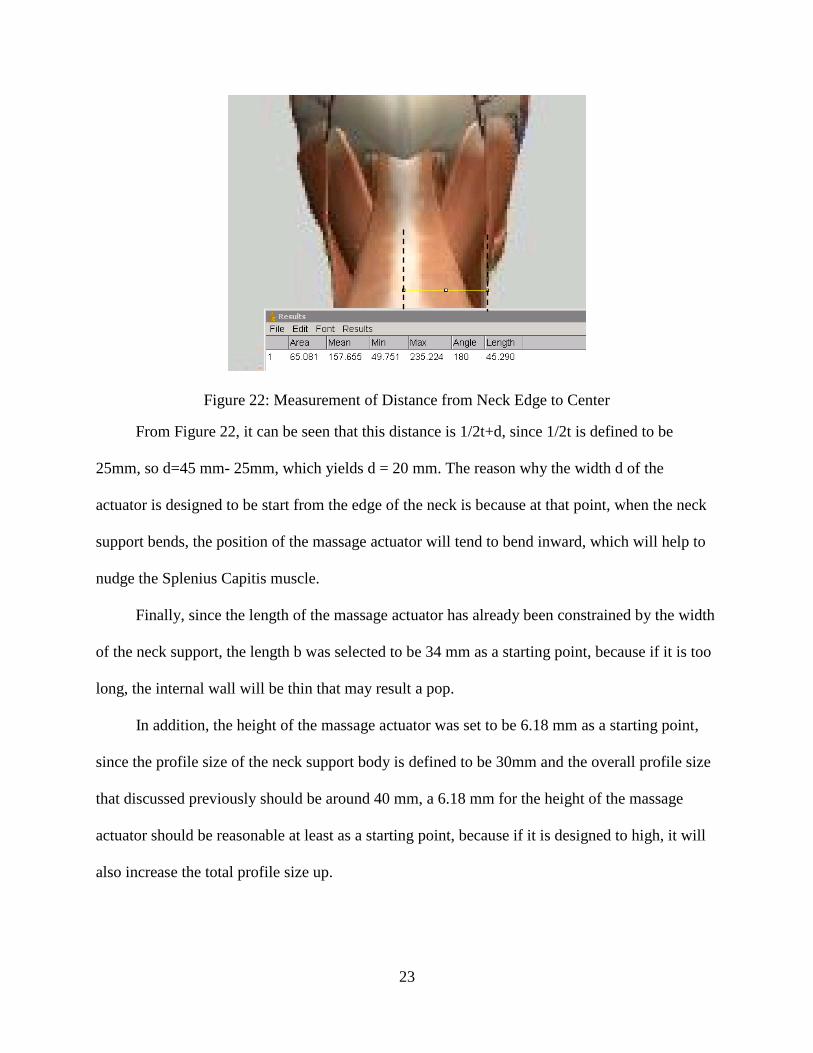
Figure 22: Measurement of Distance from Neck Edge to Center ................................................. 23
Figure 24: Solidworks Design for Neck Massager ....................................................................... 24
Figure 25: Massage Actuator Embedded in Neck Massager ........................................................ 25
Figure 26: Assembly view of neck massager and neck support ................................................... 26
Figure 27: ASTM D412 Standard Tensile Test Specimen ........................................................... 27
Figure 28: Ecoflex-30 Specimen in Wax Mold ............................................................................ 28
Figure 29: Stress-Strain Curve for Ecoflex-30 ............................................................................. 29
Figure 30: Yeoh Model Fitting for the Tensile Test Data ............................................................ 30
Figure 31: Abaqus FEM model for down-scale prototype ........................................................... 31
Figure 32: Abaqus FEM result ...................................................................................................... 32
Figure 33: Down Scale Pressure vs. Curvature ............................................................................ 33
Figure 34: Abaqus FEM model for down-scale prototype ........................................................... 34
Figure 35: Abaqus FEM result ...................................................................................................... 35
Figure 36: Pressure versus Curvature ........................................................................................... 36
Figure 37: 3D Printed Mold for Neck Support, Strain Limiting Layer and Massager ................. 38
Figure 38: Ecoflex-30 A and B mixing ......................................................................................... 39
Figure 39: Degassing for Ecoflex-30 material .............................................................................. 40
Figure 40: Material Poured into the Neck Support Mold ............................................................. 40
Figure 41: Material Poured into the Massager Mold .................................................................... 41
Figure 42: PDMS A and B Mixing ............................................................................................... 42
Figure 43: PDMS Material in Base Mold ..................................................................................... 43
Figure 44: De-molded Neck Support ............................................................................................ 43
viii
Figure 45: The Demolded Neck Massager ................................................................................... 44
Figure 46: Demolded Strain Limiting Layer ................................................................................ 44
Figure 47: Final Assembled Neck Support ................................................................................... 45
Figure 48: Final Assembled Prototype with Neck Massager........................................................ 45
Figure 49: Flows seen on Assembled Prototype ........................................................................... 46
Figure 50: Prototype Testing Setting ............................................................................................ 47
Figure 51: Prototype Testing Sample picture ............................................................................... 48
Figure 52: Prototype Testing Sample picture ............................................................................... 49

ix
LIST OF TABLES
Table 1: Horizontal Distance Measurement Results ..................................................................... 13
Table 2: Vertical Distance Measurement Results ......................................................................... 15
Table 3: Measurement Results of Splenius Capitis Distance ....................................................... 22

1
CHAPTER 1: INTRODUCTION
1.1 Background
The neck support plays an important role in alleviating the fatigue of people, especially
for those who are traveling a long distance. So in the current market, a kind of foam cushion
made U-shape pillow has been used as a neck support, as shown in Figure 1. However, it has
some disadvantages that cannot be easily overcome. For example, it uses big storage space when
unused. In addition, it cannot adjust its curvature and size to fit to different users. As a result, it
may aggravate the fatigue with the time. Furthermore, the traditional neck support made of foam
only provides single support for neck and does not provide more relaxing such as massage
function.
Figure 1: Foam cushion neck support
Source: http://www.google.com/patents?hl=en&lr=&vid=USPAT4345347&id=u1wyAAAAEBAJ&oi=fnd&dq=neck+support&printsec=abstract#v=onepage&q&f=false

2
Based on the constrains above and the high demands of the market, this research is
attempting to design a new neck support with features such as massage function and ability of
adjustment by using the soft robot mechanism and air actuation. Thanks to the development
of soft robot, the objective of the design can be achieved. The soft robot mechanism is
fabricated by using soft—often elastomeric—materials [1], such as silicone elastomer integrated
with pneumatic networks [2] inside, which are series inside cavities, to achieve a certain shape
change by actuation without any links and joints as in a traditional mechanism.
The soft robot mechanism has many advantages including its light weight and its ability
of large shape change. Prior to actuation, it will remain in a flat shape, while when actuating, the
shape will change according to the intensity of the air pressure pumped in. In addition, the
property of soft robot mechanism is ideal for massage because of its softness. With a well-
controlled actuation, it will act similar to action of muscle [3]. This research project will apply
such advantage features of soft robot to design and fabricate a massage neck support to increase
comfort and alleviate fatigue of the users.
1.2 Soft Robot
A soft robot is defined as: machines made of soft-often elastomeric-materials by the
robotics community [4]. The soft robot that this research involved is particular referred to an air
actuated and polymer fabricated with pneumatic networks embedded in side soft robots. For
example, Figure 2(a) illustrates a soft robot of this type and Figure 2(b) shows its actuation state.

3
Figure 2: (a) Soft robot gripper with no actuation (b) Soft robot gripper under air actuation
From Figure 2, it can be seen that the pneumatic networks are repeating in parallel. In the
middle of the wall of each chamber, a small air channel connects them together. A Solidworks
generated model is shown in Figure 3 for illustrating the inside structure.
Figure 3: Top Part of a Soft Robot Gripper with Pneumatic Net and Air Channel
The channel functions by allowing air to flow into each chamber during actuation. The
air actuation has several advantages such as it is easy to acquire, lightweight and low viscosity,
etc.
(a) (b)

4
In addition with the top part shown in Figure 3, the soft robot also consists of a bottom
part to seal pneumatic networks. Figure 4 shows the overall structure of a soft robot gripper.
Figure 4: Overall Structure of a Soft Robot Gripper
The bottom part that shown in pink in Figure 4, which is also called the strain limiting
layer, is made by a harder material than that used to fabricate the top part. In this way, upon air
actuation, the top of each chamber will tend to expand more than the bottom because of the
hardness difference. As a result, the overall shape change will tend to bend toward bottom.
Generally, for better actuation result, the material for fabricating the strain limiting layer is
ideally selected as inextensible of stretching but flexible of bending [5]. For example, in this
research, Ecoflex-30 (product of Smooth-on) with a shore hardness of 30 (ASTM D-2240
standard) [6] was selected as main body and polydimethylsioxane (PDMS, Dow Corning Sylgard
184) with a shore A hardness of 43 [7] was selected as the strain limiting layer. According to the
manufacturing datasheet [6][7], the Ecoflex-30 has very low hardness and very large strain range

5
that fracture above a maximum strain of 900%; while PDMS is more rigid that breaks at a
maximum strain of 150% so it will bend but cannot stretch when combined with Ecoflex-30
material. In addition, the Ecoflex-30 and PDMS are inexpensive and easy to work with, which
makes this material combination ideal for this research.
In fact, besides Ecoflex-30 and PDMS, the material can be chosen from a very wide
variety based on the actual needs. For example, for higher working pressure actuation, Elastosil
M4601 has been selected as extensible layer and a paper embedded in Elastosil M4601 has been
chosen as the strain limiting layer [8].
1.3 Soft Robot Manufacturing
Prior the fabrication of the soft robot, a mold needs to be made first as shown in Figure 5.
The mold can be fabricated by CNC machining, shape deposition manufacturing (SDM),
lithography and three-dimensional printing, etc.
Figure 5: Mold for Soft Robot Gripper
A brief fabrication process is illustrated by Figure 6. As in this case, the Ecoflex material
is prepared by mixing two components A and B in a 1:1 ratio together as shown in Figure 6a.
After mixing well, the Ecoflex material can be poured into the mold made previously as in figure

6
6b. In Figure 6c, a PDMS material that prepared same way as Ecoflex material except its 10:1
mixing ratio poured into the bottom part mold. Finally as shown in Figure 6d, after both Ecoflex
and PDMS material become solidified, they will be glued together by applying a thin layer of
PDMS material.
Figure 6: Mold for Soft Robot Gripper
1.4 Overview of Thesis
This thesis involves six chapters. Chapter 1 presents the introduction of soft robot, its
material, components and a brief description of its fabrication process. Chapter 2 discusses the
design for the neck support, including a brief description of a down scale prototype design,
discussion of full scale neck support design and neck massager design. Chapter 3 presents finite
a b
a
c
a
d
a

7
element analysis (FEA) process, including studying of material property, FEA model and FEA
validation results for both down scale and full scale prototype. Chapter 4 describes the
fabrication process and final assembly of the prototype. Chapter 5 discusses the prototype testing
process and its results. Finally, chapter 6 concludes the thesis and introduces future works.

8
CHAPTER 2: DESIGN OF MASSAGE NECK SUPPORT
2.1 Small Scale Prototype Design
A scaled down model for neck support was designed and fabricated before the fabrication
of the full scale model. The reason of making scaled down model is because they are easy and
fast to make and use relative a small amount of material. In addition, the experience gained by
fabricating down scaled prototype will aid of fabricating of the full scale prototype later
Figure 7 shows the CAD design of the mold for the prototype. In this fabrication the
mold was made by 3D printing.
Figure 7: CAD Design of Mold
Figure 8 (a) shows the dimension of the prototype and Figure 8 (b) represents the actual
prototype. Figure 9 shows the actuation state of this prototype.

9
(a)
(b)
Figure 8: Down Scale Prototype
Figure 9: Solidworks Design of Mold

10
2.2 Design Constraint for Full Scale Prototype
Based on the previous down-scale prototyping, a full scale prototype can be designed.
Several design constraints needed to be defined and analyzed well to provide guidance for the
final design.
The size of the neck support needs to be considered first. Because the design objective is
demanding a relative small device that still needs to be big enough to support the neck well.
Specifically, the main scenario for the usage of this design will be in the carbine environment
such as inside the car, so the size of the car chair will be the dominant limiting factor for the
maximum size of the design. Figure 10 shows the general dimension of a car seat with English
units.
Figure 10: Car Seat with Dimensions in Inches
Source: http://www.motorsportseats.com/corbeau/images/GTS%20II/GTSII-L.gif

11
As seen from Figure 10, the length of the seat head is about 240 mm and the shoulder
length is about 390mm. So this dimension range provides us a basic idea that the length of the
prototype should be bigger than 240 mm but smaller than 390mm. Although this dimension is
only for one specific car seat, but dimensions of other seats do not vary much.
Another limiting factor considered is the neck perimeter of human. According to the
statistical study from NCBI (national center for biotechnology information) that the threshold
value of human neck circumference for un-obesities is about 35.7 cm [9]. So 36 cm length
should be a good fit for most of people, since the scope of the research doesn’t include the
obesities. However, since the soft material itself has some ability of shape morphing, it will help
to compensate for the obesities case. In addition, since the neck support doesn’t need to cover
of the neck, generally a coverage of should be reasonable.
The profile size of the neck support also needs to be constrained. In order to understand
the necessary profile size of the neck support, a graphical measurement approach has been
adapted for this task. Figure 11 shows the human body figure that generated by Google
Zygotebody used for this analysis.

12
Figure 11: Human Body for Measurement
Source: http://www.zygotebody.com/#nav=6.35,81.5,231.25
An image analysis software called ImageJ, developed by National Institutes of Health,
was used for measurement [10]. The distance that constrains the neck support profile size was
measured from the edge of the back to the edge of the neck as shown in Figure 12. This distance
should hold a proportional relationship with the height of the human body. The height of human
body follows normal distribution [11] and the range of – to is considered to be the
normal range. In addition, the height considered here is the result of the average height for male
and female, since the difference height between male and female are not in the scope of this
research. According to the statistics data [12], the average height can be found as 1698 mm and
standard deviation is 0.64. So the range of height with in will be 1685.2 mm to 1710.8 mm.

13
Figure 12: ImageJ measurement
The scale of ImageJ of the overall height of Figure 11was set to be 1685.2 mm and
1710.8mm respectively to measure the distance. The measurement results of this horizontal
distance are summarized in table1.
Table 1: Horizontal Distance Measurement Results
Scale (mm) Measured distance (mm)
1685.2 55.95
1710.8 58.95
By taking the average of 55.95 mm and 58.95 mm, the average horizontal distance from
edge of back to the edge of neck is then calculated to be 57.45 mm. This number can be used to
constrain the profile height of the neck support. Since during the actuation, the profile size will

14
extend, so it should be smaller than 57.45 mm. In addition, based on previous experience,
approximately a 150% to 200% stretch in profile size is considered to be reasonable, because if
the stretch is very large, it may cause a fatigue failure and even a pop. Therefore, the profile size
can be approximate as 28.72 to 38.3 mm. 30 mm was picked up for the profile size of the body
part of the neck support, because it should leave room for other parts such as base part and the
neck massager.
Similar method was adapted to constrain the width of the neck support, which is the
distance from the bottom end of the neck to the top end of the neck as shown in Figure 13.
Specifically, the scale was set to be 1685.2 mm and 1710.8 mm. The measurement results of the
vertical distance are summarized in table 2.
Figure 13: ImageJ Measurement
15
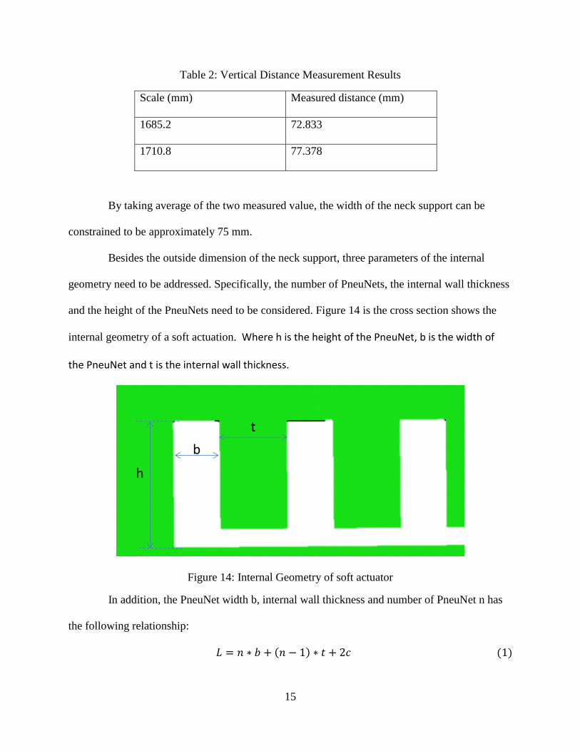
Table 2: Vertical Distance Measurement Results
Scale (mm) Measured distance (mm)
1685.2 72.833
1710.8 77.378
By taking average of the two measured value, the width of the neck support can be
constrained to be approximately 75 mm.
Besides the outside dimension of the neck support, three parameters of the internal
geometry need to be addressed. Specifically, the number of PneuNets, the internal wall thickness
and the height of the PneuNets need to be considered. Figure 14 is the cross section shows the
internal geometry of a soft actuation. Where h is the height of the PneuNet, b is the width of
the PneuNet and t is the internal wall thickness.
Figure 14: Internal Geometry of soft actuator
In addition, the PneuNet width b, internal wall thickness and number of PneuNet n has
the following relationship:
( ) ( )
h
b
t
16
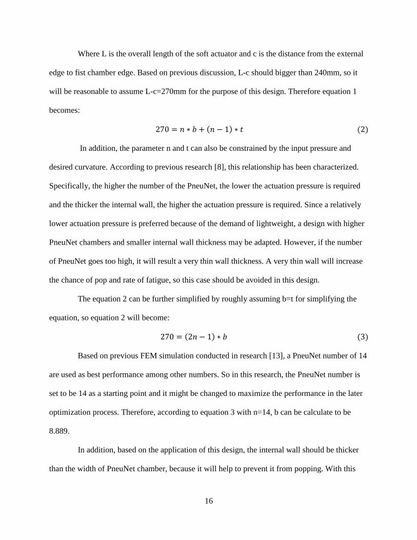
Where L is the overall length of the soft actuator and c is the distance from the external
edge to fist chamber edge. Based on previous discussion, L-c should bigger than 240mm, so it
will be reasonable to assume L-c=270mm for the purpose of this design. Therefore equation 1
becomes:
( ) ( )
In addition, the parameter n and t can also be constrained by the input pressure and
desired curvature. According to previous research [8], this relationship has been characterized.
Specifically, the higher the number of the PneuNet, the lower the actuation pressure is required
and the thicker the internal wall, the higher the actuation pressure is required. Since a relatively
lower actuation pressure is preferred because of the demand of lightweight, a design with higher
PneuNet chambers and smaller internal wall thickness may be adapted. However, if the number
of PneuNet goes too high, it will result a very thin wall thickness. A very thin wall will increase
the chance of pop and rate of fatigue, so this case should be avoided in this design.
The equation 2 can be further simplified by roughly assuming b=t for simplifying the
equation, so equation 2 will become:
( ) ( )
Based on previous FEM simulation conducted in research [13], a PneuNet number of 14
are used as best performance among other numbers. So in this research, the PneuNet number is
set to be 14 as a starting point and it might be changed to maximize the performance in the later
optimization process. Therefore, according to equation 3 with n=14, b can be calculate to be
8.889.
In addition, based on the application of this design, the internal wall should be thicker
than the width of PneuNet chamber, because it will help to prevent it from popping. With this

17
idea in mind, parameter b may be rounded down to 8 mm and then the corresponding parameter t
can then be calculated to be about 12 mm.
With the same consideration, the parameter h can also not be so high, because it will
result a thin top layer that will increase the chance of pop. So here, h may be reasonably set to be
23mm based on the overall profile size discussed above as a starting point, which can also be
optimized in optimization process.
2.4 CAD Design for Neck Support
Based on the parameters defined above, the neck support was designed in Solidworks
(Dassault Systèmes). In addition, the neck support consists of two components, the body and the
base part. Figure 15 shows the design with dimension.
Figure 15: Solidworks Design of Neck Support Body with Dimension in mm
As can be seen in Figure 15, the shape of the neck support is not rectangular with straight
edges. It is because the design needs to fit the contour of human neck that higher in center and
lower in edge. Figure 16 shows the strain limiting layer part of the neck support and Figure 17
represents the assemble view of the neck support.

18
Figure 16: Strain Limiting Layer Part of Neck Support
Figure 17: Neck Support Assembly View
2.5 Design of Neck Massager
Another objective of this research is to try to design a massager to further help to
alleviate the neck fatigue. The massager is also a soft actuator and it will be integrated into the
neck support discussed above.
In addition, the concept of the massager is to be able to be actuated and unactuated
periodically. In order to achieve this, a pump needs to be programed that it can compress and
extract air periodically. Figure 18 illustrates this concept.
Neck Support Body
Strain Limiting Layer

19
Figure 18: concept configuration of neck massager
However, due to the time constrain and the scope of this research, it has not been
programmed yet. But the neck massager was designed and fabricated and the design of the neck
massager is discussed below.
The concept of massage is to provide pressure on certain human muscle to help to relax
and alleviate fatigue [14]. A soft robot actuator can be designed to achieve this task by exerting
pressure force on the muscle under actuation.
Since the objective of this massager is to alleviate neck pain, the neck muscles need to be
studied first. According to method of massage therapy [15], Splenius Capitis is the muscle that
needs to be compressed. Figure 19 shows the anatomic view of Splenius Capitis.
Neck massager
Programmed pump
Air
20
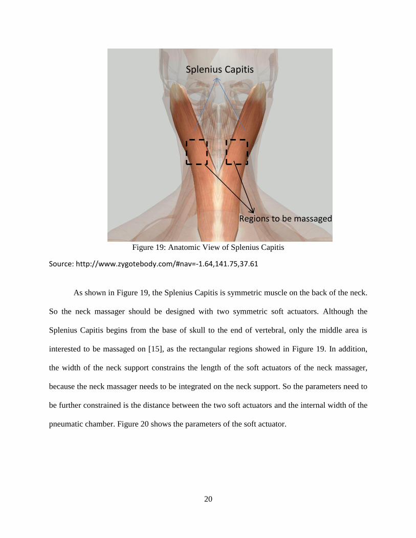
Figure 19: Anatomic View of Splenius Capitis
Source: http://www.zygotebody.com/#nav=-1.64,141.75,37.61
As shown in Figure 19, the Splenius Capitis is symmetric muscle on the back of the neck.
So the neck massager should be designed with two symmetric soft actuators. Although the
Splenius Capitis begins from the base of skull to the end of vertebral, only the middle area is
interested to be massaged on [15], as the rectangular regions showed in Figure 19. In addition,
the width of the neck support constrains the length of the soft actuators of the neck massager,
because the neck massager needs to be integrated on the neck support. So the parameters need to
be further constrained is the distance between the two soft actuators and the internal width of the
pneumatic chamber. Figure 20 shows the parameters of the soft actuator.
Splenius Capitis
Regions to be massaged

21
Figure 20: Parameters of Soft Actuators for Neck Massager
Where b is the length of the actuator, t is the distance between the two actuators and d is
the Pneumatic Network (PneuNet) chamber width.
In order to understand the actuator distance d, the distance between the two pairs of
Splenius Capitis needs to be measured. The graphical measurement method described previously
was adapted again in this measurement and in ImageJ the scale was set to be 1685.2 mm and
1710.8 mm as before. The measurement, which is shown in Figure 21, was taken the distance
from the center of the neck to the center of the Splenius Capitis muscle because of the symmetry.
In addition, the measurement results are summarized in table 3.
t
dSoft actuator
b

22
Figure 21: Measurement of Splenius Capitis Distance
Table 3: Measurement Results of Splenius Capitis Distance
Scale (mm) Measured distance (mm)
1685.2 24.829
1710.8 25.426
By taking the average of the two measurement result and round to nearest integer, the
distance is defined to be about 25 mm. Therefore the distance between the two actuators can be
selected to be 50 mm.
Furthermore, the distance from the edge of the neck (measured from the tangent line) to
the center of cervical vertebra was measured as about 45 mm, as shown in Figure 22.
23
Figure 22: Measurement of Distance from Neck Edge to Center
From Figure 22, it can be seen that this distance is 1/2t+d, since 1/2t is defined to be
25mm, so d=45 mm- 25mm, which yields d = 20 mm. The reason why the width d of the
actuator is designed to be start from the edge of the neck is because at that point, when the neck
support bends, the position of the massage actuator will tend to bend inward, which will help to
nudge the Splenius Capitis muscle.
Finally, since the length of the massage actuator has already been constrained by the width
of the neck support, the length b was selected to be 34 mm as a starting point, because if it is too
long, the internal wall will be thin that may result a pop.
In addition, the height of the massage actuator was set to be 6.18 mm as a starting point,
since the profile size of the neck support body is defined to be 30mm and the overall profile size
that discussed previously should be around 40 mm, a 6.18 mm for the height of the massage
actuator should be reasonable at least as a starting point, because if it is designed to high, it will
also increase the total profile size up.

24
3.3 CAD Design for the Neck Massager
Since the neck massager needs to be able to integrate on the neck support, the contour of
the neck massager should be identical to that of the neck support.
In addition, since the neck massager will directly contact with human neck, ergonomics
needs to be considered for comfort. In order to achieve ergonomic design, straight edges need to
be avoided. Figure 23 (a) shows isometric view of the Solidworks design for the neck massager
and Figure 23 (b) and (c) shows the side views of the neck massager.
(a)
(b)
(c)
Figure 23: Solidworks Design for Neck Massager
It can be seen from Figure 23 (c) that the contour is designed to feature with curved
surface, it will help to increase the comfort because it will has a better fit for human neck than
flat surface. In addition, the total profile size of the neck massager is designed to be 10 mm.
From Figure 23 (b), it can be seen that it also featured with a curved surface, because
there should be some clearance between the neck and neck support in order to allow head

25
movement and reduce heat accumulation around the neck, which will also help to increase the
comfort. In addition, in the middle of the neck massage, it can be seen that it featured with a
curved sunken surface. The reason for design this sunken surface is because it will help the neck
massager fit closer to the neck, which will allow the massage actuator has a better contact to the
neck and by reducing the thickness of the middle part, it will also help the neck support for easier
bending.
In addition, the massage actuators are embedded inside the neck massager, as shown in
Figure 24.
Figure 24: Massage Actuator Embedded in Neck Massager
The massage actuator is designed with higher height on side edge and lower height on the
outside edge as can be seen in Figure 24. The inside surface of the massage actuator that is
designed to have thicker outward wall and thinner inside wall is because during the actuation, the
thinner inside wall will easier to deform than the thicker outside wall, so the pneumatic actuators
will tend to balloon up toward inside, which will help to nudge Splenius Capitis muscle.
Massage actuator

26
Figure 25 represents the assembly view of the neck massager that shown in green
integrated on the neck support.
Figure 25: Assembly view of neck massager and neck support

27
CHAPTER 3: FINITE ELEMENT ANALYSIS FOR DESIGN VALIDATION
3.1 Study of Material Properties
One of the challenges of design soft robot is to understand the material property, because
the property of the material will affect the final shape change. For instance, the stiffer the
material, the less the shape can deform and vice versa. In addition, since the material to be used
for making soft robot is hyper-elastic and shows a non-linear behavior [16], understanding the
Stress-Strain curve is necessary to perform finite element analysis by applying an appropriate
strain energy model [16].
A uniaxial tensile test was performed to understand the material property followed by
ASTM D412 standard [17]. According to the tensile test standard, a tensile test specimen was
fabricated first as shown in Figure 26 with dimension.
Figure 26: ASTM D412 Standard Tensile Test Specimen
115 mm
33 mm
25
mm

28
In addition, a wax mold was made by CNC machining in order to make the specimen.
Figure 27 shows the mold and the Ecoflex-30 specimen inside the mold.
Figure 27: Ecoflex-30 Specimen in Wax Mold
The tensile test was performed at room temperature with a uniform grip separating rate
of 500mm/min. A 50 KN load was also used for this tensile test as the tensile testing machine’s
general set up. Figure 28 represents the uniaxial tensile test result.

29
Figure 28: Stress-Strain Curve for Ecoflex-30
Figure 28 illustrates a highly non-linear stress-strain behavior for the exoflex-30 material.
Based on this graph, a strain energy model can be curve fitted to describe this stress-strain curve.
Based on observation of the trend of the curve, it seems a Yoeh model can be a proper fit. The
strain energy equation of the Yeoh model [18] is described as follows in equation 4:
∑ ( )
( )
Where
and λ is the principal stretch that follows with the relationship of
λ=ϵ+1. The experimental stress-strain curve is fitted by Eq. (4) in Mathematica 9 (Wolframe

30
Inc.) as shown in Figure 29, where the solid line represents the Yeoh model curve and the dots
represent the tensile testing raw data.
Figure 29: Yeoh Model Fitting for the Tensile Test Data
It can be seen that the testing data follows very close to the Yeoh model curve, so the
Yeoh model can be used to describe the behavior of the Ecoflec-30 material. The Yeoh model
coefficients were also determined as
.
3.2 Finite Element Analysis Model
A FEM approach was used to validate the geometric design of the neck support and to
predict the curvature under certain pressure. Through the FEM, it is investigated to see if it will

31
be actuated as expected and the relationship between the curvature and pressure is also interested
to help for pump section.
In addition, the FEM model for the down-scale prototype was created before the full
scale prototype model. Because the feature of the down-scale prototype is simpler, it is easier for
simulation.
Abaqus 6.13, Computer Aided Engineering (CAE) software (Simulia, Dassault Systems)
was used to perform the FEM analysis. The Solidwoks parts that developed previously were
saved as STEP file and import into Abaqus as solid elements. In addition, the gravity was
ignored in this case and the air pressure is applied to the entire internal cavity surface. The
boundary condition was set as symmetry with (U1-U2=U3=U4+UR1=UR2=UR3=0) at the edge.
Figure 30 shows the FEM model created in Abaqus for the down-scale prototype with pressure
and boundary condition labeled.
Figure 30: Abaqus FEM model for down-scale prototype
The material property was set to be hyperelastic for both Ecoflex-30 and PDMS material.
Both materials are assumed to be incompressible so that the Ecoflex-30 was modeled by Yeoh
Pressure applied to all internal surfaces
Boundary condition set to be fixed and symmetric

32
Model and PDMS was modeled by Neo-Hookean. In addition, the Ecoflex-30 tensile testing data
was imported into Abaqus for Yeoh model and the coefficient of the Neo-Hookean for PDMS
was set to be C10=0.92, which is one half of the shear modulus that presented in [16].
Figure 31(a) shows the Abaqus FEM result with air pressure of 0.2 MPa and Figure 32(b)
shows the section view.
(a)
(b)
Figure 31: Abaqus FEM result

33
In addition, the relationship between the pressure and the curvature is also interested and
in order to understand this relationship, several FEM analyses are needed to be run. Then the XY
coordinates of the deformed points on the body were picked and imported into Matlab
(MathWorks) for circle fit in order to find the radius of the curve. Since the curvature is the
inverse of the radius, the relationship between curvature and pressure can be found. Figure 32
shows the plot of pressure versus curvature with the pressure ranges from 0 to 0.25 Mpa. The
plot makes physical sense that the curvature increases with increase of pressure.
Figure 32: Down Scale Pressure vs. Curvature
As can be seen from Figure 31 and Figure 32, the simulation job succeeds to predicting the
shape deformation. So a similar simulation method can be used for simulating the more
complicated full scale model. Figure 33 shows the FEM model for the full scale prototype. The
0 0.05 0.1 0.15 0.2 0.250
0.005
0.01
0.015
0.02
0.025
0.03
0.035
0.04
0.045
0.05
Pressure Mpa
Curv
atu
re m
m- 1
Down scale simulation pressure Vs curvature

34
pressure applied both in the pneumatic networks in the neck support body and the internal
surfaces of the massage actuators.
Figure 33: Abaqus FEM model for down-scale prototype
In addition, the material properties for the neck support body and massager was defined as
Ecoflex-30 while the material property for the strain limiting layer was set to be PDMS. Figure
34 (a) shows the Abaqus FEM result with air pressure of 0.2 MPa and Figure 34(b) shows the
section view.
Pressure applied to neck
support body internal surfaces
Boundary condition set to be fixed and symmetric
Pressure applied to massage
actuator internal surfaces

35
(a)
(b)
Figure 34: Abaqus FEM result
The FEM result as shown in Figure 34 is within the design expectation, which implies the
parameters selected above are feasible. A pressure versus curvature curve was also created for
the full scale prototype model as shown in Figure 35.

36
Figure 35: Pressure versus Curvature
From Figure 35, it can be seen that curvature increases as the pressure increase but slope
deceases after 0.05Mpa and the curvature doesn’t change much after pressure reaches 0.1 Mpa.
So based on this information, the pressure regulator can be selected as within the range of 0 to
0.2Mpa for this prototype. In addition, this plot will be used to compare with the testing results to
see how well the FEM results can simulate the real testing results.
0 0.02 0.04 0.06 0.08 0.1 0.12 0.14 0.16 0.18 0.20
0.002
0.004
0.006
0.008
0.01
0.012
0.014
0.016
0.018
pressure Mpa
Curv
atu
re m
- 1
Pressure VS Curvature

37
CHAPTER 4: MANUFACTURING PROCESS
4.1 Overview
The general soft robot manufacturing process takes four steps. The first step is to create
the mold for the soft robot. This is followed by mixing and pouring Ecoflex material into the
mold. Then the part is de-molded from the mold. The last step is to assemble the two by sealing
the pneumatic networks by applying a thin layer of PDMS material to seal the top and bottom
part together. The manufacturing involved in this research follows this process.
4.2 Fabricate the Mold
In this research, the mold was fabricated by 3D printing by using Makerbot Replicator
2X (MakerBot Industries, LLC) and the mold material is Acrylonitrile butadiene styrene (ABS).
The Solidworks model of the mold to be printed was saved to STL file and imported into
Makerware 2.4.1 software (MakerBot Industries, LLC). The Makerware software was used to
slice the part in order to generate the G code and several settings, such as the extruding
temperature, extruding speed and plate temperature, ect., for printing the part can also be
adjusted in the software.
In addition, since the printing volume for the Makerbot Replicator 2X is only 24.6 x 15.2x
15.5 cm [19], the building plate cannot fit the designed mold. So the mold was cut half by half in
Solidworks before save as STL file and after printing, the two half parts can be glued together.
In Makerware, the extruder temperature was set to be 230 Celsius degree and the build
plate temperature was set to be 110 Celsius degree. The extruding speed was setup to be 90 mm/s
and 150 mm/s while traveling. In order to reduce the building time, the layer height was set to be

38
0.27mm and infill was set to be 10% with 2 shells, because the mold does not need very detail
resolution. This setting was held same for all the mold printings in this research.
Three molds need to be printed that for the neck support body, base and massager. Since
all of the molds need to be printed half by half, six printing jobs needed to be conducted. Figure
36 (a) shows the mold printed for neck support body, (b) shows the mold for base and (c) shows
the mold for massager.
(a)
(b)
(c)
Figure 36: 3D Printed Mold for Neck Support, Strain Limiting Layer and Massager

39
4.3 Soft Material Pouring
Two materials are involved in this research that is Ecoflex-30 and PDMS material
respectively. Both of the material are consists with liquid A and B part and they needs to be
premixed before pouring. The mixing ratio for Ecoflex-30 material is 1:1 while the mixing ratio
for the PDMS material is 10:1.
Ecoflex-30 was the first material prepared and to be poured. The A and B part of the
material were mixed together by 1:1 weight ratio in a cup, as shown in Figure 37.
Figure 37: Ecoflex-30 A and B mixing
The mixed material was stirred well and then put in a degassing chamber to remove the
air bubbles inside the material. Because if the air bubbles remain inside the material, when it
solidifies, it will become porous that will reduce mechanical strength. Figure 38 shows the
degassing process.

40
Figure 38: Degassing for Ecoflex-30 material
After the material has been degassed, it will be ready for pouring into the mold. The
pouring flow rate should be kept slow and constant to avoid embedding air bubbles inside.
Figure 39 represents the poured material in the mold. If any air bubble was appear in the
material, a hypodermic needle will be used to remove the bubbles. In fact, the Ecoflex-30
material is found as not likely to contain air bubbles.
Figure 39: Material Poured into the Neck Support Mold
After pouring the material into the mold, it is ready to cure. Due to the limitation of the
lab equipment of unavailable of a lab oven, the material was cured at room temperature, which
was about four hours for the Ecoflex-30 material. But if equipped with a lab oven, it can be cured
41
faster at higher temperature, because higher temperature will accelerate the reaction speed
between the A and B part of the material.
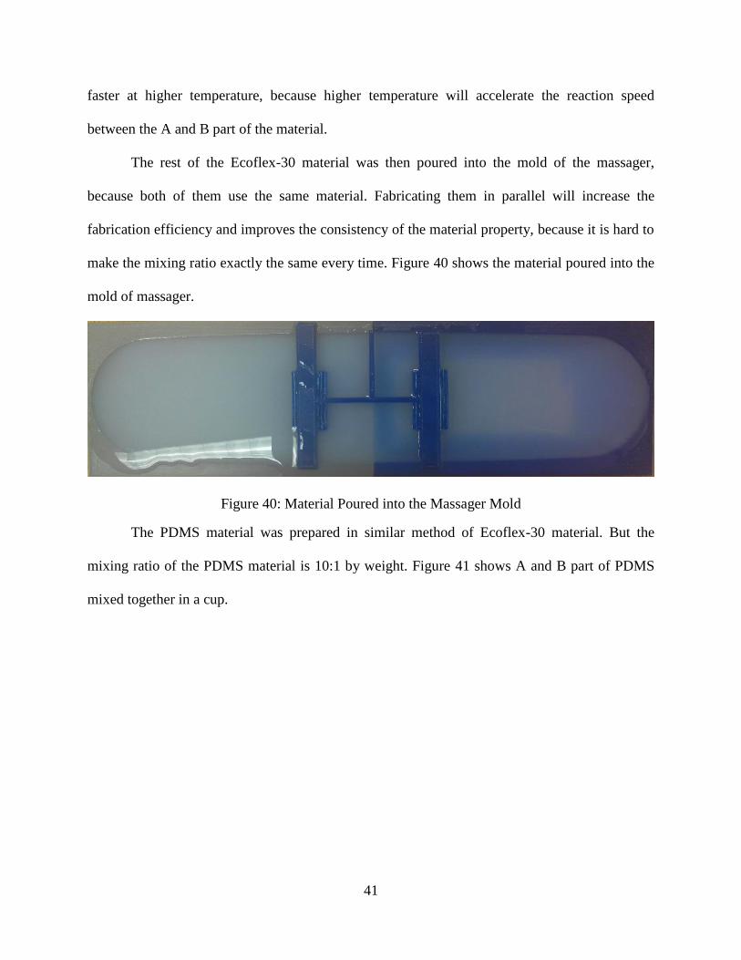
The rest of the Ecoflex-30 material was then poured into the mold of the massager,
because both of them use the same material. Fabricating them in parallel will increase the
fabrication efficiency and improves the consistency of the material property, because it is hard to
make the mixing ratio exactly the same every time. Figure 40 shows the material poured into the
mold of massager.
Figure 40: Material Poured into the Massager Mold
The PDMS material was prepared in similar method of Ecoflex-30 material. But the
mixing ratio of the PDMS material is 10:1 by weight. Figure 41 shows A and B part of PDMS
mixed together in a cup.

42
Figure 41: PDMS A and B Mixing
After the mixing of the PDMS material, a well stir was performed to make sure they
mixed with each other well and then the mixed material was degassed in the degassing chamber.
It needs several runs for the degassing process in order to fully remove the air bubbles inside,
because the air is harder to come out from PDMS material than Ecoflex-30 material. After the
mixed material has been degassed, it was ready for pouring. Pouring for the PDMS material need
to be slower and need to pour evenly than for Ecoflex-30 material, because it is more viscous
than the Ecoflex-30 material. Again, a hypodermic needle was used to remove the observed air
bubbles. Figure 42 shows the PDMS poured into the base mold.

43
Figure 42: PDMS Material in Base Mold
In addition, the curing time for the PDMS material is measured to be about 48 hours at
room temperature in the lab, which is much slower than the curing time of Ecoflex-30 material.
Increasing the temperature will significantly reduce the curing time, for instance, the material
can cured within 10 minutes at 150 Celsius Degree [20].
4.4 De-mold the Part
After the material cured, it can be removed from the mold. The material was peeled-off
very carefully with a gentle force. Figure 43-45 show the cured neck support, massager and base
after de-molding.
Figure 43: De-molded Neck Support

44
Figure 44: The Demolded Neck Massager
Figure 45: Demolded Strain Limiting Layer
4.5 Final Assembly
The parts that were demolded from the mold were ready for assembly. The neck support
and base were assembled together first and then the massager was assembled.
PDMS material was used as the glue to assemble the neck support body and strain
limiting layer together. Same procedure was performed to prepare for the PDMS material. After
prepared the material, it was poured on the top of the base as a thin layer and then the neck
support body was placed on top of that. Another 48 hours was waited for completely cure. Figure
46 shows the assembled neck support body and its strain limiting layer.

45
Figure 46: Final Assembled Neck Support
Then the neck massager was assembled on the back of the strain limiting layer, which is
the opposite side of the neck support body. PDMS material was used again for assembly the
massager. The prepared PDMS material was poured on the surface of the strain limiting layer to
form a thin layer and then the massager was placed on the top and cured for another 48 hours.
Figure 47 shows the assembled neck support with its massager.
Figure 47: Final Assembled Prototype with Neck Massager
4.6 Observations of Prototype
Before real testing for the prototype, it was examined by observation to see if there is any
flaw on the prototype due to manufacturing mistake. There was no bubbles observed on any part
Neck support body
Strain limiting layer
Neck Massager Neck Support Body Strain limiting layer

46
of the body and also no crack or break parts be observed and the components were assembled
firmly without unsealed part that make cause an air leakage.
However, some flaws have been found. The major one is the internal air channel has been
sealed by the gluing layer, which causes the air cannot flow to all the pneumatic networks. This
is due to manufacturing mistake. Specifically, the position during assembly is the neck support
body was on top of the strain limiting layer and because of the material is very soft that the
weight compressed the air channel to touching the gluing layer, which causes the air channel
being sealed. It is very easy to resolve simply by putting the strain limiting layer on top of the
neck support body during assembly.
In addition, some other minor flaw has also been observed that the length of the base was
a little bit shorter than the length of the neck support body while the length of the massager was
slightly longer as shown in Figure 48. It is because the mold is fabricated half by half and then
glued together, which reduced the precision. Specifically, the 3D printed part may not have a
straight vertical wall, so it needs to be flattened before glued the two parts together, otherwise it
will leave cracks on the glued surface, which will cause a leakage when pouring the material. But
flatten the surface needs to remove some material, which causes shorten in length. Several
strategies can avoid this issue, such as adapting a 3D printer that has bigger build volume.
However, it is not a big issue to affect the result and it can be improved in future manufacturing.
Figure 48: Flows seen on Assembled Prototype

47
CHAPTER 5: PROTOTYPE TESTING
5.1 Prototype Testing Setting
Since the full scale prototype is not functional due to manufacturing errors and a new
prototype hasn’t been made yet, the full scale prototype cannot be tested at this point. Instead,
the down scale prototype was tested first.
The air provided in the lab has been used for actuating the prototype. A pressure regulator
was used to control the air at desired pressure and a pressure gauge was connected on the
regulator to display the controlled pressure. In addition, a camera was placed vertically above the
prototype and a grid paper was placed under the prototype. Figure 49 represents the testing setup.
Figure 49: Prototype Testing Setting
The pressure increase from low to high till fully actuate the prototype and then decrease
from high to low that back to original shape. In addition, the pressure was slowly increases and
Grid paper
Prototype
Pressure gaugePipe
Pressure
regulator
Camera
Shelf

48
decreases to make the prototype in a steady state. Several pictures were taken during this
process. Figure 50 shows a sample picture.
Figure 50: Prototype Testing Sample picture
5.2 Prototype Testing Results
A graphical method was used to analysis the pictures to find the relationship between the
curvature and the pressure. Specifically, ImageJ software was used to select several points along
the curved surface and then the x and y positions of these points were imported into Matlab for
circle fitting in order to find the radius of the circle, which is the inverse of the curvature. Figure
51 shows the plot of pressure versus curvature.

49
Figure 51: Prototype Testing Sample picture
From Figure 51, it has been observed that the curve from low to high and from high to
low do not repeat with each other. Specifically, it has been observed that at certain pressure, the
curvature of the prototype is larger from high to low than that from low to high. It is because
when the pressure is from high to low, the curvature is higher because of the ballooning effect;
when pressure goes from low to high, an extra pressure is required to stretch the internal wall and
in addition to bending the stiffer PDMS layer.
Furthermore, when compared with the simulation result in Figure 32, several deviations
has been found. The most obvious difference will be the shape of the curve. In Figure 32, it can
be seen that the curvature initially increases fast with the pressure and then slows down, while in
Figure 51, it shows the curvature doesn’t change much at beginning then it increase suddenly and
0.012 0.013 0.014 0.015 0.016 0.017 0.018 0.019 0.02 0.021 0.0220
0.005
0.01
0.015
0.02
0.025
0.03
0.035
0.04
0.045
pressure Mpa
curv
atu
re m
m- 1
Down scale prototype testing result
P from low to high
P from high to low

50
finally, the slope of the curve decreases approximately to zero with further increase of pressure.
The sudden increase of the curvature is called a snap through effect, which means a large
deformation with essentially no additional stress input [21]. However, this snap through effect
may not be captured by the simulation, because in the simulation, the pressure will be gradually
applied, which result a smooth curve. Another reason may from the testing part, because the
friction between the prototype and the ground may prevent the prototype from bending, which
may significant at lower pressure.
In addition, another major difference is that the scale of the pressure is different. The
pressure value in Figure 32 is nearly 10 times larger than that in Figure 51. This may mainly due
to the tensile testing results. Due to the limitation of the tensile testing machine, the testing
situation was not ideal. For instance, the only available load cell was 50 KN, which is very large
for this very soft material. So the testing was operated in the far end of the capacity of the load
cell, it will significantly affect the accuracy of the testing result. In addition, the tensile test
gripper was also not ideal for the soft material, which exerts very large force on the specimen
that result a break at tip of the gripper during tensile test rather than in the middle of the
specimen.
However, the final curvature agrees with each other in both simulation and testing results.
In both plots, the curvature approaches to 0.045 when fully actuated at 0.2 Mpa and 0.02
Mpa in simulation and testing results respectively. Since in this research, only the final curvature
is interested, so the simulation was be able to accurately predict the curvatures near full
actuation.

51
CHAPTER 6: CONCLUSIONS
The purpose of this research is to design and fabricate a neck support with massage
function by using soft robot mechanism to help to provide more comfort for the users. The
application of soft robot mechanism to the neck support and massager has not been explored
previously by other researches. So this research has attempted to validate the design concept and
feasibility.
6.1 Contributions
Recently, more and more attentions have been placed in the field of soft robot [5] [8] [22]
[23]. The soft robot mechanism has been applied to many filed of applications, such as multigait
soft robot [24], robotic tentacles [23] and soft robot gripper [5], etc. However, the application of
soft robot on neck support and massager has not been explored yet. This research explored the
possibility of applying soft robot mechanism in neck support and massager application.
Although at this point, the full scale neck support fabricated in this research hasn’t been
tested yet due to manufacturing error, a down scale prototype has been tested and validated that
it has the ability to bending to different curvatures based on the input pressure. In addition, FEA
simulation model of the full scale prototype has shown that it has the ability for individual
adjustment. Furthermore the soft massager significantly reduces the weight compared to
traditional motor driven hard massager [25].
This thesis has outlined the methods adapted in the design and prototype process. One
could get benefit from the approaches and results described to better optimize and others could
also learn from this research to redesign the neck support or other related applications.

52
6.2 Additional Applications
This paper has described the design approaches for a massage neck support. The design
approaches can also be used to design for other application besides neck support, such as for the
application of leg and hand rehabilitation.
6.3 Future Work
The full scale prototype will be refabricated based on the lessons learned from the current
prototype fabrication. A test will also be conducted for the full scale prototype. In addition, a
new tensile test with proper tensile testing devices will be conducted to get more accurate stress-
strain curve for the material so that the simulation will be improved to match the real testing
results. Furthermore, the neck support and its massager can be further improved and optimized.
Due to the time constrain of this research, some of the parameters were just selected as a
reasonable starting points without optimization, so optimization process can be performed to
optimize it for best performance in the future work, such as reducing the pressure, increase the
force produced by the massager and reduce the total weight.
6.4 Summary
A neck support with massage function was designed, fabricated and tested. This research
has applied the soft robot mechanism to a previously unexplored application. The final prototype
was fabricated but due to fabrication error, it is not functional. However a down-scale prototype
was also fabricated and successfully tested, which proves that the design is feasible and it is
beneficial to apply soft robot techniques in the neck support and massage application. This
research will be beneficial to those who interested in the related area of soft robot application and
it will further ignite the interests in exploring new applications of soft robot.

53
BIBLIOGRAPHY
[1] R. H. A. Quaid, "Proc. IEEE Int. Conf. Rob. Autom.," Minneapolis, 1996.
[2] A.Needleman, Int. J. Solids Structure, 1977, 13, 409-421.
[3] H. F. Schulte, "The Application Of External Power In Prosthetics And Orthotics,"
Washington, 1961.
[4] A. Crespi, A. Badertscher, A. Guignard, A. J. Ijspeert, Robot Auton. Syst, pp. 50,163-175,
2005.
[5] F. Ilievski, A. Mazzeo, R. Shepherd, X. Chen, G. Whitesides. Angew, Chem. Int. Ed., pp. 1890-
1895, 2011.
[6] "Smooth-on ecoflex-30 shore hardness," Smooth-on Inc., [Online]. Available:
www.smooth-on.com.
[7] "PDMS shore A hardness," Down Corning, [Online]. Available:
http://www.dowcorning.com/applications/search/products/Details.aspx?prod=01064291.
[8] B Mosadegh, P. Polygerinos, C. keplinger, S. Wennstedt, R.F. Shepherd, U.Gupta, J. Shim, K.
Bertoldi, C.J. Walsh, G.M. Whitesides, Adv. Funct. Mater., 2013, 1-8.
[9] Ben-Noun L, Sohar E, Laor A, "Neck circumference as a simple screening measure for
identifying overweight and obese patients," NCBI, Aug 2001 . [Online]. Available:
http://www.ncbi.nlm.nih.gov/pubmed/11500527.
[10] "Image J," National Institutes of Health, [Online]. Available: http://imagej.nih.gov/ij/.

54
[11] "The Z-score or standard deviation classification system," World Health Organization,
[Online]. Available: http://www.who.int/nutgrowthdb/about/introduction/en/index4.html.
[12] M.A. McDowell, M.P.H., C. D. Fryar, R. Hirsch, and C. L. Ogden, "Anthropometric Reference
Data for Children and Adults," Advance Data, p. 361, 2005.
[13] P. Polygerinos, S. Lyne, Z. Wang, L. F. Nicolini, B. Mosadegh, G. M. Whitesides, C. J. Walsh,
"Towards a Soft Pneumatic Glove for Hand Rehabilitation," in IEEE int. Conf. Intelligent
Robots and Systems, Tokyo, Japan, 2013.
[14] P. Weerapong, P. A. Hume, G.S. Kolt, "The Mechanisms of Massage and Effects on
Performance,Muscle Recovery and Injury Prevention," Sports Medicine , pp. 235-256.
[15] J. H. Clay, D. M. Pounds, Basic Clinical Massage Therapy, Lippincott Williams & Wikins,
2006.
[16] A.F.Bower, "Hyperelasticity time independent behavior of rubbers and foams subjected to
large strain," in Applied Mechanics of Solids, CRC Press, pp. 93-103.
[17] ASTM D412, "Standard Test Methods for Vulcanized Rubber and Thermoplastic
Elastomers," [Online]. Available:
https://law.resource.org/pub/us/cfr/ibr/003/astm.d412.1968.pdf.
[18] O. Yeoh, Rubb. Chem. Tech., vol. 66, p. 754, 1993.
[19] "Makerbot Replicator 2X Specification," Makerbot Inc., [Online]. Available:
http://store.makerbot.com/replicator2x.
[20] "PDMS datasheet," Dow Corning, [Online]. Available:
http://www.dowcorning.com/applications/search/products/Details.aspx?prod=01064291.

55
[21] R. Seydel, Practical Bifurcation and Stability Analysis, 3rd. ed., New York, USA:
Interdisciplinary Applied Mathematics Vol.5. Springer, 2010.
[22]
[23]
A.A. Strokes, R.F.Sherpherd, S.A.Morin, F.llievski, G. M. Whitesides, Soft Robotics, vol. 1, p.
70, 2013.
R.V. Martinez, J.L. Branch, C. R. Fish, L. Jin, R.F. Shepherd, R.M.D. Nunes, Z. Suo, G. M.
Whitesides,"Robotic Tentacles with Three-Dimensional Mobility Based on Flexible
Elastomers", Adv. Mater., Vols. 25, pp. 205-212, 2013.
[24] R.F. Shepherd, F.llievski, W. Choi, S.A. Morin, A.A. Strokes, A.D. Mazzeo, X. Chen, M. Wang,
G.M. Whitesides, "Multigait Soft Robot," PNAS, Vols. 108, No.51, Dec. 2011.
[25] K.C. Jones, W. Du, "Develoopment of a Massage Robot for Medical Therapy," IEEE/ASME
inter., conf., AIM, 2013.