Embed Size (px)
Citation preview

Design Methodology for High-Level Model Based on an Eight Bit Entertainment System
Alejandro Lizaola, Ricardo D. Castro, Gilberto Beltran. Manuel Salim and Alejandro Moreno
Department of Electronics, Systems and InformaticsInstituto Tecnológico y de Estudios Superiores de Occidente (ITESO)
Guadalajara, Mexico, 45090
Intel & Iberchip XVII, February 2011

Outline
Introduction
Theory
Main Block Description
Design Methodology
Verification Strategies
Results
Conclusions
Future Work

Introduction
This presentation is about a design methodology for a high-level model based on an 8 bit entertainment system.
Verification strategy proposed for this project is based on reverse engineering.
Design and architecture of the group of reference model models has been identified .
Coding and Verification development has been a challenge.
It’s been a merge between a Software and Hardware verification methodology.

Theory
Reverse Engineering:
It has the goal to obtain information from a product to determine its structure, function and operation.
Emulator:
It is a software that allows certain computer programs to run on a different platform than the one they were originally written for.

Reference Model:
It is a high level description of a system, chip, block, or component to obtain the expected values that will compare with the obtained values and declare a failed or passed test.
Verification:
It is the process to determine that an implementation behaves according to a given set of requirements for all possible scenarios.
…Theory

Main Block Description

Design
1. Comprehend and understand the functionality of the NES.
2. Comprehend and understand the operation of the NES.
3. Election of emulator.
4. Reference model design.
5. Implementation of reference model main blocks.
6. Verify the operation of each block of the reference model.
7. Integrate reference model modules.
8. Verify reference model integration.
Verification Strategies
Reference Model Verification:
Verification Plan:
The verification plan is defined in base of the NES console. Through the specification of the console, all functional areas as well as monitors and checkers were analyzed and the coverage was chosen. This document is useful for all those who are working in the planning and execution of the console verification.
…Verification Strategies

Results
Triangular channel outputs for crystali game

…Results
White noise channel outputs for crystali game

…Results
Audio buffer outputs for crystali game
…Results
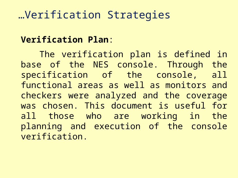
Scroll results for crystali game
Sprites results for crystali game

Conclusions
A Nintendo emulator for PC was selected. A reference model was implemented based on this emulator and implemented in SystemVerilog. The model was created in a modular way using reverse engineering and design tools for programming high-level languages. Model functionality was verified.
SystemVerilog makes easer the reference model implementation because it provides a high level modeling abstraction with a lot of capabilities to implement and verify a design developed in any hardware description language.

…Conclusions
The Methodology proposed was based in software debugging techniques, so this combines both mechanics by mapping the hardware validation to software validations process.
The performance of the model behaves as expected.

Future Work
• Mappers and more expansion chips can be implemented.
• An interface between CPU and controllers can be designed.
• The reference model can be done to be synthesized and to be downloaded into a FPGA. With this reference model a verification environment can be done to validate a RTL prototype .
• The system must further refine the PPU module, especially a variable called "display" to have the optimal functioning of the entire system.

Slides Background
Central Processing Unit:
The CPU emulated by the NES is an 8-bit microprocessor produced by Ricoh based on MOS Technology 6502 core. The NTSC version (North America and Japan) of the console use the Ricoh 2A03 (or RP2A03), which operates at 1.78MHz, PAL version (Europe and Australia) use the Ricoh 2A07 (or RP2A07), this is identical to version NTSC with the difference that it works on 1.66MHz.

Slides Background
Audio Processing Unit:
The APU is responsible for generating the game sound. It is implemented in two chips, RP2A03 for NTSC and RP2A07 for PAL. The APU has 5 channels:
1. Square channel, frequency ranges 54 Hz – 28 KHz.
2. Square channel, frequency ranges 54 Hz – 28 KHz.
3. Triangle channel, frequency ranges 27 Hz – 56 KHz.
4. Noise channel, LFSR, two modes and sixteen programmable frequencies.
5. DPCM channel.

Slides Background
MAPPERS:
Mappers are chips designed for videogames developers to use them in NES cartridges.
Mappers are used to access memory beyond the limits of the 64k memory, allowing special effects in the video and sound, such as forcing some interruptions and instructions among other things.
The memory used by the NES is implemented in two blocks, Rom program (PRG-ROM) and Rom Character (CHR-ROM). This includes the memory area where the current code will be executed by the micro as well as the video memory data .

Slides Background
Picture Processing Unit:
The PPU used by the NES was designed by Ricoh. This unit is responsible for transforming the digital information received from the CPU into video signal to display the game on screen. This process is known as image rendering
The PPU contains the following:1. Background render unit.
2. Sprites render unit.
3. Records of entry and exit.
4. Internal RAM 32B.
5. External RAM 256B.