Embed Size (px)
Citation preview
Design Methodologies for Controlling
Vibrations in Buildings
by
Errol LaubB.S., Civil and Environmental Engineering
Cornell University, 1998
Submitted to the Department of Civil and Environmental EngineeringIn Partial Fulfillment of the Requirements for the Degree of
MASTER OF ENGINEERINGIN CIVIL AND ENVIRONMENTAL ENGINEERING
at theMASSACHUSETTS INSTITUTE OF TECHNOLOGY
June 1999
© 1999 Errol LaubAll rights reserved
The author hereby grants to M.I.T. permission to reproduce and distribute publicly paperand electronic copies of this thesis document in whole or in part.
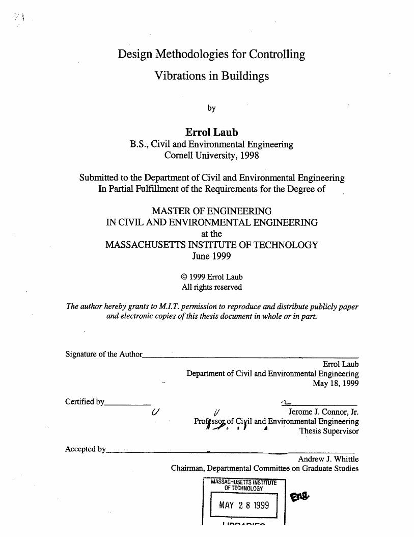
Signature of the AuthorErrol Laub
Department of Civil and Environmental EngineeringMay 18, 1999
Certified b y 6// Jerome J. Connor, Jr.
ProfsJ of Ciyil and Environmental EngineeringThesis Supervisor
Accepted by Andrew J. Whittle
Chairman, Departmental Committee on Graduate Studies
MASSACHUSETTS INSTITUffTEOF TECHNOLOGY
MAY 2 8 1999
LIBRARIES

Design Methodologies for Controlling Vibrations in Buildings
by
Errol J. Laub
Submitted to the Department of Civil and Environmental Engineering on May 18, 1999In Partial Fulfillment of the Requirements for the Degree of
Master of Engineering in Civil and Environmental Engineering
ABSTRACT
Although vibration absorbers have been employed in mechanical equipmentmounting for over 100 years, they have only recently been used for isolating large-scalestructures such as bridges and buildings. Their applications range from acoustic toseismic isolation of structures. Virtually any vibration magnitude can be prevented fromdegrading the performance of a structure. This thesis is intended to provide a practicalintroduction to the design and suitability of vibration isolators for various environments.It contains a discussion of the past, present and future of vibration isolation associatedwith buildings. Analysis and design examples are provided to illustrate the designmethodology.
Thesis Supervisor: Jerome J. Connor, Jr.Title: Professor of Civil and Environmental Engineering

Acknowledaments
I would like to first thank my wonderful family for bringing me to this stage in my life,
and for their unbelievably supportive attitude toward my education. This thesis is dedicated to
my exceptional parents Richard and Roselyn Laub, and my siblings Ethan, Asher and Abigail.
My thesis would not have been possible without the guidance of Professor Jerome J.
Connor, Jr. and Cheryl Sirna, both of whom helped me find the most important resources I
needed in order to complete this paper. In particular, I would like to give special thanks to
Professor Connor for his helpful input throughout the Masters of Engineering program, and for
the caring, thoughtful way he pushed me to discover more about the field of structural
engineering.
I am also very grateful to those friends at MIT who helped and encouraged me
throughout this project. I know how fortunate I have been to work with them over the past year,
and I wish them the best of luck in their future endeavors.
Page 3

Table of Contents
Abstract and Acknowledgments
Chapter 1: Introduction to Vibration Isolation of Buildings .................................... 7
Definition of Vibration Isolation and Problem to be Solved
Isolator Manufacturers and Examples of Isolated Structures
Chapter 2: Types of vibration isolators, and their uses ......................................... 10
Metal Spring Isolators
Elastomeric Isolators
Pneumatic Isolators
Chapter 3: Vibration Measurement and Design Issues for the Engineer ..................... 16
Vibration Measurement
Suggested Overall Acceptance Levels of Vibration
Steps of Vibration Isolation Design
Simplifications for Single-Degree-of-Freedom Systems
Rubber Bearing Models
General Applicability of Base Isolators
Chapter 4: Examples of Isolation Design Problems ........................................ 28
Design of Metal Spring Isolator
Design of Fabreeka Isolator
Design of DIS Isolator
Chapter 5: The History and Future of Vibration Isolation ......... .......................... 38
References ................................................... 44
Appendix Ia
Appendix Ib
Page 4

List of Figures
Chapter 1
Figure 1
Figure 2
Chapter 2Figure 3Figure 4Figure 5
Figure 6Figure 7
Chapter 3Figure 8
Figure 9
Figure 10Figure 11
Figure 12Figure 13
Typical vibration isolators ................................................ 8DIS Seismic Isolator ................................................ 9
Typical Metal Spring Isolator .......................................... 11Typical Elastomeric Isolator ............................ ............12Isolation properties and transmissibility of Nitrile, for variousfrequencies ................................................................ 13Typical Pneumatic Isolator ............................................ 14Schematic of typical Pneumatic/Elastomeric Isolator ............... 15
Single-Degree-of-Freedom system undergoing externalloading ........................................... ..........................21Single-Degree-of-Freedom system undergoing supportexcitation .................................................................. 22Model of isolated mass with internal stiffness and damping ....... 22Model of Natural Rubber isolator under horizontal excitation.....23Model of Lead Rubber Bearing ........................................ 25Radius-of-gyration isolator configuration ............................ 26
Chapter 4Figure 14 Metal Spring Isolator configuration supporting industrial
machine ......... ............................ ........... 28Figure 15 Design charts for Metal Spring Isolators ............................. 30Figure 16 TF versus Graphs of Frequency Ratio ......... 1...........31Figure 17 Graph of X-direction Motion versus Frequency Ratio ............. 32Figure 18 Skid supports for industrial machine .................................. 33Figure 19 Example building requiring seismic isolation ........................ 35Figure 20 First mode shape of example building ................................ 36Figure 21 Time-history displacement comparison of basement and fourth
floor .......... ............................................................. 37Figure 22 Structural control algorithm .................................... 38
Chapter 5Figure 23Figure 24Figure 25Figure 26
Active Mass Damper used for controlling building motion ....... 39Schematic diagram of Variable Hydraulic Damper ................. 41Electrorheological Fluid Isolator ........................................ 42Diagram of Magnetorheological Fluid Damper ....................... 43
Page 5

List of Tables
Chapter 3Table 1
Table 2Table 3
Chapter 4Table 4
Common Vibration Sources ............................................. 16Suggested Overall Acceptance Levels of Vibration ................. 18Typical damping factors of several soils .............................. 20
Comparison of fixed-base and base-isolated building models.....37
Page 6

Chapter One: Introduction to Vibration Isolation of Buildings
Definition of Vibration Isolation and Problem to be Solved
All structures are subject to vibration. The vibration isolator is a device that is designed
to effectively isolate such structures from harmful vibrations. A device's ability to isolate is a
result of its ability to temporarily store energy and release it at a later, less time-critical moment.
The most basic isolation system consists of an excitation source attached to a receiver structure
through an isolation element, such as a rubber bearing or metal spring.
Two important components of isolation are motion isolation and force isolation. In
isolation of motion, the engineer attempts to reduce stresses and deflections in the system in order
to create a comfortable working environment in a critical area (for either humans or machines).
In isolation of forces, the engineer concentrates on reducing the forces transmitted by the source
to a critical area in order to avoid the structure itself having to absorb the transmitted force.
[Fabreeka]
The list of isolator applications in building vibration control is endless. Vibration
isolators are used to decrease the annoyingly large vibrations of forge machinery that disturb
neighbors. They are used to decrease vibration originating from subway traffic that enters
through the basement of buildings and disturbs sensitive laboratory equipment. The devices are
also used to protect historic buildings from earthquakes. In each case, engineers must custom-
design a solution to the particular levels and distribution of unwanted vibration.
Isolator Manufacturers and Examples of Isolated Structures
The range of isolator manufacturers is almost as broad as the field itself. Companies like
Fabreeka, Vibro/Dynamics, Lord Corporation, and Kinetics manufacture numerous kinds of
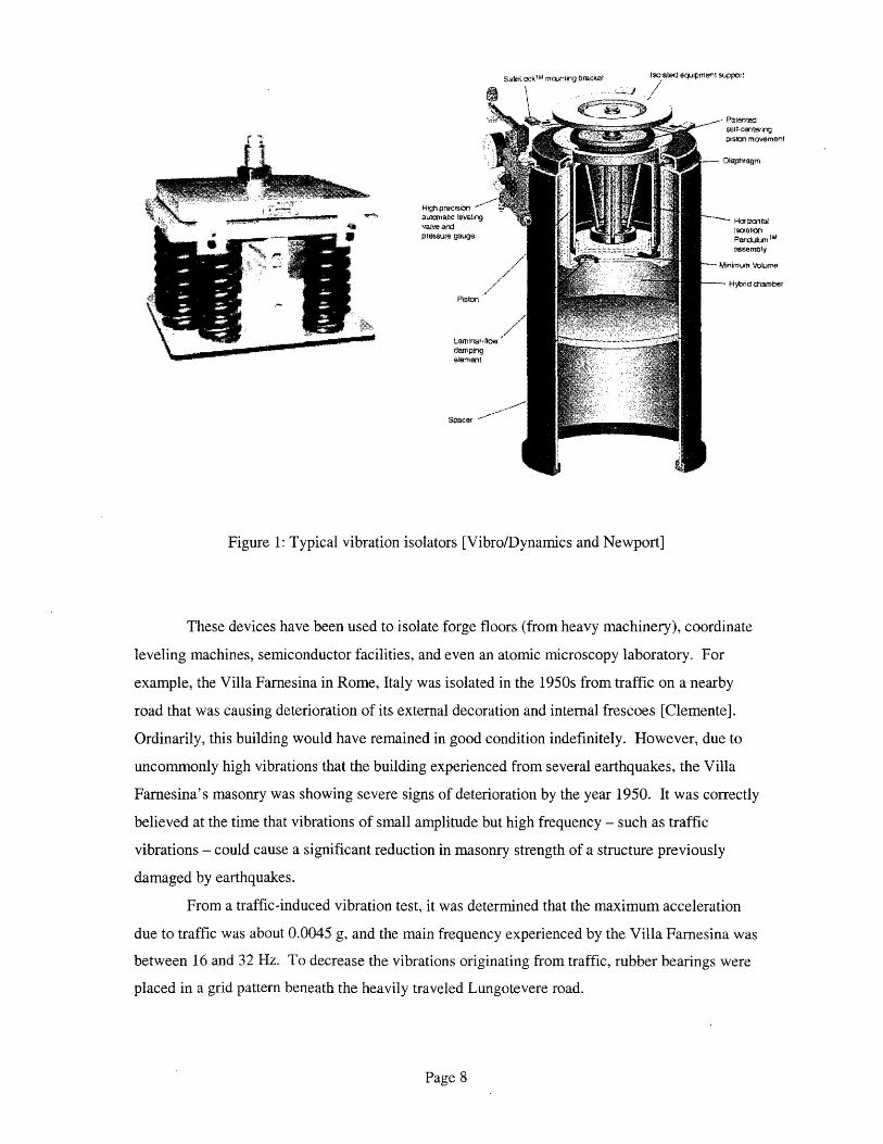
isolators for industrial applications. Figure 1 shows a few of the many models available.
Page 7
Salei.ckl'4
mrA.nteg ' acket I aaled eqi pment suppor
,Id i ,n ,,,,-. :;,I~~~~~~~
High precson -aurtie ievelingwatve arsd
aarnrt aptesu. guge
Laitrt
element
Spacer -
Figure 1: Typical vibration isolators [Vibro/Dynamics and Newport]
These devices have been used to isolate forge floors (from heavy machinery), coordinate
leveling machines, semiconductor facilities, and even an atomic microscopy laboratory. For
example, the Villa Farnesina in Rome, Italy was isolated in the 1950s from traffic on a nearby
road that was causing deterioration of its external decoration and internal frescoes [Clemente].
Ordinarily, this building would have remained in good condition indefinitely. However, due to
uncommonly high vibrations that the building experienced from several earthquakes, the Villa
Farnesina's masonry was showing severe signs of deterioration by the year 1950. It was correctly
believed at the time that vibrations of small amplitude but high frequency - such as traffic
vibrations - could cause a significant reduction in masonry strength of a structure previously
damaged by earthquakes.
From a traffic-induced vibration test, it was determined that the maximum acceleration
due to traffic was about 0.0045 g, and the main frequency experienced by the Villa Farnesina was
between 16 and 32 Hz. To decrease the vibrations originating from traffic, rubber bearings were
placed in a grid pattern beneath the heavily traveled Lungotevere road.
Page 8
,- Patenteciselt-cenerJig>sm;n miovement
-- Diaphragm
"" HarizctadliseatlonPerndulum Masemrnty
Minimum VaTome
--- Hybrid chamber
C 'z

In earthquake isolation applications, large DIS (Dynamic Isolation Systems) isolators
have been used to isolate entire buildings and bridges. The DIS isolator is shown in Figure 2.
Figure 2: DIS Seismic Isolator [DIS]
This isolator has been used to protect many types of structures, including San Francisco and
Oakland City Halls, and Stanford's Linear Accelerator Center. Although the field of seismic
isolation is barely several decades old, there are several manufacturers of seismic isolator
bearings in the U.S., and the industry is growing rapidly.
Page 9

Chapter Two: Types of Vibration Isolators and their Uses
There are many different kinds of vibration isolators currently on the market, but the
three most common are metal spring isolators, elastomeric isolators, and pneumatic isolators.
Each of the three has advantages over the others for certain applications and frequency ranges.
Other materials used for isolation are felt, cork, fabric and wool. These materials are used when
the device must be very stiff.
Metal Spring Isolators
These devices are effective for vibration frequencies between 1 and 8 Hz [Bachmann],
and have been used for industrial machinery for over 100 years [Fabreeka]. They act as isolators
through their stiffness alone, since metal as a material does not provide damping. This means that
metal spring isolators can only be designed for a single forcing frequency, and will not be
effective if the forcing frequency changes. For this reason, isolator manufacturers often install
separate damper parts into metal spring devices to artificially provide damping. Helical metal
springs are effective even in spatial isolation, and can therefore be used in cases where
unbalanced rotating masses produce low-frequency excitation. However, slender helical springs
are sometimes lacking in global stability, and engineers must carefully consider the flexibility of
the isolator in all directions before finalizing a design. This concern is particularly prevalent
when low frequency isolation is required. Figure 3 shows a typical metal spring isolator.
Metal spring isolators have several disadvantages when compared with elastomeric
isolators, however. Sound is transmitted well through a metal spring isolator, and therefore
unwanted acoustic vibrations are still transmitted to the receiver. Metal spring isolators only
provide stiffness, as noted above, and do not provide damping.
Metal spring isolators, however, have several advantages over elastomeric isolators.
They are relatively ductile; they perform well even under large deflections. In many cases, they
also perform well under wide temperature extremes. Metal isolators do not have a tendency to
drift, or continuously deflect, under dead loads. For this reason, as well as several others, the
characteristics of metal spring isolators can be predicted almost exactly.
Page 10

Figure 3: Typical Metal Spring Isolator [Vibro/Dynamics]
Elastomeric Isolators
The term "elastomeric" refers to rubber as an isolating material. These isolators are also
over 100 years old, and have been used in high-frequency applications (from 5 to 20 Hz)
[Bachmann]. Figure 4 shows a typical elastomeric isolator.
Rubber vibration isolators were almost always made from natural rubber before World
War II, and although during the War synthetic rubber isolators were developed, natural rubber is
still the most widely used in elastomeric isolators [Crede]. Some of the synthetic rubbers that
have been successfully used in vibration applications are Buna N, Nitrile, and Neoprene. Buna N
and Neoprene are especially satisfactory in high-temperature operation, as they deteriorate more
slowly than other rubbers at high temperature. Neoprene and natural rubber both withstand static
loads at room temperature without much drift or creep, and Buna N is extremely good for
resisting drift at high temperature.
Page 11
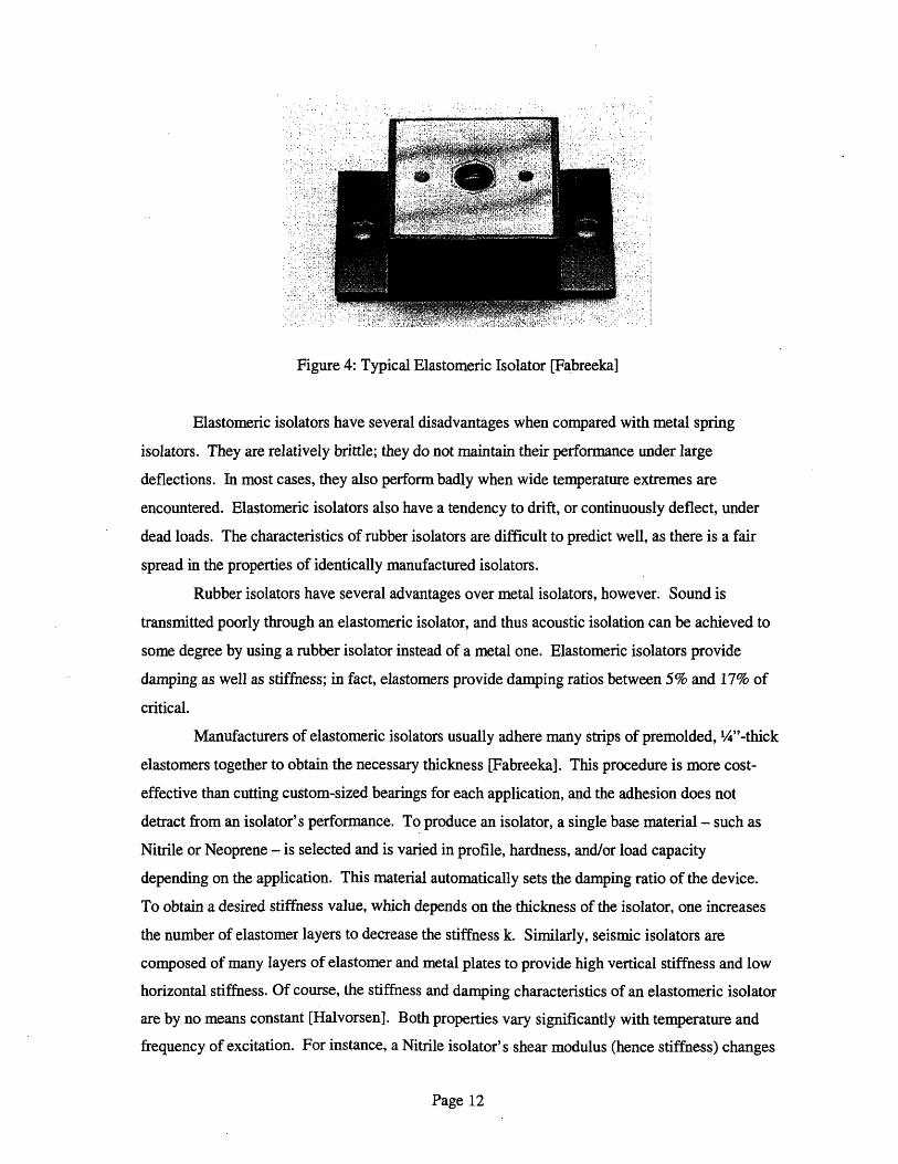
Figure 4: Typical Elastomeric Isolator [Fabreeka]
Elastomeric isolators have several disadvantages when compared with metal spring
isolators. They are relatively brittle; they do not maintain their performance under large
deflections. In most cases, they also perform badly when wide temperature extremes are
encountered. Elastomeric isolators also have a tendency to drift, or continuously deflect, under
dead loads. The characteristics of rubber isolators are difficult to predict well, as there is a fair
spread in the properties of identically manufactured isolators.
Rubber isolators have several advantages over metal isolators, however. Sound is
transmitted poorly through an elastomeric isolator, and thus acoustic isolation can be achieved to
some degree by using a rubber isolator instead of a metal one. Elastomeric isolators provide
damping as well as stiffness; in fact, elastomers provide damping ratios between 5% and 17% of
critical.
Manufacturers of elastomeric isolators usually adhere many strips of premolded, /4"-thick
elastomers together to obtain the necessary thickness [Fabreeka]. This procedure is more cost-
effective than cutting custom-sized bearings for each application, and the adhesion does not
detract from an isolator's performance. To produce an isolator, a single base material - such as
Nitrile or Neoprene - is selected and is varied in profile, hardness, and/or load capacity
depending on the application. This material automatically sets the damping ratio of the device.
To obtain a desired stiffness value, which depends on the thickness of the isolator, one increases
the number of elastomer layers to decrease the stiffness k. Similarly, seismic isolators are
composed of many layers of elastomer and metal plates to provide high vertical stiffness and low
horizontal stiffness. Of course, the stiffness and damping characteristics of an elastomeric isolator
are by no means constant [Halvorsen]. Both properties vary significantly with temperature and
frequency of excitation. For instance, a Nitrile isolator's shear modulus (hence stiffness) changes
Page 12
I-:. i: r··;: · :: :
:··.i1
: -· ··

by a factor of 20 over a temperature range from-7 to 49°C when subjected to 1000 Hz excitation.
At 1 Hz, however, Nitrile's stiffness has no significant variation with temperature. Loss factor,
an indicator of the damping value, is almost a factor of 10 greater for Nitrile at 1000 Hz than at 1
Hz. See the left side of Figure 5 for the variation of Nitrile stiffness and damping values for
various temperatures.
Displacement transmissibility is simply the ratio of vibration amplitude at the receiver to
the amplitude at the source. When transmissibility is low - certainly less than one - the isolator
is performing well for the particular situation. For means of design, the displacement
transmissibility of an isolator is plotted for various temperatures versus frequency, as shown in
the right chart of Figure 5. This gives the engineer a feel for the behavior of a particular isolator
in a given configuration. This graph also helps the engineer understand how the isolator will
react when ambient temperature is altered.
I Fig Dynamic material properties for nitriteL rubber.L
11II
II,-J
ioI
lit
I ,
4 ........
-I.*1
.1
.31JI,-2
4 A U ti 1s 11 in mTrepwtu (F) ,6 _._...........
I' I , ' I , 1 * 1 ' I I ,.
V M#. Al- SO A. SO 7- .2-. i
l - - - - - -. ' L*A SJI
i
1I
ilISfi$¢is(
I. E. lf I
Frequfny Hz
Figure 5: Isolation properties and transmissibility of Nitrile, for various frequencies [Halvorsen]
Page 13
le4
le'
L..iZ.
c
-
zL
-aZI11L
i
i
I
i
iI
.i
iI
.................... &ll I L L 1l
I_,.[ . . . . . . .. l. . r. I I i . . ... I . . . . . . . . .I , ' I i'
!
i
I=:
11a
I_

Pneumatic Isolators
"Pneumatic" denotes an air spring, and these isolators are used especially for low
frequency forcing of 0.4 to 5 Hz (or large shock displacement) [Fabreeka]. Figure 6 shows a
typical pneumatic isolator.
Pneumatic isolators are used for many different applications, including vehicle
suspensions, coordinate measuring machines, electro/optical instruments and precision machine
tools. They are usually at least semi-portable, and thus an engineer may decide to consider
several uses for the isolator over its lifetime. Pneumatic isolators are precision equipment, and
are increasingly being used in many different industries.
In some cases, an engineer may decide to combine two or even more types of isolators to
create a composite that has advantages over each of its separate components. Figure 7 is an
example of an isolator with pneumatic and elastomeric components.
* WG-C4'VO TC;A' DRCs! LL' .t T': ; . SLAO 2 .
Figure 6: Typical Pneumatic Isolator [Fabreeka]
Page 14

TYPICAL- EQUIPMENT
INTERFACE
AIR CHAMBER
AIR INLET'- -- FOR
DAMPING FLUID
PNEUMATICIELASTOMERIC ISOLATOR WITH DAMPING
Figure 7: Schematic of typical Pneumatic / Elastomeric Isolator [Fabreeka]
Page 15
I
I
r'25E--1t=.I-SIF, "A-ESM -

Chapter Three: Vibration Measurement and Design Issues for
the Engineer
Vibration Measurement
Table 1 lists some of the more common sources of vibration, and the frequencies and
amplitudes - in inches or % of gravity - of the excitations [Fabreeka].
Sources
Air Compressors
Handling Equipment
Pumps
Building Services
Foot Traffic
Acoustics
Air Currents
Punch Presses
Transformers
Elevators
Railroad
Highway Traffic
Earthquakes
Nuclear Detonations
Frequency (Hz)
4-20
540
5-25
7-40
0.5-6
100-10000
Various
Up to 20
5-400
Up to 40
5-20
35 MPH
03-8
0.3-8
Amplitude (in. or % gravity)
102
10- 3
10-3
10 '4
Various
Various
10 5 - 10-2
10-5- 10 -4
o10-- 1o-0' 3
+/- 0.15 g
+/- 10 3 g
0.5 g
0.5 g
Table 1: Common Vibration Sources [Fabreeka]
As any vibration consultant knows, there are numerous possible sources'of vibration that
should be considered when isolating any part of a building. Some of the most notable sources are
written in the table above in bold lettering. Foot traffic, elevators and highway traffic near a
building are especially important to notice where sensitive laboratory equipment is concerned.
Recognizing the source(s) of vibration that excites a structure is not the only variable in isolation
Page 16
-

design, however. The distance between a structure and the source of the excitation(s) it is
subjected to plays an extremely important role as well, since vibrations will usually attenuate
(decrease in amplitude) over a short distance. Since no hard-and-fast rules exist for estimating
the frequency or magnitude of vibrations a structure will experience by knowing the sources of
vibration, vibration consultants always use portable measuring equipment to measure the level of
vibration in key areas around the site in question. These surveys can determine considerable
information about the excitation, including:
1. the direction of the vibration source,
2. the amplitude of vibration to see if it exceeds the sensitivity level required by the equipment
or area to be isolated, and therefore the engineer can decide whether isolation need be
considered at all,
3. the Power Spectrum Density of the source,
4. the effectiveness of the isolator, since the "floor" vibration can be compared with the isolated
system.
Besides this extensive measurement survey of existing vibrations, the vibration
consultant must also take measurements outside the everyday range of excitations, since the site
is likely to experience unexpected vibrations - such as beat frequencies and shock pulses -
frequently. To measure these vibration levels, an artificial excitation must be created using
actuator devices to simulate these unexpected loads, and measuring equipment can then be used
to determine the resulting vibration levels.
Suggested Overall Acceptance Levels of Vibration
A generalized guide to the acceptance levels of several environments is presented in
Table 2 [Bachmann]. These vibration levels are not necessarily required according to law, but are
global criteria derived from engineering experience and knowledge of the acceptable vibration
levels stated in numerous building codes.
Page 17

Environment Acceptance Level
Pedestrian structures a < 5 -10 % g
Office buildings a<2%g
Sports hall a < 5 - 10 % g
Dancing/Concert halls a < 5 - 10 % g
Factory floors v < - 10 mm/s
Table 2: Suggested Overall Acceptance Levels of Vibration [Bachmann]
Vibration tests on people have concluded that a vibration amplitude of 0.001 inch (0.1
mm.) is easily detected by office employees while working. This suggested acceptance level
requires that floor deflections in office buildings also be limited due to vibration acceleration
considerations.
Another consideration that enters the design of a building is that building damage will
often occur when either large amplitudes or frequencies of excitation - or both - are experienced.
Damage will probably occur when the vibration frequency is 8 Hz and the amplitude is 3900
microinches. Another damaging combination is 100 Hz and 400 microinches.
Stating vibration acceptance levels in terms of acceleration and velocity units may be
convenient for the purposes of determining the need for isolating a structure, but once it has been
decided to use vibration isolators in a design, the vibration's frequency becomes extremely
important. This is because excitation frequency determines the type of isolator to employ in a
design, as noted earlier.
To illustrate how frequency is used to determine acceptable vibration levels, let us
consider an office building environment. The primary vibration of concern in an office building
is foot traffic, unless the building is slender - in which case wind becomes a consideration - or
unless vibration-sensitive equipment or other special cases are present. If a building structure is
composed of materials that have natural frequencies at or near the walking pace of employees, the
building's floors will probably vibrate in an uncomfortable way. Fortunately, this is almost never
the case. The walking rate for most people is around 2 Hz, while concrete and steel floor systems
usually have much higher natural frequencies. For the rare case that the walking rate reaches
more than 2.4 Hz, the fundamental frequencies for floors should comply with the following
guidelines:
Page 18

· reinforced concrete: f > 7.5 Hz
· prestressed concrete: fi > 8.0 Hz
· composite (in-situ concrete slab on steel): f1 > 8.5 Hz
* steel (corrugated sheets with concrete infill: f, > 9.0 Hz
Massive concrete members often perform well even with fundamental frequencies below
these suggested values, but they usually have frequencies above 7.5 Hz in any case. For special
sensitive cases, the frequency bounds suggested above probably need to be raised.
Steps of Vibration Isolation Design
Vibration Control Engineering consists of five basic steps [Bramer, et all. They include:
1. Analyze the environment of the vibration source and receiver, and form a simple
mathematical model of the excitation properties.
2. Specify all of the design performance criteria, including vibration tolerance of the
environment requiring isolation.
3. Decide which isolation method is most appropriate for the problem.
4. Perform a theoretical analysis of the new (isolated) system's vibration performance using the
selected method.
5. Select an isolator product that meets the constraints imposed on the problem, including
available space, loading, fastening possibilities, stability, and visual appearance.
The first step in design - analyzing the vibration environment around the site - can easily
be taken to extremes if decisions are not made early in the analysis as to which sources are most
likely to have the most effect on the receiver structure. The environment surrounding the receiver
may actually provide substantial damping of its own, especially when vibrations are transmitted
to the receiver by the ground [Fabreeka]. Table 3 shows typical damping factors of several soil
types.
Page 19

Soil Type Damping Factor 5
Dry sand and gravel 0.03 - 0.07
Dry and saturated sand 0.01 - 0.03
Dry and saturated sand and gravels 0.05 - 0.06
Clay 0.02 - 0.05
Silty sand 0.03 - 0.10
Table 3: Typical damping factors of several soils [Fabreeka]
There are several characteristics that an isolator must have to perform adequately. It
must remain elastic over the life of the installation. Of course, it must be able to support both the
static weight and the unbalanced dynamic force of the unit or system it is isolating. The isolator
should also have a lower natural frequency than the excitation itself, otherwise the excitation may
actually be amplified in force and amplitude. An isolator's natural frequency in Hertz is
calculated according to the following relationship:
fn = 3.13*
where KD is the Dynamic spring rate in pounds/inch, and W is the static weight of the isolated
unit in lbs.
An isolator is more effective when its natural frequency is low. At the very least, it
should have a frequency such that the ratio of disturbing frequency to isolator natural frequency is
1.414 or '12.
The third step, deciding which isolation method is best for the particular application, may
be avoided altogether with thoughtful consideration of the problem situation. For instance, the
problem itself might be corrected by simply dynamically balancing the unbalanced machine or
device that is producing the disturbance. The speed of the unbalanced rotation might be reduced
without affecting the machine's overall performance, though this is also often unpractical. The
most effective alternative to isolation is relocation of the vibration source to another site that is far
enough from sensitive areas. This solution can only be effective if the unbalanced vibration is not
Page 20

harmful to the machine itself. Finally, one might modify the sensitive piece's response to
excitation by adding mass or increasing stiffness.
Simplifications for Single-Degree-of-Freedom (SDOF) Systems
There are two basic cases of excitation that may be encountered in an SDOF vibration
isolation problem [Connor]. The first involves external periodic forcing, while the second
involves support motion.
In the first case, an isolator is used to isolate the support from the external excitation.
This case can apply to an unbalanced machine that disturbs employees in a laboratory. Figure 8
is a schematic diagram of an unbalanced machine of mass m that produces a periodic load p and
moves a varying distance u. An isolator is modeled as a spring of stiffness k, and a damper of
damping c.
c
/
Ii
k
mp,u
Figure 8: Single-Degree-of-Freedom system undergoing external loading [Connor]
In this diagram, p = posin&2t and therefore u = usin(at-8), where uo = Hl*pofk, H1 = ((1-
p2)2+(2tp)2)° s5, tan = 2tp/(l-p 2), and p = /co. The transmissibility or reaction force of the
support divided by p is called H3. The function H3 is calculated as follows:
H3= 1+ (2S) 2
= (1- 2) 2+ (2:p)2
One can see that for isolation to be effective (ie. H3 becomes less that one), the frequency ratio p
should be such that o < /12.
Page 21

In the second case, an isolator is used to isolate the machine from the support excitation.
This case can apply to sensitive coordinate measuring devices that must be isolated from floor
vibrations. Figure 9 is a schematic diagram of a machine of mass m that is excited by a periodic
load p originating at the support. For this case, the support moves a varying distance ug, and the
machine moves a corresponding distance ut. An isolator is again modeled as a spring of stiffness
k, and a damper of damping c.
C
/I,
/
/__. k
m
Ut
Figure 9: Single-Degree-of-Freedom System Undergoing Support Excitation [Connor]
In this diagram, H3 = uo/ugo, where uto is the amplitude of support motion, and ugo is the
resulting amplitude of machine motion. One can see that in both cases, the period of the isolator
should be less than the period of forcing.
In many instances, an isolated system is composed of a mass that itself has stiffness and
damping, and this member is attached to an isolator that has mass mf. Figure 10 shows a diagram
of this model:
Ch C
/ isolator
kb
mf
K
mU+ub+Ug
UblUg
Figure 10: Model of isolated mass with internal stiffness and damping [Connor]
Page 22
n-l_- L-J...
-�I-
.~~~~~~~·
The equations of motion for an isolated machine that itself has a stiffness and damping
quantity are:
md2u/dt2 + cdu/dt + ku = -m(d2ub/dt2 + d2ug/dt2)
and
mfd2ub/dt2 + kbub + cbdub/dt = ku + cdu/dt - mfd2ug/dt2
These equations use ug which is the displacement of the ground, ub which is the displacement of
the isolator, and u which is the displacement of the mass. For this isolator model, kb is designed
to be much less than k. If the isolator moves with a displacement amplitude ubo approximately
equal to ugo, u will be much less than the support displacement ugo, and isolation will be almost
perfect. In general, the frequency ratio is taken as approximately three, corresponding to an
equivalent period of three times the period of excitation.
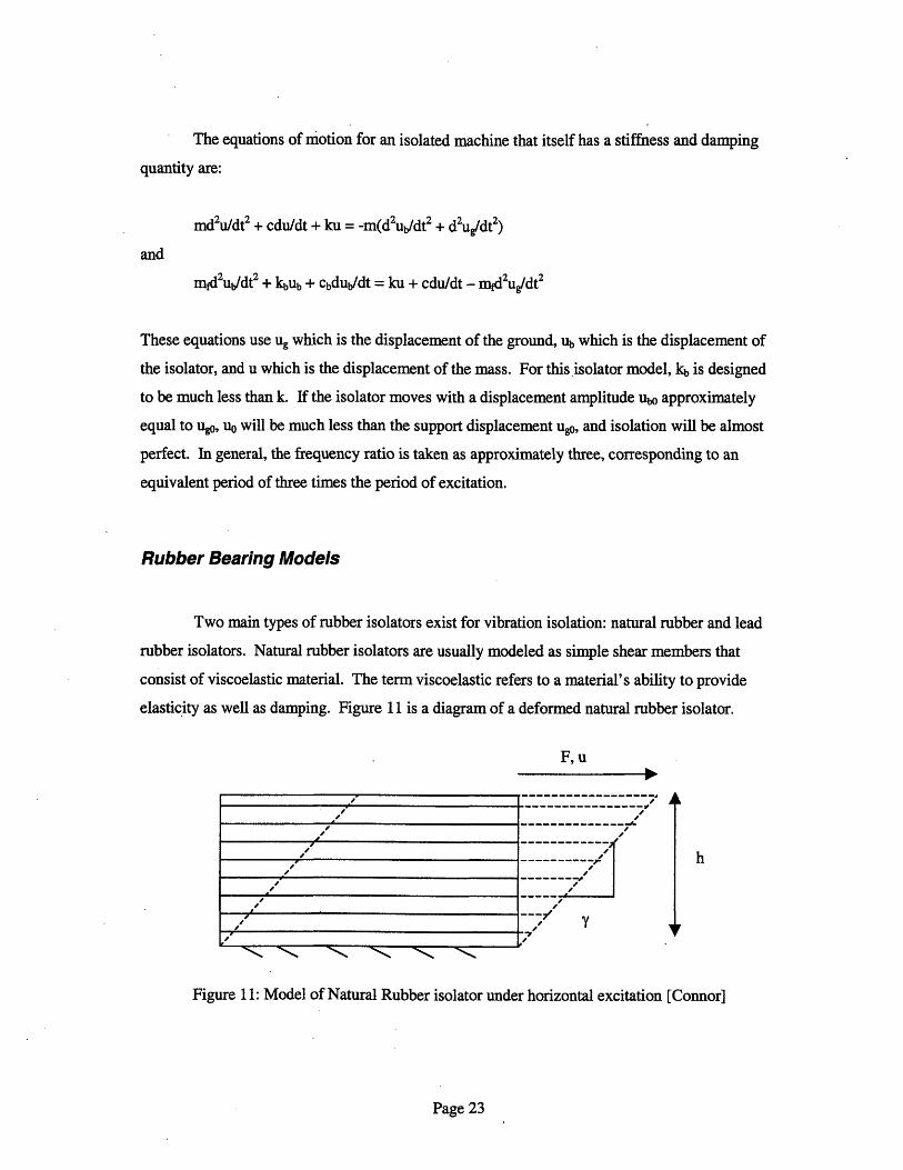
Rubber Bearing Models
Two main types of rubber isolators exist for vibration isolation: natural rubber and lead
rubber isolators. Natural rubber isolators are usually modeled as simple shear members that
consist of viscoelastic material. The term viscoelastic refers to a material's ability to provide
elasticity as well as damping. Figure 11 is a diagram of a deformed natural rubber isolator.
F, u
AL
h
Figure 11: Model of Natural Rubber isolator under horizontal excitation [Connor]
Page 23

From the above figure, y = u/h, which means that for a periodic loading that deforms the
beating as u = uosinfŽt, the strain deformation is y = yosinit. The forcing F = kqu + ceqdu/dt - ke
and ceq are the equivalent stiffness and damping of the device, respectively - and the force
required to deform the bearing uO is F = fdGsuo(sinit + rlcosQ2t), where fd = bearing area divided
by h, and Gs and rl are material properties. uo is simply defined as yoh, or the strain deformation
amplitude times the isolator height.
The equivalent stiffness keq is defined as:
kq tfd l ( -in G ()
and the equivalent damping ceq is simply a constant a times kq, where a depends on Gs and the
excitation frequency Q.
A lead rubber bearing (abbreviated LRB), on the other hand, is modeled as two distinct
elements: the elastomeric element which is assumed linear elastic, and a lead plug which is
assumed elastic-perfectly plastic. A diagram of this type of bearing can be found in Figure 2 (the
DIS lead-steel-rubber isolator). The plug shear stiffness is found from the formulas F/A = Gy and
T = ku where y = u/h. Thus, k2 = AG/h in the shear (or transverse) direction. k is typically one-
tenth of k2, where
k = fd EGs (QŽ)
N is the number of different material properties that cover the usual range of strain amplitude and
frequency, fd is A/h, and Gs is again a material property. The model for a lead rubber bearing is
shown in Figure 12:
Page 24

/
/
k2
kl
F,u
Figure 12: Model of Lead Rubber Bearing [Connor]
The equivalent stiffness keq is defined as:
where and are material properties, and N is defined as before for the natural rbber isolator.
where k and i are material properties, and N is defined as before for the natural rubber isolator.
The equivalent damping cq is related to the excitation frequency and the material properties k,
and ri as follows:
N
EQik (P (7ii)C =Ceq N
i=1
General Applicability of Base Isolators
Base isolators are used to isolate a structure from its base vibrations, be they seismic,
acoustic, or another type of excitation [Fabreeka]. There are several considerations one must take
into account before installing a base. isolator:
* If a base isolator isolates a structure from the ground itself, subsoil conditions must be
investigated to ensure that the ground will not input long period vibration into the isolated
Page 25
-

structure above. If the ground has a low equivalent stiffness value, the isolators may actually
amplify the ground motion and the structure then shakes uncontrollably.
* The structure together with the isolators beneath it must have a height-to-width ratio that
prohibits overturning of the system. The problem of overturning is significant for designing
isolators, since isolators are usually weak in vertical tension. If a structure pulls upward on
an isolator, the isolator will almost surely fracture.
* Another important consideration is that the site allows the base to move an even greater
distance than the isolator has been designed for. If the site has not been prepared for the large
deformations the structure will undergo, the structure may disturb its surroundings.
* A final consideration is that there be little lateral loading on the structure - no more than 10%
of the structure' s weight.
A few comments about the problem of overturning are in order. There are three types of
possible isolator configurations that can be used for base isolation [Encyclopedia]. They are
called the Underneath Mounting System, where isolators are mounted beneath the structure;
Center-of-gravity System, where the isolators are placed in the plane of the structure's centroid;
and Radius-of-gyration System, where the isolators are mounted on both sides of the structure as
shown in Figure 13.
E ,:
~'"~:.
Figure 13: Radius-of-gyration. .isolator configuration [Encyclopedia]
Figure 13: Radius-of-gyration isolator configuration [Encyclopedia]
Page 26
::·:�
:·::
.·
· ····
,·
For the Underneath Mounting System, in general, the isolators that resist overturning
should be spaced a minimum of twice the height of the center of gravity of the structure above the
isolators. In the Center-of-gravity System, two conditions that must be met are: 1) the isolators
that resist overturning should be spaced a minimum of twice the structure's radius of gyration,
and 2) the horizontal stiffness of the isolators should be the same as the vertical stiffness. The
ratio of height to width of the structure must be less than 2.8 for this system to perform well. For
the Radius-of-gyration System, the height to width ratio can be up to 5. The main concern that
must be addressed with this system is that a low rigidity may allow bending to occur between the
upper and lower isolators.
Page 27

Chapter Four: Examples of Isolation Design Problems
Design of Metal Spring Isolator
The following example illustrates how a metal spring isolator is designed, assuming no
damping is used [Crede]. An unbalanced industrial machine transmits large vibrations to the
floor beneath, and it is decided to reduce the vibrations by placing isolators at both ends of the
two beams supporting the machine. See Figure 14 for a diagram of the isolator configuration.
/
r=1 .
N
N
I
plan
Fy
machine
a=-8
isolator centrolc
b=-30 b=30
elevation
Figure 14: Metal Spring Isolator configuration supporting industrial machine [Crede]
Page 28
,,
=- 1'

Fx, Fy and Fz represent the unbalanced forces transmitted in the x, y and z directions to
the support system by the machine. They are applied 4 inches above the centroid (denoted e), and
the isolators' mid-height is 8 inches below the centroid (denoted a). The machine and beam
system weighs 1000 lbs. The radii of gyration of the system through the centroid is px=9, py=8.5
and pz=6. The unbalanced force that must be absorbed completely by the metal spring isolators is
periodic with a frequency f = 8 cycles per second. This force is taken as acting in the x, y and z-
directions separately; thus, vibrations in the three directions are independent for design purposes.
To begin the design, one can form dimensionless ratios which facilitate the calculation of
the isolators' required natural frequencies:
e/pz = 0.667 EIPx = 0.444
a/pz = -1.333 a/px = -0.889
b/pz = +/-5 c/p, = +/-1.333
a2 /pz2 = 1.78 a2 /px2 = 0.79
b2/pz2 = 25 C2 /px2 = 1.78
npz2/b2 = 0.04 npx2/c2 = 0.561
The next step is to find all natural frequencies of the machine-and-beams configuration.
To determine the system's natural frequencies in terms of its vertical natural frequency Qy, one
can use the chart on the left side of Figure 15 to find the two possible frequency ratios (the
rightmost side of Figure 15 shows a design chart for a single-DOF system). The equation plotted
in this chart is:
QC P _ 1 (1+ a )+l _ (+ 2 ) +1 -4nP2 zy xb - b2 (1+ z)+l+ I (+ -zhjb2This equation uses n which is defined as kx/ky. Consequently, one calculates the quantity pz/b*
kx/ky which in this case is 0.2 for the z direction. Using a/pz = -1.333, (c/&2y)(pz/b) = 0.19 or
1.03. As can be seen from the above equation, the sign of a/pz does not affect the natural
frequencies on the left side. However, the sign of b/pz should be the same as the sign of the
radical on the right side of the equation. This procedure conveniently makes the frequency ratio
Qc/Qy positive. If pA/b = +0.2, 2c/Qy = 0.96 and 5.15. Calculating p,/c*4 kx/ky, one gets 0.75
Page 29

in the x direction. Since a/px = -0.889, (2c/Qgy)(pxIc) = 0.57 and 1.29. This returns Qc/Qy =
0.76 and 1.72.
x
.3
eIc
.C,I
Eo
SINGLE-DEGREE-OF-FREEDOM SYSTEM
5,000
3,000dr 2,000
100025
E l.OO
,vv
30C
20C
//10 20 30 50 uuw -u jw J -, ,w
Weight of mounted body, lb
Dimensionless ratio b i¥'I, i
Figure 15: Design charts for Metal Spring Isolators [Crede]
The natural frequency in rotation about the y axis can be found from the following
equation:
QB In(b 2+C2 )=
2
where Qy = /(4ky/m) is the vertical, axial natural frequency of the machine system. This formula
gives QB/Q2y = 3.8. We thus have six natural frequencies for the system: vertical (Qy), coupled in
the x direction (0.96Qy and 5.15 y), coupled in the z direction (0.76Qy and 1.72 Qy), and
rotational about the y axis (3.8 Qy).
Page 30
39
tnn--
, I'
f
-- 74--f
/l¢~. fA}
., , i,
r0C L//_~_/ ,/ . ? ./ / /. 41 /I/ //11 I I
.1 X,I.1
Ln-z
II
_.,w, - -.._ -^ iniV -- 1- I M
4y
c'
l . . . . I . _ _ . , _ _. _ ... . . IA s
-P.
I ! fI
.E,
.J
_SP
Yivl I J I i III
w - ,u I
0o

The final step is to find a frequency ratio O/Qy that avoids all six natural frequencies by
examining the graphs of frequency ratio versus force transmissibility (TF) and the natural
frequency of rotation. See the Appendix for a plot of force transmissibility versus natural
frequency. Figure 16 shows the graphs of frequency ratio versus TF and one can easily see that a
low transmissibility is achieved when o/g2 y - 2.5. This ratio also avoids the rotational frequency
ratio of 3.8, and thus 2.5 is an effective frequency ratio for the isolator design.
1 .
.0.5 . _ ____A,
Ea,
00Ls2
p0
J IIIA
I I I I I I I I I I . I
0.1 . , _ I 1.10;05 '
0.01I
O005 I I I I--l I I
0.0011 I - I _ . 1I -1 1 1 I.!0,1 0.2 0,3 0,5 1 2 3 5 10
Ratio urcing frequency w Natural frequency in Y direction )
...
.?
Ratio Forcing frequenc y Natural frequency in Y direcon fly
Figure 16: TF versus Graphs of Frequency Ratio [Crede]
Page 31
lu
. I 1
---- . -I

The desired vertical natural frequency of the isolators is 2*re*f/2.5 or 3.2 cycles per
second, where f is the excitation frequency of the machine. The stiffness required of the isolators
in all three directions is ky = fn2*W/(3.13) 2 or 262 lb./in., where fn is the desired natural
frequency of the isolators and W is the weight of the machine-and-beams assembly.
One can examine the effect of frequency on the location of the axis of rotation by plotting
lc/p versus the co/Qy ratio. The graph of the x-direction motion is shown in Figure 17 and in the
Appendix.
II'
0
.20_'a"01.01;
a.2M
Forcing frequency I it LNatural frequency in Y direction U I'1y
Figure 17: Graph of X-direction Motion versus Frequency Ratio [Crede]
Design of Fabreeka Isolator
The next example illustrates how a vibration isolator is designed, using an isolator
manufactured by Fabreeka. This example considers both the stiffness and damping properties
required for the isolator [Fabreeka].
The problem to be solved is: an industrial machine transmits annoying vibrations into its
elevated floor support, and thus it has been decided to isolate the machine from the floor. The
machine's weight is uniformly distributed and is 14,000 lbs., the speed is 45 Hz, and the
machine's support is stiff, since it rests close to a column support. The centroid of the machine is
in a stable location of the unit - it is not high on the unit and is near the geometric center of the
Page 32
-10
~ c In plane normal to Z axis
------- ------+5 ; In plane normal toXaxis
- In plane normal to Zaxis+20
2) A A t n 1 i
l.+;n
- v . 2
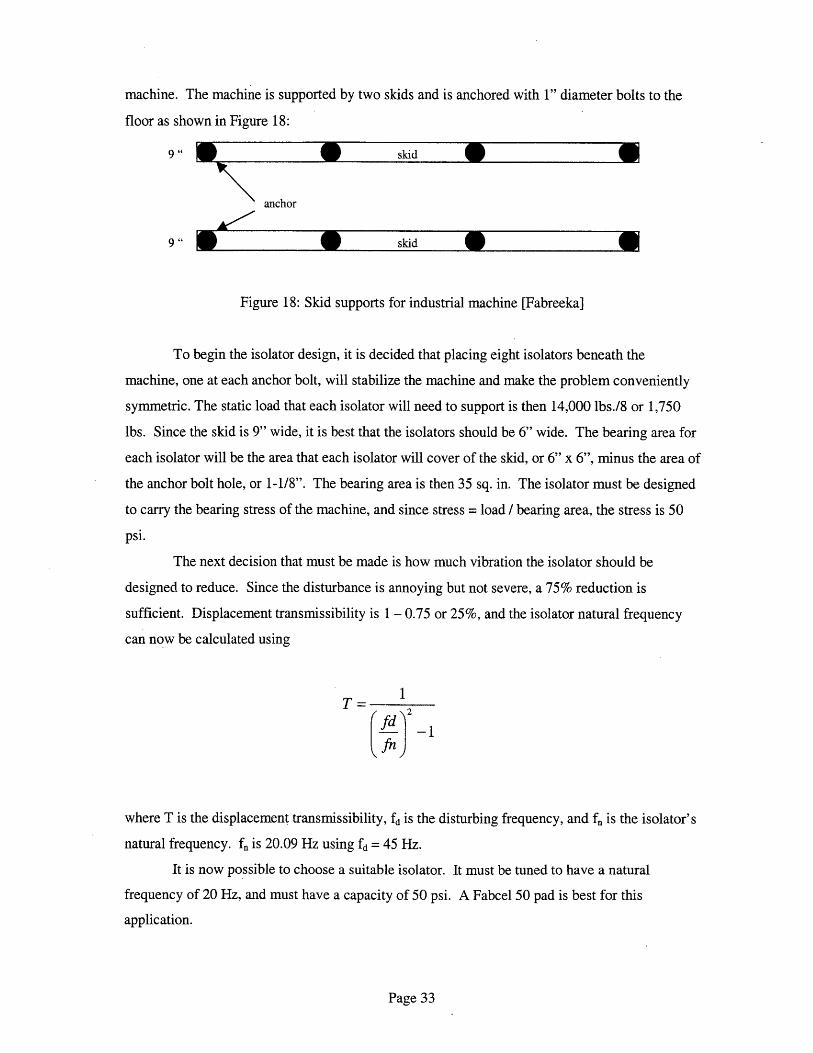
machine. The machine is supported by two skids and is anchored with 1" diameter bolts to the
floor as shown in Figure 18:
9" a * skid
anchor
9" skidGet
Figure 18: Skid supports for industrial machine [Fabreeka]
To begin the isolator design, it is decided that placing eight isolators beneath the
machine, one at each anchor bolt, will stabilize the machine and make the problem conveniently
symmetric. The static load that each isolator will need to support is then 14,000 lbs./8 or 1,750
lbs. Since the skid is 9" wide, it is best that the isolators should be 6" wide. The bearing area for
each isolator will be the area that each isolator will cover of the skid, or 6" x 6", minus the area of
the anchor bolt hole, or 1-1/8". The bearing area is then 35 sq. in. The isolator must be designed
to carry the bearing stress of the machine, and since stress = load / bearing area, the stress is 50
psi.
The next decision that must be made is how much vibration the isolator should be
designed to reduce. Since the disturbance is annoying but not severe, a 75% reduction is
sufficient. Displacement transmissibility is 1 - 0.75 or 25%, and the isolator natural frequency
can now be calculated using
1T=
where T is the displacement transmissibility, fd is the disturbing frequency, and fn is the isolator's
natural frequency. f is 20.09 Hz using fd = 45 Hz.
It is now possible to choose a suitable isolator. It must be tuned to have a natural
frequency of 20 Hz, and must have a capacity of 50 psi. A Fabcel 50 pad is best for this
application.
Page 33

One more step: since the machine anchors are 1" bolts, the Fabcel washer must match the
steel washer on the existing anchor bolts. The washer must have a 2.5" outside diameter, 1"
inside diameter, and be 5/16" thick. This completes the Fabreeka isolator design.
It is interesting to note that Fabreeka's design procedure requires two input values:
required isolator frequency and the bearing stress that will be carried by the isolator. In general,
there are ten pieces of information that must be known in order to select an isolator:
1. Amount of isolation desired, or transmissibility
2. Fundamental frequency of the excitation
3. Maximum load for each isolator, the weight distribution, and the location of the centroid of
the vibration source
4. Location and clearance around the isolator
5. Clearance around the receiver system
6. Height limitations
7. Support stiffness
8. Flexibility of plumbing, HVAC or other lines attached to the receiver structure
9. Allowable motion of the receiver (such as maximum acceleration)
10. Environmental conditions (such as temperature, radiation, etc.)
Design of DIS Isolator
This final example shows how a seismic isolator is designed, using a DIS (Dynamic
Isolation Systems) isolator. As already shown in Figure 2, this isolator contains elastomeric pads
separated by steel plates. DIS isolators usually contain lead cores which provide damping. The
main difference between seismic isolators and Fabreeka isolators is that seismic isolators are used
to isolate entire buildings instead of equipment. Seismic isolators are also designed to resist
horizontal, not vertical, vibrations.
The building to be isolated is shown in Figure 19. It is located in San Francisco, which
means that it must be designed to withstand the most severe earthquake possible. The building is
founded on clay and silt, and the structure is a steel eccentric braced frame. Since this building is
surrounded by taller buildings, wind speed and pressure are low.
Page 34

Figure 19: Example building requiring seismic isolation
The following assumptions are used for preliminary isolator design:
* Design Acceleration Level = 40% gravity (Zone 4 level earthquake, building is located >15
km from a fault)
* Soil Type = 2 (clay and silt)
* The structure is a steel eccentric braced frame: Rwi = 3 (Rwi is a reduction coefficient)
· Wind load is negligible, so lead cores do not yield due to wind
* Emce = 50% of Dead Load
· Isolators move together as a unit. This assumption requires that a rigid waffle slab be
designed for the basement to connect the isolators.
The preliminary design is performed using a program called ISOLATE created by DIS. The
preliminary design results for the isolators are as follows:
* Moat must be two feet wide to accommodate the isolator deformation.
* Each isolator is 39.5" in diameter and 14.5" in height
* For the lead core isolators, the cores are 6.5" in diameter.
* The vertical stiffness of the isolators is 18000 kip/inch.
Page 35

Lead-core isolators are placed on the perimeter of the building, and non-core isolators are
placed in the interior. The vertical stiffness of the lead-core isolators is 11.26 kip/inch, and
the vertical stiffness of the non-core isolators is 7.5 kip/inch.
Figure 20 shows the shape of the isolated building's first mode. It is apparent that the
building translates laterally as a rigid body. This is indeed what would be expected for the first
mode of an isolated, narrow building. The second mode is also a rigid body mode, but the
building translates longitudinally instead. The third mode is a rotational rigid body mode about
the building's center of mass. Thus, the base-isolated model behaves as expected.
Figure 20: First mode shape of example building
Once the mode shapes have been checked, the displacement histories of the basement
(Joint1298) and fourth floor (Joint2191) are compared, as shown in Figure 21. For the isolated
model, the graph shows that the two floors move almost perfectly together, and there is thus little
differential strain between floors.
Page 36
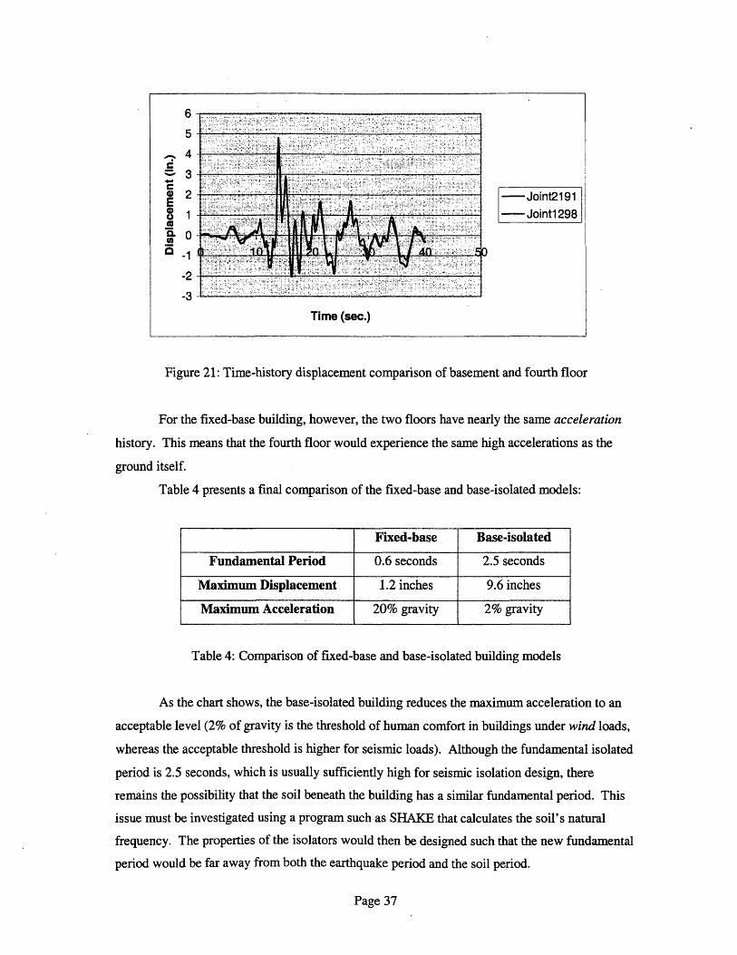
Figure 21: Time-history displacement comparison of basement and fourth floor
For the fixed-base building, however, the two floors have nearly the same acceleration
history. This means that the fourth floor would experience the same high accelerations as the
ground itself.
Table 4 presents a final comparison of the fixed-base and base-isolated models:
Table 4: Comparison of fixed-base and base-isolated building models
As the chart shows, the base-isolated building reduces the maximum acceleration to an
acceptable level (2% of gravity is the threshold of human comfort in buildings under wind loads,
whereas the acceptable threshold is higher for seismic loads). Although the fundamental isolated
period is 2.5 seconds, which is usually sufficiently high for seismic isolation design, there
remains the possibility that the soil beneath the building has a similar fundamental period. This
issue must be investigated using a program such as SHAKE that calculates the soil's natural
frequency. The properties of the isolators would then be designed such that the new fundamental
period would be far away from both the earthquake period and the soil period.
Page 37
5-
_ 4.
E
1
.-l -1
-2
-
Joint2191 !--- Joint1298
O
.::: . . - - V i: -. :- -. - ::-i .:-.: i:.::, .i .:i E .. - .:: . :.- - :. - ! .. :-- i :i p e. ::%:. :: :: :: ''::!:':.::i' .- -·: ·' : ' -:- .'''' : :''': : i: : S .: ::: i ::!i: '.'' :.. ' - f .:.:: .. :'" : ... :: : : ... ..:,i:: .: ,·:.-:---:' : ' ........... .:·:, .,.-.
.. : - '...; ;,, ..... . . . ...... ....
;. ,:;- :: : ,' ' .-- ::! l! ! :.:..- !'..!: .: :,: .,. :: ::::.;:>g: :.! ,!. ':' .::: !:: .. ,, :. :.-.., .,:::: .... :'·..
isi:',~i ;; ; ' ;i i ' I'[i ! ''' ''' '';!' ' ' i. ' ,; -'; . ii · ·:.: · · ·. " ! s i-. i' '
; i. '!. .: :'' *: ' ' '',' ::. :: :-:!. . ! !.W.'ii: ! i '' :: H ::!: ::: !: gt :: -.. : . .::.-: :::: ... ::. :.. > !;; ::!^. ::i': ,.!::'::: ::
: : : .: . :\ m . " -§ '-'" ................. :-"'!'''":!"!--"'- '" ''''~~~~~~~~~~~~~~~~~i:' .1:.:..:::!:!:::!:i: a-. ma..; i--.--. -.-. :.!:':':.
! : : ' ' E _ ' '' . I ! ; i . ' - A;' ! i : i '. ! '. '' J1 < s ' .................................................... l : '!:. . . .
~~~~~~~~~~~~ii Ig- , ; i ; i, .. v. > i ? -,, i . .j .: :ii:i~: i ': :: .siii~zj . !E-i . :
: .'-i;; .. . , . . :, , ,.'' '. ' .'i : - '' . '.'' ' -'':: .: '.'..' .. : ; :i'! :'i .'
:· .: · , ':: ·:'": :: :: s : --. : :: !: :- ; :. :. . ::!!:. .' . !::,:v.:: . :..· '. · :': --- :: :- - : -> !:::: ' -. : ;E . ':
Time (sec.)
Fixed-base Base-isolated
Fundamental Period 0.6 seconds 2.5 seconds
Maximum Displacement 1.2 inches 9.6 inches
Maximum Acceleration 20% gravity 2% gravity
11
Chapter Five: The History and Future of Vibration Isolation
Whatever the vibration problem may be, vibration control in buildings has emerged as an
exciting, rapidly developing specialty. Since the late 1800s, when vibration absorbers were used
exclusively in mechanical equipment mounting, isolator applications have been extended to
include structures ranging from microscopy laboratories on the atomic level to entire buildings on
the seismic level. The past decade, in particular, has featured the development and application of
seismic isolators to bridges and buildings.
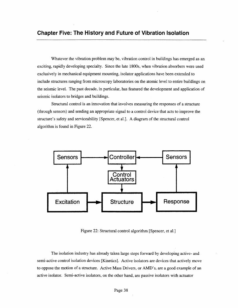
Structural control is an innovation that involves measuring the responses of a structure
(through sensors) and sending an appropriate signal to a control device that acts to improve the
structure's safety and serviceability [Spencer, et al.]. A diagram of the structural control
algorithm is found in Figure 22.
Figure 22: Structural control algorithm [Spencer, et al.]
The isolation industry has already taken large steps forward by developing active- and
semi-active control isolation devices [Kinetics]. Active isolators are devices that actively move
to oppose the motion of a structure. Active Mass Drivers, or AMD' s, are a good example of an
active isolator. Semi-active isolators, on the other hand, are passive isolators with actuator
Page 38

elements to change the properties of the isolators. Electrorheological - ER - and
magnetorheological - MR - fluid dampers are good examples of semi-active isolators.
Active-control devices are already used to control the motion of buildings and bridges,
such as the Nanjing Tower in China and the Rainbow Bridge in Japan [Spencer, et al.]. Both
AMD's - passive tuned mass dampers with actuator attached to an auxiliary mass - and hybrid
base isolators - passive base isolators with actuator supplements - are used worldwide. A
diagram of an AMD used in building motion control is shown in Figure 23.
Actuator// pr lng
I AMD LA
TMD
E--c_ _
Building
, Spring
Damper
Figure 23: Active Mass Damper used for controlling building motion [Spencer, et al.]
The auxiliary mass used in Active Mass Dampers is usually less than 1% of the total
structure mass, and is installed in one of the top floors of a building to resist the fundamental
mode of the structure. Hybrid base isolators, on the other hand, are placed in the basement of a
building. Since base isolators themselves decrease the interstory displacements as well as the
absolute acceleration of a building, active control is only needed to limit absolute base
displacement, and therefore hybrid base isolators cost approximately the same as passive base
isolators.
Whereas passive isolators maintain a constant set of isolation properties for any
excitation - such as stiffness and damping - semi-active isolators can "intelligently" alter their
properties for various vibration levels [Kinetics]. Before semi-active devices, engineers could
only design isolators for a certain predicted vibration environment. With semi-active isolators,
Page 39
L
/*

however, devices can change their own properties in response to changes in temperature,
frequency, or other important environmental parameters. Semi-active isolators are used primarily
for low frequency levels, since these are the most sensitive vibration levels for structures. These
isolators use sensors to determine how much vibration the isolator must absorb, and piezoelectric
actuators - devices that send electrical pulses in response to pressure changes - to change the
characteristics of the isolating material. Many semi-active isolators use three-dimensional
sensors to accurately interpret the vibration environment surrounding the receiver. Semi-active
isolators are already extensively used in Bose headsets for airplane pilots, certain types of
sensitive machinery, ductwork and loudspeakers. In particular, acoustic isolation is increasingly
becoming a semi-active control industry.
Variable Hydraulic Dampers, or VHD' s, are semi-active damping devices that can
change their own damping ratio through valve manipulation [Kurata, et. al.]. They consist of a
cylinder and piston, a flow control valve, check valves, and an accumulator. The check valves
are used to ensure that the hydraulic fluid (ie. oil) flows in only one direction through the flow
control valve. The flow control valve is usually located between two hydraulic chambers. The
accumulator's purpose is simply to supply fluid to the device to compensate for the loss of
volume due to compression. A VHD performs as follows: the piston displaces under load,
forcing oil through the flow control valve at a controlled rate, and the resulting fluid resistance
determines the damping force of the isolator. The VHD isolator's damping properties are
affected by fluid temperature and the frequency of excitation. Figure 24 shows a diagram of a
VHD and how oil flow is controlled to counteract the motion of a structure, such as a building.
For seismic vibration of a building, a VHD should have an approximate damping
coefficient range of 0 - 2x10⁸ Ns/m, a maximum damping force of 2x10⁶ N, and a maximum
piston stroke of +/- 40 mm. The device usually consumes about 30W of power to perform
correctly.
VHD's have been tested successfully on models of buildings subjected to seismic
excitation, and it has been proven that they greatly reduce the displacement and acceleration
response of structures [Kurata, et. al.]. The devices have even been installed on actual buildings
to reduce their response due to stormy winds and earthquakes. However, the isolators are still
costly to manufacture, require large amounts of power, and are limited in their capacity, and thus
they remain to be widely used.
Page 40

............ Valve OpeningFlow Control CommandValve
Valve Motion
Building'sMotion
O\ .i. .Cylinder
VHD Mechanism
Figure 24: Schematic diagram of Variable Hydraulic Damper [Kurata, et.al.]
Electrorheological (ER) fluids are used in certain semi-active isolation devices [Lord].
Although the unique properties of electrorheological fluids have been known for many decades, it
is only recently that ER isolators have been applied to industrial machines. These isolators can
change both their stiffness and damping properties in milliseconds. When voltage is applied,
control valves open or close, allowing the electrorheological fluid to escape or enter a cavity.
This procedure changes the stiffness of the isolator. Applying voltage also changes the fluid's
viscosity quickly, thereby altering the damping ratio of the device. Electrorheological isolators
have already been used successfully as shock absorbers in the seats of trucks and on the tires of
bicycles. See Figure 25 which shows an electrorheological fluid isolator used to cushion the
response of a bicycle sprocket to vibration.
Page 41

Figure 25: Electrorheological Fluid Isolator [AFS]
A more attractive alternative to ER isolators is magnetorheological (MR) isolators.
These isolators act in the same way as ER devices, but instead the fluid is exposed to a magnetic
field. The advantage of MR isolators over ER isolators for civil engineering applications is that
MR devices have a maximum yield stress about ten times that of ER isolators. This fact makes
MR isolators much more practical for use in building and bridge vibration control. In addition,
MR fluids can draw power from low voltage sourcesand are relatively insensitive to
contamination and temperature extremes. Figure 26 shows a schematic diagram of a 20-ton
Magnetorheological Fluid Seismic Damper which has an inside diameter of 20.3 cm. and a stroke
of ± 8 cm. It is 1 meter long and has a mass of 250 kg.
Page 42

Thermal Expansion
3-Stage Piston
I /
.I../
Figure 26: Diagram of Magnetorheological Fluid Damper [Lord and Spencer, et al.]
It is probable that MR isolators will be used soon in many civil engineering applications
due to their simplicity, low power requirements and high force capacity.
Virtually every sensitive machine requires some device to reduce vibrations entering
through its support. Thus vibration isolation will surely continue to play an important, exciting
role in the future development of the semiconductor industry, research laboratories, and many
more state-of-the-art facilities.
Page 43
_ ____IC___ _____·
11I

References
AFS (Advanced Fluid Systems, Ltd.). http://www.a-f-s.com/
Bachmann, Hugo and Walter Ammann. Vibrations in Structures Induced by Man and Machines.
p. 63-85.
Bramer, T.P.C., G.J. Cole, J.R. Cowell, A.T. Fry, N.A. Grundy, T.J.B. Smith, J.D. Webb, and
D.R. Winterbottom. Basic Vibration Control. Sound Research Laboratories, Ltd. 1977. p.
109.
Clemente, Paolo and Dario Rinaldis. "Protection of a Monumental Building Against Traffic-
induced Vibrations." Soil Dynamics and Earthquake Engineering. Elsevier Science Ltd.
Vol. 17, no. 5. July 1998. p. 289-296.
Connor, Professor Jerome J. and Boutros S.A. Klink. Introduction to Motion Based Design.
Computational Mechanics Publications. Boston, MA. 1996. p. 198-217.
Crede, Charles E. Vibration and Shock Isolation. John Wiley & Sons, Inc. New York, NY.1951.
p. 2,61.
DIS (Dynamic Isolation Systems): http:llwww.dis.com/
Fabreeka International, Inc.: http://www.fabreeka.com/
Halvorsen, William G. "Design of Rubber Isolation Systems." Automotive Engineer. Vol. 11, no.
6. Dec. 1986. p. 4445.
Kinetics, Inc. http://www.kinetics.coml
Page 44

Kurata, Narito, Takuji Kobori, Motoichi Takahashi, Naoki Niwa, and Haruhiko Kurino. "Shaking
Table Experiment of Active Variable Damping System." Proceeding of First World
Conference on Structural Control. 3-5 Aug. 1994. Vol. 2. Los Angeles, CA. p. TP2-108-
117.
Lord Corporation. http://www.lordisolators com/
Newport Corporation: http://www.newport.com/
Spencer, Jr., B.F. and Michael K. Sain. "Controlling Buildings: A New Frontier in Feedback."
Special Issue of the IEEE Control Systems Magazine on Emerging Technology. Vol. 17,
No. 6. Dec. 1997. p. 19-35.
Vibro/Dynamics Corporation: http://www.vibrodynamics.coml/
Page 45