Embed Size (px)
Citation preview
DESIGN MANUAL FORRCC SPILLWAYS ANDOVERTOPPING PROTECTION
Prepared by URS Greiner Woodward Clyde
P O R T L A N D C E M E N T A S S O C I A T I O N
Published by:Portland Cement Association5420 Old Orchard RoadSkokie, Illinois 60077-1083USAPhone: 847.966.6200Fax: 847.966.9781
Internet: www.portcement.org
Print history:First edition 2002
© 2002 Portland Cement AssociationAll rights reserved. No part of this publication may be repro-duced, stored in a retrieval system, or transmitted in any formor by any means, electronic, mechanical, photocopying,recording, or otherwise, without the prior permission of thecopyright owner.
Printed in United States of America
This publication is intended SOLELY for use by PROFES-SIONAL PERSONNEL who are competent to evaluate thesignificance and limitations of the information providedherein, and who will accept total responsibility for theapplication of this information. The Portland Cement Asso-ciation DISCLAIMS any and all RESPONSIBILITY andLIABILITY for the accuracy of and the application of theinformation contained in this publication to the full extentpermitted by the law.
Cover photosUpper left: Kerrville Dam, TexasBottom: Blue Diamond Dam, Nevada.
DESIGN MANUAL FORRCC SPILLWAYS AND
OVERTOPPING PROTECTION
P O R T L A N D C E M E N T A S S O C I A T I O N

iv
1 RCC SPILLWAYS AND OVERTOPPING PROTECTION . . . . . . . . . . . . . . . . . . . . . . . . . . . . . . . . . . . . . . . . . . . . . . . . . 11.0 Background . . . . . . . . . . . . . . . . . . . . . . . . . . . . . . . . . . . . . . . . . . . . . . . . . . . . . . . . . . . . . . . . . . . . . . . . . . . . . . . . . 1
2 OPERATIONAL REQUIREMENTS AND SPILLWAY LOCATION . . . . . . . . . . . . . . . . . . . . . . . . . . . . . . . . . . . . . . . . . 92.1 General . . . . . . . . . . . . . . . . . . . . . . . . . . . . . . . . . . . . . . . . . . . . . . . . . . . . . . . . . . . . . . . . . . . . . . . . . . . . . . . . . . . . . 92.2 Operation Frequency and Spillway Location . . . . . . . . . . . . . . . . . . . . . . . . . . . . . . . . . . . . . . . . . . . . . . . . . . . . . 92.3 Dam Stability and Downstream Erosion . . . . . . . . . . . . . . . . . . . . . . . . . . . . . . . . . . . . . . . . . . . . . . . . . . . . . . . . 11
3 INVESTIGATION. . . . . . . . . . . . . . . . . . . . . . . . . . . . . . . . . . . . . . . . . . . . . . . . . . . . . . . . . . . . . . . . . . . . . . . . . . . . . . . . . 133.1 General . . . . . . . . . . . . . . . . . . . . . . . . . . . . . . . . . . . . . . . . . . . . . . . . . . . . . . . . . . . . . . . . . . . . . . . . . . . . . . . . . . . . 133.2 Desk Study and Site Reconnaissance . . . . . . . . . . . . . . . . . . . . . . . . . . . . . . . . . . . . . . . . . . . . . . . . . . . . . . . . . . . 133.3 Subsurface Investigation . . . . . . . . . . . . . . . . . . . . . . . . . . . . . . . . . . . . . . . . . . . . . . . . . . . . . . . . . . . . . . . . . . . . . 133.4 RCC Aggregate Investigations. . . . . . . . . . . . . . . . . . . . . . . . . . . . . . . . . . . . . . . . . . . . . . . . . . . . . . . . . . . . . . . . . 16
4 SLOPE STABILITY AND FOUNDATION ANALYSIS . . . . . . . . . . . . . . . . . . . . . . . . . . . . . . . . . . . . . . . . . . . . . . . . . . 174.1 General . . . . . . . . . . . . . . . . . . . . . . . . . . . . . . . . . . . . . . . . . . . . . . . . . . . . . . . . . . . . . . . . . . . . . . . . . . . . . . . . . . . . 174.2 Slope Stability . . . . . . . . . . . . . . . . . . . . . . . . . . . . . . . . . . . . . . . . . . . . . . . . . . . . . . . . . . . . . . . . . . . . . . . . . . . . . . 174.3 Foundation Analysis . . . . . . . . . . . . . . . . . . . . . . . . . . . . . . . . . . . . . . . . . . . . . . . . . . . . . . . . . . . . . . . . . . . . . . . . . 18
5 SEEPAGE ANALYSIS. . . . . . . . . . . . . . . . . . . . . . . . . . . . . . . . . . . . . . . . . . . . . . . . . . . . . . . . . . . . . . . . . . . . . . . . . . . . . . 215.1 Seepage Considerations . . . . . . . . . . . . . . . . . . . . . . . . . . . . . . . . . . . . . . . . . . . . . . . . . . . . . . . . . . . . . . . . . . . . . . 215.2 Steady-State Seepage Analysis. . . . . . . . . . . . . . . . . . . . . . . . . . . . . . . . . . . . . . . . . . . . . . . . . . . . . . . . . . . . . . . . . 245.3 Analysis of Uplift Pressures. . . . . . . . . . . . . . . . . . . . . . . . . . . . . . . . . . . . . . . . . . . . . . . . . . . . . . . . . . . . . . . . . . . 255.4 Analysis of Filter Compatibility . . . . . . . . . . . . . . . . . . . . . . . . . . . . . . . . . . . . . . . . . . . . . . . . . . . . . . . . . . . . . . . 26
6 OVERTOPPING SPILLWAY DESIGN . . . . . . . . . . . . . . . . . . . . . . . . . . . . . . . . . . . . . . . . . . . . . . . . . . . . . . . . . . . . . . . . 296.1 Introduction . . . . . . . . . . . . . . . . . . . . . . . . . . . . . . . . . . . . . . . . . . . . . . . . . . . . . . . . . . . . . . . . . . . . . . . . . . . . . . . . 296.2 Spillway Location . . . . . . . . . . . . . . . . . . . . . . . . . . . . . . . . . . . . . . . . . . . . . . . . . . . . . . . . . . . . . . . . . . . . . . . . . . . 296.3 Hydraulics of Stepped Spillways . . . . . . . . . . . . . . . . . . . . . . . . . . . . . . . . . . . . . . . . . . . . . . . . . . . . . . . . . . . . . . 306.4 Spillway Channel . . . . . . . . . . . . . . . . . . . . . . . . . . . . . . . . . . . . . . . . . . . . . . . . . . . . . . . . . . . . . . . . . . . . . . . . . . . 306.5 Width of the Overtopping Protection . . . . . . . . . . . . . . . . . . . . . . . . . . . . . . . . . . . . . . . . . . . . . . . . . . . . . . . . . . . 346.6 Crest and Control Structures . . . . . . . . . . . . . . . . . . . . . . . . . . . . . . . . . . . . . . . . . . . . . . . . . . . . . . . . . . . . . . . . . . 356.7 Approach Apron Slab . . . . . . . . . . . . . . . . . . . . . . . . . . . . . . . . . . . . . . . . . . . . . . . . . . . . . . . . . . . . . . . . . . . . . . . . 376.8 Downstream Apron Slab . . . . . . . . . . . . . . . . . . . . . . . . . . . . . . . . . . . . . . . . . . . . . . . . . . . . . . . . . . . . . . . . . . . . . 386.9 Cut-off Walls . . . . . . . . . . . . . . . . . . . . . . . . . . . . . . . . . . . . . . . . . . . . . . . . . . . . . . . . . . . . . . . . . . . . . . . . . . . . . . . 39
v
Table of Contents
Table of Contents
Chapter Page No.
6.10 Joints for RCC Spillway Slab . . . . . . . . . . . . . . . . . . . . . . . . . . . . . . . . . . . . . . . . . . . . . . . . . . . . . . . . . . . . . . . . . . 406.11 Drain Outlets . . . . . . . . . . . . . . . . . . . . . . . . . . . . . . . . . . . . . . . . . . . . . . . . . . . . . . . . . . . . . . . . . . . . . . . . . . . . . . . 436.12 Training Walls and Abutment Protection . . . . . . . . . . . . . . . . . . . . . . . . . . . . . . . . . . . . . . . . . . . . . . . . . . . . . . . . 446.13 Soil Cover for RCC Spillways . . . . . . . . . . . . . . . . . . . . . . . . . . . . . . . . . . . . . . . . . . . . . . . . . . . . . . . . . . . . . . . . . 46
7 RCC MIX DESIGN . . . . . . . . . . . . . . . . . . . . . . . . . . . . . . . . . . . . . . . . . . . . . . . . . . . . . . . . . . . . . . . . . . . . . . . . . . . . . . . . 477.1 General . . . . . . . . . . . . . . . . . . . . . . . . . . . . . . . . . . . . . . . . . . . . . . . . . . . . . . . . . . . . . . . . . . . . . . . . . . . . . . . . . . . . 477.2 Soil Compaction Method of Mix Design . . . . . . . . . . . . . . . . . . . . . . . . . . . . . . . . . . . . . . . . . . . . . . . . . . . . . . . . 487.3 Conventional Concrete Method of Mix Design . . . . . . . . . . . . . . . . . . . . . . . . . . . . . . . . . . . . . . . . . . . . . . . . . . . 51
8 INSTRUMENTATION AND MONITORING . . . . . . . . . . . . . . . . . . . . . . . . . . . . . . . . . . . . . . . . . . . . . . . . . . . . . . . . . . 53
9 CONSTRUCTION CONSIDERATIONS . . . . . . . . . . . . . . . . . . . . . . . . . . . . . . . . . . . . . . . . . . . . . . . . . . . . . . . . . . . . . . 559.1 Construction Access/Site Layout . . . . . . . . . . . . . . . . . . . . . . . . . . . . . . . . . . . . . . . . . . . . . . . . . . . . . . . . . . . . . . 559.2 Dewatering and Foundation Preparation. . . . . . . . . . . . . . . . . . . . . . . . . . . . . . . . . . . . . . . . . . . . . . . . . . . . . . . . 569.3 RCC Production . . . . . . . . . . . . . . . . . . . . . . . . . . . . . . . . . . . . . . . . . . . . . . . . . . . . . . . . . . . . . . . . . . . . . . . . . . . . 579.4 RCC Delivery/Transport Systems. . . . . . . . . . . . . . . . . . . . . . . . . . . . . . . . . . . . . . . . . . . . . . . . . . . . . . . . . . . . . . 579.5 Spreading of RCC . . . . . . . . . . . . . . . . . . . . . . . . . . . . . . . . . . . . . . . . . . . . . . . . . . . . . . . . . . . . . . . . . . . . . . . . . . . 599.6 Compaction of RCC . . . . . . . . . . . . . . . . . . . . . . . . . . . . . . . . . . . . . . . . . . . . . . . . . . . . . . . . . . . . . . . . . . . . . . . . . 609.7 Curing of RCC and Effects of Climate . . . . . . . . . . . . . . . . . . . . . . . . . . . . . . . . . . . . . . . . . . . . . . . . . . . . . . . . . . 629.8 Downstream RCC Face. . . . . . . . . . . . . . . . . . . . . . . . . . . . . . . . . . . . . . . . . . . . . . . . . . . . . . . . . . . . . . . . . . . . . . . 639.9 Control Joints . . . . . . . . . . . . . . . . . . . . . . . . . . . . . . . . . . . . . . . . . . . . . . . . . . . . . . . . . . . . . . . . . . . . . . . . . . . . . . . 659.10 Cold Joints and Joint Treatment. . . . . . . . . . . . . . . . . . . . . . . . . . . . . . . . . . . . . . . . . . . . . . . . . . . . . . . . . . . . . . . . 669.11 Bedding Mortar . . . . . . . . . . . . . . . . . . . . . . . . . . . . . . . . . . . . . . . . . . . . . . . . . . . . . . . . . . . . . . . . . . . . . . . . . . . . . 679.12 Lift Treatment . . . . . . . . . . . . . . . . . . . . . . . . . . . . . . . . . . . . . . . . . . . . . . . . . . . . . . . . . . . . . . . . . . . . . . . . . . . . . . 679.13 Construction Joints at Work Stoppages . . . . . . . . . . . . . . . . . . . . . . . . . . . . . . . . . . . . . . . . . . . . . . . . . . . . . . . . . 679.14 Construction of Transition Areas. . . . . . . . . . . . . . . . . . . . . . . . . . . . . . . . . . . . . . . . . . . . . . . . . . . . . . . . . . . . . . . 679.15 RCC Construction in Confined Areas. . . . . . . . . . . . . . . . . . . . . . . . . . . . . . . . . . . . . . . . . . . . . . . . . . . . . . . . . . . 689.16 Repair of RCC . . . . . . . . . . . . . . . . . . . . . . . . . . . . . . . . . . . . . . . . . . . . . . . . . . . . . . . . . . . . . . . . . . . . . . . . . . . . . . 68
10 BIBLIOGRAPHY REFERENCES . . . . . . . . . . . . . . . . . . . . . . . . . . . . . . . . . . . . . . . . . . . . . . . . . . . . . . . . . . . . . . . . . . . . 71
APPENDIX A . . . . . . . . . . . . . . . . . . . . . . . . . . . . . . . . . . . . . . . . . . . . . . . . . . . . . . . . . . . . . . . . . . . . . . . . . . . . . . . . . . . . 73Example Project – Typical Dam . . . . . . . . . . . . . . . . . . . . . . . . . . . . . . . . . . . . . . . . . . . . . . . . . . . . . . . . . . . . . . . . 73Project Description . . . . . . . . . . . . . . . . . . . . . . . . . . . . . . . . . . . . . . . . . . . . . . . . . . . . . . . . . . . . . . . . . . . . . . . . . . 73Subsurface Conditions . . . . . . . . . . . . . . . . . . . . . . . . . . . . . . . . . . . . . . . . . . . . . . . . . . . . . . . . . . . . . . . . . . . . . . . 74Hydrology . . . . . . . . . . . . . . . . . . . . . . . . . . . . . . . . . . . . . . . . . . . . . . . . . . . . . . . . . . . . . . . . . . . . . . . . . . . . . . . . . 74Borrow Material . . . . . . . . . . . . . . . . . . . . . . . . . . . . . . . . . . . . . . . . . . . . . . . . . . . . . . . . . . . . . . . . . . . . . . . . . . . . 74Example Problem . . . . . . . . . . . . . . . . . . . . . . . . . . . . . . . . . . . . . . . . . . . . . . . . . . . . . . . . . . . . . . . . . . . . . . . . . . . 74Task 1 – Hydraulic Sizing of Emergency Spillway . . . . . . . . . . . . . . . . . . . . . . . . . . . . . . . . . . . . . . . . . . . . . . . . 74Task 2 – Stilling Basin/Hydraulic Design . . . . . . . . . . . . . . . . . . . . . . . . . . . . . . . . . . . . . . . . . . . . . . . . . . . . . . . 76Task 3 – Training Wall Height . . . . . . . . . . . . . . . . . . . . . . . . . . . . . . . . . . . . . . . . . . . . . . . . . . . . . . . . . . . . . . . . . 79Task 4 – Check Uplift Pressures. . . . . . . . . . . . . . . . . . . . . . . . . . . . . . . . . . . . . . . . . . . . . . . . . . . . . . . . . . . . . . . . 80Task 5 – Cut-off Wall Design . . . . . . . . . . . . . . . . . . . . . . . . . . . . . . . . . . . . . . . . . . . . . . . . . . . . . . . . . . . . . . . . . . 80Task 6 – RCC Mix Design. . . . . . . . . . . . . . . . . . . . . . . . . . . . . . . . . . . . . . . . . . . . . . . . . . . . . . . . . . . . . . . . . . . . . 80
vi
Design Manual for RCC Spillways and Overtopping Protection • EB218
Chapter Page No.

Table 1.1 RCC Overtopping Protection Projects. . . . . . . . . . . . . . . . . . . . . . . . . . . . . . . . . . . . . . . . . . . . . . . . . . . . . . . . . 4Table 3.1 Common Soil Testing for RCC Overtopping Protection Investigation . . . . . . . . . . . . . . . . . . . . . . . . . . . . . 15Table 4.1 Slope Stability Criteria . . . . . . . . . . . . . . . . . . . . . . . . . . . . . . . . . . . . . . . . . . . . . . . . . . . . . . . . . . . . . . . . . . . . 18Table 7.1 RCC Gradations. . . . . . . . . . . . . . . . . . . . . . . . . . . . . . . . . . . . . . . . . . . . . . . . . . . . . . . . . . . . . . . . . . . . . . . . . . 49Table 9.1 Typical Effective Depths of Compaction. . . . . . . . . . . . . . . . . . . . . . . . . . . . . . . . . . . . . . . . . . . . . . . . . . . . . . 61
Table A.1 Typical Dam Project Features . . . . . . . . . . . . . . . . . . . . . . . . . . . . . . . . . . . . . . . . . . . . . . . . . . . . . . . . . . . . . . 73Table A.2 Typical Values for use in Estimating RCC Trial Mixture Proportions . . . . . . . . . . . . . . . . . . . . . . . . . . . . . 86Table A.3 Fine Aggregate Grading Limits . . . . . . . . . . . . . . . . . . . . . . . . . . . . . . . . . . . . . . . . . . . . . . . . . . . . . . . . . . . . 86Table A.4 Ideal Coarse Aggregate Grading . . . . . . . . . . . . . . . . . . . . . . . . . . . . . . . . . . . . . . . . . . . . . . . . . . . . . . . . . . . 87
vii
Table of Contents
Tables Page No.
Figures Page No.
Figure 1-1 Spillway flow in RCC repair area at Tarbela Dam, Pakistan . . . . . . . . . . . . . . . . . . . . . . . . . . . . . . . . . . . . . 1Figure 1-2a Ocoee Dam No. 2, Tennessee. . . . . . . . . . . . . . . . . . . . . . . . . . . . . . . . . . . . . . . . . . . . . . . . . . . . . . . . . . . . . . 1Figure 1-2b Ocoee Dam No. 2, Tennessee. . . . . . . . . . . . . . . . . . . . . . . . . . . . . . . . . . . . . . . . . . . . . . . . . . . . . . . . . . . . . . 1Figure 1-3 Brownwood Country Club, Texas. . . . . . . . . . . . . . . . . . . . . . . . . . . . . . . . . . . . . . . . . . . . . . . . . . . . . . . . . . . 2Figure 1-4 North Fork of the Toutle River, Washington . . . . . . . . . . . . . . . . . . . . . . . . . . . . . . . . . . . . . . . . . . . . . . . . . . 2Figure 1-5 Harris Park No. 1, Colorado . . . . . . . . . . . . . . . . . . . . . . . . . . . . . . . . . . . . . . . . . . . . . . . . . . . . . . . . . . . . . . . 2Figure 1-6 Spring Creek Dam, Colorado . . . . . . . . . . . . . . . . . . . . . . . . . . . . . . . . . . . . . . . . . . . . . . . . . . . . . . . . . . . . . . 3
Figure 2-1 RCC service spillway (Lower Lake Royer, Maryland) . . . . . . . . . . . . . . . . . . . . . . . . . . . . . . . . . . . . . . . . . . 9Figure 2-2 In-stream drop structure (Cooks Slough, Texas) . . . . . . . . . . . . . . . . . . . . . . . . . . . . . . . . . . . . . . . . . . . . . . 10Figure 2-3 RCC side channel spillway (Cold Springs Spillway, Oregon) . . . . . . . . . . . . . . . . . . . . . . . . . . . . . . . . . . . 10
Figure 5-1 Seepage exit points blocked by RCC overtopping protection . . . . . . . . . . . . . . . . . . . . . . . . . . . . . . . . . . . 21Figure 5-2 Cracks, joints, and potential erosion where water pressure can be
transmitted to the area beneath the RCC . . . . . . . . . . . . . . . . . . . . . . . . . . . . . . . . . . . . . . . . . . . . . . . . . . . . 23Figure 5-3 Typical RCC overtopping section with underdrain . . . . . . . . . . . . . . . . . . . . . . . . . . . . . . . . . . . . . . . . . . . 23Figure 5-4 Example of a flow net solution for an embankment with a toe drain . . . . . . . . . . . . . . . . . . . . . . . . . . . . 24Figure 5-5 Example of results from SEEP/W finite element seepage analysis. . . . . . . . . . . . . . . . . . . . . . . . . . . . . . . 24Figure 5-6 Physics of uplift for RCC overtopping protection. . . . . . . . . . . . . . . . . . . . . . . . . . . . . . . . . . . . . . . . . . . . . 25Figure 5-7 Typical details of an underdrain and outlet pipe . . . . . . . . . . . . . . . . . . . . . . . . . . . . . . . . . . . . . . . . . . . . . 26
Figure 6-1 Alternative spillway locations . . . . . . . . . . . . . . . . . . . . . . . . . . . . . . . . . . . . . . . . . . . . . . . . . . . . . . . . . . . . . 29Figure 6-2 Typical section: RCC overtopping protection . . . . . . . . . . . . . . . . . . . . . . . . . . . . . . . . . . . . . . . . . . . . . . . . 30Figure 6-3 Downstream slope geometry of RCC overtopping section . . . . . . . . . . . . . . . . . . . . . . . . . . . . . . . . . . . . . 31Figure 6-4 Overtopping protection with RCC placed parallel to chute (plating). . . . . . . . . . . . . . . . . . . . . . . . . . . . . 31Figure 6-5 Uncompacted, unformed RCC downstream face
(Bishop Creek Dam No. 2, California) . . . . . . . . . . . . . . . . . . . . . . . . . . . . . . . . . . . . . . . . . . . . . . . . . . . . . . 32Figure 6-6 Uncompacted, unformed RCC downstream face (Mona Dam, Utah) . . . . . . . . . . . . . . . . . . . . . . . . . . . . 32Figure 6-7 Unformed RCC chute with compacted RCC (Fawell Dam, Illinois). . . . . . . . . . . . . . . . . . . . . . . . . . . . . . 32Figure 6-8 Unformed RCC chute with compacted RCC (Smith Lake Dam, Virginia). . . . . . . . . . . . . . . . . . . . . . . . . 32

Figure 6-9 Step height comparison of RCC volume . . . . . . . . . . . . . . . . . . . . . . . . . . . . . . . . . . . . . . . . . . . . . . . . . . . . 33Figure 6-10 Formed RCC chute (Goose Lake, Colorado) . . . . . . . . . . . . . . . . . . . . . . . . . . . . . . . . . . . . . . . . . . . . . . . . 33Figure 6-11 Formed RCC chute (Big Beaver Dam, Colorado) . . . . . . . . . . . . . . . . . . . . . . . . . . . . . . . . . . . . . . . . . . . . 33Figure 6-12 Formed RCC chute, 2 foot high steps (Anthem No. 2, Nevada) . . . . . . . . . . . . . . . . . . . . . . . . . . . . . . . . 34Figure 6-13 Thickness of RCC on the slope versus the width of the lift . . . . . . . . . . . . . . . . . . . . . . . . . . . . . . . . . . . . 34Figure 6-14 Broad crest weir construction of RCC (Saklado Dam No. 10, Texas) . . . . . . . . . . . . . . . . . . . . . . . . . . . . 35Figure 6-15 Installing reinforcement steel for modified ogee crest weir,
(Tellico Dam, Tennessee) . . . . . . . . . . . . . . . . . . . . . . . . . . . . . . . . . . . . . . . . . . . . . . . . . . . . . . . . . . . . . . . . 35Figure 6-16 Alternative weir crest shapes. . . . . . . . . . . . . . . . . . . . . . . . . . . . . . . . . . . . . . . . . . . . . . . . . . . . . . . . . . . . . 36Figure 6-17 Sharp crest weir wall under construction (Smith Lake Dam, Virginia) . . . . . . . . . . . . . . . . . . . . . . . . . . 36Figure 6-18 Sharp crest weir and with completed RCC overtopping section
(Smith Lake Dam, Virginia) . . . . . . . . . . . . . . . . . . . . . . . . . . . . . . . . . . . . . . . . . . . . . . . . . . . . . . . . . . . . . . 36Figure 6-19 Sloping ogee crest weir constructed with conventional concrete
(Windmill Wash, Nevada) . . . . . . . . . . . . . . . . . . . . . . . . . . . . . . . . . . . . . . . . . . . . . . . . . . . . . . . . . . . . . . . 36Figure 6-20a Modified ogee crest weir (Coal Ridge, Colorado) . . . . . . . . . . . . . . . . . . . . . . . . . . . . . . . . . . . . . . . . . . . 36Figure 6-20b Modified ogee crest weir. RCC encapsulated by conventional concrete
(Smith Lake Dam, Virginia) . . . . . . . . . . . . . . . . . . . . . . . . . . . . . . . . . . . . . . . . . . . . . . . . . . . . . . . . . . . . . 37Figure 6-21a Modified ogee crest weir constructed of unreinforced concrete placed
in segments (Blue Diamond, Nevada) . . . . . . . . . . . . . . . . . . . . . . . . . . . . . . . . . . . . . . . . . . . . . . . . . . . . 37Figure 6-21b Completed modified ogee crest weir (Tellico Dam, Tennessee) . . . . . . . . . . . . . . . . . . . . . . . . . . . . . . . 37Figure 6-22 Approach aprons. . . . . . . . . . . . . . . . . . . . . . . . . . . . . . . . . . . . . . . . . . . . . . . . . . . . . . . . . . . . . . . . . . . . . . . 38Figure 6-23 Run-out apron, end sill and riprap transition section under
construction (Smith Lake Dam, Virginia) . . . . . . . . . . . . . . . . . . . . . . . . . . . . . . . . . . . . . . . . . . . . . . . . . . . 39Figure 6-24 Stilling basin constructed of RCC (Lake Tholocco Dam, Alabama) . . . . . . . . . . . . . . . . . . . . . . . . . . . . . 39Figure 6-25 Cut-off wall details . . . . . . . . . . . . . . . . . . . . . . . . . . . . . . . . . . . . . . . . . . . . . . . . . . . . . . . . . . . . . . . . . . . . . 39Figure 6-26 Overtopping spillway – upstream cut-off wall during concrete placement. . . . . . . . . . . . . . . . . . . . . . . 40Figure 6-27 Steel sheet pile for downstream cut-off wall (McKinney Lake, North Carolina). . . . . . . . . . . . . . . . . . . 40Figure 6-28 Alternative end sill details . . . . . . . . . . . . . . . . . . . . . . . . . . . . . . . . . . . . . . . . . . . . . . . . . . . . . . . . . . . . . . . 41Figure 6-29 Naturally occurring shrinkage crack in RCC. . . . . . . . . . . . . . . . . . . . . . . . . . . . . . . . . . . . . . . . . . . . . . . . 42Figure 6-30 Typical section at contraction joint . . . . . . . . . . . . . . . . . . . . . . . . . . . . . . . . . . . . . . . . . . . . . . . . . . . . . . . . 42Figure 6-31 Plan of RCC overtopping and abutment protection partially constructed. . . . . . . . . . . . . . . . . . . . . . . . 42Figure 6-32 Trench drain construction prior to RCC placement (McBride Dam, Ohio) . . . . . . . . . . . . . . . . . . . . . . . 43Figure 6-33 Blanket drain construction prior to RCC placement (Douthat Dam, Virginia) . . . . . . . . . . . . . . . . . . . . 43Figure 6-34 Pipe outlet . . . . . . . . . . . . . . . . . . . . . . . . . . . . . . . . . . . . . . . . . . . . . . . . . . . . . . . . . . . . . . . . . . . . . . . . . . . . 43Figure 6-35 Concrete drain outlet structure (South Prong Dam, Texas) . . . . . . . . . . . . . . . . . . . . . . . . . . . . . . . . . . . . 43Figure 6-36 RCC training wall constructed using vertical forms (Salado No. 10, Texas) . . . . . . . . . . . . . . . . . . . . . . 44Figure 6-37 RCC training walls constructed using formed sloping RCC wall
(Anthem No. 2, Nevada) . . . . . . . . . . . . . . . . . . . . . . . . . . . . . . . . . . . . . . . . . . . . . . . . . . . . . . . . . . . . . . . . 44Figure 6-38 RCC training walls (Kyle Canyon Dam, Nevada). . . . . . . . . . . . . . . . . . . . . . . . . . . . . . . . . . . . . . . . . . . . 44Figure 6-39 RCC training walls in background (Black Rock Dam, New Mexico) . . . . . . . . . . . . . . . . . . . . . . . . . . . . 44Figure 6-40 Spillway flow training walls . . . . . . . . . . . . . . . . . . . . . . . . . . . . . . . . . . . . . . . . . . . . . . . . . . . . . . . . . . . . . 45Figure 6-41 Reinforced concrete training walls . . . . . . . . . . . . . . . . . . . . . . . . . . . . . . . . . . . . . . . . . . . . . . . . . . . . . . . . 45Figure 6-42 Conventional concrete training wall being constructed on
completed RCC (Leyden Dam, Colorado) . . . . . . . . . . . . . . . . . . . . . . . . . . . . . . . . . . . . . . . . . . . . . . . . . . 45Figure 6-43a RCC spillway before soil cover is placed (Philipsburg Dam 3, Pennsylvania) . . . . . . . . . . . . . . . . . . . 46Figure 6-43b RCC spillway after soil cover is placed (Philipsburg Dam 3, Pennsylvania). . . . . . . . . . . . . . . . . . . . . 46
viii
Design Manual for RCC Spillways and Overtopping Protection • EB218
Figure 7-1 Typical RCC moisture-density relationship (ASTM D 1557) . . . . . . . . . . . . . . . . . . . . . . . . . . . . . . . . . . . . 48Figure 7-2 RCC aggregate design gradation bands. . . . . . . . . . . . . . . . . . . . . . . . . . . . . . . . . . . . . . . . . . . . . . . . . . . . . 49
Figure 9-1 Dewatering sump adjacent to downstream cut-off wall in stilling basin runout apron. . . . . . . . . . . . . . 56Figure 9-2 Foundation preparation and cleaning using a vacuum device . . . . . . . . . . . . . . . . . . . . . . . . . . . . . . . . . . 57Figure 9-3 RCC delivery with a track hoe (Fawell Dam, Illinois) . . . . . . . . . . . . . . . . . . . . . . . . . . . . . . . . . . . . . . . . . 58Figure 9-4 RCC delivery with a long stick track hoe (Hayes Dam, South Dakota) . . . . . . . . . . . . . . . . . . . . . . . . . . . 58Figure 9-5 RCC delivery by conveyor system (Blue Diamond Dam, Nevada) . . . . . . . . . . . . . . . . . . . . . . . . . . . . . . 58Figure 9-6 RCC delivery using conveyors and mobile super swinger
(Black Rock Dam, New Mexico) . . . . . . . . . . . . . . . . . . . . . . . . . . . . . . . . . . . . . . . . . . . . . . . . . . . . . . . . . . . 59Figure 9-7 RCC spreading and compaction (Lake Tholocco Dam, Alabama) . . . . . . . . . . . . . . . . . . . . . . . . . . . . . . . 59Figure 9-8 Hand compaction of RCC adjacent to a form . . . . . . . . . . . . . . . . . . . . . . . . . . . . . . . . . . . . . . . . . . . . . . . . 59Figure 9-9 Compacting downstream RCC slope . . . . . . . . . . . . . . . . . . . . . . . . . . . . . . . . . . . . . . . . . . . . . . . . . . . . . . . 60Figure 9-10 Compacting downstream RCC face with track hoe mounted
hydra-plate compactor . . . . . . . . . . . . . . . . . . . . . . . . . . . . . . . . . . . . . . . . . . . . . . . . . . . . . . . . . . . . . . . . . . 61Figure 9-11 Appearance of a “good” RCC finish surface . . . . . . . . . . . . . . . . . . . . . . . . . . . . . . . . . . . . . . . . . . . . . . . . 62Figure 9-12 Example of “good” appearance of RCC placed against a vertical form. . . . . . . . . . . . . . . . . . . . . . . . . . 64Figure 9-13 Example of “fair” appearance of RCC placed against a vertical form . . . . . . . . . . . . . . . . . . . . . . . . . . . 64Figure 9-14 Example of “poor” appearance of RCC placed against a vertical form . . . . . . . . . . . . . . . . . . . . . . . . . . 64Figure 9-15 Installation of control joint plate . . . . . . . . . . . . . . . . . . . . . . . . . . . . . . . . . . . . . . . . . . . . . . . . . . . . . . . . . . 65Figure 9-16 Control joint plate placed during RCC placing . . . . . . . . . . . . . . . . . . . . . . . . . . . . . . . . . . . . . . . . . . . . . . 65Figure 9-17 Control joint form using plastic sheeting . . . . . . . . . . . . . . . . . . . . . . . . . . . . . . . . . . . . . . . . . . . . . . . . . . . 66Figure 9-18 Cold joint preparation . . . . . . . . . . . . . . . . . . . . . . . . . . . . . . . . . . . . . . . . . . . . . . . . . . . . . . . . . . . . . . . . . . 66Figure 9-19 Example of well prepared RCC cold joint surface . . . . . . . . . . . . . . . . . . . . . . . . . . . . . . . . . . . . . . . . . . . 66Figure 9-20 Bedding mortar placement . . . . . . . . . . . . . . . . . . . . . . . . . . . . . . . . . . . . . . . . . . . . . . . . . . . . . . . . . . . . . . 67Figure 9-21 RCC transition area construction . . . . . . . . . . . . . . . . . . . . . . . . . . . . . . . . . . . . . . . . . . . . . . . . . . . . . . . . . 67
Figure A.1 Typical dam – existing cross section. . . . . . . . . . . . . . . . . . . . . . . . . . . . . . . . . . . . . . . . . . . . . . . . . . . . . . . 88Figure A.2 Discharge versus crest coefficient and flow depth . . . . . . . . . . . . . . . . . . . . . . . . . . . . . . . . . . . . . . . . . . 89Figure A.3 Height of RCC overtopping versus RCC chute volume . . . . . . . . . . . . . . . . . . . . . . . . . . . . . . . . . . . . . . 90Figure A.4 RCC spillway overtopping section – Typical Dam. . . . . . . . . . . . . . . . . . . . . . . . . . . . . . . . . . . . . . . . . . . 91Figure A.5 2001 Cost curve, RCC overtopping protection projects . . . . . . . . . . . . . . . . . . . . . . . . . . . . . . . . . . . . . . . 92Figure A.6 Hydraulic design parameters . . . . . . . . . . . . . . . . . . . . . . . . . . . . . . . . . . . . . . . . . . . . . . . . . . . . . . . . . . . . 93Figure A.7 RCC aggregate gradation example. . . . . . . . . . . . . . . . . . . . . . . . . . . . . . . . . . . . . . . . . . . . . . . . . . . . . . . . 94Figure A.8 RCC compressive strength versus age for various cement contents –
soil compaction method . . . . . . . . . . . . . . . . . . . . . . . . . . . . . . . . . . . . . . . . . . . . . . . . . . . . . . . . . . . . . . . . 95Figure A.9 Compressive strength versus cement content for various ages
(Ref. USACE Technical Memorandum EM 1110 Figure 3-2) . . . . . . . . . . . . . . . . . . . . . . . . . . . . . . . . . . . 96Figure A.10 RCC compressive strength versus age for various cement contents –
conventional concrete method . . . . . . . . . . . . . . . . . . . . . . . . . . . . . . . . . . . . . . . . . . . . . . . . . . . . . . . . . . . 97
ix
Table of Contents

x
Design Manual for RCC Spillways and Overtopping Protection • EB218

1
1.0 BACKGROUND
Structural concrete has a long history of usage for spill-ways for dams and other hydraulic structures. RollerCompacted Concrete (RCC) is a relatively new construc-tion technique for concrete placement that is being appliedfor hydraulic structures. RCC takes advantage of both soiland concrete construction techniques. Consequently, RCCconstruction benefits from the simplicity of placingcompacted fill, and the strength and durability characteris-tics of concrete.
In general, applications using RCC were very limitedprior to the beginning of the 1980s. Tarbela Dam is widelyrecognized as the advent of the modern application ofconcrete placed and compacted with earthmoving equip-ment – which has come to be known as RCC. The need forrapid placement of rock and embankment material due tothe collapse of material around the outlet tunnels, as wellas for construction of stilling basins and channel walls forthe auxiliary and service spillways, led to the application ofRCC at Tarbela Dam, Pakistan. More than 420,000 cubicyards (yd3) of RCC was placed. This new constructiontechnique was quickly tested with a flow of 400,000 cubicfeet per second (cfs) for about 6 hours at Tarbela Dam(Figure 1.1). No observable damage occurred from the test
CHAPTER 1
RCC Spillways and Overtopping Protection
flow and subsequently, the structure continues to performsatisfactorily.
The application of RCC for water resource facilities inthe U.S. began in 1980 at Ocoee Dam No. 2 in Tennessee.RCC at Ocoee was used to stabilize a 30-foot high rock andtimber crib dam that was frequently damaged by flashfloods. Since rehabilitation (see Figures 1.2a, b), the damhas been subjected to flash floods as well as frequent over-
1
Figure 1.1. Spillway flow in RCC repair area at TarbelaDam, Pakistan.
Figure 1.2a. Ocoee Dam No. 2, Tennessee.
Figure 1.2b. Ocoee Dam No. 2, Tennessee.
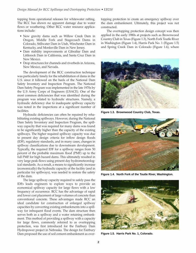
topping protection to create an emergency spillway overthe dam embankment. Ultimately, this project was notconstructed.
The overtopping protection design concept was thenapplied in the early 1980s at projects such as BrownwoodCountry Club in Texas (Figure 1.3), North Fork Toutle Riverin Washington (Figure 1.4), Harris Park No. 1 (Figure 1.5)and Spring Creek Dam in Colorado (Figure 1.6), where
topping from operational releases for whitewater rafting.The RCC has shown no apparent damage due to waterflows or weathering. Other RCC water resource applica-tions include:
• New gravity dams such as Willow Creek Dam inOregon, Middle Fork and Stagecoach Dams inColorado, Stillwater Dam in Utah, Winchester Dam inKentucky, and Monksville Dam in New Jersey.
• Dam stability improvements at Gibraltar Dam andLittlerock Dam in California, and Santa Cruz Dam inNew Mexico.
• Drop structures for channels and riverbeds in Arizona,New Mexico, and Nevada.
The development of the RCC construction techniquewas particularly timely for the rehabilitation of dams in theU.S. since it followed on the heels of the National DamSafety Inventory and Inspection Program. The NationalDam Safety Program was implemented in the late 1970s bythe U.S Army Corps of Engineers (USACE). One of themost common deficiencies that was identified during theprogram was related to hydraulic structures. Namely, ahydraulic deficiency due to inadequate spillway capacitywas noted in the inspections at a significant number offacilities.
Hydraulic deficiencies can often be repaired by reha-bilitating existing spillways. However, during the NationalDam Safety Inventory and Inspection Program, the spill-way capacity that was required for many dams was foundto be significantly higher than the capacity of the existingspillways. The higher required spillway capacity was dueto present day design criteria for inflow design floods(IDF), regulatory standards, and in many cases, changes inspillway classifications due to downstream development.Typically, the required IDF for a spillway ranges from 50percent of the probable maximum flood (PMF) up to thefull PMF for high hazard dams. This ultimately resulted invery large peak flows using present day hydrometeorolog-ical standards. As a result, a means to significantly increase(economically) the hydraulic capacity of the facility (and inparticular for spillways), was needed to restore the safetyof the dam.
The large spillway capacity required to safely pass theIDFs leads engineers to explore ways to provide aneconomical spillway capacity for large flows with a lowfrequency of occurrence. RCC has the advantage of rapidand lower cost placement of large volumes of concrete thanconventional concrete. These advantages made RCC anideal candidate for construction of enlarged spillwaycapacities by converting existing embankments into a spill-way for infrequent flood events. The dam structure thenserves both as a spillway and a water retaining embank-ment. This method of providing a spillway with a capacityfor large flows, commonly referred to as overtoppingprotection, was first introduced for the Fairbury DamHydropower project in Nebraska. The design for FairburyDam proposed the use of soil cement embankment as over-
2
Design Manual for RCC Spillways and Overtopping Protection • EB218
Figure 1.3. Brownwood Country Club, Texas.
Figure 1.4. North Fork of the Toutle River, Washington.
Figure 1.5. Harris Park No. 1, Colorado.

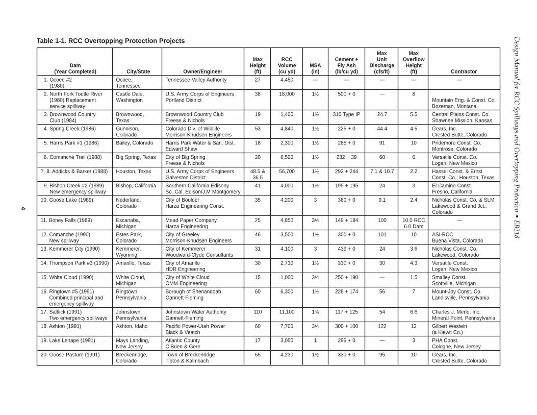
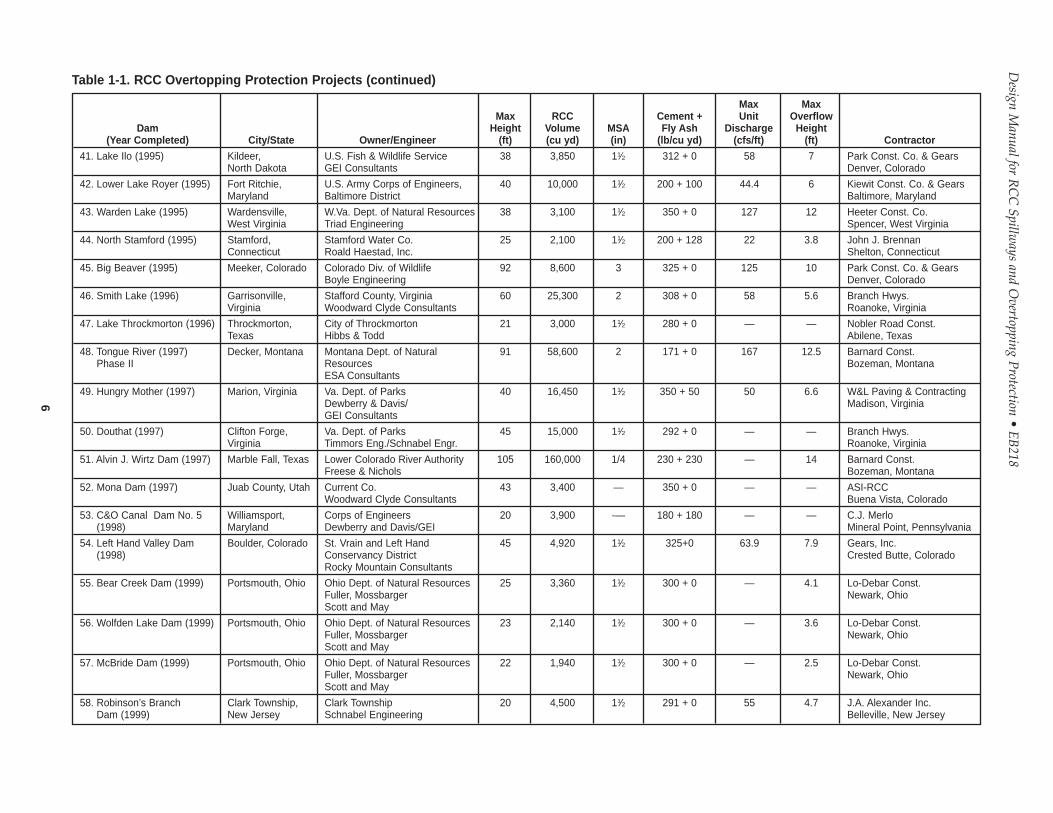
rapid construction and/or budget constraints were drivingforces in identifying alternative designs. The cost effective-ness of RCC overtopping protection was proven in theseearly projects where the relatively high hauling, placement,and compaction production rates yielded lower unit coststhan for conventional concrete spillways. Overtoppingprotection subsequently saw sporadic application in thefollowing years with a total of 11 projects constructed in the1980s, and then continued to grow to almost 50 projects inthe 1990s. The highest structure constructed to date is 110feet. A list of completed overtopping protection projects isshown in Table 1.1.
Overtopping spillway projects generally range inheight from 15 to 65 feet (with five projects over 65 feethigh) with the volume of RCC typically ranging from 1,000to 56,000 yd3. The largest RCC overtopping projectconstructed to date had an RCC volume of 160,000 yd3. Thetypical project averages 35 feet high, with an average RCC
volume of 8,000 yd3, an average spillway discharge of 80cfs per lineal foot width of spillway, and an average over-flow depth of 5 feet.
There are some significant differences betweenconventional concrete and RCC spillways. Conventionalconcrete spillways consist of reinforced, air-entrainedconcrete placed in sections with water-stopped joints,under-drains and anchorage to resist uplift. In contrast,RCC spillways consist of non-air-entrained concrete, with-out reinforcement, water-stopped joints or anchorage. RCCspillways have under-drain systems similar to conven-tional concrete spillways. Also, reinforced concrete spill-ways are rarely constructed over an earth embankment.
RCC spillways/stream control structures have beendesigned for flood frequencies of less than 100 years withlittle or no impoundment storage. For structures thatimpound water such as earth embankments, designingspillways with RCC overtopping protection is generallylimited to emergency spillways with flood frequencies of100 years or higher based on discussions with engineeringpractitioners. When identifying the design flood frequency,the legal liability for the owner of the facility for changes inthe flooding characteristics (both upstream and down-stream) is an important consideration, as well as the tech-nical considerations.
With the rapid growth of overtopping protection proj-ects, the application of RCC has evolved empirically,whereas design methods and analyses have been slower todevelop. This document is intended to primarily be a guidefor the technical application of RCC for overtoppingprotection/spillway enhancement for new and existingembankment dams. However, many of the topics coveredwill be applicable to other hydraulic structures constructedwith RCC.
3
Chapter 1 • RCC Spillways and Overtopping Protection
Figure 1.6. Spring Creek Dam, Colorado.
4
Design M
anual for RC
CSpillw
ays and Overtopping P
rotection• E
B218
Max MaxMax RCC Cement + Unit Overflow
Dam Height Volume MSA Fly Ash Discharge Height(Year Completed) City/State Owner/Engineer (ft) (cu yd) (in) (lb/cu yd) (cfs/ft) (ft) Contractor
1. Ocoee #2 Ocoee, Tennessee Valley Authority 27 4,450 — — — — —(1980) Tennessee
2. North Fork Toutle River Castle Dale, U.S. Army Corps of Engineers 38 18,000 11⁄2 500 + 0 — 8(1980) Replacement Washington Portland District Mountain Eng. & Const. Co.service spillway Bozeman, Montana
3. Brownwood Country Brownwood, Brownwood Country Club 19 1,400 11⁄2 310 Type IP 24.7 5.5 Central Plains Const. Co.Club (1984) Texas Freese & Nichols Shawnee Mission, Kansas
4. Spring Creek (1986) Gunnison, Colorado Div. of Wildlife 53 4,840 11⁄2 225 + 0 44.4 4.5 Gears, Inc.Colorado Morrison-Knudsen Engineers Crested Butte, Colorado
5. Harris Park #1 (1986) Bailey, Colorado Harris Park Water & San. Dist. 18 2,300 11⁄2 285 + 0 91 10 Pridemore Const. Co.Edward Shaw Montrose, Colorado
6. Comanche Trail (1988) Big Spring, Texas City of Big Spring 20 6,500 11⁄2 232 + 39 60 6 Versatile Const. Co.Freese & Nichols Logan, New Mexico
7, 8. Addicks & Barker (1988) Houston, Texas U.S. Army Corps of Engineers 48.5 & 56,700 11⁄2 292 + 244 7.1 & 10.7 2.2 Hassel Const. & ErnstGalveston District 36.5 Const. Co., Houston, Texas
9. Bishop Creek #2 (1989) Bishop, California Southern California Edisony 41 4,000 11⁄2 195 + 195 24 3 El Camino Const.New emergency spillway So. Cal. Edison/J.M Montgomery Fresno, California
10. Goose Lake (1989) Nederland, City of Boulder 35 4,200 3 360 + 0 9.1 2.4 Nicholas Const. Co. & SLMColorado Harza Engineering Const. Lakewood & Grand Jct.,
Colorado
11. Boney Falls (1989) Escanaba, Mead Paper Company 25 4,850 3/4 149 + 184 100 10.0 RCC —Michigan Harza Engineering 6.0 Dam
12. Comanche (1990) Estes Park, City of Greeley 46 3,500 11⁄2 300 + 0 101 10 ASI-RCCNew spillway Colorado Morrison-Knudsen Engineers Buena Vista, Colorado
13. Kemmerer City (1990) Kemmerer, City of Kemmerer 31 4,100 3 439 + 0 24 3.6 Nicholas Const. Co.Wyoming Woodward-Clyde Consultants Lakewood, Colorado
14. Thompson Park #3 (1990) Amarillo, Texas City of Amarillo 30 2,730 11⁄2 330 + 0 30 4.3 Versatile Const.HDR Engineering Logan, New Mexico
15. White Cloud (1990) White Cloud, City of White Cloud 15 1,000 3/4 250 + 190 — 1.5 Smalley Const.Michigan OMM Engineering Scottville, Michigan
16. Ringtown #5 (1991) Ringtown, Borough of Shenandoah 60 6,300 11⁄2 228 + 174 56 7 Mount-Joy Const. Co.Combined principal and Pennsylvania Gannett-Fleming Landisville, Pennsylvaniaemergency spillway
17. Saltlick (1991) Johnstown, Johnstown Water Authority 110 11,100 13⁄4 117 + 125 54 6.6 Charles J. Merlo, Inc.Two emergency spillways Pennsylvania Gannett-Fleming Mineral Point, Pennsylvania
18. Ashton (1991) Ashton, Idaho Pacific Power-Utah Power 60 7,700 3/4 300 + 100 122 12 Gilbert WesteinBlack & Veatch (a Kiewit Co.)
19. Lake Lenape (1991) Mays Landing, Atlantic County 17 3,050 1 295 + 0 — 3 PHA Const.New Jersey O’Brien & Gere Cologne, New Jersey
20. Goose Pasture (1991) Breckenridge, Town of Breckenridge 65 4,230 11⁄2 330 + 0 95 10 Gears, Inc.Colorado Tipton & Kalmbach Crested Butte, Colorado
Table 1-1. RCC Overtopping Protection Projects

5
Chapter 1 • R
CC
Spillways and O
vertopping Protection
Max MaxMax RCC Cement + Unit Overflow
Dam Height Volume MSA Fly Ash Discharge Height(Year Completed) City/State Owner/Engineer (ft) (cu yd) (in) (lb/cu yd) (cfs/ft) (ft) Contractor
21. Holmes Lake Dam (1991) Marshall, Texas T & P Lake, Inc. 31 2,800 21⁄2 300 + 0 — 5 Marshall Paving Co.East Texas Engineering Marshall, Texas
22. White Meadow Lake Rockaway, White Meadow Lake Assn. 20 1,000 1 295 + 0 — 1.4 PHA Const.(1991) New Jersey O’Brien & Gere Cologne, New Jersey
23. Butler Reservoir (1992) Camp Gordon, U.S. Army Corps of Engineers 43 9,150 11⁄2 223 + 162 137 13.2 Curry Contracting Co.Georgia Savannah District Atlanta, Georgia
24. Horsethief (1992) Rapid City, Black Hills National Forest 65 6,250 2 325 + 0 17 4.24 Gears, Inc.South Dakota U.S. Forest Service, Denver Crested Butte, Colorado
25. Meadowlark Lake (1992) Ten Sleep, Bighorn National Forest 28 2,550 2 325 + 0 118 10.25 ASI-RCCWyoming U.S. Forest Service, Denver Buena Vista, Colorado
26. Philipsburg Dam #3 Philipsburg, PA - American Water Co. 20 1,400 1 295 + 0 14 6.9 —(1992) Pennsylvania O’Brien & Gere
27. North Potato Creek Dam Copperhill, Federal Bankruptcy Court 35 4,500 11⁄2 170 + 110 340 20 Dames & Moore(1992) Tennessee Dames & Moore Atlanta, Georgia
28. Lake Diversion (1993) Wichita Falls, City of Wichita Falls 85 43,230 11⁄2 225 + 37 316 20.4 Central Plains Const.New emergency spillway Texas Biggs & Mathews Shawnee Mission, Kansas
29. Lima (1993) Dell, Montana Beaverhead Co. Red Rock River 54 14,800 2 417 + 0 61 9.3 Pete’s ExcavatingW&S District, HKM Assoc. Torrington, Wyoming
30. Rosebud (1993) Rosebud, Rosebud Sioux Tribe 33 4,700 1 131 + 151 55 7 Pete’s ExcavatingSouth Dakota Harza Engineering Torrington, Wyoming
31. Umbarger (1993) Canyon, Texas U.S. Fish & Wildlife Service 40 28,500 11⁄2 330 + 0 216 17.5 ASI-RCCGEI Consultants Buena Vista, Colorado
32. Ponca (1993) Herrick, Rosebud Sioux Tribe 35 7,700 1 200 + 170 167 16 Gears, Inc.South Dakota Harza Engineering Crested Butte, Colorado
33. Lighthouse Hill (1993) Altmar, Niagara Mohawk Power 18 4,700 11⁄2 295 + 0 50 6.5 Tuscarara Const. Co.New York O’Brien & Gere Pulaski, New York
34. He Dog (1994) Paramalee, Rosebud Sioux Tribe 45 9,500 1 200 + 170 190 17 Pete’s ExcavatingCombined principal and South Dakota Harza Engineering Torrington, Wyomingemergency spillway
35. Long Run (1994) Lehighton, Borough of Lehighton 28.5 3,100 1 250 + 150 15.6 2.5 KC Const. & VFLPennsylvania Gannett Fleming Huntington Valley,
Pennsylvania
36. Lake Dorothy (1994) Barberton, Ohio PPG Industries 35 6,000 11⁄2 197 + 142 — 4 Kokosing Const. Co.ICF Kaiser Engineers Loudenville, Ohio
37. South Dam #1 (1994) St. Clairsville, Ohio City of St. Clairsville 40 2,200 1 250 + 0 16.0 3 Beaver ExcavatingBurgess & Niple Canton, Ohio
38. Anawalt (1994) Anawalt, W.Va. Dept. of Natural Resources 34 3,000 2 361 + 0 61 7.83 Heeter Const. Co. & GearsWest Virginia Triad Engineering Spencer, West Virginia
39. North Poudre #6 (1994) Wellington, North Poudre Irrigation Co. 40 2,400 1 350 + 0 30 5 National Const. & GearsColorado Smith Geotechnical Boulder, Colorado
40. South Prong (1994) Waxahachie, Texas Ellis Co., WC&I Dist #1 62 52,000 11⁄2 210 + 105 & 48 6.25 Central PlainsFreese & Nichols 270 + 0 Shawnee Mission, Kansas
Table 1-1. RCC Overtopping Protection Projects (continued)
6
Design M
anual for RC
CSpillw
ays and Overtopping P
rotection• E
B218
Max MaxMax RCC Cement + Unit Overflow
Dam Height Volume MSA Fly Ash Discharge Height(Year Completed) City/State Owner/Engineer (ft) (cu yd) (in) (lb/cu yd) (cfs/ft) (ft) Contractor
41. Lake Ilo (1995) Kildeer, U.S. Fish & Wildlife Service 38 3,850 11⁄2 312 + 0 58 7 Park Const. Co. & GearsNorth Dakota GEI Consultants Denver, Colorado
42. Lower Lake Royer (1995) Fort Ritchie, U.S. Army Corps of Engineers, 40 10,000 11⁄2 200 + 100 44.4 6 Kiewit Const. Co. & GearsMaryland Baltimore District Baltimore, Maryland
43. Warden Lake (1995) Wardensville, W.Va. Dept. of Natural Resources 38 3,100 11⁄2 350 + 0 127 12 Heeter Const. Co.West Virginia Triad Engineering Spencer, West Virginia
44. North Stamford (1995) Stamford, Stamford Water Co. 25 2,100 11⁄2 200 + 128 22 3.8 John J. BrennanConnecticut Roald Haestad, Inc. Shelton, Connecticut
45. Big Beaver (1995) Meeker, Colorado Colorado Div. of Wildlife 92 8,600 3 325 + 0 125 10 Park Const. Co. & GearsBoyle Engineering Denver, Colorado
46. Smith Lake (1996) Garrisonville, Stafford County, Virginia 60 25,300 2 308 + 0 58 5.6 Branch Hwys.Virginia Woodward Clyde Consultants Roanoke, Virginia
47. Lake Throckmorton (1996) Throckmorton, City of Throckmorton 21 3,000 11⁄2 280 + 0 — — Nobler Road Const.Texas Hibbs & Todd Abilene, Texas
48. Tongue River (1997) Decker, Montana Montana Dept. of Natural 91 58,600 2 171 + 0 167 12.5 Barnard Const.Phase II Resources Bozeman, Montana
ESA Consultants
49. Hungry Mother (1997) Marion, Virginia Va. Dept. of Parks 40 16,450 11⁄2 350 + 50 50 6.6 W&L Paving & ContractingDewberry & Davis/ Madison, VirginiaGEI Consultants
50. Douthat (1997) Clifton Forge, Va. Dept. of Parks 45 15,000 11⁄2 292 + 0 — — Branch Hwys.Virginia Timmors Eng./Schnabel Engr. Roanoke, Virginia
51. Alvin J. Wirtz Dam (1997) Marble Fall, Texas Lower Colorado River Authority 105 160,000 1/4 230 + 230 — 14 Barnard Const.Freese & Nichols Bozeman, Montana
52. Mona Dam (1997) Juab County, Utah Current Co. 43 3,400 — 350 + 0 — — ASI-RCCWoodward Clyde Consultants Buena Vista, Colorado
53. C&O Canal Dam No. 5 Williamsport, Corps of Engineers 20 3,900 -— 180 + 180 — — C.J. Merlo(1998) Maryland Dewberry and Davis/GEI Mineral Point, Pennsylvania
54. Left Hand Valley Dam Boulder, Colorado St. Vrain and Left Hand 45 4,920 11⁄2 325+0 63.9 7.9 Gears, Inc.(1998) Conservancy District Crested Butte, Colorado
Rocky Mountain Consultants
55. Bear Creek Dam (1999) Portsmouth, Ohio Ohio Dept. of Natural Resources 25 3,360 11⁄2 300 + 0 — 4.1 Lo-Debar Const.Fuller, Mossbarger Newark, OhioScott and May
56. Wolfden Lake Dam (1999) Portsmouth, Ohio Ohio Dept. of Natural Resources 23 2,140 11⁄2 300 + 0 — 3.6 Lo-Debar Const.Fuller, Mossbarger Newark, OhioScott and May
57. McBride Dam (1999) Portsmouth, Ohio Ohio Dept. of Natural Resources 22 1,940 11⁄2 300 + 0 — 2.5 Lo-Debar Const.Fuller, Mossbarger Newark, OhioScott and May
58. Robinson’s Branch Clark Township, Clark Township 20 4,500 11⁄2 291 + 0 55 4.7 J.A. Alexander Inc.Dam (1999) New Jersey Schnabel Engineering Belleville, New Jersey
Table 1-1. RCC Overtopping Protection Projects (continued)

7
Chapter 1 • R
CC
Spillways and O
vertopping Protection
Max MaxMax RCC Cement + Unit Overflow
Dam Height Volume MSA Fly Ash Discharge Height(Year Completed) City/State Owner/Engineer (ft) (cu yd) (in) (lb/cu yd) (cfs/ft) (ft) Contractor
59. Lake Tholocco Dam Fort Rucker, U.S. Army Corps of Engineers 36 26,000 11⁄2 275 + 50 — 6.5 Thalle Construction(2000) Alabama Mebane, North Carolina
60. Saddle Lake Dam (2000) Hooiser National Hoosier National Forest 49 9,100 — 320+0 — 8.1 T-C Inc.Forest, Indiana NRCS, Ohio Indianapolis, Indiana
61. Gunnison Dam (2000) Gunnison, Utah Gunnison Irrigation District 35 3,700 11⁄2 350 + 0 81 9 Nordic Ind.Jones & DeMille Engineering Salt Lake City, Utah
62. Coal Ridge Waste Dam Longmont, Platte Valley Irrigation Co. 28 2,300 11⁄2 325+0 — 5.0 DeFalco-Lee(2000) Colorado Rocky Mountain Consultants Longmont, Colorado
63. Teter Creek (2000) West Virginia Civil Tech Engineering 28 5,700 — 361+0 — 12.0 West Virginia PavingBarbour County Grafton, West Virginia
64. Many Farms (2000) Many Farms, Bureau of Reclamation 45 6,200 11⁄2 280+70 — 7.1 Barnard ConstructionArizona Bozeman, Montana
65. Fawell Dam (2000) Naperville, Illinois Dupage County 23 9,200 11⁄2 375 + 0 — 3.5 James Cape & SonsURS Corp. Racine, Wisconsin
66. Leyden Dam (2001) Arvada, Colorado City of Arvada 8,900 11⁄2 425 92 8.4 ASI RCCURS Corp. Buena Vista, Colorado
67. McKinney (2001) Hoffman, N.C. Wildlife Resource Comm. 17 1,570 11⁄2 450+0 47 5 Atlas ResourceNorth Carolina URS Corp/Schnabel Engr. Management
Fayetteville, North Carolina
68. Jackson Lake Dam (2001) Jackson, Ohio Ohio Dept of Natural Resources 23 3,600 — 309+0 30 4.6 LoDeBar, Inc.BBC&M Newark, Ohio
69. Vesuvius (2001) Ironton, Ohio U.S. Forest Service 45 10,000 — 360+0 35 5.7 TC, Inc.Bureau of Reclamation Indianapolis, Indiana
70. Potato Ck No. 6 (2002) Thomaston, GA Upson Co. and Towaliga River 28 4,730 11/2 — 34.5 4.5 DPSSoil & Water Consrv. District Marrietta, GeorgiaGolder Associates
Table 1-1. RCC Overtopping Protection Projects (continued)

Design Manual for RCC Spillways and Overtopping Protection • EB218
8
9
CHAPTER 2
Operational Requirements and Spillway Location
2.1 GENERAL
Embankment overtopping protection has been found to bea practical, and cost-effective method for providing addi-tional spillway capacity to convey infrequent floods atexisting dams with inadequate spillway capacity. Manydam designers and dam safety officials have accepted over-topping spillways for embankment dams as an effectivedesign method of adding emergency spillway capacity.When planning to use embankment overtopping protec-tion as an emergency spillway, the designer shouldconsider the limitations and risks of conveying spillwayflow over an earth embankment. Important engineeringdesign considerations that should be evaluated include:
• The use of an overtopping protection configurationintroduces significant quantities of concentrated flow-ing water over erodible materials such as an earthenembankment or foundation material at the abutmentcontacts; which is not a typical engineering design.
• Embankment overtopping protection has the inherentrisk that uncontrolled leakage from the spillway couldcause embankment erosion. Therefore, preferenceshould be given to alternatives that will locate thespillway off of the dam embankment, and on a rockfoundation, where possible.
• Overtopping protection should not be considered as alow-cost substitute for a service spillway especiallywhere frequent use, high unit discharge, or high headis a design requirement, or the structure impounds asubstantial volume of water.
• Overtopping protection typically involves a significantchange to the visual appearance of the structure. RCCovertopping protection changes a grass coveredembankment to a concrete covered surface. In addi-tion, RCC usually has a rough, unfinished appearancewhen compared with conventional concrete. Someconsider the rough surface of RCC to be visually moreappealing than conventional concrete. The aestheticsof RCC definitely depends on the eye of the beholder,the project setting, and the materials used in construc-
tion. Education of owners and the public regarding theaesthetics of RCC is important.
• Numerous overtopping protection projects have beenconstructed, but few have seen significant use andhave not been tested for full design flood conditions.
• There is the risk that debris carried in the flood flowswill impact or erode the overtopping protection.
2.2 OPERATION FREQUENCY ANDSPILLWAY LOCATION
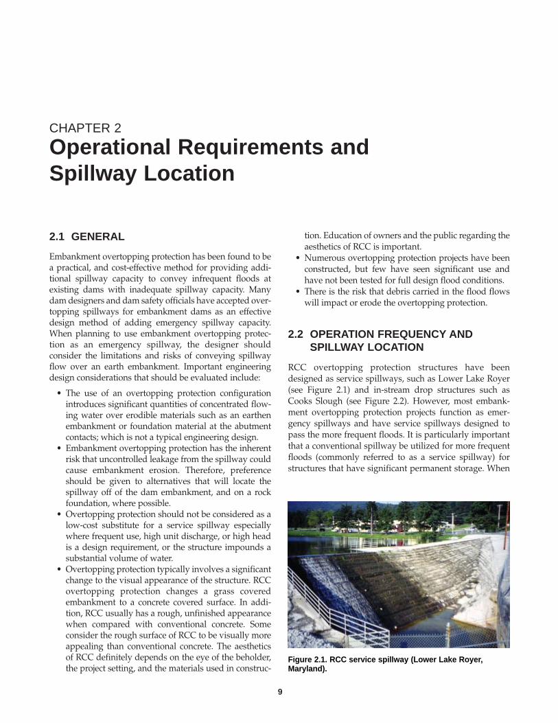
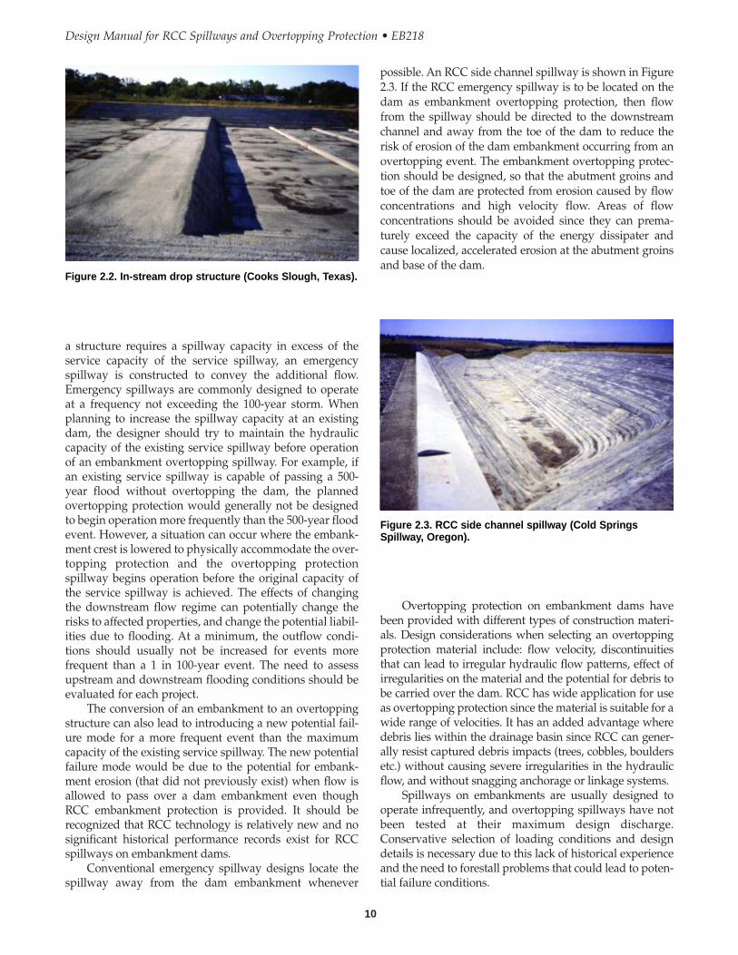
RCC overtopping protection structures have beendesigned as service spillways, such as Lower Lake Royer(see Figure 2.1) and in-stream drop structures such asCooks Slough (see Figure 2.2). However, most embank-ment overtopping protection projects function as emer-gency spillways and have service spillways designed topass the more frequent floods. It is particularly importantthat a conventional spillway be utilized for more frequentfloods (commonly referred to as a service spillway) forstructures that have significant permanent storage. When
Figure 2.1. RCC service spillway (Lower Lake Royer,Maryland).
Overtopping protection on embankment dams havebeen provided with different types of construction materi-als. Design considerations when selecting an overtoppingprotection material include: flow velocity, discontinuitiesthat can lead to irregular hydraulic flow patterns, effect ofirregularities on the material and the potential for debris tobe carried over the dam. RCC has wide application for useas overtopping protection since the material is suitable for awide range of velocities. It has an added advantage wheredebris lies within the drainage basin since RCC can gener-ally resist captured debris impacts (trees, cobbles, bouldersetc.) without causing severe irregularities in the hydraulicflow, and without snagging anchorage or linkage systems.
Spillways on embankments are usually designed tooperate infrequently, and overtopping spillways have notbeen tested at their maximum design discharge.Conservative selection of loading conditions and designdetails is necessary due to this lack of historical experienceand the need to forestall problems that could lead to poten-tial failure conditions.
a structure requires a spillway capacity in excess of theservice capacity of the service spillway, an emergencyspillway is constructed to convey the additional flow.Emergency spillways are commonly designed to operateat a frequency not exceeding the 100-year storm. Whenplanning to increase the spillway capacity at an existingdam, the designer should try to maintain the hydrauliccapacity of the existing service spillway before operationof an embankment overtopping spillway. For example, ifan existing service spillway is capable of passing a 500-year flood without overtopping the dam, the plannedovertopping protection would generally not be designedto begin operation more frequently than the 500-year floodevent. However, a situation can occur where the embank-ment crest is lowered to physically accommodate the over-topping protection and the overtopping protectionspillway begins operation before the original capacity ofthe service spillway is achieved. The effects of changingthe downstream flow regime can potentially change therisks to affected properties, and change the potential liabil-ities due to flooding. At a minimum, the outflow condi-tions should usually not be increased for events morefrequent than a 1 in 100-year event. The need to assessupstream and downstream flooding conditions should beevaluated for each project.
The conversion of an embankment to an overtoppingstructure can also lead to introducing a new potential fail-ure mode for a more frequent event than the maximumcapacity of the existing service spillway. The new potentialfailure mode would be due to the potential for embank-ment erosion (that did not previously exist) when flow isallowed to pass over a dam embankment even thoughRCC embankment protection is provided. It should berecognized that RCC technology is relatively new and nosignificant historical performance records exist for RCCspillways on embankment dams.
Conventional emergency spillway designs locate thespillway away from the dam embankment whenever
10
Design Manual for RCC Spillways and Overtopping Protection • EB218
possible. An RCC side channel spillway is shown in Figure2.3. If the RCC emergency spillway is to be located on thedam as embankment overtopping protection, then flowfrom the spillway should be directed to the downstreamchannel and away from the toe of the dam to reduce therisk of erosion of the dam embankment occurring from anovertopping event. The embankment overtopping protec-tion should be designed, so that the abutment groins andtoe of the dam are protected from erosion caused by flowconcentrations and high velocity flow. Areas of flowconcentrations should be avoided since they can prema-turely exceed the capacity of the energy dissipater andcause localized, accelerated erosion at the abutment groinsand base of the dam.
Figure 2.2. In-stream drop structure (Cooks Slough, Texas).
Figure 2.3. RCC side channel spillway (Cold SpringsSpillway, Oregon).
embankment and can also cause high seepage gradients tooccur at the toe of the dam. Excavation at the toe of theembankment to construct the various features of the over-topping protection, in particular for the downstreamapron or over steepening of the downstream slope, willchange the stability of the overall embankment. If erosionat the toe of the dam is expected to occur during overtop-ping, then the eroded conditions should be evaluated inboth the embankment stability and embankment seepageanalyses. These critical stability and seepage conditionsmust be considered in the overtopping protection andembankment design.
11
Chapter 2 • Operational Requirements and Spillway Location
2.3 DAM STABILITY AND DOWNSTREAMEROSION
Construction of RCC overtopping protection will alsoimpact the stability of the embankment. RCC on the down-stream slope of the embankment can block existing seep-age paths and increase the phreatic level and decreaseembankment stability. Changes to the embankment sectioncan decrease the factor of safety for slope stability, in partic-ular for excavation slopes during construction.
Erosion downstream of embankment overtoppingprotection can have a critical impact on the stability of the

Design Manual for RCC Spillways and Overtopping Protection • EB218
12

CHAPTER 3
Investigation
3.1 GENERAL
Before designing modifications to an existing dam, theembankment should be investigated to understand thecurrent condition of the embankment, foundation, anddownstream area, and to develop appropriate geotechnicalparameters for design of the modifications. Geotechnicaldesign parameters will generally be needed for analyzingembankment stability and seepage, evaluating the impactof the proposed modifications, estimating the bearingcapacity of the foundation, providing analysis of filter com-patibility, predicting heave or settlement, and designing re-taining wall and other structures. There may be specialfeatures or conditions associated with some projects thatwill also need to be included when planning the investiga-tion. An experienced geotechnical engineer should beutilized for developing the investigation program.
This section describes guidelines for investigation ofmodifications to existing dams. For RCC overtoppingdesign on a new dam, the objectives of investigation aregenerally the same as for existing dams. However, evaluat-ing the properties of the embankment and developinginformation to predict the behavior and condition follow-ing construction need to be included.
3.2 DESK STUDY AND SITERECONNAISSANCE
The first phase of investigation involves a desk study priorto the site reconnaissance and investigation. Availableinformation on existing dams should be reviewed todevelop an understanding of how the dam wasconstructed and how it has performed. The type of infor-mation can include design and construction drawings,construction records and photographs, records of inspec-tions, and reviews by owners or jurisdictional agencies. Insome cases, there may be substantial structure performancedata from instrumentation programs. Instrumentation willusually include monitoring of the phreatic surface within
the dam, seepage measurements, and surface movement.Additional information can often be obtained from theowner’s staff familiar with the operation and maintenanceof the existing facility.
Whether or not instrumentation is in place or has beenmonitored, visual observations can provide considerableinformation on the past performance of the dam. Highphreatic levels, seepage, settlement, and shear displace-ment generally leave surface expressions that can beobserved during a site reconnaissance. Guidelines havebeen prepared for conducting inspection of dam embank-ments, for example, USBR (1983), FEMA (1987), and somestate dam safety agencies. These guidelines include stan-dard forms for evaluating the dam embankment and thefoundation downstream of the dam.
3.3 SUBSURFACE INVESTIGATION
Subsurface investigations are used to delineate subsurfacestrata and water levels in the embankment and foundation,and to collect samples for laboratory testing. Of particularinterest are the subsurface material and water levels(phreatic surface) in the downstream slope and in the foun-dation at the downstream toe. The scope of investigationusually includes drilling of test holes and/or excavation oftest pits, with associated logging and sampling. Thesubsurface investigation scope should be planned andimplemented under the direction of a qualified geotechni-cal engineer experienced in dam design.
Geophysical methods such as seismic refraction,ground penetrating radar, and electrical resistivity, mayapply to RCC overtopping protection investigation. Addi-tional subsurface investigation methods include ConePenetration Testing (where the resistance and response ofpushing a cone into the ground is monitored, but nosample is retrieved), and bucket auger drilling (where alarge diameter hole is drilled and a person is lowered intothe hole to collect samples and record observations). Thesemethods and other less common investigation methods
13
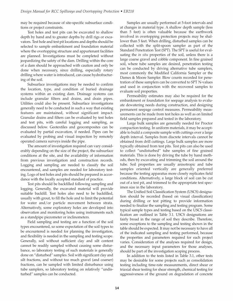
Samples are usually performed at 5-foot intervals andat changes in material type. A shallow depth sample (lessthan 5 feet) is often valuable because the earthworkinvolved in overtopping protection projects may be shal-lower than 5 feet. When drilling, disturbed samples can becollected with the split-spoon sampler as part of theStandard Penetration Test (SPT). The SPT is useful for eval-uating the in situ properties of the soil, unless there is alarge coarse gravel and cobble component. In fine grainedsoil, where tube samples are desired, penetration testingcan be conducted by driving alternative tube samplers,most commonly the Modified California Sampler or theDames & Moore Sampler. Blow counts recorded for pene-tration of these samplers can be converted to SPT N-valuesand used in conjunction with the recovered samples toevaluate soil properties.
Permeability estimates may also be required for theembankment or foundation for seepage analysis to evalu-ate dewatering needs during construction, and designingpermanent seepage control measures. Permeability meas-urements can be made from test holes as well as on limitedfield samples prepared and tested in the laboratory.
Large bulk samples are generally needed for Proctorcompaction testing. In uniform materials, it may be accept-able to build a composite sample with cuttings over a largedepth interval. Samples from discrete intervals cannot beobtained from drill cuttings. Large bulk samples are moretypically obtained from test pits. Test pits can also be usedto collect “undisturbed” tube samples of fine grainedmaterials. This is done by driving the tube by hand meth-ods, then by excavating and trimming the soil around thetube. Soil properties are usually anisotropic and tubesamples oriented vertically are generally preferredbecause the testing apparatus more closely replicates fieldconditions. Alternatively, a large block of soil can be cutout of a test pit, and trimmed to the appropriate test spec-imen size in the laboratory.
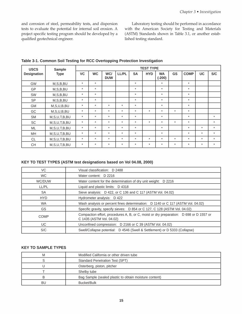
The Unified Soil Classification System (USCS) designa-tion should be recorded (based on visual classification)during drilling or test pitting to provide informationneeded to finalize the sampling and testing program. Sometypical sample types and testing based on the USCS classi-fication are outlined in Table 3.1. USCS designations arefairly broad in the range of soil they describe. Therefore,some exceptions to the sampling and testing shown in thetable should be expected. It may not be necessary to have allof the indicated sampling and testing performed, becausethe properties and parameters required for each projectvaries. Consideration of the analyses required for design,and the necessary input parameters for those analyses,should be part of the investigation scoping process.
In addition to the tests listed in Table 3.1, other testsmay be desirable for some projects such as consolidationtesting including time-rate measurements, direct shear ortriaxial shear testing for shear strength, chemical testing foraggressiveness of the ground on degradation of concrete
may be required because of site-specific subsurface condi-tions or project constraints.
Test holes and test pits can be excavated to shallowdepth by hand and to greater depths by drill rigs or exca-vators. Test hole and test pit locations and depths should beselected to sample embankment and foundation materialwhere the overtopping structure and appurtenant facilitiesare planned. Investigations must be completed withoutjeopardizing the safety of the dam. Drilling within the coreof a dam should be approached with caution and only bedone when necessary, since drilling, especially rotarydrilling where water is introduced, can cause hydrofractur-ing of the soil.
Subsurface investigations may be needed to confirmthe location, type, and condition of buried drainagesystems within an existing dam. Drainage systems caninclude granular filters and drains, and drain pipes.Utilities could also be present. Subsurface investigationsgenerally need to be conducted in such a way that existingfeatures are maintained, without significant impact.Granular drains and filters can be evaluated by test holesand test pits, with careful logging and sampling, asdiscussed below. Geotextiles and geocomposites can beevaluated by partial excavation, if needed. Pipes can beevaluated by probing and visual inspection by remotelyoperated camera surveys inside the pipe.
The amount of investigation required can vary consid-erably depending on the size of the project, the subsurfaceconditions at the site, and the availability of informationfrom previous investigation and construction records.Logging and sampling are needed to classify the soilencountered, and samples are needed for laboratory test-ing. Logs of test holes and pits should be prepared in accor-dance with the locally accepted standard of practice.
Test pits should be backfilled following sampling andlogging. Generally, the excavated material will providesuitable backfill. Test holes also need to be backfilled,usually with grout, to fill the hole and to limit the potentialfor water and/or particle movement between strata.Alternatively, some exploratory holes are developed intoobservation and monitoring holes using instruments suchas a standpipe piezometer or inclinometers.
Field sampling and testing are a function of the soiltypes encountered, so some expectation of the soil types tobe encountered is needed for planning the investigation,and flexibility is needed in the sampling and testing scope.Generally, soil without sufficient clay and silt contentcannot be readily sampled without causing some distur-bance, so laboratory testing of such materials is generallydone on “disturbed” samples. Soil with significant clay andsilt fractions, and without too much gravel (and coarser)fractions, can be sampled with limited disturbance usingtube samplers, so laboratory testing on relatively “undis-turbed” samples can be conducted.
14
Design Manual for RCC Spillways and Overtopping Protection • EB218
and corrosion of steel, permeability tests, and dispersiontests to evaluate the potential for internal soil erosion. Aproject specific testing program should be developed by aqualified geotechnical engineer.
Laboratory testing should be performed in accordancewith the American Society for Testing and Materials(ASTM) Standards shown in Table 3.1, or another estab-lished testing standard.
15
Chapter 3 • Investigation
USCS Sample TEST TYPE
Designation Type VC WC WC/ LL/PL SA HYD WA GS COMP UC S/CDUW (-200)
GW M,S,B,BU * * * * *
GP M,S,B,BU * * * * *
SW M,S,B,BU * * * * *
SP M,S,B,BU * * * * *
GM M,S,U,B,BU * * * * * * *
GC M,S,U,B,BU * * * * * * * * *
SM M,S,U,T,B,BU * * * * * * * *
SC M,S,U,T,B,BU * * * * * * * * * *
ML M,S,U,T,B,BU * * * * * * * * *
MH M,S,U,T,B,BU * * * * * * * * *
CL M,S,U,T,B,BU * * * * * * * * * * *
CH M,S,U,T,B,BU * * * * * * * * * * *
Table 3-1. Common Soil Testing for RCC Overtopping Protection Investigation
KEY TO TEST TYPES (ASTM test designations based on Vol 04.08, 2000)
VC Visual classification: D 2488
WC Water content: D 2216
WC/DUW Water content for the determination of dry unit weight: D 2216
LL/PL Liquid and plastic limits: D 4318
SA Sieve analysis: D 422, or C 136 and C 117 (ASTM Vol. 04.02)
HYD Hydrometer analysis: D 422
WA Wash analysis or percent fines determination: D 1140 or C 117 (ASTM Vol. 04.02)
GS Specific gravity, specify sieves: D 854 or C 127, C 128 (ASTM Vol. 04.02)
COMP Compaction effort, procedures A, B, or C, moist or dry preparation: D 698 or D 1557 orC 1435 (ASTM Vol. 04.02)
UC Unconfined compression: D 2166 or C 39 (ASTM Vol. 04.02)
S/C Swell/Collapse potential: D 4546 (Swell & Settlement) or D 5333 (Collapse)
KEY TO SAMPLE TYPES
M Modified California or other driven tube
S Standard Penetration Test (SPT)
U Osterberg, piston, pitcher
T Shelby tube
B Bag Sample (sealed plastic to obtain moisture content)
BU Bucket/Bulk
16
Design Manual for RCC Spillways and Overtopping Protection • EB218
determine the range of suitable material that is alreadyavailable.
After canvassing the existing material sources,samples should be obtained to confirm the material prop-erties of the most readily available and cost-effectivesources that are identified as suitable for use in the RCCmix. Testing should include at a minimum the followingtests: mechanical analyses, Atterberg limits, specific grav-ity, and absorption. Additional tests that may be required,if there is not a documented history of the aggregate prop-erties at the source(s), should also include: soundness,mineralogy, Los Angeles Abrasion, freeze-thaw durability,and silica-alkali reactivity. The variability of the aggregateproperties with existing sources, in particular the fines(minus 200 sieve size) content, specific gravity, and absorp-tion, should also be evaluated before a specific source isidentified for a project, as variations in these propertieshave a significant effect on the mixture proportioning andworkability of the RCC.
Based on the initial data gathering on the quality,quantity, availability, and cost of existing sources, a judge-ment can be made on whether additional sources of aggre-gate should be investigated. Investigations of aggregatesources should be conducted to confirm a minimum oftwice the quantity of material needed for the project.Investigations of new sources can be conducted by acombination of test pits, drill holes, and core drilling.
Two other investigation methods should also beconsidered for large volume projects: large volumesampling and test blasting. Large volume sampling is (1)based on obtaining the maximum size of the material(ASTM D 75), field measurement, and splitting of samplesfrom test pits, or (2) sampling in a dump truck (8 yd3 orlarger size sample) and processing at an aggregate plant ora laboratory to more fully evaluate borrow sources withlarge size aggregates. A test blast investigation wouldinclude excavation and processing of the material to assessthe aggregate properties, and to develop material for labo-ratory mix designs. Test blasts at potential quarry sites aretypically performed primarily for larger projects (in excessof 50,000 yd3).
3.4 RCC AGGREGATE INVESTIGATIONS
Potential aggregate sources for RCC include near or on-sitenatural deposits, existing pits or quarries, and new or oldinactive quarries. Borrow investigations are conducted toidentify and locate potential aggregate sources to be usedfor design, specifications, and cost estimates. The approachto the aggregate borrow investigation will be influenced bythe project size, location, and site conditions.
The volume of material required generally has themost influence on identifying borrow sources for a project.Projects in urban settings can benefit from already estab-lished suppliers of sand and gravel that provide a readyand economic source of material, particularly when morethan one supplier is available. The volume of materialrequired for most projects will generally not be limited bythe availability and supply from existing suppliers,however, large volume projects can often require a peakdemand that existing suppliers cannot meet. This can bepartially offset by the Owner/Engineer working with localsuppliers on the project need and schedule in advance ofthe project. In remote sites, the cost of aggregate haulingcan make established, fixed location aggregate sources rela-tively expensive, and development of near or on-site pits orquarries should be considered.
At remote sites, the volume of RCC required can havea significant effect on the potential borrow sources thatwould be used for a project. On projects with smallvolumes required, such as 2,000 yd3 or less, it will seldombe economical to open a new pit or quarry. Development ofa new quarry/pit becomes more economical as the volumeincreases from 2,000 yd3 to 20,000 yd3 or more.
Planning the investigation for aggregate borrowsources should start with an assessment of the variousconditions described above. An investigation would typi-cally include contacting local contractors and suppliers,county road departments, and state departments of trans-portation to ascertain available information on existing orpreviously used quarries and pits. There is often sufficientavailable information that the initial investigation can beperformed with only limited sampling and testing, to
CHAPTER 4
Slope Stability and Foundation Analysis
4.1 GENERAL
An important aspect of constructing a spillway is the stabil-ity of the foundation. Slope stability analysis is required toevaluate whether an existing structure will have an accept-able factor of safety against slope failure during construc-tion and after construction is complete. Foundationanalyses are also required to evaluate other potentialmodes of failure of the proposed modifications, such asbearing capacity, settlement or heave, overturning failureof retaining walls, and sliding.
Certain projects may have special aspects that requireanalyses of specific conditions not described here. In someinstances, more sophisticated models, such as finiteelement or finite difference models of deformation may bewarranted. However, the standard analyses described hereis useful as a basis for determining whether more sophisti-cated analyses are needed, and for evaluating the results ofother analyses or methods.
4.2 SLOPE STABILITY
Most dam modifications for RCC overtopping protectionprojects do not reduce the factor of safety against slopefailure since they do not create significant changes to load-ing or water levels within the dam. In some cases, the needfor computer-based slope stability analysis may be waivedbased on inspection by geotechnical engineers experi-enced in embankment stability, and analysis based onclosed form/chart solutions. However, because of theconsequences of slope failure, slope stability analysis isgenerally appropriate and should be performed. Thefollowing paragraphs describe typical procedures andmethods of analysis.
Slope stability analyses consist of five primary steps:
1. Characterizing the geometry of the slope and materialboundaries.
2. Evaluating the material properties for each type ofmaterial in the embankment and foundation.
3. Evaluating internal and external water pressure andloading/seepage conditions.
4. Inputting geometry, material properties, and waterpressure in a model for analysis of slope stability.
5. Solving for the minimum theoretical factor of safety.
Input parameters for slope stability analysis includematerial boundaries, water pressures or phreatic levels,material unit weights, and material strengths. Water pres-sure and strength parameters are most important becausethey can have a significant effect on the calculated factorof safety.
Unlike many construction materials, the strength ofsoil is highly dependent on loading conditions. Strengthparameters c and φ, which describe the cohesion interceptand friction angle of a material, respectively, are generallyappropriate for analysis. Whether the parameters shouldbe based on effective or total stresses depends on loadingconditions being analyzed (e.g., end of construction, steadyseepage, etc.). Strength parameters should be developed byan experienced geotechnical engineer.
Strength parameters to be used for end-of-construc-tion analysis should be the lowest of: (1) current condi-tions prior to the proposed modifications, or (2) futureconditions following the proposed modifications.Strength parameters to be used for steady seepage analy-sis should reflect the projected change in conditions(density, water content, seepage, etc.). The analysis shouldconsider that the RCC may act as a barrier to evaporation,evapotranspiration, and seepage, and the phreatic surfacemay increase as discussed in Section 5.0 Seepage Analysis.If the RCC strength is included in stability analysis, itshould be assumed that the RCC is cracked (transverse)and the strength on shear surfaces passing through theRCC is frictional.
Standard loading conditions for embankment damsinclude end-of-construction, steady-state seepage fornormal pool conditions, steady-state seepage at flood pool,steady-state seepage earthquake loading conditions, andduring rapid drawdown. These loading conditions areshown in Table 4.1 with published recommended criteria
17
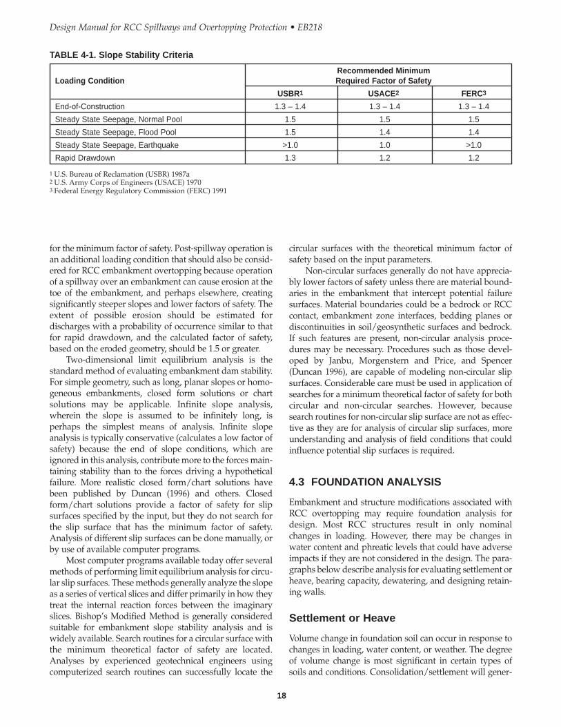
18
Design Manual for RCC Spillways and Overtopping Protection • EB218
circular surfaces with the theoretical minimum factor ofsafety based on the input parameters.
Non-circular surfaces generally do not have apprecia-bly lower factors of safety unless there are material bound-aries in the embankment that intercept potential failuresurfaces. Material boundaries could be a bedrock or RCCcontact, embankment zone interfaces, bedding planes ordiscontinuities in soil/geosynthetic surfaces and bedrock.If such features are present, non-circular analysis proce-dures may be necessary. Procedures such as those devel-oped by Janbu, Morgenstern and Price, and Spencer(Duncan 1996), are capable of modeling non-circular slipsurfaces. Considerable care must be used in application ofsearches for a minimum theoretical factor of safety for bothcircular and non-circular searches. However, becausesearch routines for non-circular slip surface are not as effec-tive as they are for analysis of circular slip surfaces, moreunderstanding and analysis of field conditions that couldinfluence potential slip surfaces is required.
4.3 FOUNDATION ANALYSIS
Embankment and structure modifications associated withRCC overtopping may require foundation analysis fordesign. Most RCC structures result in only nominalchanges in loading. However, there may be changes inwater content and phreatic levels that could have adverseimpacts if they are not considered in the design. The para-graphs below describe analysis for evaluating settlement orheave, bearing capacity, dewatering, and designing retain-ing walls.
Settlement or Heave
Volume change in foundation soil can occur in response tochanges in loading, water content, or weather. The degreeof volume change is most significant in certain types ofsoils and conditions. Consolidation/settlement will gener-
for the minimum factor of safety. Post-spillway operation isan additional loading condition that should also be consid-ered for RCC embankment overtopping because operationof a spillway over an embankment can cause erosion at thetoe of the embankment, and perhaps elsewhere, creatingsignificantly steeper slopes and lower factors of safety. Theextent of possible erosion should be estimated fordischarges with a probability of occurrence similar to thatfor rapid drawdown, and the calculated factor of safety,based on the eroded geometry, should be 1.5 or greater.
Two-dimensional limit equilibrium analysis is thestandard method of evaluating embankment dam stability.For simple geometry, such as long, planar slopes or homo-geneous embankments, closed form solutions or chartsolutions may be applicable. Infinite slope analysis,wherein the slope is assumed to be infinitely long, isperhaps the simplest means of analysis. Infinite slopeanalysis is typically conservative (calculates a low factor ofsafety) because the end of slope conditions, which areignored in this analysis, contribute more to the forces main-taining stability than to the forces driving a hypotheticalfailure. More realistic closed form/chart solutions havebeen published by Duncan (1996) and others. Closedform/chart solutions provide a factor of safety for slipsurfaces specified by the input, but they do not search forthe slip surface that has the minimum factor of safety.Analysis of different slip surfaces can be done manually, orby use of available computer programs.
Most computer programs available today offer severalmethods of performing limit equilibrium analysis for circu-lar slip surfaces. These methods generally analyze the slopeas a series of vertical slices and differ primarily in how theytreat the internal reaction forces between the imaginaryslices. Bishop’s Modified Method is generally consideredsuitable for embankment slope stability analysis and iswidely available. Search routines for a circular surface withthe minimum theoretical factor of safety are located.Analyses by experienced geotechnical engineers usingcomputerized search routines can successfully locate the
TABLE 4-1. Slope Stability Criteria
Recommended MinimumLoading Condition Required Factor of Safety
USBR1 USACE2 FERC3
End-of-Construction 1.3 – 1.4 1.3 – 1.4 1.3 – 1.4
Steady State Seepage, Normal Pool 1.5 1.5 1.5
Steady State Seepage, Flood Pool 1.5 1.4 1.4
Steady State Seepage, Earthquake >1.0 1.0 >1.0
Rapid Drawdown 1.3 1.2 1.2
1 U.S. Bureau of Reclamation (USBR) 1987a2 U.S. Army Corps of Engineers (USACE) 19703 Federal Energy Regulatory Commission (FERC) 1991
ally be significant where soft, normally consolidated orslightly overconsolidated clayey soil comprises the founda-tion. In such cases, even light loads can cause enoughsettlement to contribute to cracking and structural distress.Where possible, excavation and replacement of these soilsshould be considered. Where this is not possible or practi-cal, it may be desirable to pre-consolidate the materialswith surcharges or to include load compensation in thedesign. Consolidation/settlement can be expected to occurgradually, over several months or years.
Settlement can also occur as a result of collapse fromwetting. This should be considered especially where siltyand sandy soil are at relatively low density and are dry orunsaturated. Collapse can often be induced prior toconstructing a structure by wetting and compacting thesoil. Alternatively, the soil with collapse potential can beremoved and replaced.
Heave can result from the swelling of some types ofclayey soil. Heave resulting from unloading of saturatedclayey soil is generally not large, and considering thelimited amount of excavation associated with typical RCCovertopping projects, is often insignificant. Heave resultingfrom increased moisture content in partially saturated claysand weathered claystone can represent a volume increaseof 10 percent or more. The degree of heave can be reducedby compacting soil wet of optimum moisture content, andmaintaining a constant moisture content environment.Expansive clays (such as bentonite and montmorillonite)can swell to many times their original volume, and shouldbe avoided.
Frost heave can occur where soil within the frost depthis moist or saturated. Frost heave is most significant in siltysand, where ice lens formation can cause heave of severalinches. Uplift pressure from frost heave could be enough tocrack or dislodge RCC and cause unsatisfactory perform-ance. Free draining soil with significant coarse sand andgravel fractions are least susceptible to frost heave, even ifthey are moist or wet, because the soil is permeable enough
to allow water to flow away from ice as it forms, therebyminimizing volume change. Free draining bedding mate-rial is recommended where conditions for frost heave exist.
Bearing Capacity
Bearing capacity is generally not of significant concernbecause of the light loads typically applied. Bearing capac-ity of the foundation should be evaluated using standardequations relating soil strength and unit weight, and theplanned size and depth of foundations.
Dewatering
Seepage and wet foundation conditions can have a signifi-cant effect on foundation strength as well as constructionproductivity. The nature of spillway construction meansthat seepage and water in the spillway slab or stilling basinfoundation will be encountered. Dewatering of theconstruction area is needed to provide a firm foundation.Dewatering can often be accomplished by ditches andsumps at most sites since relatively pervious foundationmaterials are typically encountered at stilling basin loca-tions. The depth of trenches and spacing of sumps variesbased on the foundation material. In some foundations,well point dewatering systems may be required.
Retaining Wall Design
Analyses for the design of retaining walls should be basedon the active or at-rest coefficient of earth pressure andunbalanced water pressures. Water pressure has a largeimpact on design that can be reduced by installingdrainage behind walls. Wall analyses should include eval-uating sliding, overturning, and global stability, as well asthe foundation bearing capacity. Standard methods ofanalysis should be used. Retaining wall design is coveredin references such as Bowles (1996).
19
Chapter 4 • Slope Stability and Foundation Analysis

20
Design Manual for RCC Spillways and Overtopping Protection • EB218
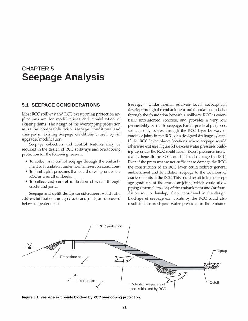
CHAPTER 5
Seepage Analysis
5.1 SEEPAGE CONSIDERATIONS
Most RCC spillway and RCC overtopping protection ap-plications are for modifications and rehabilitation ofexisting dams. The design of the overtopping protectionmust be compatible with seepage conditions andchanges in existing seepage conditions caused by anupgrade/modification.
Seepage collection and control features may berequired in the design of RCC spillways and overtoppingprotection for the following reasons:
• To collect and control seepage through the embank-ment or foundation under normal reservoir conditions.
• To limit uplift pressures that could develop under theRCC as a result of floods.
• To collect and control infiltration of water throughcracks and joints.
Seepage and uplift design considerations, which alsoaddress infiltration through cracks and joints, are discussedbelow in greater detail.
Seepage – Under normal reservoir levels, seepage candevelop through the embankment and foundation and alsothrough the foundation beneath a spillway. RCC is essen-tially unreinforced concrete, and provides a very lowpermeability barrier to seepage. For all practical purposes,seepage only passes through the RCC layer by way ofcracks or joints in the RCC, or a designed drainage system.If the RCC layer blocks locations where seepage wouldotherwise exit (see Figure 5.1), excess water pressures build-ing up under the RCC could result. Excess pressures imme-diately beneath the RCC could lift and damage the RCC.Even if the pressures are not sufficient to damage the RCC,the construction of an RCC layer could redirect generalembankment and foundation seepage to the locations ofcracks or joints in the RCC. This could result in higher seep-age gradients at the cracks or joints, which could allowpiping (internal erosion) of the embankment and/or foun-dation soil to develop, if not considered in the design.Blockage of seepage exit points by the RCC could alsoresult in increased pore water pressures in the embank-
21
RCC protection
Foundation
Riprap
CutoffPotential seepage exitpoints blocked by RCC
Embankment
Figure 5.1. Seepage exit points blocked by RCC overtopping protection.
occur. The seepage control system must also include collec-tion and outfall pipes or other means to discharge the seep-age collected in the system.
Uplift Pressures – During flood events, when water flowsover the RCC, there is a potential for pressures to build upbeneath the RCC layer. These pressures can build up in apermeable drainage layer beneath the RCC or at theboundary between the RCC and less permeable underlyingstrata (if no drainage layer is present). If the pressures thatbuild up exceed the combined weight of the overlying RCCand the water on top of the RCC, the RCC could be liftedup and damaged. Movement of the RCC layer during flowover the RCC can lead to erosion, undermining, and failureof the RCC protection.
Pressure can build up beneath RCC overtoppingthrough two sources, as shown in Figure 5.2. First, thereservoir can come into direct or near-direct communica-tion with the area under the RCC from erosion at theupstream end of the RCC. Second, water pressure can betransmitted through cracks and/or joints in the RCCduring overtopping flows. Pressure from direct communi-cation with the reservoir is of particular concern, because ofthe potential to transmit the full reservoir head to the areabeneath the RCC.
For pressures to build up under large areas of the RCCslab due to flow in the spillway, hydrostatic pressure mustbe transmitted through the cracks by infiltration, andspread laterally beneath the slab. The potential for pressurebuild up would increase as the spacing of the cracksdecrease because the distance over which the pressuremust be transmitted decreases. Consequently, an RCCdesign that results in more widely spaced cracks is lessprone to development of this potential problem.The poten-tial pressure beneath the RCC needs to be considered fornormal conditions, conditions during an overtoppingevent, and conditions immediately after overtoppingceases. The most critical conditions can occur once over-topping ceases when there will no longer be water on topof the RCC, except for tailwater from other dischargesources (e.g., a service spillway or an outlet works). If thepressure cannot drain from beneath the RCC quicklyenough, a condition could develop where pressure istrapped beneath the RCC without the gravity load fromwater on top of the RCC, and heave of the RCC couldresult. In general, heave of the RCC under these conditionswould not be as serious as uplift that occurred during over-topping, since erosion and total failure of the RCC protec-tion would not likely result. However, the RCC could bedamaged and the structure could be at risk to erosiondamage during subsequent spillway flows, before repaircan be made. The designer needs to assess how serious thispotential condition is and how it should to be addressed inthe design.
For low height dams, the weight of the RCC layer maybe sufficient to resist the full reservoir head, even at the toeof the dam. However, for higher structures, it may be
ment and foundation soil which in turn would decrease thestability of the embankment.
If the existing embankment or foundation includesadequate seepage collection and control features upstreamof the location of the RCC, then it may not be necessary toinclude seepage collection and control features in the RCCdesign. For example, if an embankment includes anupstream chimney and blanket drain, then it is not likelythat uncontrolled seepage would reach the underside of anRCC overtopping protection layer. Similarly, if an embank-ment contains an effective clay core, seepage may not reachthe downstream face where the RCC layer would beconstructed. However, in this latter case, the designershould be cautious before concluding that seepage couldnot reach the downstream face. The lack of visible seepageon the downstream slope of an existing dam may not besufficient to conclude that a drainage system may not beneeded. It is possible that the amount of seepage thatreaches the face is sufficiently small that it evaporates in theopen air, but could build up under the RCC. If the RCCprotection is constructed downstream of existing seepagecollection and control features, the design must includemeans for the discharge from those systems to safely passthrough or around the RCC. Visual observations, designdocuments, and record drawings for an existing damshould not be used as the sole basis for excluding seepagecollection and control features from an RCC protectiondesign. Rather, it is recommended that field investigationsand instrumentation readings be used to confirm the actualseepage condition in the embankment and foundationbefore that decision is made.
Normally dry flood control dams can be a special casewith respect to seepage considerations. If the embankmentmaterial is sufficiently low in permeability and/or the damserves exclusively for storm detention, there may be insuf-ficient time for seepage to develop through the dam. Thiscase can be analyzed by a transient seepage analysis.However, in considering this case, the designer must alsoevaluate the effects of defects or design details (e.g., cracksin the embankment, pervious foundation layers) for thetransient analysis.
If the designer decides that a complete seepage collec-tion and control system is not required beneath the RCCovertopping protection for seepage under normal poolconditions, it may be advisable to include a geotextile orfilter zone immediately beneath the RCC to control thepotential for loss of fines through cracks or joints fromsurface water runoff or overtopping flows. In addition, aseepage collection and control system may be requiredbecause of uplift considerations, as discussed below.
The most common method used to control seepage foran RCC spillway or overtopping design is a drainage layerplaced underneath the RCC layer. The drainage layer mustprovide sufficient capacity to convey the anticipated seep-age (plus a margin of safety), and it must meet filter crite-ria relative to the underlying soils so that piping does not
22
Design Manual for RCC Spillways and Overtopping Protection • EB218
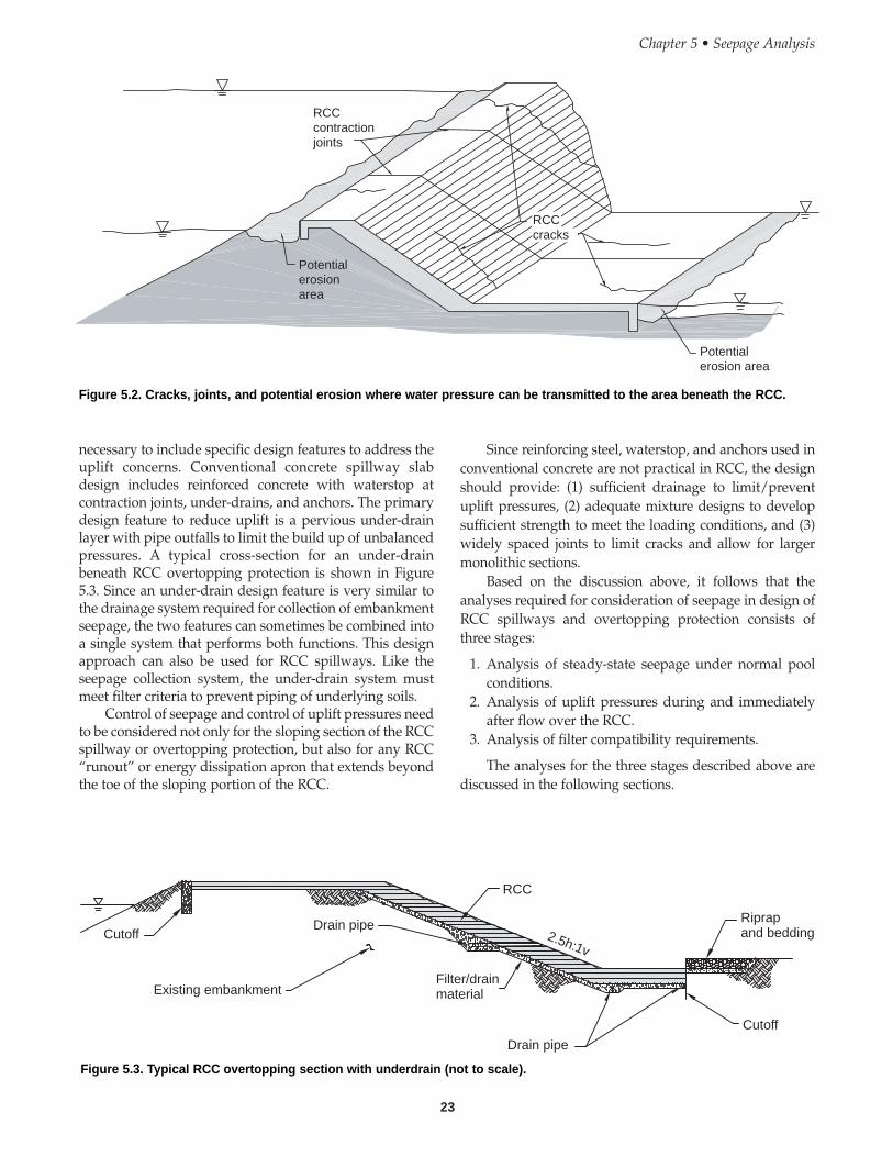
necessary to include specific design features to address theuplift concerns. Conventional concrete spillway slabdesign includes reinforced concrete with waterstop atcontraction joints, under-drains, and anchors. The primarydesign feature to reduce uplift is a pervious under-drainlayer with pipe outfalls to limit the build up of unbalancedpressures. A typical cross-section for an under-drainbeneath RCC overtopping protection is shown in Figure5.3. Since an under-drain design feature is very similar tothe drainage system required for collection of embankmentseepage, the two features can sometimes be combined intoa single system that performs both functions. This designapproach can also be used for RCC spillways. Like theseepage collection system, the under-drain system mustmeet filter criteria to prevent piping of underlying soils.
Control of seepage and control of uplift pressures needto be considered not only for the sloping section of the RCCspillway or overtopping protection, but also for any RCC“runout” or energy dissipation apron that extends beyondthe toe of the sloping portion of the RCC.
Since reinforcing steel, waterstop, and anchors used inconventional concrete are not practical in RCC, the designshould provide: (1) sufficient drainage to limit/preventuplift pressures, (2) adequate mixture designs to developsufficient strength to meet the loading conditions, and (3)widely spaced joints to limit cracks and allow for largermonolithic sections.
Based on the discussion above, it follows that theanalyses required for consideration of seepage in design ofRCC spillways and overtopping protection consists ofthree stages:
1. Analysis of steady-state seepage under normal poolconditions.
2. Analysis of uplift pressures during and immediatelyafter flow over the RCC.
3. Analysis of filter compatibility requirements.
The analyses for the three stages described above arediscussed in the following sections.
23
Chapter 5 • Seepage Analysis
RCCcontractionjoints
Potentialerosion area
RCCcracks
Potentialerosionarea
Figure 5.2. Cracks, joints, and potential erosion where water pressure can be transmitted to the area beneath the RCC.
Cutoff
Existing embankment
Drain pipe
RCC
Filter/drainmaterial
Drain pipe
Cutoff
Riprapand bedding2.5h:1v
Figure 5.3. Typical RCC overtopping section with underdrain (not to scale).
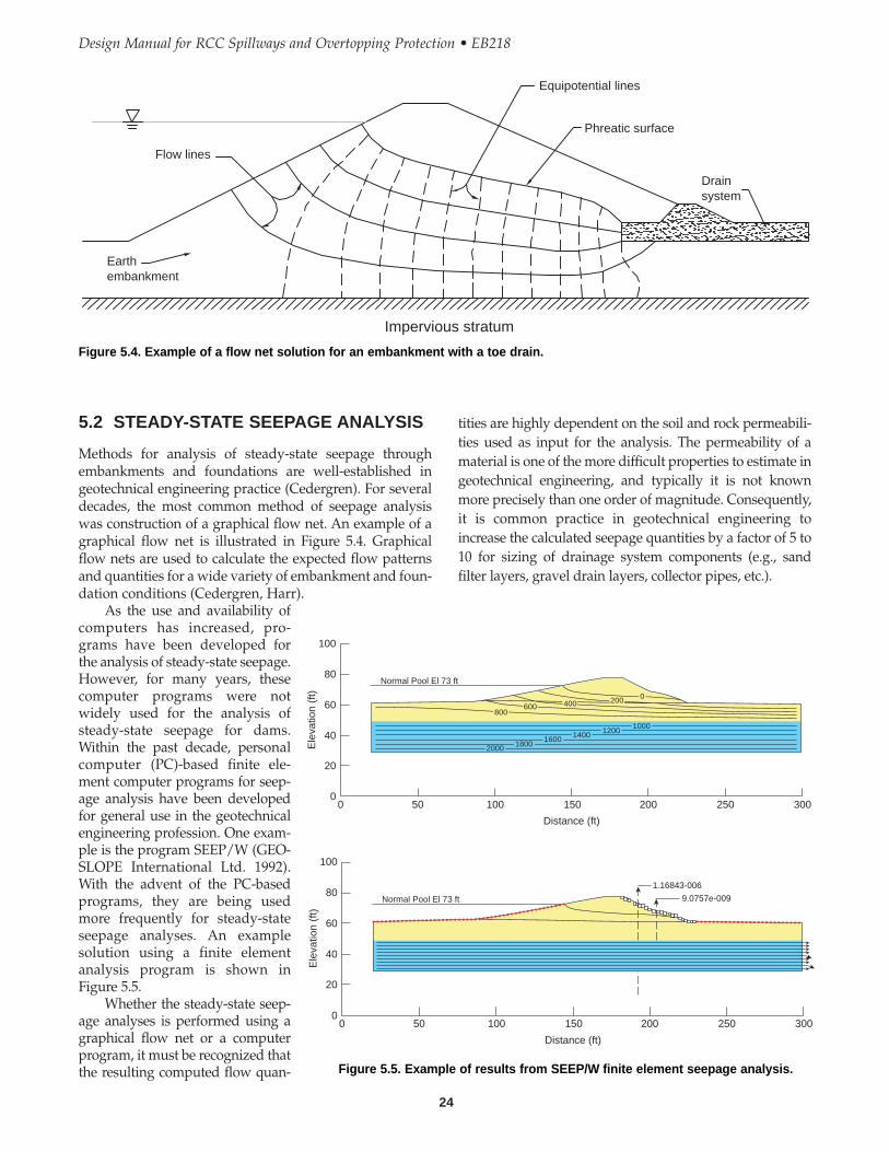
tities are highly dependent on the soil and rock permeabili-ties used as input for the analysis. The permeability of amaterial is one of the more difficult properties to estimate ingeotechnical engineering, and typically it is not knownmore precisely than one order of magnitude. Consequently,it is common practice in geotechnical engineering toincrease the calculated seepage quantities by a factor of 5 to10 for sizing of drainage system components (e.g., sandfilter layers, gravel drain layers, collector pipes, etc.).
5.2 STEADY-STATE SEEPAGE ANALYSIS
Methods for analysis of steady-state seepage throughembankments and foundations are well-established ingeotechnical engineering practice (Cedergren). For severaldecades, the most common method of seepage analysiswas construction of a graphical flow net. An example of agraphical flow net is illustrated in Figure 5.4. Graphicalflow nets are used to calculate the expected flow patternsand quantities for a wide variety of embankment and foun-dation conditions (Cedergren, Harr).
As the use and availability ofcomputers has increased, pro-grams have been developed forthe analysis of steady-state seepage.However, for many years, thesecomputer programs were notwidely used for the analysis ofsteady-state seepage for dams.Within the past decade, personalcomputer (PC)-based finite ele-ment computer programs for seep-age analysis have been developedfor general use in the geotechnicalengineering profession. One exam-ple is the program SEEP/W (GEO-SLOPE International Ltd. 1992).With the advent of the PC-basedprograms, they are being usedmore frequently for steady-stateseepage analyses. An examplesolution using a finite elementanalysis program is shown inFigure 5.5.
Whether the steady-state seep-age analyses is performed using agraphical flow net or a computerprogram, it must be recognized thatthe resulting computed flow quan-
24
Design Manual for RCC Spillways and Overtopping Protection • EB218
100
80
60
40
20
00 50 100 150 200 250 300
Distance (ft)
Ele
vatio
n (f
t)
Normal Pool El 73 ft
2000 18001600 1400 1200
1000
800600 400 200 0
100
80
60
40
20
00 50 100 150 200 250 300
Distance (ft)
Ele
vatio
n (f
t)
Normal Pool El 73 ft
1.16843-006
9.0757e-009
Figure 5.5. Example of results from SEEP/W finite element seepage analysis.
Flow lines
Earthembankment
Equipotential lines
Phreatic surface
Drainsystem
Impervious stratum
Figure 5.4. Example of a flow net solution for an embankment with a toe drain.

RCC spillways and overtopping protection are oftenused for modifications to existing dams. In many cases forexisting structures, seepage performance data is availablein the form of piezometer readings and weir flow readings(or other measurements of seepage quantities). When exist-ing data is available or instrumentation can be installed tocollect the necessary data, the seepage analysis modelshould be calibrated to be consistent with this known datafor existing conditions before the model is modified andused for design of dam modifications.
5.3 ANALYSIS OF UPLIFT PRESSURES
Unlike the case of steady-state seepage through anembankment, the method of analysis for uplift beneaththe RCC is not well established. The physics of the prob-lem is simple, as illustrated in Figure 5.6. The combinedweight of the RCC mass and the water on top of the RCCmust be sufficient to resist the uplift pressure beneath theRCC. The weight of the RCC is relatively easy to calculate.
However, there are significant uncertainties in the calcu-lation of the depth of water on top of the RCC and espe-cially in predicting the water pressure that could developbeneath the RCC.
The depth of water on top of the RCC would typicallybe calculated using water surface profile models, which issubject to the uncertainty inherent in those analyses. Thedepth of water during maximum overtopping would becalculated using a steady-state water surface profile analy-sis. The depth of water on top of the RCC as the floodrecedes would need to be calculated using a transient watersurface profile and would be affected by the degree of accu-racy of knowledge of the inflow flood hydrograph and thedownstream conditions that would control tailwater.
The water pressure beneath the RCC is the result oftransient flow and seepage conditions. The conditions lead-ing to water pressure beneath the RCC are: (1) water canpass through cracks or joints in the RCC as water flowsover the layer; (2) water can seep through the embankmentor foundation to a wide area beneath the RCC if the over-topping duration is long, and (3) if erosion occurs at theupstream end of the RCC, then seepage or infiltration canmore easily occur beneath the RCC. As a flood abates, thereservoir level and the depth of water on top of the RCCwill reduce. At the same time, the pressures beneath theRCC will begin to dissipate by flow out through cracks orjoints, and flow through any under-drain system beneaththe RCC. The dissipation of the pressures is a transientseepage problem, which can be analyzed by computer-based programs. However, in geotechnical engineering, thedegree of accuracy of transient analyses of seepage is lessthan that of steady-state seepage analyses.
Because of the uncertainty in the analyses, the upliftcondition is not often analyzed in detail. Instead, this ques-tion is often addressed by geotechnical engineers usingsimplified analysis models and judgment. One approachused within the profession is that the pressures beneath theRCC cannot be sustained significantly above the level ofthe water on top of the RCC, because of the hydrauliccommunication provided by cracks and joints in the RCC.Following this school of thought, unbalanced uplift pres-sures would not build up significantly and no specialdesign features would be needed to address this concern.Another approach suggests that high pressures will buildup in the RCC during overtopping and may not drainquickly, unless the RCC is underlain by a relatively highcapacity drainage system (e.g., a gravel drainage layer).
Few RCC spillways or overtopping protection installa-tions have been tested by significant flows, so at this time itis not known which of these approaches is most represen-tative of the field conditions. It is likely that more appro-priate analysis methods will be developed as installedsystems are tested by overtopping events. In the interim, itis left to each designer to evaluate this issue and analyze itas they see fit. Since cracks in the RCC provide a potentialpath for seepage that could lead to uplift pressures, the
25
Chapter 5 • Seepage Analysis
RCC
Uplift occurs if PV > WR + WW
PV
PH
WR
WR = Weight of RCCWW = Weight of water above RCCPR = Water pressure beneath RCCPV = Vertical component of PPH = Horizontal component of P
WW
P
Water pressure beneath RCC
Fig. 5.6. Physics of uplift for RCC overtopping protection.

RCC should be designed to produce as few cracks andjoints, as widely spaced, as practical.
Until better methods of analysis are developed, it isrecommended that RCC spillways and overtopping protec-tion installations include under-drains or pressure relief sys-tems spaced approximately every 10 vertical feet. Typicaldetails for an under-drain system are illustrated in Figure5.7. Pipe drains that extend through sloping RCC sectionsshould be designed to provide aspiration at the outlet end,so that they drain properly during flow over the RCC.
Pressure relief systems should also be includedbeneath horizontal runout or energy dissipation sectionslocated at the downstream ends of the spillways and over-topping protection sections, as is customarily done withspillway stilling basins.
5.4 ANALYSIS OF FILTERCOMPATIBILITY
Methods for analysis of filter compatibility are well estab-lished in the geotechnical engineering profession, andcomprehensive criteria have been published by numerousorganizations (U.S. Department of Agriculture, SoilConservation Service, October 1994; USACE 1993; U.S.Department of Interior, Bureau of Reclamation, June 28,1999). The specific criteria are not repeated herein.
In principle, filter compatibility guidelines were devel-oped to provide criteria to design a filter layer composed ofsoil with a grain size distribution which results in porespaces that are small enough to prevent movement of soilparticles from the “base” soil (embankment or foundationmaterial) that is being filtered. When a filter is placed
against a base embankment or foundation soil that variesin gradation, the filter must provide adequate protection tothe finer grained soil. If a drainage system contains multi-ple layers (e.g., sand filters and gravel drains), then filtercriteria must be met at each successive boundary. Forexample, the sand filter would need to provide adequateprotection to base embankment or foundation soil, and thegravel would need to provide protection to the base sandfilter. Similarly, if the drainage system includes slotted orperforated collection pipes, the slots or perforations wouldneed to provide filter compatibility with the immediatelysurrounding soil. Published criteria for filter compatibilityof slots and perforations are provided in the referencesnoted above.
Filter compatibility must also be addressed for thematerial beneath cracks through the RCC. If the soilbeneath the cracks is fine enough, relative to the width ofthe crack, then the soil can be washed out by flow throughthe crack. Flow through the crack could result from steady-state seepage, the release of water that infiltrated under theslab during overtopping or from precipitation events. Iffine grain soils or fine sand filter material is in directcontact with the RCC and cracks are expected to occur inthe RCC, then a geotextile should be considered as a filterlayer directly beneath the RCC. Steady-state seepage ismost critical of the sources because the sustained durationseepage from this condition could lead to a piping failureof the embankment over the long term, if left uncontrolled.However, loss of soil from the other two sources could leadto formation of voids under the RCC, which could still be asignificant problem. Filter compatibility beneath a crackshould be analyzed using the same methods used for slot-ted pipes, as described above.
26
Design Manual for RCC Spillways and Overtopping Protection • EB218
Filter/drainmaterial
Soliddischarge pipe
Trim end of pipe flush withface of step. Install screenat outfall.
Slotted pipe
RCC
2.5h:1v
Figure 5.7. Typical details of an underdrain and outlet pipe.
Geotextiles have been used to serve the filter functionin some RCC spillway and overtopping protection applica-tions. However, the designer should be cautious in the useof geotextiles in this application because they will beisolated underneath the RCC, and therefore, difficult toaccess for repair or replacement. The history of the use ofgeotextiles for these types of applications is short, relativeto the experience with soil filters. The potential for long-term deterioration or plugging of geotextiles is yet to befirmly established. Until the long-term performance ofgeotextiles in dam applications is better established, it isnot recommended that geotextiles be used in an applica-tion where their function is critical to dam safety. Non-crit-ical applications may be reasonable, subject to con-sideration of the limited access to the geotextile for repairor replacement in the future.
27
Chapter 1 • RCC Spillways and Overtopping Protection

28
Design Manual for RCC Spillways and Overtopping Protection • EB218
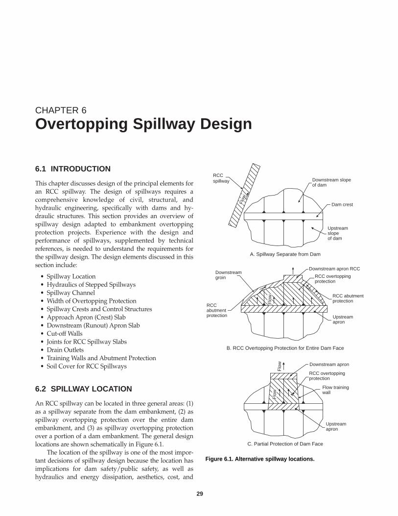
CHAPTER 6
Overtopping Spillway Design
6.1 INTRODUCTION
This chapter discusses design of the principal elements foran RCC spillway. The design of spillways requires acomprehensive knowledge of civil, structural, andhydraulic engineering, specifically with dams and hy-draulic structures. This section provides an overview ofspillway design adapted to embankment overtoppingprotection projects. Experience with the design andperformance of spillways, supplemented by technicalreferences, is needed to understand the requirements forthe spillway design. The design elements discussed in thissection include:
• Spillway Location• Hydraulics of Stepped Spillways• Spillway Channel• Width of Overtopping Protection• Spillway Crests and Control Structures• Approach Apron (Crest) Slab• Downstream (Runout) Apron Slab• Cut-off Walls• Joints for RCC Spillway Slabs• Drain Outlets• Training Walls and Abutment Protection• Soil Cover for RCC Spillways
6.2 SPILLWAY LOCATION
An RCC spillway can be located in three general areas: (1)as a spillway separate from the dam embankment, (2) asspillway overtopping protection over the entire damembankment, and (3) as spillway overtopping protectionover a portion of a dam embankment. The general designlocations are shown schematically in Figure 6.1.
The location of the spillway is one of the most impor-tant decisions of spillway design because the location hasimplications for dam safety/public safety, as well ashydraulics and energy dissipation, aesthetics, cost, and
29
RCCspillway Downstream slope
of dam
Dam crest
Upstreamslopeof dam
Downstreamgroin
Downstream apron RCC
RCC overtoppingprotection
RCCabutmentprotection
RCC abutmentprotection
Upstreamapron
Downstream apron
RCC overtoppingprotection
Flow trainingwall
Upstreamapron
Flo
wF
low
Flo
w
Flow
A. Spillway Separate from Dam
B. RCC Overtopping Protection for Entire Dam Face
C. Partial Protection of Dam Face
Figure 6.1. Alternative spillway locations.
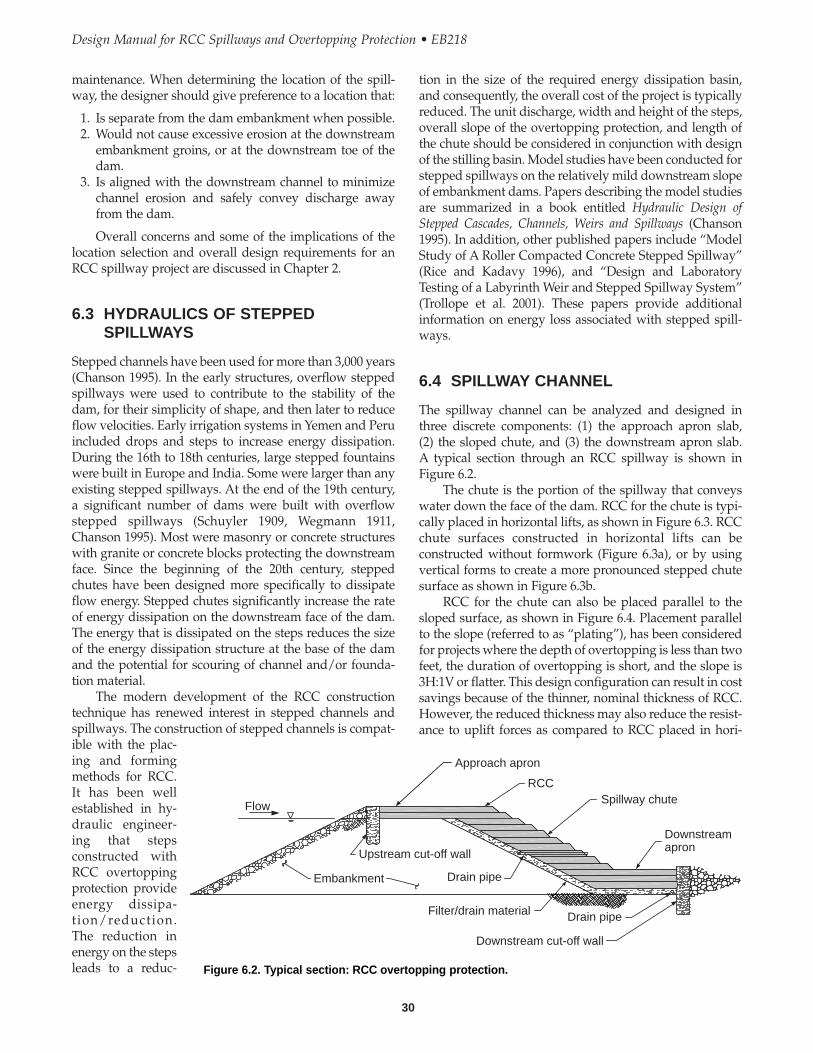
tion in the size of the required energy dissipation basin,and consequently, the overall cost of the project is typicallyreduced. The unit discharge, width and height of the steps,overall slope of the overtopping protection, and length ofthe chute should be considered in conjunction with designof the stilling basin. Model studies have been conducted forstepped spillways on the relatively mild downstream slopeof embankment dams. Papers describing the model studiesare summarized in a book entitled Hydraulic Design ofStepped Cascades, Channels, Weirs and Spillways (Chanson1995). In addition, other published papers include “ModelStudy of A Roller Compacted Concrete Stepped Spillway”(Rice and Kadavy 1996), and “Design and LaboratoryTesting of a Labyrinth Weir and Stepped Spillway System”(Trollope et al. 2001). These papers provide additionalinformation on energy loss associated with stepped spill-ways.
6.4 SPILLWAY CHANNEL
The spillway channel can be analyzed and designed inthree discrete components: (1) the approach apron slab,(2) the sloped chute, and (3) the downstream apron slab.A typical section through an RCC spillway is shown inFigure 6.2.
The chute is the portion of the spillway that conveyswater down the face of the dam. RCC for the chute is typi-cally placed in horizontal lifts, as shown in Figure 6.3. RCCchute surfaces constructed in horizontal lifts can beconstructed without formwork (Figure 6.3a), or by usingvertical forms to create a more pronounced stepped chutesurface as shown in Figure 6.3b.
RCC for the chute can also be placed parallel to thesloped surface, as shown in Figure 6.4. Placement parallelto the slope (referred to as “plating”), has been consideredfor projects where the depth of overtopping is less than twofeet, the duration of overtopping is short, and the slope is3H:1V or flatter. This design configuration can result in costsavings because of the thinner, nominal thickness of RCC.However, the reduced thickness may also reduce the resist-ance to uplift forces as compared to RCC placed in hori-
maintenance. When determining the location of the spill-way, the designer should give preference to a location that:
1. Is separate from the dam embankment when possible.2. Would not cause excessive erosion at the downstream
embankment groins, or at the downstream toe of thedam.
3. Is aligned with the downstream channel to minimizechannel erosion and safely convey discharge awayfrom the dam.
Overall concerns and some of the implications of thelocation selection and overall design requirements for anRCC spillway project are discussed in Chapter 2.
6.3 HYDRAULICS OF STEPPEDSPILLWAYS
Stepped channels have been used for more than 3,000 years(Chanson 1995). In the early structures, overflow steppedspillways were used to contribute to the stability of thedam, for their simplicity of shape, and then later to reduceflow velocities. Early irrigation systems in Yemen and Peruincluded drops and steps to increase energy dissipation.During the 16th to 18th centuries, large stepped fountainswere built in Europe and India. Some were larger than anyexisting stepped spillways. At the end of the 19th century,a significant number of dams were built with overflowstepped spillways (Schuyler 1909, Wegmann 1911,Chanson 1995). Most were masonry or concrete structureswith granite or concrete blocks protecting the downstreamface. Since the beginning of the 20th century, steppedchutes have been designed more specifically to dissipateflow energy. Stepped chutes significantly increase the rateof energy dissipation on the downstream face of the dam.The energy that is dissipated on the steps reduces the sizeof the energy dissipation structure at the base of the damand the potential for scouring of channel and/or founda-tion material.
The modern development of the RCC constructiontechnique has renewed interest in stepped channels andspillways. The construction of stepped channels is compat-ible with the plac-ing and formingmethods for RCC.It has been wellestablished in hy-draulic engineer-ing that stepsconstructed withRCC overtoppingprotection provideenergy dissipa-t ion/reduction.The reduction inenergy on the stepsleads to a reduc-
30
Design Manual for RCC Spillways and Overtopping Protection • EB218
Flow
Approach apron
RCCSpillway chute
Downstreamapron
Embankment
Upstream cut-off wall
Drain pipe
Filter/drain material
Downstream cut-off wall
Drain pipe
Figure 6.2. Typical section: RCC overtopping protection.
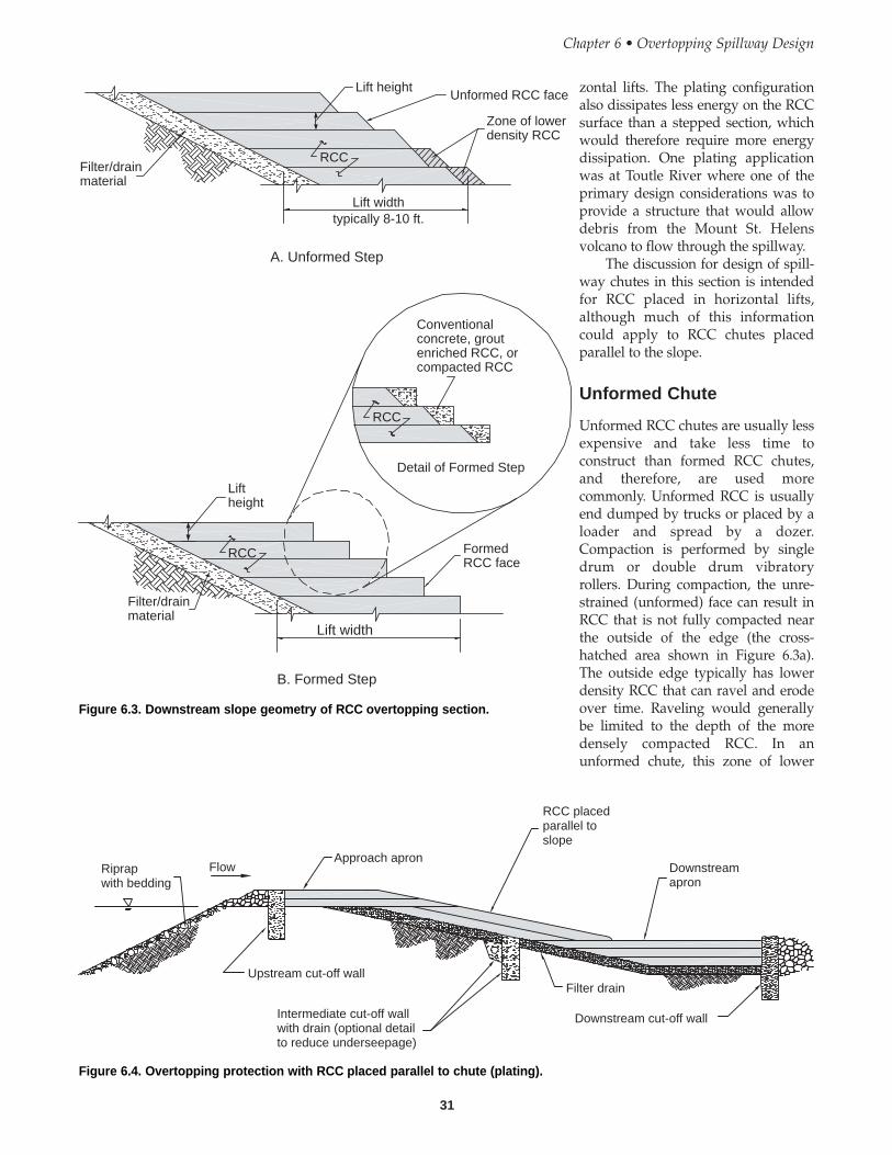
31
zontal lifts. The plating configurationalso dissipates less energy on the RCCsurface than a stepped section, whichwould therefore require more energydissipation. One plating applicationwas at Toutle River where one of theprimary design considerations was toprovide a structure that would allowdebris from the Mount St. Helensvolcano to flow through the spillway.
The discussion for design of spill-way chutes in this section is intendedfor RCC placed in horizontal lifts,although much of this informationcould apply to RCC chutes placedparallel to the slope.
Unformed Chute
Unformed RCC chutes are usually lessexpensive and take less time toconstruct than formed RCC chutes,and therefore, are used morecommonly. Unformed RCC is usuallyend dumped by trucks or placed by aloader and spread by a dozer.Compaction is performed by singledrum or double drum vibratoryrollers. During compaction, the unre-strained (unformed) face can result inRCC that is not fully compacted nearthe outside of the edge (the cross-hatched area shown in Figure 6.3a).The outside edge typically has lowerdensity RCC that can ravel and erodeover time. Raveling would generallybe limited to the depth of the moredensely compacted RCC. In anunformed chute, this zone of lower
Chapter 6 • Overtopping Spillway Design
Filter/drainmaterial
Lift heightUnformed RCC face
Zone of lowerdensity RCC
Lift widthtypically 8-10 ft.
RCC
RCC
RCC
Conventionalconcrete, groutenriched RCC, orcompacted RCC
Detail of Formed Step
Liftheight
FormedRCC face
Filter/drainmaterial
Lift width
A. Unformed Step
B. Formed Step
Figure 6.3. Downstream slope geometry of RCC overtopping section.
FlowRiprapwith bedding
Approach apron
RCC placedparallel toslope
Downstreamapron
Upstream cut-off wall
Intermediate cut-off wallwith drain (optional detailto reduce underseepage)
Filter drain
Downstream cut-off wall
Figure 6.4. Overtopping protection with RCC placed parallel to chute (plating).
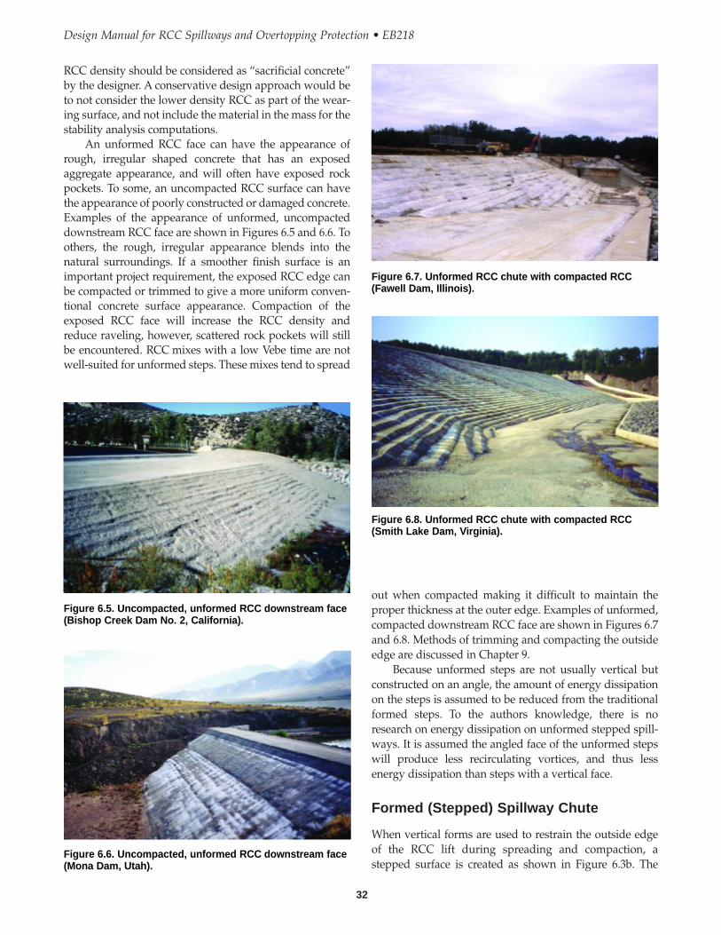
32
Design Manual for RCC Spillways and Overtopping Protection • EB218
out when compacted making it difficult to maintain theproper thickness at the outer edge. Examples of unformed,compacted downstream RCC face are shown in Figures 6.7and 6.8. Methods of trimming and compacting the outsideedge are discussed in Chapter 9.
Because unformed steps are not usually vertical butconstructed on an angle, the amount of energy dissipationon the steps is assumed to be reduced from the traditionalformed steps. To the authors knowledge, there is noresearch on energy dissipation on unformed stepped spill-ways. It is assumed the angled face of the unformed stepswill produce less recirculating vortices, and thus lessenergy dissipation than steps with a vertical face.
Formed (Stepped) Spillway Chute
When vertical forms are used to restrain the outside edgeof the RCC lift during spreading and compaction, astepped surface is created as shown in Figure 6.3b. The
RCC density should be considered as “sacrificial concrete”by the designer. A conservative design approach would beto not consider the lower density RCC as part of the wear-ing surface, and not include the material in the mass for thestability analysis computations.
An unformed RCC face can have the appearance ofrough, irregular shaped concrete that has an exposedaggregate appearance, and will often have exposed rockpockets. To some, an uncompacted RCC surface can havethe appearance of poorly constructed or damaged concrete.Examples of the appearance of unformed, uncompacteddownstream RCC face are shown in Figures 6.5 and 6.6. Toothers, the rough, irregular appearance blends into thenatural surroundings. If a smoother finish surface is animportant project requirement, the exposed RCC edge canbe compacted or trimmed to give a more uniform conven-tional concrete surface appearance. Compaction of theexposed RCC face will increase the RCC density andreduce raveling, however, scattered rock pockets will stillbe encountered. RCC mixes with a low Vebe time are notwell-suited for unformed steps. These mixes tend to spread
Figure 6.6. Uncompacted, unformed RCC downstream face(Mona Dam, Utah).
Figure 6.5. Uncompacted, unformed RCC downstream face(Bishop Creek Dam No. 2, California).
Figure 6.7. Unformed RCC chute with compacted RCC(Fawell Dam, Illinois).
Figure 6.8. Unformed RCC chute with compacted RCC(Smith Lake Dam, Virginia).
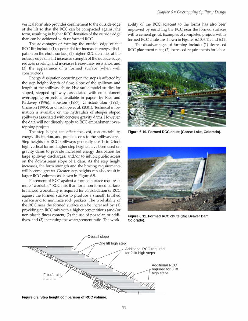
33
vertical form also provides confinement to the outside edgeof the lift so that the RCC can be compacted against theform, resulting in higher RCC densities of the outside edgethan can be achieved with unformed RCC.
The advantages of forming the outside edge of theRCC lift include: (1) a potential for increased energy dissi-pation on the chute surface; (2) higher RCC densities at theoutside edge of a lift increases strength of the outside edge,reduces raveling, and increases freeze-thaw resistance; and(3) the appearance of a formed surface (when wellconstructed).
Energy dissipation occurring on the steps is affected bythe step height, depth of flow, slope of the spillway, andlength of the spillway chute. Hydraulic model studies forsloped, stepped spillways associated with embankmentovertopping projects is available in papers by Rice andKadavey (1996), Houston (1987), Christodoulou (1993),Chanson (1995), and Trollope et al. (2001). Technical infor-mation is available on the hydraulics of steeper slopedspillways associated with concrete gravity dams. However,the data will not directly apply to RCC embankment over-topping projects.
The step height can affect the cost, constructability,energy dissipation, and public access to the spillway area.Step heights for RCC spillways generally use 1- to 2-foothigh vertical forms. Higher step heights have been used ongravity dams to provide increased energy dissipation forlarge spillway discharges, and/or to inhibit public accesson the downstream slope of a dam. As the step heightincreases, the form strength and the bracing requirementswill become greater. Greater step heights can also result inlarger RCC volumes as shown in Figure 6.9.
Placement of RCC against a formed surface requires amore “workable” RCC mix than for a non-formed surface.Enhanced workability is required for consolidation of RCCagainst the formed surface to produce a smooth finishedsurface and to minimize rock pockets. The workability ofthe RCC near the formed surface can be increased by: (1)providing an RCC mix with a higher cementitious (and/ornon-plastic fines) content, (2) the use of pozzolan or addi-tives, and (3) increasing the water/cement ratio. The work-
ability of the RCC adjacent to the forms has also beenimproved by enriching the RCC near the formed surfaceswith a cement grout. Examples of completed projects with aformed RCC chute are shown in Figures 6.10, 6.11, and 6.12.
The disadvantages of forming include: (1) decreasedRCC placement rates; (2) increased requirements for labor-
Chapter 6 • Overtopping Spillway Design
Overall slope
One lift high step
Additional RCC requiredfor 2 lift high steps
Additional RCCrequired for 3 lifthigh stepsFilter/drain
material
Figure 6.9. Step height comparison of RCC volume.
Figure 6.10. Formed RCC chute (Goose Lake, Colorado).
Figure 6.11. Formed RCC chute (Big Beaver Dam,Colorado).
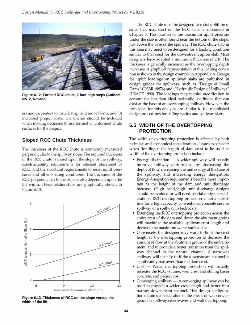
34
Design Manual for RCC Spillways and Overtopping Protection • EB218
ers and carpenters to install, strip, and move forms; and (3)increased project costs. The Owner should be includedwhen making decisions to use formed or unformed chutesurfaces for the project.
Sloped RCC Chute Thickness
The thickness of the RCC chute is commonly measuredperpendicular to the spillway slope. The required thicknessof the RCC chute is based upon the slope of the spillway,constructability requirements for efficient placement ofRCC, and the structural requirements to resist uplift pres-sures and other loading conditions. The thickness of theRCC perpendicular to the slope is also dependent upon thelift width. These relationships are graphically shown inFigure 6.13.
Figure 6.12. Formed RCC chute, 2 foot high steps (AnthemNo. 2, Nevada).
2:1 slope
4:1 slope
3:1 slope
5
4
3
2
8 9 10 11
Lift
Thic
knes
s N
orm
al to
Slo
pe (f
t.)
Horizontal Placement Width (ft.)
Figure 6.13. Thickness of RCC on the slope versus thewidth of the lift.
The RCC chute must be designed to resist uplift pres-sures that may exist on the RCC slab, as discussed inChapter 5. The location of the maximum uplift pressureunder the slab is often found near the bottom of the slope,just above the base of the spillway. The RCC chute slab inthis area may need to be designed for a loading conditionsimilar to that used for the downstream apron slab. Mostdesigners have adapted a minimum thickness of 2 ft. Thethickness is generally increased as the overtopping depthincreases. A graphical representation of this loading condi-tion is shown in the design example in Appendix A. Designfor uplift loadings on spillway slabs are published indesign guides for spillways, such as “Design of SmallDams” (USBR 1987a) and “Hydraulic Design of Spillways”(USACE 1990). The loadings may require modification toaccount for less than ideal hydraulic conditions that canexist at the base of an overtopping spillway. However, theprinciples for this analysis are similar to the establisheddesign procedures for stilling basins and spillway slabs.
6.5 WIDTH OF THE OVERTOPPINGPROTECTION
The width of overtopping protection is affected by bothtechnical and economical considerations. Issues to considerwhen deciding n the length of dam crest to be used aswidth of the overtopping protection include:
• Energy dissipation — A wider spillway will usuallyimprove spillway performance by decreasing thedepth of flow, decreasing the unit energy at the base ofthe spillway, and increasing energy dissipation.Energy dissipation requirements become more impor-tant as the height of the dam and unit dischargeincrease. (High head/high unit discharge designsshould be avoided or will need special design consid-erations. RCC overtopping protection is not a substi-tute for a high capacity, conventional concrete servicespillway or a spillway in bedrock.)
• Extending the RCC overtopping protection across theentire crest of the dam and down the abutment groinswill maximize the available spillway crest length anddecrease the maximum water surface level.
• Conversely, the designer may want to limit the crestlength of the overtopping protection to decrease theamount of flow at the abutment groins of the embank-ment, and to provide a better transition from the spill-way channel to the natural channel. A narrowerspillway will usually fit if the downstream channel issignificantly narrower than the dam crest.
• Cost — Wider overtopping protection will usuallyincrease the RCC volume, weir crest and stilling basinconcrete, and project cost.
• Converging spillway — A converging spillway can beused to provide a wider crest length and better fit anarrow downstream channel. This design configura-tion requires consideration of the effects of wall conver-gence on spillway cross-waves and wall overtopping.
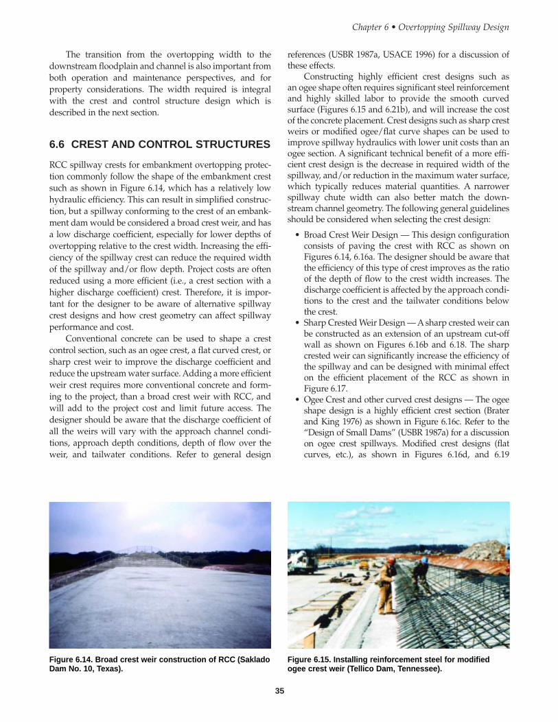
35
The transition from the overtopping width to thedownstream floodplain and channel is also important fromboth operation and maintenance perspectives, and forproperty considerations. The width required is integralwith the crest and control structure design which isdescribed in the next section.
6.6 CREST AND CONTROL STRUCTURES
RCC spillway crests for embankment overtopping protec-tion commonly follow the shape of the embankment crestsuch as shown in Figure 6.14, which has a relatively lowhydraulic efficiency. This can result in simplified construc-tion, but a spillway conforming to the crest of an embank-ment dam would be considered a broad crest weir, and hasa low discharge coefficient, especially for lower depths ofovertopping relative to the crest width. Increasing the effi-ciency of the spillway crest can reduce the required widthof the spillway and/or flow depth. Project costs are oftenreduced using a more efficient (i.e., a crest section with ahigher discharge coefficient) crest. Therefore, it is impor-tant for the designer to be aware of alternative spillwaycrest designs and how crest geometry can affect spillwayperformance and cost.
Conventional concrete can be used to shape a crestcontrol section, such as an ogee crest, a flat curved crest, orsharp crest weir to improve the discharge coefficient andreduce the upstream water surface. Adding a more efficientweir crest requires more conventional concrete and form-ing to the project, than a broad crest weir with RCC, andwill add to the project cost and limit future access. Thedesigner should be aware that the discharge coefficient ofall the weirs will vary with the approach channel condi-tions, approach depth conditions, depth of flow over theweir, and tailwater conditions. Refer to general design
references (USBR 1987a, USACE 1996) for a discussion ofthese effects.
Constructing highly efficient crest designs such asan ogee shape often requires significant steel reinforcementand highly skilled labor to provide the smooth curvedsurface (Figures 6.15 and 6.21b), and will increase the costof the concrete placement. Crest designs such as sharp crestweirs or modified ogee/flat curve shapes can be used toimprove spillway hydraulics with lower unit costs than anogee section. A significant technical benefit of a more effi-cient crest design is the decrease in required width of thespillway, and/or reduction in the maximum water surface,which typically reduces material quantities. A narrowerspillway chute width can also better match the down-stream channel geometry. The following general guidelinesshould be considered when selecting the crest design:
• Broad Crest Weir Design — This design configurationconsists of paving the crest with RCC as shown onFigures 6.14, 6.16a. The designer should be aware thatthe efficiency of this type of crest improves as the ratioof the depth of flow to the crest width increases. Thedischarge coefficient is affected by the approach condi-tions to the crest and the tailwater conditions belowthe crest.
• Sharp Crested Weir Design — A sharp crested weir canbe constructed as an extension of an upstream cut-offwall as shown on Figures 6.16b and 6.18. The sharpcrested weir can significantly increase the efficiency ofthe spillway and can be designed with minimal effecton the efficient placement of the RCC as shown inFigure 6.17.
• Ogee Crest and other curved crest designs — The ogeeshape design is a highly efficient crest section (Braterand King 1976) as shown in Figure 6.16c. Refer to the“Design of Small Dams” (USBR 1987a) for a discussionon ogee crest spillways. Modified crest designs (flatcurves, etc.), as shown in Figures 6.16d, and 6.19
Chapter 6 • Overtopping Spillway Design
Figure 6.14. Broad crest weir construction of RCC (SakladoDam No. 10, Texas).
Figure 6.15. Installing reinforcement steel for modifiedogee crest weir (Tellico Dam, Tennessee).

36
Design Manual for RCC Spillways and Overtopping Protection • EB218
Flow
Flow
RCC
Flow
Flow
DischargecoefficientC 3.60
DischargecoefficientC 3.90
DischargecoefficientC = varies(typically3.1 to 3.6)
DischargecoefficientC 2.60
Conventionalconcrete
RCC RCC
RCC
RCC
Conventionalconcrete
Conventionalconcrete
A. Broad Crested Weir
B. Sharp Crested Weir
C. Ogee Crest Weir
D. Flat Curved Crest
11
r
Figure 6.16. Alternative weir crest shapes.
Figure 6.17. Sharp crest weir wall under construction(Smith Lake Dam, Virginia).
Figure 6.18. Sharp crest weir and with completed RCCovertopping section (Smith Lake Dam, Virginia).
Figure 6.19. Sloping ogee crest weir constructed withconventional concrete (Windmill Wash, Nevada).
Figure 6.20a. Modified ogee crest weir (Coal Ridge,Colorado).
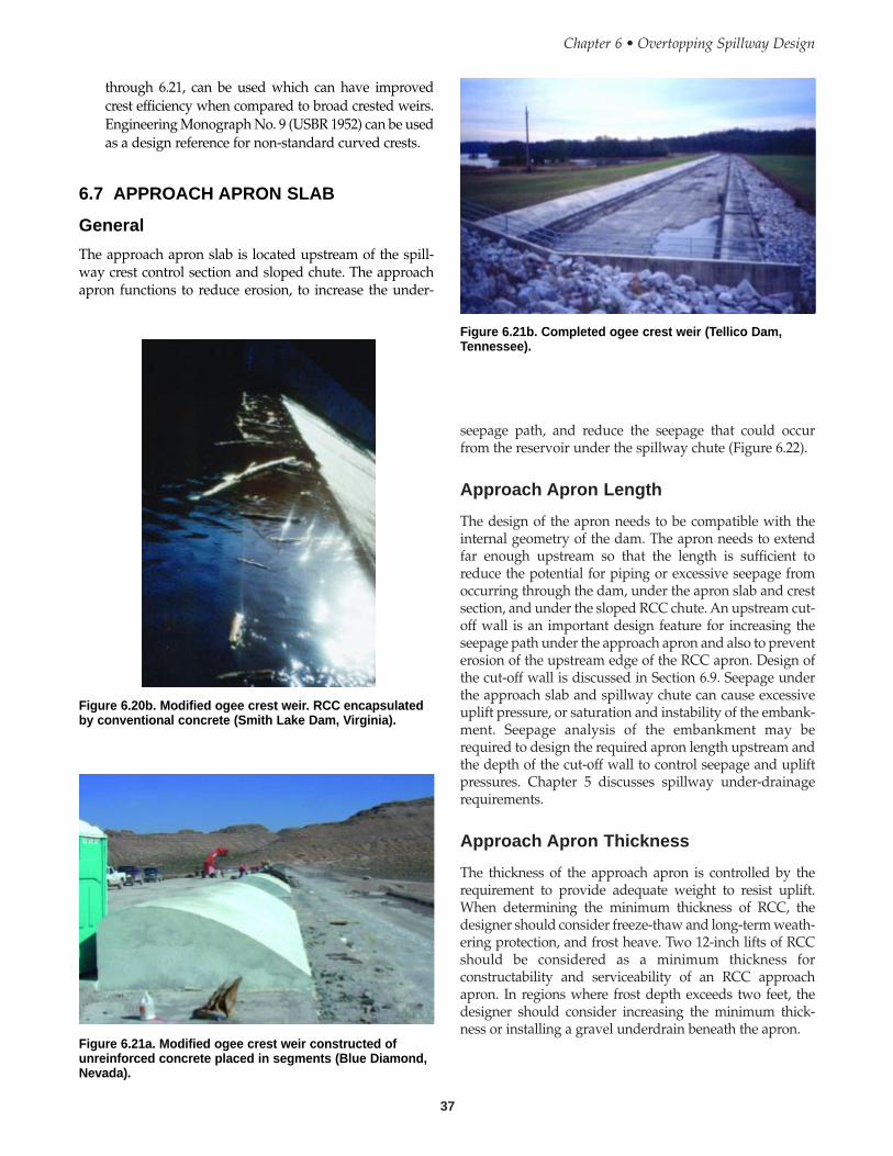
37
seepage path, and reduce the seepage that could occurfrom the reservoir under the spillway chute (Figure 6.22).
Approach Apron Length
The design of the apron needs to be compatible with theinternal geometry of the dam. The apron needs to extendfar enough upstream so that the length is sufficient toreduce the potential for piping or excessive seepage fromoccurring through the dam, under the apron slab and crestsection, and under the sloped RCC chute. An upstream cut-off wall is an important design feature for increasing theseepage path under the approach apron and also to preventerosion of the upstream edge of the RCC apron. Design ofthe cut-off wall is discussed in Section 6.9. Seepage underthe approach slab and spillway chute can cause excessiveuplift pressure, or saturation and instability of the embank-ment. Seepage analysis of the embankment may berequired to design the required apron length upstream andthe depth of the cut-off wall to control seepage and upliftpressures. Chapter 5 discusses spillway under-drainagerequirements.
Approach Apron Thickness
The thickness of the approach apron is controlled by therequirement to provide adequate weight to resist uplift.When determining the minimum thickness of RCC, thedesigner should consider freeze-thaw and long-term weath-ering protection, and frost heave. Two 12-inch lifts of RCCshould be considered as a minimum thickness forconstructability and serviceability of an RCC approachapron. In regions where frost depth exceeds two feet, thedesigner should consider increasing the minimum thick-ness or installing a gravel underdrain beneath the apron.
Chapter 6 • Overtopping Spillway Design
Figure 6.20b. Modified ogee crest weir. RCC encapsulatedby conventional concrete (Smith Lake Dam, Virginia).
Figure 6.21a. Modified ogee crest weir constructed ofunreinforced concrete placed in segments (Blue Diamond,Nevada).
Figure 6.21b. Completed ogee crest weir (Tellico Dam,Tennessee).
through 6.21, can be used which can have improvedcrest efficiency when compared to broad crested weirs.Engineering Monograph No. 9 (USBR 1952) can be usedas a design reference for non-standard curved crests.
6.7 APPROACH APRON SLAB
General
The approach apron slab is located upstream of the spill-way crest control section and sloped chute. The approachapron functions to reduce erosion, to increase the under-

38
Design Manual for RCC Spillways and Overtopping Protection • EB218
determined for the full range of spillway operational flows.Estimates of degradation, scour, and erosion below a spill-way should be developed by a hydraulic engineer experi-enced in channel hydraulics. The hydraulic conditions thatoccur at the toe of the dam are usually less than ideal.Lateral flow can occur along the groins and tailwater maybe insufficient. Therefore, design aids may not be able to beused for design and physical modeling may be required.
Examples of the downstream run-out apron, and analternative stilling basin, are shown in Figures 6.23 and6.24, respectively.
Downstream Apron Thickness
The downstream apron must be designed for uplift pres-sures that are more severe than the upstream apronbecause of the high differential water pressures that mayexist at the spillway base. The designer needs to estimatethe tailwater depth at the downstream end of the apronslab, and the depth of flow at the upstream end of theapron slab, for the range of spillway discharges to evaluatethe uplift loading conditions on the downstream apron. Itis important to note that the critical uplift loading conditionoften occurs at flows less than the maximum spillway
6.8 DOWNSTREAM APRON SLAB
General
The primary function of the downstream apron is toprotect the RCC spillway and the dam embankment fromerosion caused by spillway flow. The length and thicknessof the downstream apron depends upon energy dissipationand erosion control features of the energy dissipatordesign.
The downstream apron is one of the most criticalfeatures of the RCC spillway design, especially when theRCC spillway is located over the dam embankment. Thedesigner must have a thorough understanding of the spill-way and channel hydraulics, foundation conditions for thespillway, and how the apron design protects the spillwayand dam from erosion. A conservative approach for design-ing the downstream apron is to utilize competent bedrockas the foundation. The apron can also be located atadequate depth below tailwater, and with adequate length,so that a hydraulic jump will form on the apron.
The designer must also determine the erosion potentialof the soil or rock downstream of the apron. The estimateddepth of erosion and channel degradation can then be
Flow
Shell Shell
Flow
Upstreamcut-off wall
Upstreamcut-off wall
Riprapwith bedding
Riprapwith bedding
Central core
Approach apron
Locate cut-off in impervious core zone
Spillway chute RCC
Filter/drain material
Filter/drain material
Approachapron
Locate apron and cut-off atupstream end of crest as requiredfor underseepage control
Spillway chute RCC
Homogeneous embankment dam
A. Zoned Embankment Dam
B. Homogeneous Embankment Dam
Figure 6.22. Approach aprons.
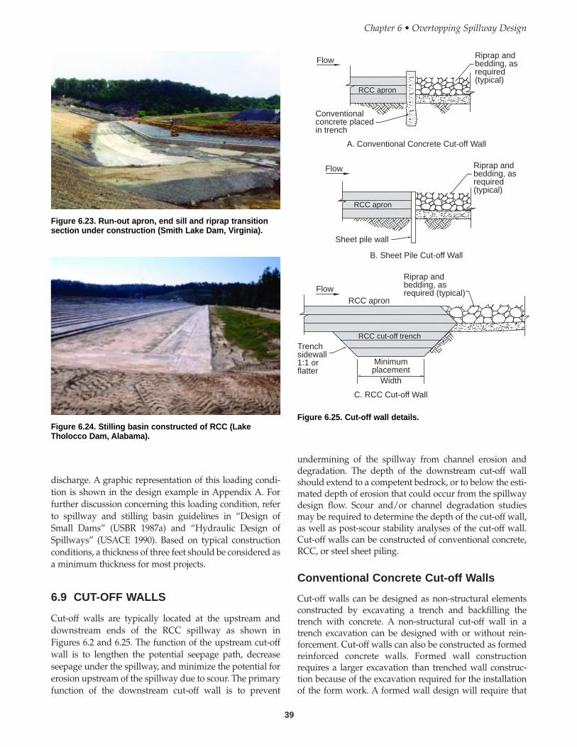
39
discharge. A graphic representation of this loading condi-tion is shown in the design example in Appendix A. Forfurther discussion concerning this loading condition, referto spillway and stilling basin guidelines in “Design ofSmall Dams” (USBR 1987a) and “Hydraulic Design ofSpillways” (USACE 1990). Based on typical constructionconditions, a thickness of three feet should be considered asa minimum thickness for most projects.
6.9 CUT-OFF WALLS
Cut-off walls are typically located at the upstream anddownstream ends of the RCC spillway as shown inFigures 6.2 and 6.25. The function of the upstream cut-offwall is to lengthen the potential seepage path, decreaseseepage under the spillway, and minimize the potential forerosion upstream of the spillway due to scour. The primaryfunction of the downstream cut-off wall is to prevent
undermining of the spillway from channel erosion anddegradation. The depth of the downstream cut-off wallshould extend to a competent bedrock, or to below the esti-mated depth of erosion that could occur from the spillwaydesign flow. Scour and/or channel degradation studiesmay be required to determine the depth of the cut-off wall,as well as post-scour stability analyses of the cut-off wall.Cut-off walls can be constructed of conventional concrete,RCC, or steel sheet piling.
Conventional Concrete Cut-off Walls
Cut-off walls can be designed as non-structural elementsconstructed by excavating a trench and backfilling thetrench with concrete. A non-structural cut-off wall in atrench excavation can be designed with or without rein-forcement. Cut-off walls can also be constructed as formedreinforced concrete walls. Formed wall constructionrequires a larger excavation than trenched wall construc-tion because of the excavation required for the installationof the form work. A formed wall design will require that
Chapter 6 • Overtopping Spillway Design
Figure 6.23. Run-out apron, end sill and riprap transitionsection under construction (Smith Lake Dam, Virginia).
Figure 6.24. Stilling basin constructed of RCC (LakeTholocco Dam, Alabama).
Flow
Flow
Conventionalconcrete placedin trench
Riprap andbedding, asrequired(typical)
Riprap andbedding, asrequired(typical)
RCC apron
RCC apron
Sheet pile wall
FlowRCC apron
RCC cut-off trench
Riprap andbedding, asrequired (typical)
Trenchsidewall1:1 orflatter
Minimumplacement
Width
C. RCC Cut-off Wall
B. Sheet Pile Cut-off Wall
A. Conventional Concrete Cut-off Wall
Figure 6.25. Cut-off wall details.
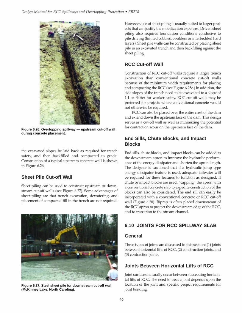
However, use of sheet piling is usually suited to larger proj-ects that can justify the mobilization expenses. Driven sheetpiling also requires foundation conditions conducive topile driving (limited cobbles, boulders or interbedded hardlayers). Sheet pile walls can be constructed by placing sheetpile in an excavated trench and then backfilling against thesheet piling.
RCC Cut-off Wall
Construction of RCC cut-off walls require a larger trenchexcavation than conventional concrete cut-off wallsbecause of the minimum width requirements for placingand compacting the RCC (see Figure 6.25c.) In addition, theside slopes of the trench need to be excavated to a slope of1:1 or flatter for worker safety. RCC cut-off walls may bepreferred for projects where conventional concrete wouldnot otherwise be required.
RCC can also be placed over the entire crest of the damand extend down the upstream face of the dam. This designserves as a cut-off wall as well as minimizing the potentialfor contraction scour on the upstream face of the dam.
End Sills, Chute Blocks, and ImpactBlocks
End sills, chute blocks, and impact blocks can be added tothe downstream apron to improve the hydraulic perform-ance of the energy dissipater and shorten the apron length.The designer is cautioned that if a hydraulic jump typeenergy dissipator feature is used, adequate tailwater willbe required for these features to function as designed. Ifchute or impact blocks are used, “capping” the apron witha conventional concrete slab to expedite construction of theblocks can also be considered. The end sill can easily beincorporated with a conventional concrete or RCC cut-offwall (Figure 6.28). Riprap is often placed downstream ofthe RCC apron to protect the downstream edge of the RCC,and to transition to the stream channel.
6.10 JOINTS FOR RCC SPILLWAY SLAB
General
Three types of joints are discussed in this section: (1) jointsbetween horizontal lifts of RCC, (2) construction joints, and(3) contraction joints.
Joints Between Horizontal Lifts of RCC
Joint surfaces naturally occur between succeeding horizon-tal lifts of RCC. The need to treat a joint depends upon thelocation of the joint and specific project requirements forjoint bonding.
40
Design Manual for RCC Spillways and Overtopping Protection • EB218
the excavated slopes be laid back as required for trenchsafety, and then backfilled and compacted to grade.Construction of a typical upstream concrete wall is shownin Figure 6.26.
Sheet Pile Cut-off Wall
Sheet piling can be used to construct upstream or down-stream cut-off walls (see Figure 6.27). Some advantages ofsheet piling are that trench excavation, dewatering, andplacement of compacted fill in the trench are not required.
Figure 6.26. Overtopping spillway — upstream cut-off wallduring concrete placement.
Figure 6.27. Steel sheet pile for downstream cut-off wall(McKinney Lake, North Carolina).
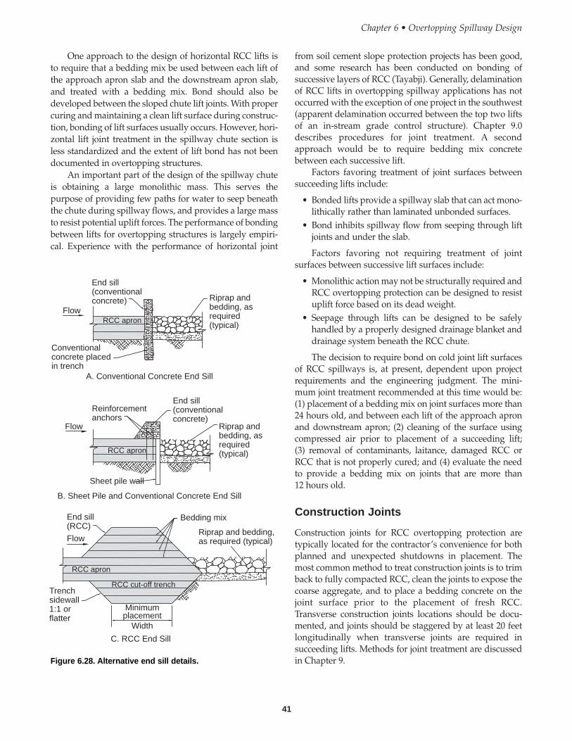
41
One approach to the design of horizontal RCC lifts isto require that a bedding mix be used between each lift ofthe approach apron slab and the downstream apron slab,and treated with a bedding mix. Bond should also bedeveloped between the sloped chute lift joints. With propercuring and maintaining a clean lift surface during construc-tion, bonding of lift surfaces usually occurs. However, hori-zontal lift joint treatment in the spillway chute section isless standardized and the extent of lift bond has not beendocumented in overtopping structures.
An important part of the design of the spillway chuteis obtaining a large monolithic mass. This serves thepurpose of providing few paths for water to seep beneaththe chute during spillway flows, and provides a large massto resist potential uplift forces. The performance of bondingbetween lifts for overtopping structures is largely empiri-cal. Experience with the performance of horizontal joint
from soil cement slope protection projects has been good,and some research has been conducted on bonding ofsuccessive layers of RCC (Tayabji). Generally, delaminationof RCC lifts in overtopping spillway applications has notoccurred with the exception of one project in the southwest(apparent delamination occurred between the top two liftsof an in-stream grade control structure). Chapter 9.0describes procedures for joint treatment. A secondapproach would be to require bedding mix concretebetween each successive lift.
Factors favoring treatment of joint surfaces betweensucceeding lifts include:
• Bonded lifts provide a spillway slab that can act mono-lithically rather than laminated unbonded surfaces.
• Bond inhibits spillway flow from seeping through liftjoints and under the slab.
Factors favoring not requiring treatment of jointsurfaces between successive lift surfaces include:
• Monolithic action may not be structurally required andRCC overtopping protection can be designed to resistuplift force based on its dead weight.
• Seepage through lifts can be designed to be safelyhandled by a properly designed drainage blanket anddrainage system beneath the RCC chute.
The decision to require bond on cold joint lift surfacesof RCC spillways is, at present, dependent upon projectrequirements and the engineering judgment. The mini-mum joint treatment recommended at this time would be:(1) placement of a bedding mix on joint surfaces more than24 hours old, and between each lift of the approach apronand downstream apron; (2) cleaning of the surface usingcompressed air prior to placement of a succeeding lift;(3) removal of contaminants, laitance, damaged RCC orRCC that is not properly cured; and (4) evaluate the needto provide a bedding mix on joints that are more than12 hours old.
Construction Joints
Construction joints for RCC overtopping protection aretypically located for the contractor’s convenience for bothplanned and unexpected shutdowns in placement. Themost common method to treat construction joints is to trimback to fully compacted RCC, clean the joints to expose thecoarse aggregate, and to place a bedding concrete on thejoint surface prior to the placement of fresh RCC.Transverse construction joints locations should be docu-mented, and joints should be staggered by at least 20 feetlongitudinally when transverse joints are required insucceeding lifts. Methods for joint treatment are discussedin Chapter 9.
Chapter 6 • Overtopping Spillway Design
Flow
Flow
Flow
End sill(conventionalconcrete)
End sill(conventionalconcrete)
Riprap andbedding, asrequired(typical)
Riprap andbedding, asrequired(typical)
Conventionalconcrete placedin trench
RCC apron
RCC apron
RCC apron
RCC cut-off trench
Reinforcementanchors
Sheet pile wall
End sill(RCC)
Bedding mix
Riprap and bedding,as required (typical)
Trenchsidewall1:1 orflatter
Minimumplacement
Width
A. Conventional Concrete End Sill
B. Sheet Pile and Conventional Concrete End Sill
C. RCC End Sill
Figure 6.28. Alternative end sill details.
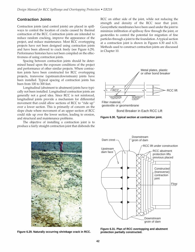
42
Design Manual for RCC Spillways and Overtopping Protection • EB218
RCC on either side of the joint, while not reducing thestrength and density of the RCC near that joint.Geosynthetic membranes have been used under the joint tominimize infiltration of spillway flow through the joint, orgeotextiles to control the potential for migration of fineparticles through a joint to the foundation. A typical sectionat a contraction joint is shown in Figures 6.30 and 6.31.Methods used to construct contraction joints are discussedin Chapter 10.
Contraction Joints
Contraction joints (and control joints) are placed in spill-ways to control the location of cracks caused by thermalcontraction of the RCC. Contraction joints are intended toreduce random cracking, improve the appearance of theproject, and reduce maintenance. Most RCC overtoppingprojects have not been designed using contraction jointsand have been allowed to crack freely (see Figure 6.29).Performance histories have not been compiled on the effec-tiveness of using contraction joints.
Spacing between contraction joints should be deter-mined based upon the exposure conditions of the projectand performance of other similar projects. Where contrac-tion joints have been constructed for RCC overtoppingprojects, transverse (upstream:downstream) joints havebeen installed. Typical spacing of contraction joints hasbeen from 100 to 300 feet.
Longitudinal (abutment to abutment) joints have typi-cally not been installed. Longitudinal contraction joints aregenerally not a good idea. Since RCC is not reinforced,longitudinal joints provide a mechanism for differentialmovement that could allow sections of RCC to “ride up”over a lower section. This is primarily of concern on theslope chute where movement of an upper section of RCCcould ride up over the lower section, leading to erosion,and structural and maintenance problems.
The objective of installing a contraction joint is toproduce a fairly straight contraction joint that disbonds the
Figure 6.29. Naturally occurring shrinkage crack in RCC.
Metal plates, plasticor other bond breaker
RCC liftRCC
Filter material,geotextile or geomembrane
Bond Breaker in Each RCC Lift
Figure 6.30. Typical section at contraction joint.
Dam crest
Upstreamdam face
Downstreamgroin of dam
RCC lift under construction
RCC abutmentprotection liftsprevious placed
Constructed(transverse)contractionjoint
Flow
Downstreamgroin of dam
Figure 6.31. Plan of RCC overtopping and abutmentprotection partially constructed.
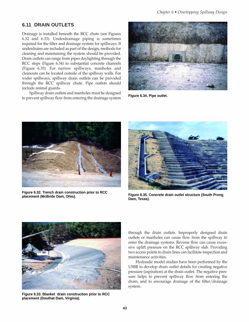
43
6.11 DRAIN OUTLETS
Drainage is installed beneath the RCC chute (see Figures6.32 and 6.33). Underdrainage piping is sometimesrequired for the filter and drainage system for spillways. Ifunderdrains are included as part of the design, methods forcleaning and maintaining the system should be provided.Drain outlets can range from pipes daylighting through theRCC steps (Figure 6.34) to substantial concrete channels(Figure 6.35). For narrow spillways, manholes andcleanouts can be located outside of the spillway walls. Forwider spillways, spillway drain outlets can be providedthrough the RCC spillway chute. Pipe outlets shouldinclude animal guards.
Spillway drain outlets and manholes must be designedto prevent spillway flow from entering the drainage system
through the drain outlets. Improperly designed drainoutlets or manholes can cause flow from the spillway toenter the drainage systems. Reverse flow can cause exces-sive uplift pressure on the RCC spillway slab. Providingtwo access points to drain lines can facilitate inspection andmaintenance activities.
Hydraulic model studies have been performed by theUSBR to develop drain outlet details for creating negativepressure (aspiration) at the drain outlet. The negative pres-sure helps to prevent spillway flow from entering thedrain, and to encourage drainage of the filter/drainagesystem.
Chapter 6 • Overtopping Spillway Design
Figure 6.32. Trench drain construction prior to RCCplacement (McBride Dam, Ohio).
Figure 6.33. Blanket drain construction prior to RCCplacement (Douthat Dam, Virginia).
Figure 6.34. Pipe outlet.
Figure 6.35. Concrete drain outlet structure (South ProngDam, Texas).

44
Design Manual for RCC Spillways and Overtopping Protection • EB218
Abutment Protection
Abutment protection is required for all overtoppingdesigns (Figure 6.1). The abutment protection should bedesigned to safely contain the spillway flow within theembankment groins, and transition to the stream channel.The abutment protection should be keyed into rock foun-dation, when possible, to prevent undermining the RCCslab if water overflows the abutment protection. Designswhich direct flow in a converging configuration (such ascovering the entire downstream face as shown in Figure6.1b), result in three-dimensional concentrated flow chan-nels (which increases the velocity and flow concentrationfrom top to bottom) at the abutment groins. Designersshould be aware of complicated hydraulic conditions thatcould exist at the abutment groins and the erosion potentialof the foundation. The potential could lead to dam failure.
The hydraulic analysis of flow depth and velocity forthe overtopping spillway design, should provide a designthat protects the abutments from erosion and safely conveythe flow away from the dam. Abutment protection can be
6.12 TRAINING WALLS AND ABUTMENTPROTECTION
General
Spillway flow training walls contain spillway flow withinthe RCC chute and protect the dam and abutments frompotential erosion. Overtopping of the spillway walls or theabutment protection can result in erosion of the damembankment. This is of particular concern because highvelocity concentrated flow can occur along the critical abut-ment areas of the dam where the walls are typicallylocated. Examples of various types of training walls andabutment protection that have been used are shown inFigures 6.36, 6.37, 6.38, and 6.39.
Figure 6.36. RCC training wall constructed using verticalforms (Salado No. 10, Texas).
Figure 6.37. RCC training walls constructed using formedsloping RCC wall (Anthem No. 2, Nevada).
Figure 6.38. RCC training wall (Kyle Canyon Dam, Nevada).
Figure 6.39. RCC training wall in background (Black RockDam, New Mexico).
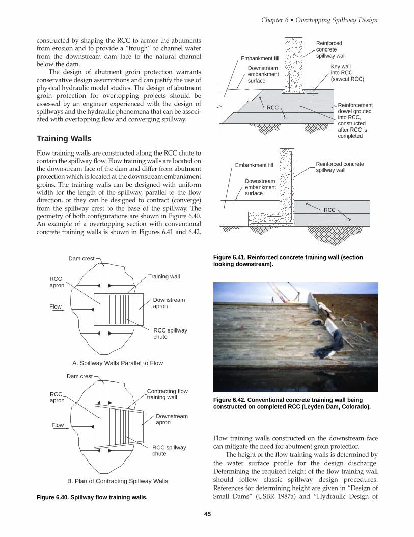
45
constructed by shaping the RCC to armor the abutmentsfrom erosion and to provide a “trough” to channel waterfrom the downstream dam face to the natural channelbelow the dam.
The design of abutment groin protection warrantsconservative design assumptions and can justify the use ofphysical hydraulic model studies. The design of abutmentgroin protection for overtopping projects should beassessed by an engineer experienced with the design ofspillways and the hydraulic phenomena that can be associ-ated with overtopping flow and converging spillway.
Training Walls
Flow training walls are constructed along the RCC chute tocontain the spillway flow. Flow training walls are located onthe downstream face of the dam and differ from abutmentprotection which is located at the downstream embankmentgroins. The training walls can be designed with uniformwidth for the length of the spillway, parallel to the flowdirection, or they can be designed to contract (converge)from the spillway crest to the base of the spillway. Thegeometry of both configurations are shown in Figure 6.40.An example of a overtopping section with conventionalconcrete training walls is shown in Figures 6.41 and 6.42.
Flow training walls constructed on the downstream facecan mitigate the need for abutment groin protection.
The height of the flow training walls is determined bythe water surface profile for the design discharge.Determining the required height of the flow training wallshould follow classic spillway design procedures.References for determining height are given in “Design ofSmall Dams” (USBR 1987a) and “Hydraulic Design of
Chapter 6 • Overtopping Spillway Design
Flow
RCCapron
Dam crest
Training wall
Downstreamapron
RCC spillwaychute
Dam crest
RCCapron
Flow
Contracting flowtraining wall
Downstreamapron
RCC spillwaychute
A. Spillway Walls Parallel to Flow
B. Plan of Contracting Spillway Walls
Figure 6.40. Spillway flow training walls.
Embankment fill
Downstreamembankmentsurface
Reinforcedconcretespillway wall
Key wallinto RCC(sawcut RCC)
Reinforcementdowel groutedinto RCC,constructedafter RCC iscompleted
RCC
Embankment fill
Downstreamembankmentsurface
Reinforced concretespillway wall
RCC
Figure 6.41. Reinforced concrete training wall (sectionlooking downstream).
Figure 6.42. Conventional concrete training wall beingconstructed on completed RCC (Leyden Dam, Colorado).
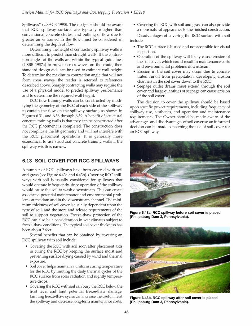
Spillways” (USACE 1990). The designer should be awarethat RCC spillway surfaces are typically rougher thanconventional concrete chutes, and bulking of flow due togreater air entrained in the flow must be considered indetermining the depth of flow.
Determining the height of contracting spillway walls ismore difficult to predict than straight walls. If the contrac-tion angles of the walls are within the typical guidelines(USBR 1987a) to prevent cross waves on the chute, thenstandard design aids can be used to estimate wall height.To determine the maximum contraction angle that will notform cross waves, the reader is referred to referencesdescribed above. Sharply contracting walls may require theuse of a physical model to predict spillway performanceand to determine the required wall height.
RCC flow training walls can be constructed by modi-fying the geometry of the RCC at each side of the spillwayto contain the flow on the spillway surface, as shown inFigures 6.31, and 6.36 through 6.39. A benefit of structuralconcrete training walls is that they can be constructed afterthe RCC placement is completed. The construction doesnot complicate the lift geometry and will not interfere withthe RCC placement operations. It is generally moreeconomical to use structural concrete training walls if thespillway width is narrow.
6.13 SOIL COVER FOR RCC SPILLWAYS
A number of RCC spillways have been covered with soiland grass (see Figure 6.43a and 6.43b). Covering RCC spill-ways with soil is usually considered for spillways thatwould operate infrequently, since operation of the spillwaywould cause the soil to wash downstream. This can createassociated potential maintenance and environmental prob-lems at the dam and in the downstream channel. The mini-mum thickness of soil cover is usually dependent upon thetype of soil, and the store and release requirements of thesoil to support vegetation. Freeze-thaw protection of theRCC can also be a consideration in wet climates subject tofreeze-thaw conditions. The typical soil cover thickness hasbeen about 2 feet.
Several benefits that can be obtained by covering anRCC spillway with soil include:
• Covering the RCC with soil soon after placement aidsin curing the RCC by keeping the surface moist andpreventing surface drying caused by wind and thermalexposure.
• Soil cover helps maintain a uniform curing temperaturefor the RCC by limiting the daily thermal cycles of theRCC surface from solar radiation and nightly tempera-ture drops.
• Covering the RCC with soil can bury the RCC below thefrost level and limit potential freeze-thaw damage.Limiting freeze-thaw cycles can increase the useful life atthe spillway and decrease long-term maintenance costs.
46
Design Manual for RCC Spillways and Overtopping Protection • EB218
• Covering the RCC with soil and grass can also providea more natural appearance to the finished construction.Disadvantages of covering the RCC surface with soil
include:• The RCC surface is buried and not accessible for visual
inspection.• Operation of the spillway will likely cause erosion of
the soil cover, which could result in maintenance costsand environmental problems downstream.
• Erosion in the soil cover may occur due to concen-trated runoff from precipitation, developing erosionchannels in the soil cover down to the RCC.
• Seepage outlet drains must extend through the soilcover and large quantities of seepage can cause erosionof the soil cover.The decision to cover the spillway should be based
upon specific project requirements, including frequency ofspillway use, aesthetics, and operation and maintenancerequirements. The Owner should be made aware of theadvantages and disadvantages of soil cover so an informeddecision can be made concerning the use of soil cover foran RCC spillway.
Figure 6.43a. RCC spillway before soil cover is placed(Philipsburg Dam 3, Pennsylvania).
Figure 6.43b. RCC spillway after soil cover is placed(Philipsburg Dam 3, Pennsylvania).

CHAPTER 7
RCC Mix Design
7.1 GENERAL
The purpose of an RCC mix design is to develop project-specific properties to meet the structure design require-ments, and to provide a basis for developing the projectbidding documents. Perhaps the two most widely usedproperties in developing criteria for RCC mixes are thecompressive strength of the RCC mixture and the worka-bility (compactability) of a mix. The compressive stresses inan RCC overtopping spillway structure are typically low.However, compressive strength is generally specified as anindirect indicator of the durability of the RCC mix. Theworkability of a mix (such as slump in conventionalconcrete) is also important in obtaining the desired in-placeproperties. A uniform measure of workability of RCC,which by definition is a no-slump concrete, has not yetbeen established. But there is sufficient information toprovide the necessary guidance for RCC applications. Wehave also seen a third property that should be consideredin developing RCC mixes — uniformity. Mix designs, andmore importantly developing criteria for specifying mixdesigns, are discussed below.
RCC by its very nature has some characteristics of soiland some characteristics of concrete. And the nature of theRCC changes throughout the process. For example, anRCC mix is specified to provide the properties of concrete.Before curing, the RCC is placed and compacted like agranular soil with only frictional strength. After curing,the RCC is a cemented product that has both frictional andcohesive strength. This has a significant effect on all stagesof design, construction, and quality control for RCC.Throughout this process the long established properties ofsoil mechanics and concrete technology intermingle. It isimportant that the user develop an understanding of both,so that the most appropriate discipline can be used toguide the application of RCC throughout the variousstages of a project.
Perhaps one of the most diverse aspects of RCC is inthe area of mix designs. Since the primary property that is
used in RCC design is compressive strength, it is only natu-ral that proportioning be performed using traditionalconcrete mix proportioning procedures. However, sinceRCC is spread and compacted with earthmoving equip-ment (dozers, surface compactors, etc.), conventionalconcrete proportioning methods which were designed formaterial that is consolidated using internal immersionvibrators, have not been correlated with the compactionequipment used in traditional earthwork. In contrast, fillcontrol for earthwork placement is generally performedusing a compaction test (such as ASTM D 1557). A goodcorrelation has been developed between compaction testproperties and surface compactors.
The compaction test establishes the workability (com-pactability) of the material over a range of moisturecontents, and is correlated to achieving the maximum drydensity using surface vibratory compactors. However,granular fill placed to the maximum dry density at the opti-mum moisture content will contain more air voids thanconventional concrete and consequently can have a higherpermeability, and lower durability and compressivestrength, relatively, than conventional concrete. The airvoids content of a compacted granular fill can be reducedby placing the granular fill at a moisture content aboveoptimum, during which air is further driven out of themixture as compaction occurs.
The experience of practitioners from the geotechnicaland concrete disciplines has given rise to two generalapproaches to mix designs for RCC. Mix designs can beperformed using a modified Proctor compaction test(ASTM D 1557) process or conventional concrete mixproportioning method. Both are suitable for developingRCC mix proportions, but use different indicators forworkability. With experience in RCC construction, a similarmixture can be developed by either method, and mixeshave been found to be similar when the moisture content ofthe RCC is about 1 percent above optimum moisturecontent (ASTM D 1557).
47
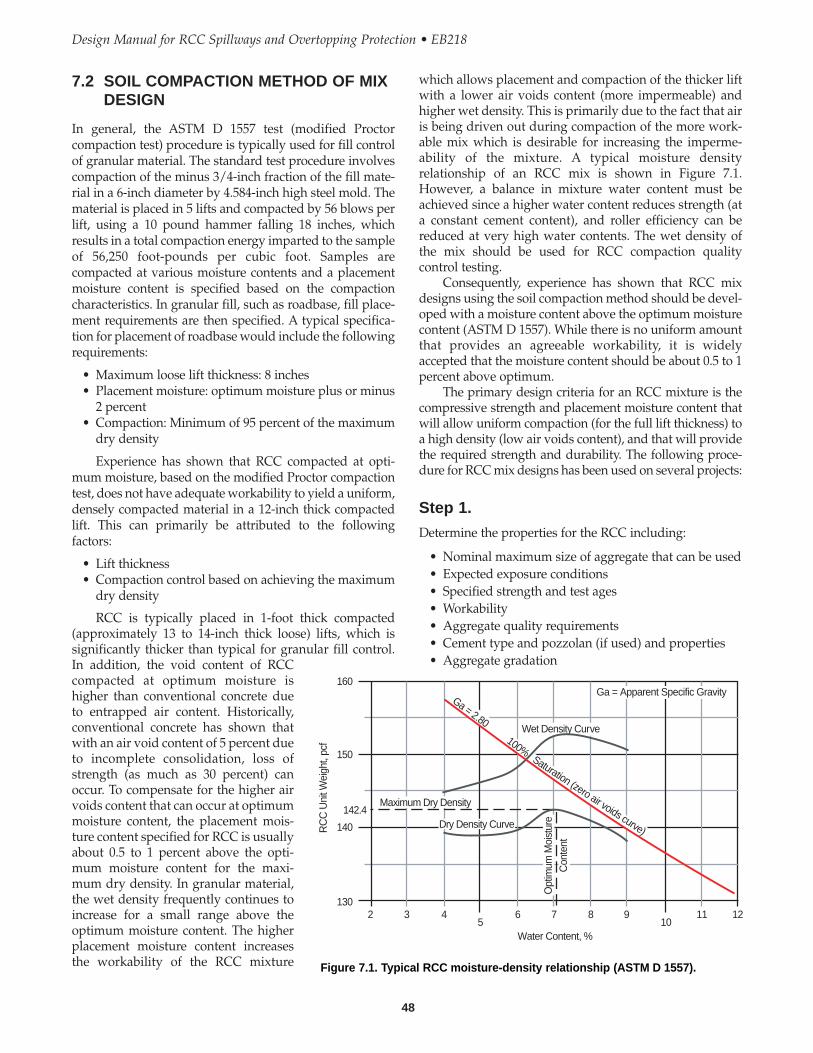
which allows placement and compaction of the thicker liftwith a lower air voids content (more impermeable) andhigher wet density. This is primarily due to the fact that airis being driven out during compaction of the more work-able mix which is desirable for increasing the imperme-ability of the mixture. A typical moisture densityrelationship of an RCC mix is shown in Figure 7.1.However, a balance in mixture water content must beachieved since a higher water content reduces strength (ata constant cement content), and roller efficiency can bereduced at very high water contents. The wet density ofthe mix should be used for RCC compaction qualitycontrol testing.
Consequently, experience has shown that RCC mixdesigns using the soil compaction method should be devel-oped with a moisture content above the optimum moisturecontent (ASTM D 1557). While there is no uniform amountthat provides an agreeable workability, it is widelyaccepted that the moisture content should be about 0.5 to 1percent above optimum.
The primary design criteria for an RCC mixture is thecompressive strength and placement moisture content thatwill allow uniform compaction (for the full lift thickness) toa high density (low air voids content), and that will providethe required strength and durability. The following proce-dure for RCC mix designs has been used on several projects:
Step 1.
Determine the properties for the RCC including:
• Nominal maximum size of aggregate that can be used• Expected exposure conditions• Specified strength and test ages• Workability• Aggregate quality requirements• Cement type and pozzolan (if used) and properties• Aggregate gradation
7.2 SOIL COMPACTION METHOD OF MIXDESIGN
In general, the ASTM D 1557 test (modified Proctorcompaction test) procedure is typically used for fill controlof granular material. The standard test procedure involvescompaction of the minus 3/4-inch fraction of the fill mate-rial in a 6-inch diameter by 4.584-inch high steel mold. Thematerial is placed in 5 lifts and compacted by 56 blows perlift, using a 10 pound hammer falling 18 inches, whichresults in a total compaction energy imparted to the sampleof 56,250 foot-pounds per cubic foot. Samples arecompacted at various moisture contents and a placementmoisture content is specified based on the compactioncharacteristics. In granular fill, such as roadbase, fill place-ment requirements are then specified. A typical specifica-tion for placement of roadbase would include the followingrequirements:
• Maximum loose lift thickness: 8 inches• Placement moisture: optimum moisture plus or minus
2 percent• Compaction: Minimum of 95 percent of the maximum
dry density
Experience has shown that RCC compacted at opti-mum moisture, based on the modified Proctor compactiontest, does not have adequate workability to yield a uniform,densely compacted material in a 12-inch thick compactedlift. This can primarily be attributed to the followingfactors:
• Lift thickness• Compaction control based on achieving the maximum
dry density
RCC is typically placed in 1-foot thick compacted(approximately 13 to 14-inch thick loose) lifts, which issignificantly thicker than typical for granular fill control.In addition, the void content of RCCcompacted at optimum moisture ishigher than conventional concrete dueto entrapped air content. Historically,conventional concrete has shown thatwith an air void content of 5 percent dueto incomplete consolidation, loss ofstrength (as much as 30 percent) canoccur. To compensate for the higher airvoids content that can occur at optimummoisture content, the placement mois-ture content specified for RCC is usuallyabout 0.5 to 1 percent above the opti-mum moisture content for the maxi-mum dry density. In granular material,the wet density frequently continues toincrease for a small range above theoptimum moisture content. The higherplacement moisture content increasesthe workability of the RCC mixture
48
Design Manual for RCC Spillways and Overtopping Protection • EB218
160
150
140
142.4
1302 3 4 6 7 8 9 11 12
5 10Water Content, %
RC
C U
nit W
eigh
t, pc
f
Ga = 2.80
100%Saturation (zero air voids curve)
Wet Density Curve
Ga = Apparent Specific Gravity
Dry Density Curve
Maximum Dry Density
Opt
imum
Moi
stur
eC
onte
nt
Figure 7.1. Typical RCC moisture-density relationship (ASTM D 1557).
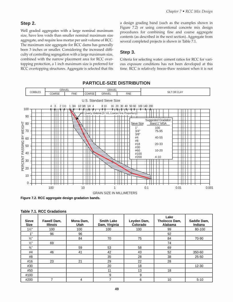
49
Step 2.
Well graded aggregates with a large nominal maximumsize, have less voids than smaller nominal maximum sizeaggregate, and require less mortar per unit volume of RCC.The maximum size aggregate for RCC dams has generallybeen 3 inches or smaller. Considering the increased diffi-culty of controlling segregation with a large maximum size,combined with the narrow placement area for RCC over-topping protection, a 1 inch maximum size is preferred forRCC overtopping structures. Aggregate is selected that fits
a design grading band (such as the examples shown inFigure 7.2) or using conventional concrete mix designprocedures for combining fine and coarse aggregatecontents (as described in the next section). Aggregate fromseveral completed projects is shown in Table 7.1.
Step 3.
Criteria for selecting water: cement ratios for RCC for vari-ous exposure conditions has not been developed at thistime. RCC is relatively freeze-thaw resistant when it is not
Chapter 7 • RCC Mix Design
GRAVEL GRAVELGRAVEL FINEFINE COARSECOARSECOBBLES SILT OR CLAY
100 10 1 0.1 0.01 0.001
100
90
80
70
60
50
40
30
20
10
0
PE
RC
EN
T P
AS
SIN
G B
Y W
EIG
HT
GRAIN SIZE IN MILLIMETERS
4 3 2 11/2 1 3/4 1/2 3/8 1/4 4 8 10 16 20 30 40 50 60 100 140 200
Quarry Material (57:43, Coarse:Fine Proportion)
1"3/4"3/8"#4#8#18#30#60#100#200
10075-95
40-55
20-33
10-20
4-10
Sieve Size Band 1" MSASuggested Gradation
U.S. Standard Sieve Size
PARTICLE-SIZE DISTRIBUTION
Figure 7.2. RCC aggregate design gradation bands.
Table 7.1. RCC GradationsLake
Sieve Fawell Dam, Mona Dam, Smith Lake Leyden Dam, Tholocco Dam, Saddle Dam,Size Illinois Utah Dam, Virginia Colorado Alabama Indiana11⁄2" 100 100 100 100 99 80-100
1" 96 96 923⁄4" 84 70 75 84 70-901⁄2" 69 743⁄8" 59 53 58 69#4 46 41 42 43 52 350-60#8 35 28 38 25-50
#16 23 21 29 22 28#30 20 18 12-30#50 11 13 18
#100 9 9#200 7 4 7 6 10 5-10
weight (or the water content at the maximum wet unitweight), is then selected for the RCC mix design.
Step 6.
Prepare cylinders for compressive strength testing usingASTM C 1435, and other testing deemed appropriate, forthe mid-range cement content for compression testing overthe range of design age with two or three cylinders for eachage to be tested.
Step 7.
Calculate mix proportions for RCC at the design watercontent from the compaction curve, or, determine the unitweight of the RCC cylinders, and calculate the entrappedair content or measure in accordance with ASTM C 138 orC 231. The entrapped air content should range between 1and 2 percent. If the entrapped air content is higher thanabout 3 percent, uniform compaction of the RCC full depthwill likely be difficult. A higher air void content will resultin a more pervious, lower durability, and potentially lowerstrength RCC. Adjust the water content, if needed, toprovide a more workable RCC mix. Prepare a series ofcylinders at different cement contents using ASTM C 1435.Vary the cement content by increments of 10 to 15 percent,above and below the mid-range cement content.
Step 8.
Prepare a semi-log plot of compressive strength versus agefor each cement content (or water to cement ratio). Thecement content to attain the design compressive strengthcan be selected from the curves. When selecting a cementcontent, consideration should be given to the variability ofthe compressive strength of RCC which is usually higherthan conventional concrete.
Step 9.
Additional cylinders can also be prepared at differentwater contents to evaluate the effect of water content on thestrength of each mix. The final determination of the watercontent will usually be decided in the field based on a testfill placement to evaluate the workability of the mix withthe project specific materials and equipment.
Step 10.
Mix proportions that can be used by the plant operator areprepared for the specifications. Mix proportions (by weightand volume) that result in a unit volume measured byabsolute volume should be provided for each constituent.Mixing plants are set up in various methods to proportionthe various constituents. These range from proportioningmaterial based on: (1) the weight of each constituent,expressed as a percentage of the total dry weight of mate-
critically saturated, even in severe climates, but may besusceptible to freeze-thaw damage when critically satu-rated. Efforts to entrain air in RCC has to date met withdebatable success. In particular, air entrained RCC in fieldproduction has not been consistently produced. The currentpractice for design of RCC for overtopping protection is tospecify a minimum compressive strength of 3,000 psi, and amaximum water: cementitious ratio of less than 0.9. Thestructures are also generally designed to be maintained in adry condition (not critically saturated). If the RCC is to beexposed to water continuously, or has the potential tobecome critically saturated, the designer should considerthe use of conventional air-entrained concrete in areas ofmoderate to severe exposure conditions. Some designsspecify the use of a minimum compressive strength of 4,000psi for severe service conditions.
An RCC mix for laboratory testing will be designed ata mid-range cement content. As an initial trial, a mid-rangecement content would be about 1 pound of cement per yd3
for each 7.5 psi of design compressive strength (i.e., for adesign compressive strength of 3,000 psi at 28 days, use 400pounds per yd3 of cement).
Step 4.
Develop the modified Proctor compaction curve (ASTMD 1557) using the RCC mix at the mid-range cementcontent. If the aggregate contains material greater than3⁄4-inch, the ASTM D 1557 procedures should be adjusted asdescribed by Wong, Bischoff, and Johnson (1988) andArnold (1992). Experience with RCC has shown that theoven dry water content RCC of samples from thecompaction test can be erratic; therefore, the calculatedwater content should also be considered for constructingthe compaction curve based on controlled tests of theoreti-cal water content versus oven dry (ASTM D 2216). Onesuccessful method of controlling the design water contentof the compaction samples is to pre-measure material foreach sample point, add the required water to eachcompaction sample at about 1 percent increments, andallow the samples to “season” for 24 hours in sealedcontainers without cement. The cement is then manuallymixed in to each sample immediately prior to compactingthe sample. The moisture content can also be measured, forinformation purposes, using the entire compaction sample.Comparison of “hot plate” drying versus controlled theo-retical moisture contents have also shown a more reason-able comparison with the theoretical moisture content thanthe conventional ASTM D 2216 test.
A compaction curve is drawn of the dry unit weightversus calculated water content, and wet unit weightversus calculated water content, as shown in Figure 7.1.
Step 5.
A design water content of about 0.5 percent above opti-mum water content, based on the maximum dry unit
50
Design Manual for RCC Spillways and Overtopping Protection • EB218
rial (i.e., weight of dry aggregate plus cement plus fly ash);(2) the weight of each constituent in a saturated surface drycondition (i.e., weight of aggregate in a saturated surfacedry condition plus cement plus fly ash); and (3) the weightof each constituent in the dry condition and the total watercontent (i.e., weight of dry aggregate plus cement plus flyash plus total water content [absorbed water plus excesswater above the saturated surface dry condition]). It is crit-ical that the engineer understands how the plant operate sothat the design mix proportions can be correctly conveyedto the contractor. At a minimum, constituents to beprovided are:
• Cement type, and pozzolan (if used), content• Aggregate content (SSD) (coarse and fine)• Water content (above SSD)• Total water content• Specific gravity (SSD)• Absorption• Air content• Water:Cement + Fly ash Ratio
Step 11.
Field adjustments will be required to account for the equip-ment type and environmental conditions for full scaleproduction. Initial field adjustments are typically made in atest section separate from the structure. Test sectionconstruction should include evaluation of the in-place wetdensity throughout the lift thickness, and the entrapped aircontent versus the mix design properties. Adjustments willalso be required during production placement.
Mix design calculations for an Example Project areshown in Appendix A.
7.3 CONVENTIONAL CONCRETEMETHOD OF MIX DESIGN
Conventional concrete mix proportioning looks at achiev-ing a gradation that can be densely consolidated withinternal vibrators. Workability for conventional concrete isusually measured by a slump test (ASTM C 143). However,the slump test is not a suitable method for indicating work-ability (compactability) of “no slump” RCC using surfacecompactors. A test procedure was previously developedfor testing of no-slump concrete. The test for no-slumpconcrete uses a vibratory table to consolidate a sample withan external load placed on top. The test (ASTM C 1170) iscommonly referred to as the Vebe test.
Mixture proportioning using the conventionalconcrete procedures for no-slump concrete, and using theVebe test for workability assessment, is detailed in refer-ences such as “USACE Engineering Manual EM 1110–2-2006” and “American Concrete Institute (ACI) 211.1,Mixture Proportioning.” Proportioning methods includeboth weight and absolute volume methods. The absolute
volume method is more accurate and is the methodsummarized below.
RCC is designed with a consistency that is sufficientlystiff to support vibrating rollers. A key to the design of RCCmixtures using conventional concrete proportioning proce-dures is providing sufficient paste to fill all the voidsbetween aggregate particles and to allow consolidationunder externally applied vibration. The following proce-dure for RCC mix designs has been used on several projects:
Step 1.
Determine the properties for the RCC including:
• Nominal maximum size of aggregate that can be used• Expected exposure conditions• Specified strength and test ages• Workability (Vebe time)• Aggregate quality requirements• Cement type and pozzolan (if used) and properties• Aggregate gradation
Step 2.
Aggregate selection – There is a tendency for aggregatelarger than 11⁄2 inches to segregate when deposited in smallareas such as the narrow “lanes” that are typical of overtop-ping spillway construction. Therefore, a maximum aggre-gate size of 1 inch is recommended for the RCC overtoppingsection design. Compare gradings of combined coarse andfine aggregate with other gradings such as Tables 3.1 and 3.2(USACE EM 1110-2-2006) (see Appendix A).
The maximum fines content will vary depending onthe type of material. The use of crusher fines, rock flour,and non-plastic fines can serve as a mineral filler in an RCCmix. Fines with a plasticity index (PI) greater than 4 shouldonly be considered after appropriate laboratory testing.
Step 3.
Estimate the water requirements using Table 3.3 (EM 1110-2-2006) (see Appendix A) and select the required cementcontent from Figure 3.2 (EM 1110-2-2006) (see Appendix A)for the design strength requirement.
Step 4.
Calculate the absolute volume of cement and water andassume an entrapped air content (typically 1 to 2 percent).
Step 5.
Calculate the absolute volume of total aggregate by sub-tracting the absolute volume of each material from the unitvolume.
Determine the sand content of the total volume ofaggregate from Table 3.3 (EM 1110–2-2006).
51
Chapter 7 • RCC Mix Design
Step 10.Determine the unit weight of the RCC cylinders and calcu-late the entrapped air content, or measure in accordancewith ASTM C 138 or C 231, and compare with the TAF unitweight. Since RCC cannot be consolidated by rodding, thesample should be consolidated in the air meter containerusing the Vebe table (ASTM C 1176) or by an electrichammer (ASTM C 1435). The entrapped air content shouldrange between 1 and 2 percent.
Step 11.Prepare a semi-log plot of compressive strength versus agefor each water cement ratio. The cement content to attainthe design compressive strength can be interpolated fromthe curves. When selecting a cement content, considerationshould be given to the variability of the compressivestrength of RCC which is usually higher than conventionalconcrete.
Step 12.Additional cylinders can also be prepared at differentwater contents to evaluate the effect of water content on thestrength of each mix. The final determination of the watercontent will usually be decided in the field based on a testfill placement to evaluate the workability of the mix withthe project-specific materials and equipment.
Step 13.Mix proportions that can be used by the plant operator areprepared for the specifications. Mix proportions (by weightand volume) that result in a unit volume measured byabsolute volume should be provided for each constituent.At a minimum, constituents to be provided are:
• Cement type, and pozzolan (if used), content• Aggregate content (SSD) (coarse and fine)• Water content (above SSD)• Total water content• Specific gravity (SSD)• Absorption• Air content• Water:Cement + Fly ash ratio
Step 14.Field adjustments will be required to account for theequipment type and environmental conditions for full scaleproduction. Initial field adjustments are typically made in atest section separate from the structure. Test sectionconstruction should include evaluation of the in-place wetdensity throughout the lift thickness, and the entrapped aircontent versus the mix design properties. Adjustments willbe required during production placement.
Mix design calculations for an example project areshown in Appendix A.
Determine the absolute volume of the coarse aggregateby subtracting the volume of sand from the total volume ofaggregate.
Step 6.
Calculate the volume of paste and mortar, and the ratio ofthe volume of paste to the volume of mortar, from theabsolute volumes computed above. The mortar volumeincludes the aggregate finer than the No. 4 sieve, cementi-tious material, water, and entrapped air. The paste volumeincludes the volume of aggregate finer than the No. 200sieve, cementitious material, water, and entrapped air(USACE EM 1110-2-2006, Table 3.3) (see Appendix A). Theminimum volume of paste/volume of mortar ratio shouldbe about 0.42 to ensure that all voids are filled. Adjust thefine aggregate content if required, to increase or decreasethe mortar volume. The quantity of cementitious materialcan be adjusted or the quantity of aggregate finer than theNo. 200 sieve increased to change the paste to mortar ratio.
Step 7.
Convert absolute volume to weight per unit volume foreach constituent in the mixture using the specific gravity ofthe constituent.
Step 8.
Measure out material weights and mix trial batch. RunVebe test in accordance with ASTM C 1170 to evaluateworkability. Adjust water content to modify mixture work-ability to desired Vebe time. RCC mixes with a Vebe time ofless than 20 seconds have a tendency to “pump” signifi-cantly during compaction. This usually is due to a higherwater content and paste content. At the higher watercontent, lower strengths will occur for the same cementcontent. Therefore, a higher cement content will berequired to meet the design strength. For Vebe times inexcess of 45 seconds, some mixes may be too dry foradequate compaction for the full depth of the RCC lift. Thiscan result in higher air voids content with an increasedpermeability, decreased workability, and lower compres-sive strength RCC. A good target Vebe time would bebetween 25 and 35 seconds.
Step 9.
Prepare cylinders for testing using the required cementcontent for compression testing over the range of designage. Prepare a series of cylinders using ASTM C 1176 orC 1435 (two or three cylinders for each age are tested). Varythe cement content by increments of between 10 and 15percent above and below the selected cement content.
52
Design Manual for RCC Spillways and Overtopping Protection • EB218

CHAPTER 8
Instrumentation and Monitoring
The construction of overtopping projects essentially entailsplacing an RCC layer on the downstream slope of an exist-ing embankment dam. It is important to maintain the oper-ation of any existing instrumentation in the embankment.Often, during the rehabilitation of an embankment dam, itis necessary to protect and/or modify the existing instru-mentation systems to allow for the continuation of themonitoring program.
Existing instrumentation systems, such as piezome-ters, inclinometers, and borehole extensometers, are oftenexposed on the downstream slope of the embankment.The designer must make provisions to protect, modify orproperly abandon and replace existing instrumentationsystems.
Additional instrumentation and monitoring systemsthat may be required include:
• Blanket and/or toe drains monitoring.• Permanent survey points to monitor embankment
movement.• Water level gauges or piezometers to monitor the
internal phreatic level and reservoir level.
53

54
Design Manual for RCC Spillways and Overtopping Protection • EB218

CHAPTER 9
Construction Considerations
Construction methods implemented for an RCC overtop-ping project are a hybrid of earthfill and concrete construc-tion techniques. The building of an RCC overtoppingproject involves construction processes that are not typicalfor earthwork or concrete contractors. The speed of earth-fill placement can be realized in RCC construction, but thetiming and the extra level of cleanliness of concreteconstruction is necessary to obtain a quality product inRCC. RCC construction also involves significantly higherplacement rates than typical concrete placement, as well asthe transport method and compaction equipment typicallyused in earthwork. This section discusses constructionissues and conditions that the designer should be aware of(during the design), as well as preparation of constructiondrawings and technical specifications for the successfulcompletion of an RCC overtopping project.
9.1 CONSTRUCTION ACCESS/SITELAYOUT
In design of an RCC overtopping project, site access issuesmust be addressed. Site access, location, and layout willgreatly influence the contractor’s ability to successfullycomplete construction of a project. Some of the issues thatshould be considered in the planning and preparation ofthe construction documents are as follows:
RCC Production Plant Location – The preferred location ofthe RCC production plant is adjacent to or as close as possi-ble to the RCC placement area. Often, because of limitedsite area, or because of the generation of dust and noise inurban areas, an RCC production plant cannot be set up atthe project site. In these instances, the production plantmay be located some distance away from the site. Thedistance to a temporary plant site, or an existing plant,must be relatively close to the project site such that a suffi-cient quantity of material can be delivered, placed, andcompacted within the required time constraints. Typically,the time allowed from the addition of water until finalcompaction of the RCC mix is in the range of 45 to 60
minutes. A travel time of more than 15 minutes for RCCdelivery from off site may be too long to allow adequatetime for placement and compaction of the RCC. Trafficvolumes in urban areas, especially during rush hour, cangreatly impact the travel time to the placement area andmay require adjustment in work hours to avoid trafficcomplications.
When the RCC plant is located on site, the owner mustprovide adequate space for the contractor to set up a plant,and to deliver and store aggregates and cement (and fly ashif used) at the site. This entails locating cement (and fly ash)silos adjacent to the plant and providing sufficient room fortransport trucks to maneuver and off load the materialsand cement (and fly ash).
On-site RCC production plants also require space tostore a sufficient quantity of aggregate on site, in order toprovide for a continuous supply of material for uninter-rupted production of RCC. If sufficient room for aggregatestorage is not available on site, the contractor will need tocoordinate material deliveries with production demandand deal with varying traffic impacts in urban areas. Thelack of on-site space for material storage will increase theconstruction cost of an RCC overtopping project.
Waste Areas – Typically, an RCC overtopping projectinvolves the removal of a portion of the existing embank-ment and the replacement of some embankment materialwith RCC. The designer must either incorporate the excessmaterial on the project, or identify a suitable on-site or off-site location, to dispose of excess material. The use of off-site waste areas will obviously increase the overall projectcost, and accommodating placement on-site is utilizedwhere possible.
Diversion and Control of Surface Water – Generally, thecontractor is responsible for the design of the water diver-sion system that is compatible with the contractor’ssequencing and equipment. The designer’s plans and spec-ifications should provide the contractor with hydrologicdata or reference data sources that the contractor could use
55

dam. However, with flood control structures, the ground-water elevation can fluctuate more with water levelchanges in the stream or river; particularly in areas ofgravely sand and silt foundations. Flooding of low lyingconstruction areas can occur if surface water and ground-water fluctuations are not taken into account in the contrac-tors dewatering system. Seasonal fluctuations should alsobe expected.
When the structure foundation consists of soil, inparticular sands and silts, it is necessary to lower thegroundwater table to a depth such that a firm subgrade isobtained, and the subgrade does not deteriorate under theactions of heavy construction equipment. In clay andweathered rock foundations, dewatering systems may beless extensive. On many projects, sumps and ditchesprovide suitable groundwater control. A typical dewater-ing sump is shown in Figure 9.1.
to design the diversion for both upstream in-flows and tail-water conditions that could flood the construction area.
The designer should complete sufficient analysis of theimpacts of flooding to the construction area, so that thedesign and construction schedule are flexible enough for atemporary diversion. Any milestone dates related to waterstorage and/or the coordination of required downstreamreleases should also be addressed by the designer.
Construction Water – Sources and limitations on ownerprovided construction water for the moisture conditioning,production of RCC, curing of in-place RCC, and control ofdust on haul roads should be considered in the designphase so as not to become an unexpected restriction or achange order in the construction phase. Sources of watercan include dewatering wells, local streams or reservoirs,and municipal supplies. The contractor can then identifythe construction water source and associated cost withoutdiscovering limitations and/or unidentified costs forowner provided water that are sometimes encounteredduring construction.
Water used for the production and curing of RCC mustbe clean and free from injurious amounts of sediment, oil,acids, alkalis, salts, organic materials or other substancesthat may be deleterious to the RCC, and should meetrequirements of ASTM C 94. Sediment contained in waterused for curing can cause staining of RCC and affect theaesthetics of a completed project.
Dams in Urban Areas – Constructing an overtopping proj-ect in an urban area adds some complications that are lessof a concern at more remote sites. These issues include:
Limited Work Hours. Limitations are often required onthe working hours on a project in an urban area. It is notuncommon for a city (or governing agency) to allow workonly between 7 a.m. and 6 p.m. with no weekend or holi-day work. Understanding limitations during the designstage is important, since planning for the cold joints in thedesign may be needed, and a suitable construction dura-tion for the contract documents can be made. Also, becauseof a restricted schedule, the construction duration may besignificantly increased, affecting both the cost and thelength of time that the area will experience constructionactivities.
Safety. In urban areas, there can be a high volume ofpedestrian traffic around a dam. Measures must be taken tokeep unauthorized people away from the project siteduring construction - for their safety and the safety of theworkers on site.
9.2 DEWATERING AND FOUNDATIONPREPARATION
The history of the site can significantly influence thegroundwater conditions and consequently, the extent of thedewatering system required for a project. Lakes and reser-voirs generally increase the groundwater elevation near the
56
Design Manual for RCC Spillways and Overtopping Protection • EB218
Figure 9.1. Dewatering sump adjacent to downstream cut-off wall in stilling basin runout apron.
Prior to placement of the RCC and under-drain systemon the foundation, soft and weathered materials are typi-cally removed, or a concrete mud slab is placed on thefreshly excavated surface to prevent further subgrade dete-rioration during construction. Often, the first lift of RCCplaced on soil cannot be compacted to the targetcompaction density due to yielding of the subgrade. Thedesigner should account for this and either designate thefirst lift as a non-critical or “sacrificial” lift of RCC, or incor-porate a stabilized subgrade layer beneath the first RCClift. Some examples of stabilizing the subgrade would beplacing rock or gravel layer, or stabilizing with a mud slabor “leveling slab” incorporated into the design.
On bedrock foundations, loose material is removedand the surfaces cleaned using vacuum type equipment asshown in Figure 9.2, and/or compressed air or compressedair combined with water. Bedding mortar is often applied
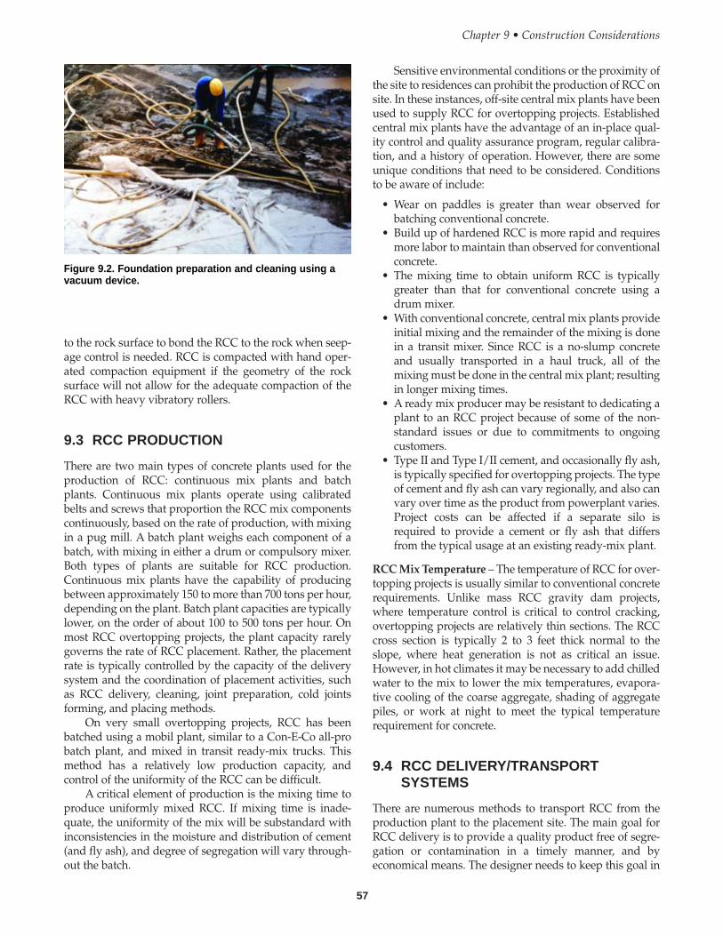
Sensitive environmental conditions or the proximity ofthe site to residences can prohibit the production of RCC onsite. In these instances, off-site central mix plants have beenused to supply RCC for overtopping projects. Establishedcentral mix plants have the advantage of an in-place qual-ity control and quality assurance program, regular calibra-tion, and a history of operation. However, there are someunique conditions that need to be considered. Conditionsto be aware of include:
• Wear on paddles is greater than wear observed forbatching conventional concrete.
• Build up of hardened RCC is more rapid and requiresmore labor to maintain than observed for conventionalconcrete.
• The mixing time to obtain uniform RCC is typicallygreater than that for conventional concrete using adrum mixer.
• With conventional concrete, central mix plants provideinitial mixing and the remainder of the mixing is donein a transit mixer. Since RCC is a no-slump concreteand usually transported in a haul truck, all of themixing must be done in the central mix plant; resultingin longer mixing times.
• A ready mix producer may be resistant to dedicating aplant to an RCC project because of some of the non-standard issues or due to commitments to ongoingcustomers.
• Type II and Type I/II cement, and occasionally fly ash,is typically specified for overtopping projects. The typeof cement and fly ash can vary regionally, and also canvary over time as the product from powerplant varies.Project costs can be affected if a separate silo isrequired to provide a cement or fly ash that differsfrom the typical usage at an existing ready-mix plant.
RCC Mix Temperature – The temperature of RCC for over-topping projects is usually similar to conventional concreterequirements. Unlike mass RCC gravity dam projects,where temperature control is critical to control cracking,overtopping projects are relatively thin sections. The RCCcross section is typically 2 to 3 feet thick normal to theslope, where heat generation is not as critical an issue.However, in hot climates it may be necessary to add chilledwater to the mix to lower the mix temperatures, evapora-tive cooling of the coarse aggregate, shading of aggregatepiles, or work at night to meet the typical temperaturerequirement for concrete.
9.4 RCC DELIVERY/TRANSPORTSYSTEMS
There are numerous methods to transport RCC from theproduction plant to the placement site. The main goal forRCC delivery is to provide a quality product free of segre-gation or contamination in a timely manner, and byeconomical means. The designer needs to keep this goal in
57
to the rock surface to bond the RCC to the rock when seep-age control is needed. RCC is compacted with hand oper-ated compaction equipment if the geometry of the rocksurface will not allow for the adequate compaction of theRCC with heavy vibratory rollers.
9.3 RCC PRODUCTION
There are two main types of concrete plants used for theproduction of RCC: continuous mix plants and batchplants. Continuous mix plants operate using calibratedbelts and screws that proportion the RCC mix componentscontinuously, based on the rate of production, with mixingin a pug mill. A batch plant weighs each component of abatch, with mixing in either a drum or compulsory mixer.Both types of plants are suitable for RCC production.Continuous mix plants have the capability of producingbetween approximately 150 to more than 700 tons per hour,depending on the plant. Batch plant capacities are typicallylower, on the order of about 100 to 500 tons per hour. Onmost RCC overtopping projects, the plant capacity rarelygoverns the rate of RCC placement. Rather, the placementrate is typically controlled by the capacity of the deliverysystem and the coordination of placement activities, suchas RCC delivery, cleaning, joint preparation, cold jointsforming, and placing methods.
On very small overtopping projects, RCC has beenbatched using a mobil plant, similar to a Con-E-Co all-probatch plant, and mixed in transit ready-mix trucks. Thismethod has a relatively low production capacity, andcontrol of the uniformity of the RCC can be difficult.
A critical element of production is the mixing time toproduce uniformly mixed RCC. If mixing time is inade-quate, the uniformity of the mix will be substandard withinconsistencies in the moisture and distribution of cement(and fly ash), and degree of segregation will vary through-out the batch.
Chapter 9 • Construction Considerations
Figure 9.2. Foundation preparation and cleaning using avacuum device.
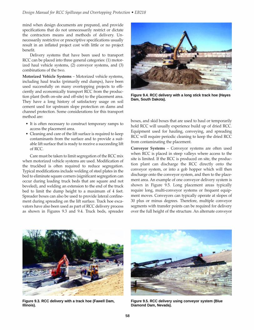
58
Design Manual for RCC Spillways and Overtopping Protection • EB218
boxes, and skid boxes that are used to haul or temporarilyhold RCC will usually experience build up of dried RCC.Equipment used for hauling, conveying, and spreadingRCC will require periodic cleaning to keep the dried RCCfrom contaminating the placement.
Conveyor Systems – Conveyor systems are often usedwhen RCC is placed in steep valleys where access to thesite is limited. If the RCC is produced on site, the produc-tion plant can discharge the RCC directly onto theconveyor system, or into a gob hopper which will thendischarge onto the conveyor system, and then to the place-ment area. An example of one conveyor delivery system isshown in Figure 9.5. Long placement areas typicallyrequire long, multi-conveyor systems or frequent equip-ment moves. Conveyors can typically operate at slopes of30 plus or minus degrees. Therefore, multiple conveyorsegments with transfer points can be required for deliveryover the full height of the structure. An alternate conveyor
mind when design documents are prepared, and providespecifications that do not unnecessarily restrict or dictatethe contractors means and methods of delivery. Un-necessarily restrictive or prescriptive specifications usuallyresult in an inflated project cost with little or no projectbenefit.
Delivery systems that have been used to transportRCC can be placed into three general categories: (1) motor-ized haul vehicle systems, (2) conveyor systems, and (3)combinations of the two.Motorized Vehicle Systems – Motorized vehicle systems,including haul trucks (primarily end dumps), have beenused successfully on many overtopping projects to effi-ciently and economically transport RCC from the produc-tion plant (both on-site and off-site) to the placement area.They have a long history of satisfactory usage on soilcement used for upstream slope protection on dams andchannel protection. Some considerations for this transportmethod are:
• It is often necessary to construct temporary ramps toaccess the placement area.
• Cleaning and care of the lift surface is required to keepcontaminants from the surface and to provide a suit-able lift surface that is ready to receive a succeeding liftof RCC.
Care must be taken to limit segregation of the RCC mixwhen motorized vehicle systems are used. Modification ofthe truckbed is often required to reduce segregation.Typical modifications include welding of steel plates in thebed to eliminate square corners (significant segregation canoccur during loading truck beds that are square and notbeveled), and welding an extension to the end of the truckbed to limit the dump height to a maximum of 4 feet.Spreader boxes can also be used to provide lateral confine-ment during spreading on the lift surface. Track hoe exca-vators have also been used as part of RCC delivery processas shown in Figures 9.3 and 9.4. Truck beds, spreader
Figure 9.3. RCC delivery with a track hoe (Fawell Dam,Illinois).
Figure 9.5. RCC delivery using conveyor system (BlueDiamond Dam, Nevada).
Figure 9.4. RCC delivery with a long stick track hoe (HayesDam, South Dakota).
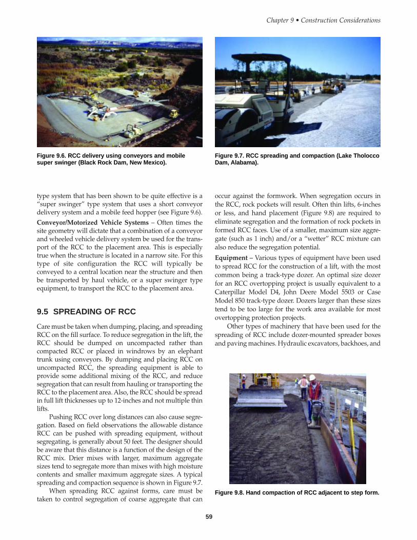
59
type system that has been shown to be quite effective is a“super swinger” type system that uses a short conveyordelivery system and a mobile feed hopper (see Figure 9.6). Conveyor/Motorized Vehicle Systems – Often times thesite geometry will dictate that a combination of a conveyorand wheeled vehicle delivery system be used for the trans-port of the RCC to the placement area. This is especiallytrue when the structure is located in a narrow site. For thistype of site configuration the RCC will typically beconveyed to a central location near the structure and thenbe transported by haul vehicle, or a super swinger typeequipment, to transport the RCC to the placement area.
9.5 SPREADING OF RCC
Care must be taken when dumping, placing, and spreadingRCC on the fill surface. To reduce segregation in the lift, theRCC should be dumped on uncompacted rather thancompacted RCC or placed in windrows by an elephanttrunk using conveyors. By dumping and placing RCC onuncompacted RCC, the spreading equipment is able toprovide some additional mixing of the RCC, and reducesegregation that can result from hauling or transporting theRCC to the placement area. Also, the RCC should be spreadin full lift thicknesses up to 12-inches and not multiple thinlifts.
Pushing RCC over long distances can also cause segre-gation. Based on field observations the allowable distanceRCC can be pushed with spreading equipment, withoutsegregating, is generally about 50 feet. The designer shouldbe aware that this distance is a function of the design of theRCC mix. Drier mixes with larger, maximum aggregatesizes tend to segregate more than mixes with high moisturecontents and smaller maximum aggregate sizes. A typicalspreading and compaction sequence is shown in Figure 9.7.
When spreading RCC against forms, care must betaken to control segregation of coarse aggregate that can
occur against the formwork. When segregation occurs inthe RCC, rock pockets will result. Often thin lifts, 6-inchesor less, and hand placement (Figure 9.8) are required toeliminate segregation and the formation of rock pockets informed RCC faces. Use of a smaller, maximum size aggre-gate (such as 1 inch) and/or a “wetter” RCC mixture canalso reduce the segregation potential.
Equipment – Various types of equipment have been usedto spread RCC for the construction of a lift, with the mostcommon being a track-type dozer. An optimal size dozerfor an RCC overtopping project is usually equivalent to aCaterpillar Model D4, John Deere Model 5503 or CaseModel 850 track-type dozer. Dozers larger than these sizestend to be too large for the work area available for mostovertopping protection projects.
Other types of machinery that have been used for thespreading of RCC include dozer-mounted spreader boxesand paving machines. Hydraulic excavators, backhoes, and
Chapter 9 • Construction Considerations
Figure 9.6. RCC delivery using conveyors and mobilesuper swinger (Black Rock Dam, New Mexico).
Figure 9.7. RCC spreading and compaction (Lake TholoccoDam, Alabama).
Figure 9.8. Hand compaction of RCC adjacent to step form.
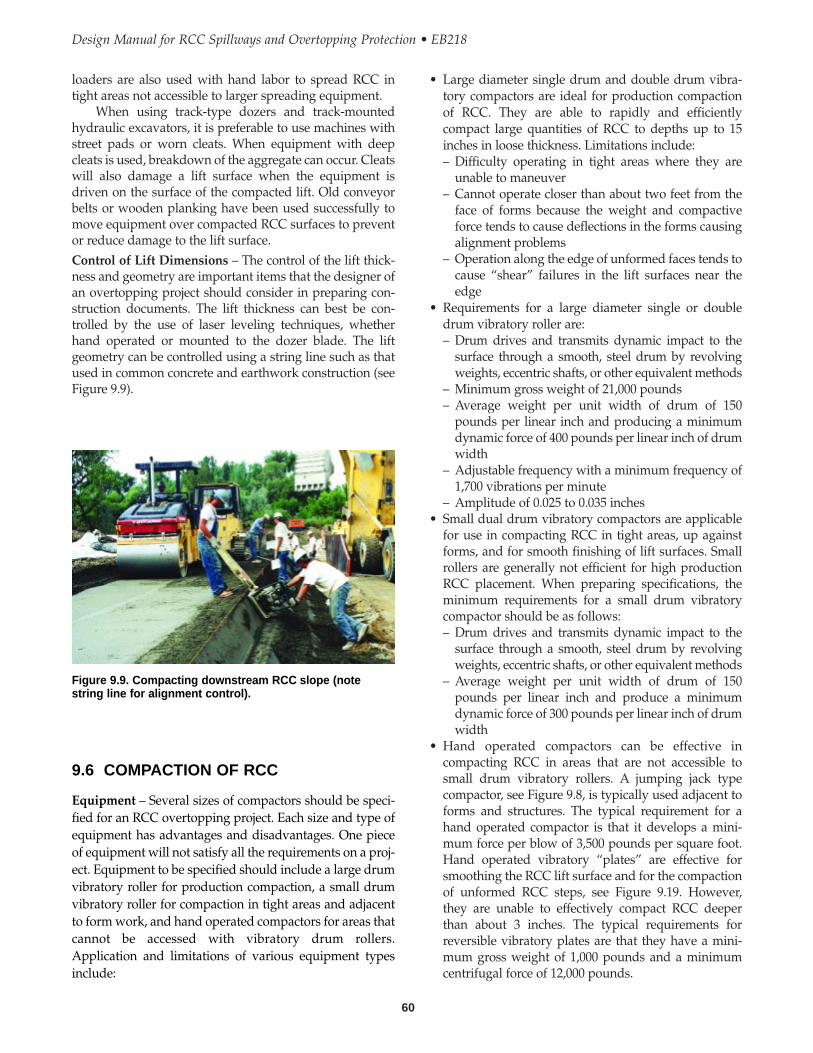
• Large diameter single drum and double drum vibra-tory compactors are ideal for production compactionof RCC. They are able to rapidly and efficientlycompact large quantities of RCC to depths up to 15inches in loose thickness. Limitations include:– Difficulty operating in tight areas where they are
unable to maneuver– Cannot operate closer than about two feet from the
face of forms because the weight and compactiveforce tends to cause deflections in the forms causingalignment problems
– Operation along the edge of unformed faces tends tocause “shear” failures in the lift surfaces near theedge
• Requirements for a large diameter single or doubledrum vibratory roller are:– Drum drives and transmits dynamic impact to the
surface through a smooth, steel drum by revolvingweights, eccentric shafts, or other equivalent methods
– Minimum gross weight of 21,000 pounds– Average weight per unit width of drum of 150
pounds per linear inch and producing a minimumdynamic force of 400 pounds per linear inch of drumwidth
– Adjustable frequency with a minimum frequency of1,700 vibrations per minute
– Amplitude of 0.025 to 0.035 inches• Small dual drum vibratory compactors are applicable
for use in compacting RCC in tight areas, up againstforms, and for smooth finishing of lift surfaces. Smallrollers are generally not efficient for high productionRCC placement. When preparing specifications, theminimum requirements for a small drum vibratorycompactor should be as follows: – Drum drives and transmits dynamic impact to the
surface through a smooth, steel drum by revolvingweights, eccentric shafts, or other equivalent methods
– Average weight per unit width of drum of 150pounds per linear inch and produce a minimumdynamic force of 300 pounds per linear inch of drumwidth
• Hand operated compactors can be effective incompacting RCC in areas that are not accessible tosmall drum vibratory rollers. A jumping jack typecompactor, see Figure 9.8, is typically used adjacent toforms and structures. The typical requirement for ahand operated compactor is that it develops a mini-mum force per blow of 3,500 pounds per square foot.Hand operated vibratory “plates” are effective forsmoothing the RCC lift surface and for the compactionof unformed RCC steps, see Figure 9.19. However,they are unable to effectively compact RCC deeperthan about 3 inches. The typical requirements forreversible vibratory plates are that they have a mini-mum gross weight of 1,000 pounds and a minimumcentrifugal force of 12,000 pounds.
60
Design Manual for RCC Spillways and Overtopping Protection • EB218
loaders are also used with hand labor to spread RCC intight areas not accessible to larger spreading equipment.
When using track-type dozers and track-mountedhydraulic excavators, it is preferable to use machines withstreet pads or worn cleats. When equipment with deepcleats is used, breakdown of the aggregate can occur. Cleatswill also damage a lift surface when the equipment isdriven on the surface of the compacted lift. Old conveyorbelts or wooden planking have been used successfully tomove equipment over compacted RCC surfaces to preventor reduce damage to the lift surface.Control of Lift Dimensions – The control of the lift thick-ness and geometry are important items that the designer ofan overtopping project should consider in preparing con-struction documents. The lift thickness can best be con-trolled by the use of laser leveling techniques, whetherhand operated or mounted to the dozer blade. The liftgeometry can be controlled using a string line such as thatused in common concrete and earthwork construction (seeFigure 9.9).
Figure 9.9. Compacting downstream RCC slope (notestring line for alignment control).
9.6 COMPACTION OF RCC
Equipment – Several sizes of compactors should be speci-fied for an RCC overtopping project. Each size and type ofequipment has advantages and disadvantages. One pieceof equipment will not satisfy all the requirements on a proj-ect. Equipment to be specified should include a large drumvibratory roller for production compaction, a small drumvibratory roller for compaction in tight areas and adjacentto form work, and hand operated compactors for areas thatcannot be accessed with vibratory drum rollers.Application and limitations of various equipment typesinclude:
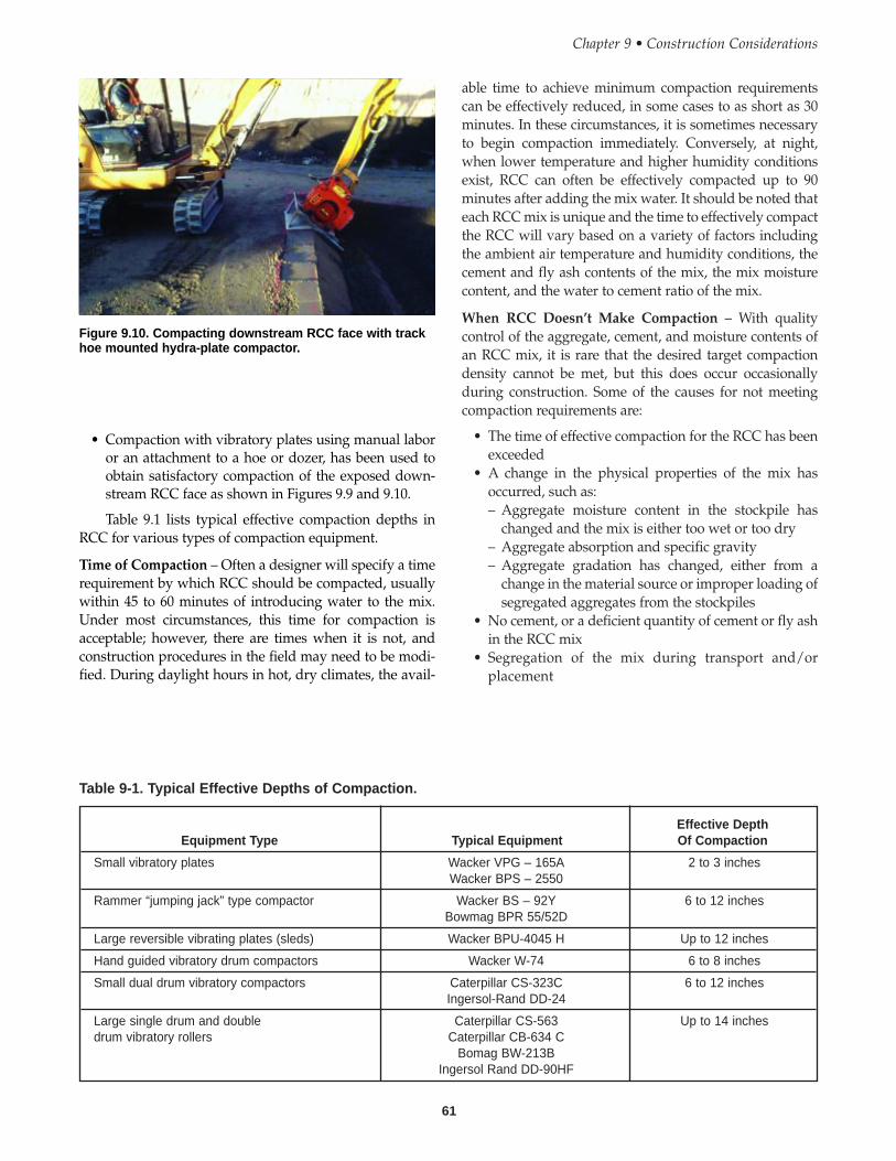
61
able time to achieve minimum compaction requirementscan be effectively reduced, in some cases to as short as 30minutes. In these circumstances, it is sometimes necessaryto begin compaction immediately. Conversely, at night,when lower temperature and higher humidity conditionsexist, RCC can often be effectively compacted up to 90minutes after adding the mix water. It should be noted thateach RCC mix is unique and the time to effectively compactthe RCC will vary based on a variety of factors includingthe ambient air temperature and humidity conditions, thecement and fly ash contents of the mix, the mix moisturecontent, and the water to cement ratio of the mix.
When RCC Doesn’t Make Compaction – With qualitycontrol of the aggregate, cement, and moisture contents ofan RCC mix, it is rare that the desired target compactiondensity cannot be met, but this does occur occasionallyduring construction. Some of the causes for not meetingcompaction requirements are:
• The time of effective compaction for the RCC has beenexceeded
• A change in the physical properties of the mix hasoccurred, such as:– Aggregate moisture content in the stockpile has
changed and the mix is either too wet or too dry– Aggregate absorption and specific gravity– Aggregate gradation has changed, either from a
change in the material source or improper loading ofsegregated aggregates from the stockpiles
• No cement, or a deficient quantity of cement or fly ashin the RCC mix
• Segregation of the mix during transport and/orplacement
Chapter 9 • Construction Considerations
Table 9-1. Typical Effective Depths of Compaction.
Effective DepthEquipment Type Typical Equipment Of Compaction
Small vibratory plates Wacker VPG – 165A 2 to 3 inchesWacker BPS – 2550
Rammer “jumping jack” type compactor Wacker BS – 92Y 6 to 12 inchesBowmag BPR 55/52D
Large reversible vibrating plates (sleds) Wacker BPU-4045 H Up to 12 inches
Hand guided vibratory drum compactors Wacker W-74 6 to 8 inches
Small dual drum vibratory compactors Caterpillar CS-323C 6 to 12 inchesIngersol-Rand DD-24
Large single drum and double Caterpillar CS-563 Up to 14 inchesdrum vibratory rollers Caterpillar CB-634 C
Bomag BW-213BIngersol Rand DD-90HF
Figure 9.10. Compacting downstream RCC face with trackhoe mounted hydra-plate compactor.
• Compaction with vibratory plates using manual laboror an attachment to a hoe or dozer, has been used toobtain satisfactory compaction of the exposed down-stream RCC face as shown in Figures 9.9 and 9.10.
Table 9.1 lists typical effective compaction depths inRCC for various types of compaction equipment.
Time of Compaction – Often a designer will specify a timerequirement by which RCC should be compacted, usuallywithin 45 to 60 minutes of introducing water to the mix.Under most circumstances, this time for compaction isacceptable; however, there are times when it is not, andconstruction procedures in the field may need to be modi-fied. During daylight hours in hot, dry climates, the avail-
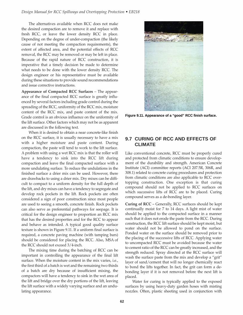
The alternatives available when RCC does not makethe desired compaction are to remove it and replace withfresh RCC, or leave the lower density RCC in place.Depending on the degree of under-compaction (the likelycause of not meeting the compaction requirements), theextent of affected area, and the potential effects of RCCremoval, the RCC may be removed or may be left in place.Because of the rapid nature of RCC construction, it isimperative that a timely decision be made to determinewhat needs to be done with the lower density RCC. Thedesign engineer or his representative must be availableduring these situations to provide sound recommendationsand issue corrective instructions.
Appearance of Compacted RCC Surfaces – The appear-ance of the final compacted RCC surface is greatly influ-enced by several factors including grade control during thespreading of the RCC, uniformity of the RCC mix, moisturecontent of the RCC mix, and paste content of the mix.Grade control is an obvious influence on the uniformity ofthe lift surface. Other factors which may not be as apparentare discussed in the following text.
When it is desired to obtain a near concrete-like finishon the RCC surface, it is usually necessary to have a mixwith a higher moisture and paste content. Duringcompaction, the paste will tend to work to the lift surface.A problem with using a wet RCC mix is that the roller willhave a tendency to sink into the RCC lift duringcompaction and leave the final compacted surface with amore undulating surface. To reduce the undulations in thefinished surface a drier mix can be used. However, thereare drawbacks to using a drier mix. Dry mixes can be diffi-cult to compact to a uniform density for the full depth ofthe lift, and dry mixes can have a tendency to segregate anddevelop rock pockets in the lift. Rock pockets are oftenconsidered a sign of poor construction since most peopleare used to seeing a smooth, concrete finish. Rock pocketscan also serve as preferential pathways for seepage. It iscritical for the design engineer to proportion an RCC mixthat has the desired properties and for the RCC to appearand behave as intended. A typical good quality surfacetexture is shown in Figure 9.11. If a uniform final surface isrequired, a concrete paving machine (with tamping bars)should be considered for placing the RCC. Also, MSA ofthe RCC should not exceed 3/4-inch.
The mixing time during the batching of RCC can beimportant in controlling the appearance of the final liftsurface. When the moisture content in the mix varies, i.e.,the first third of a batch is wet and the remaining two thirdsof a batch are dry because of insufficient mixing, thecompactors will have a tendency to sink in the wet area ofthe lift and bridge over the dry portions of the lift, leavingthe lift surface with a widely varying surface and an undu-lating appearance.
62
Design Manual for RCC Spillways and Overtopping Protection • EB218
9.7 CURING OF RCC AND EFFECTS OFCLIMATE
Like conventional concrete, RCC must be properly curedand protected from climatic conditions to ensure develop-ment of the durability and strength. American ConcreteInstitute (ACI) committee reports (ACI 207.5R, 306R, and308.1) related to concrete curing procedures and protectionfrom climatic conditions are also applicable to RCC over-topping construction. One exception is that curingcompound should not be applied to RCC surfaces onwhich successive lifts of RCC are to be placed. Curingcompound serves as a de-bonding layer.
Curing of RCC – Generally, RCC surfaces should be keptcontinually moist for 7 to 14 days. A light mist of watershould be applied to the compacted surface in a mannersuch that it does not erode the paste from the RCC. Duringconstruction, the RCC lift surface should be kept moist, butwater should not be allowed to pond on the surface.Ponded water on the surface should be removed prior tothe placing of the successive lifts of RCC. Applying waterto uncompacted RCC must be avoided because the waterto cement ratio of the RCC can be greatly increased, and thestrength reduced. Spray directed at the RCC surface willwash the surface paste from the mix and develop a “grit”layer of sand/cement that will no longer chemically reactto bond the lifts together. In fact, the grit can form a de-bonding layer if it is not removed before the next lift isplaced.
Water for curing is typically applied to the exposedsurfaces by using heavy-duty garden hoses with mistingnozzles. Often, plastic sheeting used in conjunction with
Figure 9.11. Appearance of a “good” RCC finish surface.
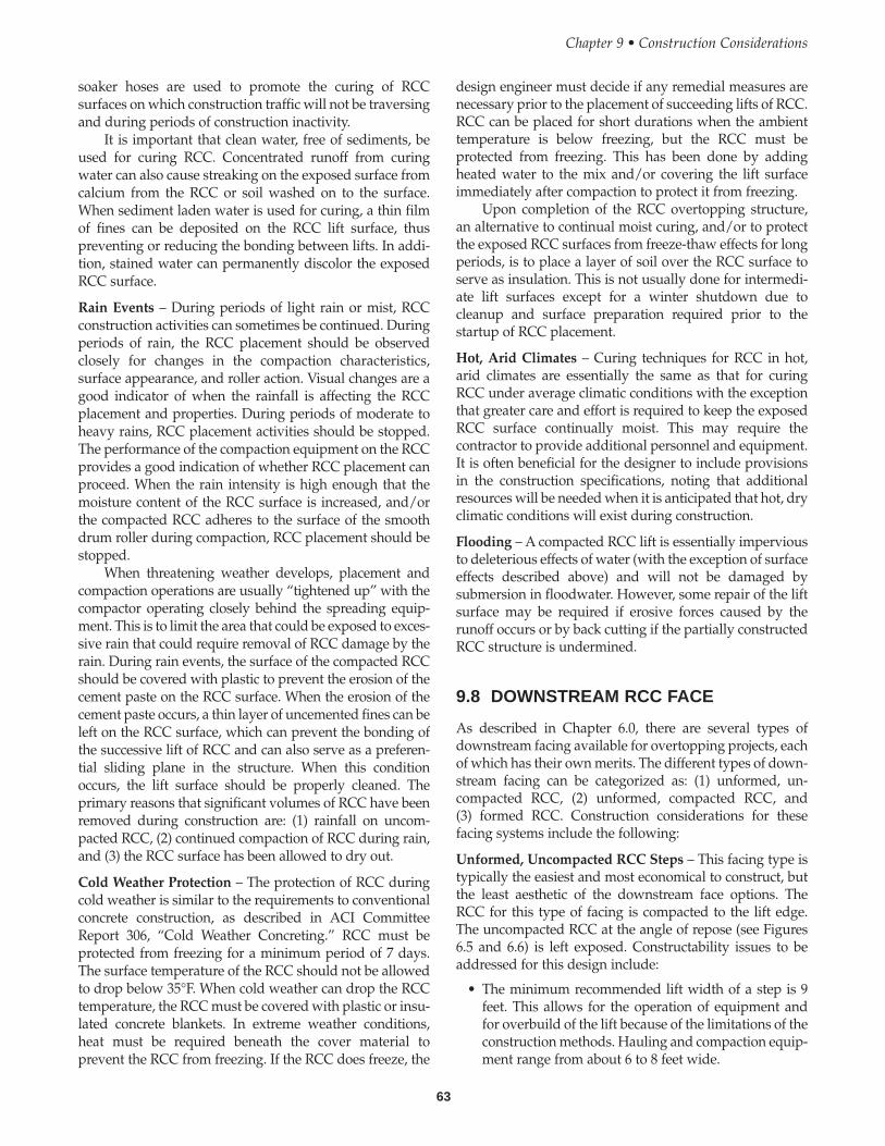
soaker hoses are used to promote the curing of RCCsurfaces on which construction traffic will not be traversingand during periods of construction inactivity.
It is important that clean water, free of sediments, beused for curing RCC. Concentrated runoff from curingwater can also cause streaking on the exposed surface fromcalcium from the RCC or soil washed on to the surface.When sediment laden water is used for curing, a thin filmof fines can be deposited on the RCC lift surface, thuspreventing or reducing the bonding between lifts. In addi-tion, stained water can permanently discolor the exposedRCC surface.
Rain Events – During periods of light rain or mist, RCCconstruction activities can sometimes be continued. Duringperiods of rain, the RCC placement should be observedclosely for changes in the compaction characteristics,surface appearance, and roller action. Visual changes are agood indicator of when the rainfall is affecting the RCCplacement and properties. During periods of moderate toheavy rains, RCC placement activities should be stopped.The performance of the compaction equipment on the RCCprovides a good indication of whether RCC placement canproceed. When the rain intensity is high enough that themoisture content of the RCC surface is increased, and/orthe compacted RCC adheres to the surface of the smoothdrum roller during compaction, RCC placement should bestopped.
When threatening weather develops, placement andcompaction operations are usually “tightened up” with thecompactor operating closely behind the spreading equip-ment. This is to limit the area that could be exposed to exces-sive rain that could require removal of RCC damage by therain. During rain events, the surface of the compacted RCCshould be covered with plastic to prevent the erosion of thecement paste on the RCC surface. When the erosion of thecement paste occurs, a thin layer of uncemented fines can beleft on the RCC surface, which can prevent the bonding ofthe successive lift of RCC and can also serve as a preferen-tial sliding plane in the structure. When this conditionoccurs, the lift surface should be properly cleaned. Theprimary reasons that significant volumes of RCC have beenremoved during construction are: (1) rainfall on uncom-pacted RCC, (2) continued compaction of RCC during rain,and (3) the RCC surface has been allowed to dry out.
Cold Weather Protection – The protection of RCC duringcold weather is similar to the requirements to conventionalconcrete construction, as described in ACI CommitteeReport 306, “Cold Weather Concreting.” RCC must beprotected from freezing for a minimum period of 7 days.The surface temperature of the RCC should not be allowedto drop below 35°F. When cold weather can drop the RCCtemperature, the RCC must be covered with plastic or insu-lated concrete blankets. In extreme weather conditions,heat must be required beneath the cover material toprevent the RCC from freezing. If the RCC does freeze, the
design engineer must decide if any remedial measures arenecessary prior to the placement of succeeding lifts of RCC.RCC can be placed for short durations when the ambienttemperature is below freezing, but the RCC must beprotected from freezing. This has been done by addingheated water to the mix and/or covering the lift surfaceimmediately after compaction to protect it from freezing.
Upon completion of the RCC overtopping structure,an alternative to continual moist curing, and/or to protectthe exposed RCC surfaces from freeze-thaw effects for longperiods, is to place a layer of soil over the RCC surface toserve as insulation. This is not usually done for intermedi-ate lift surfaces except for a winter shutdown due tocleanup and surface preparation required prior to thestartup of RCC placement.
Hot, Arid Climates – Curing techniques for RCC in hot,arid climates are essentially the same as that for curingRCC under average climatic conditions with the exceptionthat greater care and effort is required to keep the exposedRCC surface continually moist. This may require thecontractor to provide additional personnel and equipment.It is often beneficial for the designer to include provisionsin the construction specifications, noting that additionalresources will be needed when it is anticipated that hot, dryclimatic conditions will exist during construction.
Flooding – A compacted RCC lift is essentially imperviousto deleterious effects of water (with the exception of surfaceeffects described above) and will not be damaged bysubmersion in floodwater. However, some repair of the liftsurface may be required if erosive forces caused by therunoff occurs or by back cutting if the partially constructedRCC structure is undermined.
9.8 DOWNSTREAM RCC FACE
As described in Chapter 6.0, there are several types ofdownstream facing available for overtopping projects, eachof which has their own merits. The different types of down-stream facing can be categorized as: (1) unformed, un-compacted RCC, (2) unformed, compacted RCC, and(3) formed RCC. Construction considerations for thesefacing systems include the following:
Unformed, Uncompacted RCC Steps – This facing type istypically the easiest and most economical to construct, butthe least aesthetic of the downstream face options. TheRCC for this type of facing is compacted to the lift edge.The uncompacted RCC at the angle of repose (see Figures6.5 and 6.6) is left exposed. Constructability issues to beaddressed for this design include:
• The minimum recommended lift width of a step is 9feet. This allows for the operation of equipment andfor overbuild of the lift because of the limitations of theconstruction methods. Hauling and compaction equip-ment range from about 6 to 8 feet wide.
63
Chapter 9 • Construction Considerations
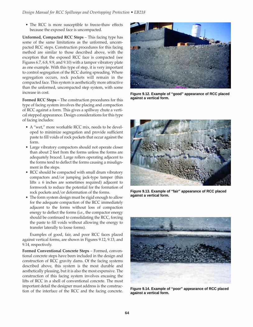
64
Design Manual for RCC Spillways and Overtopping Protection • EB218
• The RCC is more susceptible to freeze-thaw effectsbecause the exposed face is uncompacted.
Unformed, Compacted RCC Steps – This facing type hassome of the same limitations as the unformed, uncom-pacted RCC steps. Construction procedures for this facingmethod are similar to those described above, with theexception that the exposed RCC face is compacted (seeFigures 6.7, 6.8, 9.9, and 9.10) with a tampor vibratory plateas one example. With this type of step, it is very importantto control segregation of the RCC during spreading. Wheresegregation occurs, rock pockets will remain in thecompacted face. This system is aesthetically more attractivethan the unformed, uncompacted step system, with someincrease in cost.
Formed RCC Steps – The construction procedures for thistype of facing system involves the placing and compactionof RCC against a form. This gives a spillway chute a verti-cal stepped appearance. Design considerations for this typeof facing includes:
• A “wet,” more workable RCC mix, needs to be devel-oped to minimize segregation and provide sufficientpaste to fill voids of rock pockets that occur against theform.
• Large vibratory compactors should not operate closerthan about 2 feet from the forms unless the forms areadequately braced. Large rollers operating adjacent tothe forms tend to deflect the forms causing a misalign-ment in the steps.
• RCC should be compacted with small drum vibratorycompactors and/or jumping jack-type tamper (thinlifts ± 6 inches are sometimes required) adjacent toformwork to reduce the potential for the formation ofrock pockets and/or deformation of the forms.
• The form system design must be rigid enough to allowfor the adequate compaction of the RCC immediatelyadjacent to the forms without loss of compactionenergy to deflect the forms (i.e., the compactor energyshould be continued to consolidating the RCC, forcingthe paste to fill voids without allowing the energy totransfer laterally to loose forms).
Examples of good, fair, and poor RCC faces placedagainst vertical forms, are shown in Figures 9.12, 9.13, and9.14, respectively.
Formed Conventional Concrete Steps – Formed, conven-tional concrete steps have been included in the design andconstruction of RCC gravity dams. Of the facing systemsdescribed above, this system is the most durable andaesthetically pleasing, but it is also the most expensive. Theconstruction of this facing system involves encasing thelifts of RCC in a shell of conventional concrete. The mostimportant detail the designer must address is the construc-tion of the interface of the RCC and the facing concrete.
Figure 9.12. Example of “good” appearance of RCC placedagainst a vertical form.
Figure 9.13. Example of “fair” appearance of RCC placedagainst a vertical form.
Figure 9.14. Example of “poor” appearance of RCC placedagainst a vertical form.

Debate is ongoing as to the proper sequencing of the place-ment of the RCC and facing interface. Dams have beenconstructed using the following procedures:
• A stiff-facing concrete is placed adjacent to the form-work and then vibrated in a restrained condition. RCCis spread adjacent to the facing, and the interface of thefacing and RCC are vibrated together. The RCC is thencompacted with a large drum vibratory roller.
• Alternately, the RCC is spread and a trough left adja-cent to the forms. Facing concrete is placed in thetrough and the RCC facing interface is vibratedtogether using immersion vibrators. The RCC is thencompacted.
Both construction procedures have been used success-fully for the purpose of construction of downstream stepson gravity dams.
This method has not typically been used on the flatterslopes of RCC overtopping protection projects.
Formed, Grout Enriched RCC Steps – This concept forconstructing facing for RCC was generally developed inChina, and is relatively new to the U.S. Aesthetically, thisconstruction method is similar to formed, conventionalconcrete steps. The overall material costs are lower, butlabor effort and costs are therefore higher. One generalprocedure for formed, grout enriched RCC steps would beas follows:
1. A cement grout (cement and water) is placed on theprevious lift surface out a distance of about 2 feet fromthe face of the form.
2. Loose uncompacted RCC is placed up to the form.3. The cement grout is then applied to the surface of the
uncompacted RCC.4. Immersion vibrators are then used to mobilize the
grout and RCC into a fluid, concrete mixture.
Test trials are needed to refine the construction proce-dures and to determine the quantity of cement paste perlinear foot of facing to add to the uncompacted RCC, toproduce the desired engineering properties.
A couple of alternative “grout enriched” placementmethods that have shown some promise in a test sectiontrial are: (1) grout sprayed into the RCC mix as it is beingspread adjacent to a form face, and (2) injection into theRCC after it has been spread, and prior to compaction.
9.9 CONTROL JOINTS
The purpose of control joints is to control the location of thecracks. Control joints or crack inducers, have beenconstructed and installed using different materials andconstruction techniques. The types of materials used forcontrol joints have generally included:
• Steel metal plates driven into or buried in the lift (seeFigures 9.15 and 9.16)
65
• Plastic sheeting buried into the lift as shown in Figure9.17
• Saw cuts• Monolithic construction with bond breakers
The decision as to the type of material to use forconstruction of a control is generally based on thedesigner’s preference. Steel sheets driven into the liftsurface appear to be the most efficient method of installinga control joint from a construction production view point.Saw cuts are not recommended because the crack formed inthe RCC tends to be wider than the other methods whichcould increase the potential for fines to migrate through theRCC. If saw cut joints are used, the design should include afilter beneath the joint location, and saw cutting must be ofsufficient depth to control cracking at the design location.
Experience has shown that more than 50 percent of thelift thickness needs to be penetrated to form a crack.Therefore, the designer should consider placing the steelsheet metal plates as crack inducers in every lift using aplate height of between 8 and 10 inches.
Chapter 9 • Construction Considerations
Figure 9.15. Installation of control joint plate.
Figure 9.16. Control joint plate placed during RCC placing.
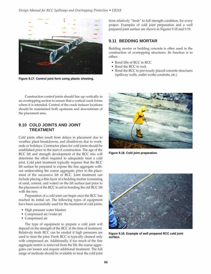
66
Design Manual for RCC Spillways and Overtopping Protection • EB218
from relatively “fresh” to full strength condition, for everyproject. Examples of cold joint preparation and a wellprepared joint surface are shown in Figures 9.18 and 9.19.
9.11 BEDDING MORTAR
Bedding mortar or bedding concrete is often used in theconstruction of overtopping structures. Its function is toeither:
• Bond lifts of RCC to RCC• Bond the RCC to rock • Bond the RCC to previously placed concrete structures
(spillway walls, outlet works conduits, etc.)
Construction control joints should line up vertically inan overtopping section to ensure that a vertical crack formswhere it is intended. Control of the crack inducer locationsshould be maintained both upstream and downstream ofthe placement area.
9.10 COLD JOINTS AND JOINTTREATMENT
Cold joints often result from delays in placement due toweather, plant breakdowns, and shutdowns due to week-ends or holidays. Contractor plans for cold joints should beestablished prior to the start of construction. The age of theRCC lift and strength development of the RCC mix willdetermine the effort required to adequately treat a coldjoint. Cold joint treatment typically requires that the RCClift surface be prepared to expose the fine aggregate with-out undercutting the coarse aggregate, prior to the place-ment of the successive lift of RCC. Joint treatment caninclude placing a thin layer of a bedding mortar (consistingof sand, cement, and water) on the lift surface just prior tothe placement of the RCC to aid in bonding the old RCC liftwith the new.
Preparation of a cold joint can begin once the RCC hasreached its initial set. The following types of equipmenthave been successfully used for the treatment of cold joints:
• High pressure water blasters• Compressed air/water jet• Compressed air
The type of equipment to prepare a cold joint willdepend on the strength of the RCC at the time of treatment.Relatively fresh RCC can be eroded if high pressures areused to treat the joint. Fresh RCC is typically cleaned onlywith compressed air. Additionally, if too much of the fineaggregate matrix is removed from the lift, the coarse aggre-gates can loosen and require additional treatment. The fullrange of methods should be available to treat the cold joint
Figure 9.17. Control joint form using plastic sheeting.
Figure 9.18. Cold joint preparation.
Figure 9.19. Example of well prepared RCC cold jointsurface.

67
Typically, bedding mortar is a mixture of sand, cement,water, and set retarder. Occasionally, fly ash and air en-trainment are added to the mix to improve its workabilityand reduce segregation. Bedding mortar is spread in thinlifts of about 1/4 to 1/2 inch in thickness. The maximumaggregate size is typically about 3/8-inch. The beddingmortar typically has a 28-day compressive strength of 2,000to 3,000 psi and at a minimum, equals the compressivestrength of the RCC. The bedding mortar is designed witha slump of about 8 to 10 inches. Bedding mortar placementis shown in Figure 9.20. When small quantities of beddingmortar are required, contractors often will utilize small1/4 yd3 mixers.
9.13 CONSTRUCTION JOINTS AT WORKSTOPPAGES
It is rare that an RCC overtopping project is constructedcontinuously without interruptions in the placementschedule. Therefore the designer must specify the type ofconstruction joint treatment that will be required at workstoppages.
Typically, the designer will require the contractor toprovide controlled construction joints at work stoppages asfollows:
• Transverse joints at work stoppages are trimmedthrough compacted RCC to form a straight, beveledjoint at an inclination of not more than 1 horizontal to1 vertical. Exposed surface of the joint is to becompacted after trimming.
• When lanes or areas of RCC are placed in adjacentareas, the longitudinal joint is typically required to betrimmed and compacted.
• Transverse joints of adjacent lanes are typically offsetby a distance of 15 to 20 feet to prevent the establish-ment of preferential seepage paths in the structure.
9.14 CONSTRUCTION OF TRANSITIONAREAS
RCC overtopping projects typically consist of modificationof existing embankment structures. Within these structuresthere are zones where the new RCC material will transitionwith existing components, including the earth embank-ment and abutments, rock abutment or foundations, outletworks conduit, spillway training walls, and other miscella-neous concrete structures (see Figure 9.21). Some construc-tion considerations the designer should consider inplanning an overtopping project are described below.
Chapter 9 • Construction Considerations
Figure 9.20. Bedding mortar placement.
Figure 9.21. RCC transition area construction.
9.12 LIFT TREATMENT
RCC construction is composed of successive horizontal liftsurfaces. For each successive lift to bond to the previouslyplaced lift, the surface of that lift needs to be clean and freeof loose uncompacted RCC, laitance, contaminants, dust,and water. The designer should specify that each lift becleaned with compressed air, at a minimum, prior to theplacement of RCC for the next lift. Techniques used in thepast include the use of blow pipes (with and withoutwater) attached to air compressors, vacuum trucks, andhand tools including push brooms and shovels.
At a minimum, joint treatment with a bedding mortarshould be implemented: (1) for lift surfaces more than 24hours old, and (2) between the top three lifts of the over-topping section. Joint treatment for lift surfaces less than 24hours old is still an area of designer preference, without anobvious standard at this time.
9.15 RCC CONSTRUCTION IN CONFINEDAREAS
When starting RCC placement for an overtopping project,the first lift is often too small for standard productionequipment to operate on. RCC can be placed and com-pacted in tight areas using small-scale compaction equip-ment, small backhoes, and hand operated equipment. Ingeneral, this type of construction can be slow and not prac-tical. An alternative for working in a tight area is to place aconventional concrete starter slab at an elevation to whichproduction equipment can more readily operate. RCCproduction can then start once the slab has gainedadequate strength on which to operate equipment.
When the first lift of RCC is placed on a soil founda-tion, it can be difficult to obtain the specified compaction asthe result of the subgrade yielding. The designer canaccount for this condition.
• Assuming that the first RCC lift is a somewhat sacrifi-cial lift meeting a lower density than specified for thesuccessive lifts.
• A mud slab or starter slab of conventional concrete canbe built to begin RCC placement.
Both of these methods have been used successfully inthe construction of existing RCC overtopping projects.
9.16 REPAIR OF RCC
Because of the nature of RCC, when first produced, itbehaves as a base course material and over time takes onthe properties of hardened concrete. The method and levelof effort to repair RCC is therefore dependent on its age. Ifsubstandard RCC is to be removed, the decision should bemade in a timely manner (as described in Section 9.6). Theeffort to remove fresh RCC is considerably less than theeffort to remove RCC that has hardened and set with time.Judgement should be used in the determination of thenecessity to remove compacted RCC. The engineer mustconsider that, at times, it may be desirable to leave slightlysubstandard RCC in-place and undisturbed, rather thandamage the surrounding “good” RCC, if the area consid-ered for removal is of limited extent or in a non-criticalsection of the structure.
Repair of Fresh RCC – The repair of fresh RCC can benecessitated for some the following reasons:
• Too much or too little water• Inability to obtain the target compaction• Bearing failure of the lift edge caused by the vibratory
roller operating too close to the edge of the lift duringcompaction
• The presence of pockets of segregated coarse aggre-gates in the lift
• Lack of the proper quantity of cementitious material
RCC to Embankment Transitions – These transitions arebest handled using two very different but effectiveconstruction techniques:
• Sculpting RCC at the interface zone, or • Constructing a discrete interface zone with a concrete
training wall.
When RCC is “sculpted” at the embankment interface,the designer must consider the methods used to place andcompact the RCC, including dozers and vibratory rollers.Various types of production equipment have difficultyoperating in tight areas because of their turning radii, anddamage to the already compacted RCC can occur.Production in this zone is typically the slowest on the proj-ect. RCC is difficult to place in turning (curving) and taper-ing lifts, and is slow. As part of the design, the interfacebetween the embankment and the RCC needs to beprotected from erosion, including sheet runoff, and erosionduring the flood event, including headcutting and back-cutting. This is often done by either constructing RCC wingwalls or dikes or placing riprap or similar slope protection.
The interface between the RCC and the embankmentand earth abutments can also be constructed using conven-tional concrete walls. These tend to be the easiest andquickest to construct, but their cost effectiveness must beevaluated. RCC can easily be placed and compactedagainst concrete walls. Conventional concrete walls havealso been constructed on the completed RCC surface.
RCC to Rock Transition Areas – When RCC is placedagainst rock abutments or foundation contacts, the mainconsideration the designer must address is if a watertightbond needs to be developed between the RCC and rock. Ifnot, RCC should be placed against the cleaned rock surface.Prior to RCC placement, all loose rock is typically barredoff, and the surface to receive the RCC is blown off withcompressed air blowpipes or cleaned with a vacuumdevice (see Figure 9.2). If the interface is to be “water tight,”such as at or near the crest or abutment interface, a greaterdegree of preparation should be done. Typically, all looserock is removed using pry bars and hand labor, and air andwater is used to clean the rock surface of dust and fines. Allresidual water is removed from the undulations in the rock,and a layer of bedding mortar is applied to the rock. RCCis then placed and compacted up against the bedding/rock.
Transition between RCC and Existing Structures – At theinterface between existing walls and conduits, the designermust evaluate if a bond between the existing structure andthe RCC is required. If a bond is required, the existingstructure should be sandblasted, cleaned with water, and abedding mortar placed between the RCC and the structure.If a bond is not required, the designer can allow the RCC tobe placed against the structure once all dirt and contami-nants have been removed from the surface.
68
Design Manual for RCC Spillways and Overtopping Protection • EB218
When it is necessary to remove and repair fresh RCC,considerable effort can be required to do it properly,depending on the quantity required to be removed. If it isrequired to replace a large volume of RCC, it is usuallyfavorable to remove the bulk of the material with heavyequipment, and then remove the remainder of the materialby hand. If the removal of a small volume of RCC isrequired, it is usually preferable to remove the materialwith a jack hammer, pneumatic spade, or other hand tool.The following are steps that are typically done for therepair of fresh RCC:
1. Delineate the area of substandard RCC for removaland use marking paint to outline this area.
2. If the area of removal is large, use a piece of heavyequipment such as a loader or backhoe to remove thebulk of the substandard RCC. If the area is small, usehand tools, a jackhammer or power spade to removethe bulk of the RCC.
3. Trim the edges of the RCC adjacent to the removedRCC at a 90 degree angle such that the new RCC canbe effectively compacted against the old RCC.
4. Remove any loose and uncompacted RCC from thetrimmed edge and the lift surface with brooms, shov-els, and/or compressed air.
5. Place and compact new RCC in the prepared area. Thetype of compaction equipment to use will depend onthe available space, but it is preferable to use thelargest piece available that can operate in the area. If itis necessary to have a bond between the old and thenew RCC, the engineer will need to require the con-tractor to place bedding mortar against the trimmededge just prior to the placement of the new RCC.
Repair of Old RCC – The repair of old RCC is necessitatedby the same reasons as the repair of fresh RCC except thatthe RCC has been allowed to set. Considerable effort willbe required by the contractor to remove RCC that has beenallowed to set. If possible, it is much preferred by bothcontractor and designer to remove RCC, if necessary, whenit is fresh and not hard. The procedure for the repair of oldRCC will be the same as that for the repair of fresh RCCwith the exception of the following:
1. The RCC may have sufficient strength, such that aloader or a backhoe is unable to remove the RCC. Inthis case it will be necessary to chip out the hardenedRCC with a jackhammer.
2. The prepared surface to receive RCC should bewashed with water to remove any dust and fines thatwill prevent the fresh RCC from bonding to the oldRCC.
3. A bedding mortar should be used to provide betterbonding between the prepared RCC surface and thenew RCC lift.
Repair of RCC with Conventional Concrete – Occa-sionally during the construction of an overtopping project,
the contractor will request to be allowed to repair RCC intight areas by replacing it with conventional concrete. Thissubstitution is generally adequate but the following mustbe considered when allowing this substitution:
• The compressive strength of the conventional concretemust be equal to or greater than that of the RCC.
• Consideration must be given to the aesthetics of thesubstitution. A change in appearance between the RCCand conventional concrete may occur if there is asignificant difference in the cement content and theaggregate sources of the two materials.
The procedures for repairing RCC with conventionalconcrete should be the same as those for repairing freshRCC or old RCC, as stated above.
Treatment of Rock Pockets – Occasionally during theplacement of RCC, rock pockets will occur on the liftsurface and on the exposed face of formed and unformedcompacted faces as a result of segregation of the RCC mix.The following should be considered for these areas:
Rock Pockets on Lift Surfaces – Occasionally duringplacements, rock pockets will be observed on the surface ofan RCC lift. Treatment of this condition can be handled intwo ways. The preferred way is for the contractor toremove the segregated aggregate from the lift using handtools prior to the compaction of the lift. Alternatively, if thelift has been compacted, the contractor should remove thezone of segregated aggregate immediately after compac-tion, to a minimum depth of 4 inches, and the segregatedmaterial shall be replaced with fresh compacted RCC.
Rock Pockets in Compacted Unformed Faces – When rockpockets are discovered in compacted, unformed faces, theoptions for repair are as follows:
1. If the RCC is fresh, the rock pocket can be removed andreplaced with new unsegregated RCC. Because thearea will be small, hand compaction of the RCC will berequired. The contractor must take care and havepatience in placing and compacting the RCC in thin3-4 inch lifts because of the limitations of thecompaction methods.
2. If the RCC has set, the contractor may chip out thesegregated material and place a patch (sand andmortar or a polymer) over the area. The designer mustbe aware, though, that a patch will likely appearaesthetically unappealing, not matching the color orshading of the surrounding RCC. Also, there is apotential that the patch, if not properly placed, willpop off as a result of weathering and freeze-thaweffects. The placing of patching material over thesurface of segregated aggregate (without its removal)is discouraged because of the likelihood that the patchwill not adhere to the repair area due to weatheringand freeze-thaw effects.
69
Chapter 9 • Construction Considerations

70
Design Manual for RCC Spillways and Overtopping Protection • EB218
3. Leave the rock pocket in place as it is. In overtoppingstructures, the prevention of rock pockets are typicallynot critical to the structural integrity of the repair;rather, the existence of a rock pocket is typically anaesthetic issue.
Rock Pockets in Formed Faces – The repair options forrock pockets in formed faces are limited to patching andleaving the rock pocket in place (refer to the discussionsabove). Because of the age of the RCC, when the formworkis typically stripped, it is usually not possible to remove thesegregated RCC and replace it with fresh unsegregatedmaterial. Rather, the contractor must take extra precautionsagainst the formation of rock pockets against the forms.

CHAPTER 10
Bibliography References
ACI 207.5R, Roller Compacted Mass Concrete.
ACI 211.1. Standard Practice for Selecting Proportions forNormal, Heavyweight and Mass Concrete.
ACI 306R. Cold Weather Concreting.
ACI 308.1. Standard Practice for Curing Concrete.
Arnold, T.E., Feldsher, T.B., and Hansen, K.D., 1992. RCCTest Specimen Preparation – Developments Toward a StandardMethod.
Bowles, J.E. 1996. Foundation Analysis and Design, Fifthedition.
Brater, E.F. and King, H.W. 1976. Hydraulic Design of SteppedCascades, Channels, Weirs and Spillways.
Brater, E.F. and King, H.W. 1976a. Handbook of Hydraulics,McGraw Hill, New York.
Cedergren, H.R. 1968 and 1987. Seepage, Drainage, andFlownets, John Wiley & Sons, New York.
Chanson, H. 1995. Hydraulic Design of Stepped Cascades,Channels, Weirs and Spillways. Pergamon, Oxford UK, Jan.,292 pages (ISBN 0-08-041918-6).
Christodoulou, G.C. 1993. “Energy dissipation on steppedspillways,” Journal of Hydraulic Engineering, ASCE, pgs644-650.
Duncan J.M. 1996. Transportation Research Board, SpecialReport 247, Landslides: Investigation and Mitigation,Chapter 13 – Soil Slope Stability Analysis.
Duncan, J.M., Buchignani, A.L., De Wet. 1987. Virginia TechDepartment of Civil Engineering – An Engineering Manualfor Slope Stability Studies.
Federal Emergency Management Agency (FEMA). 1987.Dam Safety: An Owner’s Guidance Manual, FEMA145/August.
Federal Energy Regulatory Commission (FERC). 1991.Engineering Guidelines for the Evaluation of HydropowerProjects: Washington, D.C.
Frizell, K.H. 1992. Hydraulics of Stepped Spillways forRCC Dams and Dam Rehabilitation, Roller CompactedConcrete III.
GEO-SLOPE International, Ltd., SEEP/W User’s Guide.1992.
Harr, M.E., Groundwater and Seepage, McGraw-Hill. 1962.
Houston, K.L. 1987. Hydraulic Model Studies of UpperStillwater Dam Stepped Spillways and Outlet Works, U.S.Bureau of Reclamation, REC-ERC-87-6.
Naval Facilities Engineering Command, September 1, 1986,Design Manual 7.01 Revalidated by Change, “SoilMechanics.”
RCC Tests Specimen Preparation – Developments TowardStandard Method, Roller Compacted Concrete III, ASCE,New York, 1992.
Rice, C.E. and K.C. Kadavy 1996. “Model Study of a RollerCompacted Concrete Stepped Spillway.” J. of Hyd.Engineering, ASCE, Vol. 122(12), 292-297.
Rice, Charles E. Kadavy, Kem C. 1996. ASCE, Journal ofHydraulic Engineering, June. Pgs 292-297.
Roller Compacted Mass Concrete, ACI 207.5R.
Schrader, E.K. Design for Strength Variability: Testing andEffects in Cracking in RCC and Conventional Concrete,ACI Symposium, Volume SP-104, 1987 pp. 1-25.
Schuyler, J.D. 1909. “Reservoirs for Irrigation, Water-Powerand Domestic Water Supply.” John Wiley & Sons, 2ndedition, New York, USA.
Standard Practice for Selecting Proportions for Normal,Heavyweight and Mass Concrete, ACI 211.1R.
71
72
Design Manual for RCC Spillways and Overtopping Protection • EB218
U.S. Department of Interior, Bureau of Reclamation(USBR). 1952. Engineering Monograph No. 9. DischargeCoefficients for Irregular Overfall Spillways.
USBR. June 28, 1999. Design Standard No 13, EmbankmentDams, Chapter 5, Protective Filters.
USBR. 1983. United States Department of the Interior,Bureau of Reclamation. Safety Evaluation of Existing Dams,(164p.)
USBR. 1987. Design Standard No. 13, Embankment Dams,Chapter 4 – Static Stability Analyses: U.S. Department of theInterior, Bureau of Reclamation; GPO, Washington, D.C.
USBR. 1987a. Third Edition. U.S. Department of Interior,Bureau of Reclamation. Design of Small Dams.
USBR. 1984. Technical Guideline for Bureau of Reclama-tion. Computing Degradation and Local Scour.
U.S. Department of Agriculture, Soil Conservation Service.1994. Part 633 National Engineering Handbook, Chapter 26,Gradation Design of sand and Gravel Filters, October.
Wegmann, E. 1911. The Design and Construction of Dams.John Wiley & Sons, New York, USA, 6th Edition.
Wong, N.C., J.A. Bischoff and D.H. Johnson 1988.Strengthening and Raising Gibraltar Dam with RCC, RollerCompacted Concrete II, ASCE, New York. pp. 236-250.
Strengthening and Raising Gibraltar Dam with RCC,Wong, Noel C., Bischoff, John A. and Johnson, David H.,Roller Compacted Concrete II, ASCE, New York, 1988.
Tayabaji, S.D. and Okamoto, P.A. 1987. Bonding ofSuccessive Layers of Roller Compacted Concrete,Construction Technologies Report to U.S. Department ofInterior, Bureau of Reclamation, Skokie, Illinois.
Turner, A. Keith. 1996. Landslides Investigation and Mit-igation, Transpiration Research Board National ResearchCouncil Special Report 247.
U.S. Army Corp of Engineers (USACE). 1970. EM 1110-2-1902: Engineering Design – Stability of Earth and Rock-fillDams: Washington, D.C.
USACE. 1992. Engineering Manual No. 1110-2-2006,Washington, D.C. February.
USACE. 1993. EM 1110-2-1901, Seepage Analysis and Controlfor Dams, Washington, D.C.
USACE. 1990. EM 1110-2-1603, Hydraulic Design ofSpillways, U.S. Army Corps of Engineers, Washington, D.C.
USACE. 2001. Hydraulic Engineering Center. HEC-RASRiver Analysis System. Users Manual and Hydraulic Ref-erence Manual.

APPENDIX A
EXAMPLE PROJECT – TYPICAL DAM
Typical dam was originally constructed for irrigation andto provide water for livestock. Due to growth in thesurrounding communities, the project site is surroundedby residential development. Because of downstreamdevelopment there is now a growing need for flood protec-tion. Typical Dam has been identified to be upgraded toprovide downstream flood protection, and for develop-ment as a park in the future.
Because of the downstream residential development,the hazard classification has increased from low to high.The State Dam Safety regulation for spillway capacity for ahigh hazard dam is the probable maximum flood (PMF).There are generally other dam safety concerns that may bereported in dam safety inspections or by the site reconnais-sance conducted during the initial project planning phase.For purpose of this example it will be assumedthat there are no other significant dam safetyissues to be addressed.
The purpose of this study is to investigatealternatives for modifying the existing dam toprovide flood control storage and to meet thecurrent requirements of the State Engineer’sOffice (SEO) Dam Safety Regulations.
PROJECT DESCRIPTION
Typical Reservoir is situated about 13 milesnorthwest of the city of Anywhere, USA. TypicalDam is an earthfill structure constructed in 1952,with a maximum height of approximately 48 feetat elevation 615, and a crest length of 1,500 feet.The reservoir has a maximum storage capacity of1,200 acre-feet and a surface area of 69 acres at theexisting spillway crest elevation 600. The originalspillway was an earth channel located around theright abutment of the dam. The unlined channelwas converted to a concrete lined spillway in 1970
with a capacity of 13,100 cubic feet per second (cfs), and isstill in satisfactory condition.
The outlet works is located near the left side of theembankment and consists of a 36-inch diameter ductile ironpipe about 260 feet long with a gated concrete intake struc-ture and a concrete terminal structure. The existing outletpipe was constructed with a concrete cradle. The primaryexisting project features are summarized in Table 1.
The original design drawings indicate that theembankment is homogeneous with a cut-off trench. An 8inch drain tile exists at the downstream toe of the dam witha measured flow of 36 gallons per minute (gpm). No seep-age or wet areas have been observed on the downstreamslope or at the toe of the dam. A cross-section of the exist-ing dam is shown in Figure A.1.
The downstream slope is grass covered and is mowedonce per year. No major seepage areas exist.
73
General
Name Typical DamStream Typical CreekHazard Classification I (High)
Embankment
Type EarthfillCrest Length 1,500± feetCrest Width 14± feetCrest Elevation 615Maximum Dam Height 48 feetUpstream Slope 1 vertical to 3 horizontalDownstream Slope 1 vertical to 21⁄2 horizontal
Service Spillway
Type Concrete overflow crest with concrete chuteLocation Left abutmentCrest Elevation 600 feetCrest Length 75 feetChute Length 450 feetDischarge Capacity 13,100 cfs at water surface El 614
Reservoir
Storage Volume 1,200 acre-feet at spillway crest El 600
Table A.1 – Typical Dam Project Features
74
Design Manual for RCC Spillways and Overtopping Protection • EB218
entire peak inflow at 81,300 cfs must be passed by the exist-ing service spillway and a new emergency spillway.
The estimated discharge capacity of the existing serv-ice spillway is about 13,100 cfs. The service spillway willnot be modified to maintain the same discharge character-istics as the existing condition up to the 100-year frequencyflood. The peak outflow for the 100-year flood through theexisting spillway is 5,600 cfs at elevation 608.
BORROW MATERIAL
The area around the dam and lake is highly developed.There is a small 2-acre area that could be used to provide alimited amount of sandy clay (up to 5,000 yd3) for fill mate-rial. Aggregate with a maximum size of about 11⁄2 inches isneeded for conventional concrete or RCC. Since on-sitematerial is not suitable to produce concrete or RCC aggre-gate, it will have to be transported to the site from commer-cial sources.
EXAMPLE PROBLEM:
The existing concrete side channel service spillway is inreasonably good condition, and with limited repairs, thespillway can be used as the service spillway for flows up to5,600 cfs at elevation 608, and 13,100 cfs at the maximumwater level elevation 614. Property and topographic limi-tations will not allow increasing the existing spillwaycapacity to pass the IDF at the service spillway location.The outlet works is a ductile iron pipe that is in satisfactorycondition to drain the flood pool following storm events.Since the embankment was constructed of relatively imper-vious soil and the structure will be maintained with a lowpermanent pool, the drain blanket beneath the RCC over-topping protection will be extended up to the elevation ofthe permanent pool level, and filter material will be placedbeneath the remainder of the overtopping section. Seepageanalyses shows that a drain outlet will be needed at eleva-tion 573. Because there is little chance of freeze-thaw condi-tions at the site and the RCC will not be subject to criticallysaturated conditions, low to moderate service conditionswill be assumed. Therefore, the design compressivestrength will be 3,000 psi at 28 days.
The soft sandy clay at the downstream toe of the damwill be removed beneath the RCC overtopping foundationand stilling basin, and replaced by structural fill and a blan-ket of drain/filter material.
Task 1 – Hydraulic Sizing of EmergencySpillway
RCC embankment overtopping protection will be evalu-ated for use as an emergency spillway. The emergencyspillway will operate for storms greater than the 100-yearfrequency event. Evaluate the spillway hydraulics for
SUBSURFACE CONDITIONS
The subsurface conditions have been characterized by 6test holes and 4 test pits on the crest of the dam, the down-stream slope, and near the toe of the dam.
The results of the subsurface investigation indicate thatthe embankment is homogeneous and primarilycomprised of sandy clay. The sandy clay is generallymedium stiff to stiff, except near the downstream toe of theembankment where the consistency is generally soft (SPTN-values of 3 to 7) to a depth of about 4 feet. The founda-tion soil is medium stiff to stiff clay below 4 feet. Sandstonebedrock was encountered about 20 feet deep, at the down-stream toe of the dam.
The embankment soil has moderate plasticity, with aliquid limit ranging from 29 to 60 and a plasticity-index of15 to 35. The natural water content varies from about 7percent to 20 percent. Gradation test results show about 25to 30 percent clay size material, 30 to 50 percent silt sizematerial and 20 to 40 percent sand size. The maximum drydensity (ASTM D 698) of the fill material is 106 pcf and theoptimum water content is 16 percent.
Swell/consolidation tests, performed on samples fromthe upper 10 feet of embankment, show 5 percent swellunder 1 psi surcharge and a pre-consolidation pressure of1,500 psf.
Water levels were measured in the test holes 24 hoursafter drilling. The water level was 20 feet below theembankment slope at the test hole locations. The waterlevel in test holes at the downstream toe of the dam, was 1foot below the ground surface.
HYDROLOGY
The drainage basin area upstream of the dam is approxi-mately 8.9 square miles. The Inflow Design Flood (IDF)was evaluated using an incremental damage assessmentbased on analyzing and comparing floods from variousratios of the PMF event. The Probable MaximumPrecipitation (PMP) was estimated based on the NationalWeather Service’s (NWS) Hydrometeorlogical Report.Results of the analysis indicate that the peak inflow intoTypical Reservoir as a result of the PMF is 81,300 cfs with atotal runoff volume of 76,600 acre-feet.
Results indicate that incremental flooding resultingfrom a hypothetical failure of Typical Dam would result inadditional structures in the downstream floodplain being ina high danger flood zone. Therefore, the recommendedinflow design flood (IDF) for Typical Dam is the PMF. Thetotal storage capacity of the reservoir is approximately 1,200acre-feet and no significant flood attenuation occurs duringrouting of the PMF. Typically, flood routings should beperformed as part of the spillway design, since attenuationof the flood that can occur in the reservoir can decrease thepeak spillway discharge from the peak inflow. However,for the purpose of this example, we will assume that the
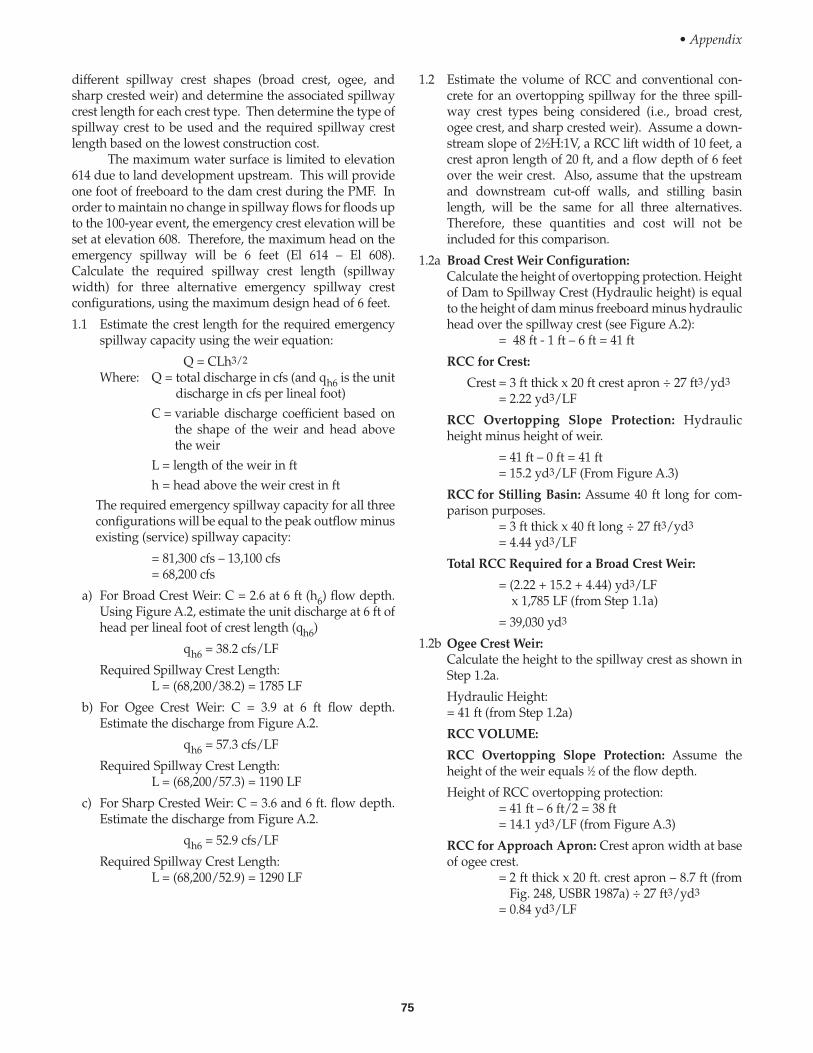
75
1.2 Estimate the volume of RCC and conventional con-crete for an overtopping spillway for the three spill-way crest types being considered (i.e., broad crest,ogee crest, and sharp crested weir). Assume a down-stream slope of 21⁄2H:1V, a RCC lift width of 10 feet, acrest apron length of 20 ft, and a flow depth of 6 feetover the weir crest. Also, assume that the upstreamand downstream cut-off walls, and stilling basinlength, will be the same for all three alternatives.Therefore, these quantities and cost will not beincluded for this comparison.
1.2a Broad Crest Weir Configuration:Calculate the height of overtopping protection. Heightof Dam to Spillway Crest (Hydraulic height) is equalto the height of dam minus freeboard minus hydraulichead over the spillway crest (see Figure A.2):
= 48 ft - 1 ft – 6 ft = 41 ft
RCC for Crest:
Crest = 3 ft thick x 20 ft crest apron ÷ 27 ft3/yd3
= 2.22 yd3/LF
RCC Overtopping Slope Protection: Hydraulicheight minus height of weir.
= 41 ft – 0 ft = 41 ft= 15.2 yd3/LF (From Figure A.3)
RCC for Stilling Basin: Assume 40 ft long for com-parison purposes.
= 3 ft thick x 40 ft long ÷ 27 ft3/yd3
= 4.44 yd3/LF
Total RCC Required for a Broad Crest Weir:
= (2.22 + 15.2 + 4.44) yd3/LFx 1,785 LF (from Step 1.1a)
= 39,030 yd3
1.2b Ogee Crest Weir:Calculate the height to the spillway crest as shown inStep 1.2a.
Hydraulic Height:= 41 ft (from Step 1.2a)
RCC VOLUME:
RCC Overtopping Slope Protection: Assume theheight of the weir equals 1⁄2 of the flow depth.
Height of RCC overtopping protection:= 41 ft – 6 ft/2 = 38 ft= 14.1 yd3/LF (from Figure A.3)
RCC for Approach Apron: Crest apron width at baseof ogee crest.
= 2 ft thick x 20 ft. crest apron – 8.7 ft (fromFig. 248, USBR 1987a) ÷ 27 ft3/yd3
= 0.84 yd3/LF
• Appendix
different spillway crest shapes (broad crest, ogee, andsharp crested weir) and determine the associated spillwaycrest length for each crest type. Then determine the type ofspillway crest to be used and the required spillway crestlength based on the lowest construction cost.
The maximum water surface is limited to elevation614 due to land development upstream. This will provideone foot of freeboard to the dam crest during the PMF. Inorder to maintain no change in spillway flows for floods upto the 100-year event, the emergency crest elevation will beset at elevation 608. Therefore, the maximum head on theemergency spillway will be 6 feet (El 614 – El 608).Calculate the required spillway crest length (spillwaywidth) for three alternative emergency spillway crestconfigurations, using the maximum design head of 6 feet.
1.1 Estimate the crest length for the required emergencyspillway capacity using the weir equation:
Q = CLh3/2
Where: Q = total discharge in cfs (and qh6 is the unitdischarge in cfs per lineal foot)
C = variable discharge coefficient based onthe shape of the weir and head abovethe weir
L = length of the weir in fth = head above the weir crest in ft
The required emergency spillway capacity for all threeconfigurations will be equal to the peak outflow minusexisting (service) spillway capacity:
= 81,300 cfs – 13,100 cfs= 68,200 cfs
a) For Broad Crest Weir: C = 2.6 at 6 ft (h6) flow depth.Using Figure A.2, estimate the unit discharge at 6 ft ofhead per lineal foot of crest length (qh6)
qh6 = 38.2 cfs/LF
Required Spillway Crest Length: L = (68,200/38.2) = 1785 LF
b) For Ogee Crest Weir: C = 3.9 at 6 ft flow depth.Estimate the discharge from Figure A.2.
qh6 = 57.3 cfs/LF
Required Spillway Crest Length: L = (68,200/57.3) = 1190 LF
c) For Sharp Crested Weir: C = 3.6 and 6 ft. flow depth.Estimate the discharge from Figure A.2.
qh6 = 52.9 cfs/LF
Required Spillway Crest Length: L = (68,200/52.9) = 1290 LF
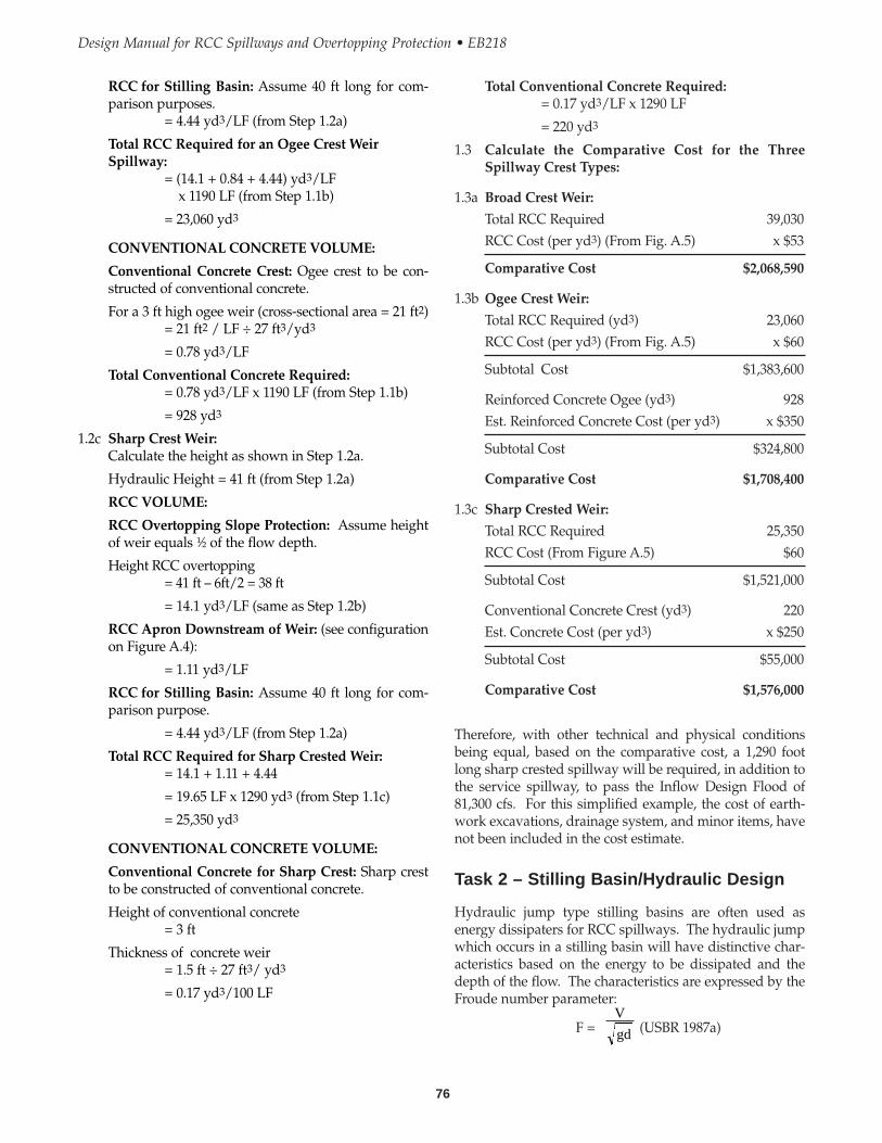
76
Design Manual for RCC Spillways and Overtopping Protection • EB218
Total Conventional Concrete Required:= 0.17 yd3/LF x 1290 LF
= 220 yd3
1.3 Calculate the Comparative Cost for the ThreeSpillway Crest Types:
1.3a Broad Crest Weir:
Total RCC Required 39,030RCC Cost (per yd3) (From Fig. A.5) x $53
Comparative Cost $2,068,590
1.3b Ogee Crest Weir:
Total RCC Required (yd3) 23,060RCC Cost (per yd3) (From Fig. A.5) x $60
Subtotal Cost $1,383,600
Reinforced Concrete Ogee (yd3) 928Est. Reinforced Concrete Cost (per yd3) x $350
Subtotal Cost $324,800
Comparative Cost $1,708,400
1.3c Sharp Crested Weir:
Total RCC Required 25,350RCC Cost (From Figure A.5) $60
Subtotal Cost $1,521,000
Conventional Concrete Crest (yd3) 220Est. Concrete Cost (per yd3) x $250
Subtotal Cost $55,000
Comparative Cost $1,576,000
Therefore, with other technical and physical conditionsbeing equal, based on the comparative cost, a 1,290 footlong sharp crested spillway will be required, in addition tothe service spillway, to pass the Inflow Design Flood of81,300 cfs. For this simplified example, the cost of earth-work excavations, drainage system, and minor items, havenot been included in the cost estimate.
Task 2 – Stilling Basin/Hydraulic Design
Hydraulic jump type stilling basins are often used asenergy dissipaters for RCC spillways. The hydraulic jumpwhich occurs in a stilling basin will have distinctive char-acteristics based on the energy to be dissipated and thedepth of the flow. The characteristics are expressed by theFroude number parameter:
F = (USBR 1987a)V
gd
RCC for Stilling Basin: Assume 40 ft long for com-parison purposes.
= 4.44 yd3/LF (from Step 1.2a)
Total RCC Required for an Ogee Crest WeirSpillway:
= (14.1 + 0.84 + 4.44) yd3/LFx 1190 LF (from Step 1.1b)
= 23,060 yd3
CONVENTIONAL CONCRETE VOLUME:
Conventional Concrete Crest: Ogee crest to be con-structed of conventional concrete.
For a 3 ft high ogee weir (cross-sectional area = 21 ft2)= 21 ft2 / LF ÷ 27 ft3/yd3
= 0.78 yd3/LF
Total Conventional Concrete Required:= 0.78 yd3/LF x 1190 LF (from Step 1.1b)
= 928 yd3
1.2c Sharp Crest Weir:Calculate the height as shown in Step 1.2a.
Hydraulic Height = 41 ft (from Step 1.2a)
RCC VOLUME:
RCC Overtopping Slope Protection: Assume heightof weir equals 1⁄2 of the flow depth.
Height RCC overtopping = 41 ft – 6ft/2 = 38 ft
= 14.1 yd3/LF (same as Step 1.2b)
RCC Apron Downstream of Weir: (see configurationon Figure A.4):
= 1.11 yd3/LF
RCC for Stilling Basin: Assume 40 ft long for com-parison purpose.
= 4.44 yd3/LF (from Step 1.2a)
Total RCC Required for Sharp Crested Weir:= 14.1 + 1.11 + 4.44
= 19.65 LF x 1290 yd3 (from Step 1.1c)
= 25,350 yd3
CONVENTIONAL CONCRETE VOLUME:
Conventional Concrete for Sharp Crest: Sharp crestto be constructed of conventional concrete.
Height of conventional concrete= 3 ft
Thickness of concrete weir= 1.5 ft ÷ 27 ft3/ yd3
= 0.17 yd3/100 LF
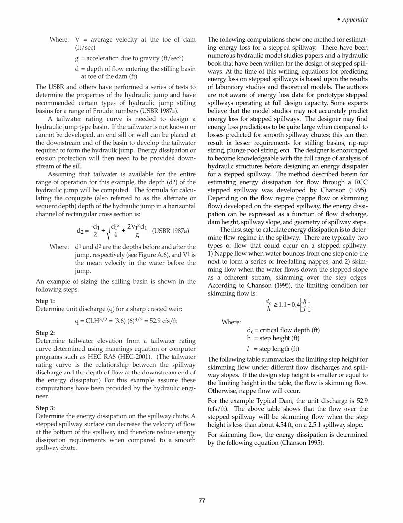
77
Where: V = average velocity at the toe of dam(ft/sec)
g = acceleration due to gravity (ft/sec2)
d = depth of flow entering the stilling basinat toe of the dam (ft)
The USBR and others have performed a series of tests todetermine the properties of the hydraulic jump and haverecommended certain types of hydraulic jump stillingbasins for a range of Froude numbers (USBR 1987a).
A tailwater rating curve is needed to design ahydraulic jump type basin. If the tailwater is not known orcannot be developed, an end sill or wall can be placed atthe downstream end of the basin to develop the tailwaterrequired to form the hydraulic jump. Energy dissipation orerosion protection will then need to be provided down-stream of the sill.
Assuming that tailwater is available for the entirerange of operation for this example, the depth (d2) of thehydraulic jump will be computed. The formula for calcu-lating the conjugate (also referred to as the alternate orsequent depth) depth of the hydraulic jump in a horizontalchannel of rectangular cross section is:
(USBR 1987a)
Where: d1 and d2 are the depths before and after thejump, respectively (see Figure A.6), and V1 isthe mean velocity in the water before thejump.
An example of sizing the stilling basin is shown in thefollowing steps.
Step 1:Determine unit discharge (q) for a sharp crested weir:
q = CLH3/2 = (3.6) (6)3/2 = 52.9 cfs/ft
Step 2:Determine tailwater elevation from a tailwater ratingcurve determined using mannings equation or computerprograms such as HEC RAS (HEC-2001). (The tailwaterrating curve is the relationship between the spillwaydischarge and the depth of flow at the downstream end ofthe energy dissipator.) For this example assume thesecomputations have been provided by the hydraulic engi-neer.
Step 3:Determine the energy dissipation on the spillway chute. Astepped spillway surface can decrease the velocity of flowat the bottom of the spillway and therefore reduce energydissipation requirements when compared to a smoothspillway chute.
d
d V dg2
12 12 14
2=
-d2
1 + +
The following computations show one method for estimat-ing energy loss for a stepped spillway. There have beennumerous hydraulic model studies papers and a hydraulicbook that have been written for the design of stepped spill-ways. At the time of this writing, equations for predictingenergy loss on stepped spillways is based upon the resultsof laboratory studies and theoretical models. The authorsare not aware of energy loss data for prototype steppedspillways operating at full design capacity. Some expertsbelieve that the model studies may not accurately predictenergy loss for stepped spillways. The designer may findenergy loss predictions to be quite large when compared tolosses predicted for smooth spillway chutes; this can thenresult in lesser requirements for stilling basins, rip-rapsizing, plunge pool sizing, etc). The designer is encouragedto become knowledgeable with the full range of analysis ofhydraulic structures before designing an energy dissipaterfor a stepped spillway. The method described herein forestimating energy dissipation for flow through a RCCstepped spillway was developed by Chanson (1995).Depending on the flow regime (nappe flow or skimmingflow) developed on the stepped spillway, the energy dissi-pation can be expressed as a function of flow discharge,dam height, spillway slope, and geometry of spillway steps.
The first step to calculate energy dissipation is to deter-mine flow regime in the spillway. There are typically twotypes of flow that could occur on a stepped spillway:1) Nappe flow when water bounces from one step onto thenext to form a series of free-falling nappes, and 2) skim-ming flow when the water flows down the stepped slopeas a coherent stream, skimming over the step edges.According to Chanson (1995), the limiting condition forskimming flow is:
Where:dc = critical flow depth (ft)h = step height (ft)
l = step length (ft)
The following table summarizes the limiting step height forskimming flow under different flow discharges and spill-way slopes. If the design step height is smaller or equal tothe limiting height in the table, the flow is skimming flow.Otherwise, nappe flow will occur.For the example Typical Dam, the unit discharge is 52.9(cfs/ft). The above table shows that the flow over thestepped spillway will be skimming flow when the stepheight is less than about 4.54 ft, on a 2.5:1 spillway slope.For skimming flow, the energy dissipation is determinedby the following equation (Chanson 1995):
dh
hl
c ≥ −
1 1 0 4. .
• Appendix
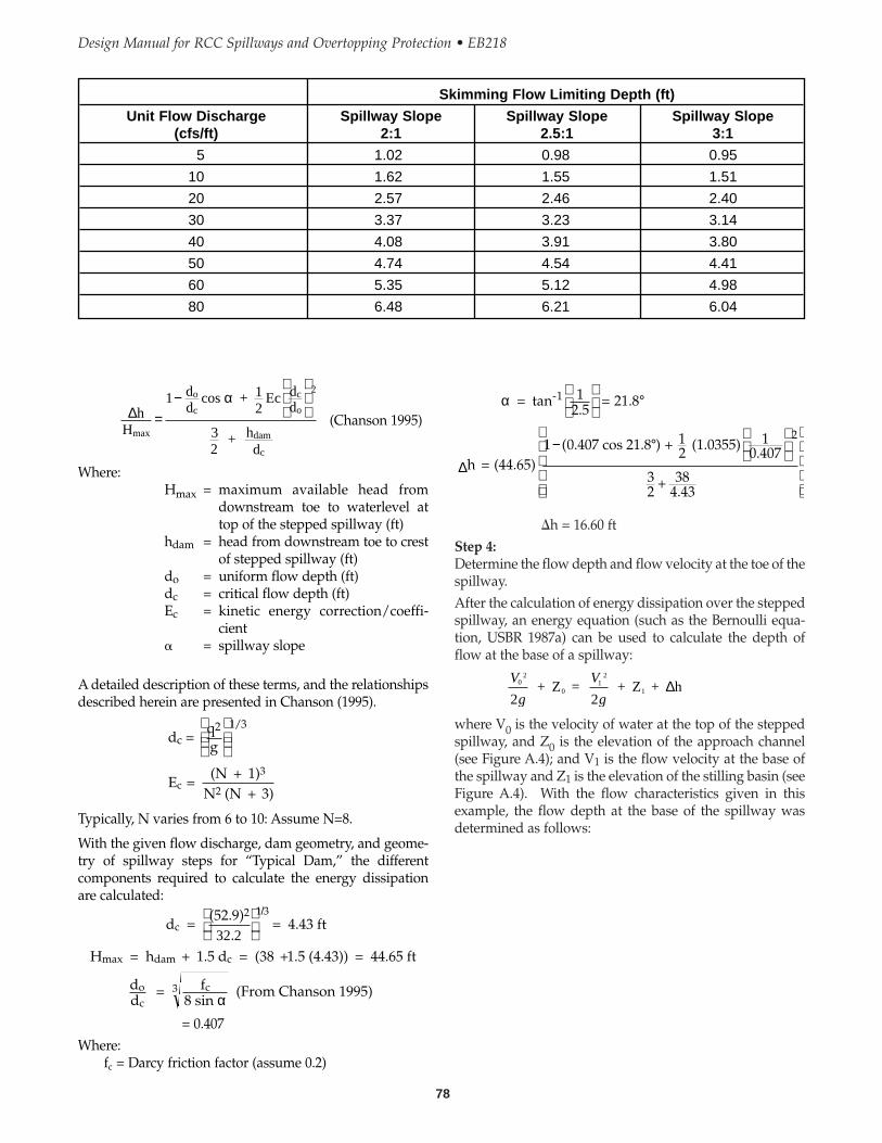
78
Design Manual for RCC Spillways and Overtopping Protection • EB218
�h = 16.60 ftStep 4:Determine the flow depth and flow velocity at the toe of thespillway. After the calculation of energy dissipation over the steppedspillway, an energy equation (such as the Bernoulli equa-tion, USBR 1987a) can be used to calculate the depth offlow at the base of a spillway:
where V0 is the velocity of water at the top of the steppedspillway, and Z0 is the elevation of the approach channel(see Figure A.4); and V1 is the flow velocity at the base ofthe spillway and Z1 is the elevation of the stilling basin (seeFigure A.4). With the flow characteristics given in thisexample, the flow depth at the base of the spillway wasdetermined as follows:
V
g
V
g0
2
01
2
1
2 + Z =
2 + Z + h∆
= tan = 21.8
h = (44.65) 1 0 407 cos 21.8 ) + (1.0355)
+ 384.43
-1
α 12 5
12
10 407
32
2
.
( . .
°
− °
∆
(Chanson 1995)
Where:Hmax = maximum available head from
downstream toe to waterlevel attop of the stepped spillway (ft)
hdam = head from downstream toe to crestof stepped spillway (ft)
do = uniform flow depth (ft)dc = critical flow depth (ft)Ec = kinetic energy correction/coeffi-
cient� = spillway slope
A detailed description of these terms, and the relationshipsdescribed herein are presented in Chanson (1995).
Typically, N varies from 6 to 10: Assume N=8.
With the given flow discharge, dam geometry, and geome-try of spillway steps for “Typical Dam,” the differentcomponents required to calculate the energy dissipationare calculated:
= 0.407Where:
fi = Darcy friction factor (assume 0.2)
d = (52.9)
= 4.43 ft
H = h + 1.5 d = (38 +1.5 (4.43)) = 44.65 ft
dd
= f8 sin
(From Chanson 1995)
c2 1 3
max dam c
oc
c3
32 2.
/
α
E = (N + 1)
N (N + 3)c
3
2
dc = qg2
1 3/
∆h
dd
Ec ddc
c
o
H
cos + 12
+ hd
max
o
dam
c
=−
1
32
2α
Skimming Flow Limiting Depth (ft)
Unit Flow Discharge Spillway Slope Spillway Slope Spillway Slope(cfs/ft) 2:1 2.5:1 3:1
5 1.02 0.98 0.95
10 1.62 1.55 1.51
20 2.57 2.46 2.40
30 3.37 3.23 3.14
40 4.08 3.91 3.80
50 4.74 4.54 4.41
60 5.35 5.12 4.98
80 6.48 6.21 6.04
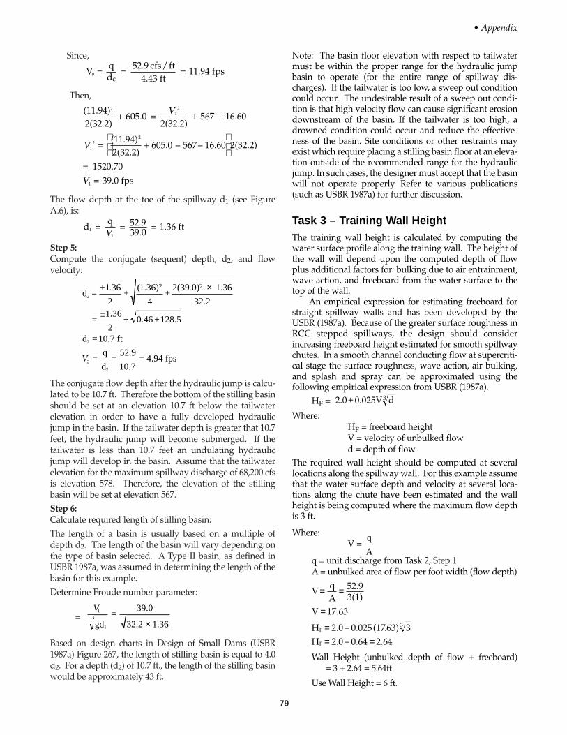
79
Since,
Then,
The flow depth at the toe of the spillway d1 (see FigureA.6), is:
Step 5:Compute the conjugate (sequent) depth, d2, and flowvelocity:
The conjugate flow depth after the hydraulic jump is calcu-lated to be 10.7 ft. Therefore the bottom of the stilling basinshould be set at an elevation 10.7 ft below the tailwaterelevation in order to have a fully developed hydraulicjump in the basin. If the tailwater depth is greater that 10.7feet, the hydraulic jump will become submerged. If thetailwater is less than 10.7 feet an undulating hydraulicjump will develop in the basin. Assume that the tailwaterelevation for the maximum spillway discharge of 68,200 cfsis elevation 578. Therefore, the elevation of the stillingbasin will be set at elevation 567.Step 6:Calculate required length of stilling basin:The length of a basin is usually based on a multiple ofdepth d2. The length of the basin will vary depending onthe type of basin selected. A Type II basin, as defined inUSBR 1987a, was assumed in determining the length of thebasin for this example.Determine Froude number parameter:
=
Based on design charts in Design of Small Dams (USBR1987a) Figure 267, the length of stilling basin is equal to 4.0d2. For a depth (d2) of 10.7 ft., the length of the stilling basinwould be approximately 43 ft.
V1
1gd=
39.0
32.2 1.36×
d =±1 36
2+
1 36
4+
2(39.0) 1.36
32.2
=±1.36
2+ 0.46 +128.5
d =10.7 ft
=q
d=
52.9
10.7= 4.94 fps
2
2
2
2
2 2. ( . ) ×
V
d = = 52.9
39.0 = 1.36 ft11
qV
(11.94)2(32.2)
+ 605.0 = 2(32.2)
+ 567 + 16.60
= (11.94)2(32.2)
+ 605.0 – 567– 16.60 2(32.2)
= 1520.70
= 39.0 fps
21
2
12
2
1
V
V
V
V = qd
= 52.9 cfs/ft
4.43 ft = 11.94 fps0
c
Note: The basin floor elevation with respect to tailwatermust be within the proper range for the hydraulic jumpbasin to operate (for the entire range of spillway dis-charges). If the tailwater is too low, a sweep out conditioncould occur. The undesirable result of a sweep out condi-tion is that high velocity flow can cause significant erosiondownstream of the basin. If the tailwater is too high, adrowned condition could occur and reduce the effective-ness of the basin. Site conditions or other restraints mayexist which require placing a stilling basin floor at an eleva-tion outside of the recommended range for the hydraulicjump. In such cases, the designer must accept that the basinwill not operate properly. Refer to various publications(such as USBR 1987a) for further discussion.
Task 3 – Training Wall HeightThe training wall height is calculated by computing thewater surface profile along the training wall. The height ofthe wall will depend upon the computed depth of flowplus additional factors for: bulking due to air entrainment,wave action, and freeboard from the water surface to thetop of the wall.
An empirical expression for estimating freeboard forstraight spillway walls and has been developed by theUSBR (1987a). Because of the greater surface roughness inRCC stepped spillways, the design should considerincreasing freeboard height estimated for smooth spillwaychutes. In a smooth channel conducting flow at supercriti-cal stage the surface roughness, wave action, air bulking,and splash and spray can be approximated using thefollowing empirical expression from USBR (1987a).
HF =
Where:HF = freeboard heightV = velocity of unbulked flowd = depth of flow
The required wall height should be computed at severallocations along the spillway wall. For this example assumethat the water surface depth and velocity at several loca-tions along the chute have been estimated and the wallheight is being computed where the maximum flow depthis 3 ft.
Where:V =
q = unit discharge from Task 2, Step 1A = unbulked area of flow per foot width (flow depth)
Wall Height (unbulked depth of flow + freeboard) = 3 + 2.64 = 5.64ft
Use Wall Height = 6 ft.
VqA
52.93(1)
V 17.63
H 2.0+ 0.025(17.63) 3H 2.0+ 0.64 2.64
F3
F
= =
=
== =
q
A
2.0 0.025V d+ 3
• Appendix

80
Design Manual for RCC Spillways and Overtopping Protection • EB218
tial of material of the downstream channel. The cut-offwall should extend to competent bedrock or below thedepth of estimated channel degradation or erosion.
The final layout is of the RCC overtopping spillwaysection shown in Figure A.4.
Task 6 – RCC Mix Design
Soil Compaction Method of Mix DesignStep 1.Design Criteria
• RCC overtopping protection is required for an emer-gency spillway in a moderate climate. The RCC will benormally dry.
• The required compressive strength is 3,000 psi at 28days.
• The RCC overtopping protection will be placed in 10-foot wide lifts on the downstream slope of the dam.
• A 1-inch maximum size aggregate (MSA) will be usedto limit segregation during placement.
• Air entraining admixture will not be used. • The project site is in an urban area with existing gravel
pits. • Aggregate quality is to meet ASTM C-39 requirements,
except for gradation changes shown listed below.Step 2.Aggregate is available from a nearby quarry that meets thesuggested RCC aggregate gradation range (as shown onFigure A.7), and conventional concrete aggregate proper-ties. Aggregate properties are:
Task 4 – Check Uplift Pressures
Check the RCC chute and stilling basin slabs for upliftpressure loading.
Unbalanced uplift pressures can exist under the RCCchute and stilling basin slab. These unbalanced pressurescan be caused by an ineffective drainage blanket under theslab or by differential water depth (outside and inside ofthe basin) caused by normal operation of the spillway andstilling basin, Figure A.6.
The RCC chute slab and the basin slab should bechecked for uplift during spillway loading conditions. Aspillway chute floor slab should be designed to withstand aminimum of 5 feet of differential hydrostatic uplift whenconstructed on earth foundations as recommended by theU.S. Army Corps of Engineers (USACE 1990). Hydraulicanalysis for design of the spillway chute and stilling basinmay indicate a larger uplift pressure could occur whichwould then be the basis for the design. Probable upliftforces should be estimated conservatively as their magni-tude is difficult to accurately predict. Even with a gooddrainage system under a slab, the effectiveness at a drainshould be reduced due to the possibility of plugging.
Basin and chute slabs are usually designed to with-stand differential water pressures. During basin operation,water at the inside of the basin can be supercritical andshallow in depth, with high tailwater pressures existingoutside of the walls and beneath the basin floor. Thefollowing computations check the required thickness ofRCC at the base of the sloping chute and at the basin slabfor these loading conditions. For example if the waterdepth outside the basin is 9.0 ft and the depth of flow in thebasin is 2.0 ft, 7.0 ft of net uplift pressure (see Figure A.6)could occur on the slab. The uplift pressure would be thedifferential pressure head times the unit weight of water(7.0 ft)(62.4 lbs/ft) = 437 lbs/ft2. The required thickness ofRCC would then be calculated as follows: Uplift pressuredivided by the average unit weight of RCC.
437 lbs/ft2= 2.91 ft
150 lbs/ft3
Therefore, use a 3-foot thick basin slab.
In general, the recommended minimum RCC slab thick-ness for a stilling basin is typically 3, 1-foot RCC lifts. Thisis generally adequate to resist uplift pressure for differen-tial water pressure up to approximately:
3 ft (150 lbs/ft2) = 7.2 ft of head
62.4 lbs/ft3
Task 5 – Cut-off Wall Design
A cut-off wall is typically constructed at the downstreamend of a stilling basin to control erosion at the downstreamend of the basin slab. Conventional concrete walls areoften constructed for this purpose. The depth of this typeof wall will depend on the erosion and degradation poten-
Aggregate Properties
Property Coarse Fine
Absorption (%) 1.51 1.95
Specific Gravity(saturated surface dry) 2.63 2.85
Step 3.Design RCC mixes at 5 cement contents in about 10 percentincrements
• 320 pcy• 360 pcy• 400 pcy (mid-range "target" cement content, assuming
7.5 psi per pound of cement)• 440 pcy• 480 pcy
Step 4.Conduct modified Proctor compaction test with 400 pcy ofType II, low alkali cement with a specific gravity of 3.15.Since the RCC contains 1-inch maximum size aggregate,ASTM 1557 procedures can be used. The full circular faceshould be used instead of the sector face. If a 2-inch or 11⁄2-inch maximum size aggregate is used, the following
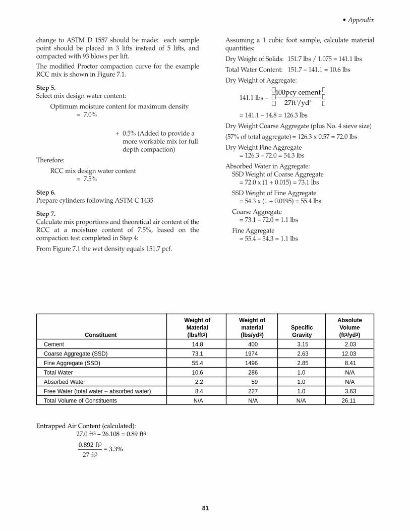
81
change to ASTM D 1557 should be made: each samplepoint should be placed in 3 lifts instead of 5 lifts, andcompacted with 93 blows per lift.The modified Proctor compaction curve for the exampleRCC mix is shown in Figure 7.1.
Step 5.Select mix design water content:
Optimum moisture content for maximum density= 7.0%
+ 0.5% (Added to provide amore workable mix for fulldepth compaction)
Therefore:
RCC mix design water content = 7.5%
Step 6.Prepare cylinders following ASTM C 1435.
Step 7.Calculate mix proportions and theoretical air content of theRCC at a moisture content of 7.5%, based on thecompaction test completed in Step 4:
From Figure 7.1 the wet density equals 151.7 pcf.
Assuming a 1 cubic foot sample, calculate materialquantities:
Dry Weight of Solids: 151.7 lbs / 1.075 = 141.1 lbs
Total Water Content: 151.7 – 141.1 = 10.6 lbs
Dry Weight of Aggregate:
141.1 lbs –
= 141.1 – 14.8 = 126.3 lbs
Dry Weight Coarse Aggregate (plus No. 4 sieve size)
(57% of total aggregate) = 126.3 x 0.57 = 72.0 lbs
Dry Weight Fine Aggregate = 126.3 – 72.0 = 54.3 lbs
Absorbed Water in Aggregate:SSD Weight of Coarse Aggregate
= 72.0 x (1 + 0.015) = 73.1 lbs
SSD Weight of Fine Aggregate= 54.3 x (1 + 0.0195) = 55.4 lbs
Coarse Aggregate= 73.1 – 72.0 = 1.1 lbs
Fine Aggregate= 55.4 – 54.3 = 1.1 lbs
400pcy cement27ft /yd3 3
• Appendix
Weight of Weight of AbsoluteMaterial material Specific Volume
Constituent (lbs/ft3) (lbs/yd3) Gravity (ft3/yd3)
Cement 14.8 400 3.15 2.03
Coarse Aggregate (SSD) 73.1 1974 2.63 12.03
Fine Aggregate (SSD) 55.4 1496 2.85 8.41
Total Water 10.6 286 1.0 N/A
Absorbed Water 2.2 59 1.0 N/A
Free Water (total water – absorbed water) 8.4 227 1.0 3.63
Total Volume of Constituents N/A N/A N/A 26.11
Entrapped Air Content (calculated):27.0 ft3 – 26.108 = 0.89 ft3
0.892 ft
27 ft= 3.3%
3
3
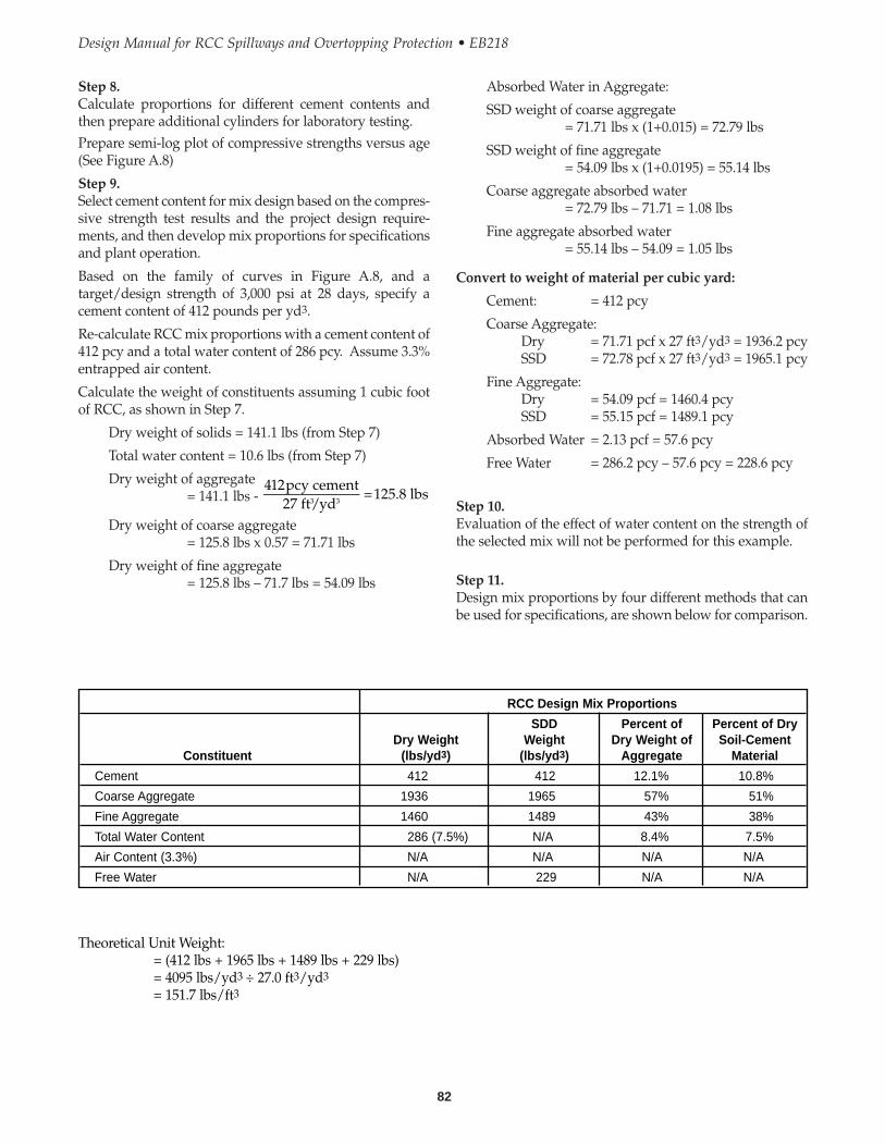
82
Design Manual for RCC Spillways and Overtopping Protection • EB218
Absorbed Water in Aggregate:
SSD weight of coarse aggregate= 71.71 lbs x (1+0.015) = 72.79 lbs
SSD weight of fine aggregate = 54.09 lbs x (1+0.0195) = 55.14 lbs
Coarse aggregate absorbed water = 72.79 lbs – 71.71 = 1.08 lbs
Fine aggregate absorbed water = 55.14 lbs – 54.09 = 1.05 lbs
Convert to weight of material per cubic yard:
Cement: = 412 pcy
Coarse Aggregate:Dry = 71.71 pcf x 27 ft3/yd3 = 1936.2 pcySSD = 72.78 pcf x 27 ft3/yd3 = 1965.1 pcy
Fine Aggregate:Dry = 54.09 pcf = 1460.4 pcySSD = 55.15 pcf = 1489.1 pcy
Absorbed Water = 2.13 pcf = 57.6 pcy
Free Water = 286.2 pcy – 57.6 pcy = 228.6 pcy
Step 10.Evaluation of the effect of water content on the strength ofthe selected mix will not be performed for this example.
Step 11.Design mix proportions by four different methods that canbe used for specifications, are shown below for comparison.
Step 8.Calculate proportions for different cement contents andthen prepare additional cylinders for laboratory testing.Prepare semi-log plot of compressive strengths versus age(See Figure A.8)
Step 9.Select cement content for mix design based on the compres-sive strength test results and the project design require-ments, and then develop mix proportions for specificationsand plant operation.
Based on the family of curves in Figure A.8, and atarget/design strength of 3,000 psi at 28 days, specify acement content of 412 pounds per yd3.
Re-calculate RCC mix proportions with a cement content of412 pcy and a total water content of 286 pcy. Assume 3.3%entrapped air content.
Calculate the weight of constituents assuming 1 cubic footof RCC, as shown in Step 7.
Dry weight of solids = 141.1 lbs (from Step 7)
Total water content = 10.6 lbs (from Step 7)
Dry weight of aggregate= 141.1 lbs -
Dry weight of coarse aggregate= 125.8 lbs x 0.57 = 71.71 lbs
Dry weight of fine aggregate= 125.8 lbs – 71.7 lbs = 54.09 lbs
412pcy cement27 ft/yd
=125.8 lbs3 3
RCC Design Mix Proportions
SDD Percent of Percent of DryDry Weight Weight Dry Weight of Soil-Cement
Constituent (lbs/yd3) (lbs/yd3) Aggregate Material
Cement 412 412 12.1% 10.8%
Coarse Aggregate 1936 1965 57% 51%
Fine Aggregate 1460 1489 43% 38%
Total Water Content 286 (7.5%) N/A 8.4% 7.5%
Air Content (3.3%) N/A N/A N/A N/A
Free Water N/A 229 N/A N/A
Theoretical Unit Weight:= (412 lbs + 1965 lbs + 1489 lbs + 229 lbs)= 4095 lbs/yd3 ÷ 27.0 ft3/yd3
= 151.7 lbs/ft3
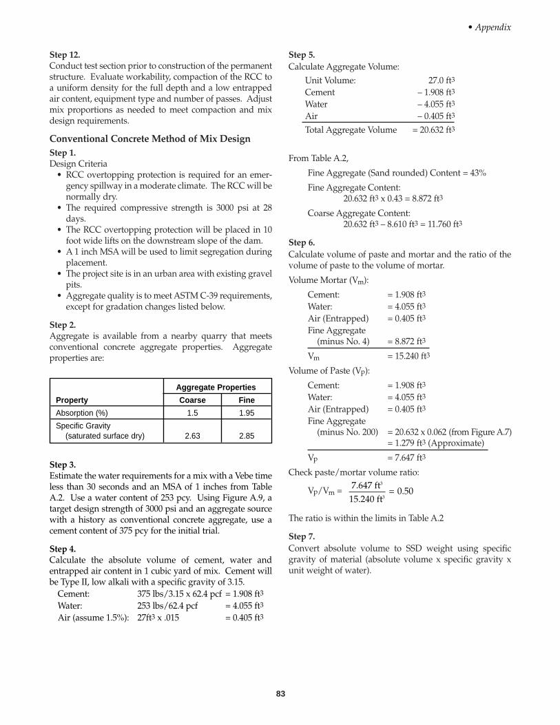
83
Step 12.Conduct test section prior to construction of the permanentstructure. Evaluate workability, compaction of the RCC toa uniform density for the full depth and a low entrappedair content, equipment type and number of passes. Adjustmix proportions as needed to meet compaction and mixdesign requirements.
Conventional Concrete Method of Mix DesignStep 1.Design Criteria
• RCC overtopping protection is required for an emer-gency spillway in a moderate climate. The RCC will benormally dry.
• The required compressive strength is 3000 psi at 28days.
• The RCC overtopping protection will be placed in 10foot wide lifts on the downstream slope of the dam.
• A 1 inch MSA will be used to limit segregation duringplacement.
• The project site is in an urban area with existing gravelpits.
• Aggregate quality is to meet ASTM C-39 requirements,except for gradation changes listed below.
Step 2.Aggregate is available from a nearby quarry that meetsconventional concrete aggregate properties. Aggregateproperties are:
Step 5.Calculate Aggregate Volume:
Unit Volume: 27.0 ft3
Cement – 1.908 ft3
Water – 4.055 ft3
Air – 0.405 ft3
Total Aggregate Volume = 20.632 ft3
From Table A.2,
Fine Aggregate (Sand rounded) Content = 43%
Fine Aggregate Content:20.632 ft3 x 0.43 = 8.872 ft3
Coarse Aggregate Content:20.632 ft3 – 8.610 ft3 = 11.760 ft3
Step 6.Calculate volume of paste and mortar and the ratio of thevolume of paste to the volume of mortar.
Volume Mortar (Vm):
Cement: = 1.908 ft3
Water: = 4.055 ft3
Air (Entrapped) = 0.405 ft3
Fine Aggregate(minus No. 4) = 8.872 ft3
Vm = 15.240 ft3
Volume of Paste (Vp):
Cement: = 1.908 ft3
Water: = 4.055 ft3
Air (Entrapped) = 0.405 ft3
Fine Aggregate(minus No. 200) = 20.632 x 0.062 (from Figure A.7)
= 1.279 ft3 (Approximate)
Vp = 7.647 ft3
Check paste/mortar volume ratio:
Vp/Vm =
The ratio is within the limits in Table A.2
Step 7.Convert absolute volume to SSD weight using specificgravity of material (absolute volume x specific gravity xunit weight of water).
7.647 ft15.240 ft
= 0.503
3
• Appendix
Aggregate Properties
Property Coarse Fine
Absorption (%) 1.5 1.95
Specific Gravity(saturated surface dry) 2.63 2.85
Step 3.Estimate the water requirements for a mix with a Vebe timeless than 30 seconds and an MSA of 1 inches from TableA.2. Use a water content of 253 pcy. Using Figure A.9, atarget design strength of 3000 psi and an aggregate sourcewith a history as conventional concrete aggregate, use acement content of 375 pcy for the initial trial.
Step 4.Calculate the absolute volume of cement, water andentrapped air content in 1 cubic yard of mix. Cement willbe Type II, low alkali with a specific gravity of 3.15.
Cement: 375 lbs/3.15 x 62.4 pcf = 1.908 ft3
Water: 253 lbs/62.4 pcf = 4.055 ft3
Air (assume 1.5%): 27ft3 x .015 = 0.405 ft3

84
Design Manual for RCC Spillways and Overtopping Protection • EB218
Volume of Paste (Vp):
Cement: = 1.908 ft3
Water: = 3.825 ft3
Air (Entrapped) = 0.405 ft3
Fine Aggregate(minus No. 200) = 20.862 x 0.062 (from Figure A.7)
= 1.293 ft3 (Approximate)
Vp = 7.431 ft3
Check paste/mortar volume ratio:
Vp/Vm =
The ratio is within the limits given in Table A.2. Vebe time= 30 seconds. Mixture is well proportioned and workable.Use for trial mix proportions.
Step 9.Prepare cylinders in accordance with ASTM C 1435. RCCmix with 375 pcy cement, resulted in an average lab densityof 153.5 pcf.
Step 10.Re-calculate entrapped air content for molded cylinders.Unit weight of mix: theoretical air free density = 4160.6lbs/(27-0.405) ft3 = 156.4 pcf
Entrapped Air Content =
Step 11.Proportion additional RCC mixes at different cementcontents (in 10 to 15 percent increments), using Vebe test toobtain similar workability. The cement contents shouldbracket the estimated cement content of 375 pcy. In addi-tion, the mix design constituents, including fine and coarseaggregate, need to be adjusted for each cement content byrepeating Steps 4 through 7, assuming an entrapped aircontent of 1.9%.
Step 12.Plot unconfined compressive strength results at the differ-ent cement contents. Based on the family of curves fromFigure A.10, a cement content of 440 pcy should be speci-fied to achieve a design target strength of 3000 psi at 28days. The water content and mixture proportions can thenbe interpolated between the mix designs for the 425 and475 pcy cement mixes.
Step 13.Re-proportion RCC mix constituents with a cement contentof 440 pcy, a water content of 246 pcy, and the calculated aircontent of 1.9%.
156.4 – 153.5156.4
= 1.9%
7.431 ft15.109 ft
= 0.493
3water:cement ratio = 0.67
Theoretical Wet Density (with 1.5% entrapped air content)= 4136 lbs/27 ft3 = 153.2 pcf
Step 8.Prepare trial batch and run Vebe test in accordance with(ASTM C 1170). Test results indicate a Vebe time equal to10 seconds. The mixture is well proportioned but is toowet. Adjust mixing water by 3 percent for each 10 secondchange in Vebe consistency. Calculate new trial mixturewith 6 percent (2 x 3 percent) less moisture
= 253 lbs/(1 + 0.06) = 239 pcy.
Repeat Steps 4 through 8.
Convert absolute volume to weight using the specific grav-ity of the material.
Absolute Specific WeightVolume Gravity (SSD)
Constituent (ft3) (SSD) (lbs)
Cement 1.91 3.15 375
Water (Free) 4.05 1 253
Air (Entrapped) 0.41 N/A 0
Coarse Aggregate 11.76 2.63 1930
Fine Aggregate 8.87 2.85 1578
Total 27.0 ft3 N/A 4136 lbs
Absolute Specific WeightVolume Gravity (SSD)
Constituent (ft3) (SSD) (lbs)
Cement 1.91 3.15 375
Water (Free) 3.82 1 239
Air (Entrapped) 0.41 N/A 0
Coarse Aggregate(SSD) 11.89 2.63 1951
Fine Aggregate(SSD) 8.97 2.85 1595
Total 27.0 ft3 N/A 4161 lbs
water:cement ratio = 0.64
Theoretical Wet Density (with 1.5% air)
Calculate volume of paste and mortar and the ratio of thevolume of paste to the volume of mortar.
Volume Mortar (Vm):
Cement: = 1.908 ft3
Water: = 3.825 ft3
Air (Entrapped) = 0.405 ft3
Fine Aggregate(minus No. 4) = 8.971 ft3
Vm = 15.109 ft3
= 4161 lbs27.0 ft = 154.1pcf3
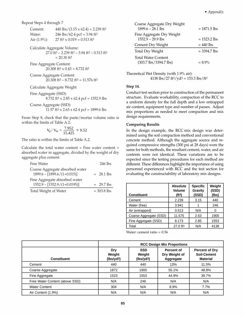
85
Repeat Steps 4 through 7
Cement: 440 lbs/(3.15 x 62.4) = 2.239 ft3
Water: 246 lbs/62.4 pcf = 3.94 ft3
Air (1.9%): 27 ft3 x 0.019 = 0.513 ft3
Calculate Aggregate Volume:27.0 ft3 – 2.239 ft3 – 3.94 ft3 – 0.513 ft3
= 20.30 ft3
Fine Aggregate Content:20.308 ft3 x 0.43 = 8.732 ft3
Coarse Aggregate Content:20.308 ft3 – 8.732 ft3 = 11.576 ft3
Calculate Aggregate Weight
Fine Aggregate (SSD):8.732 ft3 x 2.85 x 62.4 pcf = 1552.9 lbs
Coarse Aggregate (SSD):11.57 ft3 x 2.63 x 62.4 pcf = 1899.6 lbs
From Step 8, check that the paste/mortar volume ratio iswithin the limits of Table A.2:
The ratio is within the limits of Table A.2.
Calculate the total water content = Free water content +absorbed water in aggregate, divided by the weight of dryaggregate plus cement:
Free Water 246 lbsCoarse Aggregate absorbed water
1899.6 – [1899.6/(1+0.015)] = 28.1 lbsFine Aggregate absorbed water
1552.9 – [1552.9/(1+0.0195)] = 29.7 lbs
Total Weight of Water = 303.8 lbs
V / V = 7.95215.425
p m = 0 52.
Coarse Aggregate Dry Weight1899.6 – 28.1 lbs = 1871.5 lbs
Fine Aggregate Dry Weight1552.9 – 29.9 lbs = 1523.2 lbs
Cement Dry Weight = 440 lbs
Total Dry Weight = 3394.7 lbs
Total Water Content(303.7 lbs/3394.7 lbs) = 8.9%
Theoretical Wet Density (with 1.9% air):4138 lbs/27 ft3/yd3 = 153.3 lbs/ft3
Step 14.
Conduct test section prior to construction of the permanentstructure. Evaluate workability, compaction of the RCC toa uniform density for the full depth and a low entrappedair content, equipment type and number of passes. Adjustmix proportions as needed to meet compaction and mixdesign requirements.
Comparing Results
In the design example, the RCC mix design was deter-mined using the soil compaction method and conventionalconcrete method. Although the aggregate source and re-quired compressive strengths (300 psi at 28 days) were thesame for both methods, the resultant cement, water, and aircontents were not identical. These variations are to beexpected since the testing procedures for each method aredifferent. These differences highlight the importance of usingpersonnel experienced with RCC and the test section forevaluating the constructability of laboratory mix designs.
• Appendix
RCC Design Mix Proportions
Dry SSD Percent of Percent of DryWeight Weight Dry Weight of Soil-Cement
Constituent (lbs/yd3) (lbs/yd3) Aggregate Material
Cement 440 440 13% 11.5%
Coarse Aggregate 1872 1900 55.1% 48.8%
Fine Aggregate 1523 1553 44.9% 39.7%
Free Water Content (above SSD) N/A 246 N/A N/A
Water Content 304 N/A 8.9% 7.7%
Air Content (1.9%) N/A N/A N/A N/A
Absolute Specific WeightVolume Gravity (SSD)
Constituent (ft3) (SSD) (lbs)Cement 2.239 3.15 440Water (free) 3.941 1 246Air (entrapped) 0.513 N/A 0Coarse Aggregate (SSD) 11.575 2.63 1900Fine Aggregate (SSD) 8.173 2.85 1553Total 27.0 ft3 N/A 4138
Water: cement ratio = 0.56
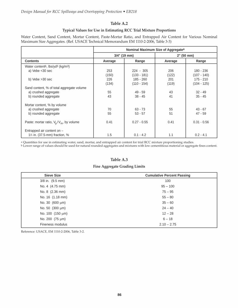
Design Manual for RCC Spillways and Overtopping Protection • EB218
86
Table A.2
Typical Values for Use in Estimating RCC Trial Mixture Proportions
Water Content, Sand Content, Mortar Content, Paste-Mortar Ratio, and Entrapped Air Content for Various NominalMaximum Size Aggregates. (Ref. USACE Technical Memorandum EM 1110-2-2006, Table 3-3)
Nominal Maximum Size of Aggregatea
3/4" (19 mm) 2" (50 mm)
Contents Average Range Average Range
Water contentb, lbs/yd3 (kg/m3)a) Vebe <30 sec 253 224 - 305 206 180 - 236
(150) (133 - 181) (122) (107 - 140)b) Vebe >30 sec 226 185 - 260 201 175 - 210
(134) (110 - 154) (119) (104 - 125)Sand content, % of total aggregate volume
a) crushed aggregate 55 49 - 59 43 32 - 49b) rounded aggregate 43 38 - 45 41 35 - 45
Mortar content, % by volumea) crushed aggregate 70 63 - 73 55 43 - 67b) rounded aggregate 55 53 - 57 51 47 - 59
Paste: mortar ratio, Vp /Vm, by volume 0.41 0.27 - 0.55 0.41 0.31 - 0.56
Entrapped air content on –11⁄2 in. (37.5-mm) fraction, % 1.5 0.1 - 4.2 1.1 0.2 - 4.1
a Quantities for use in estimating water, sand, mortar, and entrapped air content for trial RCC mixture proportioning studies.b Lower range of values should be used for natural rounded aggregates and mixtures with low cementitious material or aggregate fines content.
Table A.3
Fine Aggregate Grading Limits
Sieve Size Cumulative Percent Passing
3/8 in. (9.5 mm) 100
No. 4 (4.75 mm) 95 – 100
No. 8 (2.36 mm) 75 – 95
No. 16 (1.18 mm) 55 – 80
No. 30 (600 µm) 35 – 60
No. 50 (300 µm) 24 – 40
No. 100 (150 µm) 12 – 28
No. 200 (75 µm) 6 – 18
Fineness modulus 2.10 – 2.75
Reference: USACE, EM 1110-2-2006, Table 3-2.

• Appendix
87
Table A.4
Ideal Coarse Aggregate Grading
Cumulative Percent Passing
3 in. to No. 4 2 in. to No. 4 3⁄4 in. to No. 4Sieve Size (4.75 to 75 mm) (4.75 to 50 mm) (4.75 to 19.0 mm)
3 in. (75 mm) 100
21⁄2 in. (63 mm) 88
2 in. (50 mm) 76 100
11⁄2 in. (37.5 mm) 61 81
1 in. (25.0 mm) 44 583⁄4 in. (19.0 mm) 33 44 1001⁄2 in. (12.5 mm) 21 28 633⁄8 in. (9.5 mm) 14 18 41
No. 4 (4.75 mm) — — —
Reference: USACE, EM 1110-2-2006, Table 3-1.
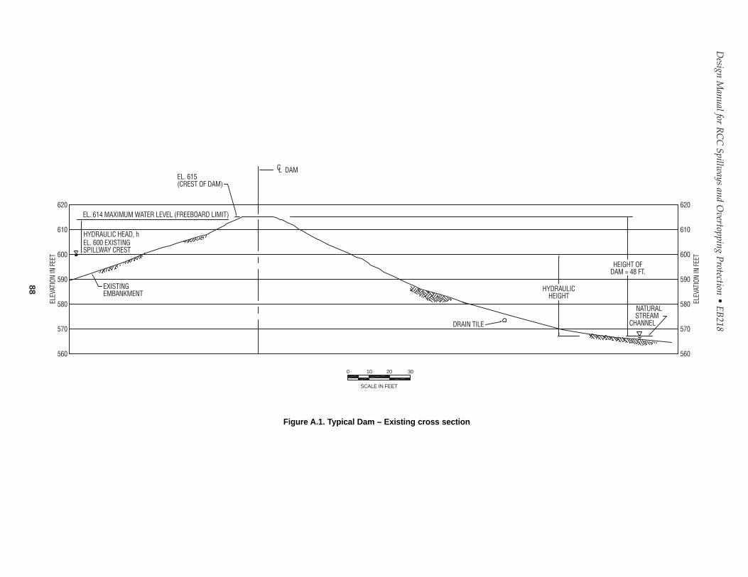
Design M
anual for RC
CSpillw
ays and Overtopping P
rotection• E
B218
88
CL DAMEL. 615(CREST OF DAM)
EL. 614 MAXIMUM WATER LEVEL (FREEBOARD LIMIT)
HYDRAULIC HEAD, hEL. 600 EXISTINGSPILLWAY CREST
EXISTINGEMBANKMENT
ELEV
ATIO
N IN
FEE
T
ELEV
ATIO
N IN
FEE
T
620
610
600
590
580
570
560
DRAIN TILE
HYDRAULICHEIGHT
HEIGHT OFDAM = 48 FT.
NATURALSTREAM
CHANNEL
620
610
600
590
580
570
560
SCALE IN FEET
0 10 20 30
Figure A.1. Typical Dam – Existing cross section
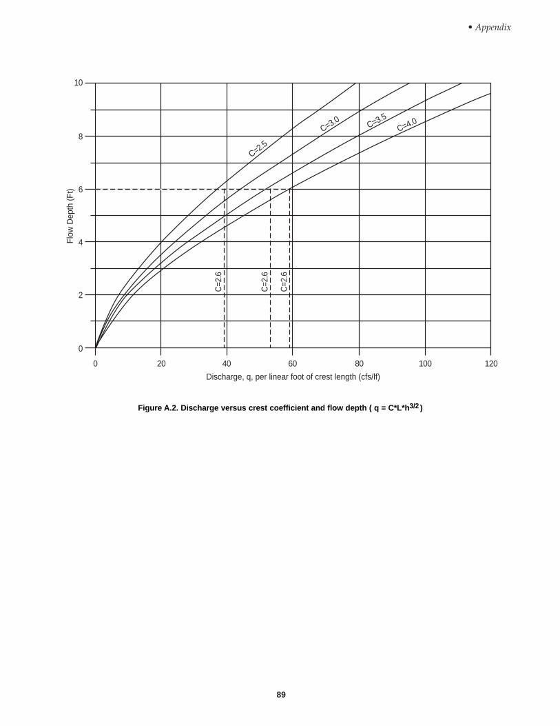
• Appendix
89
C=2.5
C=3.0 C=3.5C=4.0
C=2
.6
C=2
.6
C=2
.6
0 20 40 60 80 100 120
10
8
6
4
2
0
Flow
Dep
th (F
t)
Discharge, q, per linear foot of crest length (cfs/lf)
Figure A.2. Discharge versus crest coefficient and flow depth ( q = C*L*h3/2 )

Design Manual for RCC Spillways and Overtopping Protection • EB218
90
8' widt
h9'
width
10' w
idth
11' w
idth
15.2
14.1
41 feet
38 feet
50
40
30
20
10
0
0 5 10 15 20
RCC Volume (CY)(per linear foot of overtopping width –
for horizontal lifts)
Hei
ght o
f RC
C O
verto
ppin
g (F
t)
Figure A.3. Height of RCC overtopping versus RCC chute volume
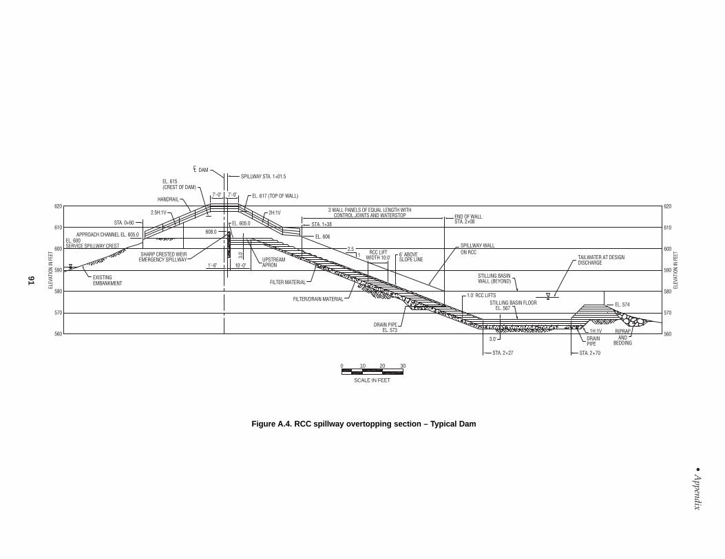
• Appendix
91
SCALE IN FEET
STA. 0+60
APPROACH CHANNEL EL. 605.0EL. 600SERVICE SPILLWAY CREST
EXISTINGEMBANKMENT
CL DAM
EL. 615(CREST OF DAM)
HANDRAIL
SPILLWAY STA. 1+01.5
EL. 617 (TOP OF WALL)7'-0" 7'-0"
2.5H:1V 2H:1V
EL. 605.0
608.0
1'-6" 10'-0"
3.0'
UPSTREAMAPRON
EL. 606
STA. 1+38
FILTER MATERIAL
FILTER/DRAIN MATERIAL
2.51 RCC LIFT
WIDTH 10.0'
3 WALL PANELS OF EQUAL LENGTH WITHCONTROL JOINTS AND WATERSTOP
6' ABOVESLOPE LINE
END OF WALLSTA. 2+08
SPILLWAY WALLON RCC
STILLING BASINWALL (BEYOND)
1.0' RCC LIFTSSTILLING BASIN FLOOR EL. 567
TAILWATER AT DESIGNDISCHARGE
EL. 574
RIPRAPAND
BEDDING
1H:1VDRAINPIPE
STA. 2+70STA. 2+27
3.0'
DRAIN PIPEEL. 573
SHARP CRESTED WEIREMERGENCY SPILLWAY
620
610
600
590
580
570
560
ELEV
ATIO
N IN
FEE
T
620
610
600
590
580
570
560
ELEV
ATIO
N IN
FEE
T
0 10 20 30
Figure A.4. RCC spillway overtopping section – Typical Dam

Design Manual for RCC Spillways and Overtopping Protection • EB218
92
220
200
180
160
140
120
100
80
60
40
20
Cos
t ($/
cubi
c ya
rd)
1,000 10,000 100,000Volume (cubic yards)
Figure A.5. 2001 Cost curve, RCC overtopping protection projects(No adjustments have been made to unit costs based on cementitious content)
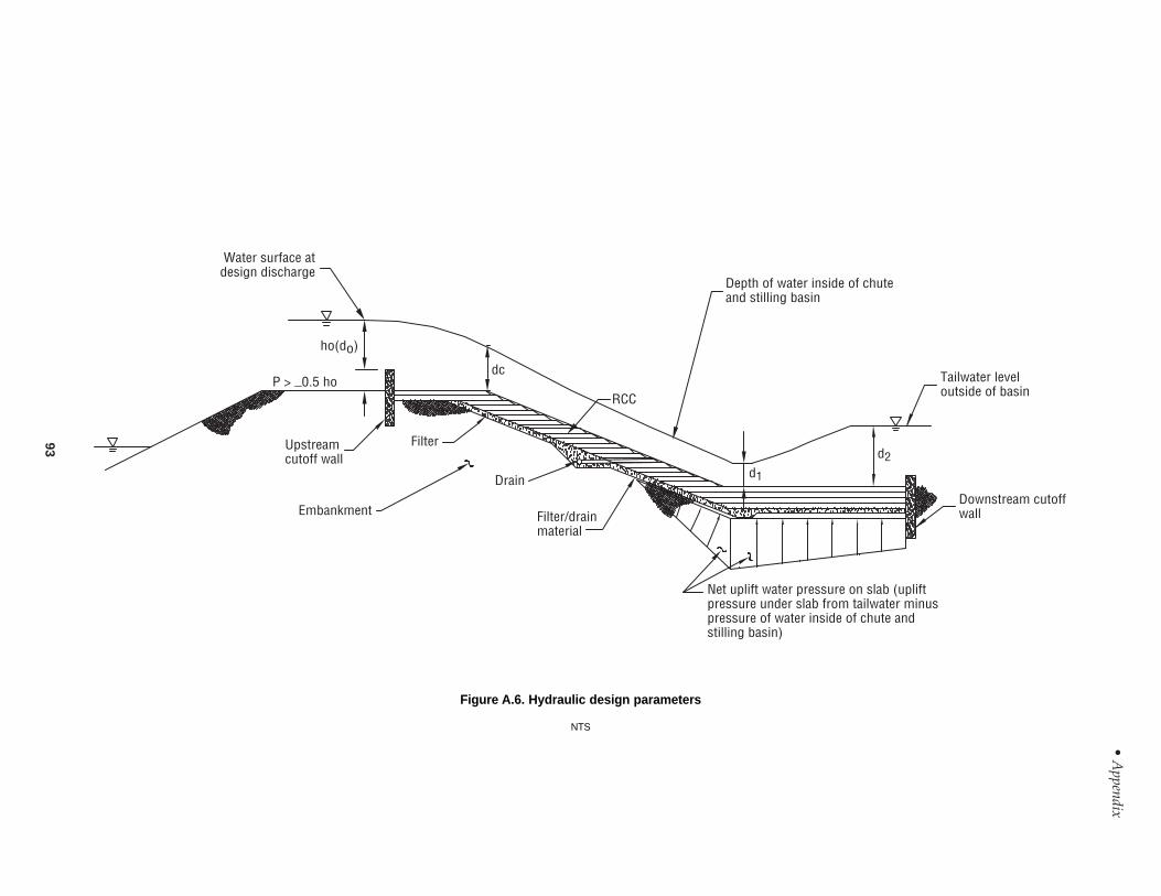
• Appendix
93
Water surface atdesign discharge
ho(do)
P > _0.5 hodc
RCC
Filter/drainmaterial
Depth of water inside of chuteand stilling basin
Tailwater leveloutside of basin
Downstream cutoffwall
Net uplift water pressure on slab (upliftpressure under slab from tailwater minuspressure of water inside of chute andstilling basin)
d1
d2
Drain
Filter
Embankment
Upstreamcutoff wall
Figure A.6. Hydraulic design parameters
NTS
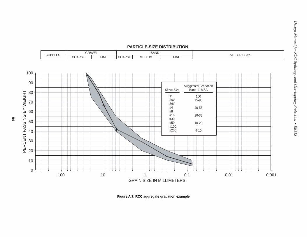
Design M
anual for RC
CSpillw
ays and Overtopping P
rotection• E
B218
94
100
90
80
70
60
50
40
30
20
10
0100 10 1 0.1 0.01 0.001
GRAIN SIZE IN MILLIMETERS
PE
RC
EN
T P
AS
SIN
G B
Y W
EIG
HT
Suggested GradationBand 1" MSA
10075-95
40-55
20-33
10-20
4-10
Sieve Size
1"3/4"3/8"#4#8#16#30#50#100#200
COBBLES SILT OR CLAYGRAVEL SAND
COARSE COARSEFINE MEDIUM FINE
PARTICLE-SIZE DISTRIBUTION
Figure A.7. RCC aggregate gradation example

• Appendix
95
25
20
15
10
5
0
10014 281071Age (days)
4000
3000
2000
1000
0
Com
pres
sive
Str
engt
h (p
si)
Com
pres
sive
Str
engt
h (M
Pa)
480 pcy(285 kg/m3)
440 pcy(261 kg/m3)
400 pcy(237 kg/m3)
360 pcy(214 kg/m3)
320 pcy(190 kg/m3)
(Important note: Information provided in this graph isbased on specific project data. This graph is meant as aproportioning aid for trial batches and should not be reliedupon to accurately estimate results for final mixturedesigns.)
Figure A.8. RCC compressive strength versus age for various cement contents –soil compaction method
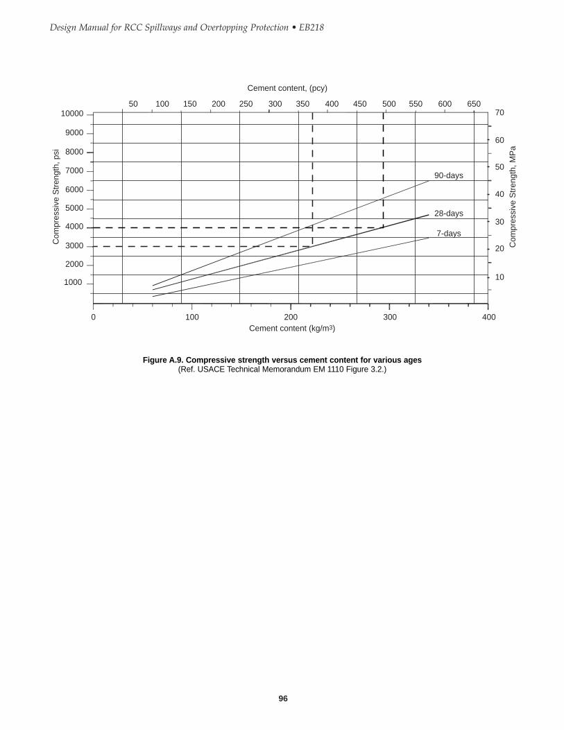
Design Manual for RCC Spillways and Overtopping Protection • EB218
96
Cement content (kg/m3)
70
60
50
40
30
20
10
0 100 200 300 400
10000
9000
8000
6000
5000
4000
3000
2000
1000
7000
Com
pres
sive
Str
engt
h, M
Pa
Com
pres
sive
Str
engt
h, p
si
50 100 150 200 250 300 350 400 450 500 550 600 650
Cement content, (pcy)
90-days
28-days
7-days
Figure A.9. Compressive strength versus cement content for various ages(Ref. USACE Technical Memorandum EM 1110 Figure 3.2.)
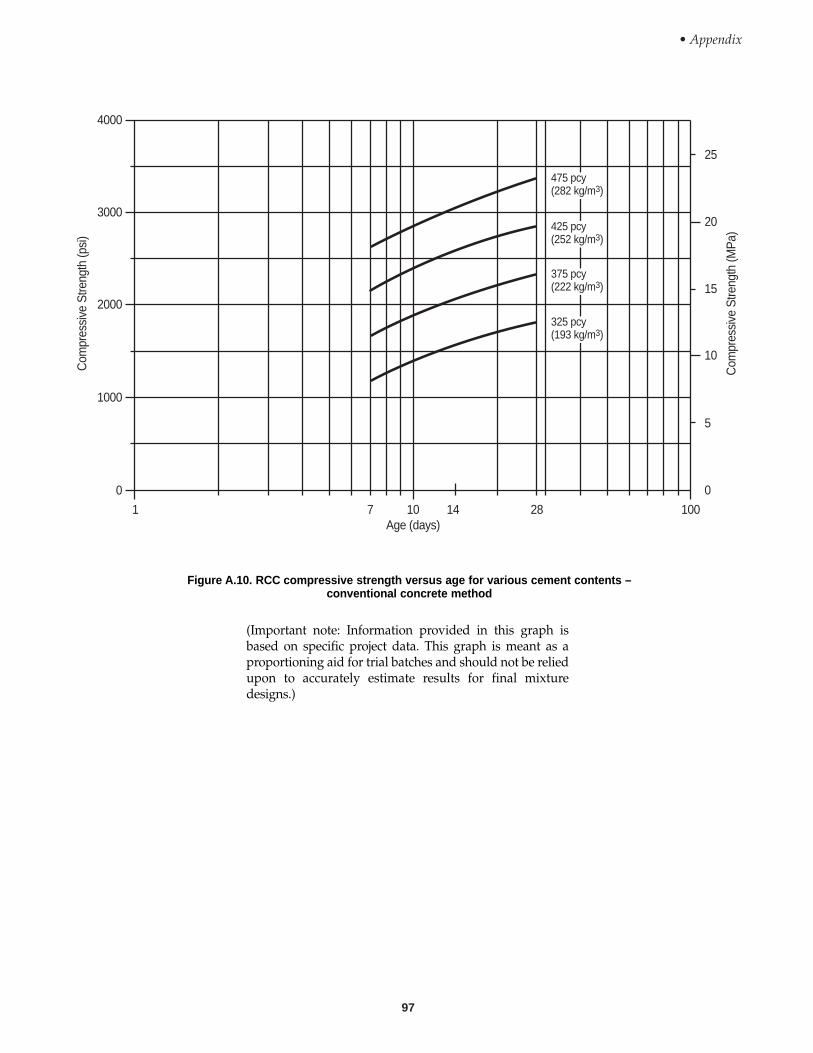
• Appendix
97
475 pcy(282 kg/m3)
425 pcy(252 kg/m3)
375 pcy(222 kg/m3)
325 pcy(193 kg/m3)
25
20
15
10
5
0
Com
pres
sive
Stre
ngth
(MP
a)
Com
pres
sive
Stre
ngth
(psi
)
100281410Age (days)
71
4000
3000
2000
1000
0
(Important note: Information provided in this graph isbased on specific project data. This graph is meant as aproportioning aid for trial batches and should not be reliedupon to accurately estimate results for final mixturedesigns.)
Figure A.10. RCC compressive strength versus age for various cement contents –conventional concrete method

This Guide for RCC Overtopping Protection Design wasdeveloped by Terry Arnold (primary author) Principal,and Sal Todaro, Senior Consultant, URS Corporation.This guide was prepared for the Portland CementAssociation under the supervision of Randall Bass, andWayne Adaska. Contributing authors of various sections of the guide were:John France, Senior Principal; Scott Anderson, SeniorGeotechnical Engineer; Mike Miller, Senior ProjectEngineer; and Frank Lan, Senior Hydraulic Engineer, URSCorporation.
ACKNOWLEDGEMENTS
The authors would like to express their gratitude to: DanJohnson, Senior Principal; Cecil Urlich, Senior Principal;John Sikora, Consultant; Kim Mays, AdministrativeAssistant; and Randy Miller, Designer (URS Corporation),for their invaluable contributions. The Portland CementAssociation express their gratitude to Steve Roberts of theClark County Regional Flood Control District for hiscontribution.
This document is written in English units. To convert tometric units, use the conversion table presented below.
Selected Conversion Factors to SI Units
To Convert Into Multiply by
Square yard (yd2) Square meter (m2) 0.8361
Square foot (ft2) Square meter (m2) 0.0929
Foot (ft) Meter (m) 0.3048
Inch (in.) Millimeter (mm) 25.4
Ton (2000 lb) Kilogram (kg) 907.185
Pound (lb) Kilogram (kg) 0.45359
Pounds per square inch (psi) Kilopascals (kPa) 6.8948
Cubic yard (yd3) Cubic meter (m3) 0.7646
Horsepower (HP) Kilowatt (kW) 0.7457
Fahrenheit (ºF) Celsius (ºC) 5/9 (°F – 32)
Cubic foot (ft3) Liter (L) 28.316
Gallon (U.S.) Liter (L) 3.785
Fluid ounce per pound (fl. oz./lb) Milliliter per kilogram (mL/kg) 65.2

5420 Old Orchard RoadSkokie, Illinois 60077-1083 USA
Phone: 847.966.6200Fax: 847.966.9781Internet: www.portcement.org
An organization of cement companies to improveand extend the uses of portland cement andconcrete through market development, engineering,research, education, and public affairs work.
Printed in U.S.A. EB218

Where:fe = Darcy friction factor (for aerated flow assume 0.2)
Step 4:Determine the flow depth and flow velocity at the toe of thespillway. After the calculation of energy dissipation over the steppedspillway, an energy equation (such as the Bernoulli equa-tion, USBR 1987a) can be used to calculate the depth offlow at the base of a spillway:
where V0 is the velocity of water at the top of the steppedspillway,and Z0 is the elevation of the upstream apron (seeFigure A.4); and V1 is the flow velocity at the base of thespillway, Z1 is the elevation of the stilling basin (see FigureA.4), and d1 is the flow depth before the jump, at the toe ofthe spillway (see Figure A.6). It was assumed that theupstream apron is sufficiently long so that flow over thesharp-crested weir does not affect the development of crit-ical flow at the top of the spillway. With the flow character-istics given in this example, the flow depth at the base ofthe spillway was determined as follows:
Since,
V = qd
= 52.9 cfs/ft
4.43 ft = 11.94 fps0
c
Vg
Vg
02
0 c1
2
1 12 + Z + d =
2 + Z + h + dΔ
Δh = (44.65) 10 407 cos 21.8 )+ (1.03
−°( . 1
2555)
+ 384.43
10 407
32
2
.⎛⎝⎜
⎞⎠⎟
⎡
⎣
⎢⎢⎢⎢
⎤
⎦
⎥⎥⎥⎥
Where:Hmax = maximum available head from
downstream toe to waterlevel attop of the stepped spillway (ft)
hdam = head from downstream toe to crestof stepped spillway (ft)
do = uniform flow depth (ft)dc = critical flow depth (ft)Ec = kinetic energy correction/coeffi-
cientα = spillway slope
A detailed description of these terms, and the relationshipsdescribed herein are presented in Chanson (1995).
Typically, N varies from 6 to 10: Assume N=8.
With the given flow discharge, dam geometry, and geome-try of spillway steps for “Typical Dam,” the different com-ponents required to calculate the energy dissipation are cal-culated:
= 0.407
d =(52.9)
= 4.43 ft
H = h
c2 1 3
max
32 2.
/⎡⎣⎢
⎤⎦⎥
ddam c+ 1.5 d = 38 + 1.5 (4.43) = 44.65 ft
dd
=f
8 sin(From Chansono
c
e3α 1995)
E = (N + 1)
N (N + 3)c
3
2
dc = qg2⎛
⎝⎜⎜
⎞
⎠⎟⎟
1 3/
Δhdd Ec d
dcco
H 1
cos + 12
+ hd
(Chanson 1995)max
o
dam
c
= −
⎛⎝⎜
⎞⎠⎟
⎡
⎣
⎢⎢⎢⎢
⎤
⎦
⎥⎥⎥⎥
α2
32
Skimming Flow Limiting Depth (ft)
Unit Flow Discharge Spillway Slope Spillway Slope Spillway Slope(cfs/ft) 2:1 2.5:1 3:1
5 1.02 0.98 0.95
10 1.62 1.55 1.51
20 2.57 2.46 2.40
30 3.37 3.23 3.14
40 4.08 3.91 3.80
50 4.74 4.54 4.41
60 5.35 5.12 4.98
80 6.48 6.21 6.04
h = 29.13 ftΔ
α = tan-1 1
2 521 8
..⎛
⎝⎜⎞⎠⎟ = °
Design Manual for RCC Spillways and Overtopping Protection • EB218 Revised January 4, 2008
ERRATA
Pages 78 and 79 changes —Values in some of the equations have been adjusted. Also a note has been added in thefirst column on page 79 stating that there is more than one solution to the above equation and only professionalsexperienced in hydraulic analysis should determine which answer should be used for design purposes.
78

Then,
Note: There may be more than one solution to the above equation. Onlyprofessionals experienced in hydraulic analysis should determine whichanswer should be used for design purposes.
The flow depth at the toe of the spillway is:
Step 5:Compute the conjugate (sequent) depth, d2, and flowvelocity:
The conjugate flow depth after the hydraulic jump is calcu-lated to be 9.0 ft. Therefore the bottom of the stilling basinshould be set at an elevation 9.0 ft below the tailwater ele-vation in order to have a fully developed hydraulic jump inthe basin. If the tailwater depth is greater that 9.0 ft, the hydraulic jump will become submerged. If thetailwater is less than 9.0 ft an undulating hydraulic jumpwill develop in the basin. Assume that the tailwater eleva-tion for the maximum spillway discharge of 68,200 cfs iselevation 576. Therefore, the elevation of the stilling basinwill be set at elevation 567.Step 6:Calculate required length of stilling basin:The length of a basin is usually based on a multiple ofdepth d2. The length of the basin will vary depending onthe type of basin selected. A Type II basin, as defined inUSBR 1987a, was assumed in determining the length of thebasin for this example.Determine Froude number parameter:
Based on design charts in Design of Small Dams (USBR1987a) Figure 9-39, the length of stilling basin is equal to 5.75d2. For a depth (d2) of 9.0 ft, the length of the stilling basinwould be approximately 52 ft.
=×
gd
=29.7
32.2 1 .78 = 3.91
1
V
d2
2 21 78
2
1 78
4
2 29 7 1 78
32 2=
−+
( )+
( ) ×
−
. . . .
.
=11 78
20 79 97 5
9 0
52 9
9 05 8
2
22
.. .
.
.
..
+ +
=
= = =
d ft
Vq
d88 fps
d = = 52.9
29.7 = 1.78 ft1
1
qV
(11.94)
2(32.2)+ 605.0+ 4.43 =
2(32.2)+
2
12V
5567 +29.13 +52.9
64.4+
52.9= 15.511
2
V
V
V
1
1
=29.7 fps1V
79
Note: The basin floor elevation with respect to tailwatermust be within the proper range for the hydraulic jumpbasin to operate for the entire range of spillway discharges.If the tailwater is too low, a sweep out condition couldoccur. The undesirable result of a sweep out condition isthat high velocity flow can cause significant erosion down-stream of the basin. If the tailwater is too high, a drownedcondition could occur and reduce the effectiveness of thebasin. Site conditions or other restraints may exist whichrequire placing a stilling basin floor at an elevation outsideof the recommended range for the hydraulic jump. In suchcases, the designer must accept that the basin will not oper-ate properly. Refer to various publications (such as USBR1987a) for further discussion.
Task 3 – Training Wall HeightThe training wall height is calculated by computing thewater surface profile along the training wall. The height ofthe wall will depend upon the computed depth of flowplus additional factors for: bulking due to air entrainment,wave action, and freeboard from the water surface to thetop of the wall.
An empirical expression for estimating freeboard forstraight spillway walls and has been developed by theUSBR (1987a). Because of the greater surface roughness inRCC stepped spillways, the design should considerincreasing freeboard height estimated for smooth spillwaychutes. In a smooth channel conducting flow at supercriti-cal stage the surface roughness, wave action, air bulking,and splash and spray can be approximated using the fol-lowing empirical expression from USBR (1987a).
HF =
Where:HF = freeboard heightV = velocity of unbulked flowd = depth of flow
The required wall height should be computed at severallocations along the spillway wall. For this example assumethat the water surface depth and velocity at several loca-tions along the chute have been estimated and the wallheight is being computed where the maximum flow depthis 3 ft.
Where:V =
q = unit discharge from Task 2, Step 1A = unbulked area of flow per foot width (flow depth)
Wall Height (unbulked depth of flow + freeboard) = 3 + 2.64 = 5.64 ft
Use Wall Height = 6 ft
VqA
52.93(1)
V 17.63
H 2.0 + 0.025 (17.63) 3
H 2.0 + 0.64 2.64
F
F
3
= =
=
=
= =
q
A
2.0 0.025V d+ 3
• Appendix

Design Manual for RCC Spillways and Overtopping Protection • EB218 Revised May 26, 2004
CLARIFICATION
Page 34, Figure 6.13 changes —The thickness derived from the figure in the publication is for unformedsloping RCC steps. The figure below is an addendum to the current figure and includes thegraphic representation and equation for determining the thickness (d) of the RCC step normal to the embankment slope for both formed and unformed RCC steps.
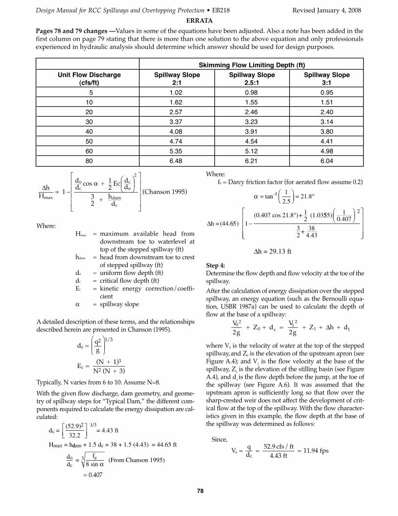
Where:fe = Darcy friction factor (for aerated flow assume 0.2)
Step 4:Determine the flow depth and flow velocity at the toe of thespillway. After the calculation of energy dissipation over the steppedspillway, an energy equation (such as the Bernoulli equa-tion, USBR 1987a) can be used to calculate the depth offlow at the base of a spillway:
where V0 is the velocity of water at the top of the steppedspillway,and Z0 is the elevation of the upstream apron (seeFigure A.4); and V1 is the flow velocity at the base of thespillway, Z1 is the elevation of the stilling basin (see FigureA.4), and d1 is the flow depth before the jump, at the toe ofthe spillway (see Figure A.6). It was assumed that theupstream apron is sufficiently long so that flow over thesharp-crested weir does not affect the development of crit-ical flow at the top of the spillway. With the flow character-istics given in this example, the flow depth at the base ofthe spillway was determined as follows:
Since,
V = qd
= 52.9 cfs/ft
4.43 ft = 11.94 fps0
c
Vg
Vg
02
0 c1
2
1 12 + Z + d =
2 + Z + h + dΔ
Δh = (44.65) 10 407 cos 21.8 )+ (1.03
−°( . 1
2555)
+ 384.43
10 407
32
2
.⎛⎝⎜
⎞⎠⎟
⎡
⎣
⎢⎢⎢⎢
⎤
⎦
⎥⎥⎥⎥
Where:Hmax = maximum available head from
downstream toe to waterlevel attop of the stepped spillway (ft)
hdam = head from downstream toe to crestof stepped spillway (ft)
do = uniform flow depth (ft)dc = critical flow depth (ft)Ec = kinetic energy correction/coeffi-
cientα = spillway slope
A detailed description of these terms, and the relationshipsdescribed herein are presented in Chanson (1995).
Typically, N varies from 6 to 10: Assume N=8.
With the given flow discharge, dam geometry, and geome-try of spillway steps for “Typical Dam,” the different com-ponents required to calculate the energy dissipation are cal-culated:
= 0.407
d =(52.9)
= 4.43 ft
H = h
c2 1 3
max
32 2.
/⎡⎣⎢
⎤⎦⎥
ddam c+ 1.5 d = 38 + 1.5 (4.43) = 44.65 ft
dd
=f
8 sin(From Chansono
c
e3α 1995)
E = (N + 1)
N (N + 3)c
3
2
dc = qg2⎛
⎝⎜⎜
⎞
⎠⎟⎟
1 3/
Δhdd Ec d
dcco
H 1
cos + 12
+ hd
(Chanson 1995)max
o
dam
c
= −
⎛⎝⎜
⎞⎠⎟
⎡
⎣
⎢⎢⎢⎢
⎤
⎦
⎥⎥⎥⎥
α2
32
Skimming Flow Limiting Depth (ft)
Unit Flow Discharge Spillway Slope Spillway Slope Spillway Slope(cfs/ft) 2:1 2.5:1 3:1
5 1.02 0.98 0.95
10 1.62 1.55 1.51
20 2.57 2.46 2.40
30 3.37 3.23 3.14
40 4.08 3.91 3.80
50 4.74 4.54 4.41
60 5.35 5.12 4.98
80 6.48 6.21 6.04
h = 29.13 ftΔ
α = tan-1 1
2 521 8
..⎛
⎝⎜⎞⎠⎟ = °
Design Manual for RCC Spillways and Overtopping Protection • EB218 Revised January 4, 2008
ERRATA
Pages 78 and 79 changes —Values in some of the equations have been adjusted. Also a note has been added in thefirst column on page 79 stating that there is more than one solution to the above equation and only professionalsexperienced in hydraulic analysis should determine which answer should be used for design purposes.
78
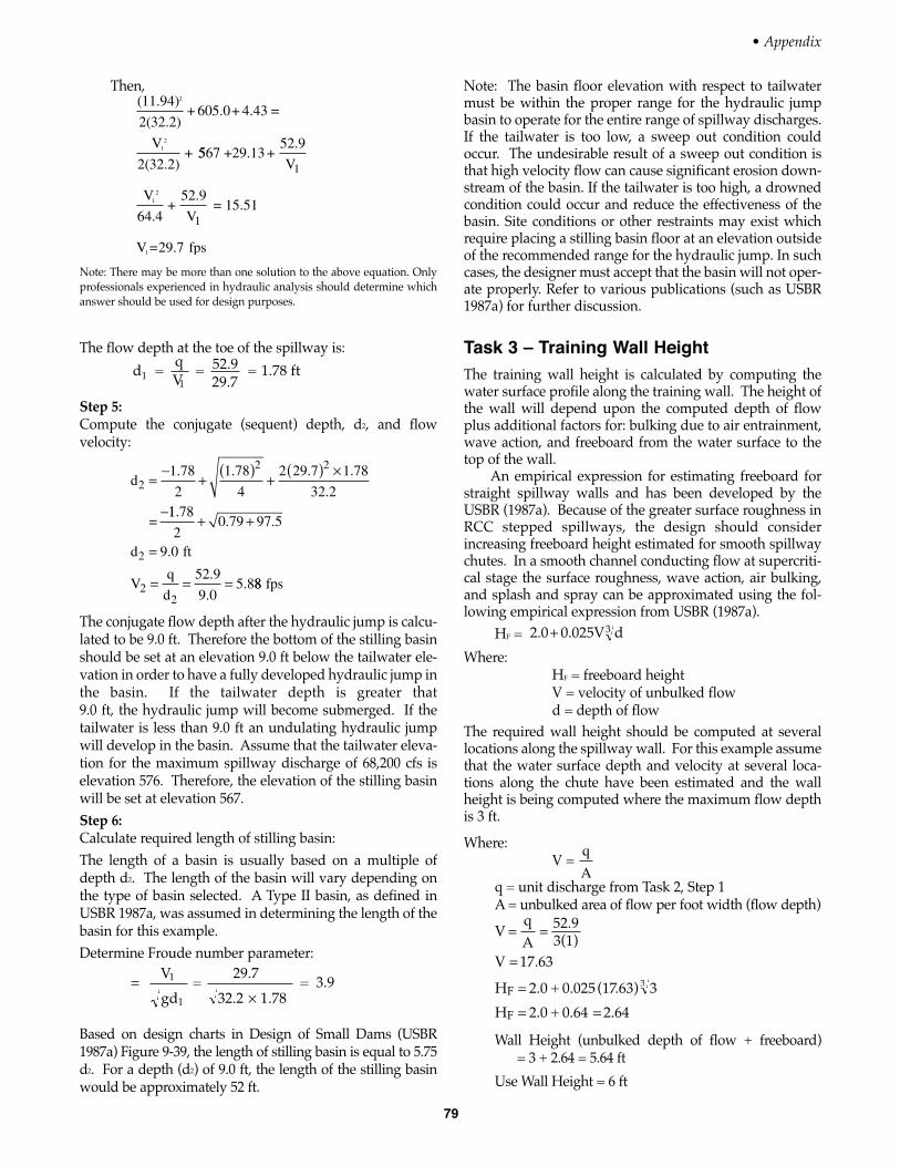
Then,
Note: There may be more than one solution to the above equation. Onlyprofessionals experienced in hydraulic analysis should determine whichanswer should be used for design purposes.
The flow depth at the toe of the spillway is:
Step 5:Compute the conjugate (sequent) depth, d2, and flowvelocity:
The conjugate flow depth after the hydraulic jump is calcu-lated to be 9.0 ft. Therefore the bottom of the stilling basinshould be set at an elevation 9.0 ft below the tailwater ele-vation in order to have a fully developed hydraulic jump inthe basin. If the tailwater depth is greater that 9.0 ft, the hydraulic jump will become submerged. If thetailwater is less than 9.0 ft an undulating hydraulic jumpwill develop in the basin. Assume that the tailwater eleva-tion for the maximum spillway discharge of 68,200 cfs iselevation 576. Therefore, the elevation of the stilling basinwill be set at elevation 567.Step 6:Calculate required length of stilling basin:The length of a basin is usually based on a multiple ofdepth d2. The length of the basin will vary depending onthe type of basin selected. A Type II basin, as defined inUSBR 1987a, was assumed in determining the length of thebasin for this example.Determine Froude number parameter:
Based on design charts in Design of Small Dams (USBR1987a) Figure 9-39, the length of stilling basin is equal to 5.75d2. For a depth (d2) of 9.0 ft, the length of the stilling basinwould be approximately 52 ft.
=×
gd
=29.7
32.2 1 .78 = 3.91
1
V
d2
2 21 78
2
1 78
4
2 29 7 1 78
32 2=
−+
( )+
( ) ×
−
. . . .
.
=11 78
20 79 97 5
9 0
52 9
9 05 8
2
22
.. .
.
.
..
+ +
=
= = =
d ft
Vq
d88 fps
d = = 52.9
29.7 = 1.78 ft1
1
qV
(11.94)
2(32.2)+ 605.0+ 4.43 =
2(32.2)+
2
12V
5567 +29.13 +52.9
64.4+
52.9= 15.511
2
V
V
V
1
1
=29.7 fps1V
79
Note: The basin floor elevation with respect to tailwatermust be within the proper range for the hydraulic jumpbasin to operate for the entire range of spillway discharges.If the tailwater is too low, a sweep out condition couldoccur. The undesirable result of a sweep out condition isthat high velocity flow can cause significant erosion down-stream of the basin. If the tailwater is too high, a drownedcondition could occur and reduce the effectiveness of thebasin. Site conditions or other restraints may exist whichrequire placing a stilling basin floor at an elevation outsideof the recommended range for the hydraulic jump. In suchcases, the designer must accept that the basin will not oper-ate properly. Refer to various publications (such as USBR1987a) for further discussion.
Task 3 – Training Wall HeightThe training wall height is calculated by computing thewater surface profile along the training wall. The height ofthe wall will depend upon the computed depth of flowplus additional factors for: bulking due to air entrainment,wave action, and freeboard from the water surface to thetop of the wall.
An empirical expression for estimating freeboard forstraight spillway walls and has been developed by theUSBR (1987a). Because of the greater surface roughness inRCC stepped spillways, the design should considerincreasing freeboard height estimated for smooth spillwaychutes. In a smooth channel conducting flow at supercriti-cal stage the surface roughness, wave action, air bulking,and splash and spray can be approximated using the fol-lowing empirical expression from USBR (1987a).
HF =
Where:HF = freeboard heightV = velocity of unbulked flowd = depth of flow
The required wall height should be computed at severallocations along the spillway wall. For this example assumethat the water surface depth and velocity at several loca-tions along the chute have been estimated and the wallheight is being computed where the maximum flow depthis 3 ft.
Where:V =
q = unit discharge from Task 2, Step 1A = unbulked area of flow per foot width (flow depth)
Wall Height (unbulked depth of flow + freeboard) = 3 + 2.64 = 5.64 ft
Use Wall Height = 6 ft
VqA
52.93(1)
V 17.63
H 2.0 + 0.025 (17.63) 3
H 2.0 + 0.64 2.64
F
F
3
= =
=
=
= =
q
A
2.0 0.025V d+ 3
• Appendix
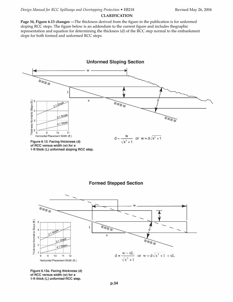
Design Manual for RCC Spillways and Overtopping Protection • EB218 Revised May 26, 2004
CLARIFICATION
Page 34, Figure 6.13 changes —The thickness derived from the figure in the publication is for unformedsloping RCC steps. The figure below is an addendum to the current figure and includes thegraphic representation and equation for determining the thickness (d) of the RCC step normal to the embankment slope for both formed and unformed RCC steps.