Embed Size (px)
Citation preview
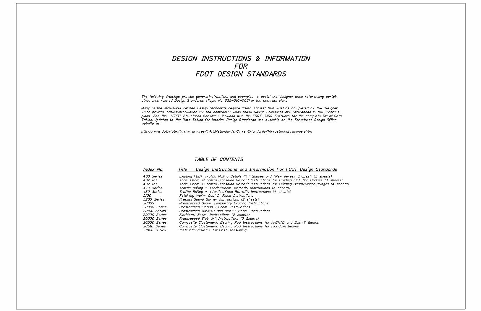
DESIGN INSTRUCTIONS & INFORMATION
FOR
FDOT DESIGN STANDARDS
TABLE OF CONTENTS
Index No. Title - Design Instructions and Information For FDOT Design Standards
The following drawings provide general instructions and examples to assist the designer when referencing certain
structures related Design Standards (Topic No. 625-010-003) in the contract plans.
Many of the structures related Design Standards require "Data Tables" that must be completed by the designer,
which provide critical information for the contractor when these Design Standards are referenced in the contract
plans. See the "FDOT Structures Bar Menu" included with the FDOT CADD Software for the complete list of Data
Tables. Updates to the Data Tables for Interim Design Standards are available on the Structures Design Office
website at:
http://www.dot.state.fl.us/structures/CADD/standards/CurrentStandards/MicrostationDrawings.shtm
400 Series
402 (a)
402 (b)
470 Series
480 Series
5100
5200 Series
20005
20000 Series
20100 Series
20200 Series
20300 Series
20500 Series
20510 Series
21800 Series
Existing FDOT Traffic Railing Details ("F" Shapes and "New Jersey Shapes") (3 sheets)
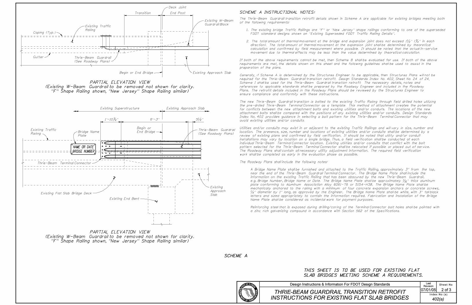
Thrie-Beam Guardrail Transition Retrofit Instructions for Existing Flat Slab Bridges (3 sheets)
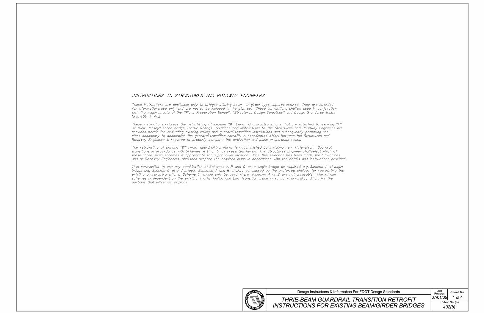
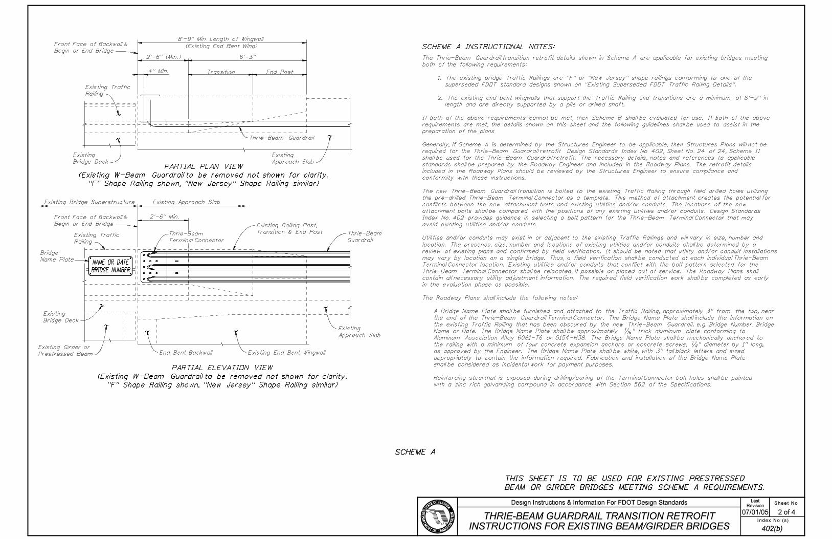
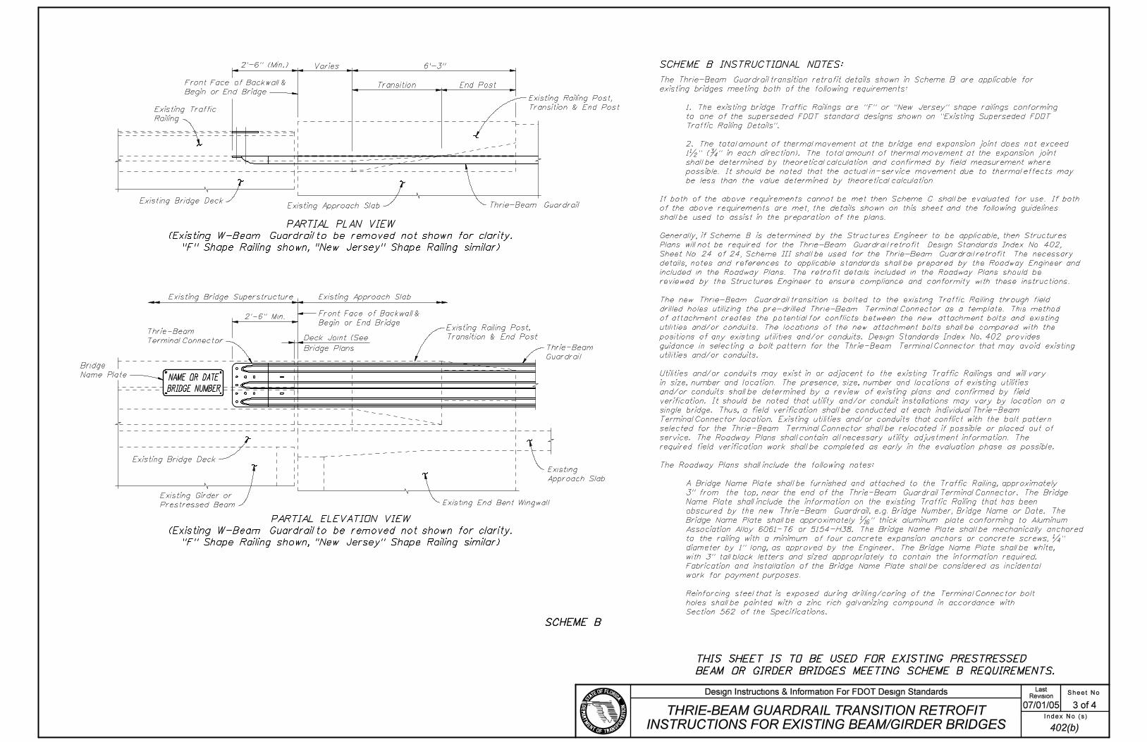
Thrie-Beam Guardrail Transition Retrofit Instructions for Existing Beam/Girder Bridges (4 sheets)
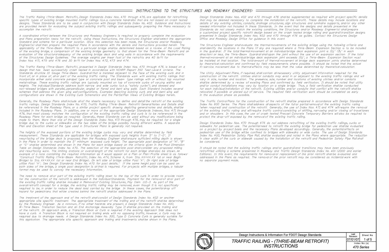
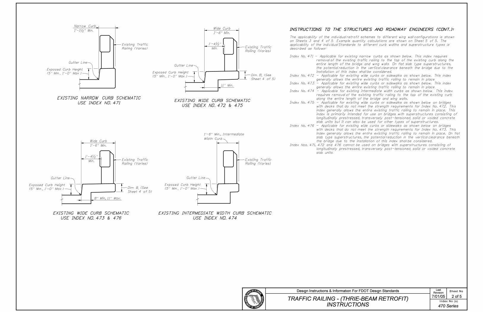
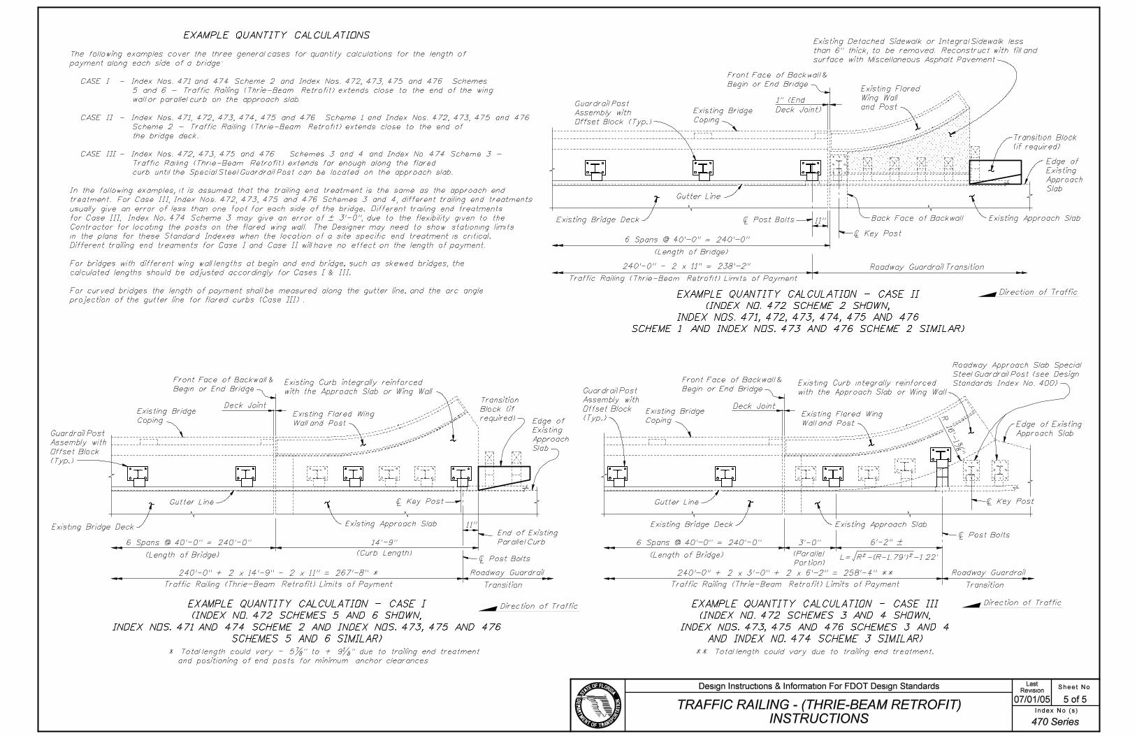
Traffic Railing - (Thrie-Beam Retrofit) Instructions (5 sheets)
Traffic Railing - (Vertical Face Retrofit) Instructions (4 sheets)
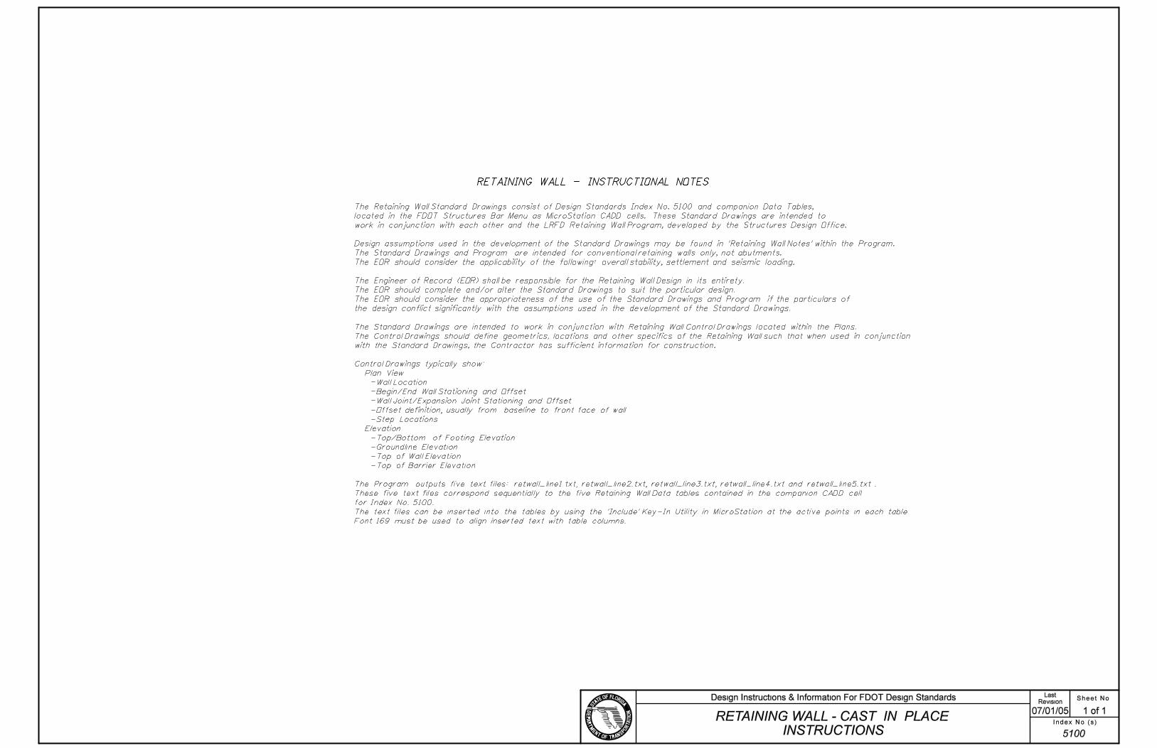
Retaining Wall - Cast In Place Instructions
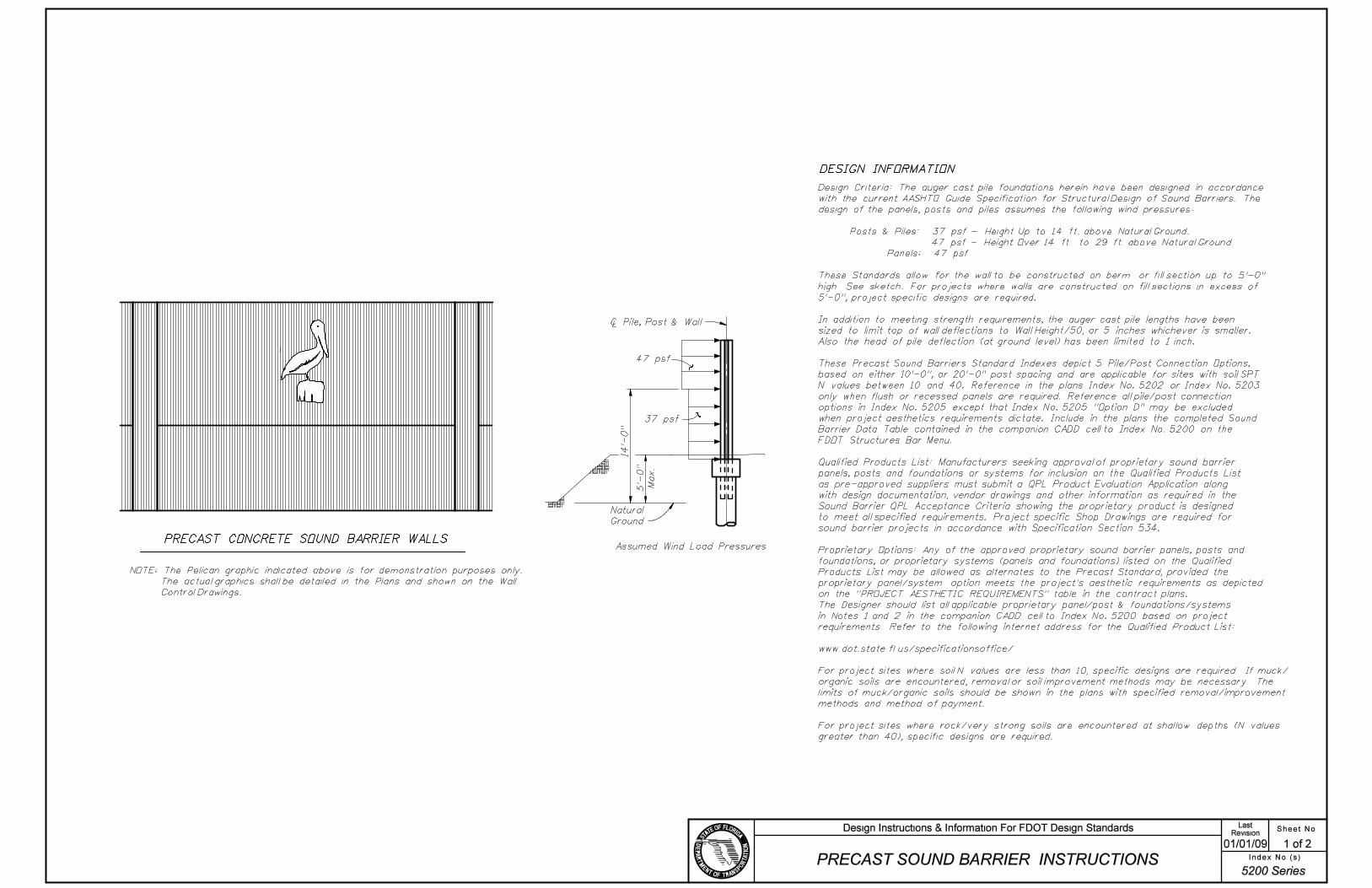
Precast Sound Barrier Instructions (2 sheets)
Prestressed Beam Temporary Bracing Instructions
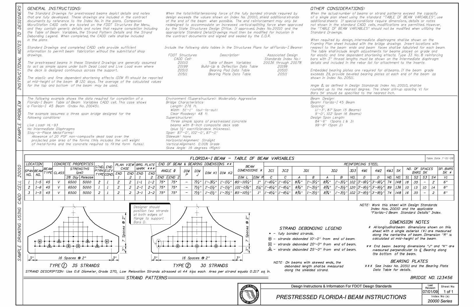
Prestressed Florida-I Beam Instructions
Prestressed AASHTO and Bulb-T Beam Instructions
Florida-U Beam Instructions (2 sheets)
Prestressed Slab Unit Instructions (3 Sheets)
Composite Elastomeric Bearing Pad Instructions for AASHTO and Bulb-T Beams
Composite Elastomeric Bearing Pad Instructions for Florida-I Beams
Instructional Notes for Post-Tensioning

Sheet No.Revision
07/01/05 1 of 3
Last
Index No.(s)
Design Instructions & Information For FDOT Design Standards

Sheet No.Revision
07/01/05 2 of 3
Last
Index No.(s)
Design Instructions & Information For FDOT Design Standards

Sheet No.Revision
07/01/05 3 of 3
Last
Index No.(s)
Design Instructions & Information For FDOT Design Standards

Sheet No.Revision
07/01/05 1 of 3
Last
Index No.(s)
Design Instructions & Information For FDOT Design Standards
Sheet No.Revision
07/01/05 2 of 3
Last
Index No.(s)
Design Instructions & Information For FDOT Design Standards

Sheet No.Revision
07/01/05 3 of 3
Last
Index No.(s)
Design Instructions & Information For FDOT Design Standards
Sheet No.Revision
07/01/05 1 of 4
Last
Index No.(s)
Design Instructions & Information For FDOT Design Standards
Sheet No.Revision
07/01/05 2 of 4
Last
Index No.(s)
Design Instructions & Information For FDOT Design Standards
Sheet No.Revision
07/01/05 3 of 4
Last
Index No.(s)
Design Instructions & Information For FDOT Design Standards

Sheet No.Revision
07/01/05 4 of 4
Last
Index No.(s)
Design Instructions & Information For FDOT Design Standards
Sheet No.Revision
07/01/07 1 of 5
Last
Index No.(s)
Design Instructions & Information For FDOT Design Standards
Sheet No.Revision
7/01/05 2 of 5
Last
Index No.(s)
Design Instructions & Information For FDOT Design Standards

Sheet No.Revision
07/01/05 3 of 5
Last
Index No.(s)
Design Instructions & Information For FDOT Design Standards

Sheet No.Revision
07/01/05 4 of 5
Last
Index No.(s)
Design Instructions & Information For FDOT Design Standards
Sheet No.Revision
07/01/05 5 of 5
Last
Index No.(s)
Design Instructions & Information For FDOT Design Standards

Sheet No.Revision
07/01/07 1 of 4
Last
Index No.(s)
Design Instructions & Information For FDOT Design Standards

Sheet No.Revision
07/01/05 2 of 4
Last
Index No.(s)
Design Instructions & Information For FDOT Design Standards

Sheet No.Revision
07/01/05 3 of 4
Last
Index No.(s)
Design Instructions & Information For FDOT Design Standards

Sheet No.Revision
07/01/05 4 of 4
Last
Index No.(s)
Design Instructions & Information For FDOT Design Standards
Sheet No.Revision
07/01/05 1 of 1
Last
Index No.(s)
Design Instructions & Information For FDOT Design Standards
Sheet No.Revision
01/01/09 1 of 2
Last
Index No.(s)
Design Instructions & Information For FDOT Design Standards

Sheet No.Revision
01/01/09 2 of 2
Last
Index No.(s)
Design Instructions & Information For FDOT Design Standards
SPAN
NO.
TABLE OF TEMPORARY BRACING VARIABLES
TOTAL
NUMBER
OF
BRACES
BL ,
MAXIMUM
UNBRACED
LENGTH (FT)
1
2
3
60.67
60.67
60.67
NO
NO
NO
24
24
24
27.31
27.31
27.31
OVERTURNING
FORCE AT EACH BEAM
END AND ANCHOR
BRACE (KIPxFT)
HORIZONTAL FORCE
AT EACH BEAM
END AND ANCHOR
BRACE (KIP)
TABLE OF WIND LOAD VARIABLES
WIND SPEED, BASIC (MPH)
WIND SPEED, CONSTRUCTION INACTIVE (MPH)
WIND SPEED, CONSTRUCTION ACTIVE (MPH)
GUST EFFECT FACTOR
150
0.85
90
20
DECK WEIGHT (PSF)
20
20
TABLE OF ASSUMED CONSTRUCTION
LOADS (UNFACTORED)
BUILD-UP (PLF)
FORM WEIGHT (PSF)
FINISHING MACHINE TOTAL WEIGHT (KIP)
FINISHING MACHINE WHEEL LOCATION
BEYOND EDGE OF DECK OVERHANG (IN.)
LIVE LOAD (PSF)
LIVE LOAD AT EXTREME DECK EDGE (PLF)
50
113.3
20
75
8.69
8.69
8.69
23.90
23.90
23.90
63.75
63.75
63.75
VELOCITY PRESSURE EXPOSURE COEFFICIENT 1.137
2�
HORIZONTAL
FORCE AT EACH
INTERMEDIATE SPAN
BRACE (KIP)
OVERTURNING
FORCE AT EACH
INTERMEDIATE SPAN
BRACE (KIPxFT)
BRACE ENDS
PRIOR
TO CRANE
RELEASE?
GENERAL INSTRUCTIONS:
IN
ST
RU
CTIO
NA
L
NO
TE
S
TO
DE
SIG
NE
RS
EX
AM
PL
E
PR
OB
LE
M
Table Date 1-01-10
Table Date 1-01-10
Table Date 1-01-10
Sheet No.Revision
01/01/10 1 of 1
Index No.(s)PRESTRESSED BEAM TEMPORARY
BRACING INSTRUCTIONS
LastDesign Instructions & Information For FDOT Design Standards
20005
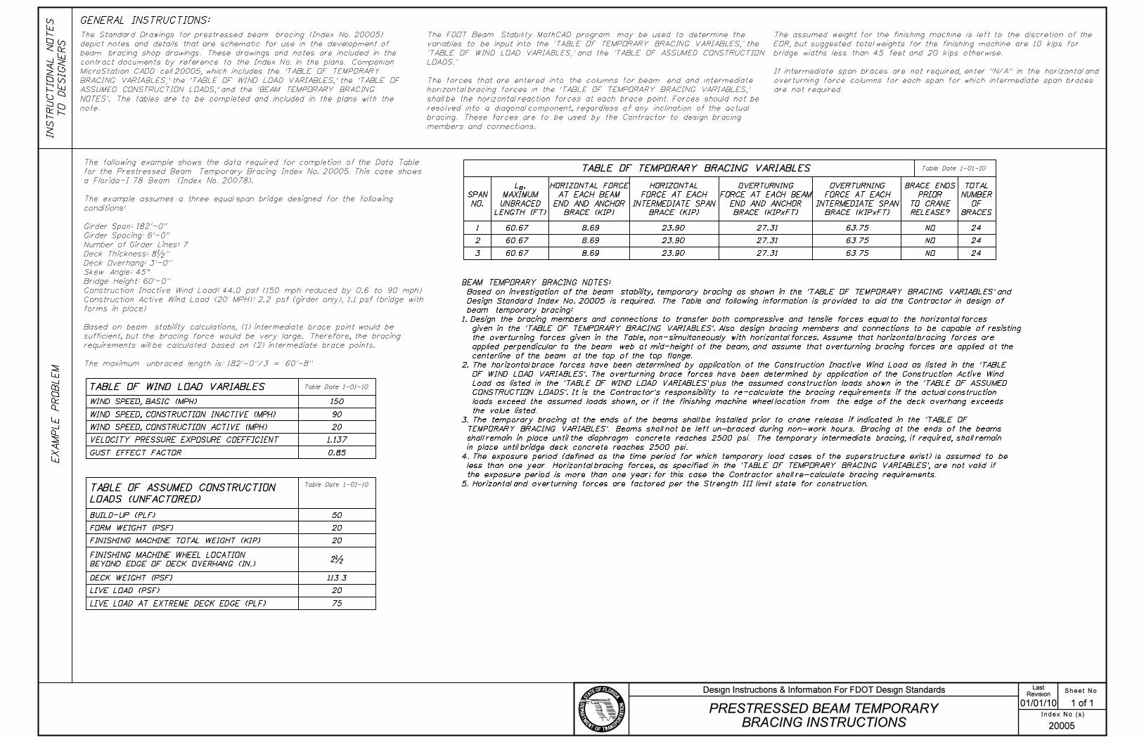
The Standard Drawings for prestressed beam bracing (Index No. 20005)
depict notes and details that are schematic for use in the development of
beam bracing shop drawings. These drawings and notes are included in the
contract documents by reference to the Index No. in the plans. Companion
MicroStation CADD cell 20005, which includes the ’TABLE OF TEMPORARY
BRACING VARIABLES,’ the ’TABLE OF WIND LOAD VARIABLES,’ the ’TABLE OF
ASSUMED CONSTRUCTION LOADS,’ and the ’BEAM TEMPORARY BRACING
NOTES’. The tables are to be completed and included in the plans with the
note.
The following example shows the data required for completion of the Data Table
for the Prestressed Beam Temporary Bracing Index No. 20005. This case shows
a Florida-I 78 Beam (Index No. 20078).
The example assumes a three equal span bridge designed for the following
conditions:
Girder Span: 182’-0"
Girder Spacing: 6’-0"
Number of Girder Lines: 7
Deck Thickness: 8�"
Deck Overhang: 3’-0"
Skew Angle: 45^
Bridge Height: 60’-0"
Construction Inactive Wind Load: 44.0 psf (150 mph reduced by 0.6 to 90 mph)
Construction Active Wind Load (20 MPH): 2.2 psf (girder only), 1.1 psf (bridge with
forms in place)
Based on beam stability calculations, (1) intermediate brace point would be
sufficient, but the bracing force would be very large. Therefore, the bracing
requirements will be calculated based on (2) intermediate brace points.
The maximum unbraced length is: 182’-0"/3 = 60’-8"
The FDOT Beam Stability MathCAD program may be used to determine the
variables to be input into the ’TABLE OF TEMPORARY BRACING VARIABLES,’ the
’TABLE OF WIND LOAD VARIABLES,’ and the ’TABLE OF ASSUMED CONSTRUCTION
LOADS.’
The forces that are entered into the columns for beam end and intermediate
horizontal bracing forces in the ’TABLE OF TEMPORARY BRACING VARIABLES,’
shall be the horizontal reaction forces at each brace point. Forces should not be
resolved into a diagonal component, regardless of any inclination of the actual
bracing. These forces are to be used by the Contractor to design bracing
members and connections.
The assumed weight for the finishing machine is left to the discretion of the
EOR, but suggested total weights for the finishing machine are 10 kips for
bridge widths less than 45 feet and 20 kips otherwise.
If intermediate span braces are not required, enter "N/A" in the horizontal and
overturning force columns for each span for which intermediate span braces
are not required.
BEAM TEMPORARY BRACING NOTES:
Based on investigation of the beam stability, temporary bracing as shown in the ’TABLE OF TEMPORARY BRACING VARIABLES’ and
Design Standard Index No. 20005 is required. The Table and following information is provided to aid the Contractor in design of
beam temporary bracing:
1. Design the bracing members and connections to transfer both compressive and tensile forces equal to the horizontal forces
given in the ’TABLE OF TEMPORARY BRACING VARIABLES’. Also design bracing members and connections to be capable of resisting
the overturning forces given in the Table, non-simultaneously with horizontal forces. Assume that horizontal bracing forces are
applied perpendicular to the beam web at mid-height of the beam, and assume that overturning bracing forces are applied at the
centerline of the beam at the top of the top flange.
2. The horizontal brace forces have been determined by application of the Construction Inactive Wind Load as listed in the ’TABLE
OF WIND LOAD VARIABLES’. The overturning brace forces have been determined by application of the Construction Active Wind
Load as listed in the ’TABLE OF WIND LOAD VARIABLES’ plus the assumed construction loads shown in the ’TABLE OF ASSUMED
CONSTRUCTION LOADS’. It is the Contractor’s responsibility to re-calculate the bracing requirements if the actual construction
loads exceed the assumed loads shown, or if the finishing machine wheel location from the edge of the deck overhang exceeds
the value listed.
3. The temporary bracing at the ends of the beams shall be installed prior to crane release if indicated in the ’TABLE OF
TEMPORARY BRACING VARIABLES’. Beams shall not be left un-braced during non-work hours. Bracing at the ends of the beams
shall remain in place until the diaphragm concrete reaches 2500 psi. The temporary intermediate bracing, if required, shall remain
in place until bridge deck concrete reaches 2500 psi.
4. The exposure period (defined as the time period for which temporary load cases of the superstructure exist) is assumed to be
less than one year. Horizontal bracing forces, as specified in the ’TABLE OF TEMPORARY BRACING VARIABLES’, are not valid if
the exposure period is more than one year; for this case the Contractor shall re-calculate bracing requirements.
5. Horizontal and overturning forces are factored per the Strength III limit state for construction.
Sheet No.Revision
07/01/09 1 of 1
Last
Index No.(s)
Design Instructions & Information For FDOT Design Standards

Sheet No.Revision
07/01/05 1 of 1
Last
Index No.(s)
Design Instructions & Information For FDOT Design Standards
Sheet No.Revision
07/01/05 1 of 2
Last
Index No.(s)
Design Instructions & Information For FDOT Design Standards

Sheet No.Revision
07/01/05 2 of 2
Last
Index No.(s)
Design Instructions & Information For FDOT Design Standards
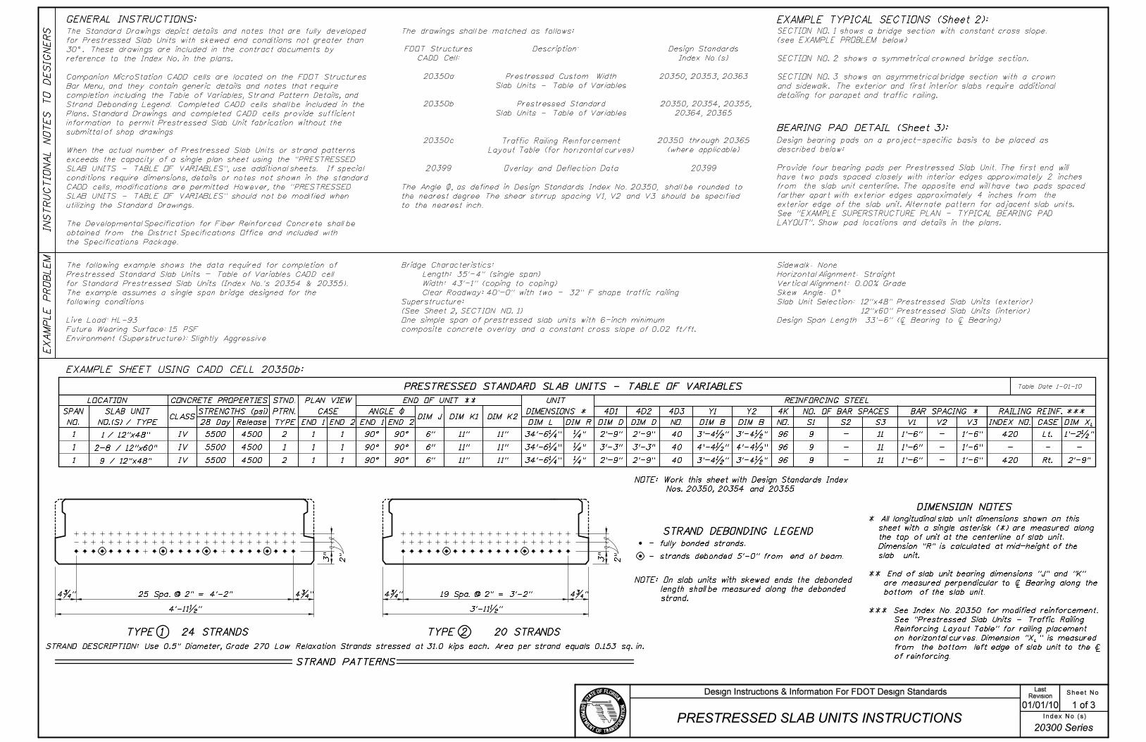
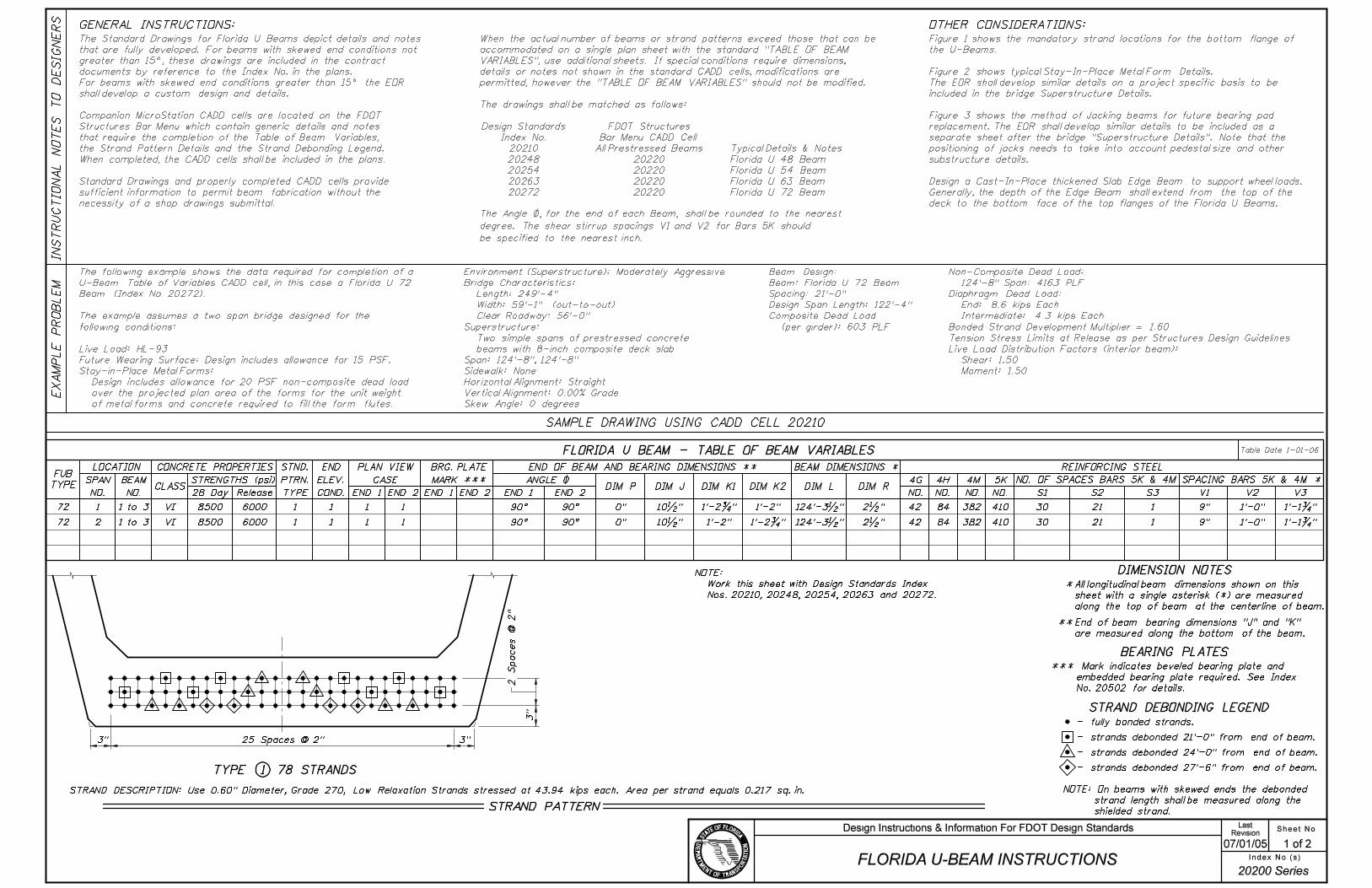
STRAND PATTERNS
STRAND DESCRIPTION: Use 0.5" Diameter, Grade 270 Low Relaxation Strands stressed at 31.0 kips each. Area per strand equals 0.153 sq. in.
TYPE 1 24 STRANDS TYPE 2 20 STRANDS
2"
3"
3"
4’-11�"
25 Spa. @ 2" = 4’-2"4�" 4�" 4�" 4�"19 Spa. @ 2" = 3’-2"
3’-11�"
GENERAL INSTRUCTIONS:
IN
ST
RU
CTIO
NA
L
NO
TE
S
TO
DE
SIG
NE
RS
EX
AM
PL
E
PR
OB
LE
M
Sheet No.Revision
01/01/10 1 of 3
Last
Index No.(s)
Design Instructions & Information For FDOT Design Standards
PRESTRESSED SLAB UNITS INSTRUCTIONS
20300 Series
The drawings shall be matched as follows:
Description:FDOT Structures
CADD Cell:
20350a
20350b
20350c
20399
EXAMPLE TYPICAL SECTIONS (Sheet 2):
BEARING PAD DETAIL (Sheet 3):
Table Date 1-01-10
CLASS
CONCRETE PROPERTIES
STRENGTHS (psi)
28 Day Release
STND.
PTRN.
TYPE
PLAN VIEW
CASE
END 1 END 2
ANGLE \
END 1 END 2DIM J DIM K1 DIM K2
DIM L DIM R
REINFORCING STEEL
V3V2V1
UNIT
DIMENSIONS *
DIMENSION NOTES
PRESTRESSED STANDARD SLAB UNITS - TABLE OF VARIABLES
BAR SPACING *
LOCATION
SPAN
NO.
SLAB UNIT 4K
NO. S1 S2 S3
NO. OF BAR SPACES
CASE L
RAILING REINF. ***
DIM XINDEX NO.
END OF UNIT **
DIM D DIM BDIM D
4D1 4D2 4D3
NO. DIM B
Y1 Y2
STRAND DEBONDING LEGEND
- fully bonded strands.
NOTE: On slab units with skewed ends the debonded
length shall be measured along the debonded
strand.
IV
IV
IV
1
1
1
2
1
2
1
1
1 1
1
1 6"
6"
6"
�"
�"
�"
40
40
40 96
96
96 9
9
9 -
-
-
11
11
11
-
-
-
- -
5500
5500
5500
4500
4500
4500
90É 90É
90É 90É
90É 90É
11"
11"
11"
11"
11"
11"
34’-6�"
34’-6�"
34’-6�"
2’-9"
3’-3"
2’-9"
2’-9"
3’-3"
2’-9"
EXAMPLE SHEET USING CADD CELL 20350b:
3’-4�" 3’-4�"
4’-4�" 4’-4�"
3’-4�" 3’-4�"
1’-6"
1’-6"
1’-6"
1’-6"
1’-6"
1’-6"
420
420
-
Lt.
Rt.
1’-2�"
2’-9"
Prestressed Custom Width
Slab Units - Table of Variables
Prestressed Standard
Slab Units - Table of Variables
Traffic Railing Reinforcement
Layout Table (for horizontal curves)
Overlay and Deflection Data
2" - strands debonded 5’-0" from end of beam.
NO.(S) / TYPE
1 / 12"x48"
2-8 / 12"x60"
9 / 12"x48"
The following example shows the data required for completion of
Prestressed Standard Slab Units - Table of Variables CADD cell
for Standard Prestressed Slab Units (Index No.’s 20354 & 20355).
The example assumes a single span bridge designed for the
following conditions:
Live Load: HL-93
Future Wearing Surface: 15 PSF
Environment (Superstructure): Slightly Aggressive
Bridge Characteristics:
Length: 35’-4" (single span)
Width: 43’-1" (coping to coping)
Clear Roadway: 40’-0" with two - 32" F shape traffic railing
Superstructure:
(See Sheet 2, SECTION NO. 1)
One simple span of prestressed slab units with 6-inch minimum
composite concrete overlay and a constant cross slope of 0.02 ft/ft.
Sidewalk: None
Horizontal Alignment: Straight
Vertical Alignment: 0.00% Grade
Skew Angle: 0^
Slab Unit Selection: 12"x48" Prestressed Slab Units (exterior)
12"x60" Prestressed Slab Units (interior)
Design Span Length: 33’-6" (| Bearing to | Bearing)
NOTE: Work this sheet with Design Standards Index
Nos. 20350, 20354 and 20355
SECTION NO. 1 shows a bridge section with constant cross slope.
(see EXAMPLE PROBLEM below)
SECTION NO. 2 shows a symmetrical crowned bridge section.
SECTION NO. 3 shows an asymmetrical bridge section with a crown
and sidewalk. The exterior and first interior slabs require additional
detailing for parapet and traffic railing.
Design bearing pads on a project-specific basis to be placed as
described below:
Provide four bearing pads per Prestressed Slab Unit. The first end will
have two pads spaced closely with interior edges approximately 2 inches
from the slab unit centerline. The opposite end will have two pads spaced
farther apart with exterior edges approximately 4 inches from the
exterior edge of the slab unit. Alternate pattern for adjacent slab units.
See "EXAMPLE SUPERSTRUCTURE PLAN - TYPICAL BEARING PAD
LAYOUT". Show pad locations and details in the plans.
L
* All longitudinal slab unit dimensions shown on this
sheet with a single asterisk (*) are measured along
the top of unit at the centerline of slab unit.
Dimension "R" is calculated at mid-height of the
slab unit.
** End of slab unit bearing dimensions "J" and "K"
are measured perpendicular to | Bearing along the
bottom of the slab unit.
*** See Index No. 20350 for modified reinforcement.
See "Prestressed Slab Units - Traffic Railing
Reinforcing Layout Table" for railing placement
on horizontal curves. Dimension "X " is measured
from the bottom left edge of slab unit to the |
of reinforcing.
The Angle \, as defined in Design Standards Index No. 20350, shall be rounded to
the nearest degree. The shear stirrup spacing V1, V2 and V3 should be specified
to the nearest inch.
Design Standards
Index No.(s)
20350, 20353, 20363
20350, 20354, 20355,
20364, 20365
20350 through 20365
(where applicable)
20399
The Standard Drawings depict details and notes that are fully developed
for Prestressed Slab Units with skewed end conditions not greater than
30^. These drawings are included in the contract documents by
reference to the Index No. in the plans.
Companion MicroStation CADD cells are located on the FDOT Structures
Bar Menu, and they contain generic details and notes that require
completion including the Table of Variables, Strand Pattern Details, and
Strand Debonding Legend. Completed CADD cells shall be included in the
Plans. Standard Drawings and completed CADD cells provide sufficient
information to permit Prestressed Slab Unit fabrication without the
submittal of shop drawings.
When the actual number of Prestressed Slab Units or strand patterns
exceeds the capacity of a single plan sheet using the "PRESTRESSED
SLAB UNITS - TABLE OF VARIABLES", use additional sheets. If special
conditions require dimensions, details or notes not shown in the standard
CADD cells, modifications are permitted. However, the "PRESTRESSED
SLAB UNITS - TABLE OF VARIABLES" should not be modified when
utilizing the Standard Drawings.
The Developmental Specification for Fiber Reinforced Concrete shall be
obtained from the District Specifications Office and included with
the Specifications Package.

48"30"
48"48"
48"
1 2 3 4 5 6 7 8 9
43’-1"
20’-0"
1’-6�"
20’-0"
1’-6�"
1’-6�"
20’-0"
43’-1"
20’-0"
1’-6�"
1’-6" 20’-0" 20’-0"
1’-6�"
5’-0" Min.
1’-0" or 1’-3"
1’-0" or 1’-3"
1’-0"
6" Min. C.I.P. Overlay
6" Min. C.I.P. Overlay
6" Min. C.I.P. Overlay
1’-0"
49’-0�"
EXAMPLE SECTION NO. 2
EXAMPLE SECTION NO. 3
EXAMPLE SECTION NO. 1
�" �" �"�" �" �"
�" �"
�" �" �" �" �" �" �" �"�"
�" �" �"�" �" �" �" �" �" �"
Notes to Designer:
***
#
*Gaps between slab units may be
increased a maximum of �" to
accommodate the total bridge width.
Show gap width dimensions in the
plans.
**Where possible, locate slab unit
keyway joints under cross slope
break points in the deck overlay. It
is ideal for the slab cross slopes to
match adjacent overlay cross slopes
to minimize overlay heights and rebar
lengths for traffic railing anchorage
reinforcement.
***Locate slab unit keyway joints
outside the limits of traffic railing
anchorage reinforcement.
P.I.**
P.I.**
LEGEND:
- Slab Unit Number
SPSU - Standard Width Prestressed
Slab Unit
CPSU - Custom Width Prestressed
Slab Unit
SPSU
7 ~ 60" SPSU
SPSU
48"
30"29�"
30"
CPSU SPSU
6 ~ 60" SPSU
SPSU CPSU
CPSU
8 ~ 60" SPSU
SPSU CPSU
| Construction & PGL
| Construction & PGL
| Construction & PGL
Slope: 0.02 Ft/Ft
Slope: 0.02 Ft/Ft
Slope: 0.02 Ft/Ft
Slope: 0.02 Ft/Ft
Slope: 0.02 Ft/Ft
Sheet No.Revision
01/01/10 2 of 3
Index No.(s)
PRESTRESSED SLAB UNITS INSTRUCTIONS
LastDesign Instructions & Information For FDOT Design Standards
20300 Series

Direction of Stationing
�" = 1’
3"
3"
1"
Exp. Jt.
1"
Exp. Jt.
35’-2" Cast in Place Deck Overlay
1’-
10"
11"11"
PLAN
ELEVATION
50 Durometer
(36 Pads Required)
8"
8"
�"
12"x4
8"
SP
SU
EXAMPLE NEOPRENE
BEARING PAD DETAIL
12"x4
8"
SP
SU
Backer Rod & Non-Shrink Grout
(Typ. ~ see Index No. 20350)
EXAMPLE SUPERSTRUCTURE PLAN -
TYPICAL BEARING PAD LAYOUT
4’-
6�
"5’-
0"
5’-
0"
4’-
6�
"
1’-
10"
(T
yp.)
(T
yp.)
(T
yp.)
6"
| Pad
| Pad
6"
(T
yp.)
Traffic Railing
(See Index No. 420)
Traffic Railing
(See Index No. 420)
35’-4" Span
| Pad
| Pad
(T
yp.)
6"
6"
(T
yp.)
| Pad
| Pad
| Pad
| Pad
(T
yp.)
(T
yp.)
8"x8"x�" Neoprene
Bearing Pads (Typ.)
1’-
4"
1’-
4"
| Slab Unit 1
| Slab Unit 9
Bars 4B1 paired
with Bars 5B1 (Typ.)
Bars 4B1 paired
with Bars 5B1 (Typ.)
Bars 5B1 (Typ.)
4" 4"
Bars 5B2
(Typ.)
44
~
Bars 5
B1
@
1’-
0"̈
5’-
0�
"5’-
0�
"5’-
0�
"5’-
0�
"
| Bearing
Pads
| Bearing
Pads
1’-
11�
"1’-
11�
"
Sheet No.Revision
01/01/10 3 of 3
Index No.(s)
PRESTRESSED SLAB UNITS INSTRUCTIONS
LastDesign Instructions & Information For FDOT Design Standards
20300 Series
71 ~ Bars 5B2 @ 6"¨
| Construction, PGL, & | Slab Unit 5
| Slab Unit 2
| Slan Unit 3
| Slab Unit 4
| Slab Unit 6
| Slab Unit 7
| Slab Unit 8
Coping
Gutter Line
Gutter Line
43’-
1"
20’-
0"
20’-
0"
7
~ 12"x60" S
PS
U
1’-
6�
"1’-
6�
"
Coping
Sheet No.Revision
01/01/09 1 of 1
Last
Index No.(s)
Design Instructions & Information For FDOT Design Standards

Sheet No.Revision
07/01/09 1 of 1
Last
Index No.(s)
Design Instructions & Information For FDOT Design Standards
Sheet No.Revision
07/01/05 1 of 1
Last
Index No.(s)
Design Instructions & Information For FDOT Design Standards