Embed Size (px)
Citation preview

design improvement of the longerons of a trainer
aircraft towards better corrosion resistance
U. Schuster
Pilatus Aircraft Ltd.
Stans, CH-6371
Switzerland
Abstract
The upper and lower Longerons in the Pilatus PC-9(M) principle fuselage structure are made fromAA2024-T3511 extruded shapes. This alloy product form is widely used in the aircraft industry, though ithas shown poor resistance to exfoliation corrosion in the recent past. The ultimate ambition of this paper isto improve the Longeron corrosion resistance by design. Therefore, general exfoliation corrosion issues andrecent advances in aluminium alloys and metallic fuselage design are reviewed. A good design approach isfound to be a material supersedure through AA2124-T851 plate in conjunction with integrally machining. Toreduce production costs, both upper Longerons are separated into a machined forward and a machined aftsection which are connected by a bolted lap-joint. This joint is a major design change and thus invalidatesthe aircraft fatigue test. In this paper, we perform a joint fatigue analysis using FEM in combination with astrain-life method to predict the minimal crack initiation life and thus allow for FAR-23 certification withoutstructural testing.
1. INTRODUCTION
The Pilatus PC-9(M) is a turboprop trainer aircraftcertified under FAR-23 regulations. There are 306 air-craft in service (as per June 2011), including PC-9(M)and the similar products PC-9 and PC-7MkII hav-ing an identical main fuselage structure. Figure 1(appended) shows its conventional aluminium semi-monocoque design with blanked canopy, fuselage skinand engine cowling. As principle structural elementsthere are two upper and two lower Longerons in theforward fuselage.Each Longeron is manufactured from an extrudedU-section of the WL 3.1354-T3511 aluminium alloywhich is essentially equal to AA2024. This legacy alloyis still widely used, though it has shown poor resistanceto exfoliation corrosion in the recent past. Duringmaintenance, this type of corrosion was encounteredon several Longeron locations of several PC-9(M) air-craft. As Longeron failure is catastrophic design im-provements are mandatory to provide increased corro-sion resistance.Therefore, let us briefly review material and designrelated factors which ultimately initiate and promotecorrosion. An introduction to modern aluminium ma-terials and metallic fuselage design enables us to findfavourable design improvements. Finally, fatigue anal-yses must be performed by means of FEM in conjunc-tion with a strain-life approach to allow for FAR-23certification without structural airframe testing.
2. STATE OF THE ART
2.1. Aluminium Alloys
Over the past decade, the Aging Aircraft Communityhas invested heavily in research and developmentfor the characterization, prediction, remediation,and prevention of aircraft corrosion. Due to theseefforts, which were focused on legacy alloys, corrosionresistance could have been improved dramatically [1].Apart from advanced legacy alloys, next generationAluminun-Lithium alloys, like AA2X9X, evolved withsuperior properties in terms of corrosion resistance,density, stiffness and static strength.Table 1 summarizes applicable high strength anddamage tolerant aluminium alloys and their resis-tance to exfoliation corrosion (EXCO), consideringlegacy alloys (AA2024, AA7075) as well as promisingadvanced legacy alloys (AA2124, AA7475) and Al-Lialloys (AA2099, AA2196). Ratings "A" through "D"indicate the corrosion resistance to EXCO, where "A"means best and "D" means lowest resistance. Thesevalues refer to the short transverse direction (ST),as the ST-direction is generally most susceptible andthus governs the total material corrosion performance[2]. Note, that EXCO resistance is also a measurefor the material’s stress corrosion cracking (SCC)characteristics. Generally, those alloys and tempersthat are susceptible to EXCO are also prone to SCCand vice versa [2].
Deutscher Luft- und Raumfahrtkongress 2012
1
DocumentID: 281511
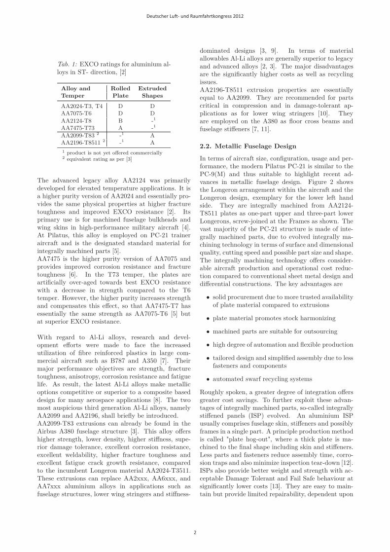
Tab. 1: EXCO ratings for aluminium al-loys in ST- direction, [2]
Alloy and Rolled Extruded
Temper Plate Shapes
AA2024-T3, T4 D DAA7075-T6 D D
AA2124-T8 B -1
AA7475-T73 A -1
AA2099-T83 2 -1 AAA2196-T8511 2 -1 A
1 product is not yet offered commercially2 equivalent rating as per [3]
The advanced legacy alloy AA2124 was primarilydeveloped for elevated temperature applications. It isa higher purity version of AA2024 and essentially pro-vides the same physical properties at higher fracturetoughness and improved EXCO resistance [2]. Itsprimary use is for machined fuselage bulkheads andwing skins in high-performance military aircraft [4].At Pilatus, this alloy is employed on PC-21 traineraircraft and is the designated standard material forintegrally machined parts [5].AA7475 is the higher purity version of AA7075 andprovides improved corrosion resistance and fracturetoughness [6]. In the T73 temper, the plates areartificially over-aged towards best EXCO resistancewith a decrease in strength compared to the T6temper. However, the higher purity increases strengthand compensates this effect, so that AA7475-T7 hasessentially the same strength as AA7075-T6 [5] butat superior EXCO resistance.
With regard to Al-Li alloys, research and devel-opment efforts were made to face the increasedutilization of fibre reinforced plastics in large com-mercial aircraft such as B787 and A350 [7]. Theirmajor performance objectives are strength, fracturetoughness, anisotropy, corrosion resistance and fatiguelife. As result, the latest Al-Li alloys make metallicoptions competitive or superior to a composite baseddesign for many aerospace applications [8]. The twomost auspicious third generation Al-Li alloys, namelyAA2099 and AA2196, shall briefly be introduced.AA2099-T83 extrusions can already be found in theAirbus A380 fuselage structure [3]. This alloy offershigher strength, lower density, higher stiffness, supe-rior damage tolerance, excellent corrosion resistance,excellent weldability, higher fracture toughness andexcellent fatigue crack growth resistance, comparedto the incumbent Longeron material AA2024-T3511.These extrusions can replace AA2xxx, AA6xxx, andAA7xxx aluminium alloys in applications such asfuselage structures, lower wing stringers and stiffness-
dominated designs [3, 9]. In terms of materialallowables Al-Li alloys are generally superior to legacyand advanced alloys [2, 3]. The major disadvantagesare the significantly higher costs as well as recyclingissues.AA2196-T8511 extrusion properties are essentiallyequal to AA2099. They are recommended for partscritical in compression and in damage-tolerant ap-plications as for lower wing stringers [10]. Theyare employed on the A380 as floor cross beams andfuselage stiffeners [7, 11].
2.2. Metallic Fuselage Design
In terms of aircraft size, configuration, usage and per-formance, the modern Pilatus PC-21 is similar to thePC-9(M) and thus suitable to highlight recent ad-vances in metallic fuselage design. Figure 2 showsthe Longeron arrangement within the aircraft and theLongeron design, exemplary for the lower left handside. They are integrally machined from AA2124-T8511 plates as one-part upper and three-part lowerLongerons, screw-joined at the Frames as shown. Thevast majority of the PC-21 structure is made of inte-grally machined parts, due to evolved integrally ma-chining technology in terms of surface and dimensionalquality, cutting speed and possible part size and shape.The integrally machining technology offers consider-able aircraft production and operational cost reduc-tion compared to conventional sheet metal design anddifferential constructions. The key advantages are
• solid procurement due to more trusted availabilityof plate material compared to extrusions
• plate material promotes stock harmonizing
• machined parts are suitable for outsourcing
• high degree of automation and flexible production
• tailored design and simplified assembly due to lessfasteners and components
• automated swarf recycling systems
Roughly spoken, a greater degree of integration offersgreater cost savings. To further exploit these advan-tages of integrally machined parts, so-called integrallystiffened panels (ISP) evolved. An aluminium ISPusually comprises fuselage skin, stiffeners and possiblyframes in a single part. A principle production methodis called "plate hog-out", where a thick plate is ma-chined to the final shape including skin and stiffeners.Less parts and fasteners reduce assembly time, corro-sion traps and also minimize inspection tear-down [12].ISPs also provide better weight and strength with ac-ceptable Damage Tolerant and Fail Safe behaviour atsignificantly lower costs [13]. They are easy to main-tain but provide limited repairability, dependent upon
Deutscher Luft- und Raumfahrtkongress 2012
2

stringer(-foot) design. A major technical challenge toISP structures is damage tolerance and fail safety, suchas the arrest of a two-bay crack by integral tear straps[14]. Crack deflection and crack arrest mechanisms arecurrently being investigated [15] and would require ex-tensive review, if it should come to ISP application forfuture PC-9(M) fuselages.
3. LONGERON DESIGN
Reference [16] introduces promising structural con-cepts for improved Longerons. Among the seven con-sidered concepts there are machined split Longeronsas well as intergally machined Longerons, heat treat-ment options, Longeron integration into an ISP andothers. The main criteria applied in the concept eval-uation scheme claim increased EXCO resistance, lowdevelopment and manufacturing costs and a produc-tion process that provides repeatable Longeron prop-erties as well as the possibility for outsourcing. In thispaper, we will focus on the upper Longerons as theyare more interesting from a structural standpoint.In [16] the most favourable design turned out to bea separation of each upper Longeron into a machinedforward and a machined aft section which are con-nected by a bolted lap-joint. Figure 3 shows the jointlocation between frame (FR) 3D and FR 4. The gen-eral Longeron shape remains unchanged, except forthickened lands at the joint to provide for high bearingloads through the fasteners. Figure 4 shows the lap-joint design on the upper left hand Longeron through avirtual skin cutout, looking from outboard. The threesegments of the Longeron U-section can be consideredas an outboard, top and inboard flange. At the joint,each flange applies two straps. As result, there arethree symmetrical double lap joints at each segmentof the Longeron U-section. The outboard side addi-tionally comprises the fuselage skin as a strap to avoidinter-rivet buckling due to wide rivet spacing. Furtherdesign details are presented in [16].The strap material is a high strength Titanium alloyTi-6Al-4V for the inboard and outboard flange strapsand SAE4130 HT125 steel for the top flange straps.In conjunction with high strength Hi-Tigue fastenersfrom Ti-6Al-4V this design allows for a compact joint.For the Longeron material, the alloy AA2124-T851in the form of plate is chosen as it provides goodEXCO resistance, namely "A" in longitudinal (L)and long transverse (LT) direction and "B" throughplate thickness (ST). Moreover, this alloy is the des-ignated standard material for machined parts at Pi-latus. Longerons from this material promote furtherstock harmonization and profit by supply guarantee.Subsequent Longeron fatigue analyses require particu-lar material data, namely the Coffin-Manson strain-lifecurve and the Ramberg-Osgood curve for cyclic stress-strain. These information are currently available for
the AA2X24 family, but not for Al-Li alloys. In termsof material costs and recycling issues the chosen mate-rial is significantly cheaper than Al-Li. With regard toa direct material supersedure, the A-Basis stress allow-ables of the new Longeron material AA2124-T851 arethroughout superior to WL3.1354-T3511 and AA2024-T3511 [2, 17]. Attention must be given to a slightlylower Young’s modulus E. Generally, less Longeronmaterial stiffness would distribute Longeron load intostringers and skin and thus demands an increasedLongeron cross section area to compensate for. How-ever, the chemical composition of AA2024, WL3.1354and AA2124 is basically identical except for the al-lowed purity [6, 18, 19]. So from a composition pointof view, every AA2124 is also an AA2024 and also aWL3.1354. Hence, applying the stiffness provided in[2] would underestimate the Longeron load and prob-ably cause a fatigue problem. So it is conservative toassume AA2024’s modulus for the new Longeron ma-terial, too. As result, AA2124 provides similar staticand fatigue properties and can supersede the incum-bent Longeron material AA2024.
4. FATIGUE ANALYSIS
The PC-9(M) primary structure is certified underFAR-23 according to the Safe Life philosophy. Thedesign fatigue life is 10’000 flight hours, correspondingto 20’000 landings, which was verified by a Full ScaleFatigue Test (FSFT). The introduction of the joint isa major design change and thus invalidates the FSFT.In this section we will perform a fatigue life predic-tion for the upper Longeron joint in order to enablecertification without testing. It is most desired notto introduce any inspection cycles but to retain theSafe Life concept and thus minimize direct operatingcosts for the improved Longerons. Hereinafter, we willconsider the left hand joint only, due to symmetry.
4.1. Strain-Life approach
Critical locations for crack initiation on the Longeronjoint are the fastener holes. Shear loaded boltedjoints are most susceptible to crack initiation and acommon source of fatigue failure in aircraft structures[20]. Fastener holes act as a notch and cause highstress concentrations at the root of the notch wherelocal plastic deformation may occur. As long as thesurrounding material is still in the elastic range thestrain based approach is applicable. Strain-Life refersto low cycle fatigue and is widely used at present [21].Compared to high cycle fatigue methods, like theStress-Life approach using S-N curves, the Strain-Lifeapproach is more conservative as the elasto-plasticmaterial behavior is best considered in terms of strain[21, 22].
Deutscher Luft- und Raumfahrtkongress 2012
3

At Pilatus, the N40 computer program is em-ployed to calculate the crack initiation life from thefollowing input data:
• Material Strain-Life Curve fitted to the Coffin-Manson form
• Material Cyclic Stress-Strain Curve fitted to theRamberg-Osgood form
• Discrete sequence of maximum principle stress ex-actly at the root of the notch representing a cer-tain number of cycles
N40 applies a straightforward algorithm. The track-ing of the stress sequence accounts for material hys-teresis loops and applies the Neuber’s Rule, which isan approximate relationship between stress and strainwhen the material is in the plastic range. The algo-rithm proceeds with sequence counting of range pairs.The Smith-Watson-Topper equation accounts for themean stress effect, so that the partial damages of eachstress cycle can finally be summed up by the com-monly used Miner’s Rule and give the crack initiationlife. With regard to input data, both material proper-ties are available from in-house tests. What we wantto focus on is the derivation of the critical stress se-quences, namely at the fastener holes.The stress at the root of a fastener hole is hereinafterreferred to as notch stress. On any fastener hole, thenotch stress depends on the combination of the outerjoint loads, i.e. Longeron normal load, skin normalload and skin shear. Hence, the notch stress sequencedepends on the combination of the individual load se-quences. To decrease the degree of freedom and toease the derivation of the stress sequence it would beadvantageous, if the stress could be related to onlyone single load. Therefore, the above joint loads arerequired to have a constant ratio. However, any flightmanoeuvre comes with a unique ratio of joint loads.Moreover, their individual contribution to notch stressis nontrivial and thus requires a separate analysis foreach flight manoeuvre to find the exact sequence ofnotch stresses. This is not practicable at all and somesimplification must be made in order to derive a rep-resentative stress sequence from only one master loadsequence.Therefore, our approach is to assume that the majorityof flight manoeuvres is symmetrical, i.e. the fuselage ismainly subjected to bending about the aircraft span-wise axis. For all magnitudes of bending moments theratio of shear and tension loads in the fuselage portionnear the joint can be assumed as being nearly constant.Due to this, we can relate each outer joint load to onegoverning load Fref . As result, the value of Fref doesperfectly define the joint load condition. Moreover, asour strain based approach is associated to maximumprinciple stress, we can assume the stress at each fas-tener hole to vary with Fref in a linear manner. To
establish the linear correlation between the referenceload Fref and resulting stresses at each fastener hole,we will developed a local FEM model of the joint.
4.2. Global and local FEM models
Figure 6 shows the considered joint model as afuselage cutout including the Longeron forward andaft section, joint straps, a split packing between skinand Longeron, the fasteners and a portion of theadjacent skin, which extends to the joint’s far-field.All joint members are modelled with least materialthickness according to their dimensional tolerances.The simplified Hi-Tigue bolts, nuts and rivets repre-sent a transition fit through zero gap. We use solidparabolic tetrahedral elements (10-noded) throughoutas these elements are most suitable to capture highstress gradients in riveted or bolted connections [23].To model the contact between the fasteners and thejoint members, NX NASTRAN offers linear contactproperties for solid mesh. Here, "linear" denotes aniterative solution from numerous linear sub solutions.Hence, this method is limited to small displacementsand linear material properties. A contact pair, such asbolt shaft and strap hole, comprises two faces whichcan potentially interact. In the present method,attention is given to similar mesh sizes of contactingfaces as this makes results most accurate [24] and notdependent upon a master/slave definition. Moreover,we employ solid elements for the fasteners, whichis recommended for bolted structures [23]. Othermethods utilize several coaxial line elements as boltshaft axis and radial line elements extending from theshaft axis to the hole face in several layers, wherethe element nodes must be matched. To representthe real bolt behavior, the radial line elements mustbe active in compression and inactive in tension(zero stiffness). This method disables linear analysisand cannot represent bearing stress directly. In ourmethod, element nodes need not be coincident andless modelling time allows for rapid design iterations.Moreover, the solid bolts enable the introduction ofbolt preload resulting in pressure underneath the boltand nut head surface which enables higher accuracyof the fastener hole’s near field stress. To furtherpromote the conservative nature of this analysis wedefine a rather low friction coefficient not to distributethe joint loads through the strap faces but throughthe bolts.
The yet unknown linear correlation between thereference load Fref and the corresponding notchstresses can be derived from two load conditions,preferably the zero load condition and some referencecondition. The latter must be a symmetrical ma-noeuvre, as discussed above. Therefore we use a +7gsteady pitching manoeuvre which is the critical static
Deutscher Luft- und Raumfahrtkongress 2012
4

load case for the Longeron joint region. Figure 5shows the global PC-9(M) FEM model and the corre-sponding airframe deformation (overdone). Freebody(FB) loads are extracted for the highlighted elementsmarking the joint region. Their introduction into thelocal joint FEM model provides the maximum valuesof principle stress σ on each fastener hole at thiscertain loadcase. Let us define the Longeron normalload (i.e. the sum of all Longeron nodal loads) asgoverning reference Fref . As result, we can referthe notch stresses to Fref so the yet unknown stresssequence σ(t) at each fastener hole depends on theload sequence Fref (t) only.
4.3. Load and stress sequence
With regard to the FSFT some PC-9 aircraft wereequipped with several strain gauges recording thestrain sequence during representative flight missions.The FSFT did reconstruct these typical flights asrecorded. Therefore, the actuator loads were adjustedto match the in-flight aircraft deformation sequence.At Pilatus an FE model of the FSFT was developed.As the load sequences of the actuators are known,they can be introduced into the FE model and as re-sult the sequence of nodal forces on any element canbe extracted and thus establish the sequence of thereferende load Fref (t). Argument t is discrete andcounts data rows consecutively. The sequence com-prises approx. 374000 load sets (i.e. values for Fref )representing 1’000 flight hours. In [16] the sequencewas adapted to include the critical static load caseonce. Moreover, reference [16] accounts for fuselageskin buckling. The skin tensile stress in the posi-tive manoeuvres is sufficient to prevent the skin panel,which is adjacent to the joint, from buckling. This isnot true for negative manoeuvres. It is conservativelyassumed that buckled skin cannot take any normalload so the Longeron must transfer that portion, too.The critical panel buckling load was found in [16] froman analytical criterion accounting for skin normal andshear stresses. A sequence tracking checks each loadset. When the skin buckles the reference load Fref (t)additionally comprises the nodal load from the skin.Finally, Fref (t) can be introduced to the N40 program,which filters nonessential values. Remember, that thejoint stresses were assumed to linearly vary with thereference load. So the stress sequence at a fastener holeσ(t) has essentially the same shape as Fref (t). More-over, σ(t) must have its maximum σmax at the criticalload case. The stress sequence σ(t) can be normalizedto this maximum value. This normalized sequence iscounted by N40, which applies a range pair countingtechnique [21].
4.4. Results
To afford certification without testing we consider aconservative scatter factor SF = 8. So the minimumrequired Longeron joint life is
LCI,req = SF · 10′000 h(1)
= 80′000 h
where LCI denotes the crack initiation life. Based onthe normalized stress sequence, LCI can be plottedagainst any maximum sequence stress σmax. Figure7 does that for all Longeron joint member materials.The maximum values occur at the critical static loadcase which are known from the above developed FEMmodel. Finally, tab.2 presents the reserve factor
RF =LCI
LCI,req
(2)
for each Longeron joint member. As result all jointmembers provide the required crack initiation life. Theleast reserve factor RFmin = 1,67 can be found at theskin’s foremost Hi-Tigue fastener hole. This value canhardly be validated. However, reference [16] employsthe FALLSTAFF sequence as a reference, even thoughit is only applicable to the wing root of fighter aircraft.At the same skin hole the reserve factor under FALL-STAFF conditions is RFmin,F allstaff = 2,06.So the joint structural integrity is additionally demon-strated under FALLSTAFF loading. Finally, the fa-tigue performance of the the new Longeron materialcan be compared to the incumbent material to validatethe direct material supersedure. In fig.7 the incum-bent material AA2024-T3 is not included, but the fa-tigue performance essentially equals AA2024-T42. Onthe basis of the derived Longeron joint load sequence,one can say, that in the region of typical aircraft livesthe new Longeron material is well superior and candirectly supersede the incumbent. As result, the pre-sented static and fatigue analysis can finally verify thestructural integrity of the new Longerons.
4.5. Design Review
In a last step the final Longeron design shall be re-viewed in terms of structural efficiency and other pos-sible solutions. With regard to joint static and fatiguereserve factors the skin is most critical. The stress ata fastener hole is a combination of bypass load (fromskin shear and normal load) and the bearing load fromthe fastener. As the skin is highly stressed in thecritical load case, it must not be further stressed asa joint member. Therefore, different strap materialsand thicknesses can adjust the joint stiffness and un-load the skin, i.e. the fasteners do not introduce anybearing load into the skin. Figure 8 shows the lon-gitudinal skin stress for several joint strap materials.From (a) through (c) the strap stiffness increases. At
Deutscher Luft- und Raumfahrtkongress 2012
5
the joint, this increasingly takes tensile load from theskin. In case (c) the joint is too stiff and again intro-duces bearing loads through the fasteners. Case (d)represents the final joint design which was found afterseveral iterations varying materials, thicknesses andfastener arrangement. In this configuration the skinbearing loads from the Hi-Tigue fasteners are negligi-ble, i.e. the notch stress is exclusively due to bypassload.
5. SUMMARY
Exfoliation corrosion was found on Pilatus PC-9(M)Longerons. The initial problem is poor corrosionresistance of AA2024-T3 in the form of extrudedshapes. Substantial progress in the development ofmodern aluminium alloys offered promising candidatesfor improved Longerons. As machning technologyevolved the most efficient concept was found to bemachined Longerons made from an advanced legacyalloy, namely AA2124-T851 plates. Therefore, theLongerons were split into a forward and an aft section,both connected by a bolted lap-joint. The introducedjoint raised a major structural issue. In order to en-able Longeron certification without testing, thoroughfatigue analyses were performed. The critical locationsare the fastener holes, where local yielding may occur.Thus, a strain-life approach was applied. To find thecrack initiation life, a stress sequence was developedbased on the FSFT FE model that also accounts forjoint loads due to skin buckling. Finally, structuralintegrity of the Longeron joint was demonstrated forthe developed sequence as well as for the FALLSTAFFsequence. All structural analyses were performed con-servatively throughout and the rather high reserve fac-tors do not require structural testing for certificationso that development costs can be kept at a minimum.To address exfoliation corrosion as an increasingly im-portant issue on ageing airframes comprising extrudedlegacy alloys, it was shown that the new Longeron ma-terial AA2124 is suitable to directly supersede the in-cumbent AA2024 as it provides superior static and fa-tigue performance as well as corrosion resistance. Asresult, the presented Longerons do well satisfy the ul-timate ambition of this work. Their utilization forfuture PC-9, PC-7MkII and PC-9(M) aircraft can berecommended without reservation.
Deutscher Luft- und Raumfahrtkongress 2012
6
References
[1] J.P. Moran, R.J. Rioja, and E.L. Colvin. Improve-ments in Corrosion Resistance offered by NewerGeneration Aluminum Alloys for Aerospace Ap-plications, 2007. Proceedings of the Light MetalsTechnology Conference.
[2] US Department of Defense. Metallic Materialsand Elements for Aerospace Vehicle Structures,mil-hdbk-5h edition, 1998.
[3] C. Giummarra, B. Thomas, and R.J. Rioja. NewAluminum Lithium Alloys for Aerospace Applica-tions. Alcoa Lafayette Works and Alcoa TechnicalCenter, 2007.
[4] Alcoa Inc. Web Catalogue: AA2124 AluminumAlloy Plate. http://www.alcoa.com/global/
en/products/product.asp?prod_id=597&
Product=&Category=&Query=2124&page=0,[08-June-2011].
[5] Pilatus Aircraft Ltd. Aluminium, 2003. Engineer-ing Standard ES3601.
[6] E. Simmchen. Luft- und Raumfahrtwerkstoffe.Dresden University of Technology, 2007. LectureNotes.
[7] K.H. Rendigs and M. Knüwer, editors. Metal Ma-terials in Airbus A380. Izmir Global Aerospace &Offsett Conference, 2010.
[8] J. Hirsch, B. Skrotzki, and G. Gottstein. Alu-minium Alloys: Their Physical and MechanicalProperties, volume 1. Wiley-VCH, 2008.
[9] Alcoa Inc. Web Catalogue: AA2099 AluminumAlloy Plate. http://www.alcoa.com/global/
en/products/product.asp?prod_id=1827, [09-June-2011].
[10] Alcan Aerospace. 2196-T8511 Al-Li Extrusions,2007. Technical Data Sheet.
[11] Ph. Lequeu, Ph. Lassince, and T. Warner. Alu-minum Alloy Development for the Airbus A380.Advanced Materials and Processes, 2007.
[12] ASM AeroMat Conference 2006. Aerospace AlloysAdvance At Alcoa, 2006.
[13] R.G. Pettit, J.J. Wang, and C. Toh. ValidatedFeasibility Study of Integrally Stiffened Metal-lic Fuselage Panels for Reducing ManufacturingCosts, 2000. NASA Contractor Report 2000-209342.
[14] J. Munroe, K. Wilkins, and M. Gruber. Inte-gral Airframe Structures — Validated Feasibil-ity Study of Integrally Stiffened Metallic Fuselage
Panels for Reducing Manufacturing Costs, 2000.NASA Contractor Report 2000-209337.
[15] L.L. Prieto. Modelling and Analysis of CrackTurning on Aeronautical Structures. PhD thesis,Universitat Politecnica De Catalunya, 2007.
[16] U. Schuster. Design Improvement of the Upperand Lower Longerons of a Training Aircraft To-wards Better Corrosion Resistance. Pilatus Air-craft Ltd., 2011. Diplomarbeit, Technische Uni-versität Dresden.
[17] Werkstoff Leistungsblätter. WL3.1354Aluminium- Knellegierung mit etwa 4,5 Cu-1,5 Mg - 0,6 Mn, Beiblatt 1, 1983.
[18] SAE International. SAE AMS4101 - AluminumAlloy, Plate 4.4Cu - 1.5Mg - 0.60Mn (2124-T851), 1978. Aerospace Material Specification.
[19] SAE International. SAE AMS-QQ-A-200/3: Alu-minum Alloy 2024, Bar, Rod, Shapes, Tube andWire, Extruded, 1997. Aerospace Material Speci-fication.
[20] H. Huth. Zum Einfluss der Nachgiebigkeitmehrreihiger Nietverbindungen auf dieLastuebertragungs- und Lebensdauervorher-sage. Fraunhofer-Institut fuer Betriebsfestigkeit(LBF), Darmstadt, 1984.
[21] D. Quaranta. N40 Crack Initiation - User’sGuide, 2011.
[22] J. Schijve. Fatigue of Structures and Materials.Springer, 2009.
[23] T. Stehlin. Fatigue Analysis of Riveted or BoltedConnections Using the Finite Element Method,2003.
[24] EnDuraSim Pty Ltd. Contact Modelling in Femapwith NX Nastran, 2009.
Deutscher Luft- und Raumfahrtkongress 2012
7

Upper Longerons
Lower Longerons
Fig. 1: The four Longerons within the PC-9(M) structure
aft Longeron
centre Longeron
frame
screw joint
Fig. 2: PC-21 lower left hand Longeron, screw joint
FR 1 FR 3D FR 4Longeron joint location
Direction of flight
Fig. 3: PC-9(M) forward fuselage and Longeron joint location
Deutscher Luft- und Raumfahrtkongress 2012
8

Fig. 4: Longeron lap-joint design
Elements providing joint FB loads
Fig. 5: PC-9(M) FEM model without canopy at the critical load case (displacements x10).
233 mm
FR3D
100
mm
227 mmto
FR4
Solid Al-Rivet
Hi-Tigue BoltNutSkin
Dir.of flight
Fig. 6: Longeron joint FEM model
Deutscher Luft- und Raumfahrtkongress 2012
9

100
200
300
400
500
600
700
800
900
1000
103 104 105 106 107 108 109 1010 1011
Max
sequen
cest
ress
σm
ax
MP
a
Crack Initiation LifeLCI
h
AA2124-T851AA2024-T42
SAE4130Ti-6Al-4V
(Longeron)(Skin)(Top Strap)(Side Straps)
Target Life for SF = 8
Fig. 7: Max sequence stress and crack initiation life
Tab. 2: Fatigue life results
Joint Member Longeron Steel Straps Ti Straps Skin
Hi-Tigue bolts
Material AA2124-T851 SAE4130-HT125 Ti-6Al-4V AA2024-T42
σmax,seq [MPa] 293 571 415 293
LCI [h] 4,51 · 105 2,43 · 106 3,66 · 106 1,34 · 105
min. RF [-] 5,63 30,3 45,7 1,67
(a) All straps AA2121 (b) All straps Ti-6Al-4V
(c) All straps SAE4130 (d) Top Straps: SAE4130
Side Straps: Ti-6Al-4V
Fig. 8: Skin longitudinal stress in MPa for different strap materials
Deutscher Luft- und Raumfahrtkongress 2012
10