Embed Size (px)
Citation preview

www.Fisher.com
D10
3171
X01
2
Design GX Control Valve and Actuator SystemThe Fisher Design GX is a compact, state-of-the-artcontrol valve and actuator system, designed tocontrol a wide range of process liquids, gases, andvapors.
The Design GX is rugged, reliable, and easy toselect. It requires no actuator sizing -- the actuatorselection is automatic once the valve bodyconstruction is selected.
The optimized design results in reduced complexityand parts count. As a result, the cost of maintenanceis reduced.
The Design GX meets the requirements of both ENand ANSI standards. It is available with a completeaccessory package, including the FIELDVUE�DVC2000 Series integrated digital valve controller.
Features� Easy to size and select
� No actuator sizing required--selection is automatic
� Engineered for easy maintenance
� Maximum part commonality across sizes
� Replaceable trim
� Low lifetime costs
� Robust, low-profile design
� Compact field-reversible multi-spring pneumatic actuator
� Available with integrated, easy-to-calibrate DVC2000 Series Digital Valve Controller
� Valve body sizes DN 15 to DN 100 (0.5 inch through 4-inch)
� Pressure Classes PN 10-40, Class 150 and 300
W8861/IL
Figure 1. Design GX Control Valve, Actuator, and DVC2000Series Digital Valve Controller
� High capacity design
� Valve body flow passage optimized for flow stability
� Full range of materials, including alloys
� Shutoff capabilities: Class IV, V, and VI
� Rangeability of 50:1 (equal percentage)
� Optional metal bellows seal
Product Bulletin51.1:GXDecember 2004 GX Control Valve and Actuator

GX Control Valve and ActuatorProduct Bulletin
51.1:GXDecember 2004
2
W8486-3/IL
COMPACT FIELD-REVERSIBLEMULTI-SPRING ACTUATOR
INTEGRATED POSITIONERMOUNTING
NAMUR POSITIONERMOUNTING CAPABILITY
ONE-PIECE SCREWEDPACKING FOLLOWER
CLAMPED BONNET DESIGN
STANDARD LIVE-LOADED PACKING
INTEGRAL PNEUMATICPASSAGEWAYS
Figure 2. Design GX Control Valve Assembly with Stem-Guided Contoured Plug (Size DN 25/1-Inch)
ContentsFeatures 1. . . . . . . . . . . . . . . . . . . . . . . . . . . . . . . . . . Principle of Operation 4. . . . . . . . . . . . . . . . . . . . . . The Design GX Control Valve 5. . . . . . . . . . . . . . . Design GX Control Valve Specifications
and Materials of Construction 6. . . . . . . . . . . . . The Design GX Diaphragm Actuator 11. . . . . . . . . Bellows Extension Bonnet 13. . . . . . . . . . . . . . . . . Valve-Actuator Dimensions and Weights 17. . . . . Design GX Actuator Accessories 18. . . . . . . . . . . . The FIELDVUE DVC2000 Series
Digital Valve Controller 18. . . . . . . . . . . . . . . . . . Optional Positioners and Instruments 19. . . . . . . . Manual Handwheels 20. . . . . . . . . . . . . . . . . . . . . . Coefficients 22. . . . . . . . . . . . . . . . . . . . . . . . . . . . . .
Optimized valve and actuator system. Productsimplicity and ease of selection form the foundationof the Design GX. Mounted with a digital or analogpositioner, the GX provides high performance controlacross a wide range of process applications.
Compact actuator design. The multi-spring GXactuator is compact and field-reversible. (No extraparts are required to reverse the fail-action). The GXdesign has been optimized to eliminate complicatedactuator sizing procedures - once the valve bodyand port size are selected, the actuator size is fixed.
Modular design. The design architecture has beenoptimized to maximize the use of common partsacross sizes. The actuator stem and stem connectorare used across all GX sizes. Only one set ofsprings is used in each of the three actuator sizes.The plug/stem assemblies and packing sets arecommon across several sizes, as well.
Lower lifetime costs. Reduced product complexity,low parts count, and part commonality all contributeto reduced inventory and maintenance costs.
Stable flow control. The flow cavity of the DesignGX valve body has been engineered to providestable flow and reduce process variability.
GX Control Valve and ActuatorProduct Bulletin51.1:GXDecember 2004
3
LINKAGE-LESSPOSITIONFEEDBACK
PUSH-BUTTONINSTRUMENTSETUP
W8588/IL
DVC2000COVER
Figure 3. Design GX and DVC2000 Series Digital ValveController
Live-loaded packing. The Design GX comes withlive-loaded PTFE V-ring packing as standard. Thelive-loaded design helps to seal your process toconserve valuable process fluid, while reducingemissions to the environment. The long-life and highreliability of the live-loaded system also reducesmaintenance costs and process downtime. Forapplications exceeding 232�C (450�F), live-loadedULF (Ultra Low Friction) graphite packing andextension bonnets are available.
Easy maintenance. The simple screwed seat-ringand one-piece plug and stem design provide easymaintenance. Design simplicity and partscommonality contribute to reduced spares inventory.The integrated DVC2000 digital valve controllerallows easy instrument removal, without arequirement for tubing disconnection or replacement(air-to-open construction).
Longer life. Alloy valve constructions and hardenedtrim materials are available in the Design GX toincrease valve body, bonnet, and trim life.
Digital valve controller. The Design GX is availablewith the DVC2000 Series digital valve controller. TheDVC2000 is easy to use, compact, and designed for
easy mounting. It converts a 4-20 mA input signalinto a pneumatic output signal, which feeds thecontrol valve actuator. Instrument setup is performedwith a push button and liquid crystal display (LCD)interface. This interface is protected from theenvironment within a sealed enclosure. The interfacesupports multiple languages, including German,French, Italian, Spanish, Chinese, Japanese, andEnglish.
Intrinsic safety and non-incendive construction isavailable to CSA, FM, ATEX, and IEC standards. Anoptional module provides integrated limit switchesand a position transmitter.
Integrated mounting. The DVC2000 digital valvecontroller integrally mounts to the Design GXactuator, eliminating the need for mounting brackets.The DVC2000 transmits a pneumatic signal to theactuator casing via an air passage in the yoke leg,causing the valve to stroke (see figure 4). Thiseliminates the need for positioner-to-actuator tubingin the air-to-open (spring-to-close) configuration.
The DVC2000 mounting interface is identical on bothsides of the actuator yoke. This symmetrical designallows the DVC2000 to be easily moved from oneside of the valve to the other without the need torotate the actuator.
Linkage-less feedback. The DVC2000 digital valvecontroller offers as standard a non-contacting valveposition feedback system. This is a true linkage-lessdesign, which uses no levers and no touching partsbetween the valve stem and the positioner.
Additional Accessory selection. The Design GX isavailable with a variety of digital or analogpositioners besides the DVC2000 Series, as well assolenoid and limit switches. The actuator is alsocompatible with the IEC 60534-6-1 (NAMUR)positioner mounting standard.
Note
Fisher does not assume responsibilityfor the selection, use, or maintenanceof any product. Responsibility forproper selection, use, andmaintenance of any Fisher productremains solely with the purchaser andend-user.

GX Control Valve and ActuatorProduct Bulletin
51.1:GXDecember 2004
4
Principle of Operation
AIR-TO-OPEN(SPRING-TO-CLOSE)
AIR-TO-CLOSE(SPRING-TO-OPEN)
E0896-2/IL
AIR SUPPLY
AIR SUPPLY
AIR VENT
AIR VENT
Figure 4. Design GX Principle of Operation -- Actuator Air Supply
Integrated Air Supply. When mounted with theDVC2000 Series digital valve controller, the DesignGX uses an integrated actuator air supply system. Inthe air-to-open construction, air is supplied to the
lower actuator casing via a port on the actuator yokeface -- no tubing is required. In the air-to-closeconfiguration, air is supplied to the upper casing viatubing.
PLUG
SCREWED-INSEAT RING
PTFE SEAT
W9023-1
Figure 5. Design GX Control Valve with Typical Soft Seat Trim Construction (Port Sizes of 36mm - 90mm)

GX Control Valve and ActuatorProduct Bulletin51.1:GXDecember 2004
5
W8568-1/IL
CLAMPED BONNET, WITHLIVE-LOADED PTFE PACKINGAS STANDARD
PORT-GUIDED PLUG DESIGN
VALVE BODIES AVAILABLEIN EN AND ANSI PRESSURERATINGS
FLOW GEOMETRY ENGINEEREDFOR STABLE FLOW AND REDUCEDPROCESS VARIABILITY
SCREWED-INSEAT RING
Figure 6. Design GX Control Valve with Port-Guided Plug (Port Sizes of 36mm - 90mm)
CONTOUREDPLUG
SEAL RING
BACKUP RING
LIVE-LOADEDPTFE PACKING
W8578-1/IL
Figure 7. Design GX Control Valve with Balanced Trim (Port Sizes of 70mm and 90mm Only)
The Design GX Control ValveThe Design GX is a single port, flow-up globe stylevalve that offers stem-guided, port-guided, andbalanced trim with a screwed-in seat ring (see table1 for a description of trim style availability). Eachvalve size offers an unbalanced plug design, whicheliminates dead spaces where fluid polymerizationmight occur. Sizes DN80 and 100 (3- and 4-inch)also offer balanced trim to reduce actuator thrustrequirements.
The Design GX incorporates a clamped bonnet andan easy-to-adjust screwed packing follower (seefigure 2). The plug and stem are a rugged, one-piecewelded assembly.
The standard construction incorporatesmetal-to-metal seating, with a PTFE soft seat option
for Class VI shutoff (see figure 5). Class V shutoff isavailable with metal trim. Hardened trim with stelliteoverlay is available for erosive service, as well.
PTFE V-ring stem packing is standard with the GX.The live-loaded system provides excellent stemsealing and extended service life. Live-loadedgraphite ULF packing and extension bonnets areavailable for high temperature applications.
Both linear and equal percentage flowcharacteristics are available in full port and restrictedtrim. Micro-Flow� is available for applicationsrequiring low flow control capability.
Standard valve body materials are carbon steel andstainless steel, with alloy materials available forhighly corrosive applications.

GX Control Valve and ActuatorProduct Bulletin
51.1:GXDecember 2004
6
Design GX Control Valve Specifications and Materials of ConstructionSee tables 1 and 2.
Table 1. Design GX Valve Specifications
Specifications EN ANSI
Valve Body Size DN 15, 20, 25, 40, 50, 80, 100 0.5, 0.75, 1, 1.5, 2, 3, 4-inch
Pressure Rating PN 10 / 16 / 25 / 40 per EN 1092-1 Class 150 / 300 per ASME B16.34
End Connections Flanged raised face per EN 1092-1 Flanged raised face per ASME B16.5
Valve Body/Bonnet1.0619 steel ASME SA216 WCC steel
Valve Body/BonnetMaterials
1.4409 stainless steel ASME SA351 CF3M stainless steelMaterials
Hastelloy C (CW2M) Hastelloy C (CW2M)
Face-to-Face Dimensions Consistent with EN 558-1 Consistent with EN 558-2 (same as ISA S75.03)
Shutoff per IEC 60534 4 Metal seat - Class IV (standard)
Shutoff per IEC 60534-4 and ANSI/FCI 70-2
Metal seat - Class V (optional)and ANSI/FCI 70-2
PTFE seat - Class VI (optional)(1)
Flow Direction Flow-up only
Flow ControlCharacteristics
Equal Percentage and Linear
Port Diameters Trim Style Description4.8 mm Micro-Flow trim (unbalanced)
Trim Style 9.5, 14, 22 mm Stem-Guided with Contoured Plug (unbalanced)Trim Style36, 46 mm Port-Guided Plug (unbalanced)
70, 90 mm Balanced Trim with Contoured plug (standard) or UnbalancedPort-Guided Plug (optional)
1. For 4.8 to 14 mm ports, Class VI shutoff is achieved without PTFE seat.
Table 2. Materials (Other Valve Components)Component Material
Packing Follower Nitronic 60 screwed follower
Body/Bonnet SA193-B7 studs / SA194-2H nuts with NCF2 coating for carbon steel and stainless steel constructionsBody/BonnetBolting and Nuts Nitronic 50 (XM19) for alloy (standard) and stainless steel assemblies (optional)
PackingLive-loaded PTFE V-ring (standard) with Inconel 718 Belleville springs
PackingLive-loaded Graphite ULF (optional) with Inconel 718 Belleville springs
Graphite laminate (Graphoil)Bonnet Gasket PTFE encapsulated Hastelloy C (optional) Applicable from –46 to 232�C (–50 to 450�F)
(May be preferable when the standard graphoil gasket material is not compatible with the process fluid)
Stainless steel, or heat-treated carbon steel valve bodies and bonnets
NACE MR0103 Nitronic 50 body/bonnet boltingNACE MR0103Construction Standard live-loaded PTFE packing
316L/CoCr-A plug, Nitronic 50 stem, and 316L/CoCr-A seat ring
Carbon-Filled PTFE Seal Ring
Balanced Trim Nitrile (Standard) –46 to 82�C (–50 to 180�F)Balanced Trim (Sizes DN 80 and100 / 3- and4 I h)
Back-up RingsEthylene Propylene [EPDM] (Optional): –46 to 232�C (–50 to 450�F) in steam and hot water; –46 to 121�C (–50 to 250�F) in air (EPDM is not recommended for use in hydrocarbons)
4-Inch)Back up Rings
Viton [Fluoroelastomer] (Optional): –18 to 204�C (0 to 400�F) (Applicable in a wide variety of solvents,chemicals, and hydrocarbons. Avoid use with steam, ammonia, or hot water over 82�C [180�F])

GX Control Valve and ActuatorProduct Bulletin51.1:GXDecember 2004
7
Table 3. Trim Materials for Port Diameters of 4.8 mm (Micro-Flow trim) (Unbalanced Trim)Valve Body Construction Trim Type Stem Plug Seat
Metal to metal 316L strain hardened Ultimet� (R31233) SA351 CF3M
Carbon steel (1.0619 / WCC) Hard–faced 316L strain hardened Ultimet (R31233) SA351 CF3M / CoCr–A seat( )
Metal to metal Hastelloy C (N06022) Ultimet (R31233) Hastelloy C (CW2M)
Stainless steel Metal to metal 316L strain hardened Ultimet (R31233) SA351 CF3M
Stainless steel (1 4409 / CF3M)
Hard–faced 316L strain hardened Ultimet (R31233) SA351 CF3M / CoCr–A seat(1.4409 / CF3M)
Metal to metal Hastelloy C (N06022) Ultimet (R31233) Hastelloy C (CW2M)
Hastelloy C (CW2M) Metal to metal Hastelloy C (N06022) Ultimet (R31233) Hastelloy C (CW2M)
Table 4. Trim Materials for Port Diameters of 9.5 and 14 mm (Unbalanced Trim)Valve Body Construction Trim Type Stem Plug Seat
Metal to metal 316L strain hardened 316 L (S31603) SA351 CF3M
Carbon steel (1.0619 / WCC) Hard–faced Nitronic 50 316L / CoCr–A seat SA351 CF3M / CoCr–A seatCarbon steel (1.0619 / WCC)Metal to metal Hastelloy C (N06022) Hastelloy C (N06022) Hastelloy C (CW2M)
Stainless steel Metal to metal 316L strain hardened 316 L (S31603) SA351 CF3M
Stainless steel (1 4409 / CF3M)
Hard–faced Nitronic 50 316L / CoCr–A seat SA351 CF3M / CoCr–A seat(1.4409 / CF3M)
Metal to metal Hastelloy C (N06022) Hastelloy C (N06022) Hastelloy C (CW2M)
Carbon steel to NACEMR0103 (1.0619 / WCC)
Hard–faced Nitronic 50 316L / CoCr–A seat SA351 CF3M / CoCr–A seat
Stainless steel to NACEMR0103 (1.4409 / CF3M)
Hard–faced Nitronic 50 316L / CoCr–A seat SA351 CF3M / CoCr–A seat
Hastelloy C (CW2M) Metal to metal Hastelloy C (N06022) Hastelloy C (N06022) Hastelloy C (CW2M)

GX Control Valve and ActuatorProduct Bulletin
51.1:GXDecember 2004
8
Table 5. Trim Materials for Port Diameters of 22, 36, 46, 70, and 90 mm (Unbalanced Trim)Valve Body Construction Trim Type Stem Plug Seat
Metal to metal 316L strain hardened 316 L (S31603) SA351 CF3M
Soft seat 316L strain hardened 316 L (S31603) SA351 CF3M / PTFE seat
Hard–faced Nitronic 50 316L / CoCr–A seat SA351 CF3M / CoCr–A seat
Carbon steel (1.0619 / WCC)Metal to metal Hastelloy C (N06022)
Hastelloy C (N06022) /Ultimet seat(2)
Hastelloy C (CW2M) / Ultimetbore(2)
Soft seat Hastelloy C (N06022)Hastelloy C (N06022) /Ultimet seat(2)
Hastelloy C (CW2M) / PTFEseat / Ultimet bore(2)
Metal to metal 316L strain hardened 316 L (S31603) SA351 CF3M
Soft seat 316L strain hardened 316 L (S31603) SA351 CF3M / PTFE seat
Stainless steel (1 4409 /Hard–faced Nitronic 50 316L / CoCr–A seat SA351 CF3M / CoCr–A seat
Stainless steel (1.4409 /CF3M) Metal to metal Hastelloy C (N06022)
Hastelloy C (N06022) /Ultimet seat(2)
Hastelloy C (CW2M) / Ultimetbore(2)
Soft seat Hastelloy C (N06022)Hastelloy C (N06022) /Ultimet seat(2)
Hastelloy C (CW2M) / PTFEseat / Ultimet bore(2)
Carbon steel to NACEMR0103 (1.0619 / WCC)
Hard–faced Nitronic 50 316L / CoCr–A seat SA351 CF3M / CoCr–A seat
Stainless steel to NACEMR0103 (1.4409 / CF3M)
Hard–faced Nitronic 50 316L / CoCr–A seat SA351 CF3M / CoCr–A seat
Hastelloy C (CW2M)(1)Metal to metal Hastelloy C (N06022)
Hastelloy C (N06022) /Ultimet seat(2)
Hastelloy C (CW2M) / Ultimetbore(2)
Hastelloy C (CW2M)(1)
Soft seat Hastelloy C (N06022)Hastelloy C (N06022) /Ultimet seat(2)
Hastelloy C (CW2M) / PTFEseat / Ultimet bore(2)
1. Hastelloy C trim is not available in the 70 and 90 mm port sizes with unbalanced trim (see 70 and 90 mm balanced trim).2. Ultimet material not used on the 22mm seat ring or plug.
Table 6. Trim Materials for Port Diameters of 70 and 90 mm (Balanced Trim)Valve Body Construction Trim Type Stem Plug Seat
Metal to metal 316L strain hardened 316 L (S31603) SA351 CF3M
Carbon steel (1.0619 / WCC)(1) Hard–faced Nitronic 50 316L / CoCr–A seat SA351 CF3M / CoCr–A seatCarbon steel (1.0619 / WCC)
Metal to metal Hastelloy C (N06022) Hastelloy C (N06022) Hastelloy C (CW2M)
Metal to metal 316L strain hardened 316 L (S31603) SA351 CF3M
Stainless steel (1.4409 / CF3M) Hard–faced Nitronic 50 316L / CoCr–A seat SA351 CF3M / CoCr–A seatStainless steel (1.4409 / CF3M)Metal to metal Hastelloy C (N06022) Hastelloy C (N06022) Hastelloy C (CW2M)
Carbon steel to NACE MR0103(1.0619 / WCC)
Hard–faced Nitronic 50 316L / CoCr–A seat SA351 CF3M / CoCr–A seat
Stainless steel to NACEMR0103 (1.4409 / CF3M)
Hard–faced Nitronic 50 316L / CoCr–A seat SA351 CF3M / CoCr–A seat
Hastelloy C (CW2M) Metal to metal Hastelloy C (N06022)Hastelloy C (N06022) /Ultimet guide
Hastelloy C (CW2M)
1. The bonnet used in the carbon steel balanced trim construction is made of 1.4409/CF3M stainless steel.

GX Control Valve and ActuatorProduct Bulletin51.1:GXDecember 2004
9
Figure 8. Material Pressure/Temperature Curves
Table 7. Allowable Temperature Ranges for Valve Body, Bonnet and Trim(1, 2)
VALVE BODY / BONNETTEMPERATUREVALVE BODY /
BONNETBONNETSTYLE PACKING GASKET TRIM STYLE �C �FBONNET
MATERIALSTYLE PACKING GASKET TRIM STYLE
Min Max Min Max
1 0619/SA216 WCC
StandardPTFE or
Graphite ULFGraphoil or PTFE / Hastelloy C Metal to metal; hard-faced; soft seat –29 232 –20 450
1.0619/SA216 WCCSteel
Extension Graphite ULF Graphoil Metal to metal; hard-faced –29 371 –20 700Steel
BellowsPTFE Graphoil or PTFE / Hastelloy C Metal to metal; hard-faced; soft seat –29 232 –20 450
BellowsPTFE Graphoil Metal to metal; hard-faced –29 371 –20 700
1 4409/SA351
StandardPTFE or
Graphite ULFGraphoil or PTFE / Hastelloy C Metal to metal; hard-faced; soft seat –29 232 –20 450
1.4409/SA351CF3M SST
Extension Graphite ULF Graphoil Metal to metal; hard-faced –29 371 –20 700CF3M SST
BellowsPTFE Graphoil or PTFE / Hastelloy C Metal to metal; hard-faced; soft seat –29 232 –20 450
BellowsPTFE Graphoil Metal to metal; hard-faced –29 371 –20 700
Hastelloy C Standard PTFE PTFE / Hastelloy C Metal to metal; soft seat –29 232 –20 450Hastelloy C(CW2M) Bellows PTFE PTFE / Hastelloy C Metal to metal; soft seat –29 232 –20 450
1. Applies to all bolting combinations.2. Back-up ring materials used in Sizes DN 80 and 100 (3- and 4-inch) with balanced trim may be limited by temperature and application. See table 2.

GX Control Valve and ActuatorProduct Bulletin
51.1:GXDecember 2004
10
BELLEVILLESPRING PACK
PACKING SPACER
PACKING SETANTI-EXTRUSIONWASHER
PACKINGBOX RING
ANTI-EXTRUSIONWASHER
STANDARD BONNET WITHPTFE PACKING SET
EXTENSION BONNET WITHGRAPHITE ULF PACKING SET
BELLEVILLESPRING PACK
PACKING SPACER
PACKINGBOX RING
PACKINGRINGS
E0897/IL
Figure 9. Design GX Packing
GX Control Valve and ActuatorProduct Bulletin51.1:GXDecember 2004
11
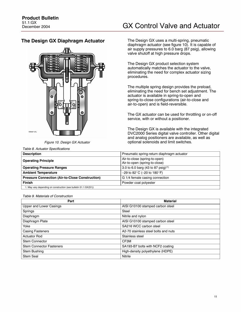
The Design GX Diaphragm Actuator
W8487-3/IL
Figure 10. Design GX Actuator
The Design GX uses a multi-spring, pneumaticdiaphragm actuator (see figure 10). It is capable ofair supply pressures to 6.0 barg (87 psig), allowingvalve shutoff at high pressure drops.
The Design GX product selection systemautomatically matches the actuator to the valve,eliminating the need for complex actuator sizingprocedures.
The multiple spring design provides the preload,eliminating the need for bench set adjustment. Theactuator is available in spring-to-open andspring-to-close configurations (air-to-close andair-to-open) and is field-reversible.
The GX actuator can be used for throttling or on-offservice, with or without a positioner.
The Design GX is available with the integratedDVC2000 Series digital valve controller. Other digitaland analog positioners are available, as well asoptional solenoids and limit switches.
Table 8. Actuator Specifications
Description Pneumatic spring-return diaphragm actuator
Operating Principle Air-to-close (spring-to-open)Air-to-open (spring-to-close)
Operating Pressure Ranges 3.0 to 6.0 barg (43 to 87 psig)(1)
Ambient Temperature –29 to 82�C (–20 to 180�F)
Pressure Connection (Air-to-Close Construction) G 1/4 female casing connection
Finish Powder coat polyester1. May vary depending on construction (see bulletin 51.1:GX(S1))
Table 9. Materials of Construction
Part Material
Upper and Lower Casings AISI G10100 stamped carbon steel
Springs Steel
Diaphragm Nitrile and nylon
Diaphragm Plate AISI G10100 stamped carbon steel
Yoke SA216 WCC carbon steel
Casing Fasteners A2-70 stainless steel bolts and nuts
Actuator Rod Stainless steel
Stem Connector CF3M
Stem Connector Fasteners SA193-B7 bolts with NCF2 coating
Stem Bushing High-density polyethylene (HDPE)
Stem Seal Nitrile

GX Control Valve and ActuatorProduct Bulletin
51.1:GXDecember 2004
12
Actuator SelectionWith the Design GX, actuator selection has neverbeen easier. Once the valve size and port diameterhave been determined, the actuator is automaticallyselected. No spring selection or bench setcalculations are required.
The following tables provide the maximum allowable
pressure drops for the Design GX (see tables 10 and11). The majority of GX constructions (bothair-to-open and air-to-close) are rated to a fullpressure class shutoff capability of 51.7 bar (750 psi)for a 4 to 6 bar (58 to 87 psig) actuator air supply.(For Hastelloy C trim or actuator air supplypressures of less than 4 bar (58 psig), refer to Fisherbulletin 51.1:GX (S1) for additional information.)
Table 10. Actuator Pressure Drop Capability For 316L Trim (with 316L or Nitronic 50 stem) in Standard, Extension, and BellowsBonnet Constructions with 4-6 bar (58-87 psi) Actuator Air Supply(1, 2, 3)
VALVE SIZE PORT SIZE(mm)
TRIM STYLE SHUTOFF CAPABILITY
DN15 to DN100 (0.5 to 4 Inch) 4.8 to 46 Unbalanced Full Pressure Class �P(4)
DN80 to DN100 (3 to 4 Inch) 70 to 90 Balanced Full Pressure Class �P(4)
DN80 to DN100 (3 to 4 Inch) 70 to 90 Unbalanced See table 111. For both air-to-open and air-to-close constructions. Some air-to-close actuator air supply restrictions exist. See Fisher bulletin 51.1:GX (S1) for additional information.2. For Hastelloy C trim or supply pressures less than 4 bar (58 psi), see Fisher bulletin 51.1:GX (S1) for additional information.3. Applies to both PTFE and Graphite ULF packing.4. Actuator is capable to 51.7 bar (750 psi) pressure drop. Some air-to-close actuator air supply restrictions exist. See Fisher bulletin 51.1:GX (S1) for additional information.
Table 11. Size 1200 Actuator Pressure Drop Capability For Unbalanced 316L Trim (with 316L or Nitronic 50 stem) in Standard andExtension Bonnet Constructions at 4-6 bar (58-87 psi) Supply(1)
MAXIMUM ALLOWABLE PRESSURE DROP
Port SizeAir-to-Open
Air-to-Close
Valve Size Bonnet StylePort Size
Packing 3-6 bar(44-87 psi)
4 bar (58 psi)
5 bar (73 psi)
6 bar (87 psi) Maximum Pressure Drop @
Maximum Actuator Supplymm
Bar(psi)
Bar(psi)
Bar(psi)
Bar(psi)
Maximum Actuator SupplyPressure
DN80 / Standard 70
GraphiteULF
32.6(472)
51.7(750)
- - -51.7 bar @ 5.6 bar supply maxDN80 /
3 InchStandard 70
PTFE33.1(480)
51.7(750)
- - -
51.7 bar @ 5.6 bar supply max(750 psi @ 81 psi supply max)
70
GraphiteULF
32.6(472)
51.7(750)
- - -51.7 bar @ 5.6 bar supply max
DN100 / Standard
70PTFE
33.1(480)
51.7(750)
- - -
51.7 bar @ 5.6 bar supply max(750 psi @ 81 psi supply max)
DN100 / 4 Inch
Standard
90
GraphiteULF
19.7(286)
28.5(414)
51.7(750)
- - -51.7 bar @ 5.6 bar supply max90
PTFE20.0(290)
28.8(418)
51.7(750)
- - -
51.7 bar @ 5.6 bar supply max(750 psi @ 81 psi supply max)
DN80 / Extension 70
GraphiteULF
32.6(472)
51.7(750)
- - - - - -51.7 bar @ 4.2 bar supply maxDN80 /
3 InchExtension 70
PTFE33.1(480)
51.7(750)
- - - - - -
51.7 bar @ 4.2 bar supply max(750 psi @ 61 psi supply max)
70
GraphiteULF
32.6(472)
51.7(750)
- - - - - -51.7 bar @ 4.2 bar supply max
DN100 / Extension
70PTFE
33.1(480)
51.7(750)
- - - - - -
51.7 bar @ 4.2 bar supply max(750 psi @ 61 psi supply max)
DN100 / 4 Inch
Extension
90
GraphiteULF
19.7(286)
28.5(414)
- - - - - -32.1 bar @ 4.2 bar supply max(466 psi @ 61 psi supply max)
90PTFE
20.0(290)
28.8(418)
- - - - - -32.5 bar @ 4.2 bar supply max(471 psi @ 61 psi supply max)
1. For Hastelloy C trim or supply pressures less than 4 bar (58 psi), see Fisher bulletin 51.1:GX (S1) additional information.

GX Control Valve and ActuatorProduct Bulletin51.1:GXDecember 2004
13
Bellows Extension Bonnet
The Design GX bellows extension bonnet providesreliable and tight stem sealing for those applicationswhere emissions escaping to the environmentcannot be tolerated (see figure 11). The GX bellowsis available in SST (1.4571 / 316Ti) or HastelloyC276 and covers a full range of valve sizes (seetables 12 and 13).
The GX bellows system has been designedfor 100,000 full-travel cycles at maximumallowable pressure and ambient temperature(20�C [68�F]).
The mechanically-formed metal bellows provideshigh operating reliability and extended cycle life (seetables 14, 15, and 16 for details).
The GX bellows design incorporates a ruggeddouble- or triple-wall construction for added security.Each bellows has been tested with helium before itleaves the factory.
The GX bellows bonnet comes standard with alive-loaded, PTFE packing system as a securitybackup. A connection is provided above the bellowsto allow purging or monitoring the integrity of thereplaceable bellows.
W8958-1
PACKINGFOLLOWER
BONNET
LIVE-LOADEDPTFE PACKING
BODY/BONNETGASKET
PURGE / MONITORINGCONNECTION
BELLOWS NUT
BELLOWSGASKET
BELLOWS/STEMASSEMBLY
EXTENSIONBONNET
BUSHING
VALVE PLUG
Step 1Size and select the Design GX control valve thatis appropriate for the application. This willidentify the:
� Valve body size� Actuator size� Orifice size�Trim style (balanced or unbalanced)� Valve body material
Step 4Using table 10 or bulletin 51.1:GX(S1), verify theapplication pressure drop does not exceed theactuator capability.
Step 2Confirm bellows availability from table 12.
Step 3Using table 13. select the bellows materialcombination that is appropriate for theapplication. Using the temperature limits shownin table 7, confirm the selected construction isappropriate for the application temperatures.
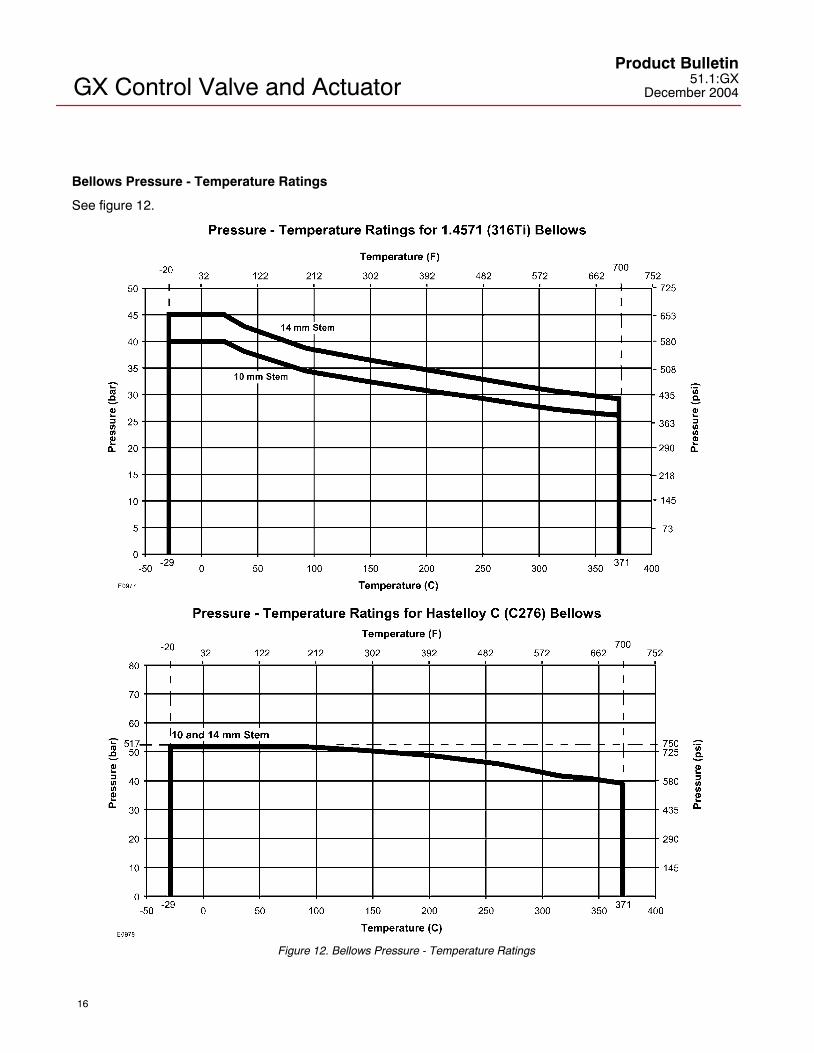
Step 5Using figure 12, check to ensure the maximumprocess pressure and temperature do not exceedthe pressure-temperature rating of the selectedbellows.
Bellows Selection ProcessFollow this process to assist in selecting
the appropriate bellows for the application.
Figure 11. Design GX Bellows Bonnet and Selection Process

GX Control Valve and ActuatorProduct Bulletin
51.1:GXDecember 2004
14
Table 12. GX Constructions with Bellows Availability
VALVE BODY SIZES PORT SIZE(mm)
ACTUATOR SIZES PLUG TRAVEL TRIM STYLE
DN15-50 (0.5 to 2-Inch)
4.8 to 46 225 and 750 20 mm Unbalanced
DN80 36 to 46 750 20 mm UnbalancedDN80(3-Inch) 70 750 20 mm Balanced
DN100 46 750 20 mm UnbalancedDN100 (4-Inch) 90 750 20 mm Balanced
Table 13. Bellows Extension Materials of Construction
Valve Body /Extension Bellows
BellowStem
Trim Materials
Bolting Packing Gaskets Lower BushingMonitoringConnectionExtension
BonnetBellows Stem
Extension PlugStem
Material
Bolting Packing Gaskets Lower Bushing ConnectionPlug
SST(1.4571/316Ti)
316L 316L 316LSA193-B7with NCF2
coating
Live-loadedPTFE
Graphitelaminate
316L withUltimet
(R31233) insert316L
Carbon Steel(1.0619/WCC)
HastelloyC276
316L 316L 316LSA193-B7with NCF2
coating
Live-loadedPTFE
Graphitelaminate
316L withUltimet
(R31233) insert316L
HastelloyC276
HastelloyC22
Hastelloy C Hastelloy CNitronic 50
(XM-19)Live-loaded
PTFE
PTFEencapsulatedHastelloy C
Hastelloy C withUltimet
(R31233) insert
HastelloyC276
SST(1.4571/316Ti)
316L 316L 316LNitronic 50
(XM-19)Live-loaded
PTFEGraphitelaminate
316L withUltimet
(R31233) insert316L
Stainless Steel(1.4409/CF3M)
HastelloyC276
316L 316L 316LNitronic 50
(XM-19)Live-loaded
PTFEGraphitelaminate
316L withUltimet
(R31233) insert316L
HastelloyC276
HastelloyC22
Hastelloy C Hastelloy CNitronic 50
(XM-19)Live-loaded
PTFE
PTFEencapsulatedHastelloy C
Hastelloy C withUltimet
(R31233) insert
HastelloyC276
Hastelloy C(CW2M)
HastelloyC276
HastelloyC22
Hastelloy C Hastelloy CNitronic 50
(XM-19)Live-loaded
PTFE
PTFEencapsulatedHastelloy C
Hastelloy C withUltimet
(R31233) insert
HastelloyC276
For bellows height dimensions, see table 18.

GX Control Valve and ActuatorProduct Bulletin51.1:GXDecember 2004
15
Cycle Life
Bellows service life is affected by several factors, including process pressure, temperature, and plug travel.Tables 14, 15, 16, and 17 provide estimates of cycle life for several cases.
Table 14. Estimated Bellows Cycle Life at 10.3 bar (150 psig) and 20�C (68�F)
VALVE SIZE STEMSIZE
BELLOWSMATERIAL
PLYS BELLOWSPRESSURE
PROCESSTEMPERATURE ESTIMATED CYCLE LIFE
(50% Stroke [25 75% travel])VALVE SIZE
SIZE MATERIALPLYS
PRESSURE�C �F
(50% Stroke [25-75% travel])
DN15-50 10mm
1.4571 (316Ti) 2 10.3 bar (150 psig)
20 68 1,040,000DN15 50
(0.5 to 2-Inch) 10mmHastelloy C276 3 10.3 bar
(150 psig)20 68 910,000
DN80-100 14mm
1.4571 (316Ti) 2 10.3 bar (150 psig)
20 68 1,020,000DN80 100
(3 to 4-Inch) 14mmHastelloy C276 2 10.3 bar
(150 psig)20 68 980,000
Table 15. Estimated Bellows Cycle Life at Bellows Maximum Allowable Pressure and 20�C (68�F)
VALVE SIZE STEMSIZE
BELLOWSMATERIAL
PLYS
MAXIMUMALLOWABLE
BELLOWS
PROCESSTEMPERATURE ESTIMATED CYCLE LIFE
(50% Stroke [25 75% travel])VALVE SIZE
SIZE MATERIALPLYS
BELLOWSPRESSURE(1) �C �F
(50% Stroke [25-75% travel])
DN15-50 10mm
1.4571 (316Ti) 2 40 bar (580 psig)
20 68 830,000DN15 50
(0.5 to 2-Inch) 10mmHastelloy C276 3 51.7 bar
(750 psig)20 68 800,000
DN80-100 14mm
1.4571 (316Ti) 2 45 bar (650 psig)
20 68 800,000DN80 100
(3 to 4-Inch) 14mmHastelloy C276 2 51.7 bar
(750 psig)20 68 810,000
1. Valve maximum allowable pressure drop may be limited by size and material. See GX bulletin 51.1:GX(S1) for additional information.
Table 16. Estimated Bellows Cycle Life at Bellows Maximum Allowable Pressure and 232�C (450�F)
VALVE SIZE STEMSIZE
BELLOWSMATERIAL
PLYS
MAXIMUMALLOWABLE
BELLOWS
PROCESSTEMPERATURE ESTIMATED CYCLE LIFE
(50% Stroke [25 75% travel])VALVE SIZE
SIZE MATERIALPLYS
BELLOWSPRESSURE(1) �C �F
(50% Stroke [25-75% travel])
DN15-50 10mm
1.4571 (316Ti) 2 29.8 bar (430 psig)
232 450 410,000DN15 50
(0.5 to 2-Inch) 10mmHastelloy C276 3 47.2 bar
(685 psig)232 450 560,000
DN80-100 14mm
1.4571 (316Ti) 2 33.5 bar (485 psig)
232 450 390,000DN80 100
(3 to 4-Inch) 14mmHastelloy C276 2 47.2 bar
(685 psig)232 450 550,000
1. Valve maximum allowable pressure drop may be limited by size and material. See GX bulletin 51.1:GX(S1) for additional information.
Table 17. Estimated Bellows Cycle Life at Bellows Maximum Allowable Pressure and 371�C (700�F)
VALVE SIZE STEMSIZE
BELLOWSMATERIAL
PLYS
MAXIMUMALLOWABLE
BELLOWS
PROCESSTEMPERATURE ESTIMATED CYCLE LIFE
(50% Stroke [25 75% travel])VALVE SIZE
SIZE MATERIALPLYS
BELLOWSPRESSURE �C �F
(50% Stroke [25-75% travel])
DN15-50 10mm
1.4571 (316Ti) 2 26.1 bar (380 psig)
371 700 250,000DN15 50
(0.5 to 2-Inch) 10mmHastelloy C276 3 39.3 bar
(570 psig)371 700 430,000
DN80-100 14mm
1.4571 (316Ti) 2 29.3 bar (425 psig)
371 700 240,000DN80 100
(3 to 4-Inch) 14mmHastelloy C276 2 39.3 bar
(570 psig)371 700 430,000
GX Control Valve and ActuatorProduct Bulletin
51.1:GXDecember 2004
16
Bellows Pressure - Temperature Ratings
See figure 12.
Figure 12. Bellows Pressure - Temperature Ratings

GX Control Valve and ActuatorProduct Bulletin51.1:GXDecember 2004
17
Valve-Actuator Dimensions and WeightsSee figure 13 and table 18.
E
D
AR
A/2
A
F
C
GE03755_4_3
Figure 13. Design GX Dimensions (also see table 18)Table 18. Design GX Dimensions and Weights
A C D TOTAL WEIGHT
VALVESIZE
PORTDIA ACTUATOR
SIZEPN10 -PN40
ANSIClass150
ANSIClass300
StdBonnet
Extensionor
BellowsBonnet
ActuatorHeight
(StandardBonnet)
ActuatorHeight
(Extensionor Bellows
Bonnet)
ECasing
Dia
F (AR)RemovalHeight(3)
WithStandardBonnet
WithExtensionor Bellows
Bonnet
mm mm mm mm mm mm mm mm mm mm kg kg
DN 15/0.5 Inch
4.89.5
225225
130130
184184
190190
6666
304304
313313
313313
270270
115115
2121
2525
DN 20/0.75 Inch
4.89.514
225225225
150150150
184184184
194194194
666666
304304304
313313313
313313313
270270270
115115115
222222
262626
DN 25/1-Inch
4.89.51422
225225225225
160160160160
184184184184
197197197197
58585858
296296296296
313313313313
313313313313
270270270270
115115115115
22222222
26262626
DN 40/1.5 Inch
142236
225225750
200200200
222222222
235235235
626262
300300300
313313342
313313342
270270430
115115115
252552
292956
DN 50/2-Inch
223646
225750750
230230230
254254254
267267267
686868
306306306
313342342
313342342
270430430
115115115
295656
336060
DN 80/3-Inch
3646
70(1)
70
750750750
1200
310310310310
298298298298
318318318318
105105105105
373373
373(4)
373
375375375458
375375375458
430430430566
125125125125
797981
131
8888
NA(4)
140
DN 100/4-Inch
4670
90(2)
90(1)
90
7501200750750
1200
350350350350350
352352352352352
368368368368368
121121121121121
393393
393(4)
393(4)
393
379462379379462
375458375375458
430566430430566
130130130130130
98150105105150
109161
NA(4)
NA(4)
161
1. Balanced trim design.2. Balanced trim with reduced-capacity plug.3. Clearance required for removing actuator from installed valve body.4. Bellows bonnets are available for these constructions. However, extension bonnets are not available with balanced trim due to temperature limitations of the trim seals.

GX Control Valve and ActuatorProduct Bulletin
51.1:GXDecember 2004
18
Table 19. Positioner Selection Guidelines
Type Digital I/P(1) I/P(2) P/P(3) IntrinsicSafety(4)
Flameproof /Explosionproof(4) Non- Incendive(4)
DVC2000 X X XDVC6030 X X X X3582i X X X X3661 X X X3660 X
1. Digital I/P - microprocessor based electro-pneumatic with HART communication.2. I/P - electro-pneumatic3. P/P - pneumatic4. Refer to Fisher bulletins 9.2:001 and 9.2:002 for instrument hazardous area classification details.
Design GX Actuator Accessories
The Design GX is available with a variety ofpneumatic (P/P), electro-pneumatic (I/P), and digitalvalve positioners, as well as limit switches andsolenoids. Table 19 provides the basic features ofthe positioners offered with the Design GX actuator.
The FIELDVUE DVC2000 Series DigitalValve Controller
The DVC2000 Series digital valve controller (figure14) is simple to use, compact, and designed for theGX control valve. It converts a 4-20mA input signalinto a pneumatic output signal, which feeds thecontrol valve actuator. Instrument setup is performedwith a pushbutton and liquid crystal display (LCD)interface. This interface is protected from theenvironment within an IP66 enclosure. Multiplelanguages are supported with the local interfaceincluding German, French, Italian, Spanish, Chinese,Japanese, and English. Additionally, HART�communication is supported over the 4-20mA loopwiring.
The DVC2000 is designed to be integrally mountedto the Design GX actuator, avoiding the need formounting brackets. The DVC2000 mounts directly toan interface pad on the actuator yoke leg with asecure 3-point mounting. An internal passage insidethe yoke leg transmits the pneumatic signal to theactuator casing, eliminating the need for externaltubing (in the air-to-open configuration).
W8755
Figure 14. FIELDVUE DVC2000 Series Digital ValveController
The high-performance linkage-less positionfeedback system eliminates physical contactbetween the valve stem and the positioner. Thereare no wearing parts so cycle life is maximized.Additionally, the elimination of levers and linkagesreduces the number of mounting parts and themounting complexity. Positioner replacement andmaintenance is simplified because the feedbackparts stay connected to the actuator.
The DVC2000 Series is available with an optionalmodule which includes two (2) integral limit switchesand a stem position transmitter. The limit switchesare configurable for open and closed valveindication. The position transmitter provides a4-20mA signal for valve position feedbackverification. As an integral component to theinstrument, this option module avoids the need fordifficult-to-mount external switches and transmitters.
Designed to meet intrinsic safety and non-incendiverequirements, this instrument delivers scalablefunctionality and high performance in a smallpackage.
GX Control Valve and ActuatorProduct Bulletin51.1:GXDecember 2004
19
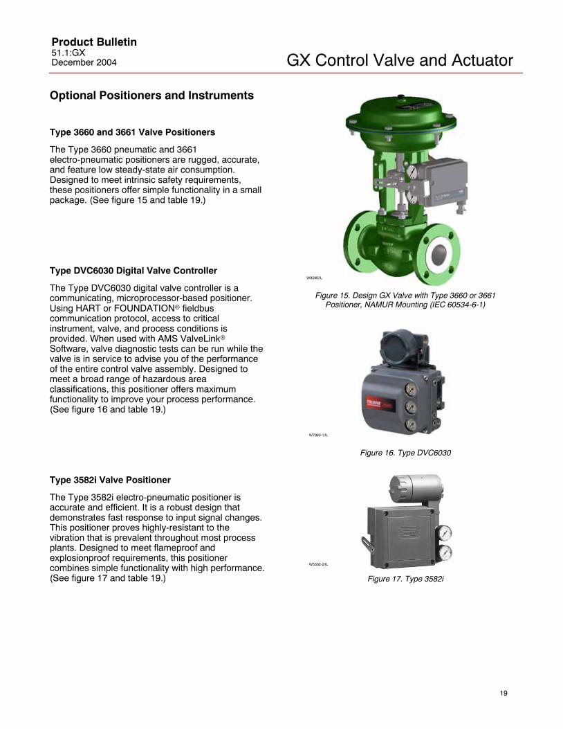
Optional Positioners and Instruments
Type 3660 and 3661 Valve Positioners
The Type 3660 pneumatic and 3661electro-pneumatic positioners are rugged, accurate,and feature low steady-state air consumption.Designed to meet intrinsic safety requirements,these positioners offer simple functionality in a smallpackage. (See figure 15 and table 19.)
Type DVC6030 Digital Valve Controller
The Type DVC6030 digital valve controller is acommunicating, microprocessor-based positioner.Using HART or FOUNDATION� fieldbuscommunication protocol, access to criticalinstrument, valve, and process conditions isprovided. When used with AMS ValveLink�Software, valve diagnostic tests can be run while thevalve is in service to advise you of the performanceof the entire control valve assembly. Designed tomeet a broad range of hazardous areaclassifications, this positioner offers maximumfunctionality to improve your process performance.(See figure 16 and table 19.)
Type 3582i Valve Positioner
The Type 3582i electro-pneumatic positioner isaccurate and efficient. It is a robust design thatdemonstrates fast response to input signal changes.This positioner proves highly-resistant to thevibration that is prevalent throughout most processplants. Designed to meet flameproof andexplosionproof requirements, this positionercombines simple functionality with high performance.(See figure 17 and table 19.)
W8590/IL
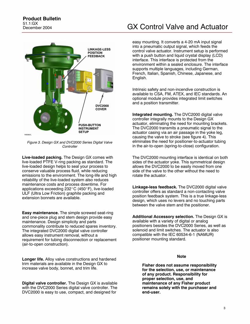
Figure 15. Design GX Valve with Type 3660 or 3661Positioner, NAMUR Mounting (IEC 60534-6-1)
W7963-1/IL
Figure 16. Type DVC6030
W5502-2/IL
Figure 17. Type 3582i

GX Control Valve and ActuatorProduct Bulletin
51.1:GXDecember 2004
20
Manual Handwheels
The Design GX is available with an optional,side-mounted manual handwheel (see figure 18).These handwheels provide a robust method ofmanually operating the valve in an emergency orupon loss of instrument air.
The GX handwheel will stroke the valve up to 20mmtravel, and is available on the size 225 and 750
actuators. Dimensions are provided in figure 19 andtable 20.
When mounted to an air-to-close (spring-to-open)actuator, rotating the handwheel clockwise movesthe stem downwards. When mounted to anair-to-open (spring-to-close) actuator, turning thehandwheel in the clockwise direction causes thestem to move upwards. Disengagement of thehandwheel to allow automatic operation isaccomplished by simply rewinding the handwheel.
W9025
Figure 18. Design GX Control Valve and Actuator System with Manual Handwheel

GX Control Valve and ActuatorProduct Bulletin51.1:GXDecember 2004
21
E0975
A1A2
A1A2
C1
C2
� B
� B
Figure 19. Design GX with Handwheel Dimensions (also see table 20)
Table 20. Design GX with Handwheel Dimensions and WeightsVALVE SIZE
ACTUATORVALVE HANDWHEEL A1 A2 B C1(1) C2(2)
ENANSI ACTUATOR
SIZE
VALVETRAVEL
HANDWHEELWEIGHT
A1 A2 B C1(1) C2(2)
ENInches
SIZEmm kg mm mm mm mm mm
DN 15 0.5 225 20 5.6 215 242 223 159 60
DN 20 0.75 225 20 5.6 215 242 223 159 60
DN 25 1 225 20 5.6 215 242 223 159 60
DN 40 1.5 225750
2020
5.612.2
215293
242317
223356
159159
6060
DN 50 2 225750
2020
5.612.2
215293
242317
223356
159159
6060
DN 80 3 750 20 12.2 293 317 356 169 70
DN 100 4 750 20 12.2 293 317 356 173 741. C1 is Air-to-Open, Spring-to-Close.2. C2 is Air-to-Close, Spring-to-Open.

GX Control Valve and ActuatorProduct Bulletin
51.1:GXDecember 2004
22
CoefficientsTable 21. Design GX, Equal Percentage Valve Plug, Flow Up Through the Port
Equal Percentage - Flow Up Equal PercentageCharacteristic
ValveSize
PortDiameter
MaximumTravel
FlowCoeffi-
Valve Opening—Percent of Total TravelFL
(1)Size
mm mmCoeffi-cient 10 20 30 40 50 60 70 80 90 100
FL( )
Cv 0.133 0.222 0.347 0.501 0.699 1.04 1.50 2.15 2.98 3.57 0.95
9 5 20Kv 0.115 0.192 0.300 0.433 0.605 0.900 1.29 1.86 2.58 3.09 - - -
9.5 20XT 0.77 0.68 0.65 0.61 0.55 0.55 0.58 0.55 0.59 0.68 - - -
DN 15 (0 5 Inch)Fd 0.11 0.13 0.16 0.19 0.22 0.28 0.34 0.44 0.58 0.80 - - -
DN 15 (0.5 Inch)Cv 0.0613 0.0838 0.131 0.184 0.269 0.375 0.543 0.750 1.05 1.51 0.95
9 5(2) 20Kv 0.0530 0.0724 0.113 0.159 0.233 0.324 0.470 0.649 0.912 1.31 - - -
9.5(2) 20XT 1.0 0.89 0.75 0.68 0.64 0.62 0.60 0.58 0.58 0.54 - - -
Fd 0.09 0.09 0.09 0.11 0.13 0.14 0.20 0.24 0.28 0.35 - - -
Cv 0.139 0.186 0.315 0.511 0.776 1.23 1.97 3.28 5.35 6.89 0.97
14 20Kv 0.120 0.161 0.272 0.442 0.671 1.07 1.70 2.84 4.63 5.96 - - -
14 20XT 0.78 0.71 0.59 0.59 0.58 0.51 0.57 0.51 0.67 0.81 - - -
Fd 0.08 0.08 0.10 0.13 0.16 0.20 0.26 0.33 0.47 0.59 - - -
Cv 0.133 0.222 0.347 0.501 0.699 1.04 1.50 2.15 2.98 3.57 0.95
DN 20 (0 75 Inch) 9 5 20Kv 0.115 0.192 0.300 0.433 0.605 0.900 1.29 1.86 2.58 3.09 - - -
DN 20 (0.75 Inch) 9.5 20XT 0.77 0.68 0.65 0.61 0.55 0.55 0.58 0.55 0.59 0.68 - - -
Fd 0.11 0.13 0.16 0.19 0.22 0.28 0.34 0.44 0.58 0.80 - - -
Cv 0.0613 0.0838 0.131 0.184 0.269 0.375 0.543 0.750 1.05 1.51 0.95
9 5(2) 20Kv 0.0530 0.0724 0.113 0.159 0.233 0.324 0.470 0.649 0.912 1.31 - - -
9.5(2) 20XT 1.0 0.89 0.75 0.68 0.64 0.62 0.60 0.58 0.58 0.54 - - -
Fd 0.09 0.09 0.09 0.11 0.13 0.14 0.20 0.24 0.28 0.35 - - -1. At 100% travel.2. Restricted trim.3. Balanced trim.4. Balanced, restricted trim.
-continued-

GX Control Valve and ActuatorProduct Bulletin51.1:GXDecember 2004
23
Table 21. Design GX, Equal Percentage Valve Plug, Flow Up Through the Port (continued)
Equal Percentage - Flow Up Equal PercentageCharacteristic
ValveSize
PortDiameter
MaximumTravel
FlowCoeffi-
Valve Opening—Percent of Total TravelFL
(1)Size
mm mmCoeffi-cient 10 20 30 40 50 60 70 80 90 100
FL( )
Cv 0.673 0.937 1.32 1.89 2.25 3.13 5.05 7.39 10.5 13.7 0.93
22 20Kv 0.582 0.810 1.14 1.63 1.94 2.71 4.36 6.39 9.05 11.9 - - -
22 20XT 0.61 0.59 0.58 0.57 0.74 0.82 0.64 0.58 0.68 0.77 - - -
Fd 0.09 0.11 0.13 0.15 0.18 0.21 0.25 0.31 0.39 0.49 - - -
Cv 0.139 0.186 0.315 0.511 0.776 1.23 1.97 3.28 5.35 6.89 0.97
14 20Kv 0.120 0.161 0.272 0.442 0.671 1.07 1.70 2.84 4.63 5.96 - - -
14 20XT 0.78 0.71 0.59 0.59 0.58 0.51 0.57 0.51 0.67 0.81 - - -
DN 25 (1 Inch)Fd 0.08 0.08 0.10 0.13 0.16 0.20 0.26 0.33 0.47 0.59 - - -
DN 25 (1-Inch)Cv 0.133 0.222 0.347 0.501 0.699 1.04 1.50 2.15 2.98 3.57 0.95
9 5 20Kv 0.115 0.192 0.300 0.433 0.605 0.900 1.29 1.86 2.58 3.09 - - -
9.5 20XT 0.77 0.68 0.65 0.61 0.55 0.55 0.58 0.55 0.59 0.68 - - -
Fd 0.11 0.13 0.16 0.19 0.22 0.28 0.34 0.44 0.58 0.80 - - -
Cv 0.0613 0.0838 0.131 0.184 0.269 0.375 0.543 0.750 1.05 1.51 0.95
9 5(2) 20Kv 0.0530 0.0724 0.113 0.159 0.233 0.324 0.470 0.649 0.912 1.31 - - -
9.5(2) 20XT 1.0 0.89 0.75 0.68 0.64 0.62 0.60 0.58 0.58 0.54 - - -
Fd 0.09 0.09 0.09 0.11 0.13 0.14 0.20 0.24 0.28 0.35 - - -
Cv 1.01 1.91 2.74 4.24 6.13 8.25 11.5 16.7 22.0 27.2 0.94
36 20Kv 0.874 1.65 2.37 3.67 5.30 7.14 9.95 14.4 19.0 23.5 - - -
36 20XT 0.87 0.93 0.91 0.80 0.89 0.86 0.76 0.79 0.82 0.78 - - -
Fd 0.64 0.80 0.87 0.54 0.55 0.50 0.41 0.40 0.43 0.45 - - -
Cv 0.591 0.850 1.20 1.79 2.51 3.50 4.93 7.07 11.0 14.3 0.93
DN 40 (1 5 Inch) 22 20Kv 0.511 0.735 1.04 1.55 2.17 3.03 4.26 6.12 9.52 12.4 - - -
DN 40 (1.5 Inch) 22 20XT 0.53 0.51 0.53 0.45 0.45 0.49 0.42 0.47 0.57 0.71 - - -
Fd 0.09 0.11 0.13 0.15 0.18 0.21 0.25 0.31 0.39 0.49 - - -
Cv 0.103 0.141 0.254 0.440 0.689 1.11 1.84 3.12 5.12 6.87 0.97
14 20Kv 0.0891 0.122 0.220 0.381 0.596 0.960 1.59 2.70 4.43 5.94 - - -
14 20XT 1.00 0.80 0.68 0.67 0.60 0.54 0.55 0.52 0.64 0.77 - - -
Fd 0.08 0.08 0.10 0.13 0.16 0.20 0.26 0.33 0.47 0.59 - - -
Cv 1.08 1.75 3.75 6.04 9.5 14.9 21.8 30.9 37.7 43.7 0.91
46 20Kv 0.931 1.51 3.24 5.22 8.20 12.9 18.9 26.7 32.6 37.8 - - -
46 20XT 0.73 0.70 0.79 0.81 0.78 0.81 0.76 0.71 0.82 0.85 - - -
Fd 0.70 0.84 0.47 0.48 0.40 0.36 0.37 0.40 0.43 0.45 - - -
Cv 1.08 2.01 2.80 4.26 6.31 8.38 11.6 17.2 23.1 28.6 0.93
DN 50 (2 Inch) 36 20Kv 0.931 1.74 2.42 3.69 5.45 7.25 10.0 14.9 20.0 24.7 - - -
DN 50 (2-Inch) 36 20XT 0.71 0.79 0.86 0.81 0.79 0.79 0.73 0.69 0.75 0.75 - - -
Fd 0.64 0.80 0.87 0.54 0.55 0.50 0.41 0.40 0.43 0.45 - - -
Cv 0.601 0.869 1.23 1.77 2.50 3.46 4.49 6.62 10.2 13.5 0.96
22 20Kv 0.519 0.752 1.06 1.53 2.17 2.99 3.88 5.73 8.80 11.7 - - -
22 20XT 0.71 0.68 0.61 0.62 0.60 0.60 0.57 0.45 0.60 0.71 - - -
Fd 0.09 0.11 0.13 0.15 0.18 0.21 0.25 0.31 0.39 0.49 - - -1. At 100% travel.2. Restricted trim.3. Balanced trim.4. Balanced, restricted trim.
-continued-

GX Control Valve and ActuatorProduct Bulletin
51.1:GXDecember 2004
24
Table 21. Design GX, Equal Percentage Valve Plug, Flow Up Through the Port (continued)
Equal Percentage - Flow Up Equal PercentageCharacteristic
ValveSize
PortDiameter
MaximumTravel
FlowCoeffi-
Valve Opening—Percent of Total TravelFL
(1)Size
mm mmCoeffi-cient 10 20 30 40 50 60 70 80 90 100
FL( )
Cv 2.38 6.92 11.5 16.4 22.4 31.9 46.5 63.6 80.6 95.1 0.94
70 40Kv 2.06 5.99 9.95 14.2 19.4 27.6 40.2 55.0 69.7 82.3 - - -
70 40XT 0.83 0.81 0.85 0.83 0.80 0.76 0.72 0.75 0.77 0.80 - - -
Fd 0.82 0.50 0.53 0.53 0.47 0.42 0.40 0.40 0.43 0.45 - - -
Cv 2.71 4.63 7.60 11.3 17.1 23.7 35.3 50.4 61.6 75.7 0.89
70(3) 20Kv 2.34 4.00 6.57 9.79 14.7 20.5 30.5 43.6 53.3 65.5 - - -
70(3) 20XT 0.54 0.50 0.49 0.51 0.51 0.57 0.51 0.50 0.64 0.68 - - -
DN 80 Fd 0.06 0.07 0.10 0.12 0.15 0.18 0.22 0.26 0.30 0.34 - - -DN 80(3-Inch) Cv 0.873 1.66 3.41 5.66 8.75 13.8 20.7 30.5 37.1 43.7 0.97( )
46 20Kv 0.755 1.44 2.95 4.90 7.57 11.9 17.9 26.4 32.1 37.8 - - -
46 20XT 0.75 0.82 0.75 0.82 0.77 0.73 0.78 0.70 0.85 0.88 - - -
Fd 0.70 0.84 0.47 0.48 0.40 0.36 0.37 0.40 0.43 0.45 - - -
Cv 0.799 1.78 2.65 4.01 6.02 7.61 10.8 16.3 23.4 27.5 0.96
36 20Kv 0.691 1.54 2.29 3.47 5.21 6.58 9.32 14.1 20.3 23.8 - - -
36 20XT 0.84 0.86 0.88 0.84 0.83 0.88 0.79 0.72 0.76 0.85 - - -
Fd 0.64 0.80 0.87 0.54 0.55 0.50 0.41 0.40 0.43 0.45 - - -
Cv 5.56 13.6 21.1 29.1 40.8 55.8 77.5 117 145 165 0.90
90 40Kv 4.81 11.7 18.3 25.1 35.3 48.3 67.0 101 126 143 - - -
90 40XT 0.93 0.93 0.94 0.90 0.85 0.82 0.82 0.75 0.78 0.80 - - -
Fd 0.39 0.49 0.52 0.48 0.45 0.44 0.33 0.36 0.39 0.41 - - -
Cv 5.88 9.43 13.1 17.5 27.3 42.4 63.4 85.5 107 128 0.87
90(3) 20Kv 5.09 8.16 11.3 15.1 23.6 36.7 54.8 74.0 92.6 111 - - -
90(3) 20XT 0.55 0.54 0.54 0.55 0.43 0.52 0.57 0.58 0.63 0.67 - - -
Fd 0.07 0.08 0.10 0.11 0.13 0.18 0.22 0.26 0.30 0.34 - - -
Cv 2.38 3.65 5.64 8.42 12.0 17.4 24.8 36.7 53.0 68.5 0.90
DN 10090(4) 20
Kv 2.06 3.16 4.88 7.28 10.4 15.1 21.5 31.7 45.8 59.3 - - -DN 100(4-Inch) 90(4) 20
XT 0.68 0.61 0.57 0.55 0.55 0.55 0.56 0.48 0.50 0.58 - - -( )
Fd 0.04 0.05 0.06 0.08 0.09 0.11 0.14 0.16 0.20 0.24 - - -
Cv 2.04 5.78 10.6 15.3 20.8 29.8 43.3 61.9 80.6 97.9 0.92
70 40Kv 1.76 5.00 9.17 13.2 18.0 25.8 37.5 53.5 69.7 84.5 - - -
70 40XT 0.79 0.83 0.85 0.85 0.82 0.77 0.73 0.73 0.75 0.76 - - -
Fd 0.82 0.50 0.53 0.53 0.47 0.42 0.40 0.40 0.43 0.45 - - -
Cv 1.02 1.76 3.58 5.76 8.85 14.1 21.4 30.6 37.9 44.0 0.94
46 20Kv 0.88 1.52 3.10 4.98 7.66 12.2 18.5 26.5 32.8 38.1 - - -
46 20XT 0.69 0.77 0.68 0.81 0.76 0.71 0.72 0.67 0.75 0.79 - - -
Fd 0.70 0.84 0.47 0.48 0.40 0.36 0.37 0.40 0.43 0.45 - - -1. At 100% travel.2. Restricted trim.3. Balanced trim.4. Balanced, restricted trim.

GX Control Valve and ActuatorProduct Bulletin51.1:GXDecember 2004
25
Table 22. Design GX, Linear Valve Plug, Flow Up Through the Port
Linear - Flow Up LinearCharacteristic
ValveSize
PortDiameter
MaximumTravel
FlowCoeffi-
Valve Opening—Percent of Total TravelFL
(1)Size
mm mmCoeffi-cient 10 20 30 40 50 60 70 80 90 100
FL( )
Cv 0.187 0.453 0.769 1.10 1.42 1.79 2.22 2.73 3.29 3.70 0.94
9 5 20Kv 0.161 0.392 0.665 0.952 1.23 1.55 1.92 2.36 2.85 3.20 - - -
9.5 20XT 0.59 0.56 0.55 0.53 0.58 0.57 0.60 0.58 0.63 0.63 - - -
Fd 0.12 0.18 0.24 0.29 0.34 0.39 0.45 0.53 0.65 0.80 - - -
Cv 0.0350 0.0805 0.140 0.210 0.291 0.371 0.455 0.539 0.627 0.700 0.94
4 8(4) 20Kv 0.0303 0.0696 0.121 0.182 0.251 0.321 0.394 0.466 0.542 0.606 - - -
4.8(4) 20XT 0.56 0.55 0.56 0.57 0.57 0.56 0.58 0.57 0.58 0.57 - - -
Fd 0.10 0.15 0.19 0.24 0.29 0.33 0.38 0.42 0.47 0.51 - - -
Cv 0.0356 0.0524 0.0736 0.0984 0.127 0.158 0.191 0.224 0.257 0.294 0.93
DN 154 8(4) 20
Kv 0.0308 0.0453 0.0637 0.0851 0.110 0.137 0.165 0.194 0.222 0.254 - - -DN 15(0.5 Inch)
4.8(4) 20XT 0.55 0.54 0.57 0.58 0.57 0.55 0.55 0.56 0.57 0.55 - - -( )
Fd 0.08 0.10 0.13 0.15 0.17 0.19 0.22 0.24 0.26 0.28 - - -
Cv 0.0437 0.0512 0.0597 0.0694 0.0806 0.0929 0.105 0.116 0.126 0.139 0.86
4 8(4) 20Kv 0.0378 0.0443 0.0516 0.0600 0.0697 0.0804 0.0908 0.100 0.109 0.120 - - -
4.8(4) 20XT 0.54 0.54 0.54 0.54 0.54 0.53 0.54 0.56 0.57 0.56 - - -
Fd 0.08 0.08 0.09 0.11 0.12 0.13 0.14 0.15 0.16 0.17 - - -
Cv 0.0037 0.0055 0.0085 0.0121 0.0163 0.0205 0.0246 0.0284 0.0326 0.0389 0.97
4 8(4) 20Kv 0.0032 0.0047 0.0073 0.0105 0.0141 0.0177 0.0213 0.0246 0.0282 0.0337 - - -
4.8(4) 20XT 1.00 0.94 0.81 0.76 0.68 0.64 0.60 0.59 0.60 0.58 - - -
Fd 0.05 0.06 0.06 0.07 0.07 0.08 0.09 0.09 0.10 0.11 - - -
Cv 0.685 1.46 2.28 3.05 3.81 4.56 5.42 6.34 7.21 7.80 0.96
14 20Kv 0.592 1.26 1.97 2.64 3.29 3.95 4.69 5.48 6.24 6.75 - - -
14 20XT 0.73 0.64 0.62 0.60 0.59 0.59 0.60 0.63 0.67 0.66 - - -
Fd 0.16 0.24 0.30 0.35 0.39 0.45 0.52 0.60 0.71 0.79 - - -
Cv 0.187 0.453 0.769 1.10 1.42 1.79 2.22 2.73 3.29 3.70 0.94
9 5 20Kv 0.161 0.392 0.665 0.952 1.23 1.55 1.92 2.36 2.85 3.20 - - -
9.5 20XT 0.59 0.56 0.55 0.53 0.58 0.57 0.60 0.58 0.63 0.63 - - -
Fd 0.12 0.18 0.24 0.29 0.34 0.39 0.45 0.53 0.65 0.80 - - -
Cv 0.0350 0.0805 0.140 0.210 0.291 0.371 0.455 0.539 0.627 0.700 0.94
4 8(4) 20Kv 0.0303 0.0696 0.121 0.182 0.251 0.321 0.394 0.466 0.542 0.606 - - -
DN 20
4.8(4) 20XT 0.56 0.55 0.56 0.57 0.57 0.56 0.58 0.57 0.58 0.57 - - -
DN 20(0 75
Fd 0.10 0.15 0.19 0.24 0.29 0.33 0.38 0.42 0.47 0.51 - - -(0.75Inch) Cv 0.0356 0.0524 0.0736 0.0984 0.127 0.158 0.191 0.224 0.257 0.294 0.93Inch)
4 8(4) 20Kv 0.0308 0.0453 0.0637 0.0851 0.110 0.137 0.165 0.194 0.222 0.254 - - -
4.8(4) 20XT 0.55 0.54 0.57 0.58 0.57 0.55 0.55 0.56 0.57 0.55 - - -
Fd 0.08 0.10 0.13 0.15 0.17 0.19 0.22 0.24 0.26 0.28 - - -
Cv 0.0437 0.0512 0.0597 0.0694 0.0806 0.0929 0.105 0.116 0.126 0.139 0.86
4 8(4) 20Kv 0.0378 0.0443 0.0516 0.0600 0.0697 0.0804 0.0908 0.100 0.109 0.120 - - -
4.8(4) 20XT 0.54 0.54 0.54 0.54 0.54 0.53 0.54 0.56 0.57 0.56 - - -
Fd 0.08 0.08 0.09 0.11 0.12 0.13 0.14 0.15 0.16 0.17 - - -
Cv 0.0037 0.0055 0.0085 0.0121 0.0163 0.0205 0.0246 0.0284 0.0326 0.0389 0.97
4 8(4) 20Kv 0.0032 0.0047 0.0073 0.0105 0.0141 0.0177 0.0213 0.0246 0.0282 0.0337 - - -
4.8(4) 20XT 1.00 0.94 0.81 0.76 0.68 0.64 0.60 0.59 0.60 0.58 - - -
Fd 0.05 0.06 0.06 0.07 0.07 0.08 0.09 0.09 0.10 0.11 - - -1. At 100% travel.2. Balanced trim.3. Balanced, restricted trim.4. Micro-Flow trim.
-continued-
GX Control Valve and ActuatorProduct Bulletin
51.1:GXDecember 2004
26
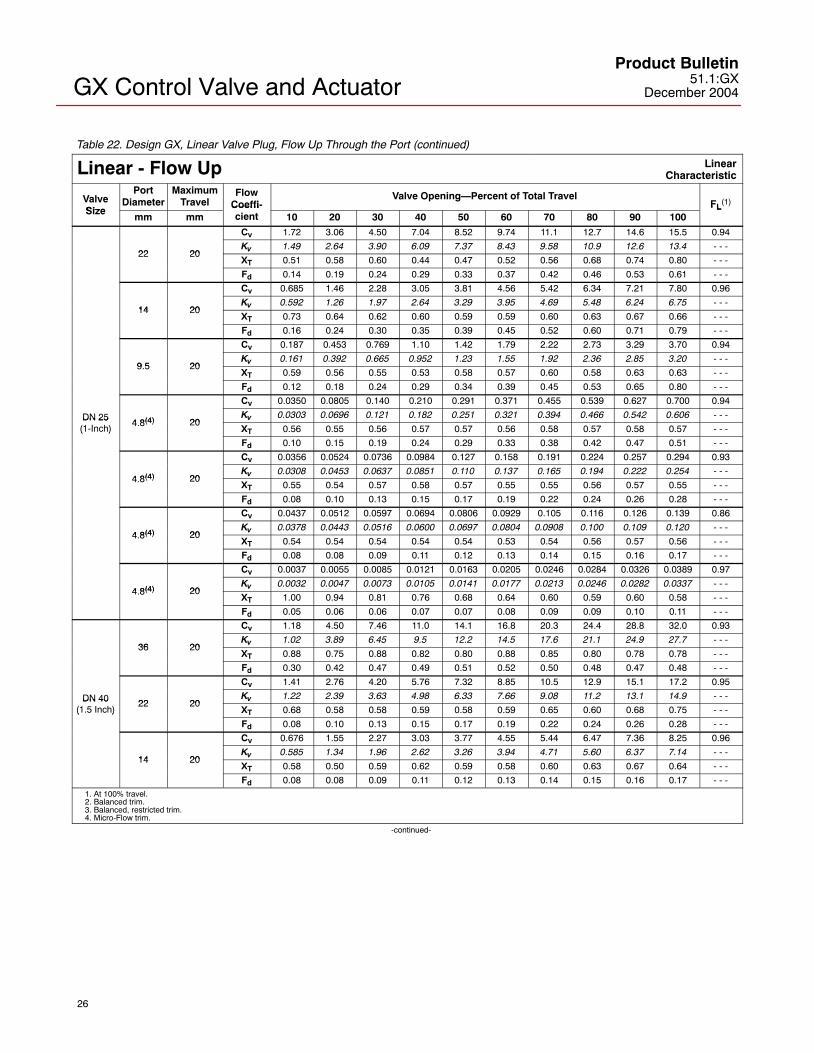
Table 22. Design GX, Linear Valve Plug, Flow Up Through the Port (continued)
Linear - Flow Up LinearCharacteristic
ValveSize
PortDiameter
MaximumTravel
FlowCoeffi-
Valve Opening—Percent of Total TravelFL
(1)Size
mm mmCoeffi-cient 10 20 30 40 50 60 70 80 90 100
FL( )
Cv 1.72 3.06 4.50 7.04 8.52 9.74 11.1 12.7 14.6 15.5 0.94
22 20Kv 1.49 2.64 3.90 6.09 7.37 8.43 9.58 10.9 12.6 13.4 - - -
22 20XT 0.51 0.58 0.60 0.44 0.47 0.52 0.56 0.68 0.74 0.80 - - -
Fd 0.14 0.19 0.24 0.29 0.33 0.37 0.42 0.46 0.53 0.61 - - -
Cv 0.685 1.46 2.28 3.05 3.81 4.56 5.42 6.34 7.21 7.80 0.96
14 20Kv 0.592 1.26 1.97 2.64 3.29 3.95 4.69 5.48 6.24 6.75 - - -
14 20XT 0.73 0.64 0.62 0.60 0.59 0.59 0.60 0.63 0.67 0.66 - - -
Fd 0.16 0.24 0.30 0.35 0.39 0.45 0.52 0.60 0.71 0.79 - - -
Cv 0.187 0.453 0.769 1.10 1.42 1.79 2.22 2.73 3.29 3.70 0.94
9 5 20Kv 0.161 0.392 0.665 0.952 1.23 1.55 1.92 2.36 2.85 3.20 - - -
9.5 20XT 0.59 0.56 0.55 0.53 0.58 0.57 0.60 0.58 0.63 0.63 - - -
Fd 0.12 0.18 0.24 0.29 0.34 0.39 0.45 0.53 0.65 0.80 - - -
Cv 0.0350 0.0805 0.140 0.210 0.291 0.371 0.455 0.539 0.627 0.700 0.94
DN 254 8(4) 20
Kv 0.0303 0.0696 0.121 0.182 0.251 0.321 0.394 0.466 0.542 0.606 - - -DN 25(1-Inch)
4.8(4) 20XT 0.56 0.55 0.56 0.57 0.57 0.56 0.58 0.57 0.58 0.57 - - -( )
Fd 0.10 0.15 0.19 0.24 0.29 0.33 0.38 0.42 0.47 0.51 - - -
Cv 0.0356 0.0524 0.0736 0.0984 0.127 0.158 0.191 0.224 0.257 0.294 0.93
4 8(4) 20Kv 0.0308 0.0453 0.0637 0.0851 0.110 0.137 0.165 0.194 0.222 0.254 - - -
4.8(4) 20XT 0.55 0.54 0.57 0.58 0.57 0.55 0.55 0.56 0.57 0.55 - - -
Fd 0.08 0.10 0.13 0.15 0.17 0.19 0.22 0.24 0.26 0.28 - - -
Cv 0.0437 0.0512 0.0597 0.0694 0.0806 0.0929 0.105 0.116 0.126 0.139 0.86
4 8(4) 20Kv 0.0378 0.0443 0.0516 0.0600 0.0697 0.0804 0.0908 0.100 0.109 0.120 - - -
4.8(4) 20XT 0.54 0.54 0.54 0.54 0.54 0.53 0.54 0.56 0.57 0.56 - - -
Fd 0.08 0.08 0.09 0.11 0.12 0.13 0.14 0.15 0.16 0.17 - - -
Cv 0.0037 0.0055 0.0085 0.0121 0.0163 0.0205 0.0246 0.0284 0.0326 0.0389 0.97
4 8(4) 20Kv 0.0032 0.0047 0.0073 0.0105 0.0141 0.0177 0.0213 0.0246 0.0282 0.0337 - - -
4.8(4) 20XT 1.00 0.94 0.81 0.76 0.68 0.64 0.60 0.59 0.60 0.58 - - -
Fd 0.05 0.06 0.06 0.07 0.07 0.08 0.09 0.09 0.10 0.11 - - -
Cv 1.18 4.50 7.46 11.0 14.1 16.8 20.3 24.4 28.8 32.0 0.93
36 20Kv 1.02 3.89 6.45 9.5 12.2 14.5 17.6 21.1 24.9 27.7 - - -
36 20XT 0.88 0.75 0.88 0.82 0.80 0.88 0.85 0.80 0.78 0.78 - - -
Fd 0.30 0.42 0.47 0.49 0.51 0.52 0.50 0.48 0.47 0.48 - - -
Cv 1.41 2.76 4.20 5.76 7.32 8.85 10.5 12.9 15.1 17.2 0.95
DN 40 22 20Kv 1.22 2.39 3.63 4.98 6.33 7.66 9.08 11.2 13.1 14.9 - - -DN 40
(1.5 Inch)22 20
XT 0.68 0.58 0.58 0.59 0.58 0.59 0.65 0.60 0.68 0.75 - - -( )
Fd 0.08 0.10 0.13 0.15 0.17 0.19 0.22 0.24 0.26 0.28 - - -
Cv 0.676 1.55 2.27 3.03 3.77 4.55 5.44 6.47 7.36 8.25 0.96
14 20Kv 0.585 1.34 1.96 2.62 3.26 3.94 4.71 5.60 6.37 7.14 - - -
14 20XT 0.58 0.50 0.59 0.62 0.59 0.58 0.60 0.63 0.67 0.64 - - -
Fd 0.08 0.08 0.09 0.11 0.12 0.13 0.14 0.15 0.16 0.17 - - -1. At 100% travel.2. Balanced trim.3. Balanced, restricted trim.4. Micro-Flow trim.
-continued-
GX Control Valve and ActuatorProduct Bulletin51.1:GXDecember 2004
27
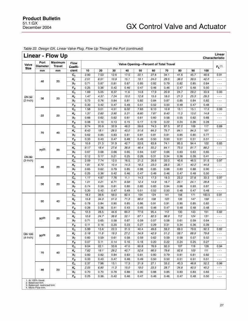
Table 22. Design GX, Linear Valve Plug, Flow Up Through the Port (continued)
Linear - Flow Up LinearCharacteristic
ValveSize
PortDiameter
MaximumTravel
FlowCoeffi-
Valve Opening—Percent of Total TravelFL
(1)Size
mm mmCoeffi-cient 10 20 30 40 50 60 70 80 90 100
FL( )
Cv 2.90 7.53 12.6 17.5 22.1 27.8 34.1 41.6 45.7 48.6 0.91
46 20Kv 2.51 6.51 10.9 15.1 19.1 24.0 29.5 36.0 39.5 42.0 - - -
46 20XT 0.71 0.87 0.81 0.87 0.85 0.82 0.79 0.82 0.85 0.84 - - -
Fd 0.25 0.36 0.42 0.46 0.47 0.46 0.46 0.47 0.48 0.50 - - -
Cv 1.69 5.05 8.37 11.6 14.8 17.9 20.9 24.7 29.2 33.9 0.93
DN 50 36 20Kv 1.47 4.37 7.24 10.0 12.8 15.5 18.0 21.3 25.3 29.3 - - -DN 50
(2-Inch)36 20
XT 0.73 0.76 0.84 0.81 0.82 0.84 0.87 0.85 0.84 0.82 - - -( )
Fd 0.30 0.42 0.47 0.49 0.51 0.52 0.50 0.48 0.47 0.48 - - -
Cv 1.58 3.01 4.51 6.02 7.63 9.10 10.9 13.1 15.1 17.2 0.93
22 20Kv 1.37 2.60 3.90 5.21 6.60 7.87 9.40 11.3 13.0 14.9 - - -
22 20XT 0.66 0.62 0.62 0.61 0.61 0.60 0.58 0.55 0.62 0.68 - - -
Fd 0.08 0.10 0.13 0.15 0.17 0.19 0.22 0.24 0.26 0.28 - - -
Cv 9.74 20.9 32.9 46.2 59.6 74.3 87.5 97.2 109 117 0.89
70 40Kv 8.43 18.1 28.5 40.0 51.6 64.3 75.7 84.1 94.3 101 - - -
70 40XT 0.62 0.85 0.83 0.81 0.81 0.81 0.81 0.85 0.80 0.77 - - -
Fd 0.33 0.43 0.47 0.48 0.49 0.50 0.50 0.51 0.51 0.51 - - -
Cv 10.6 21.3 31.9 42.7 53.6 63.8 74.1 85.0 94.4 102 0.85
70(2) 20Kv 9.17 18.4 27.6 36.9 46.4 55.2 64.1 73.5 81.7 88.2 - - -
70(2) 20XT 0.67 0.68 0.66 0.65 0.64 0.67 0.66 0.63 0.63 0.65 - - -
DN 80 Fd 0.12 0.17 0.21 0.25 0.28 0.31 0.34 0.36 0.39 0.41 - - -DN 80(3-Inch) Cv 2.09 7.74 12.0 16.5 21.2 26.6 33.0 40.6 46.5 51.8 0.97( )
46 20Kv 1.81 6.70 10.4 14.3 18.3 23.0 28.5 35.1 40.2 44.8 - - -
46 20XT 0.65 0.62 0.79 0.85 0.88 0.85 0.88 0.83 0.88 0.90 - - -
Fd 0.25 0.36 0.42 0.46 0.47 0.46 0.46 0.47 0.48 0.50 - - -
Cv 1.17 4.87 7.76 11.1 14.3 17.3 19.3 23.2 27.8 33.3 0.97
36 20Kv 1.01 4.21 6.71 9.58 12.4 14.9 16.7 20.1 24.1 28.8 - - -
36 20XT 0.74 0.59 0.81 0.80 0.82 0.83 0.94 0.96 0.93 0.87 - - -
Fd 0.30 0.42 0.47 0.49 0.51 0.52 0.50 0.48 0.47 0.48 - - -
Cv 18.2 39.6 59.0 82.4 104 124 141 156 171 183.5 0.91
90 40Kv 15.8 34.3 51.0 71.3 90.0 108 122 135 147 159 - - -
90 40XT 0.78 0.84 0.90 0.85 0.86 0.91 0.91 0.90 0.85 0.82 - - -
Fd 0.26 0.36 0.41 0.43 0.45 0.46 0.47 0.48 0.48 0.48 - - -
Cv 12.3 28.5 44.6 60.2 77.6 95.4 112 130 143 151 0.82
90(2) 20Kv 10.6 24.7 38.6 52.1 67.1 82.5 96.9 112 124 131 - - -
90(2) 20XT 0.71 0.65 0.58 0.67 0.59 0.57 0.58 0.61 0.59 0.64 - - -
Fd 0.11 0.16 0.20 0.23 0.27 0.29 0.31 0.34 0.36 0.39 - - -
Cv 5.99 13.6 22.3 31.5 40.4 49.6 59.2 69.0 79.6 92.3 0.82
DN 10090(3) 20
Kv 5.18 11.8 19.3 27.2 34.9 42.9 51.2 59.7 68.9 79.8 - - -DN 100(4-Inch)
90(3) 20XT 0.60 0.59 0.61 0.58 0.59 0.62 0.59 0.58 0.57 0.52 - - -( )
Fd 0.07 0.11 0.14 0.16 0.18 0.20 0.22 0.24 0.25 0.27 - - -
Cv 9.04 22.1 33.8 47.0 60.8 76.9 92.0 107 119 128 0.94
70 40Kv 7.82 19.1 29.2 40.7 52.6 66.5 79.6 92.6 103 111 - - -
70 40XT 0.80 0.82 0.84 0.83 0.81 0.80 0.79 0.81 0.81 0.82 - - -
Fd 0.33 0.43 0.47 0.48 0.49 0.50 0.50 0.51 0.51 0.51 - - -
Cv 2.37 7.98 13.1 17.3 21.9 27.1 33.2 40.3 46.8 52.2 0.96
46 20Kv 2.05 6.90 11.3 15.0 19.0 23.5 28.7 34.8 40.5 45.2 - - -
46 20XT 0.70 0.70 0.78 0.88 0.90 0.88 0.85 0.83 0.83 0.83 - - -
Fd 0.25 0.36 0.42 0.46 0.47 0.46 0.46 0.47 0.48 0.50 - - -1. At 100% travel.2. Balanced trim.3. Balanced, restricted trim.4. Micro-Flow trim.

GX Control Valve and ActuatorProduct Bulletin
51.1:GXDecember 2004
28
Note
Fisher does not assume responsibilityfor the selection, use, or maintenanceof any product. Responsibility forproper selection, use, andmaintenance of any Fisher productremains solely with the purchaser andend-user.
Fisher Marshalltown, Iowa 50158 USACernay 68700 France Sao Paulo 05424 BrazilSingapore 128461
The contents of this publication are presented for informational purposes only, and while every effort has been made to ensure their accuracy, they arenot to be construed as warranties or guarantees, express or implied, regarding the products or services described herein or their use or applicability.We reserve the right to modify or improve the designs or specifications of such products at any time without notice.
Fisher does not assume responsibility for the selection, use or maintenance of any product. Responsibility for proper selection, use and maintenance of any Fisher product remains solely with the purchaser and end-user.
�Fisher Controls International LLC 2003, 2004; All Rights Reserved Printed in USA
FIELDVUE, Micro-Flow, ValveLink, and Fisher are marks owned by Fisher Controls International LLC, a member of the Emerson ProcessManagement business division of Emerson Electric Co. The Emerson logo is a trademark and service mark of Emerson Electric Co. HART is amark owned by the HART Communications Foundation. FOUNDATION fieldbus is a mark owned by the Fieldbus Foundation. All other marks arethe property of their respective owners.
Emerson Process Management
www.Fisher.com