Embed Size (px)
Citation preview

J2X1-7671-08ENZ0(03)October 2020
Windows/Linux
FUJITSU SoftwareServerView Resource Orchestrator Virtual Edition V3.4.0
Design Guide

Preface
Purpose of This Document
This manual provides an outline of FUJITSU Software ServerView Resource Orchestrator Virtual Edition (hereinafter ResourceOrchestrator) and the design and preparations required for setup.
Intended Readers
This manual is written for people who will install Resource Orchestrator.When setting up systems, it is assumed that readers have the basic knowledge required to configure the servers, storage, and network devicesto be installed.
Structure of This Document
This manual is composed as follows:
Chapter 1 Documentation Road Map
Explains the documentation road map, and how to read it.
Chapter 2 Overview
Provides an overview of Resource Orchestrator.
Chapter 3 Flow of Resource Orchestrator Design and Preconfiguration
Explains the flow of design and pre-configuration for Resource Orchestrator.
Chapter 4 System Configuration Design
Explains points to keep in mind when setting up a Resource Orchestrator environment.
Chapter 5 Defining User Accounts
Explains the user accounts used in Resource Orchestrator.
Chapter 6 Defining and Configuring the Server Environment
Explains how to define and configure server environments.
Chapter 7 Defining and Configuring the Network Environment
Explains how to define and pre-configure the network environment.
Chapter 8 Deciding and Configuring the Storage Environment
Explains how to decide and configure the storage environment.
Chapter 9 Deciding and Configuring Server Virtualization Software
Explains how to decide and configure server virtualization software.
Chapter 10 Configuring Single Sign-On
Explains the function to perform Single Sign-On in coordination with ServerView Operations Manager.
Chapter 11 Deciding and Configuring the Power Monitoring Environment
Explains how to decide and configure the power monitoring environment.
Appendix A Port List
Explains the ports used by Resource Orchestrator.
Appendix B HTTPS Communications
Explains the HTTPS communication protocol used by Resource Orchestrator and its security features.
Appendix C Hardware Configuration
Explains how to configure hardware.
- i -

Appendix D Ethernet Fabric Devices
Explains the methods for managing Ethernet fabric devices.
Appendix E IPCOM VX Series Devices
Explains the methods for managing IPCOM VX series devices.
Web Site URLs
URLs provided as reference sources within the main text are correct as of October 2020.
Document Conventions
The notation in this manual conforms to the following conventions.
- When there is different information for the different versions of Resource Orchestrator, it is indicated as follows.
[All Editions] Sections relevant for all editions
[Cloud Edition] Sections related to Cloud Edition
[Virtual Edition] Sections related to Virtual Edition
- When using Resource Orchestrator and the functions necessary differ due to the necessary basic software (OS), it is indicated as follows:
[Windows Manager]
Sections related to Windows manager
[Linux Manager]
Sections related to Linux manager
[Windows]
Sections related to Windows
[Linux]
Sections related to Linux
[Red Hat Enterprise Linux]
Sections related to Red Hat Enterprise Linux
[Solaris]
Sections related to Solaris
[VMware]
Sections related to VMware
[Horizon View]
Sections related to VMware Horizon View
[Hyper-V]
Sections related to Hyper-V
[Xen]
Sections related to RHEL5-Xen
[KVM]
Sections related to RHEL-KVM
[Solaris Zones]
Sections related to Solaris Zones (Solaris 10) and Solaris Zones (Solaris 11)
- ii -

[Solaris Zones (Solaris 10)]
Sections related to Solaris Zones with Solaris 10 VM hosts
[Solaris Zones (Solaris 11)]
Sections related to Solaris Zones with Solaris 11 VM hosts
[OVM for x86]
Sections related to Oracle VM Server for x86 2.2 and Oracle VM Server for x86 3.x
[OVM for x86 2.2]
Sections related to Oracle VM Server for x86 2.2
[OVM for x86 3.x]
Sections related to Oracle VM Server for x86 3.2 and Oracle VM Server for x86 3.3
[OVM for SPARC]
Sections related to Oracle VM Server for SPARC
[Citrix Xen]
Sections related to Citrix XenServer
[Physical Servers]
Sections related to physical servers
[Trend Micro OfficeScan]
Sections related to Trend Micro OfficeScan
[Symantec]
Sections related to Symantec Endpoint Protection
[McAfee]
Sections related to McAfee ePolicy Orchestrator
- Unless specified otherwise, the blade servers mentioned in this manual refer to PRIMERGY BX servers.
- Oracle Solaris may also be indicated as Solaris, Solaris Operating System, or Solaris OS.
- Oracle Solaris Zones may also be indicated as Solaris Containers or Solaris Container.
- Oracle VM Server for x86 may also be indicated as Oracle VM.
- In Resource Orchestrator, the following servers are referred to as SPARC Enterprise.
- SPARC Enterprise M3000/M4000/M5000/M8000/M9000
- SPARC Enterprise T5120/T5140/T5220/T5240/T5440
- In Resource Orchestrator, the following servers are referred to as SPARC M12.
- SPARC M12-1/M12-2/M12-2S
- In Resource Orchestrator, the following servers are referred to as SPARC M10.
- SPARC M10-1/M10-4/M10-4S
- Fujitsu SPARC M12 is the product name used for SPARC M12 when they are sold outside Japan.
- Fujitsu M10 is the product name used for SPARC M10 when they are sold outside Japan.
- In this manual, Fujitsu SPARC M12 is referred to as SPARC M12.
- In this manual, Fujitsu M10 is referred to as SPARC M10.
- In this manual, Fujitsu SPARC M12 and Fujitsu M10 are collectively referred to as SPARC M10/M12.
- iii -

- In Resource Orchestrator, the following software is referred to as GLS.
- PRIMECLUSTER GLS 4.4 or earlier
- In Resource Orchestrator, the following software is referred to as GDS.
- PRIMECLUSTER GDS 4.4 or earlier
- References and character strings or values requiring emphasis are indicated using double quotes ( " ).
- GUI items are shown enclosed by brackets ([ ]).
- The order of selecting menus is indicated using [ ]-[ ].
- Text to be entered by the user is indicated using bold text.
- Variables are indicated using italic text and underscores.
- The ellipses ("...") in menu names, indicating settings and operation window startup, are not shown.
- The ">" used in Windows is included in usage examples. When using Linux, read ">" as meaning "#".
- When using Resource Orchestrator on Windows 8 and Windows Server 2012, please note the following.When OS operations are explained in this manual, the examples assume OSs up to Windows 7 and Windows Server 2008. When usingResource Orchestrator on Windows 8 or Windows Server 2012, take explanations regarding the [Start] menu as indicating the [Apps]screen.The [Apps] screen can be displayed by right-clicking on the [Start] screen and then right-clicking [All apps].
- When using Resource Orchestrator on Windows 8.1 and Windows Server 2012 R2, please note the following.When OS operations are explained in this manual, the examples assume OSs up to Windows 7 and Windows Server 2008. When usingResource Orchestrator on Windows 8.1 or Windows Server 2012 R2, take explanations regarding the [Start] menu as indicating the[Apps] screen.The [Apps] screen can be displayed by swiping the [Start] screen from bottom to top, or clicking the downward facing arrow on thelower-left of the [Start] screen.
Menus in the ROR console
Operations on the ROR console can be performed using either the menu bar or pop-up menus.
By convention, procedures described in this manual only refer to pop-up menus.
Regarding Installation Folder Paths
The installation folder path may be given as C:\Fujitsu\ROR in this manual.
Replace it as shown below.
[Virtual Edition]
- When using Windows 64-bit (x64)
C:\Program Files (x86)\Resource Orchestrator
- When using Windows 32-bit (x86)
C:\Program Files\Resource Orchestrator
[Cloud Edition]
C:\Program Files (x86)\Resource Orchestrator
Command Examples
The paths used in command examples may be abbreviated. When using commands, execute them using the paths in the "Name" column inthe "Reference Guide (Command) VE" and the "Reference Guide (Command/XML) CE".
- iv -

Abbreviations
The following abbreviations are use in this manual.
Category
Abbreviation
- Products
Windows
Windows
- Microsoft(R) Windows Server(R) 2012 Standard
- Microsoft(R) Windows Server(R) 2012 Datacenter
- Microsoft(R) Windows Server(R) 2012 R2 Essentials
- Microsoft(R) Windows Server(R) 2012 R2 Standard
- Microsoft(R) Windows Server(R) 2012 R2 Datacenter
- Microsoft(R) Windows Server(R) 2016 Standard
- Microsoft(R) Windows Server(R) 2016 Datacenter
- Microsoft(R) Windows Server(R) 2019 Standard
- Microsoft(R) Windows Server(R) 2019 Datacenter
- Windows(R) 7 Professional
- Windows(R) 7 Ultimate
- Windows(R) 8.1 Pro
- Windows(R) 8.1 Enterprise
- Windows(R) 10 Pro
- Windows(R) 10 Enterprise
Windows Server 2012
- Microsoft(R) Windows Server(R) 2012 Standard
- Microsoft(R) Windows Server(R) 2012 Datacenter
- Microsoft(R) Windows Server(R) 2012 R2 Essentials
- Microsoft(R) Windows Server(R) 2012 R2 Standard
- Microsoft(R) Windows Server(R) 2012 R2 Datacenter
Windows Server 2016
- Microsoft(R) Windows Server(R) 2016 Standard
- Microsoft(R) Windows Server(R) 2016 Datacenter
Windows Server 2019
- Microsoft(R) Windows Server(R) 2019 Standard
- Microsoft(R) Windows Server(R) 2019 Datacenter
Windows PE
- Microsoft(R) Windows(R) Preinstallation Environment
Windows 7
- v -

- Windows(R) 7 Professional
- Windows(R) 7 Ultimate
Windows 8.1
- Windows(R) 8.1 Pro
- Windows(R) 8.1 Enterprise
Windows 10
- Windows(R) 10 Pro
- Windows(R) 10 Enterprise
DOS
- Microsoft(R) MS-DOS(R) operating system, DR DOS(R)
MSFC
- Microsoft(R) Windows Server(R) 2012 Standard Failover Cluster
- Microsoft(R) Windows Server(R) 2012 Datacenter Failover Cluster
SCVMM
- Microsoft(R) System Center 2012 Virtual Machine Manager
- Microsoft(R) System Center 2012 R2 Virtual Machine Manager
- Microsoft(R) System Center 2016 Virtual Machine Manager
Linux
Linux
- Red Hat(R) Enterprise Linux(R) 6.0 (for x86)
- Red Hat(R) Enterprise Linux(R) 6.0 (for Intel64)
- Red Hat(R) Enterprise Linux(R) 6.1 (for x86)
- Red Hat(R) Enterprise Linux(R) 6.1 (for Intel64)
- Red Hat(R) Enterprise Linux(R) 6.2 (for x86)
- Red Hat(R) Enterprise Linux(R) 6.2 (for Intel64)
- Red Hat(R) Enterprise Linux(R) 6.3 (for x86)
- Red Hat(R) Enterprise Linux(R) 6.3 (for Intel64)
- Red Hat(R) Enterprise Linux(R) 6.4 (for x86)
- Red Hat(R) Enterprise Linux(R) 6.4 (for Intel64)
- Red Hat(R) Enterprise Linux(R) 6.5 (for x86)
- Red Hat(R) Enterprise Linux(R) 6.5 (for Intel64)
- Red Hat(R) Enterprise Linux(R) 6.6 (for x86)
- Red Hat(R) Enterprise Linux(R) 6.6 (for Intel64)
- Red Hat(R) Enterprise Linux(R) 6.7 (for x86)
- Red Hat(R) Enterprise Linux(R) 6.7 (for Intel64)
- Red Hat(R) Enterprise Linux(R) 6.8 (for x86)
- Red Hat(R) Enterprise Linux(R) 6.8 (for Intel64)
- vi -

- Red Hat(R) Enterprise Linux(R) 6.9 (for x86)
- Red Hat(R) Enterprise Linux(R) 6.9 (for Intel64)
- Red Hat(R) Enterprise Linux(R) 6.10 (for x86)
- Red Hat(R) Enterprise Linux(R) 6.10 (for Intel64)
- Red Hat(R) Enterprise Linux(R) 7.0 (for Intel64)
- Red Hat(R) Enterprise Linux(R) 7.1 (for Intel64)
- Red Hat(R) Enterprise Linux(R) 7.2 (for Intel64)
- Red Hat(R) Enterprise Linux(R) 7.4 (for Intel64)
- Red Hat(R) Enterprise Linux(R) 7.5 (for Intel64)
- SUSE(R) Linux Enterprise Server 10 Service Pack 2 for x86
- SUSE(R) Linux Enterprise Server 10 Service Pack 2 for AMD64 & Intel64
- SUSE(R) Linux Enterprise Server 10 Service Pack 3 for x86
- SUSE(R) Linux Enterprise Server 10 Service Pack 3 for AMD64 & Intel64
- SUSE(R) Linux Enterprise Server 11 for x86
- SUSE(R) Linux Enterprise Server 11 for AMD64 & Intel64
- SUSE(R) Linux Enterprise Server 11 Service Pack 1 for x86
- SUSE(R) Linux Enterprise Server 11 Service Pack 1 for AMD64 & Intel64
- Oracle Enterprise Linux Release 6.7 for x86 (32-bit)
- Oracle Enterprise Linux Release 6.7 for x86_64 (64-bit)
- Oracle Enterprise Linux Release 7.2 for x86 (32-bit)
- Oracle Enterprise Linux Release 7.2 for x86_64 (64-bit)
Red Hat Enterprise Linux
- Red Hat(R) Enterprise Linux(R) 6.0 (for x86)
- Red Hat(R) Enterprise Linux(R) 6.0 (for Intel64)
- Red Hat(R) Enterprise Linux(R) 6.1 (for x86)
- Red Hat(R) Enterprise Linux(R) 6.1 (for Intel64)
- Red Hat(R) Enterprise Linux(R) 6.2 (for x86)
- Red Hat(R) Enterprise Linux(R) 6.2 (for Intel64)
- Red Hat(R) Enterprise Linux(R) 6.3 (for x86)
- Red Hat(R) Enterprise Linux(R) 6.3 (for Intel64)
- Red Hat(R) Enterprise Linux(R) 6.4 (for x86)
- Red Hat(R) Enterprise Linux(R) 6.4 (for Intel64)
- Red Hat(R) Enterprise Linux(R) 6.5 (for x86)
- Red Hat(R) Enterprise Linux(R) 6.5 (for Intel64)
- Red Hat(R) Enterprise Linux(R) 6.6 (for x86)
- Red Hat(R) Enterprise Linux(R) 6.6 (for Intel64)
- Red Hat(R) Enterprise Linux(R) 6.7 (for x86)
- Red Hat(R) Enterprise Linux(R) 6.7 (for Intel64)
- vii -

- Red Hat(R) Enterprise Linux(R) 6.8 (for x86)
- Red Hat(R) Enterprise Linux(R) 6.8 (for Intel64)
- Red Hat(R) Enterprise Linux(R) 6.9 (for x86)
- Red Hat(R) Enterprise Linux(R) 6.9 (for Intel64)
- Red Hat(R) Enterprise Linux(R) 6.10 (for x86)
- Red Hat(R) Enterprise Linux(R) 6.10 (for Intel64)
- Red Hat(R) Enterprise Linux(R) 7.0 (for Intel64)
- Red Hat(R) Enterprise Linux(R) 7.1 (for Intel64)
- Red Hat(R) Enterprise Linux(R) 7.2 (for Intel64)
- Red Hat(R) Enterprise Linux(R) 7.4 (for Intel64)
- Red Hat(R) Enterprise Linux(R) 7.5 (for Intel64)
Red Hat Enterprise Linux 6
- Red Hat(R) Enterprise Linux(R) 6.0 (for x86)
- Red Hat(R) Enterprise Linux(R) 6.0 (for Intel64)
- Red Hat(R) Enterprise Linux(R) 6.1 (for x86)
- Red Hat(R) Enterprise Linux(R) 6.1 (for Intel64)
- Red Hat(R) Enterprise Linux(R) 6.2 (for x86)
- Red Hat(R) Enterprise Linux(R) 6.2 (for Intel64)
- Red Hat(R) Enterprise Linux(R) 6.3 (for x86)
- Red Hat(R) Enterprise Linux(R) 6.3 (for Intel64)
- Red Hat(R) Enterprise Linux(R) 6.4 (for x86)
- Red Hat(R) Enterprise Linux(R) 6.4 (for Intel64)
- Red Hat(R) Enterprise Linux(R) 6.5 (for x86)
- Red Hat(R) Enterprise Linux(R) 6.5 (for Intel64)
- Red Hat(R) Enterprise Linux(R) 6.6 (for x86)
- Red Hat(R) Enterprise Linux(R) 6.6 (for Intel64)
- Red Hat(R) Enterprise Linux(R) 6.7 (for x86)
- Red Hat(R) Enterprise Linux(R) 6.7 (for Intel64)
- Red Hat(R) Enterprise Linux(R) 6.8 (for x86)
- Red Hat(R) Enterprise Linux(R) 6.8 (for Intel64)
- Red Hat(R) Enterprise Linux(R) 6.9 (for x86)
- Red Hat(R) Enterprise Linux(R) 6.9 (for Intel64)
- Red Hat(R) Enterprise Linux(R) 6.10 (for x86)
- Red Hat(R) Enterprise Linux(R) 6.10 (for Intel64)
Red Hat Enterprise Linux 7
- Red Hat(R) Enterprise Linux(R) 7.0 (for Intel64)
- Red Hat(R) Enterprise Linux(R) 7.1 (for Intel64)
- Red Hat(R) Enterprise Linux(R) 7.2 (for Intel64)
- viii -

- Red Hat(R) Enterprise Linux(R) 7.4 (for Intel64)
- Red Hat(R) Enterprise Linux(R) 7.5 (for Intel64)
SUSE Linux Enterprise Server
- SUSE(R) Linux Enterprise Server 10 Service Pack 2 for x86
- SUSE(R) Linux Enterprise Server 10 Service Pack 2 for AMD64 & Intel64
- SUSE(R) Linux Enterprise Server 10 Service Pack 3 for x86
- SUSE(R) Linux Enterprise Server 10 Service Pack 3 for AMD64 & Intel64
- SUSE(R) Linux Enterprise Server 11 for x86
- SUSE(R) Linux Enterprise Server 11 for AMD64 & Intel64
- SUSE(R) Linux Enterprise Server 11 Service Pack 1 for x86
- SUSE(R) Linux Enterprise Server 11 Service Pack 1 for AMD64 & Intel64
Oracle Enterprise Linux
- Oracle Enterprise Linux Release 6.7 for x86 (32-bit)
- Oracle Enterprise Linux Release 6.7 for x86_64 (64-bit)
- Oracle Enterprise Linux Release 7.2 for x86 (32-bit)
- Oracle Enterprise Linux Release 7.2 for x86_64 (64-bit)
KVM
RHEL-KVM
- Red Hat(R) Enterprise Linux(R) 6.1 (for x86) Virtual Machine Function
- Red Hat(R) Enterprise Linux(R) 6.1 (for Intel64) Virtual Machine Function
- Red Hat(R) Enterprise Linux(R) 6.2 (for x86) Virtual Machine Function
- Red Hat(R) Enterprise Linux(R) 6.2 (for Intel64) Virtual Machine Function
- Red Hat(R) Enterprise Linux(R) 6.3 (for x86) Virtual Machine Function
- Red Hat(R) Enterprise Linux(R) 6.3 (for Intel64) Virtual Machine Function
- Red Hat(R) Enterprise Linux(R) 6.4 (for x86) Virtual Machine Function
- Red Hat(R) Enterprise Linux(R) 6.4 (for Intel64) Virtual Machine Function
- Red Hat(R) Enterprise Linux(R) 6.5 (for x86) Virtual Machine Function
- Red Hat(R) Enterprise Linux(R) 6.5 (for Intel64) Virtual Machine Function
- Red Hat(R) Enterprise Linux(R) 6.6 (for x86) Virtual Machine Function
- Red Hat(R) Enterprise Linux(R) 6.6 (for Intel64) Virtual Machine Function
- Red Hat(R) Enterprise Linux(R) 6.7 (for x86) Virtual Machine Function
- Red Hat(R) Enterprise Linux(R) 6.7 (for Intel64) Virtual Machine Function
- Red Hat(R) Enterprise Linux(R) 6.8 (for x86) Virtual Machine Function
- Red Hat(R) Enterprise Linux(R) 6.8 (for Intel64) Virtual Machine Function
Xen
Xen
- ix -

- Citrix XenServer(R) 5.5
- Citrix Essentials(TM) for XenServer 5.5, Enterprise Edition
- Citrix XenServer(R) 6.0
- Citrix Essentials(TM) for XenServer 6.0, Enterprise Edition
Citrix
Citrix XenServer
- Citrix XenServer(R) 6.0
- Citrix XenServer(R) 6.0.2
- Citrix XenServer(R) 6.1.0
- Citrix XenServer(R) 6.2.0
- Citrix XenServer(R) 7.1 LTSR
- Citrix XenServer(R) 7.2
- Citrix Hypervisor(R)
XenServer 6
- Citrix XenServer(R) 6.0
- Citrix Essentials(TM) for XenServer 6.0, Enterprise Edition
Citrix XenApp
- Citrix XenApp(R)
- Citrix Virtual Apps(R)
Citrix XenDesktop
- Citrix XenDesktop(R)
- Citrix Virtual Apps and Desktops(R)
Oracle Solaris
Solaris
- Oracle Solaris 10 05/09 (Update7)
- Oracle Solaris 11 11/11
- Oracle Solaris 11.1
- Oracle Solaris 11.2
- Oracle Solaris 11.3
Oracle VM
OVM for x86 2.2
- Oracle(R) VM Server for x86 2.2
OVM for x86 3.x
OVM for x86 3.2
- Oracle VM Server for x86 v3.2.x
OVM for x86 3.3
- Oracle VM Server for x86 v3.3.x
- x -

OVM for SPARC
- Oracle(R) VM Server for SPARC
Oracle VM Manager
- Oracle(R) VM Manager
EMC
Navisphere
- EMC Navisphere Manager
Solutions Enabler
- EMC Solutions Enabler
VMware
VMware vSphere or vSphere
- VMware vSphere(R) 4
- VMware vSphere(R) 4.1
- VMware vSphere(R) 5
- VMware vSphere(R) 5.1
- VMware vSphere(R) 5.5
- VMware vSphere(R) 6
- VMware vSphere(R) 6.5
- VMware vSphere(R) 6.7
VMware ESX
- VMware(R) ESX(R)
VMware ESX 4
- VMware(R) ESX(R) 4
VMware ESXi
- VMware(R) ESXi(TM)
VMware ESXi 5.0
- VMware(R) ESXi(TM) 5.0
VMware ESXi 5.1
- VMware(R) ESXi(TM) 5.1
VMware ESXi 5.5
- VMware(R) ESXi(TM) 5.5
VMware ESXi 6.0
- VMware(R) ESXi(TM) 6.0
VMware ESXi 6.5
- VMware(R) ESXi(TM) 6.5
VMware ESXi 6.7
- VMware(R) ESXi(TM) 6.7
- xi -

VMware Infrastructure Client
- VMware(R) Infrastructure Client
VMware Tools
- VMware(R) Tools
VMware vSphere 4.0 or vSphere 4.0
- VMware vSphere(R) 4.0
VMware vSphere 4.1 or vSphere 4.1
- VMware vSphere(R) 4.1
VMware vSphere 5 or vSphere 5
- VMware vSphere(R) 5
VMware vSphere 5.1 or vSphere 5.1
- VMware vSphere(R) 5.1
VMware vSphere 5.5 or vSphere 5.5
- VMware vSphere(R) 5.5
VMware vSphere 6.0 or vSphere 6.0
- VMware vSphere(R) 6.0
VMware vSphere 6.5 or vSphere 6.5
- VMware vSphere(R) 6.5
VMware vSphere 6.7 or vSphere 6.7
- VMware vSphere(R) 6.7
VMware vSphere Client or vSphere Client
- VMware vSphere(R) Client
VMware vCenter Server or vCenter Server
- VMware(R) vCenter(TM) Server
VMware vCenter Server Appliance or vCenter Server Appliance
- VMware(R) vCenter(TM) Server Appliance(TM)
VMware vClient
- VMware(R) vClient(TM)
VMware FT
- VMware(R) Fault Tolerance
VMware DRS
- VMware(R) Distributed Resource Scheduler
VMware DPM
- VMware(R) Distributed Power Management
VMware Storage VMotion
- VMware(R) Storage VMotion
VMware vDS
- VMware(R) vNetwork Distributed Switch
- xii -

VMware Horizon View
- VMware Horizon View 5.2.x
- VMware Horizon View 5.3.x
- VMware Horizon 6.0 (with View)
VMware VSAN or VSAN
- VMware(R) Virtual SAN(TM)
VMware vSphere Web Client or vSphere Web Client
- VMware vSphere(R) Web Client
VMware NSX
- VMware NSX(R)
- VMware NSX(R) for vSphere(R)
- VMware NSX(R) for vSphere(R) 6.3
VMware NSX Controller or NSX Controller
- VMware NSX(R) Controller(TM)
VMware NSX Edge or NSX Edge
- VMware NSX(R) Edge(TM)
VMware NSX Manager or NSX Manager
- VMware NSX(R) Manager(TM)
Excel
Excel
- Microsoft(R) Office Excel(R) 2007
- Microsoft(R) Office Excel(R) 2010
- Microsoft(R) Office Excel(R) 2013
Excel 2007
- Microsoft(R) Office Excel(R) 2007
Excel 2010
- Microsoft(R) Office Excel(R) 2010
Excel 2013
- Microsoft(R) Office Excel(R) 2013
Browsers
Internet Explorer
- Windows(R) Internet Explorer(R) 9
- Internet Explorer(R) 10
- Internet Explorer(R) 11
Firefox
- Firefox(R)
- xiii -

Antivirus Software
OfficeScan
- Trend Micro OfficeScan
McAfee ePolicy Orchestrator
- McAfee(R) ePolicy Orchestrator(R)
McAfee ePO
- McAfee(R) ePolicy Orchestrator(R)
McAfee Agent
- McAfee(R) Agent
McAfee Endpoint Security
- McAfee(R) Endpoint Security
Symantec Endpoint Protection
- Symantec(TM) Endpoint Protection
Symantec Endpoint Protection Manager
- Symantec(TM) Endpoint Protection Manager
BMC
BladeLogic
- BMC BladeLogic Server Automation
ETERNUS
ESC
- ETERNUS SF Storage Cruiser
ServerView
ServerView Agent
- ServerView SNMP Agents for MS Windows (32-bit and 64-bit)
- ServerView Agents Linux
- ServerView Agents VMware for VMware ESX Server
VIOM
- ServerView Virtual-IO Manager
ISM
- ServerView Infrastructure Manager
- Infrastructure Manager
SVOM
- ServerView Operations Manager
SVFAB
- ServerView Fabric Manager
- xiv -

RCVE
- ServerView Resource Coordinator VE
ROR
- FUJITSU Software ServerView Resource Orchestrator
ROR VE
- FUJITSU Software ServerView Resource Orchestrator Virtual Edition
ROR CE
- FUJITSU Software ServerView Resource Orchestrator Cloud Edition
Resource Coordinator
- Systemwalker Resource Coordinator
- Systemwalker Resource Coordinator Virtual server Edition
Resource Coordinator VE
- ServerView Resource Coordinator VE
- Systemwalker Resource Coordinator Virtual server Edition
Resource Orchestrator
- FUJITSU Software ServerView Resource Orchestrator
Export Administration Regulation Declaration
Exportation/release of this document may require necessary procedures in accordance with the regulations of your resident country and/orUS export control laws.
Trademark Information
- BMC, BMC Software, and the BMC Software logo are the exclusive properties of BMC Software, Inc., are registered with the U.S.Patent and Trademark Office, and may be registered or pending registration in other countries.
- Citrix, Citrix Virtual Apps and Desktops, Citrix Virtual Apps, Citrix Hypervisor, XenApp, XenDesktop, XenServer, Citrix Essentialsare trademarks of Citrix Systems, Inc. and/or one of its subsidiaries, and may be registered in the United States Patent and TrademarkOffice and in other countries.
- Dell is a registered trademark of Dell Computer Corp.
- HP is a registered trademark of Hewlett-Packard Company.
- IBM is a registered trademark or trademark of International Business Machines Corporation in the U.S.
- Linux(R) is a trademark or registered trademark of Linus Torvalds in the United States and other countries.
- McAfee and the McAfee logo, ePolicy Orchestrator, and McAfee ePO are trademarks or registered trademarks of McAfee, LLC or itssubsidiaries in the United States and other countries.
- Microsoft, Windows, MS-DOS, Windows Server, Windows Vista, Excel, Active Directory, and Internet Explorer are either registeredtrademarks or trademarks of Microsoft Corporation in the United States and other countries.
- Firefox is a trademark or registered trademark of the Mozilla Foundation in the United States and other countries.
- Oracle and Java are registered trademarks of Oracle and/or its affiliates.
- Red Hat, RPM and all Red Hat-based trademarks and logos are trademarks or registered trademarks of Red Hat, Inc. in the United Statesand other countries.
- Spectrum is a trademark or registered trademark of Computer Associates International, Inc. and/or its subsidiaries.
- xv -
- SUSE and the SUSE logo are trademarks of SUSE IP Development Limited or its subsidiaries or affiliates.
- Symantec and the Symantec logo are trademarks or registered trademarks of the Symantec Corporation or its subsidiaries in the UnitedStates and other countries.
- TREND MICRO and OfficeScan are registered trademarks of Trend Micro, Inc.
- VMware, the VMware "boxes" logo and design, Virtual SMP, and VMotion are registered trademarks or trademarks of VMware, Inc.in the United States and/or other jurisdictions.
- ServerView and Systemwalker are registered trademarks of FUJITSU LIMITED.
- All other brand and product names are trademarks or registered trademarks of their respective owners.
Notices
- The contents of this manual shall not be reproduced without express written permission from FUJITSU LIMITED.
- The contents of this manual are subject to change without notice.
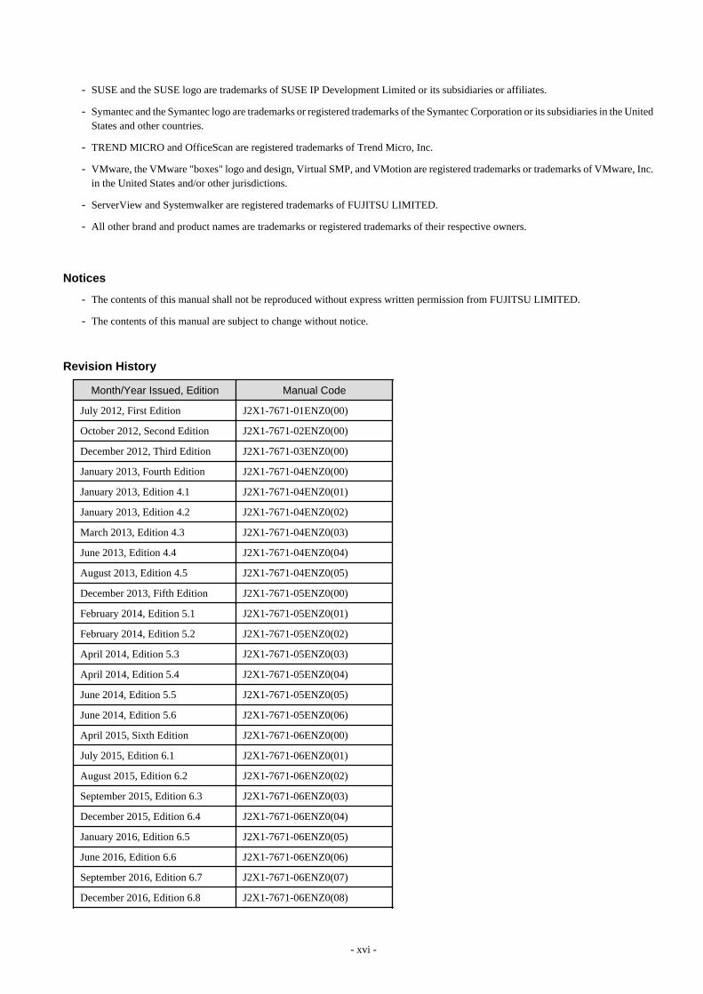
Revision History
Month/Year Issued, Edition Manual Code
July 2012, First Edition J2X1-7671-01ENZ0(00)
October 2012, Second Edition J2X1-7671-02ENZ0(00)
December 2012, Third Edition J2X1-7671-03ENZ0(00)
January 2013, Fourth Edition J2X1-7671-04ENZ0(00)
January 2013, Edition 4.1 J2X1-7671-04ENZ0(01)
January 2013, Edition 4.2 J2X1-7671-04ENZ0(02)
March 2013, Edition 4.3 J2X1-7671-04ENZ0(03)
June 2013, Edition 4.4 J2X1-7671-04ENZ0(04)
August 2013, Edition 4.5 J2X1-7671-04ENZ0(05)
December 2013, Fifth Edition J2X1-7671-05ENZ0(00)
February 2014, Edition 5.1 J2X1-7671-05ENZ0(01)
February 2014, Edition 5.2 J2X1-7671-05ENZ0(02)
April 2014, Edition 5.3 J2X1-7671-05ENZ0(03)
April 2014, Edition 5.4 J2X1-7671-05ENZ0(04)
June 2014, Edition 5.5 J2X1-7671-05ENZ0(05)
June 2014, Edition 5.6 J2X1-7671-05ENZ0(06)
April 2015, Sixth Edition J2X1-7671-06ENZ0(00)
July 2015, Edition 6.1 J2X1-7671-06ENZ0(01)
August 2015, Edition 6.2 J2X1-7671-06ENZ0(02)
September 2015, Edition 6.3 J2X1-7671-06ENZ0(03)
December 2015, Edition 6.4 J2X1-7671-06ENZ0(04)
January 2016, Edition 6.5 J2X1-7671-06ENZ0(05)
June 2016, Edition 6.6 J2X1-7671-06ENZ0(06)
September 2016, Edition 6.7 J2X1-7671-06ENZ0(07)
December 2016, Edition 6.8 J2X1-7671-06ENZ0(08)
- xvi -

Month/Year Issued, Edition Manual Code
February 2017, Edition 6.9 J2X1-7671-06ENZ0(09)
February 2017, Edition 6.10 J2X1-7671-06ENZ0(10)
February 2017, Edition 6.11 J2X1-7671-06ENZ0(11)
April 2017, Seventh Edition J2X1-7671-07ENZ0(00)
May 2017, Edition 7.1 J2X1-7671-07ENZ0(01)
August 2017, Edition 7.2 J2X1-7671-07ENZ0(02)
September 2017, Edition 7.3 J2X1-7671-07ENZ0(03)
December 2017, Edition 7.4 J2X1-7671-07ENZ0(04)
February 2018, Edition 7.5 J2X1-7671-07ENZ0(05)
March 2018, Edition 7.6 J2X1-7671-07ENZ0(06)
October 2018, Eighth Edition J2X1-7671-08ENZ0(00)
December 2018, Edition 8.1 J2X1-7671-08ENZ0(01)
December 2018, Edition 8.2 J2X1-7671-08ENZ0(02)
October 2020, Edition 8.3 J2X1-7671-08ENZ0(03)
Copyright
Copyright 2012-2020 FUJITSU LIMITED
- xvii -

ContentsChapter 1 Documentation Road Map.......................................................................................................................................1
Chapter 2 Overview..................................................................................................................................................................22.1 Features................................................................................................................................................................................................22.2 Function Overview.............................................................................................................................................................................. 52.3 Functional Differences Depending on Product..................................................................................................................................102.4 Software Environment....................................................................................................................................................................... 102.5 Hardware Environment......................................................................................................................................................................102.6 System Configuration........................................................................................................................................................................ 10
Chapter 3 Flow of Resource Orchestrator Design and Preconfiguration............................................................................... 11
Chapter 4 System Configuration Design................................................................................................................................ 13
Chapter 5 Defining User Accounts......................................................................................................................................... 17
Chapter 6 Defining and Configuring the Server Environment................................................................................................ 196.1 Defining the Server Environment...................................................................................................................................................... 19
6.1.1 Settings for Blade Servers...........................................................................................................................................................196.1.2 Settings for Rack Mount and Tower Servers..............................................................................................................................206.1.3 Settings for PRIMEQUEST........................................................................................................................................................216.1.4 Setting Values for SPARC Enterprise (M3000/T5120/T5140/T5220/T5240/T5440) and SPARC M10-1/M10-4/M12-1/M12-2
............................................................................................................................................................................................ 226.1.5 Setting Values for SPARC Enterprise M4000/M5000/M8000/M9000 and SPARC M10-4S/M12-2S.....................................236.1.6 Settings when Switching Over SPARC M10/M12 or SPARC Enterprise Servers.................................................................... 25
6.2 Configuring the Server Environment.................................................................................................................................................266.2.1 Configuring Blade Servers..........................................................................................................................................................276.2.2 Configuring Rack Mount and Tower Servers.............................................................................................................................276.2.3 Configuring PRIMEQUEST.......................................................................................................................................................286.2.4 Configuring SPARC Enterprise M3000 and SPARC M10-1/M10-4/M12-1/M12-2.................................................................286.2.5 Configuring SPARC Enterprise M4000/M5000/M8000/M9000 and SPARC M10-4S/M12-2S.............................................. 296.2.6 Configuring SPARC Enterprise T5120/T5140/T5220/T5240/T5440........................................................................................ 296.2.7 Configuring BIOS Settings of Managed Servers........................................................................................................................306.2.8 Configuring OS Settings of Managed Servers............................................................................................................................336.2.9 Configuring OBP (Open Boot Prom) Settings (SPARC M10/M12 and SPARC Enterprise).................................................... 346.2.10 Configuring ServerView Operations Manager (VMware ESXi)............................................................................................. 34
Chapter 7 Defining and Configuring the Network Environment..............................................................................................357.1 Network Configuration...................................................................................................................................................................... 357.2 IP Addresses (Admin LAN).............................................................................................................................................................. 497.3 IP Addresses (iSCSI LAN)................................................................................................................................................................ 507.4 Public LAN Settings for Managed Servers........................................................................................................................................507.5 Network Device Management Settings............................................................................................................................................. 507.6 Configuring the Network Environment............................................................................................................................................. 527.7 When Managing Network Devices as Resources.............................................................................................................................. 54
7.7.1 Settings for Managed Network Devices..................................................................................................................................... 547.7.1.1 Settings for Management..................................................................................................................................................... 547.7.1.2 Settings for Pre-configuration..............................................................................................................................................55
7.7.2 Pre-configuring Managed Network Devices.............................................................................................................................. 577.7.3 Creating Network Configuration Information (XML Definition).............................................................................................. 58
Chapter 8 Deciding and Configuring the Storage Environment..............................................................................................648.1 Deciding the Storage Environment....................................................................................................................................................64
8.1.1 Storage Configuration.................................................................................................................................................................648.1.2 HBA and Storage Device Settings..............................................................................................................................................658.1.3 iSCSI Interface and Storage Device Settings (iSCSI)................................................................................................................ 68
8.2 Configuring the Storage Environment...............................................................................................................................................69
- xviii -

Chapter 9 Deciding and Configuring Server Virtualization Software......................................................................................719.1 Deciding Server Virtualization Software...........................................................................................................................................719.2 Configuring Server Virtualization Software......................................................................................................................................74
9.2.1 Configuration Requirements.......................................................................................................................................................749.2.2 Functional Differences between Products.................................................................................................................................. 829.2.3 Definition Files of Each Product................................................................................................................................................ 87
Chapter 10 Configuring Single Sign-On................................................................................................................................. 9110.1 Deciding the Directory Service to Use............................................................................................................................................ 9210.2 Setting Up ServerView Operations Manager and the Directory Service Environment.................................................................. 92
10.2.1 To Use a User already Registered with Active Directory as a Resource Orchestrator User....................................................9210.2.2 Single Sign-On When Using the ServerView Operations Manager Console...........................................................................9310.2.3 When Installing ServerView Operations Manager Again........................................................................................................ 95
10.3 Registering Administrators.............................................................................................................................................................. 95
Chapter 11 Deciding and Configuring the Power Monitoring Environment............................................................................ 9711.1 Deciding the Power Monitoring Environment.................................................................................................................................97
11.1.1 Settings for the Power Monitoring Environment......................................................................................................................9711.1.2 Power Monitoring Device Settings...........................................................................................................................................97
11.2 Configuring the Power Monitoring Environment............................................................................................................................98
Appendix A Port List...............................................................................................................................................................99
Appendix B HTTPS Communications...................................................................................................................................110
Appendix C Hardware Configuration....................................................................................................................................115C.1 Connections between Server Network Interfaces and LAN Switch Ports......................................................................................115C.2 WWN Allocation Order during HBA address rename Configuration............................................................................................ 116
Appendix D Ethernet Fabric Devices....................................................................................................................................118D.1 Fujitsu PRIMERGY Converged Fabric Switch Blade (10 Gbps 18/8+2) and Fujitsu Converged Fabric Switch......................... 118
D.1.1 Management Unit.....................................................................................................................................................................118D.2 Extreme VCS Fabric....................................................................................................................................................................... 119
D.2.1 Management Unit.....................................................................................................................................................................119
Appendix E IPCOM VX Series Devices................................................................................................................................120E.1 IPCOM VX Series...........................................................................................................................................................................120
E.1.1 Management Unit..................................................................................................................................................................... 120
- xix -

Chapter 1 Documentation Road MapFor the documentation road map, refer to "Documentation Road Map".
- 1 -

Chapter 2 OverviewThis chapter provides an overview of Resource Orchestrator.
2.1 FeaturesResource Orchestrator is server management software that improves the usability and availability of server systems. It uniformly managesphysical servers as well as virtual servers created using server virtualization software (VMware and others).
The level of functionality provided by Resource Orchestrator differs depending on the managed hardware environment.For details, refer to "Functions Available for Agents" in "6.2.1 All Editions" in the "Overview".
This section explains some of the features provided by Resource Orchestrator.
- Integrated management of physical and virtual servers
Resource Orchestrator provides an integrated management console for environments composed of physical and virtual servers. It helpsadministrators manage server configurations, monitor hardware failures, and determine the cause and impact of system errors byautomatically detecting and displaying the following information.
- Resource Orchestrator provides a tree-based view of chassis and server hardware and their operating systems (physical OS, VMhost, or VM guest).This enables easy confirmation and tracking of relationships between chassis, servers, and operating systems.
- Resource Orchestrator monitors server hardware and displays icons representative of each server's status.
Resource Orchestrator also allows administrators to manage both physical and virtual servers in a uniform manner. Once registered,resources can be managed uniformly regardless of server models, types of server virtualization software, or differences betweenphysical and virtual servers.
- Auto-Recovery of failed servers
The function allows failed applications to automatically be recovered onto an available spare server by pre-allocating spare servers tomanaged servers.Depending on the server's boot method, one of the four following switchover methods can be used to recover applications on a spareserver:
- Backup and restore
This method is used in local boot environments where servers boot from an internal disk. Backing up the system disk of a primaryserver in advance allows automatic restoration and startup of the spare server when the primary server fails.
- HBA address rename
This method is used in SAN boot environments where servers start from boot disks located in SAN storage arrays. If the primaryserver fails, its World Wide Name (WWN) is inherited by the spare server, which then automatically starts up from the same SANdisk. This is made possible by the I/O virtualization (*) capabilities of the HBA address rename function, which is able todynamically reconfigure the WWN of an I/O adapter (HBA).
- Profile exchange
This method is used in environments where servers start from boot disks located in SAN storage arrays or on a storage deviceconnected to the LAN. If the primary server fails, the World Wide Name (WWN), MAC address, boot configuration, and networkconfiguration set in its profile in advance using I/O virtualization using VIOM or ISM are inherited by the spare server, which thenautomatically starts up from the same boot disk.For details on profiles, refer to the manuals of ServerView Virtual-IO Manager or ServerView Infrastructure Manager.
* Note: Refer to "I/O Virtualization".
- Storage affinity switchover method
This method is used in SAN boot environments where servers start from boot disks located in SAN storage arrays. If the primaryserver fails, its switch zoning and host affinity configurations set in the fibre channel switch and the SAN storage using ESC areinherited by the WWN (World Wide Name) of the spare server, which then automatically starts up from the same SAN disk.
- 2 -

The following LAN switch settings can also be exchanged between primary and spare servers during server switchover. This featuresupports the backup and restore, HBA address rename, and profile switchover methods.
- VLAN
- Port groups (For PRIMERGY BX900/BX400 LAN switch blades operating in IBP mode)
Several servers can share one or more common spare servers, irrespective of the kind of servers used (physical or virtual), or theapplications that are running on them.Spare servers can also be shared between physical and virtual servers. This is done by combining Auto-Recovery with the highavailability feature provided with the server virtualization software used.
Note that the Auto-Recovery function differs from clustering software (such as PRIMECLUSTER) in the following respect:
- Server failure detection
The Auto-Recovery function can detect hardware failures using server management software (such as ServerView Agents) andserver management devices (management blades, management boards, or remote management controllers). It cannot detect systemslowdowns.
- Automated server installation and setup
The following three features simplify server installation and setup:
- Deploying multiple servers via server cloning
Server cloning is a feature that distributes a cloning image (collected from the system disk of a reference server) to other physicalservers.When a cloning image is created, network-specific settings such as host names and IP addresses are removed from the cloningimage. This network-specific configuration is dynamically reconfigured on the servers to which the cloning image is distributed.This makes it possible to create duplicates of existing servers that will use the same operating system and software.
- Simplified server installation using I/O virtualization
I/O virtualization via HBA address rename (*) allows storage devices to be configured independently and prior to the rest of theserver installation process. Servers can then be installed and set up without the involvement of storage administrators.
* Note: Refer to "I/O Virtualization".
- Multiple server installations using the pre-configuration feature
The pre-configuration feature can be used to configure all settings required for a Resource Orchestrator setup in a systemconfiguration file, which can then be easily imported from the ROR console.The system configuration file is in CSV format and can be edited easily even in environments where Resource Orchestrator is notinstalled.
- Streamlined server maintenance
The following features help to identify which servers need to be replaced, and assist administrators with maintenance required afterreplacement of a server:
- Automatic maintenance LED activation on failed servers. (*)
* Note: Depending on the hardware being used, this feature may or may not be available.
For details, refer to "Functions Available for Agents" in "6.2.1 All Editions" in the "Overview".
- In SAN boot environments, I/O virtualization (*) provided by HBA address rename, VIOM, or ISM makes it possible to restorea failed server's original WWN definition to the replacement server. Resource Orchestrator is able to quickly reconnect a replacedserver to its original volumes and start it up from the same operating system without accessing any storage device.Moreover, with the ability to automatically re-define MAC addresses, boot configuration, and network configuration using VIOMor ISM, it is no longer necessary to reconfigure network devices or applications that depend on MAC address values.
* Note: Refer to "I/O Virtualization".
- In local boot environments, a system image backed up beforehand can be easily restored to the replaced server to simplify serverreplacement.
- 3 -

- Easy server monitoring
When managing PRIMERGY BX servers, BladeViewer can be used to easily check server statuses and perform other daily operations.In BladeViewer, server statuses are displayed in a format similar to the physical configuration of a blade server system, making servermanagement and operation more intuitive. BladeViewer provides the following features:
- Display of the mount statuses of server blades.
- An intuitive way to monitor and control the mount statuses of multiple server blades.
- Easier visualization of which applications are running on each server blade. This helps to quickly identify any affected applicationswhen a hardware fault occurs on a server blade.
- Simple network monitoring
For PRIMERGY BX servers, Resource Orchestrator provides a NetworkViewer function, which helps visualize and relate physicalnetworks (between servers and LAN switches) together with virtualized networks (from VLANs or virtual switches used in servervirtualization software). It has the following features.
- Automatic detection and display of network connections (topology) and link statuses between heterogeneous network resources.
- Facilitates overall network consistency diagnostics and identification of the resources (physical and virtual) affected by a networkissue.
- Displays comprehensive content that can be used in communication between server and network administrators, thus smoothingout coordination between the two parties.
- Monitoring of power consumption
By activating the power monitoring feature, it is possible to monitor trends in power consumption for resources equipped with powermonitoring capabilities, or resources connected to a registered power monitoring device (PDU or UPS). The power consumption dataregularly collected from the power monitoring environment can be output to a file in CSV format or as a graph.
- Relocation of VM guests
By integrating with VM management software (such as VMware vCenter Server or others) and VM hosts (such as Citrix XenServeror others), Resource Orchestrator provides the ability to migrate VM guests between physical servers directly from the ROR console.When used with other Resource Orchestrator functions, this enables the following:
- Regrouping of all VM guests to a subset of servers and shut down of any unused servers or chassis to reduce overall powerconsumption.
- When server maintenance becomes necessary, VM guests can be migrated to alternative servers and their applications kept aliveduring maintenance work.
I/O Virtualization
I/O adapters (HBA) for servers are shipped with an assigned physical address that is unique across the world. This World Wide Name(WWN) is used by the storage network to identify servers. Until now, the WWN settings on storage networks needed to be updatedwhenever servers were added, replaced, or switched over. Resource Orchestrator uses I/O virtualization technology that makes server-sideI/O control possible. It does this by replacing physically-bound WWNs with virtual WWNs assigned to each server based on its role in thesystem. Resource Orchestrator can handle different I/O virtualization technologies (VIOM, ISM, and HBA address rename).With VIOM or ISM, the ability to re-define MAC addresses of network interfaces, boot configuration, and network configuration meansthat it is no longer necessary to reconfigure network devices or applications that depend on MAC address values.
Note
- The "I/O virtualization option" is required when using HBA address rename.
- ServerView Virtual-IO Manager should be installed on the admin server when integrating Resource Orchestrator with VIOM.
- When coordinating with ISM, install the ServerView Infrastructure Manager virtual appliance on a server other than the admin server.
- 4 -

- The following features are unavailable when ServerView Deployment Manager is used in the same subnet as Resource Orchestrator(the admin LAN). In this case, use ServerView Virtual-IO Manager or ServerView Infrastructure Manager instead of ServerViewDeployment Manager.
- Cloning
- Backup and restore
- HBA address rename
- Server switchover (based on the backup-restore and HBA address rename methods)
For details, refer to "B.2 Co-Existence with ServerView Deployment Manager" in the "Setup Guide VE".
2.2 Function OverviewThe following functions are provided by Resource Orchestrator.
Table 2.1 Functions Available for Managed Servers
Function Description Benefits
Target resource
PhysicalOS
VM host(*1)
VM guest(*1)
Monitoring
A function for monitoringresource statuses of servers anddisplaying if the status is normalor not by using the GUI.
Helps identify the cause of a failureand determine its impact on servers,thereby streamlining hardwaremaintenance.
Yes(*2)
Yes (*2) Yes
Power controlA function for turning serversON or OFF.
Enables remote control of a managedserver's power state without havingdirect access to it. This simplifiesperiodic maintenance tasks thatinvolve power control operations.
Yes Yes Yes
Backup and restore(*3, *4)
Creates system image backupsof servers that can be easilyrestored when needed. Systemimages are centrally stored on adisk on the admin server.
Creating backups before anyconfiguration change, OS or softwareinstallation, or patch application candrastically reduce the time to restore aserver to its original state whenhardware or software problemsoccur.
Yes(*5)
Yes (*5,*6)
No
Hardwaremaintenance
Functions to simplify hardwarereplacement.When connected with a SAN, itis not necessary to reconfigurestorage units by configuring theI/O virtualization settings.Moreover, with the ability to re-define MAC addresses, bootconfiguration, and networkconfiguration using VIOM orISM, it is no longer necessary toreconfigure network devices orapplications that depend onMAC address values.
Lightens the workload associatedwith hardware replacement andreduces the risk of operational errors.
Yes Yes -
Server switchover(*4)
Recover applications uponhardware failure by switchingover primary servers with pre-assigned spare servers.
Shortens and simplifies the recoveryprocedure in the event of serverfailure.
Yes(*7)
Yes (*7) No
- 5 -

Function Description Benefits
Target resource
PhysicalOS
VM host(*1)
VM guest(*1)
Cloning (*3, *4)
Creates a cloning image of areference server and deploys itto other managed servers.Cloning images are centrallystored on a disk on the adminserver.
Simplifies OS and softwareinstallation when servers are added.Allows servers with identical OS andsoftware configurations to sharecommon backups.
Yes No No
Yes: SupportedNo: Not supported-: Not applicable*1: For details on the functions available depending on the server virtualization software used for VM hosts and VM guests, refer to "9.1Deciding Server Virtualization Software" for details.*2: Depending on the hardware being used, this feature may or may not be available.For details, refer to "Functions Available for Agents" in "6.2.1 All Editions" in the "Overview".*3: Not necessary when ServerView Deployment Manager shares the same subnet (admin LAN).*4: It is necessary to create Windows PE in advance. For details, refer to the "Windows PE Creation Script Guide".*5: Back up and restoration of managed servers that are in clusters is not supported.However, it is possible to back up and restore managed servers that have been removed from clusters beforehand.Back up and restoration of a VM host is possible when both of the following conditions are satisfied:- The target VM host is not in a cluster.*6: When backing up a VM host containing VM guests on its own boot disk, behavior differs according to the server virtualization productused. For details, refer to "9.2.2 Functional Differences between Products".*7: Performing server switchover of managed servers that are in clusters is not supported.
Table 2.2 Functions Available for Each Target Operating System
Function
OS (Physical OS, VM Host)
Windows Linux VMware Solaris Xen KVM
Windows
Hyper-V(*1, *2)
RedHat/Oracl
e
SUSE(*3)
vSphere4 (*4, *5,
*6)
Infrastructure 3
Solaris
Solaris
Zones
OVM forSPARC
Citrix Red Hat Red Hat
Monitoring Yes YesYes(*7)
Yes Yes Yes Yes Yes Yes Yes Yes Yes
Power control Yes Yes Yes Yes Yes Yes Yes Yes Yes Yes Yes Yes
Backup andrestore (*8)
Yes(*9)
Yes(*9)
Yes(*10
)
Yes(*11)
No Yes No No NoYes
(*11,*12)
Yes(*13)
Yes(*13)
Serverswitchover(*8)
Backupandrestoremethod
Yes(*9)
Yes(*9)
YesYes
(*14)No Yes No No No
Yes(*15)
Yes Yes
HBAaddressrename
Yes(*9)
Yes(*9)
YesYes
(*14)Yes Yes No No No
Yes(*15)
Yes Yes
- 6 -

Function
OS (Physical OS, VM Host)
Windows Linux VMware Solaris Xen KVM
Windows
Hyper-V(*1, *2)
RedHat/Oracl
e
SUSE(*3)
vSphere4 (*4, *5,
*6)
Infrastructure 3
Solaris
Solaris
Zones
OVM forSPARC
Citrix Red Hat Red Hat
method
VIOMserverprofileswitchovermethod
Yes(*9)
Yes(*9)
YesYes
(*14)Yes Yes No No No Yes Yes Yes
ISMprofileswitchovermethod
Yes(*9)
Yes(*9)
YesYes
(*14)Yes Yes No No No Yes Yes Yes
Storageaffinityswitchovermethod
No No No No No No
Yes(*16
,*17,*18,*19,*20)
Yes(*16
,*17,*18,*19,*20,*21)
Yes(*17,*19,*20,*21,*22,*23)
No No No
Ping monitoring(*24)
Yes Yes Yes YesYes
(*25)Yes
Yes(*17
)
Yes(*17
)
Yes(*17)
Yes Yes Yes
Cloning (*8)Yes(*26
)No
Yes(*10
)
Yes(*11,*27)
No No No No No No No No
VLAN settings(*28)
Yes Yes Yes Yes Yes Yes No No No Yes Yes Yes
Pre-configuration
Yes Yes Yes Yes Yes Yes Yes YesYes
(*29)Yes Yes Yes
Yes: SupportedNo: Not supported*1: Only supported when the manager is running on Windows.*2: VM guest migrations and VM maintenance mode settings require Microsoft(R) System Center Virtual Machine Manager 2008 R2 orlater. In addition, PowerShell 2.0 or later should be installed on the manager.*3: Disable the use of persistent network device names.*4: With BIOS time settings, it is only possible to set UTC (Coordinated Universal Time) for VMware ESX/ESXi of VMware vSphere 4or later version servers, and local time for Windows servers. Therefore, as the same settings cannot be made, operation with spare serversbeing shared between VMware ESX/ESXi of VMware vSphere 4 and later versions of servers, and Windows servers is not possible.*5: When upgrading from VMware Infrastructure 3, system images of VM hosts that were collected prior to the upgrade will be availableafter the upgrade is complete. However, even if system images from before the upgrade are used for server switchover (using the backup
- 7 -

and restore method), the VM hosts will not operate properly. Be sure to release spare server settings for server switchover using the backupand restore method before performing upgrades. It is recommended to delete all system images collected before change, unless those imagesare specifically needed.*6: Management of VM guests with VMware Fault Tolerance enabled is not supported by Resource Orchestrator.*7: Oracle Enterprise Linux is reported as Red Hat Enterprise Linux.*8: It is necessary to create Windows PE in advance. For details, refer to the "Windows PE Creation Script Guide".*9: You must have a volume license for the version of Windows to be installed on managed servers by Resource Orchestrator. WithWindows Server 2012 or later, OEM license can be applied. However, OEM licenses are also necessary for restoration target servers, spareservers, and servers after replacement.*10: When performing operations using Resource Orchestrator, ensure that the file system is NTFS, ext3, ext4, or LinuxSwap.*11: When using the backup and restore functions, ensure that the file system is an ext3 file system.*12: When performing restoration using Resource Orchestrator, do so using hardware with the same NIC configuration as when the backupwas made. When performing restoration after NICs have been replaced or reconfigured, reinstall XenServer referring to the manual forCitrix XenServer.*13: VM maintenance mode is not supported by this server virtualization product. As a result, system images can be backed up and restoredwithout having to set or release the target VM hosts from VM maintenance mode.*14: When using the backup and restore method of Resource Orchestrator for server switchover, configure the same SCSI WWID for thesource and target.*15: XenServer 5.7 or later cannot be used. When using the server switchover functions, select a profile switchover method.*16: When configuring the OS file system using UFS, enable logging in the mount settings for UFS file systems in order to prevent fsckexecution at startup. Refer to the Solaris System Administration Guide for details on the UFS logging settings.*17: Recovery, including server switchover, cannot be performed for PRIMEQUEST, SPARC Enterprise Partition Models with dividedareas, or SPARC M10/M12 in Building Block configurations.*18: When using SPARC M10/M12, perform server switchover in the factory-default configuration using the primary server and the spareserver.*19: When using SPARC M10/M12, the configuration information saved in the XSCF of the spare server may be overwritten with theconfiguration information saved in the XSCF of the primary server, while performing switchover.*20: Only MPxIO can be used as the multipath configuration for storage.*21: In cases where zones are created in ZFS storage pools, server switchover can be performed on Solaris 11.1 or later.*22: Oracle VM Server for SPARC 3.0/3.1 is supported. However, server switchover is not possible when using Oracle VM Server forSPARC 3.1 and an I/O domain to which physical I/O is allocated for each PCIe end point device.*23: When using SPARC M10/M12, execute switchover with domain configuration information other than the factory-default saved on theprimary server.*24: For details on how to configure these settings, refer to "Chapter 8 Configuring Monitoring Information" in the "Setup Guide VE".*25: For VMware ESXi, this function is not supported.*26: You must have a volume license for the version of Windows to be installed on managed servers by Resource Orchestrator.*27: Auto-configuration of network parameters cannot be used.*28: Only supported for blade models.*29: Agent registration information of guest domains is not supported.
Table 2.3 Functions Available for Blade Chassis
Function Description Benefits
Power controlA function for turning chassis ON orOFF.
Enables remote control of a chassis' power state without needingto connect to its management blade. This simplifies periodicmaintenance tasks that involve power control operations.
Table 2.4 Functions Available for the Admin Server
Function Description Benefits
Pre-configuration
Systems made up of multiple servers canbe easily configured or modified usingthe pre-configuration function to importa pre-defined system configuration file.
Prevents setup mistakes by performing numerous setupoperations in a single action.System configuration files can be easily edited on machineswhere Resource Orchestrator is not installed.
Backup and restoreBacks up or restores a ResourceOrchestrator installation.
Performing backups after configuration changes are made inResource Orchestrator enables prompt recovery of the admin
- 8 -

Function Description Benefits
server in case its internal data is damaged due to administrationmistakes or other problems.
Table 2.5 Functions Available for LAN Switches
Function Description Benefits
LAN Switch Blades (*1)
LANSwitchSwitch
ModeIBP
Mode
End-HostMode
Converged
FabricMode
DCBSW (*2)
FEXNexusB22(*3)
Monitoring
Monitors LAN switchesand displays theirstatuses (normal orerror) graphically.
Simplifiesidentification of thecause and impact ofLAN switch failure onservers and speeds uphardware maintenance.
Yes Yes Yes Yes Yes Yes Yes
NetworkViewer
Helps visualize andrelate physical networks(between servers andLAN switch blades)together withvirtualized networks(from VLANs or virtualswitches used in servervirtualization software).
Automatically detectsand displays networkconnections (topology)and link statuses fordifferent kinds ofresources (networkequipment or servervirtualization software).
Yes Yes YesYes(*4)
YesYes(*4)
Yes
VLANsettings
Automates VLANsettings (port VLAN ortagged VLAN) on LANswitches adjacent toservers.
Simplifies the VLANconfiguration of LANswitches when addingnew servers. Duringautomatic recovery of afailed server, VLANsare automaticallyreconfigured topreserve connectivityand avoid manualnetworkreconfigurations.
Yes No Yes NoYes(*5)
No No
Port groupsettings
Automates port groupsettings on LAN switchblades in IBP modeduring serverswitchover.
Reduces the number ofsteps necessary torecover the networkconfiguration of a failedserver.
No Yes No No No No No
RestoreRestores a LAN switchto its most recent VLANconfiguration.
Restores the VLANconfiguration on areplaced LAN switch tothe configuration thatwas active beforereplacement.
Yes No Yes NoYes(*5)
No No
Yes: SupportedNo: Not supported*1: For PRIMERGY BX600 LAN switches, refer to the "switch mode" column.*2: DCB SW is recognized as the omitted description indicating when using or not using VCS mode for LAN switch blade PY CB DCBSW 10Gb 18/6/6.
- 9 -

*3: FEX Nexus B22 is recognized as the omitted description indicating LAN switch blade PY CB 10Gb FEX Nexus B22.*4: Only internal network connections (topology) are displayed.*5: VLANs can only be configured for the internal ports.
Table 2.6 Functions Available for Power Monitoring Targets
Function Description Benefits
Power consumptionmonitoring (*)
Monitors power consumption trends forresources equipped with power monitoringcapabilities, or resources connected topower monitoring devices (PDU or UPS).Collects and outputs power consumptiondata over a given period.
This function can be used to measure the effectiveness ofenvironmental policies and cost-saving initiatives on powerconsumption.
* Note: For details on supported devices, refer to "2.5 Hardware Environment". For VMware ESXi, this function is not supported.
Table 2.7 Functions Available for Virtual Machines
Function (*) Description Benefits
Migration of VMguests between servers
Migrates a VM guest from one physicalserver to another.
Facilitates optimization of VM guest deployments according toserver load or planned maintenance.
VM maintenance modecontrol
Sets (or releases) VM hosts to (or from) aspecific state that allows safe servermaintenance.
VM hosts can be easily set out of and back into operation.
VM Home Positionsetting, migration andclearing
Functions for setting, migrating, andclearing VM Home Positions.
Even if VM guests are migrated to different locations, they canbe easily returned to their original locations.
* Note: Available functions may vary according to the server virtualization software used. For details, refer to "9.1 Deciding ServerVirtualization Software".
2.3 Functional Differences Depending on ProductFor details, refer to "1.3 Functional Differences Depending on Product" in the "Overview".
2.4 Software EnvironmentFor details, refer to "6.1 Software Environment" in the "Overview".
2.5 Hardware EnvironmentFor details, refer to "6.2 Hardware Environment" in the "Overview".
2.6 System ConfigurationFor details, refer to "Chapter 4 System Configuration Design".
- 10 -

Chapter 3 Flow of Resource Orchestrator Design andPreconfiguration
This chapter explains the flow of Resource Orchestrator Design and Preconfiguration.
Figure 3.1 Design and Preconfiguration for Resource Orchestrator Installation
*1: Necessary when using I/O virtualization using ISM.*2: Necessary when using PXE boot in ISM.
Resource Orchestrator Setup Design
Design the following content when installing this product.
- System Configuration Design
For details, refer to "Chapter 4 System Configuration Design".
- Defining User Accounts
For details, refer to "Chapter 5 Defining User Accounts".
- Defining the Server Environment
Define the server environment to manage with the admin server and this product.
For details, refer to "6.1 Defining the Server Environment".
- Defining the Network Environment
For details, refer to "Chapter 7 Defining and Configuring the Network Environment".
- Deciding the Storage Environment
For details, refer to "8.1 Deciding the Storage Environment".
- Deciding Server Virtualization Software
Decide the server virtualization software to manage with this product.
For details, refer to "9.1 Deciding Server Virtualization Software".
- Installing and Defining Single Sign-On
Deciding whether Single Sign-On is to be used, and its environment.
Refer to "Chapter 10 Configuring Single Sign-On".
- Deciding the Power Monitoring Environment
For details, refer to "11.1 Deciding the Power Monitoring Environment".
- 11 -

Preconfiguration for a Resource Orchestrator Installation
Preconfiguration is necessary before the manager of this product is installed.
Perform it according to the following procedure.
- Configuring the Server Environment
The server environment managed with the admin server and this product is set.
Refer to "6.2 Configuring the Server Environment".
- Configuring the Network Environment
For details, refer to "Chapter 7 Defining and Configuring the Network Environment".
- Configuring the Storage Environment
For details, refer to "8.2 Configuring the Storage Environment".
- Settings for Server Virtualization Software
Set the server virtualization software managed with this product.
For details, refer to "9.2 Configuring Server Virtualization Software".
- Configuring Single Sign-On
In order to use Single Sign-On, configure the Single Sign-On environment.
Refer to "Chapter 10 Configuring Single Sign-On".
- Configuring the Power Monitoring Environment
For details, refer to "11.2 Configuring the Power Monitoring Environment".
- 12 -

Chapter 4 System Configuration DesignThis chapter explains points to keep in mind when setting up a Resource Orchestrator environment:
Example of System Configuration
This section provides an example of a Resource Orchestrator system configuration.
Figure 4.1 Example of System Configuration
Admin Server
The admin server is a server used to manage several managed servers.The admin server operates in a Windows or Linux environment.The Resource Orchestrator manager should be installed on the admin server. When performing I/O virtualization with VIOM, also installServerView Virtual-IO Manager. When performing switchover using the storage affinity switchover method, also install ETERNUS SFStorage Cruiser Manager.The admin server can be made redundant by using clustering software.It can also be used with the admin client.The Resource Orchestrator agent cannot be installed on the admin server to monitor and manage the admin server itself.
It is possible to configure the admin server on a VM guest and manage the VM host on which the VM guest operates.For the VM guest on which the admin server is running, set the server role (Manager).For details, refer to "9.10 Changing Server Roles" in the "User's Guide VE".
Note
[VMware]Register VMware ESXi as the target in ServerView Operations Manager when using VMware ESXi.
[Hyper-V]When using Hyper-V on managed servers, the only supported OS of the admin server is Windows.
- 13 -

[Xen]When using RHEL5-Xen on managed servers, the only supported OS of the admin server is Linux.
Managed Server
Managed servers are the servers used to run applications. They are managed by the admin server.Managed servers are primary servers operating in the following environments.
- Windows Environments
- Linux Environments
- Solaris Environments
- Server Virtualization Software Environments
For details on the types of server virtualization software, refer to "9.1 Deciding Server Virtualization Software".
- Spare servers used as backup for primary servers
Install agents on primary servers.In server virtualization environments, the agent should only be installed on the VM host.
Note
When using VMware ESXi, there is no need to install Resource Orchestrator agents on managed servers because VMs and guest OSs aremanaged directly from the admin server.Install ServerView ESXi CIM Provider.
[Windows]
- Depending on the domain type, there may be cases in which backup and restore, cloning, and server switchover using the backup andrestore method cannot be used, or additional operations on managed servers are necessary.
Table 4.1 Function Restrictions Based on Domain Type
Domain Type Backup and Restore CloningServer Switchover Using Backup and
Restore
Domain controller No No No
Member server (*1) Yes (*2) Yes (*2, *3) Yes (*2, *4)
Workgroup Yes Yes Yes
Yes: Use possible.No: Use not possible.*1: Member servers of Windows NT domains or Active Directory.*2: After performing operations, it is necessary to join Windows NT domains or Active Directory again.*3: Before obtaining cloning images, ensure that the server is not a member of a Windows NT domain or Active Directory.*4: When switchover has been performed using Auto-Recovery, join Windows NT domains or Active Directory again before startingoperations.
- When the domain type is domain controller, agents cannot be installed while the status promoted to domain controller.
- When the domain type is member server or work group, agents can be installed when logged in using a local account that belongs tothe Administrators group.
- 14 -

Admin Client
Admin clients are terminals used to connect to the admin server, which can be used to monitor and control the configuration and status ofthe entire system.Admin clients should run in a Windows environment.
Install Web browsers on admin clients.If a server virtualization software client is installed on an admin client, the software can be started from the client screen of ResourceOrchestrator.
VM Management Server
A server on which VM management software to integrate multiple server virtualization software products has been installed.For details on the VM management software which can be registered in Resource Orchestrator, refer to "7.2 Registering VM ManagementSoftware" in the "User's Guide VE".The VM management server can be standardized with the admin server.
ISM Server
A server on which the functions of ISM operate.This server is necessary when using I/O virtualization using ISM.ISM is provided as a virtual appliance.
When using PXE boot while coordinating with ISM, configuration of a DHCP server is also necessary.For details, refer to "6.2 Settings for ISM Coordination" in the "Setup Guide VE".
DHCP Server
Necessary when both of the following apply:
- You are using I/O virtualization using ISM
- You are using PXE boot in ISM
For details, refer to "6.2 Settings for ISM Coordination" in the "Setup Guide VE".
HBA address rename Setup Service Server
A server on which the HBA address rename setup service operates.This server is required to use server I/O virtualization using HBA address rename (it is not required when using only server I/O virtualizationusing VIOM or ISM).When an admin server cannot be communicated with from a managed server, configure the necessary WWNs for starting the managedserver instead of the admin server.The HBA address rename server operates in a Windows or Linux environment.Install the HBA address rename setup service online this server.It is not possible to use the HBA address rename server as an admin server and a managed server at the same time.Keep this server powered ON at all times, in preparation for admin server trouble or communication errors.
For details, refer to "8.1.2 HBA and Storage Device Settings" and "C.2 WWN Allocation Order during HBA address renameConfiguration".
Admin LAN
The admin LAN is the LAN used by the admin server to control managed servers.The admin LAN is set up separately from the public LAN used by applications on managed servers.Using network redundancy software for the admin LAN enables redundancy for monitoring, power operations, and other functions.Use the redundant line control function of GLS as network redundancy software if you want to perform redundancy of the admin LAN anduse backup and restoration of system images even when errors have occurred for some LANs.
- 15 -

Points to Keep in Mind when Setting Up a Resource Orchestrator Environment
- The maximum of managed servers can be registered in Resource Orchestrator is limited, and depends on the Resource Orchestratorlicense purchased.For details on the limit of managed servers, refer to license documentation.
An error will occur when trying to register more managed servers than the above limit. This limit includes the spare servers used byrecovery settings. However, it does not include VM guests.
- Clustering software can be used on managed servers.
However, the following operations are not supported.
- Managed Server Switchover
- Backup and Restore
- Use of the Windows Server 2012 or later BitLocker drive encryption function (Windows BitLocker Drive Encryption) is not supported.
If the admin server or managed servers are running under Windows Server 2012 or later, do not encrypt the system disk using theBitLocker drive encryption function.
- 16 -

Chapter 5 Defining User AccountsThis chapter explains the user accounts used in Resource Orchestrator.
Overview
Managing user accounts in Resource Orchestrator prevents unsafe operations by unauthorized users, resulting in safer systemadministration.
User accounts are categorized into the following user types:
Table 5.1 User Types
User Types Authority Level Description
PrivilegedUser
Manage Can perform all operations on resources.
General User Monitoring Can only perform resource monitoring.
It is required to create at least one privileged user. The creation of general users is optional and depends on your own administration policy.
User accounts consist of the following:
- User name
- Password
- Authority level ("Manage" or "Monitor")
These Resource Orchestrator user accounts differ from the operating system user accounts on the admin server.
Refer to "A.2.1 List of Menus" in the "User's Guide VE" for information on the functions that these user accounts can execute.
Defining User Accounts
User accounts are categorized into the following user types:
- Privileged User
Privileged users can execute all operations for resources.
- General User
General users can execute only reference operation of resources.
For details on the menus available from user accounts, refer to "A.2.1 List of Menus" in the "User's Guide VE".
User Account Conditions
Configure the following parameters for user accounts to be created on Resource Orchestrator:
User ID
The user ID must start with an alphabetical character, and can contain up to 16 alphanumeric characters, underscores ("_"), hyphens("-"), and periods (".").When using the directory service provided with ServerView Operations Manager for the directory service used by Single Sign-On, theuser ID (uid attribute) must be unique in the directory service.
Password (Confirm password)
- When Using Single Sign-On
The string must be composed of alphanumeric characters and symbols, and can be between 8 and 64 characters long.
- When not using Single Sign-On
The string must be composed of alphanumeric characters and symbols, and can be up to 16 characters long.
- 17 -

Authority Level
Select either "Manage" or "Monitor". There must be a privileged user.
- 18 -

Chapter 6 Defining and Configuring the ServerEnvironment
This chapter explains how to define and configure server environments.
6.1 Defining the Server EnvironmentThis section explains how to define setting values for server environments.
In this product, it corresponds to the following kind of servers. Decide the value to set for the server according to the kind of the server.
- Blade Servers
For details, refer to "6.1.1 Settings for Blade Servers".
- Rack Mount and Tower Servers
For details, refer to "6.1.2 Settings for Rack Mount and Tower Servers".
- PRIMEQUEST
For details, refer to "6.2.3 Configuring PRIMEQUEST".
- SPARC Enterprise M3000/T Series and SPARC M10-1/M10-4/M12-1/M12-2
For details, refer to "6.1.4 Setting Values for SPARC Enterprise (M3000/T5120/T5140/T5220/T5240/T5440) and SPARC M10-1/M10-4/M12-1/M12-2/M12-1/M12-2".
When switching over SPARC Enterprise servers, refer to "6.1.6 Settings when Switching Over SPARC M10/M12 or SPARC EnterpriseServers".
- SPARC Enterprise M4000/M5000/M8000/M9000 and SPARC M10-4S/M12-2S
Refer to "6.1.5 Setting Values for SPARC Enterprise M4000/M5000/M8000/M9000 and SPARC M10-4S/M12-2S/M12-2S".
When switching over SPARC Enterprise servers, refer to "6.1.6 Settings when Switching Over SPARC M10/M12 or SPARC EnterpriseServers".
Servers that do not use the server management software will be treated as "Rack Mount and Tower Servers".
For servers other than HP servers, a Baseboard Management Controller (hereinafter BMC) is used for server management.
For details on modifying values for monitoring timeout of power control operations, refer to "Changing Monitoring Timeout Values ofPhysical Server Power Operations" in "Appendix A Notes on Operating ServerView Resource Orchestrator" in the "Operation Guide VE".
6.1.1 Settings for Blade ServersChoose values for the following management blade settings, given the following criteria:
Chassis name
This name is used to identify the chassis on the admin server. Each chassis name must be unique within the system.The first character must be alphabetic, and the name can contain up to 10 alphanumeric characters and hyphens ("-").
Admin IP address (IP address of the management blade)
These IP addresses can be used to communicate with the admin server.
SNMP community name
This community name can contain up to 32 alphanumeric characters, underscores ("_"), and hyphens ("-").
SNMP trap destination
This must be the IP address of the admin server.
- 19 -

Monitoring Timeout Values of Power Operations
For details on modifying values for monitoring timeout of power control operations, refer to "Changing Monitoring Timeout Values ofPhysical Server Power Operations" in "Appendix A Notes on Operating ServerView Resource Orchestrator" in the "Operation GuideVE".
Note
To enable server switchover and cloning between servers in different chassis, use the same SNMP community for each chassis.
6.1.2 Settings for Rack Mount and Tower ServersResource Orchestrator supports the following types of remote management controllers to manage servers.
- For PRIMERGY Servers
iRMC
- For HP Servers
iLO2 (integrated Lights-Out)
- For DELL or IBM Servers
BMC (Baseboard Management Controller)
Settings for Remote Management Controller
Choose values for the following remote management controller settings according to the criteria listed below.
Admin IP address (IP address of the IPMI controller)
These IP addresses can be used to communicate with the admin server.
User name
Name of the user account used to log in the remote management controller and gain control over the managed server.A user account with at least administration privileges within the remote management controller must be specified.The user name can contain up to 16 alphanumeric characters and symbols (ASCII characters 0x20 to 0x7e).If a user account with a name of 17 or more characters has already been set up, either create a new user account or rename it with a nameof up to 16 characters.
Password
Password used to log in the remote management controller with the above user name.The user name can contain up to 16 alphanumeric characters and symbols (ASCII characters 0x20 to 0x7e).If a user account with password of 17 or more characters has already been set up, either create a new user account or change the passwordwith one of up to 16 characters.
SNMP trap destination
The destination for SNMP traps sent by the remote management controller should be set as the admin server's IP address.
Monitoring Timeout Values of Power Operations
For details on modifying values for monitoring timeout of power control operations, refer to "Changing Monitoring Timeout Values ofPhysical Server Power Operations" in "Appendix A Notes on Operating ServerView Resource Orchestrator" in the "Operation GuideVE".
- 20 -

Settings for External Server Management Software (ServerView Agents)
For PRIMERGY servers, the server status can be monitored from external server management software (ServerView Agents). In that case,choose a value for the following setting.
SNMP community name
Name of the SNMP community used to communicate with the server management software (ServerView Agents) on the managedserver.This community name can contain up to 32 alphanumeric characters, underscores ("_"), and hyphens ("-").
Monitoring Timeout Values of Power Operations
For details on modifying values for monitoring timeout of power control operations, refer to "Changing Monitoring Timeout Values ofPhysical Server Power Operations" in "Appendix A Notes on Operating ServerView Resource Orchestrator" in the "Operation GuideVE".
Note
Use the same SNMP community for each server when using server switchover and cloning functions.
6.1.3 Settings for PRIMEQUESTChoose values for the following management board settings, given the following criteria:
Chassis name
This name is used to identify the PRIMEQUEST chassis on the admin server. Each chassis name must be unique within the system.The first character must be alphabetic, and the name can contain up to 10 alphanumeric characters and hyphens ("-").
Admin IP address (Virtual IP address of the management board)
These IP addresses can be used to communicate with the admin server.
User name
Name of the user account used to log into remote server management and gain control over the managed server.A user account with at least administration privileges within the remote server management must be specified.This password must be between 8 and 16 alphanumeric characters long.
Password
Password used to log in the remote management controller with the above user name.This password must be between 8 and 16 alphanumeric characters long.
SNMP community name
This community name can contain up to 32 alphanumeric characters, underscores ("_"), and hyphens ("-").
SNMP trap destination
This must be the IP address of the admin server.
Monitoring Timeout Values of Power Operations
For details on modifying values for monitoring timeout of power control operations, refer to "Changing Monitoring Timeout Values ofPhysical Server Power Operations" in "Appendix A Notes on Operating ServerView Resource Orchestrator" in the "Operation GuideVE".
Note
- To enable server cloning between servers in different chassis, use the same SNMP community for each chassis.
- When using a PRIMEQUEST 2000 series, the following partitions can be registered as managed servers.
- PPAR partitions with "Extended Partitioning Mode" set to "Disable"
- 21 -

- Extended partitions configured on PPAR partitions with "Extended Partitioning Mode" set to "Enable"
Do not change the Extended Partitioning Mode or PPAR Extended Partition configuration after server registration.When the Extended Partitioning Mode is changed to "Enable" after server registration, "Extended Partitioning Mode" is displayed, butthe PPAR cannot be used.When changing the Extended Partitioning Mode or Extended Partition configuration, first delete the server from the managed serveron the ROR console. Then register the server again after changing the Extended Partitioning Mode or Extended Partition configuration.
6.1.4 Setting Values for SPARC Enterprise (M3000/T5120/T5140/T5220/T5240/T5440) and SPARC M10-1/M10-4/M12-1/M12-2
Resource Orchestrator is able to manage SPARC Enterprise servers by using their XSCF interface for the M3000 series and the ILOMinterface for the T series as a remote management controller.
For SPARC Enterprise M3000 and SPARC M10-1/M10-4/M12-1/M12-2
For M3000, choose values for the following XSCF settings according to the criteria listed below.
Admin IP address (IP address of the IPMI controller)
These IP addresses can be used to communicate with the admin server.Set it to lan#0 of XSCF.
User name
Name of the user account used to log into XSCF and gain control over the managed server.A user account with "platadm" privileges within XSCF must be specified.The user name must start with an alphabet character, and can contain up to 31 alphanumeric characters, underscores ("_"), and hyphens("-").
The user name reserved for the system cannot be used. Create a different user name.For details, refer to the XSCF manual.
Password
Password used to log into the remote management controller with the above user name.The user password can contain up to 32 alphanumeric characters, blank spaces (" "), and any of the following characters."!", "@", "#", "$", "%", "^", "&", "*", "[", "]", "{", "}", "(", ")", "-", "+", "=", "~", ",", ">", "<", "/", "'", "?", ";", ":"
SNMP trap destination
The destination for SNMP traps sent by XSCF should be set to the admin server's IP address.
SNMP community name
Name of the SNMP community used to communicate with XSCF.This community name can contain up to 32 alphanumeric characters, underscores ("_"), and hyphens ("-").
Monitoring Timeout Values of Power Operations
For details on modifying values for monitoring timeout of power control operations, refer to "Changing Monitoring Timeout Values ofPhysical Server Power Operations" in "Appendix A Notes on Operating ServerView Resource Orchestrator" in the "Operation GuideVE".
For T Series
For the T series, choose values for the following ILOM settings according to the criteria listed below.
Admin IP address (IP address of the IPMI controller)
These IP addresses can be used to communicate with the admin server.
- 22 -

User name
The name of the user account used to log into ILOM and gain control over the managed server.A user account with Admin privileges within ILOM must be specified.The user name must start with an alphabet character, and can contain between 4 and 16 alphanumeric characters, underscores ("_"), andhyphens ("-").
Password
Password used to log into the remote management controller with the above user name.The user password can contain between 8 and 16 alphanumeric characters, blank spaces (" "), and any of the following characters."!", "@", "#", "$", "%", "^", "&", "*", "[", "]", "{", "}", "(", ")", "-", "+", "=", "~", ",", ">", "<", "/", "'", "?", ";", ":"
SNMP trap destination
The destination for SNMP traps sent by ILOM should be set to the admin server's IP address.
SNMP community name
Name of the SNMP community used to communicate with ILOM.This community name can contain up to 32 alphanumeric characters, underscores ("_"), and hyphens ("-").
Monitoring Timeout Values of Power Operations
For details on modifying values for monitoring timeout of power control operations, refer to "Changing Monitoring Timeout Values ofPhysical Server Power Operations" in "Appendix A Notes on Operating ServerView Resource Orchestrator" in the "Operation GuideVE".
6.1.5 Setting Values for SPARC Enterprise M4000/M5000/M8000/M9000 andSPARC M10-4S/M12-2S
Resource Orchestrator is able to manage SPARC Enterprise M4000/M5000/M8000/M9000 servers and servers in SPARC M10-4S/M12-2S by using their XSCF interface as a remote management controller.Choose values for the following XSCF settings according to the criteria listed below.
Chassis name
This name is used to identify the chassis for SPARC Enterprise M4000/M5000/M8000/M9000 and SPARC M10-4S/M12-2S on theadmin server. Each chassis name must be unique within the system.The first character must be alphabetic, and the name can contain up to 10 alphanumeric characters and hyphens ("-").
Admin IP address
These IP addresses can be used to communicate with the admin server.Set it to lan#0 of XSCF.
User name
Name of the user account used to log into XSCF and gain control over the managed server.A user account with "platadm" privileges within XSCF must be specified.This name can contain up to 31 alphanumeric characters, hyphens ("-"), and underscores ("_").
The user name reserved for the system cannot be used. Create a different user name.For details, refer to the XSCF manual.
Password
Password used to log into the remote management controller with the above user name.The user password can contain up to 32 alphanumeric characters, blank spaces (" "), and any of the following characters."!", "@", "#", "$", "%", "^", "&", "*", "[", "]", "{", "}", "(", ")", "-", "+", "=", "~", ",", ">", "<", "/", "'", "?", ";", ":"
SNMP trap destination
The destination for SNMP traps sent by XSCF should be set to the admin server's IP address.
- 23 -

SNMP community name
Name of the SNMP community used to communicate with XSCF.This community name can contain up to 32 alphanumeric characters, underscores ("_"), and hyphens ("-").
Changing Monitoring Timeout Values of SPARC M10-4S/M12-2S Power Operations
When using SPARC M10-4S/M12-2S, the length of time from starting to completion of power operations increases proportionally to thescale of Building Block configurations. Estimate the timeout values based on actual measured values, by performing power operations withan actual machine, after creating Building Block configuration environments.
The timeout values are changed for all M10-4S/M12-2S managed by the manager. When there are servers in multiple Building Blockconfigurations, estimate the timeout values using the largest Building Block configuration environment.
When changing the timeout value, create the following definition file:
Storage Location of the Definition File
[Windows Manager]Installation_folder\SVROR\Manager\etc\customize_data
[Linux Manager]/etc/opt/FJSVrcvmr/customize_data
Definition File Name
power_timeout.rcxprop
Definition File Format
In the definition file, enter the configuration information (model name, timeout value of server powering on, timeout value of serverpowering off, etc.) for each server in a single line, separated by commas (","). Each line is entered in the following format.
model,boot_timeout,shutdown_timeout
- Blank spaces before and after commas (",") are ignored.
- When adding comments, start the line with a number sign ("#").
Definition File Items
Specify the following items.
model
Enter the model name of the server to change the timeout value for. Enter M10-4S/M12-2S.
boot_timeout
Enter the timeout value for powering on of the server.
Enter an integer. The unit is seconds.When descriptions other than the above are entered, the default timeout value is used. (default value: 2700 seconds)
shutdown_timeout
Enter the timeout value for powering off of the server.
Enter an integer. The unit is seconds.When descriptions other than the above are entered, the default timeout value is used. (default value: 1200 seconds)
Example
M10-4S,2700,1200
- 24 -

Modification Procedure of Definition Files
It is not necessary to restart the manager after creating or modifying definition files. The entered descriptions are reflected aftermodification of definition files.
6.1.6 Settings when Switching Over SPARC M10/M12 or SPARC EnterpriseServers
When integrating with ESC, it should be configured first. Register the Fibre Channel switches and storage units connected to managedservers on ESC.
Note
When integrating with ESC, do not register servers used as spare server for Resource Orchestrator on ESC.
After registration, collect WWNs of HBAs set on physical servers or WWNs of CAs set on storage units.
Collection of WWNs of HBA Set on Physical Servers
From the client window of ESC, collect the WWNs for HBAs contained in the registered servers.For servers that are not registered on ESC, collect WWNs from the seals, drivers, and utilities provided with HBA cards.Refer to the storage device manual of each storage device for details.
Collection of WWNs of CA Set on Storage Units
From the client window of ESC, collect the WWNs for HBAs contained in the registered storage.Refer to the storage device manual of each storage device for details.
Collected WWNs are reflected in the relationship between physical servers and HBA WWNs from the perspective of the server, and in therelationship between the storage CA and WWNs from the perspective of storage devices.System configuration requires that the relationship between HBA WWNs, storage CA WWNs, and volumes from the perspective of storagedevices be defined clearly.When using a multi-path configuration, design the values to match the order of HBAs configured as primary servers or spare servers withthose of the corresponding CAs.
Information
For integration with ESC, Resource Orchestrator supports configurations where managed servers have up to eight HBA ports mounted.
[OVM for SPARC]For OVM for SPARC environments, configure the boot settings of the primary server as follows:
- XSCF physical partition operation mode
Autoboot(Guest Domain): off
For details, refer to the "Fujitsu SPARC M12 and Fujitsu M10/SPARC M10 XSCF Reference Manual".
- OBP settings of all domains (control domain, guest domain, IO domain)
auto-boot?: true
For details, refer to "Oracle VM Server for SPARC Administration Guide" provided by Oracle.
For the status of the OVM for SPARC environment after server switchover, refer to "Appendix A Notes on Operating ServerViewResource Orchestrator" in the "Operation Guide VE".
For OVM for SPARC environments, only LUN (/dev/dsk/cXtXdXs2) can be used as the virtual disk of the guest domain.
- 25 -

Note
- If Autoboot(Guest Domain) for XSCF is "on", when the control domain is started, the guest domain is started accordingly.
Due to the specifications of OVM for SPARC, the boot order of the IO domain and the guest domain cannot be controlled. Therefore,if booting of the guest domain starts before the IO domain, booting of the guest domain may fail.Perform configuration to boot the IO domain and the guest domain in order using the server switchover process of ResourceOrchestrator.For details, refer to "18.5.3 Definition File of IO Domain" in the "User's Guide VE".
- If Autoboot(Guest Domain) for XSCF is "off", when the control domain is powered on, the guest domain is not powered on. In this case,each guest domain must be powered on respectively.
- If auto-boot? for the guest domain or IO domain is "false", after the server switchover, the boot process of the guest domain or the IOdomain is only processed until it reaches the OBP. In this case, after server switchover, manually start the guest domain or IO domain.
- If the auto-boot? for the control domain is "false", after server switchover the boot process of the control domain is only processed untilit reaches the OBP, so server switchover will fail.
- When configuring server switchover settings, set Autoboot(Guest Domain) for the physical partition operation mode on XSCF on thestand-by server to "off".
- If server switchover ends abnormally, it will be necessary to restore the environment manually.
In case of such an event, record the information of the environment when performing configuration.For details on the ldm command, refer to the "Oracle VM Server for SPARC Administration Guide" provided by Oracle.
- The port number used for the console of the guest domain (if a fixed console number has been set)
- Physical I/O device information allocated to the control domain and the IO domain
For details, refer to "2.5 Server Switchover and Failback Issues" in "Troubleshooting".
Prerequisites for Server Switchover
For details on prerequisites of server switchover, refer to "9.3 Server Switchover Conditions" in the "Setup Guide VE".
6.2 Configuring the Server EnvironmentThis section describes how to configure servers and chassis for Resource Orchestrator.
Set it according to the value decided in "6.1 Defining the Server Environment" as follows.
- Configuring Blade Servers
For details, refer to "6.2.1 Configuring Blade Servers".
- Configuring Rack Mount and Tower Servers
For details, refer to "6.2.2 Configuring Rack Mount and Tower Servers".
- Settings for PRIMEQUEST
For details, refer to "6.2.3 Configuring PRIMEQUEST".
- Configuring SPARC Enterprise M3000 and SPARC M10-1/M10-4/M12-1/M12-2
Please refer to the following.
"6.2.4 Configuring SPARC Enterprise M3000 and SPARC M10-1/M10-4/M12-1/M12-2/M12-1/M12-2"
"6.2.9 Configuring OBP (Open Boot Prom) Settings (SPARC M10/M12 and SPARC Enterprise)"
- Configuring SPARC Enterprise M4000/M5000/M8000/M9000 and SPARC M10-4S/M12-2S
Please refer to the following.
- 26 -

"6.2.5 Configuring SPARC Enterprise M4000/M5000/M8000/M9000 and SPARC M10-4S/M12-2S/M12-2S"
"6.2.9 Configuring OBP (Open Boot Prom) Settings (SPARC M10/M12 and SPARC Enterprise)"
- Settings for SPARC Enterprise T Series
Please refer to the following.
"6.2.6 Configuring SPARC Enterprise T5120/T5140/T5220/T5240/T5440"
"6.2.9 Configuring OBP (Open Boot Prom) Settings (SPARC M10/M12 and SPARC Enterprise)"
On the following servers, configure the settings as described in "6.2.7 Configuring BIOS Settings of Managed Servers".
- Blade Servers (only when not using VIOM)
- Settings for rack mount (only when not using VIOM or ISM) and tower servers
- PRIMEQUEST
When an OS has been installed on the managed server, configure the settings as described in "6.2.8 Configuring OS Settings of ManagedServers".
When VMware ESXi has been installed on the managed server, configure the settings as described in "6.2.10 Configuring ServerViewOperations Manager (VMware ESXi)".
6.2.1 Configuring Blade ServersRefer to the management blade manual to apply the settings chosen in "6.1.1 Settings for Blade Servers" to the management blade.Note that the SNMP community must be set to Write (read and write) access.
- Admin IP address (IP address of the management blade)
- SNMP community name
- SNMP trap destination
This must be the IP address of the admin server.
Refer to the management blade manual to set the following SNMP agent settings.
- Set Agent SNMP Enable
Set to "enable".
- Set Agent SNMP Security Enable
Set to "disable".
Note
When powering off a chassis together with its enclosed server blades, servers are shut down using the graceful shutdown option of themanagement blade. To enable this feature, all servers within the chassis should have ServerView Agents installed.
6.2.2 Configuring Rack Mount and Tower ServersRefer to the remote management controller manual to configure the following on the IPMI controller.
- Admin IP address (IP address of the IPMI controller)
- User name
- 27 -

- Password
- SNMP trap destination
This must be the IP address of the admin server.
6.2.3 Configuring PRIMEQUESTRefer to the management board manual to apply the settings chosen in "6.1.3 Settings for PRIMEQUEST" to the management board.Note that the SNMP community must be set to Write (read and write) access.
- Admin IP address (Virtual IP address of the management board)
- User name
- Password
- SNMP community name
- SNMP trap destination
This must be the IP address of the admin server.
Enable the following function referring the instructions given in the management board's manual.
- SNMP Agent
6.2.4 Configuring SPARC Enterprise M3000 and SPARC M10-1/M10-4/M12-1/M12-2
Refer to the management controller (XSCF) manual to apply the settings chosen in "6.1.4 Setting Values for SPARC Enterprise (M3000/T5120/T5140/T5220/T5240/T5440) and SPARC M10-1/M10-4/M12-1/M12-2/M12-1/M12-2" to the management controller.
- Admin IP address (IP address of the IPMI controller)
- User name
- Password
- SNMP community name
- SNMP trap destination
This must be the IP address of the admin server.
Refer to the remote management controller (XSCF) manual to configure the following on the IPMI controller.
- SNMP Agent (Also enable SP_MIB)
- SSH Service
- HTTPS Service
Note
- When assigning multiple IP addresses to multiple network interfaces on a XSCF module, ensure that the IP address used by ResourceOrchestrator is assigned to the first of those network interfaces.
- For SNMP settings in XSCF, enable SNMPv1 communication.
Set as follows to automatically start up the OS when powering on.
- Set the "Autoboot" of the Domain Mode to "on".
- 28 -

- Set the mode switch of the operator panel to "Locked".
6.2.5 Configuring SPARC Enterprise M4000/M5000/M8000/M9000 andSPARC M10-4S/M12-2S
Refer to the management controller (XSCF) manual to apply the settings chosen in "6.1.5 Setting Values for SPARC Enterprise M4000/M5000/M8000/M9000 and SPARC M10-4S/M12-2S/M12-2S" to configure the following on the IPMI controller.Note that the SNMP community must be set to Write (read and write) access.
- Admin IP address (IP address of the remote management controller)
- User name
- Password
- SNMP community name
- SNMP trap destination
This must be the IP address of the admin server.
Refer to the instructions given in the XSCF manual and enable the following functions.
- SNMP Agent (Also enable SP_MIB)
- SSH Service
- HTTPS Service
- Domain Autoboot
Note
- When assigning multiple IP addresses to multiple network interfaces on a XSCF module, ensure that the IP address used by ResourceOrchestrator is assigned to the first of those network interfaces.
- For SNMP settings in XSCF, enable SNMPv1 communication.
Set as follows to automatically start up the OS when powering on.
- Set the "Autoboot" of the Domain Mode to "on".
- Set the mode switch of the operator panel to "Locked".
6.2.6 Configuring SPARC Enterprise T5120/T5140/T5220/T5240/T5440Refer to the management controller (ILOM) manual to apply the settings chosen in "6.1.4 Setting Values for SPARC Enterprise (M3000/T5120/T5140/T5220/T5240/T5440) and SPARC M10-1/M10-4/M12-1/M12-2/M12-1/M12-2" to configure the following on the IPMIcontroller.
- Admin IP address (IP address of the IPMI controller)
- User name
- Password
- SNMP community name
- 29 -

- SNMP trap destination
This must be the IP address of the admin server.
Refer to the instructions given in the ILOM manual and enable the following functions.
- SNMP Agent
- SSH Configuration
- HTTPS Configuration
- IPMI Status
Note
For SNMP settings in ILOM, enable SNMPv1 communication.
6.2.7 Configuring BIOS Settings of Managed ServersBIOS settings of managed servers must be set if neither VIOM or ISM is used.
If VIOM or ISM is used, boot order settings must be configured in the VIOM or ISM profile. For details, refer to "7.1.1 Registering Profiles"in the "User's Guide VE".
The following BIOS configurations must be modified.
System BIOS
This is the system BIOS for a managed server.Enable or disable the internal SCSI BIOS and FC-HBA BIOS as appropriate, and set up the appropriate boot order.
Note
- The BIOS settings of server blades include an option to automatically start up servers when their enclosing chassis is powered on.For details, refer to the server blade manual.
- For PRIMERGY BX900/BX400, when a PG-LND203 is mounted as the LAN expansion card of the server blade, do not set the NICof the LAN expansion card as [disable] in the server blade's BIOS settings.The connections between server blades and LAN switch blades are not shown correctly, when [disable] is set.The following functions do not operate correctly.
- Changing and setting the VLAN for LAN switch blades (internal and external ports)
- Server switchover (changing network settings while a server is switched over)
- For PRIMERGY BX900/BX400 series, if "UEFI" and "Legacy" are displayed when configuring boot settings from the networkinterface, select [Legacy].
- Set PXE VLAN Support to [Disabled] when the server switchover method is HBA address rename.
Internal SCSI BIOS
These are the BIOS settings for the internal SCSI disk(s) of a managed server.Enable or disable booting from internal disks as appropriate.
FC-HBA BIOS
This is a BIOS setting that relates to FC-HBAs that have been installed as an expansion card in the blade server.Enable or disable SAN boot as well as the connection of a SAN storage environment by means of a Fibre Channel switch.
Configure the following settings depending on the operating environment.
- 30 -

- When Using the Backup/Restore or Cloning Function
System BIOS
Set the boot order as follows.
1. Boot from the first admin LAN network interface (NIC1 (Index1))
2. Boot from the network interface used by the admin LAN (NIC2 (Index2))
3. Boot from CD-ROM (when a CD-ROM drive is connected)
4. Boot from the disk
For servers with a system BIOS providing [Keep Void Boot Options] in their Boot menu, set [Enabled] for [Keep Void BootOptions].Furthermore, when using a managed server as a spare server, after storage connected due to server switchover is recognized byBIOS, perform BIOS settings.Otherwise, the boot order may be changed.
Note
- Do not change the boot order once a managed server has commenced operation. Even when booting from disk, there is no needto change the boot order.
- Step 2 is only required for a redundant admin LAN configuration.
- NICs other than NIC1 and NIC2 can also be used for the admin LAN. In this case, switch the order of step 1 and step 2. Whenusing NICs other than NIC1 and NIC2 for the admin LAN, specify the same NIC configured in this procedure when registeringthe server.For details, refer to "7.3 When Using Blade Servers" and "7.4 When Using Rack Mount and Tower Servers" in the "User's GuideVE"
Internal SCSI BIOS
The servers to which a cloning image is deployed should have the same internal SCSI BIOS settings as those of the server fromwhich the image was collected. Similarly, when using server switchover, primary servers and their spare servers should have thesame internal SCSI BIOS settings.
FC-HBA BIOS
When using HBA address rename and SAN storage only for data storing purposes, disable boot from the SAN. Refer to the manualof each FC-HBA for details on FC-HBA BIOS settings.This setting is only required if a SAN storage system is used.
- When using HBA address rename for SAN boot
System BIOS
Enable the FC-HBA BIOS.Set the boot order as follows:
1. Boot from the first admin LAN network interface (NIC1 (Index1))
2. Boot from the network interface used by the admin LAN (NIC2 (Index2))
3. Boot from CD-ROM (when a CD-ROM drive is connected)
4. Boot from a storage device
For servers with a system BIOS providing [Keep Void Boot Options] in their Boot menu, set [Enabled] for [Keep Void BootOptions].Furthermore, when using a managed server as a spare server, after storage connected due to server switchover is recognized byBIOS, perform BIOS settings.Otherwise, the boot order may be changed.
- 31 -

Note
- Do not change the boot order once a managed server has commenced operation. Even when booting from disk, there is no needto change the boot order.
- NICs other than NIC1 and NIC2 can also be used for the admin LAN. In this case, switch the order of step 1 and step 2. Whenusing NICs other than NIC1 and NIC2 for the admin LAN, specify the same NIC configured in this procedure when registeringthe server.
For details, refer to "7.3.2 Registering Blade Servers" or "7.4.1 Registering Rack Mount or Tower Servers" in the "User's GuideVE".
- If "UEFI" and "Legacy" are displayed when configuring boot settings from the network interface, select "Legacy".
Internal SCSI BIOS
If the managed server does not have an internal SCSI disk, disable the option to boot from an internal SCSI disk. However, in somecases (depending on a combination of factors such as server model, HBA model, and firmware), this option should either be enabledor disabled. Refer to the FC-HBA manual for instructions on whether or not to enable or disable boot from internal SCSI disk.
FC-HBA BIOS
Enable booting from SAN storage devices.
Refer to the manual of each FC-HBA for details on FC-HBA BIOS settings.
Note
- Restart the server saving BIOS configuration changes.
- HBA address rename may not work properly with older BIOS firmware versions.Please obtain and update the latest BIOS firmware from the following web site.
URL: http://www.fujitsu.com/global/services/computing/server/ia/
- When Using VIOM or ISM (SAN Boot)
System BIOS
Enable the FC-HBA BIOS.
Set the boot order as follows:
1. Boot from the first admin LAN network interface (NIC1 (Index1))
2. Boot from the network interface used by the admin LAN (NIC2 (Index2))
3. Boot from CD-ROM (when a CD-ROM drive is connected)
4. Boot from a storage device
Note
NICs other than NIC1 and NIC2 can also be used for the admin LAN. In this case, switch the order of step 1 and step 2. When usingNICs other than NIC1 and NIC2 for the admin LAN, specify the same NIC configured in this procedure when registering the server.
For details, refer to "7.3.2 Registering Blade Servers" or "7.4.1 Registering Rack Mount or Tower Servers" in the "User's GuideVE".
Internal SCSI BIOS
Apply the same settings as those described in the above "When using HBA address rename for SAN boot" section.
- 32 -

FC-HBA BIOS
Apply the same settings as those described in the above "When using HBA address rename for SAN boot" section.
- When Using VIOM (iSCSI Boot)
System BIOS
Enable iSCSI boot for the NIC that is used for the iSCSI LAN.
Use the VIOM server profile for the iSCSI boot parameter settings.
For details on server profile setup, refer to the ServerView Virtual-IO Manager manual.
Set the boot order as follows:
1. Boot from the first admin LAN network interface (NIC1 (Index1))
2. Boot from the network interface used by the admin LAN (NIC2 (Index2))
3. Boot from the network interface used for the iSCSI LAN (NIC3(Index3))
4. Boot from the network interface used for the iSCSI LAN (NIC4(Index4))
Note
- Do not change the boot order once a managed server has commenced operation. Even when booting from disk, there is no needto change the boot order.
- NICs other than NIC1 and NIC2 can also be used for the admin LAN. In this case, switch the order of step 1 and step 2. Whenusing NICs other than NIC1 and NIC2 for the admin LAN, specify the same NIC configured in this procedure when registeringthe server.
For details, refer to "7.3.2 Registering Blade Servers" or "7.4.1 Registering Rack Mount or Tower Servers" in the "User's GuideVE".
- When using NIC3 or NIC4 for the admin LAN, use NICs other than NIC3 and NIC4 for the iSCSI LAN. In this case, switchthe order of step 3 and step 4.
Internal SCSI BIOS
If the managed server does not have an internal SCSI disk, disable the option to boot from an internal SCSI disk. However, in somecases (depending on a combination of factors such as server, model, and firmware), this option should either be enabled or disabled.Refer to the hardware manual for instructions on whether or not to enable or disable boot from internal SCSI disk.
FC-HBA BIOS
Disable the function.
- When Using VIOM or ISM (Local Boot)
Apply the same settings as those described in the above "When using the backup/restore or cloning function" section.
6.2.8 Configuring OS Settings of Managed ServersWhen using the following functions, configure the OS to respond to ping commands.
- Auto-Recovery (for rack mount or tower servers)
- Configuration of monitoring information (ping monitoring)
- 33 -

6.2.9 Configuring OBP (Open Boot Prom) Settings (SPARC M10/M12 andSPARC Enterprise)
When managing SPARC M10/M12 or SPARC Enterprise servers from Resource Orchestrator, set the "auto-boot?" option to "true" in theOBP configuration. Otherwise, the operating system will not automatically start up when powering on SPARC M10/M12 or SPARCEnterprise servers.
- SAN Boot Settings
Configure the following settings on OBP for automatic boot from SAN storage devices.
- auto-boot?
Set to "true".
- boot-device
Set with a boot disk identifier at the beginning.
Configure the following settings on OBP for HBAs connected to the boot disk.
- HBA boot
Enable the function.
- Topology
Set to NPORT connection.
- Target devices
Configure based on the values set in "6.1.6 Settings when Switching Over SPARC M10/M12 or SPARC Enterprise Servers".
For details, refer to "SPARC Enterprise SAN Boot Environment Build Guide" of the Fibre Channel card driver manual.
6.2.10 Configuring ServerView Operations Manager (VMware ESXi)When managing VMware ESXi using Resource Orchestrator, register the target VMware ESXi with ServerView Operations Manager.
For details, refer to the ServerView Operations Manager manual.
Point
In ServerView Operations Manager, it is necessary to monitor target VMware ESXi using ServerView ESXi CIM Provider.
Note
When modifying the VM search settings of ServerView Operations Manager, configure the settings to display VMware ESXi as the virtualplatform.
- 34 -

Chapter 7 Defining and Configuring the NetworkEnvironment
This chapter explains how to define and pre-configure the network environment.
7.1 Network ConfigurationThe following will define the network configuration required by the system.
For each server, choose the network interfaces to use for the following purposes.
- Network interface assigned to the admin LAN
- Network interface assigned to the iSCSI LAN (Only when iSCSI is used)
- Network interface assigned to the public LAN
Choose the following settings to fit the system environment.
- Network redundancy settings
- Network Configuration of LAN Switch Blades (when using PRIMERGY BX Servers)
Refer to "Example of VLAN network configuration (with PRIMERGY BX600)" and the description below to design a networkconfiguration.
- Admin LAN
The admin LAN is the network used by the manager to communicate with agents on the managed servers and other managed devices.
- Admin Server and Managed Servers
The number of network interfaces required for the admin server and managed servers can be determined as follows.
For a non-redundant configuration: one network interfaceFor a redundant configuration: two network interfaces
If HBA address rename is used, two network interfaces (named NIC1 and NIC2) are required regardless of network redundancy.For details, refer to "Required Network Configuration when Using HBA address rename".
For PRIMERGY Managed Servers
- For a non-redundant configuration
NIC1 (Index1)
- For a redundant configuration, or when using HBA address rename
NIC1 (Index1) and NIC2 (Index2)
The NICs above used by managed servers are the default values, and they can be changed when registering managed servers.For details, refer to "7.3.2 Registering Blade Servers" or "7.4.1 Registering Rack Mount or Tower Servers" in the "User's GuideVE".
For PRIMEQUEST Managed Servers
- For a non-redundant configuration
The smallest NIC number of the GSPB allocated to a partition (*)
- For a redundant configuration
The smallest and second smallest Onboard LAN NIC numbers of the GSPB allocated to a partition (*)
* Note: For the PRIMEQUEST 2000 series, take "GSPB" as meaning "IOU". For Extended Partition, allocate IOU GbE.
- 35 -

Information
For blade servers, depending on the model of LAN switch blade used in the same chassis, the network interfaces whose indexnumbers are between 3 and 6 (NIC3 - NIC6) may not be available.
- Admin client
Set up routing to enable communications from the admin client to the admin server. It is also suggested to allow communicationsfrom the admin client to managed servers, server management units, and switch blades. Such routing configuration is necessary toallow access to ServerView and other management consoles.
There is no need to set up routing if the admin client is already located within the admin LAN.
Note
- When using blade servers, connecting the management blade to a LAN switch blade will make the management blade inaccessiblein the event of a LAN switch blade failure. Therefore, it is recommended that the management blade be connected to the admin LANusing a LAN switch outside the chassis.
- When performing I/O virtualization using HBA address rename, if specifying a 10Gbps expansion card (NIC) for the admin LAN,backup and restore, and cloning cannot be used.
- Do not place a DHCP server or a PXE server on the admin LAN.
- Do not configure multiple IP addresses for network interfaces used on the admin LAN.
- When the same cloning image is deployed to multiple servers, IGMP snooping should be enabled on admin LAN switches. If IGMPsnooping is not enabled, transfer performance may deteriorate when ports with different speeds co-exist in the same network, ormultiple image operations are run simultaneously.
- For PRIMERGY BX900/BX400 LAN switch blades operating in IBP mode, the admin LAN should not be included in theServiceLAN or the ServiceVLAN group configuration.
- Do not change the MTU value for the admin LAN from the default (1500).
- iSCSI LAN
The iSCSI LAN is designed for communication between managed servers and storage devices.The number of network interfaces required for managed servers is as follows:
For a non-redundant configuration: one network interfaceFor a redundant configuration: two network interfaces
The iSCSI LAN must be a different LAN from the public and admin LANs.
Note
Keep the following points regarding the iSCSI LAN in mind.
- Tagged VLANs cannot be used.
- Teaming is not available.
- Use is not possible in cluster configurations.
- The STP of connected switches must be turned off.
- DHCP cannot be used for iSCSI LAN IP addresses. Fixed IP addresses should be configured.
Refer to the hardware manual for details on other points.
- Public LAN
The public LAN is the network used by managed servers to provide services over internal or external networks (such as intranets or theInternet).
- 36 -

It is recommended to use a NIC other than the one for the admin LAN when using a public LAN for managed servers, in order to preventadmin LAN communication being affected.Regarding advisory notes for network settings used by VM guests, refer to "Configuration Requirements for Each Server VirtualizationProduct" of "9.2.1 Configuration Requirements".A network interface can be shared between multiple public LANs by using a redundant configuration and tagged VLAN.
Information
For blade servers, depending on the model of LAN switch blade used in the same chassis, the network interfaces whose index numbersare between 3 and 6 (NIC3 - NIC6) cannot be used.Instead, it is possible to use two more interfaces for the public LAN by adding expansion cards (NIC7 and NIC8) and a LAN switchblade, or by sharing the NIC used for the admin LAN.All network interfaces shared between the admin LAN and the public LAN for managed servers should be configured with taggedVLAN IDs.
- Network Configuration of LAN Switch Blades (when using PRIMERGY BX Servers)
In a blade system environment, multiple subnets can be consolidated onto LAN switch blades by using VLANs.For PRIMERGY BX900/BX400 LAN switch blades operating in IBP mode, the above can also be achieved by using port group settingsfor IBP instead of VLAN settings.Each port of a LAN switch blade can be set with VLAN IDs.Only those ports set with a same VLAN ID can communicate with each other.Setting up different VLAN IDs then results in multiple subnets (one per VLAN ID) co-existing within the same switch.
Define the VLANs to set on both the internal (server blade side) and external ports of each LAN switch blade.
- Internal Ports
Ensure that port VLANs are configured for the ports corresponding to the NICs (refer to "Admin LAN") connected to the adminLAN.If NICs connected to the admin LAN are used for public LANs, configure tagged VLANs.For the ports corresponding to the NICs (refer to "Public LAN") connected to the public LAN, assign a VLAN ID (port or taggedVLAN) other than VLAN ID1 (the default VLAN ID) for each subnet.Using tagged VLANs on LAN switch ports also requires configuring the network interfaces of managed servers with taggedVLANs. As Resource Orchestrator cannot set tagged VLANs to network interfaces on managed servers, this must be donemanually.
- External Ports
Choose the LAN switch blade ports to connect to external LAN switches, and the VLAN IDs to use for both the admin and publicLANs.When choosing a tagged VLAN configuration, the VLAN ID chosen for a LAN switch blade's external port must be the same asthat used on its adjacent port on an external LAN switch.
Note
- To change the VLAN ID for the admin LAN, perform the following.
1. Enable communications between the admin server and the LAN switch blade.Manually change the following two settings.
- Change the VLAN ID of the external port(s) used for the admin LAN.
- Change the VLAN ID used by the admin IP address of the LAN switch blade.
2. Change the VLAN ID used by the managed server on the admin LAN.
- VLAN settings for LAN switch blades are not included in cloning images. Configure VLAN settings for the target servers beforedeploying a cloning image.
- In the following cases, VLANs cannot be configured using the ROR console.
Configuring VLANs on external ports
- 37 -

- Link state group
- Port backup function
- LAN switch blade PY CB DCB SW 10Gb 18/6/6
Configuring VLANs on internal ports
- A LAN switch blade PY CB DCB SW 10Gb 18/6/6 is used, and AMPP has been configured for the internal ports
Configuring VLANs on external and internal ports
- Link aggregation
However, the following models are excluded.
- LAN switch blade PY CB Eth Switch/IBP 10Gb 18/8
- LAN switch blade PY CB Eth Switch 10/40Gb 18/8+2 (switch mode, end host mode)
- LAN switch blade PY CB Eth Switch/IBP 1Gb 36/8+2
- LAN switch blade PY CB Eth Switch/IBP 1Gb 36/12
- LAN switch blade PY CB Eth Switch/IBP 1Gb 18/6
- Deactivated (depends on LAN switch blade model)
- When a LAN switch blade operates in Converged Fabric mode, or when a LAN switch blade PY CB 10Gb FEX Nexus B22is used
- LAN switch blade PY CB DCB SW 10Gb 18/6/6
- Each port VLAN configuration must meet all of the conditions below.
- Do not configure more than one port VLAN.
- Do not configure the same VLAN ID for the port VLAN and the tagged VLAN.
- Mount the following LAN switch blades in the connection blade slots except for CB5/6 when using a PRIMERGY BX900 chassis.
- LAN switch blade PY CB Eth Switch/IBP 1Gb 36/8+2
- LAN switch blade PY CB Eth Switch/IBP 1Gb 36/12
- LAN switch blade PY CB Eth Switch/IBP 1Gb 18/6
- When using a LAN switch blade PY CB 10Gb FEX Nexus B22 in a PRIMERGY BX900 chassis, server blades installed in slot 17or slot 18 cannot use internal ports because the switch has only 16 internal ports.
Choose VLAN IDs as well as VLAN types (port or tagged VLAN) for the ports on LAN switch blades that are connected to each serverblade's network interfaces. For each of a physical server's network interfaces, choose:
- Physical server name
- NIC index
- VLAN ID
- VLAN type (port or tagged VLAN)
Note
On servers, operating systems associate each physical network interface with a connection name (Local area connection X in windowsand ethX in Linux).If more than one network interface is installed, depending on the OS type and the order of LAN driver installation, the index numbers(X) displayed in their connection name may differ from their physically-bound index (defined by each interface's physical mount order).The relations between physically-bound indexes and displayed connection names can be confirmed using OS-provided commands ortools.
- 38 -

For details, refer to network interface manuals.Also, note that Resource Orchestrator uses the physical index of a network interface (based on physical mount order).
[Windows] [Hyper-V]When using the backup, restore, or cloning functions, enable the managed server's NetBIOS over TCP/IP.Note that the managed server should be restarted after enabling NetBIOS over TCP/IP.
Example of VLAN Network Configuration (with PRIMERGY BX600)
Figure 7.1 With Port VLANs
- 39 -

Figure 7.2 With Tagged VLANs
Information
It is recommended that a dedicated admin LAN be installed as shown in "Example of VLAN network configuration (with PRIMERGYBX600)".If you need to use the following functions, a dedicated admin LAN is required in order to allocate admin IP addresses to the managedservers using the DHCP server included with Resource Orchestrator.
- Backup and restore
- Collection and deployment of cloning images
- HBA address rename
In a configuration using a LAN switch blade, a VLAN has to be configured if the LAN switch blade is shared by an admin and publicLANs where a dedicated admin LAN is required.
Network Configuration Required for ISM Coordination
In order to coordinate with ISM, install the ServerView Infrastructure Manager virtual appliance on a server other than the admin server.For details, refer to the manuals of ServerView Infrastructure Manager.
- 40 -

For details on how to configure ISM coordination settings, refer to "7.1 Registering VIOM/ISM Coordination" in the "User's Guide VE".The following diagram shows an example of how the HBA address rename setup service can be configured.
Figure 7.3 Sample Configuration for ISM Coordination (With an External DHCP Server)
- 41 -

Figure 7.4 Sample Configuration for ISM Coordination (Without an External DHCP Server)
Example of System Configuration Using I/O Virtualization (In an Environment in which ISM and VIOM Co-Exist)
An example system configuration in an environment in which ISM and VIOM co-exist is given below.
- The PRIMERGY BX managed servers are registered for management by VIOM.
- The PRIMERGY RX managed servers are registered for management by ISM.
- 42 -

Figure 7.5 Sample System Configuration in an Environment in which ISM and VIOM Co-Exist
Example of System Configuration Using I/O Virtualization (In an Environment in which ISM and HBAaddress rename Co-Exist)
An example system configuration in an environment in which ISM and HBA address rename co-exist is given below.
- None of the managed servers are managed by both ISM and HBA address rename.
- 43 -

Figure 7.6 Sample System Configuration in an Environment in which ISM and HBA address rename Co-Exist
Required Network Configuration when Using HBA address rename
At startup a managed server set with HBA address rename needs to communicate with the Resource Orchestrator manager. To enable startupof managed servers even when the manager is stopped, Resource Orchestrator should be set according to one of the followingconfigurations.
- Manager cluster configuration with admin LAN redundancy using the redundant line control function of GLS
For details, refer to "Appendix C Manager Cluster Operation Settings and Deletion" in the "Setup Guide VE".
- A dedicated HBA address rename server
This section describes the network configuration that is required for an environment with a dedicated HBA address rename server.
For details of settings for the HBA address rename setup service, refer to "6.1 HBA address rename Setup Service" in the "Setup Guide VE".
- This service must be placed in an admin LAN in the same segment as the admin server.
- Only one HBA address rename setup service operates on the admin LAN. Do not start more than one instance of this service.
- This service uses NIC2 (Index2).Connect NIC2 of the managed server to the admin LAN.
NIC2 is the default value, and it can be changed when registering managed servers.
For details, refer to "7.3.2 Registering Blade Servers" or "7.4.1 Registering Rack Mount or Tower Servers" in the "User's Guide VE".
- This service periodically obtains information about managed servers from the admin server and operates using this information. For thisreason, it should be installed on a server that can be left active all the time.
- There must be two LAN cables between LAN switches (cascade connection) on the admin server and on the managed server.
- 44 -

Note
The HBA address rename setup service cannot operate on the same server as ServerView Deployment Manager, or on a server where anyother DHCP or PXE service is running.
The following diagram shows an example of how the HBA address rename setup service can be configured.
Figure 7.7 Sample Configuration Showing the HBA address rename Setup Service (with PRIMERGY BX600)
- Connections between LAN switches on the admin LAN can be made redundant using link aggregation.
- Connect NIC2 (Index2) to the admin LAN (when it is the default).
- Configure the HBA address rename setup service on a server connected to the admin LAN. This server must be different from the adminserver.
- Ensure that the server or personal computer that is used to operate the HBA address rename setup service is always on when the managedservers are active.
Network Configuration Required for VIOM Coordination
When coordinating with VIOM, the network configuration is defined by LAN switch blades and IBPs.For details, refer to the ServerView Virtual-IO Manager manual.
- 45 -

For details on how to configure VIOM coordination settings, refer to "7.1 Registering VIOM/ISM Coordination" in the "User's Guide VE".The following diagram shows an example of how the HBA address rename setup service can be configured.
Figure 7.8 Sample Configuration for VIOM Integration (on PRIMERGY BX900 Servers Using a SAN)
- 46 -

Figure 7.9 Sample Configuration for VIOM Integration (on PRIMERGY BX900 Servers Using iSCSI)
When using IBPs, the first IBP port should be connected to the admin LAN.On the adjacent admin LAN switch, the Spanning Tree Protocol (STP) should be disabled on the port connected to that first IBP port.
Functions Provided by Resource Orchestrator
Resource Orchestrator provides the following VLAN and port group management functions for PRIMERGY BX LAN switch blades.
- VLAN configuration using the GUI
VLAN IDs of LAN switch blade ports can be configured from the ROR console.
- Exchange of VLAN IDs within each LAN switch blade in conjunction with server switchovers
When a server switchover occurs, the VLAN ID configuration of related LAN switch blades is automatically adjusted to preserve thenetwork connectivity of applications.VLAN IDs that were set on the LAN switch blade ports connected to the original server are exchanged with the VLAN IDs set on the
- 47 -

ports connected to the spare server, as shown in "Figure 7.10 VLAN Exchange Mechanism for Auto-Recovery, Server Switchover, andServer Failback".
Figure 7.10 VLAN Exchange Mechanism for Auto-Recovery, Server Switchover, and Server Failback
- Exchange of port groups in LAN switch blades during server switchovers
When a server switchover occurs, the port group configuration of related LAN switch blades (if in IBP mode) is automatically adjustedto preserve the network connectivity of applications.
Note
The targets of such VLAN ID and port group exchanges are the LAN switch blade ports connected to the switched over managed servers.If the switched over servers are connected to different LAN switch blades (e.g. when switching over managed servers in different chassis)the external ports of those LAN switches should be set with the same VLAN or port group configuration, and the switch blades placed inthe same network.
Network Configuration in Cases with Multiple Admin LAN Subnets
In cases with multiple admin LAN subnets, configure the router settings.For details on how to configure these settings, refer to "7.6 Configuring the Network Environment".The following diagram shows an example of how configuring the network environment can be performed.
- 48 -

Figure 7.11 Network Configuration Example Involving Multiple Admin LAN Subnets
7.2 IP Addresses (Admin LAN)This section describes how to choose IP addresses for devices to be set on the admin LAN.
- IP address used by the admin server for management purposes
Choose an IP address for the network interface used to communicate with managed servers.This IP address will be asked during the manager's installation.Note that clients can also access the manager via IP addresses other than this admin LAN IP address, as long as those addresses wereset within the admin server operating system.
- IP addresses used by managed servers for management purposes
These IP addresses are used to communicate with the admin server.They are specified when a managed server is registered.For details on how to register managed servers, refer to "7.3.2 Registering Blade Servers" and "7.4.1 Registering Rack Mount or TowerServers" in the "User's Guide VE".When registering a server that will be used as a spare server, assign an IP address that does not conflict with IP addresses of othermanaged servers.Configure routing or gateway settings to enable communication with the admin server when placing the admin server in the differentsubnet.
- IP addresses used by other devices for management purposes
Configure routing or gateway settings to enable communication with the admin server when placing the admin server in the differentsubnet.
- LAN Switch Blades
- 49 -

- Server management units such as management blades or IPMI controllers
- Power monitoring devices
When using a LAN switch blade which operates in Converged Fabric mode, set an admin IP address that belongs to a different subnetfrom the one that the representative virtual IP address of the fabric and the representative virtual IP address of the domain belong to.
Information
The maximum value of the subnet mask of the network that Resource Orchestrator supports is 255.255.255.255 (32-bit mask).The minimum value is 255.255.0.0 (16-bit mask). However, 255.255.255.254 is not supported.
A management IP address must also be chosen for each of the following devices if they are to be registered into Resource Orchestrator. Forthe following components, IP addresses can be chosen either within or outside of the admin LAN.
- VM management software
IP address of the server which was installed using VM management software.
- LAN switches other than LAN switch blades
IP address used by the admin server to track network connections (topology) between managed servers (PRIMERGY BX) and theiradjacent LAN switches, and display them in the NetworkViewer.
7.3 IP Addresses (iSCSI LAN)This section describes how to choose IP addresses for devices to be set on the iSCSI LAN.
Ensure that all of the IP addresses chosen here are on the same subnet.
- IP Address of iSCSI Initiator
Choose an IP address for the network interface to use for communication with managed servers.
- IP address of iSCSI target
The IP address of the storage devices with which the iSCSI initiator will communicate.
Note
- IP addresses chosen for iSCSI should be static and do not used DHCP.
- When using a multi-path configuration, separate the networks using different ports.
7.4 Public LAN Settings for Managed ServersThe network parameters for the NIC of the managed server will be configured automatically when a cloning image is deployed.Refer to "17.6 Network Parameter Auto-Configuration for Cloning Images" in the "User's Guide VE", and define the settings.
7.5 Network Device Management SettingsChoose the following settings for network devices that will be managed by Resource Orchestrator.
- Login User Name
This user name can contain up to 64 alphanumeric characters (upper or lower case), underscores ("_"), and hyphens ("-").
- 50 -
- Password
This password can contain up to 80 alphanumeric characters (upper or lower case) and symbols (ASCII characters 0x20, 0x21, and 0x23to 0x7e) with the exception of double quotation marks ( " ).
- Administrator Password
This password can contain up to 80 alphanumeric characters (upper or lower case) and symbols (ASCII characters 0x20, 0x21, and 0x23to 0x7e) with the exception of double quotation marks ( " ).
- SNMP community name
This user name can contain up to 32 alphanumeric characters (upper or lower case), underscores ("_"), and hyphens ("-").
- SNMP trap destination
This must be the admin IP address of the admin server.
Note
Depending on the network device used, setting an SNMP trap destination may restrict SNMP access to that device.When a LAN switch blade is registered with the Converged Fabric mode of PY CB Eth Switch 10/40Gb 18/8+2 and the representativevirtual IP address of the fabric is specified, it is not possible to receive SNMP traps.In a clustered manager configuration, when managing network devices, set the physical IP addresses of both the primary and secondarynodes as SNMP trap destinations.If the network device is set to only grant access from known IP addresses, be sure to give permissions to the physical IP addresses ofboth the primary and secondary cluster nodes, as is done with SNMP trap destination settings.For details, refer to network device manuals.
Information
Character limitations vary depending on the network device used.For details, refer to network device manuals.
In order to track the network connections between managed servers (PRIMERGY BX) and adjacent LAN switches, and display them in theNetworkViewer, the following protocols should be first enabled on each LAN switch blade and network device.
- LLDP (Link Layer Discovery Protocol)
- CDP (Cisco Discovery Protocol)
If the VLAN settings are to be performed on the ports with link aggregation set on the following LAN switch blades, set the apparatusesas follows.
LAN Switch Blades
- PY CB Eth Switch/IBP 10Gb 18/8
- PY CB Eth Switch 10/40Gb 18/8+2 (switch mode, end host mode)
- PY CB Eth Switch/IBP 1Gb 36/8+2
- PY CB Eth Switch/IBP 1Gb 36/12
- PY CB Eth Switch/IBP 1Gb 18/6
Configuration
- LLDP
When setting LLDP, disable the setting for [VLAN name information]. Make the other settings valid.
- 51 -

When using a LAN switch blade PY CB 10Gb FEX Nexus B22, VLAN configuration cannot be performed on it, thus the followingfunctions cannot be used. Manually configure VLAN settings from a Nexus 5000 series that connects to a LAN switch blade PY CB 10GbFEX Nexus B22 in advance.
- Changing and setting the VLAN for LAN switch blades (internal and external connection ports)
- Restoration of LAN switch blades
Note
- Adjacent network devices should be set to use the same protocol.For details, refer to network device manuals.If a network device adjacent to a LAN switch blade does not support either LLDP or CDP, it should be set up to use the supportedprotocol.
- Resource Orchestrator cannot detect the network connections between a LAN switch blade set in IBP mode and its adjacent networkdevices.
- For the following LAN switch blades, the settings described below should be set to the same values in order to enable proper detectionof network links.
LAN Switch Blades
- PY CB Eth Switch/IBP 1Gb 36/12
- PY CB Eth Switch/IBP 1Gb 36/8+2
- PY CB Eth Switch/IBP 1Gb 18/6
Expected Values:
- hostname set from the hostname command
- system name set from the snmp-server sysname command
Example
When setting both the hostname and system name to "swb1".
# hostname swb1# snmp-server sysname swb1
- For the following LAN switch blade, the settings described below should be set to the same value to enable proper detection of networklinks.
LAN Switch Blades
- PY CB Eth Switch/IBP 10Gb 18/8
- PY CB Eth Switch 10/40Gb 18/8+2 (switch mode, end host mode)
Configuration
- Using the snmp agent address command, set the admin IP address of the LAN switch blade for the agent address.
- Network connections may not be displayed properly if two or more network devices are set with a conflicting system name (sysName).
7.6 Configuring the Network EnvironmentThis section explains how to configure the network environment.
Configurations for LAN Switch Blades
Refer to the LAN switch blade manual to apply the following settings.
- 52 -

- VLAN IDs for the admin LAN ports used to communicate with the admin server, as chosen in "7.1 Network Configuration"
- Settings chosen in "7.5 Network Device Management Settings"
Information
VLAN settings for switch blade ports not used for the admin LAN can also be set from the ROR console.For details, refer to "7.3.4 Configuring VLANs on LAN Switch Blades" in the "User's Guide VE".
Note
- After setting up a LAN switch blade, perform a backup of the LAN switch blade's configuration definition information. For details onhow to back up the configuration definition information of a switch blade, refer to the manual of the LAN switch blade.
- Resource Orchestrator uses telnet or SSH to log into LAN switch blades and automate settings.When telnet or SSH (version 2) connection is disabled, enable it.Refer to the manual of the relevant product.Some models of LAN switch blades may restrict the number of simultaneous connections. In this case, log out from other telnetconnections.
- If telnet or SSH is unavailable, the following features are also unavailable.
- Registration of LAN switch blades
- Changing of LAN switch blade settings
- Changing and setting the VLAN for LAN switch blades (internal and external ports)
- Restoration of LAN switch blades
- Server switchover (changing network settings while a server is switched over)
- SSH connection (SSH version 2) can be selected for the following LAN switch blades.
- LAN switch blade PY CB Eth Switch/IBP 10Gb 18/8 (1.00 or later version)
- LAN switch blade PY CB Eth Switch 10/40Gb 18/8 (1.00 or later version)
- LAN switch blade PY CB Eth Switch/IBP 1Gb 36/8+2 (4.16 or later version)
- LAN switch blade PY CB Eth Switch/IBP 1Gb 36/12 (3.12 or later version)
- LAN switch blade PY CB Eth Switch/IBP 1Gb 18/6 (3.12 or later version)
- LAN switch blade PY CB DCB SW 10Gb 18/6/6 (2.1.1_fuj or later version)
- For PY CB Eth Switch/IBP 10Gb 18/8, the maximum unregistered VLAN ID is used for the oob port in the LAN switch blade. Whenthe maximum VLAN ID, "4094", is set in the LAN switch blade and the oob port is used to connect the telnet, the following functionscannot be used.
- Changing and setting the VLAN for LAN switch blades (internal and external ports)
- Restoration of LAN switch blades
- Server switchover (changing network settings while a server is switched over)
- When using end host mode, use the default pin-group and do not create new pin-groups.Also, disable the Automatic VLAN uplink Synchronization (AVS) setting.This setting is not necessary, since there are no pin-group or AVS functions for PY CB Eth Switch/IBP 10Gb 18/8 and PY CB EthSwitch 10/40Gb 18/8+2.
- When using the following LAN switch blades, do not enable classic-view:
- LAN switch blade PY CB Eth Switch/IBP 1Gb 36/8+2
- LAN switch blade PY CB Eth Switch/IBP 1Gb 36/12
- 53 -

- LAN switch blade PY CB Eth Switch/IBP 1Gb 18/6
- When using Converged Fabric mode of PY CB Eth Switch 10/40Gb 18/8+2, set the oob IP address or representative virtual IP addressof the fabric.
- When the switch ID of PY CB Eth Switch/IBP 1Gb 36/8+2 is something other than 1, port and VLAN information cannot be displayedcorrectly. Set "1" for the Switch ID.
- The stacking function of LAN switch blades is not supported.
However, settings other than VLAN settings should be made directly on the LAN switch blade.
Setting Network Devices Other Than LAN Switch Blades
Refer to the manuals of the network devices to manage with Resource Orchestrator to apply the settings chosen in "7.5 Network DeviceManagement Settings".
Router Settings
For the router connections between different subnets, configure the following router settings.
- For managed servers, configure routing to enable communication with the admin LAN IP address of the admin server.
- On the admin server, configure the following multicast routing settings for the resources to manage.
225.1.0.1 - 225.1.0.8
- When using the following functions, configure DHCP relay agents to enable the manager to receive DHCP requests from managedservers belonging to different subnets.
- Backup and restoration of managed servers
- Collection and deployment of cloning images
- SAN boot using HBA address rename
When specifying the IP address of the DHCP server during registration of ISM coordination, it is also necessary to configure DHCPrelay agents for the DHCP server.
- When using the HBA address rename setup service, configure DHCP relay agents to enable the HBA address rename setup service toreceive DHCP requests from managed servers belonging to different subnets.
- When setting firewalls, etc. for the router, permit connections for the ports used by Resource Orchestrator.Refer to "Appendix A Port List", for details on the ports used by Resource Orchestrator.
- For information about multicast routing setting and DHCP relay agents, refer to the router manual.
7.7 When Managing Network Devices as ResourcesPreparation required in advance to manage network devices as resources is explained in this section.
For details on supported network devices, refer to "6.2.2 Virtual Edition" in the "Overview".
7.7.1 Settings for Managed Network DevicesWhen managing a network device as a resource, define the information to be configured on each managed drive.For details on the procedure to enable the function for managing network devices as resources, refer to "7.5.1 Enabling the Network DeviceManagement Function" in the "User's Guide VE".
7.7.1.1 Settings for ManagementDefine configuration information necessary for management.
- 54 -

- Device name
Define the name of the managed device.This name can contain up to 32 alphanumeric characters (upper or lower case), underscores ("_"), hyphens ("-"), and periods (".").
- IP addresses used by managed network devices for management purposes
Choose an IP address to be used for communication with the admin server.
- SNMP community name
Define the name of the SNMP community to be used when collecting MIB information using the monitoring function of the networkdevice.This user name can contain up to 32 alphanumeric characters (upper or lower case), underscores ("_"), and hyphens ("-").When registering VCS fabrics as network devices, configuration is not necessary.
- Administrator information (user name and password)
- Login User Name
Define the login user name to be used for login to the network device.This user name can contain up to 32 alphanumeric characters (upper or lower case), underscores ("_"), and hyphens ("-").
- Password
Define the password for the login user name to be used for direct login to the network device.Specify a character string of up to 64 alphanumeric characters (upper or lower case) and symbols (!$%()*+,-./:;=@[]^_`{|}~ andblank spaces).
- Administrator Password
Define the login password for the administrator to be used for logging into the network device as an administrator.Specify a character string of up to 64 alphanumeric characters (upper or lower case) and symbols (!$%()*+,-./:;=@[]^_`{|}~ andblank spaces).
- SNMP host information
This must be the admin IP address of the admin server.
- SNMP trap destination
This must be the admin IP address of the admin server.
- Monitoring method (PING, SNMP, NETCONF)
Define the monitoring method for the network devices (firewalls, server load balancers, L2 switches, Ethernet fabrics, and managementhosts).Choose PING for alive monitoring, and choose SNMP for status monitoring.It is possible to monitor using only one method or both methods.Note that NETCONF is the monitoring method for VCS only.
7.7.1.2 Settings for Pre-configurationDefine settings necessary for pre-configuration.
- Public LAN Pre-configuration Settings
Check the connection configuration of the LAN ports to be used for the public LAN to be connected with the center switches, and definethe necessary settings accordingly.
- Admin LAN Pre-configuration Settings
Check the connection configuration of the LAN ports to be used for the admin LAN to be connected with the L3 switches, and definethe necessary settings accordingly.
- 55 -

Figure 7.12 Managed Device Pre-configuration Scope
* Note: L2 switches or Ethernet Fabric switches.
Information
- Character limitations vary depending on the network device used.
For specific settings of individual devices, define the settings according to the specifications of the network devices, within thelimitations of types and number of characters described above.
- 56 -

The information necessary to be configured based on the public and admin LAN connection configurations also depends on thespecifications of network devices.
For details on the specifications for each network device, refer to the manual for each device.
- When targets to manage are the Ethernet Fabric switches (Converged Fabric), design of the following is required.
- Design the port types for each port of the relevant devices.
- When using virtual fabrics (VFAB), design all virtual fabrics to use in advance.
- When using virtual fabrics, it is recommended to use the LAN ports belonging to the default VFAB as the LAN ports for the adminLAN.
For details on the outline of Ethernet Fabric switches (Converged Fabric), refer to "Appendix D Ethernet Fabric Devices".
- When targets to manage are IPCOM VX/IPCOM VA, design of the following is required.
- The VFAB VLAN ID of the virtual fabric must be same as the TPID of the VLAN ID defined in the virtual machine interfacedefinitions of IPCOM VX.For details on how to configure TPID, refer to the manual of each device.
- Use of virtual fabrics using Ethernet fabric switches (Converged Fabric) is required.Design virtual fabrics to use for each IPCOM VA.During design, note the following information:
- Set the operation mode of the virtual fabric to Network mode.
- Configure the IEEE802.1ad frame communication port for the connection port with IPCOM VX.
Define the S-TAG value of the virtual fabric for the VLAN ID of the virtual machine interface of IPCOM VX.The S-TAG value of the virtual fabric can be calculated using the following formula:
- For default VFAB
2 fixed value
- For other than default VFAB
VFAB ID + 100
For details on virtual machine interface definitions for IPCOM VX, refer to the manuals of IPCOM VX.For the relationship between IPCOM VX/IPCOM VA and virtual fabrics, refer to "Appendix E IPCOM VX Series Devices".
7.7.2 Pre-configuring Managed Network DevicesConfigure the information defined in "7.7.1 Settings for Managed Network Devices" on network devices.
In order to track the network connections between managed servers (PRIMERGY BX series) and adjacent network devices (L2 switches,etc.), and display them in the NetworkViewer, the following protocols should be first enabled on each LAN switch blade and networkdevice.
- LLDP (Link Layer Discovery Protocol)
- CDP (Cisco Discovery Protocol)
It is necessary to configure a port type for each port of the relevant devices, in order to correctly display the port information of EthernetFabric switches (Converged Fabric) on the [Resource Details] tab.
Note
- The same protocol needs to be set on the LAN switch blade and the network devices it is connected to.
- It is not possible to automatically detect the connection relationship between LAN switch blades set in the IBP mode and networkdevices.
- Network connections may not be displayed properly if two or more network devices are set with a conflicting system name (sysName).
- 57 -

When Monitoring Network Devices
When managing Ethernet fabric switches as resources, configure the following types of accounts:
Vendor Unit Name Account Type (*) Protocol to Use
Fujitsu PRIMERGY Converged Fabric Switch Blade (10Gbps 18/8+2)
Account with user privileges SSH
Converged Fabric Switch Account with user privileges SSH
Brocade
Extreme Networks
VDX Account with user privileges oradministrator privileges
NETCONF
*Note: When using an account with user privileges, an administrator password is required.
7.7.3 Creating Network Configuration Information (XML Definition)Create network configuration information (XML definition files) for registering network devices based on the network device information(admin IP address, account information, connection information) obtained from the network device administrator.
- When Registering Network Devices as Network Devices before Installing Them
- When Batch Registering or Modifying Multiple Network Devices
- When Managing Login Information
- When Registering a Network Device that Provides a Web Interface for Management
- When Registering Redundant Network Devices as Network Devices
- When Visualizing Networks
- When Registering Unsupported Network Device Models
- When Regularly Monitoring Network Devices Registered as Network Device Resources
- When Registering an Ethernet Fabric Switch (Converged Fabric)
- When Registering an Ethernet Fabric Switch (VCS)
- When Registering IPCOM VX
- When Registering IPCOM VA
When Registering Network Devices as Network Devices before Installing Them
When a network device is registered as a network device, the monitoring function starts monitoring the state of that device. To avoidunnecessary monitoring, specify "true" for the Maintenance element when registering devices.This setting enables the maintenance mode, excluding that device from monitored devices. After installing a network device and makingit a monitoring target, release the maintenance mode.The Maintenance element can be specified on individual network devices (individual Netdevice elements) to be registered.
When Batch Registering or Modifying Multiple Network Devices
- When registering or modifying multiple network devices at the same time, it is possible to register link information.
When specifying the device information (Devices) in the link information (in the Links element), it is necessary to specify the port nameused to connect the network device.
Information
The methods to confirm port names are as follow:
- 58 -

- When the network device is something other than an Ethernet Fabric switch
If the ifName of the standard MIB of the network device is unknown, use the snmpwalk command to confirm the port name.
Example
snmpwalk -v 1 -c [SNMP_community_name] [IP_address] ifName
If the information is available from the manual or vendor of the destination device, obtain it from there.
- When the network device is an Ethernet Fabric switch (Converged Fabric)
Login remotely to the representative virtual IP address of the fabric of the corresponding device and confirm the name of theconnection port necessary for registration, using the following command:
# show running-config
Port name and port type are displayed in the following form.
interface domain_id/switch_id/chassis_id/port
type type
Port name is displayed following "interface". Port type is displayed following "type" after that.
Example
interface 3/1/0/3
type cir
The port names of the following port types can be specified for "unit connection port name" of the link information.
- "type cir"
The port that connects to an external network device.
- "type endpoint"
The port that connects to a server.
- "type linkaggregation group"
The port that is "type cir" or "type endpoint" and uses link aggregation.
For details on the display contents of commands, refer to Ethernet Fabric switch manuals.
- When the network device is an Ethernet Fabric switch (VCS)
Login remotely to the representative virtual IP address of the fabric of the corresponding device and confirm the name of theconnection port necessary for registration, using the following command:
# show running-config
Port name and port type are displayed in the following form.
interface interface_name rbridge-id/slot/port
Port name is displayed following the interface name of "interface".
Example
interface TenGigabitEthernet 2/0/1
For details on the display contents of commands, refer to Ethernet Fabric switch manuals.
- 59 -

- It is not necessary to specify the logical link information between IPCOM VX and IPCOM VA when the IPCOM VX firmware versionis E10L12 or later.
- When registering multiple network devices at once with the link information already registered, if link information (under the Linkselement) is defined in the network configuration information, already registered link information is processed according to the settingof the registration mode (the Mode element).
- When "add" is specified
The same link information is not overwritten.
- When "modify" is specified
Already registered link information is deleted, and then defined link information is registered.
Already registered connection information can be retrieved using the rcxadm netconfig export command.
When Managing Login Information
Specify the administrator information defined in "7.7.1 Settings for Managed Network Devices" in the XML definition file.To check in advance whether the specified account information is correct, specify "check=true" for the LoginInfo element. This allows thelogin process to be performed using the specified account to check that login is possible.
However, if the account information has not been registered, because you do not use any function that uses account information, it is notnecessary to specify the LoginInfo element.
The LoginInfo element can be specified on individual network devices (individual Netdevice tags) to be registered.
When "telnet" has been specified in the protocol element, only account information for network devices satisfying all of the followingconditions can be confirmed.
Vendor Unit Name Prompt Type Prompt Character
Fujitsu
SR-XEthernet Fabric (*1)
Login prompt Login:
Password prompt Password:
Command prompt (*2)Arbitrary string#
Arbitrary string>
IPCOM EXIPCOM VXIPCOM VA
Login prompt login:
Password prompt Password:
Command prompt (*2)Arbitrary string#
Arbitrary string>
Cisco
CatalystASA
Login prompt Username:
Password prompt Password:
Command prompt (*2)Arbitrary string#
Arbitrary string>
Nexus
Login prompt login:
Password prompt Password:
Command prompt (*2)Arbitrary string#
Arbitrary string>
Brocade
Extreme NetworksVDX
Login prompt Login:
Password prompt Password:
Command prompt (*2)Arbitrary string#
Arbitrary string>
- 60 -

Vendor Unit Name Prompt Type Prompt Character
F5 Networks BIG-IP (*3)Login promptPassword promptCommand prompt
There are no restrictions.
*1: Fujitsu PRIMERGY Converged Fabric switch blades (10 Gbps 18/8+2) or Fujitsu Converged Fabric switch are the targets.*2: The "#" or ">" following arbitrary string is used as a prompt character for the command prompt.*3: The model name for the BIG-IP LTM series is handled as "BIG-IP".
When Registering a Network Device that Provides a Web Interface for Management
When a problem occurs on the system, sometimes investigation may be performed using the Web interface provided by the network device.In such cases, it was necessary to start the web interface of the network device from another Web browser. However, specifying a URL foropening the web interface of the network device for the MgmtURL element when registering the network device makes it be possible toquickly open the web interface of the network device from the ROR console.
The MgmtURL element can be specified on individual network devices (individual Netdevice tags) to be registered.
When Registering Redundant Network Devices as Network Devices
Network devices that have the same "vendor name" and "device name" can be registered for redundant configurations. When registeringa network device that has the same vendor name and device name, specify the same value as the registered network device for "Group_ID"of the Redundancy group_id element to treat that device as being in a redundant configuration.
For the "vendor name" and "device name" of a network device, collect MIB information from the network device when registering it, andconfirm that the "vendor name" and "device name" are same as the ones of the registered device.
When Visualizing Networks
Register following network link information enables visualization of their connection relationships.
- Link information between two network devices
- Link information between network devices and LAN switch blades
- Link information between network devices and rack mount servers or tower servers
For details on visualization of networks, refer to "Chapter 13 NetworkViewer" in the "User's Guide VE".
For details on how to specify link information, refer to "8.1.1 Creation" in the "Reference Guide (Command) VE".
Information
When visualizing the link information between network devices and rack mount servers or tower servers, the following links are displayedfor each server depending on the specifications of the link information of the network configuration information (XML definition).
Table 7.1 Displayed Link Information
Specification of the Connection Port Name of theNetwork Configuration Information
Displayed Link Information
Connection port name of the device (Port) The link to the NIC with the number specified in <Port> is displayed.
Connection port name of the device for display(NicIndex)
The link to the NIC with Index specified in <NicIndex> is displayed.
The connection port name of the device (Port) and theconnection port name of the device for display(NicIndex)
The link to the NIC with Index specified in <NicIndex> is displayed.The link to the NIC with the number specified in <Port> is not displayed.
- 61 -

When Registering Unsupported Network Device Models
Add the model of the network device to be registered to the model definition for network devices, and register the network device afterupdating the model definition file.
For details on model definitions, refer to "8.2 Network Device Model Definition" in the "Reference Guide (Command) VE".
When Regularly Monitoring Network Devices Registered as Network Device Resources
When the workload of the network or network devices is temporarily increased, the response to the communication of regular monitoringmay be delayed. When this delay exceeds the time-out period, the communication for regular monitoring will be executed again.
Therefore, if the monitoring interval (Interval element) or timeout period (Timeout element) specified during registration is short, thenumber of communications for regular monitoring may increase. It is recommended to use the default values in order to avoid increasingthe load on the network and network devices.
When Registering an Ethernet Fabric Switch (Converged Fabric)
- About the port name to specify for the link information
Specify a port with the type EP (End Point) and CIR (Clean Interface with Redundancy).For details on how to confirm the port name to specify, refer to "When Batch Registering or Modifying Multiple Network Devices".
- About the admin IP address to specify as network device information
Specify the representative virtual IP address of the fabric.
When Registering an Ethernet Fabric Switch (VCS)
- About the admin IP address to specify as network device information
Specify the Virtual IP of the VCS set in "vcs virtual ip".For details, refer to the manual of the relevant product.
Note
- Register a VCS fabric which has been configured using Management Cluster mode, and has "vcs virtual ip" set.
- Set the same character string for all VDX system names used for configuring the VCS fabric.
When Registering IPCOM VX
- Specify "ManagementHost" in the Type element.
- Register the link information of Ethernet Fabric switches (Converged Fabric) and IPCOM VA.
For details on the IPCOM VA link information, refer to "When Registering IPCOM VA".
When Registering IPCOM VA
- For the type (Type element), specify either "SLB" or "Firewall" or specify both "Firewall" and "SLB", according to the model of theIPCOM VA.When registering as an integrated network device with multiple types, specify multiple values for this element.
- For the ApplianceType element, specify "virtual".
- For the IP address of the admin host (the ManagementHost element), specify the admin IP address of IPCOM VX.
- For the S-TAG ID (the StagId element), specify the VLAN ID defined in the virtual machine interface definitions for IPCOM VX.It is not necessary to specify the S-TAG ID (StagId element) when the IPCOM VX firmware version is E10L12 or later.For details on virtual machine interface definitions for IPCOM VX, refer to the manuals of IPCOM VX.
- IPCOM VX Link Information
Register the connection relationship between IPCOM VA ports and IPCOM VX ports as the link information.Specify "virtual" for the device type (the kind attribute of the Device element) of IPCOM VA.
- 62 -

It is not necessary to specify the logical link information between IPCOM VX and IPCOM VA when the IPCOM VX firmware versionis E10L12 or later.
Example
Link Information to be Defined when 3/1/0/11 of the C-Fabric and LAN.0 of IPCOM VX and LAN0.0 of IPCOM VX and LAN0.0 ofIPCOM VA are Connected
<Links>
<Link>
<Devices>
<Device ip="172.16.1.52" kind="netdevice" name="ipcom_vx">
<Port>LAN0.0</Port>
</Device>
<Device ip="172.16.1.53" kind="virtual" name="ipcom_va">
<Port>LAN0.0</Port>
</Device>
<Devices>
</Link>
<Link>
<Devices>
<Device ip="172.16.1.52" kind="netdevice" name="ipcom_vx">
<Port>LAN0.0</Port>
</Device>
<Device ip="172.16.3.3" kind="netdevice" name="cfabric">
<Port>3/1/0/11</Port>
</Device>
<Devices>
</Link>
</Links>
Information
Necessary definitions based on the number of devices to be registered.
- When registering each network device individually
The Netdevice element must be the first.
- When registering all network devices at once
Starting with the Netconfig element, define the settings for each network device under the Netdevices element.When registering multiple network devices at once, connection information can be also defined under the Links element.
See
- For details on network configuration information (XML definitions), refer to "8.1 Network Configuration Information" in the"Reference Guide (Command) VE".
- For details on the rcxadm netconfig command, refer to "3.2 rcxadm netconfig" in the "Reference Guide (Command) VE".
- For details on releasing maintenance mode, refer to "20.1 Switchover of Maintenance Mode" in the "User's Guide VE".
- For details on model definitions for network devices, refer to "8.2 Network Device Model Definition" in the "Reference Guide(Command) VE".
- 63 -

Chapter 8 Deciding and Configuring the StorageEnvironment
This chapter explains how to define and configure the storage environment.
8.1 Deciding the Storage EnvironmentThis section explains how to define the storage environment settings required for a Resource Orchestrator setup.
8.1.1 Storage ConfigurationDecide the storage configuration necessary for the system.
The storage configurations supported by Resource Orchestrator are as follow:
Table 8.1 Supported Storage Configurations
Configuration System Disk Data Disk(s)
1 SAN storage SAN storage
2 Local disk (*1) Local disk (*1), NAS
3 Local disk (*1) SAN storage
4 iSCSI storage iSCSI storage (*2)
5 (*) Local disk (*1) iSCSI storage
6 (*4) SAN storage Local disk
*1: A local disk refers either to a server's internal disk, or to one stored in a storage blade.*2: When using data disks, use the hardware initiator. As there is a chance that data will be damaged, do not perform collection ordistribution of a cloning image using a software initiator.*3: When using this configuration, use a combination of the settings for the VLAN settings for LAN switch ports connected to the softwareinitiator and the LAN for iSCSI disks. Configure the VLAN settings for LAN switch ports connected to primary servers and iSCSI storage.Do not configure the settings for ports connected to spare servers and servers that are the target of cloning image deployment.*4: In configuration 6, the settings can be used in the range excluding use of the backup and restore, server switchover, and cloningfunctions.
Information
- Configurations 1, 3, and 4 support I/O virtualization.
- SPARC series servers only support server switchover when configuration 1 is used.
- When using HBA address rename, server switchover can only be performed on servers that are connected to a single SAN/iSCSI storagesystem.Resource Orchestrator does not support a server's switchover when it is connected to multiple SAN storage systems.
- When performing server switchover using VIOM or ISM, multiple storage devices can be connected to a single server.This is because the storage startup order for BIOS settings can be inherited during server switchover.
- Server switchover using the storage affinity switchover method is possible when a single server is connected with a single SAN storage.Resource Orchestrator does not support a server's switchover when it is connected to multiple SAN storage systems.
- A SAN storage system can be used as a shared cluster disk.However, a server that is defined in a cluster cannot be switched over.
- Resource Orchestrator supports both single path and multi-path storage connections for SAN/iSCSI.
- 64 -

- When server switchover is performed in configuration 5, the settings to automatically change VLAN settings during server switchoverare necessary.
- The following operations are necessary when collecting cloning images in configuration 5.
[Windows]After completing collection of cloning images, restart the server or mount the iSCSI disks.
[Linux]Before collecting cloning images, remove the fsck check on OS startup, for the mounting settings of iSCSI disks. Also, after completingcollection of cloning images, restart the server or mount the iSCSI disks.
- When deploying cloning images in configuration 5, after completing deployment, change the software initiator settings beforeconfiguring VLAN settings of LAN switch ports connected to the LAN for iSCSI disks on the destination server. When there aremultiple servers with the same software initiator settings, check if there are any problems in the modified settings, as there is a chancethat data may be damaged.
Functions Provided by Resource Orchestrator
Resource Orchestrator allow spare servers to inherit the WWN of HBA on the primary servers, the MAC address of NICs, and boot andnetwork configurations by utilizing I/O virtualization features that use HBA address rename, VIOM, and ISM functions. As a result, thereis no longer any need to reconfigure the storage devices connected to the involved servers. In environments where I/O virtualization cannotbe used, the server can be switched, by changing the configurations of the Fibre Channel Switch and storage unit connected to the servers.Note that WWN is a general term for both WWNN and WWPN. WWNN stands for node name and WWPN stands for port name.The following example shows how server switchovers occur.
Figure 8.1 Example of a Server Switchover Based on I/O Virtualization (When WWNs are Switched)
8.1.2 HBA and Storage Device SettingsSystem configuration requires that the relationship between physical servers and HBA WWNs from the perspective of the server, and therelationship between storage volumes and HBA WWNs from the perspective of storage devices be defined clearly.An example where blades connect to storage devices via multiple paths using two HBA ports is shown below.Refer to the storage device manual of each storage device for details.
- 65 -

Note
- For server switchover using the HBA address rename method, only configurations with two or less HBA ports on the managed serverare supported.
- For server switchover using the storage affinity switchover method, only configurations with eight or less HBA ports on the managedserver are supported.
Figure 8.2 WWN System Design
Choosing WWNs
When using HBA address rename, VIOM, or ISM, choose the WWNs to use.After WWNs have been chosen, associate them with their corresponding operating systems (applications) and physical servers (on theserver side), and with the corresponding volumes (on the storage side).Using HBA address rename, VIOM, or ISM, the storage-side settings can be defined without prior knowledge of the actual WWN valuesof the HBAs of servers. This makes it possible to design a server and storage system without having the involved physical servers on hand.
When HBA address rename or ISM is used, the values provided by the "I/O virtualization option" are used as the WWN.When VIOM is used, set either of the following for each WWN value:
- The value provided by the "I/O virtualization option"
- The value selected automatically from the address range at VIOM installation
To prevent data damage by WWN conflict, you are advised to use the value provided by "I/O virtualization option".
- 66 -

Information
Specify the unique WWN value provided by the "I/O virtualization option". This can prevent unpredictable conflicts of WWNs.
Note
Do not use the same WWN among combinations of HBA address rename, VIOM, and ISM. If the same WWN is used, there is a chancedata will be damaged.
The WWN format used by HBA address rename, VIOM, and ISM is as follows.
The "2x" part at the start of the provided WWN can define either a WWNN or a WWPN. Define and use each of them as follows.
- 20: Use as a WWNN
- 2x: Use as a WWPN
With HBA address rename, x will be allocated to the I/O addresses of HBA adapters in descending order.I/O addresses of HBA adapters can be confirmed using the HBA BIOS or other tools provided by HBA vendors.
Note
With HBA address rename, as WWNs are allocated to the I/O addresses of HBAs in descending order, the order may not match the portorder listed in the HBA.
For details, refer to "C.2 WWN Allocation Order during HBA address rename Configuration".
The WWN chosen here would be used for the system design of the servers and storage.
- Server-side Design
WWNs are used in server-side design by assigning one unique to each server.
- Storage-side Design
One or more volumes are chosen for each server, and the corresponding WWN assigned to each server in the server-side design isconfigured on the storage-side for those volumes.
Defining WWN Settings for VIOM/ISM
When using VIOM or ISM, configure that software before configuring the WWN settings. In addition, storage devices should be configuredin accordance with the WWN settings that were defined within VIOM or ISM.
When the value provided by the "I/O virtualization option" is used as the WWN, do not configure the address range during installation. (ForVIOM)
- WWN Address Range
When creating a VIOM or ISM profile, the "2x" part at the start of the provided WWN can define either a WWNN or a WWPN. Define anduse each of them as follows:
- 20: Use as a WWNN
- 2x: Use as a WWPN
For details on profiles, refer to the manuals of ServerView Virtual-IO Manager or ServerView Infrastructure Manager.
- 67 -

Example
For a blade server with an HBA with 2 ports, allocation is performed as follows:
WWN value provided by "I/O Virtualization Option" : 20:00:00:17:42:51:00:00
WWNN value for ports 1 and 2 of the HBA : 20:00:00:17:42:51:00:00
WWPN value for HBA port 1 : 21:00:00:17:42:51:00:00
WWPN value for HBA port 2 : 22:00:00:17:42:51:00:00
8.1.3 iSCSI Interface and Storage Device Settings (iSCSI)System configuration requires that the relationship between physical servers and the IQN of the iSCSI adapter from the perspective of theserver, and the relationship between storage volumes and the IQN of iSCSI from the perspective of storage devices, be defined clearly.An example where blades connect to storage devices via multiple paths using two iSCSI interface ports is shown below.Refer to the storage device manual of each storage device for details.
Figure 8.3 IQN System Design
Choosing IQNs
Choose the IQNs to use with the iSCSI.After IQNs have been chosen, associate them with their corresponding operating systems (applications) and physical servers (on the server
- 68 -

side), and with corresponding volume(s) (on the storage side).IQNs are made up of the following:
- Type Identifier "iqn."
- Domain Acquisition Date
- Domain Name
- Character String Assigned by Domain Acquirer
IQNs must be unique.Create a unique IQN by using the server name, or the MAC address provided by the "I/O virtualization option" that is to be allocated to thenetwork interface of the server, as part of the IQN.If IQNs overlap, there is a chance that data will be damaged when accessed simultaneously.An example of using the virtual MAC address allocated by the "I/O virtualization option" is given below.
Example
When the MAC address is 00:00:00:00:00:FF
IQN iqn.2010-04.com.fujitsu:0000000000ff
The IQN chosen here would be used for the system design of the servers and storage.
- Server-side Design
IQNs are used in server-side design by assigning one unique to each server.
- Storage-side Design
One or more volumes are chosen for each server, and the corresponding IQN assigned to each server in the server-side design isconfigured on the storage-side for those volumes.
8.2 Configuring the Storage EnvironmentThis section describes how to configure storage devices for Resource Orchestrator.
Storage Unit Configuration
When using the HBA address rename method, the VIOM server profile switchover method, the ISM profile switchover method, or thestorage affinity switchover method, perform configuration of storage in advance.When using VIOM or ISM, configure storage devices according to the WWN assigned to each server.SAN storage settings can be configured using storage management software (such as ETERNUSmgr, ETERNUS SF Storage Cruiser orothers). For details, refer to the manual of the relevant product.If storage settings (zoning, LUN masking or any other security setting) were already made for SAN, those settings should be canceled andre-defined using the server-side WWN settings chosen in "8.1.2 HBA and Storage Device Settings".
Setting Up Logical Volumes and Affinity Groups
The logical volumes for storage devices and affinity groups allocated for servers must be configured.These settings can be configured easily using either storage management software (such as ETERNUSmgr or the Storage VolumeConfiguration Navigator feature of ETERNUS SF Storage Cruiser).
Access Path Settings
When using the HBA address rename method or a profile switchover method, perform configuration in advance.Access paths between servers and storage devices must be made by applying the WWPN values chosen in "8.1.2 HBA and StorageDevice Settings" to each server HBA. This will allow servers to access storage devices.To configure storage devices and Fibre Channel switches on SAN, use the appropriate storage management software.Note that these configurations are best performed using the ETERNUS SF Storage Cruiser's storageadm zone command.
- 69 -

- Using the ETERNUS SF Storage Cruiser's storageadm zone command for SAN settings
After registering the storage for management in the ETERNUS SF Storage Cruiser manager, set up access paths using the "add"parameter of the storageadm zone command, based on the storage-side designs that were chosen in "8.1.2 HBA and Storage DeviceSettings".The WWPN of the target storage device CA port must be specified with the storageadm zone command.As it is necessary to specify the WWPN of the CA port of the relevant storage, do so using either storage management software (suchas ETERNUSmgr) or ETERNUS SF Storage Cruiser after the storage device has been configured.Refer to the ETERNUS SF Storage Cruiser manual for details on the storageadm zone command, configurable storage devices, andthe graphical interface used to check access path settings.
Note
When using the storage affinity switchover method, the following settings are required.
- For access paths, point-to-point WWPN zoning is required.
Zoning (or port zoning) is required for configuring access paths.
- For the WWN of HBA of physical servers and the WWPN of storage devices, one-to-one host affinity configuration is required.
- 70 -

Chapter 9 Deciding and Configuring Server VirtualizationSoftware
This chapter explains how to decide and configure server virtualization software.
9.1 Deciding Server Virtualization SoftwareThis section explains how to decide the settings for server virtualization software.
Select the Server Virtualization Software to Use
Select the server virtualization software.Resource Orchestrator can perform resource management using the server virtualization software indicated below.
- VMware
- Hyper-V
- Xen
- RHEL-KVM
- Solaris Zones
- OVM for SPARC
Available Functions by Server Virtualization Software
The functions that can be used differ depending on the server virtualization software.
Table 9.1 Functions Related to VM Hosts
Function
Server Virtualization Products
VMware Hyper-VXen
KVMSolarisZones
(*1)
OVM forSPARCCitrix Red Hat
Monitoring Yes Yes (*2) Yes Yes Yes Yes Yes (*3)
Power control Yes Yes Yes Yes Yes Yes Yes
Server switchover, failback, takeover(based on backup and restore)
No (*4,*5)
Yes (*6,*7)
Yes (*8) Yes Yes No No
Server switchover, failback, andcontinuity (based on HBA addressrename)
Yes Yes (*6) Yes (*8) Yes Yes No No
Server switchover, failback, andcontinuity (using the VIOM server profileswitchover method or the ISM profileswitchover method)
Yes Yes (*6) Yes Yes Yes No No
Server switchover, failback, and takeover(based on storage affinity methods)
No No No No No Yes (*9) Yes
Sharing of spare servers between physicalOSs and VM guests (based on I/Ovirtualization) (*10)
Yes YesYes
(*11)Yes Yes No No
Backup and restore (*12, *13)No (*4,
*5)Yes (*7) Yes Yes Yes No No
Cloning No No No No No No No
- 71 -

Function
Server Virtualization Products
VMware Hyper-VXen
KVMSolarisZones
(*1)
OVM forSPARCCitrix Red Hat
VM maintenance mode settings (*14) Yes Yes (*15)Yes
(*11)No No No No
Launch of the VM management console Yes (*15) Yes Yes No No No No
VM Home PositionYes (*16,
*17)Yes (*16) Yes Yes Yes No No
NetworkViewer Yes (*18) Yes No No No No No
*1: When registering the guest domain of OVM for SPARC as a VM host, Solaris Zones configured on the guest domain can be managedas VM hosts.*2: Must be set to allow remote management. For details, refer to "9.2.1 Configuration Requirements".*3: When a Solaris Zone is configured on a guest domain, a non-global zone operating on the configured Solaris Zone cannot be monitored.The guest domain is displayed as a VM guest.*4: Not supported for VMware vSphere 4 or later.*5: Not supported for VMware ESXi.*6: Do not share the networks of VM hosts and VM guests. For details, refer to "9.2.1 Configuration Requirements".*7: Configurations in which VM hosts are in clusters are not supported.*8: Only Citrix XenServer 5.5 is supported.*9: Server switchover cannot be performed for the guest domain of OVM for SPARC registered as a VM host on Solaris Zones, since theoperations are for the VM host on the physical server.*10: Spare servers can only be shared between physical OSs and VM guests when using the I/O virtualization switchover method.*11: Not available for the pool master when using Citrix XenServer.*12: Backup and restoration of VM hosts that are in clusters is not supported.Backup and restoration can be performed when both of the following conditions are satisfied:- The target VM host is not in a cluster.- All VM guests that were operating on the target VM host have been migrated to other VM hosts.*13: When backing up a VM host containing VM guests on its own boot disk, behavior differs according to the server virtualization productused. For details, refer to "9.2.2 Functional Differences between Products".*14: Only available from the command-line.*15: Not supported for VMware vSphere 6.5 or later.*16: VM management software (such as System Center Virtual Machine Manager) must be registered.*17: A VM guest migrated to somewhere other than the cluster configured in the VM management software cannot be returned to theoriginal status using VM Home Position.*18: The network links are only displayed when using the standard switches. When using switches other than the standard switches, suchas distributed virtual switches, the network links are not displayed.
Table 9.2 Functions Related to VM Guests
Function
Server Virtualization Products
VMware Hyper-VXen
KVMSolarisZones
(*1)
OVM forSPARCCitrix Red Hat
Monitoring (*2) Yes (*3) Yes Yes (*3)Yes (*3,
*4)Yes (*3) Yes Yes
Power control (*3) Yes Yes Yes (*5) Yes (*5) Yes (*5) Yes Yes
Migration between physical serversYes (*6,
*7)Yes (*6,
*7)Yes (*7) Yes (*7) Yes (*7) No No
Launch of the VM management console Yes (*8) Yes Yes Yes (*9) No No No
- 72 -

*1: When registering the guest domain of OVM for SPARC as a VM host, Solaris Zones configured on the guest domain can be managed.A non-global zone operating in Solaris Zones can be managed as a VM guest.*2: VM guests are automatically detected after VM host registration. The result of further VM guest creation, modification, removal, ormigration is also automatically reflected in Resource Orchestrator.*3: Depending on the virtualization software used, this function may require specific settings. For details, refer to "9.2.1 ConfigurationRequirements".*4: When using Red Hat Enterprise Linux 5 Linux Virtualization (Xen-based), powered off VM guests cannot be registered. To register VMguests, they must be powered on first.*5: An error may happen when using the high-availability function of server virtualization software. For details, refer to "9.2.2 FunctionalDifferences between Products".*6: VM management software (such as VMware vCenter Server, System Center Virtual Machine Manager) must be registered.*7: When migrating VM guests between different storage, perform the migration using VM management software.*8: Not supported for VMware vSphere 6.5 or later.*9: Not supported with Red Hat Enterprise Linux 5 Linux Virtualization (Xen-based).
The following shows the list of the contents displayed in [Resource Details] when using the server virtualization software as a managedserver.
Table 9.3 General Area
Content Displayed
Server Virtualization Products
VMware Hyper-VXen
KVMSolarisZones
OVM forSPARCCitrix Red Hat
Server name Yes Yes Yes Yes Yes Yes Yes
Admin LAN (IP address) (*1) Yes Yes Yes Yes Yes Yes Yes
Status Yes Yes Yes Yes Yes Yes Yes
Type Yes Yes Yes Yes Yes Yes Yes
OS Yes Yes Yes Yes (*2) Yes Yes Yes
Physical server name (*1) Yes Yes Yes Yes Yes Yes Yes
*1: Not displayed for VM guests.*2: Not supported with Red Hat Enterprise Linux 5 Linux Virtualization (Xen-based).
Table 9.4 VM Host Information Area
Content Displayed
Server Virtualization Products
VMware Hyper-VXen
KVMSolarisZones
(*1)
OVM forSPARCCitrix Red Hat
VM type Yes Yes Yes Yes Yes Yes Yes
VM software name Yes Yes Yes Yes Yes Yes Yes
VM software VL Yes Yes Yes Yes Yes Yes Yes
Number of VM guests Yes Yes Yes Yes Yes Yes Yes
VM management software Yes No No No No No No
VM guests Yes Yes Yes Yes Yes Yes Yes
*1: When registering the guest domain of OVM for SPARC as a VM host, Solaris Zones configured on the guest domain can be managedas VM hosts. The contents of Solaris Zones are displayed in the VM host information.
- 73 -

Table 9.5 VM Guest Information Area
Content Displayed
Server Virtualization Products
VMware Hyper-VXen
KVMSolarisZones
(*1)
OVM forSPARCCitrix Red Hat
VM type Yes Yes Yes Yes Yes Yes Yes
VM host name Yes Yes No No No Yes Yes
VM name Yes Yes Yes Yes Yes Yes Yes
VM management software Yes No No No No No No
*1: When registering the guest domain of OVM for SPARC as a VM host, Solaris Zones configured on the guest domain can be managed.The contents of the non-global zone that is operating in Solaris Zones are displayed in the VM guest information.
Note
When registering managed servers to the manager, the password for the administrator privilege user of the managed server is required.Configure the password for the administrator account of managed server in advance.
9.2 Configuring Server Virtualization SoftwareServer virtualization software must be configured appropriately for Resource Orchestrator.
9.2.1 Configuration RequirementsThis section describes the settings required to properly configure each different server virtualization product for use with ResourceOrchestrator.
Configuration Requirements for Each Server Virtualization Product
The required configuration differs with each server virtualization product. For details on the configuration of each virtualization product,refer to the manual of each product.
[VMware]Installation of VMware Tools is required to properly display the host names of guest OSs and enable their remote shutdown via the powercontrol functions of Resource Orchestrator.Install VMware Tools after installing an operating system in a VM guest.
[Hyper-V]
- Use the following procedure to enable remote management.
1. Enable remote WMI settings.
a. In each VM host, access the Control Panel and open the [Administrative Tools]-[Computer Management].The [Computer Management] window is displayed.
b. Open [Services and Applications], right-click on [WMI Control] and select [Properties] from the displayed menu.The [WMI Control Properties] dialog is displayed.
c. Open the [Security] tab, select [Root]-[virtualization] and click [Security].The [Security for ROOT\virtualization] window is displayed.
d. Select the login user for the VM host, and check [Allow] from [Remote Enable].
e. Click the [OK] button.
When using Windows Server 2012 R2 or later, the following configuration is also needed.
- 74 -

f. Select the [Security] tab, then [Root]-[virtualization]-[v2] and click [Security].
The [Security for ROOT\virtualization\v2] window is displayed.
g. Select the login user for the VM host, and check the "Allow" check box from "Remote Enable".
h. Click the [OK] button.
The remote WMI settings are enabled.
2. Configure the Windows firewall to enable remote WMI management.
a. On each VM host, run the "GPedit.msc" command.The [Local Group Policy Editor] dialog is displayed.
b. Select the following folder:[Computer Configuration]-[Administrative Templates]-[Network]-[Network Connections]-[Windows Firewall]
c. If the VM host is a member of a domain, double-click [Domain Profile]; otherwise double-click [Standard Profile].Either one of the [Domain Profile] or [Standard Profile] screen is displayed.
d. On the displayed window, right-click [Windows Firewall: Allow inbound remote administration exception] and select[Properties] from the displayed menu.The [Windows Firewall: Allow inbound remote administration exception] dialog is displayed.
e. Select [Enabled] and click the [OK] button.
3. Configure DCOM.
a. On each VM host, run the "Dcomcnfg.exe" command.
b. In the [Component Services] dialog, expand [Component Services]-[Computers], right-click [My Computer] and select[Properties] from the displayed menu.The [My Computer Properties] window is displayed.
c. Select the [COM Security] tab.
d. Click the [Edit Limits] button from [Launch and Activation Permissions].The [Launch and Activation Permission] window is displayed.
e. Select the VM host's user name under [Groups or user names:], and select the [Allow] checkbox for [Remote Activation]and click the [OK] button.
f. Click the [Edit Limits] button under [Access Permissions].The [Access Permission] window is displayed.
g. Select [ANONYMOUS LOGON] under [Group or user names], and check the [Allow] checkbox for [Remote Access] andthen click the [OK] button.
- Perform configuration so that the networks of VM hosts and VM guests are configured separately.
1. Prepare two or more physical NICs.The physical NIC that the VM host uses for the admin LAN and communication with external servers should only be used forphysical servers. Do not configure it for virtual networks.
2. Create a virtual network for the VM guests to use for communication.
- For Hyper-V 2.0
Open the Hyper-V Manager, then [Virtual Network Manager] to create the virtual network. Configure the [Allowmanagement operating system to share this network adapter] checkbox as follows: (By default, the checkbox is unselected)
- When using ping monitoring functions of GLS
Check the checkbox.
- When not using ping monitoring functions of GLS
Clear the checkbox.
- 75 -

- For Hyper-V 1.0
On each VM host, access the Control Panel and open the [Network Connections]. Configure external virtual networkconnections for the VM host that are displayed as [Local Area Connection] as follows:
- When using ping monitoring functions of GLS
Enable all relevant virtual networks.
- When not using ping monitoring functions of GLS
Disable all relevant virtual networks.
Information
With NIC redundancy using GLS, "warning" is temporarily displayed for the managed server status after server switchover. Noaction is necessary, since the status returns to "normal" after a while.
- Installation of VMware Tools is required to properly display the host names of guest OSs and enable their remote shutdown via thepower control functions of Resource Orchestrator.
Install OSs on VM guests and then install the integration service on those OSs.
[Citrix Xen]With Citrix XenServer, perform settings to enable remote shutdown of VM guests via the power control functions of ResourceOrchestrator.Install XenServer Tools after installing an operating system in a VM guest.
[Solaris Zones]Set SSH access permission, and enable password authentication for accounts with administrator privileges.This setting is required for collecting VM guest information and performing power operations.
When the Logical Domains Manager daemon is enabled, VM hosts can be registered as Solaris Zones by configuring the definition files.For details, refer to "9.2.3 Definition Files of Each Product".
[OVM for SPARC]Set SSH access permission, and enable password authentication for accounts with administrator privileges.This setting is required for collecting VM guest information and performing power operations.
Enabling the Logical Domains Manager daemon, and then configure the definition files for enabling Solaris Zones to register VM hostsbased on whether the Logical Domains Manager daemon is enabled or disabled.For details, refer to "9.2.3 Definition Files of Each Product".
Note
When using multiple server virtualization software with the same manager, set differing names for the following on each servervirtualization software.
- Port Groups
- Virtual Switches
- Virtual Network
- Virtual Bridges
[VMware]
When configuring a port group, for the name of port groups using the same VLAN ID, it is necessary to use a common name on all VM hosts.
[Hyper-V]
- When configuring a virtual network, it is necessary to use a common name on all VM hosts for the name of virtual networks using thesame VLAN ID.
- If a VM host belongs to a domain, ensure that its host name can be properly resolved by the admin server (from the VM host IP address).If host name resolution fails, perform the necessary DNS (or hosts file) settings to enable host name resolution.
- 76 -

[Xen] [Citrix Xen] [KVM]
- When configuring a virtual bridge, it is necessary to use a common name on all VM hosts for the name of virtual bridges using the sameVLAN ID.
- Make sure that each VM host is able to resolve the host name of the admin server from its IP address (on the admin LAN).If host name resolution fails, perform the necessary DNS (or hosts file) settings to enable host name resolution.
- A resource pool of Citrix XenServer indicates multiple VM hosts grouped using Citrix XenServer.When using a Citrix XenServer resource pool in a Citrix XenServer environment, confirm that a Home server is set for each VM guest.If no Home server is set, Resource Orchestrator is only able to recognize active VM guests.
- When using a Citrix XenServer resource pool in a Citrix Essentials for XenServer environment, high-availability should be enabled forthat resource pool.If high-availability is not enabled, and the pool master becomes unreachable, Resource Orchestrator will not be able to control or getinformation from the VM hosts and VM guests placed in that Citrix XenServer resource pool. If VM guest statuses become out-of-date,or operations on VM hosts or VM guests fail, check the status of the pool master. If the pool master is not reachable, resolve anycommunication problem that may prevent the manager from communicating with it (if necessary, change the pool master to anotherVM host).For details, refer to the manual of server virtualization software.
Configuration Requirements for System Center Virtual Machine Manager
The following settings are required when registering and using System Center Virtual Machine Manager (hereafter SCVMM) as VMmanagement software.
1. Install Windows PowerShell.
When Windows PowerShell 2.0 or later has not been installed on the admin server, install it.
2. Configure Windows Remote Management settings.
- VM management software
Configure remote administration on VM management software registered with Resource Orchestrator.
a. Log in to the SCVMM server as the administrator.
b. Execute the following command from the command prompt.
>winrm quickconfig <RETURN>
c. Enter "y", when requested.
- Admin server
Configure Windows Remote Management authentication settings on the admin server.
a. Log on to the admin server as the administrator.
b. Execute the following command to record the configuration details for TrustedHosts.
>winrm get winrm/config/client <RETURN>
Record the displayed details in TrustedHosts.
Example
When multiple SCVMMs are registered
***.***.***.*** , ***.***.***.***
- 77 -

When a single asterisk ("*") is displayed, the following procedure is unnecessary as all hosts will be trusted in theconfiguration.
c. Execute the following command.
Enter the result obtained from b. for Recorded_content_in_b
>winrm set winrm/config/client @{TrustedHosts="Recorded_content_in_b" ,"Additionally_registered_SCVMM_address"} <RETURN>
Example
The command specification when multiple SCVMMs are registered
>winrm set winrm/config/client @{TrustedHosts="***.***.***.*** , ***.***.***.*** ,Additionally_registered_SCVMM_address"} <RETURN>
d. Execute the following command to check the details for TrustedHosts.
>winrm get winrm/config/client <RETURN>
If the address of the SCVMM additionally registered has been added to the details recorded in b., there are no problems.
Note
- When registering multiple SCVMMs in Resource Orchestrator as VM management software, specify the IP addresses formultiple VM management software separated by commas (",") using the command for registering TrustedHosts.
- When communication from the admin server uses Windows remote management (WinRM) and is performed via a proxy server,operations such as registration of resources with Resource Orchestrator will fail.Therefore, perform configuration of Windows remote management (WinRM) on the admin server so that a proxy server is notused.
3. Configure the settings to enable communication with the admin LAN addresses of managed VM hosts.
From the server on which VM management software is operating, configure the settings to enable communication with the adminLAN IP addresses of the managed VM hosts to register in Resource Orchestrator. Even if a multi-homed VM host has multiple IPaddresses, it is necessary to enable communication from SCVMM with the interface connected to the admin LAN of the VM host.
SCVMM Server Web Services for Management Settings
Resource Orchestrator controls SCVMM using PowerShell Web Services for Management (hereinafter WS-Management).
Change the following settings concerned with WS-Management on the SCVMM server.
- MaxShellsPerUser
- MaxMemoryPerShellMB
- MaxConcurrentUsers
- MaxConnections
Change the values of MaxShellsPerUser (the maximum number of processes that can start shell operations for each user) andMaxConcurrentUsers (the maximum number of users who can execute a remote operation from a remote shell at the same time). ForResource Orchestrator, change settings to enable a maximum of 31 sessions.However, since WS-Management is used for Windows administration tools and Resource Orchestrator, set a value 31 or larger for eachvalue.
Change the MaxShellsPerUser and MaxConcurrentUsers settings using the following procedure:
- 78 -

1. Execute Windows PowerShell as an administrator.
2. Change the current directory using the Set-Location commandlet.
PS> Set-Location -Path WSMan:\localhost\Shell <RETURN>
3. Check the current MaxShellsPerUser and MaxConcurrentUsers settings using the Get-ChildItem commandlet.
The contents displayed in MaxShellsPerUser and MaxConcurrentUsers are the current settings.
PS WSMan:\localhost\Shell> Get-ChildItem <RETURN>
Example PS WSMan:\localhost\Shell> Get-ChildItem
WSManConfig: Microsoft.WSMan.Management\WSMan::localhost\Shell
Name Value Type
---- ----- ----
AllowRemoteShellAccess true System.String
IdleTimeout 180000 System.String
MaxConcurrentUsers 5 System.String
MaxShellRunTime 2147483647 System.String
MaxProcessesPerShell 15 System.String
MaxMemoryPerShellMB 150 System.String
MaxShellsPerUser 5 System.String
4. Configure MaxShellsPerUser and MaxConcurrentUsers using the Set-Item commandlet.
Example
When setting MaxShellsPerUser and MaxConcurrentUsers as "36"
PS WSMan:\localhost\Shell> Set-Item .\MaxShellsPerUser 36 <RETURN>PS WSMan:\localhost\Shell> Set-Item .\MaxConcurrentUsers 36 <RETURN>
Next, change the MaxMemoryPerShellMB setting.For Resource Orchestrator, change the setting to over 1024 MB.
Change the MaxMemoryPerShellMB setting using the following procedure:
1. Check the current MaxMemoryPerShellMB setting using the Get-ChildItem commandlet.
The content displayed in MaxMemoryPerShellMB is the current setting.
PS WSMan:\localhost\Shell> Get-ChildItem <RETURN>
2. Configure MaxShellsPerUser using the Set-Item commandlet.
Example
When setting MaxMemoryPerShellMB as "1024"
PS WSMan:\localhost\Shell> Set-Item .\MaxMemoryPerShellMB 1024 <RETURN>
- 79 -

Finally, change the MaxConnections setting. In Resource Orchestrator, the maximum number of sessions is 31, so change the setting.Since WS-Management is used for Windows administration tools and Resource Orchestrator, set a value of 32 or larger.
Change the MaxConnections setting using the following procedure:
1. Change the current directory using the Set-Location commandlet.
PS> Set-Location -Path WSMan:\localhost\Service <RETURN>
2. Check the current MaxConnections setting using the Get-ChildItem commandlet.
The content displayed in MaxConnections is the current setting.
PS WSMan:\localhost\Service> Get-ChildItem <RETURN>
3. Configure MaxConnections using the Set-Item commandlet.
Example
When setting MaxConnections as "46"
PS WSMan:\localhost\Shell> Set-Item .\MaxConnections 46 <RETURN>
Configuration Requirements for VM Guest Switchovers
Depending on the virtualization product being used, the following settings should be made to enable switchover of a newly created VMguest.
[VMware]The VM guest's UUID must be changed.Perform the following settings before switchover of a VM guest.
From the VM management client, add the following parameter to the VM guest's virtual machine configuration.
Name Value
uuid.action keep
For details on how to add parameters to a virtual machine configuration, refer to the help section of the VM management client.
Without this setting, a confirmation dialog is shown each time a virtual machine is started after being moved to a different VM host. Enablingthis setting will prevent such confirmation dialogs from being shown, and the virtual machine will be set to always keep its UUID whenmoved between different servers.
[Hyper-V]No specific configuration is required.
[Xen] [Citrix Xen] [KVM]No specific configuration is required.
[OVM for SPARC]VCPU and memory settings are required. For details, refer to the manual of basic software.
Starting VM Management Software Clients
[VMware]VMware Infrastructure Client or VMware vSphere Client should be installed on the Resource Orchestrator admin client.
- 80 -
Note
From VMware vSphere 6.5, all installable client software has been removed. For this reason, starting of VM management software clientsis not supported.Use VMware Host Client or VMware vSphere Web Client instead.
[Hyper-V]Hyper-V Manager or a VMM Administrator Console (*) should be installed on the Resource Orchestrator admin client.
* Note: When System Center Virtual Machine Manager (SCVMM) is registered, this VMM Administrator Console is used to control theVM hosts managed by SCVMM.
[Citrix Xen]When using Citrix XenServer, XenCenter should be installed on the Resource Orchestrator admin client.
Configuring for Receiving SNMP Traps from VM Management Software (VMware vCenter Server)
Configure the following settings when receiving SNMP traps from VM management software (VMware vCenter Server).
- SNMP trap destination configuration
Configure the IP address of the admin server as the SNMP trap destination on VM management software (VMware vCenter Server).For details on the configuration method, refer to the VM management software (VMware vCenter Server) manual.
- VM management software (VMware vCenter Server) alarm creation
Create an alarm for VM management software (VMware vCenter Server), and configure the conditions to send SNMP traps.For details on the configuration method, refer to the VM management software (VMware vCenter Server) manual.
- VM management software (VMware vCenter Server) registration
Register VM management software (VMware vCenter Server) on the admin server. At this point, register the SNMP trap source IPaddress of the VM management software (VMware vCenter Server).
The SNMP trap source IP address can be checked and changed using the following procedure.
1. Log in to the VM management software (VMware vCenter Server) server.
2. Access the Control Panel and open the "Network Connections".The [Network Connections] window is displayed.
3. From the menu, select [Advanced]-[Advanced Settings].The [Advanced Settings] window is displayed. The IP address in [Connections] on the [Adapters and Bindings] tab that has thehighest priority and is allocated to an enabled network interface is the current SNMP trap source IP address.
4. To change the SNMP trap source IP address, select the network interface with the IP address you want to change from[Connections], and move it to the top of the list.
5. Click the [OK] button.
6. Restart the server if necessary.
Note
- The traps received from VM management software (VMware vCenter Server) are always displayed as warning level for ResourceOrchestrator. Therefore, configure an alarm for VM management software (VMware vCenter Server) in order to send SNMP trapswhen an event with a level higher than warning occurs.
- When the language of the VM management software (VMware vCenter Server) and the manager are different, received SNMP trapmessages may turn into garbled characters.
- When using VMware vSphere 6.7, SNMP traps for hardware health alarms may not be sent from the VM management software(VMware vCenter Server).As this may be caused by a known issue of VMware, take corrective action referring to the release notes of vCenter Server.
- 81 -

9.2.2 Functional Differences between ProductsThis section describes the functional differences of each server virtualization product when used with Resource Orchestrator.
Display of VM Guest Names
The names of VM guests displayed in Resource Orchestrator vary according to the server virtualization product used.
[VMware]The ROR console displays either a VM guest's VM name (as defined within VMware), or the hostname of its guest OS.The guest OS hostname is displayed only after VMware Tools have been installed and the VM guest has been restarted once. The followingconditions illustrate this behavior.
- VMware Tools were not installed yet: the VM name is displayed
- VMware Tools were installed, but the VM guest was not restarted yet: the VM name is displayed
- VMware Tools were installed, and the VM guest restarted: the hostname of the guest OS is displayed
If symbols were used in the VM name, those may be shown as percent signs ("%") or a pair of hexadecimal characters (example: "%5c").Such behavior is similar to that of some parts of VMware's management console.
[Hyper-V]The ROR console displays either a VM guest's VM name (as defined within Hyper-V), or the hostname of its guest OS.The guest OS hostname is displayed after the VM guest has been started up at least once.
[Xen] [Citrix Xen]The ROR console displays the Xen VM names obtained at the time of VM host registration.Once a VM guest is registered, VM name changes made from the Xen admin client will not be reflected in the ROR console.
[KVM]The VM guest name displayed in the ROR console is the VM name specified during VM creation.
[Solaris Zones]The VM guest names displayed on the ROR console are the Solaris zone names set when creating Solaris zones.
[OVM for SPARC]The VM guest names displayed on the ROR console are the guest domain names.
Power Control of VM Guests
[Xen] [Citrix Xen] [KVM]
- When using Citrix XenServer in a high-availability configuration, VM guests cannot be shut down if the automatic reboot option (forVM guests) is enabled.For details, refer to the manual of server virtualization software.
- When using Red Hat Enterprise Linux 5 Virtualization (Xen-based), Resource Orchestrator cannot perform power operations onsuspended VM guests. Suspended VM guests should first be resumed directly from the VM host console.
[OVM for SPARC]When starting the OS when starting a VM guest, specify "true" for the auto-boot? variable of the guest domain.
When the function is not supported by OVM for SPARC, stopping and rebooting of the VM guest cannot be performed.Based on the virtual machine status, either directly operate the virtual machine, or perform a forced stop or forced reboot.When executing power control of VM guests in Resource Orchestrator, binding/unbinding of resources is also executed.
- When starting a VM guest
Binding of resources is executed
- When stopping a VM guest
Unbinding of resources is executed
- 82 -

- When restarting a VM guest
Binding/unbinding of resources is not executed
VM Guest Statuses [Solaris Zones]
The Solaris zone from before installation of the OS is not displayed as the VM guest.
High-Availability Features of Each Product
Each server virtualization product provides its own high-availability feature. For details about such features, refer to the manual of eachproduct.
Table 9.6 High-availability Features of Each Product
Server Virtualization Products High-availability Feature
VMware VMware HA
Hyper-V Failover clustering
Xen/KVM HA
Solaris Zones/OVM for SPARC None
Sharing of Spare Servers between Physical Servers and VM Guests
Resource Orchestrator allows sharing of spare servers between physical servers and VM guests by combining its own spare serverfunctionality with the high-availability features available in each server virtualization product. This can be done using the followingprocedure.
a. Choose a VM host that is not running any VM guest, and set it as a VM guest recovery server using the high-availability feature ofthe virtualization product used
b. In Resource Orchestrator, set the server chosen in a as the spare server of other physical servers
Refer to "9.1 Deciding Server Virtualization Software" for details on which server virtualization product can be used to share a commonspare server with Resource Orchestrator.
Backup and Restore of VM Hosts when VM Guests are Stored on their Boot Disk
Depending on the virtualization product used, the behavior of backup and restore functions differs whether or not VM guests are stored onthe VM host's boot disk.
[VMware]VM guests are not included in the VM host's backup and restore.
[Hyper-V]VM guests are included in the VM host's backup and restore. However, only the data stored on the VM host's boot disk is subject to backupand restore.
[Xen] [Citrix Xen] [KVM]VM guests are included in the VM host's backup and restore. However, only the data stored on the VM host's boot disk is subject to backupand restore.
[Solaris Zones] [OVM for SPARC]Not supported.
- 83 -

Table 9.7 Backup and Restore Behavior for Each Virtualization Product
Disk Partition
Backup and Restore Target
VMware Hyper-V Xen KVMSolarisZones
OVM forSPARC
First disk
VM host Yes Yes Yes Yes No No
swap No (*1) - No (*1) No (*1) No No
VM guest No (*2) Yes Yes Yes No No
Data Yes Yes Yes Yes No No
Second diskVM guest No No No No No No
Data No No No No No No
*1: During backup, data cannot be collected from the swap area. During restoration, the partition settings of the swap area are restored.*2: VMFS partitions are not subject to backup and restore.
VM Guest Migration
For VMware or Hyper-V environments, VMware vCenter Server or System Center Virtual Machine Manager should be registered as VMmanagement software to enable VM guest migrations.Depending on the server virtualization software used, the following remarks apply. For details, refer to the manual of server virtualizationsoftware.
[VMware]The source and destination VM hosts should be registered as part of the same cluster on the VM management software.For details on clusters on VM management software, refer to the server virtualization software manual.
[Hyper-V]The source and destination VM hosts should be part of the same Windows failover cluster.For details on failover clusters, refer to the Windows operating system manual.
[Citrix Xen]With Citrix XenServer, a migrated VM guest may be temporarily suspended before migration. Refer to the Citrix XenServer manual fordetails on the migration process for VM guests and the conditions behind this behavior.
[KVM]When cold migration is specified for migration from the powered on status, the migration may fail.Turn off the power, perform migration, and then wait for a while before turning on the power.
To perform migration in Resource Orchestrator, it is necessary to specify "lun" for the disk device in the XML configuration file of thedevice.Configure the XML configuration file of the VM guest as below.
<devices>
...
<disk type='block' device='lun'>
...
</disk>
...
</devices>
For details on how to edit the XML configuration file, refer to the manual of the server virtualization software.
The terminology used to describe different types of VM guest migration may differ depending on each virtualization vendor. For unificationpurposes, Resource Orchestrator uses the following terminology.
- 84 -

Table 9.8 Migration TerminologyResource Orchestrator
TerminologyVMware Terminology Meaning
Live migration VMotionMigration of an activevirtual machine(without interruption)
Cold migration Cold migrationMigration of a poweredoff virtual machine
VM Guest Statuses
Displayed VM guest statuses may differ depending on the configuration of its server virtualization environment.
[VMware]
- If no VM management software was registered in Resource Orchestrator
VM guest statuses can be one of the following: "normal", "unknown", or "stop".
- If VM management software was registered in Resource Orchestrator
VM guest statuses can be one of the following: "normal", "warning", "error", "unknown", or "stop".
[Hyper-V]
- If no VM management software was registered in Resource Orchestrator
VM guest statuses can be one of the following: "normal", "unknown", or "stop".
- If VM management software was registered in Resource Orchestrator
VM guest statuses can be one of the following: "normal", "stop", "unknown", or "error".
[Xen] [Citrix Xen] [KVM]VM guest statuses can be one of the following: "normal", "stop", "unknown", or "error".
[Solaris Zones]VM guest statuses can be one of the following: "normal", "unknown", or "stop".
[OVM for SPARC]VM guest statuses can be one of the following: "normal", "stop", "unknown", or "error".
VM Maintenance Mode
The terminology used to describe VM maintenance mode may differ depending on each virtualization vendor. For details on VMmaintenance mode settings and their requirements, refer to the manual of each product.
Table 9.9 VM Maintenance Mode Terminology
Server Virtualization Products Vendor Terminology
VMware Maintenance mode
Hyper-V Maintenance mode (*1)
Xen Maintenance mode (*2)
Solaris Zones/OVM for SPARC None
*1: Only available with System Center Virtual Machine Manager (SCVMM). Maintenance mode for Hyper-V is made available inResource Orchestrator by integrating directly with SCVMM.*2: Only available with Citrix XenServer. Red Hat Enterprise Linux 5 Virtualization (Xen-based) does not provide similar functionality.Moreover, the following restrictions may apply depending on the server virtualization product used.
- 85 -

[VMware]When a VM host is set to VM maintenance mode, VM guests on the VM host will migrate automatically.
To set a VM host to VM maintenance mode without migrating the VM guests, perform the setting from a VMware vCenter Server.
The behavior after setting will depend on the VM guest's status as shown below.
Table 9.10 VM Maintenance Mode Behavior
vSphere DRS Enabled vSphere DRS Disabled
There are powered on VM guests VM guests migrate and the VM host will beset to maintenance mode.
VM guests do not migrate and setting of theVM host maintenance mode will fail.
There are no powered on VM guests VM guests migrate and the VM host will beset to maintenance mode.
VM guests migrate and the VM host will be setto maintenance mode.
[Hyper-V]Target VM hosts should be registered in SCVMM and SCVMM in turn properly registered in Resource Orchestrator.
[Citrix Xen]With Citrix XenServer, a VM host assigned as a pool master cannot be put into maintenance mode.To put such a VM host into VM maintenance mode, the pool master role should first be assigned to a different VM host (within the sameCitrix XenServer resource pool).
Migration Conflicts
VM guest migration may fail if another migration was already launched from outside (*) or Resource Orchestrator. In this case, the operationof Resource Orchestrator has failed but the operation of the coordinated server virtualization software may have been completedsuccessfully. As the server virtualization software status is reflected onto Resource Orchestrator when periodical update is performed, checkthe status after a while and take corrective action.When using the ROR console, select [Operation]-[Update] from the ROR console menu to refresh the screen and check that the VM guestis not already being migrated.
[Citrix Xen]With Citrix XenServer, "Home server" should be set for VM guests running on the VM hosts registered in the Citrix XenServer resourcepool. Otherwise, powered off VM guests will no longer be recognized by Resource Orchestrator. If a VM guest is no longer displayed inthe ROR console after a screen update, confirm that "Home server" is set.
* Note: This may happen when using an automatic migration feature within the server virtualization software, or when a migration was rundirectly from a VM management console. Refer to the virtualization software manual for details on automatic migration features.
Notes on Citrix XenServer Resource Pool Usage [Citrix Xen]
When using a Citrix XenServer resource pool in a Citrix XenServer environment, if the pool master becomes inaccessible from the ResourceOrchestrator manager, the statuses of VM hosts and VM guests belonging to that Citrix XenServer resource pool will change to "unknown",and the affected VM guests will no longer be manageable from Resource Orchestrator. In such cases, check the status of the pool master,and resolve any communication problem that may prevent the manager from communicating with it (if necessary, change the pool masterto another VM host that is accessible from the manager). If the pool master is not reachable, resolve any communication problem that mayprevent the manager from communicating with it (if necessary, change the pool master to another VM host).
When using Citrix XenServer in a high-availability configuration, the pool master is automatically changed to another VM host if it becomesunreachable. As a result, VM guests can then be controlled normally from Resource Orchestrator.
For details on the Citrix XenServer resource pool and high availability configurations, refer to the Citrix XenServer manual.
Regarding VM Host Names when VM Management Software Has Been Registered
This section explains the names of the VM hosts displayed in Resource Orchestrator when VM management software has been registered,based on the server virtualization product used.
- 86 -

When VM management software has been registered, the host names displayed in the ROR console will be the names of the VM hostsacquired from VM management software.
[VMware]The VM host names that are recognized for vCenter Server are the host names displayed when connecting to vCenter Server using vSphereClient or vSphere Web Client.
[Hyper-V]The VM host names that are recognized for SCVMM are the host names shown when displaying hosts in the SCVMM administratorconsole.
9.2.3 Definition Files of Each ProductThis section describes the different definition files for server virtualization software, when configuring server virtualization software asmanaged servers.
Definition Files for Enabling Solaris Zones [Solaris Zones] [OVM for SPARC]
Define if registering VM hosts as Solaris Zones regardless of whether the Logical Domains Manager daemon is enabled or disabled.These definitions are used for registering agents of VM hosts. The types of already registered VM hosts are not affected.
Storage Location of the Definition File
[Windows Manager]Installation_folder\SVROR\Manager\etc\customize_data
[Linux Manager]
/etc/opt/FJSVrcvmr/customize_data
Information
In the storage location above, the sample definition file (sparc_vm.rcxprop.sample) is stored.When using the sample as the definition file, delete the ".sample" included in the file name.
Definition File Name
sparc_vm.rcxprop
Character Code
UTF-8
Line Break Code
[Windows Manager]CR/LF
[Linux Manager]LF
Definition File Format
In the definition file, an item to define is entered on each line. Enter each line in the following format.
Key = Value
Definition File Items
One of the following items can be specified.
Key Description
ALWAYS_ZONESpecify if registering VM hosts as Solaris Zones regardless of whether the Logical Domains Managerdaemon is enabled or disabled.
- 87 -

Key Description
- If "true" is specified
Registers VM hosts as Solaris Zones regardless of whether the Logical Domains Managerdaemon is enabled or disabled.
- If "false" is specified
Registers VM hosts based on whether the Logical Domains Manager daemon is enabled ordisabled.
Example
When registering VM hosts as Solaris Zones regardless of whether the Logical Domains Manager daemon is enabled or disabled
ALWAYS_ZONE=true
Note
- When more than two lines are written, the configurations described in the last line are valid.
- Blank spaces and tabs directly before and after an equal sign ("=") are ignored.
- Describe the definitions carefully, as entry is case-sensitive.
- If you edit and save a UTF-8 text file using Windows Notepad, the Byte Order Mark (BOM) is stored in the first three bytes of thefile, and the information specified on the first line of the file will not be analyzed correctly. When using Notepad, specify theinformation from the second line.
- The definition file configurations are reflected without restarting the manager in Resource Orchestrator.
Definition Files for Saving of VM Guest Configurations [OVM for SPARC]
Define whether to automatically save VM guest configurations when there is a change made to VM guest configurations.This definition is applied to all VM hosts.
The target operation is as follows:
- When the following operations are performed from Resource Orchestrator
- Power control of VM guests (ON/OFF/OFF(Forced)/Reboot/Reboot(Forced))
- When the following operations are performed from the control domain
- Creation/deletion of guest domains
- Binding/unbinding of resources
- Starting/stopping of guest domains
- Modification of VCPU numbers and memory sizes of guest domains
- Adding/removal of Virtual disks to guest domains
- Migration of guest domains
Storage Location of the Definition File
[Windows Manager]Installation_folder\SVROR\Manager\etc\customize_data
[Linux Manager]/etc/opt/FJSVrcvmr/customize_data
- 88 -

Information
In the storage location above, the sample definition file (sparc_vm.rcxprop.sample) is stored.When using the sample as the definition file, delete the ".sample" included in the file name.
Definition File Name
sparc_vm.rcxprop
Character Code
UTF-8
Line Break Code
[Windows Manager]CR/LF
[Linux Manager]LF
Definition File Format
In the definition file, an item to define is entered on each line. Enter each line in the following format.
Key = Value
When adding comments, start the line with a number sign ("#").
Definition File Items
One of the following items can be specified.
Key Description
OVM_AUTO_SAVE_CONFIG
Specify whether to save VM guest configurations.
- If "true" is specified
VM guest configurations are automatically saved.
- If "false" is specified
VM guest configurations are not automatically saved.
Example
When saving VM guest configurations
OVM_AUTO_SAVE_CONFIG=true
Note
- When more than two lines are written, the configurations described in the last line are valid.
- Blank spaces and tabs directly before and after an equal sign ("=") are ignored.
- Describe the definitions carefully, as entry is case-sensitive.
- Under the following conditions, operation becomes the same as when "true" is specified.
- When a definition is omitted
- When value other than "true" and "false" is specified
- 89 -

- If you edit and save a UTF-8 text file using Windows Notepad, the Byte Order Mark (BOM) is stored in the first three bytes of thefile, and the information specified on the first line of the file will not be analyzed correctly. When using Notepad, specify theinformation from the second line.
- The definition file configurations are reflected without restarting the manager in Resource Orchestrator.
- 90 -

Chapter 10 Configuring Single Sign-OnThis chapter explains the function to perform Single Sign-On in coordination with ServerView Operations Manager.
External Software
Resource Orchestrator can be coordinated with ServerView Operations Manager V5.0 or later and Single Sign-On.
Function Overview
Single Sign-On coordination makes the following operations possible:
- When logged in to ServerView Operations Manager using Single Sign-On
Login to Resource Orchestrator is possible without entering the user ID and password.
- When logged in to Resource Orchestrator using Single Sign-On
Login to ServerView Operations Manager is possible without entering the user ID and password.
Note
- In order to use Single Sign-On, Resource Orchestrator and ServerView Operations Manager must be installed on the same server.
- It is not possible to use this function when executing cluster operations.
The procedure differs depending on whether you are configuring Single Sign-On during or after installation.
When Configuring Single Sign-On during Installation
1. Decide the Directory Service to Use
Refer to "10.1 Deciding the Directory Service to Use".
2. Set up ServerView Operations Manager and the Directory Service Environment
For details, refer to "10.2 Setting Up ServerView Operations Manager and the Directory Service Environment".
3. Register Administrators
For details, refer to "10.3 Registering Administrators".
When Configuring Single Sign-On after Installation
1. Decide the Directory Service to Use
Refer to "10.1 Deciding the Directory Service to Use".
2. Set up ServerView Operations Manager and the Directory Service Environment
For details, refer to "10.2 Setting Up ServerView Operations Manager and the Directory Service Environment".
3. Register User Information
Register a user to the directory service.
For details on the user registration method, refer to the example in "10.3 Registering Administrators".
4. Stop the Manager
5. Register the Directory Service
Execute the rcxadm authctl sync command and configure the connection information for the directory service.
- 91 -

For details on the rcxadm authctl sync command, refer to "5.3 rcxadm authctl" in the "Reference Guide (Command) VE".
6. Register Certificates
For details, refer to "13.1.1.2 Registering Certificates" in the "Operation Guide VE".
7. Start the Manager
If you cannot log in to the ROR console, configuration of the environment may have failed.For details, refer to "13.1 When Configuring Single Sign-On" in the "Operation Guide VE".
10.1 Deciding the Directory Service to UseDecide the directory service to use with the ServerView Operations Manager function. The directory services which can be used in ResourceOrchestrator use the ServerView Operations Manager settings.
- Directory Services Provided with ServerView Operations Manager
- Active Directory
When already using Active Directory for user management of another system, it can be used instead of the directory service providedwith ServerView Operations Manager.
Note
After deployment of Resource Orchestrator, only the password of the directory server's administrator can be changed.
10.2 Setting Up ServerView Operations Manager and the DirectoryService Environment
Set up ServerView Operations Manager and the Directory Service Environment.The following settings can be made for coordination of Resource Orchestrator and a directory service.
- To Use a User already Registered with Active Directory as a Resource Orchestrator User
- Single Sign-On When Using the ServerView Operations Manager Console
- When Installing ServerView Operations Manager Again
Note
Do not modify the LDAP port number of the directory service.
10.2.1 To Use a User already Registered with Active Directory as a ResourceOrchestrator User
When installing ServerView Operations Manager, specify the following items related to the directory service.
- Select Directory Server
Select "Other directory server".When using SVOM 7.11 or later, additionally select [Authorization on other directory server].
- Directory Service Settings
- Host
The fully-qualified name of the server on which Active Directory is running.
- 92 -

- Port
The port number used for access to Active Directory. Specify the port number for SSL communication.
- SSL
Select "Yes".
- SVS Base DN
Set the highest level of the Active Directory tree.Example
DC=fujitsu,DC=com
- User Search Base
The starting point for the user search in Active Directory.Example
CN=Users,DC=fujitsu,DC=com
- User Search Filter
The filter for user searches.Specify the sAMAccountName attribute or cn attribute. Specify the same value as the value of the attribute specified for the UserSearch Filter as the value of the User ID of all the users of Resource Orchestrator.
Example
sAMAccountName=%u
- User
Specify a user account with write privileges for Active Directory.Example
CN=Administrator,CN=Users,DC=fujitsu,DC=com
- Password / Confirm password
Specify the password of the user who specified it as the "User".
For more details, refer to the following manual.
- "Menu-Driven Installation of the Operations Manager Software" in the "ServerView Suite ServerView Operations ManagerInstallation Guide"
For details on how to change the directory service of ServerView Operations Manager, refer to the following manual.
- "Configuring directory service access" in "ServerView Suite User Management in ServerView"
10.2.2 Single Sign-On When Using the ServerView Operations ManagerConsole
In the "Resource" tab of the ROR console, you can open the screen of ServerView Operations Manager using the function to open the servermanagement screen. This section explains how to set up Single Sign-on. You can use it access the server management screen of ServerViewOperations Manager without being prompted to log in.
Assign roles to users on ServerView Operations Manager.
Assign roles to users in the following procedure.
When Using Directory Services Provided with ServerView Operations Manager
- ServerView Operations Manager V5.5 or later
1. Start the "User Management Wizard" of ServerView Operations Manager.
- 93 -

2. Add the user who will coordinate Resource Orchestrator and Single Sign-On, and assign them a suitable role.
3. Log in to the ROR console as a user with administrative privileges.
4. Register the user registered in step 2 on the ROR console.
For details on the "User Management Wizard", refer to the following manual.
- "Configuring directory service access" and "ServerView user management with OpenDS" in "ServerView Suite UserManagement in ServerView"
- ServerView Operations Manager V5.5 of earlier
1. Create an ldif file.
An example of how to assign the Administrator role to the "roruser" user account is indicated below.
dn: cn=roruser,ou=Users,dc=example,dc=localchangetype: addobjectclass: inetOrgPersoncn: rorusersn: roruseruid: roruseruserPassword: mypassword
dn: cn=Administrator,OU=AuthorizationRoles,OU=CMS,OU=Departments,OU=SVS,dc=fujitsu,dc=comchangetype: modifyadd: membermember: cn=roruser,ou=users,dc=fujitsu,dc=com
dn:cn=Administrator,OU=AuthorizationRoles,OU=DEFAULT,OU=Departments,OU=SVS,dc=fujitsu,dc=comchangetype: modifyadd: membermember: cn=roruser,ou=users,dc=fujitsu,dc=com
2. Specify the ldif file created in step 1 and execute the ldapmodify command of the directory service.
Before executing the ldapmodify command of the directory service, set the installation directory of the Java RuntimeEnvironment (JRE) for the environment variable JAVA_HOME. An execution example is shown below.
[Windows]
>"C:\Program Files (x86)\Fujitsu\ServerView Suite\Directory service\bat\ldapmodify.bat" -p 1473 -f user.ldif-D "cn=Directory Manager" -w admin -c <RETURN>
[Linux]
# /opt/fujitsu/ServerViewSuite/Directory service/bin/ldapmodify -p 1473 -f user.ldif -D "cn=DirectoryManager" -w admin -c <RETURN>
The meanings of the options of the ldapmodify command are as follow.
-p: the port number when not using SSL communication for the directory service (the default value is 1473).-f: the ldif file-D: the directory service administrator DN("cn=Directory Manager")-w: the password of the directory service administrator DN.
3. Log in to the ROR console as a user with administrative privileges.
4. Register the user registered in step 2 on the ROR console.
When Using Active Directory
Refer to the following manual.
- 94 -

- "Integrating ServerView user management into Microsoft Active Directory" of the "ServerView Suite User Management inServerView"
10.2.3 When Installing ServerView Operations Manager AgainIt is necessary to perform the following operations, when installing ServerView Operations Manager again or performing an upgradeinstallation.
When installing ServerView Operations Manager, select [Intermediate] or [Old] on the [Security Configuration] window. [Modern] is notsupported.
- Backup and restoration of user information in the directory service(When using the directory service provided with ServerView Operations Manager)
Back up the user information of the directory service, before uninstalling ServerView Operations Manager.Restore the user information in the directory service after installing ServerView Operations Manager again.For details on the backup and restoration of the directory service, refer to the ServerView Operations Manager manual.
- Registering CA Certificates of ServerView Operations Manager
The CA certificate of ServerView Operations Manager will be created again.
Refer to "13.1.1.2 Registering Certificates" in the "Operation Guide VE" and register the certificate in Resource Orchestrator.
10.3 Registering AdministratorsRegister an administrator user (privileged user) to be specified when installing Resource Orchestrator with the directory service.
Use the following object classes.
Table 10.1 Object Class
Directory Service Object Class Attribute Used for the Login User ID
Directory Services Provided withServerView Operations Manager
inetOrgPerson uid or cn
Active Directory user sAMAccountName or cn (*)
* Note: Specify these either as the User Search Filter in the Directory Service Settings of ServerView Operations Manager. Specify the samevalue as the value of the attribute specified as the User Search Filter as the value of the User ID of all the users including the privileged user(an administrator) of Resource Orchestrator.
When using the directory service provided with ServerView Operations Manager, the user ID (uid attribute) must be unique in the directoryservice.
When using the directory service provided with ServerView Operations Manager, a predefined user exists when installing ServerViewOperations Manager.When using the predefined "Administrator"(ServerView Administrator) as an administrator user in Resource Orchestrator, the followingprocedure is unnecessary.
For details on predefined user information, refer to the following ServerView Operations Manager manual.
- "Configuring directory service access" and "ServerView user management with OpenDS" in "ServerView Suite User Management inServerView"
An example of how to register a privileged user of Resource Orchestrator in the directory service provided with ServerView OperationsManager is indicated below.
- ServerView Operations Manager V5.5 or later
1. Start the "User Management Wizard" of ServerView Operations Manager.
2. Add an administrator user. Allocate the appropriate role of ServerView Operations Manager.
For details on the "User Management Wizard", refer to the following manual.
- 95 -

- "Configuring directory service access" and "ServerView user management with OpenDS" in "ServerView Suite User Managementin ServerView"
- ServerView Operations Manager V5.5 or earlier
1. Add an administrator user. Allocate the appropriate role of ServerView Operations Manager.
For details on the "User Management Wizard", refer to the following manual.
- "Configuring directory service access" and "ServerView user management with OpenDS" in "ServerView Suite UserManagement in ServerView"
2. Create an ldif file.
dn: cn=manager,ou=users,dc=fujitsu,dc=comchangetype: addobjectclass: inetOrgPersoncn: managersn: manageruid: manageruserPassword: mypassword
3. Use the directory service client function to register the ldif file created in step 2 with the directory service.
Before executing the ldapmodify command of the directory service, set the installation directory of the Java RuntimeEnvironment (JRE) for the environment variable JAVA_HOME.
For details on the command, refer to the directory service manual.
[Windows]
>"Directory_service_installation_folder\bat\ldapmodify.bat" -p Port_number -f ldif_file -DDirectory_service_administrator_user_DN -w Password <RETURN>
[Linux]
# "Directory_service_installation_folder/bin/ldapmodify" -p Port_number -f ldif_file -DDirectory_service_administrator_user_DN -w Password <RETURN>
SSL communication is not required when registering a user in the directory service provided with ServerView OperationsManager. The default value of the port number when not using SSL communication is "1473" in the directory service providedwith ServerView Operations Manager.
For details on how to configure connection settings of the directory service provided with ServerView Operations Manager, referto README and the manual "ServerView Suite User Management in ServerView".
Example
>"C:\Program Files (x86)\Fujitsu\ServerView Suite\Directory service\bat\ldapmodify.bat" -p 1473 -f manager.ldif -D"cn=Directory Manager" -w admin <RETURN>
- 96 -

Chapter 11 Deciding and Configuring the Power MonitoringEnvironment
This chapter explains how to decide and configure the power monitoring environment.
11.1 Deciding the Power Monitoring EnvironmentThis section explains how to define the power monitoring environment settings required for a Resource Orchestrator setup.
For VMware ESXi, this function is not supported.
11.1.1 Settings for the Power Monitoring EnvironmentTo monitor power consumption, choose values for the following settings.
Polling interval
This determines the time interval for collecting the power consumption data.The possible values that can be set are any value (at one-minute intervals) between 1 and 6 minutes, or 10 minutes. The default is 5minutes.
Data storage period
This defines the storage period for the collected environmental data.
Table 11.1 Storage Period Values for Power Monitoring Data
Data Sampling RateLifespan (Unit: month)
Default Value Maximum Value
Finest sampling (The most detailed data secured at the pollinginterval)
1 12
Hourly sampling 1 60
Daily sampling 12 120
Monthly sampling 60 300
Yearly sampling 60 600
11.1.2 Power Monitoring Device SettingsChoose values for the following power monitoring device (PDU or UPS) settings. If any of those settings have been already determined byother software, use those values.
Device name
This is the name that identifies the power monitoring device. Each device name should be unique within the system. The first charactermust be alphabetic, and the name can contain up to 15 alphanumeric characters and hyphens ("-").
Admin IP address
This IP address must be in the same subnet as the admin server.
SNMP community name
This community name can contain up to 32 alphanumeric characters, underscores ("_"), and hyphens ("-").
Voltage
This is the voltage (V) supplied to the power monitoring device.
- 97 -
Comments
These comments can be any description desired for the power monitoring device. The comments can contain up to 128 characters.
11.2 Configuring the Power Monitoring EnvironmentThis section describes how to configure power monitor devices for Resource Orchestrator.
Apply the following settings to power monitoring targets. Refer to the manual of each power monitoring target for configurationinstructions.
Admin IP address
This IP address is used by the admin server to communicate with a power monitoring target.
SNMP community name
This SNMP community name is used by the admin server to collect power consumption data from a power monitoring target (via theSNMP protocol).
- 98 -

Appendix A Port ListThis appendix explains the ports used by Resource Orchestrator.
The following figure shows the connection configuration of Resource Orchestrator components.
Figure A.1 Connection Configuration
Resource Orchestrator ports should be configured during the system configuration of each related server.For details on setup, refer to the following:
- Changing Admin Server Port Numbers
- "8.2 Changing Port Numbers" in the "User's Guide VE"
- Changing Managed Server Port Numbers
- "9.1.6 Changing Port Numbers" in the "User's Guide VE"
- Changing Port Numbers for Communication Between the HBA address rename Setup Service and the Admin Server
- "9.2.2 Changing the Port Number Used to Communicate with the Admin Server" in the "User's Guide VE"
If any of those ports is already used by another service, allocate a different port number.
The following tables show the port numbers used by Resource Orchestrator. Communications should be allowed for each of these ports forResource Orchestrator to operate properly.
Table A.1 Admin client
FunctionOverview
Source Destination
ProtocolServers Service Port
Modificatio
nServers Service Port
Modificatio
n
ROR console
Adminclient
-Variablevalue
Notpossible
Admin server
rcxweb 23461Possible
tcpServerViewOperationsManager (*)
http 3169 Notpossiblehttps 3170
* Note: Required for PRIMERGY servers.
- 99 -

Table A.2 Firewall
FunctionOverview
DirectionSource Destination
ProtocolServers Port Servers Port
ROR console
One-way Admin clientVariablevalue
Admin server
23461
tcpServerViewOperationsManager (*)
3169
3170
* Note: Required for PRIMERGY servers.
Table A.3 Admin server
FunctionOverview
Source Destination
ProtocolServers Service Port
Modificatio
nServers Service Port
Modificatio
n
ROR console
Adminclient
-Variablevalue
Notpossible
Admin server
rcxweb 23461Possible
tcpServerViewOperationsManager (*1)
http 3169 Notpossiblehttps 3170
Internal controlAdminserver
-Variablevalue
-
Admin server
(*2)
- (*3) 3172Notpossible
tcp
-Variablevalue
- nfdomain
[WindowsManager]23457
[LinuxManager]23455
Possible
tcp
-Variablevalue
- rcxmgr 23460Possible
tcp
-Variablevalue
- rcxtask 23462Possible
tcp
-Variablevalue
-
rcxmongrel1 23463Possible
tcp
rcxmongrel2 23464Possible
tcp
rcxdb 23465Possible
tcp
Monitoringand controllingresources
Adminserver
-Variablevalue
-Managedserver(Physical OS)
nfagent 23458Possible
tcp
- 100 -

FunctionOverview
Source Destination
ProtocolServers Service Port
Modificatio
nServers Service Port
Modificatio
n
-Variablevalue
-
Servermanagementunit(managementblade)
snmp 161Notpossible
udp
-Variablevalue
- Servermanagementunit (RemoteManagementController)
ipmi 623Notpossible
udp
-Variablevalue
- telnet 23Notpossible
tcp
-Variablevalue
-Servermanagementunit (RemoteManagementController(XSCF))
snmp 161Notpossible
udp
-Variablevalue
- ssh 22Notpossible
tcp
-Variablevalue
-
L2 switches
telnet 23Notpossible
tcp
-Variablevalue
- ping - - ICMP
-Variablevalue
- snmp 161Notpossible
tcp,udp
-Variablevalue
-
Firewall
telnet 23Notpossible
tcp
-Variablevalue
- ping - - ICMP
-Variablevalue
- snmp 161Notpossible
tcp,udp
-Variablevalue
-
Server loadbalancer
telnet 23Notpossible
tcp
-Variablevalue
- ping - - ICMP
-Variablevalue
- snmp 161Notpossible
tcp,udp
-Variablevalue
-EthernetFabricswitches
ssh 22Notpossible
tcp
- 101 -

FunctionOverview
Source Destination
ProtocolServers Service Port
Modificatio
nServers Service Port
Modificatio
n
-
(ConvergedFabric)
Variablevalue
- ping - - ICMP
-Variablevalue
- snmp 161Notpossible
tcp,udp
-Variablevalue
- EthernetFabricswitches(VCS)
ping - - ICMP
-Variablevalue
- netconf 830Notpossible
tcp
-Variablevalue
-
Managementhost
ping - - ICMP
-Variablevalue
- snmp 161Notpossible
tcp,udp
Servermanagement unit(management blade)
-Variablevalue
- Admin server snmptrap 162Notpossible
udp
Servermanagement unit(RemoteManagement Controller)
Servermanagement unit(RemoteManagement Controller(XSCF))
L2 switches
-Variablevalue
- Admin server snmptrap 162Notpossible
tcp,udp
Firewall
Server loadbalancer
EthernetFabricswitches
Management host
- 102 -

FunctionOverview
Source Destination
ProtocolServers Service Port
Modificatio
nServers Service Port
Modificatio
n
ServerViewAgents (*1)
Adminserver
-Variablevalue
-Managedservers
snmp 161Notpossible
tcpudp
Managedservers
-Variablevalue
- Admin server snmptrap 162Notpossible
udp
Backup,restore,cloning
Adminserver
- 4972Notpossible
Managedservers
- 4973Notpossible
udp
Managedservers
- 4973Notpossible
Admin server
- 4972Notpossible
udp
bootpc 68Notpossible
bootps 67Notpossible
udp
-Variablevalue
- pxe 4011Notpossible
udp
-Variablevalue
- tftp 69Notpossible
udp
Adminserver
-Variablevalue
- Admin server - 4971Notpossible
tcp
Backup,cloning(collection)
Managedservers
-Variablevalue
- Admin server -
14974-14989(*4)4974 -4989(*5)
Possible
udp
Restorecloning(deployment)
Managedservers
-Variablevalue
- Admin server -
14974-14989(*4)4974 -4989(*5)
Possible
tcpudp
Monitoringserver powerstatus
Adminserver
- - -Managedservers
- - - ICMP (*6)
VMware ESX/ESXi, vCenterServer (*7)
Adminserver
-Variablevalue
-
Managedserver,vCenterServer
- 443Notpossible
tcp
System CenterVirtual
Adminserver
-Variablevalue
-SystemCenterVirtual
- 80Notpossible
tcp
- 103 -

FunctionOverview
Source Destination
ProtocolServers Service Port
Modificatio
nServers Service Port
Modificatio
n
MachineManager
MachineManager WinRM
4435985
Directoryservicesprovided withServerViewOperationsManager
Adminserver
-Variablevalue
-Directoryservicesprovided withServerViewOperationsManager
ldaps 1474Possible
tcp
-Variablevalue
- ldap 1473Notpossible
tcp
ActiveDirectory
Adminserver
-Variablevalue
-ActiveDirectory
ldaps 636Possible
tcp
Discover LANswitches
Adminserver
- - - LAN switch - - - ICMP
LAN switchcontrol
Adminserver
-Variablevalue
- LAN switch - 22,23Notpossible
ssh, telnet
Open the webmanagementwindow
Adminserver
-Variablevalue
-
L2 switches
http 80Possible
tcp
-Variablevalue
- https 443Possible
tcp
-Variablevalue
-
Firewall
http 80Possible
tcp
-Variablevalue
- https 443Possible
tcp
-Variablevalue
-
Server loadbalancer
http 80Possible
tcp
-Variablevalue
- https 443Possible
tcp
-Variablevalue
-
Managementhost
http 80Possible
tcp
-Variablevalue
- https 443Possible
tcp
*1: Required for PRIMERGY servers.*2: For the port used by the ESC manager when coordinating with ETERNUS SF Storage Cruiser, refer to the "ETERNUS SF StorageCruiser Operation Guide".*3: ServerView Remote Connector Service. This is necessary when using VIOM coordination or when running VMware ESXi on managedservers.*4: Required when the OS of the admin server is Windows.
- 104 -

*5: Required when the OS of the admin server is Linux.*6: ICMP ECHO_REQUEST datagram.*7: Required when running VMware ESX/ESXi on managed servers.
Table A.4 HBA address rename Setup Service Server
FunctionOverview
Source Destination
ProtocolServers Service Port
Modificatio
nServers Service Port
Modificatio
n
HBA addressrename setupservice
HBAaddressrenamesetupserviceserver
-Variablevalue
Notpossible
Admin server rcxweb 23461Possible
tcp
bootps 67Notpossible
Managedservers
bootpc 68Notpossible
udp
pxe 4011Notpossible
tftp 69Notpossible
-Variablevalue
- udp
Table A.5 Managed Server or Firewall
FunctionOverview
Source Destination
ProtocolServers Service Port
Modificatio
nServers Service Port
Modificatio
n
Monitoringand controllingresources
Adminserver
-Variablevalue
-
Managedserver(Physical OS)
nfagentrcvat (*1)
23458Possible
tcp
Managedserver(VMware)
https 443Notpossible
tcp
Managedserver (Xen,KVM, Solariszones)
ssh 22Notpossible
tcp
Managedserver(Hyper-V)
RPC 135Notpossible
tcp
NETBIOSName Service
137Notpossible
tcpudp
NETBIOSDatagramService
138Notpossible
udp
NETBIOSSessionService
139Notpossible
tcp
- 105 -

FunctionOverview
Source Destination
ProtocolServers Service Port
Modificatio
nServers Service Port
Modificatio
n
SMB 445Notpossible
tcpudp
L2 switches
telnet 23Notpossible
tcp
ping - - ICMP
snmp 161Notpossible
tcp,udp
Firewall
telnet 23Notpossible
tcp
ping - - ICMP
snmp 161Notpossible
tcp,udp
Server loadbalancer
telnet 23Notpossible
tcp
ping - - ICMP
snmp 161Notpossible
tcp,udp
EthernetFabricswitches (C-Fabric)
ssh 22Notpossible
tcp
ping - - ICMP
snmp 161Notpossible
tcp,udp
EthernetFabricswitches(VCS)
ping - - ICMP
netconf 830Notpossible
tcp
Managementhost
ping - - ICMP
snmp 161Notpossible
tcp,udp
L2 switches
-Variablevalue
- Admin server snmptrap 162Notpossible
tcp,udpFirewall
Server loadbalancer
- 106 -

FunctionOverview
Source Destination
ProtocolServers Service Port
Modificatio
nServers Service Port
Modificatio
n
EthernetFabricswitches
Management host
ServerViewAgents (*2)
Adminserver
-Variablevalue
-Managedservers
snmp 161Notpossible
tcpudp
Managedservers
-Variablevalue
- Admin server snmptrap 162Notpossible
udp
Backup,restore,cloning
Adminserver
- 4972Notpossible
Managedservers
- 4973Notpossible
udp
Managedservers
- 4973Notpossible
Admin server
- 4972Notpossible
udp
-Variablevalue
- tftp 69Notpossible
udp
HBA addressrename setupservice
Managedservers
bootpc 68Notpossible HBA address
rename setupservice server
bootps 67Notpossible
udp
pxe 4011Notpossible
udp
-Variablevalue
- tftp 69Notpossible
udp
VMware ESX/ESXi (*3)
Adminserver
-Variablevalue
-Managedservers
- 443Notpossible
tcp
Open the webmanagementwindow
Adminserver
-Variablevalue
-
L2 switches
http 80Possible
tcp
https 443Possible
tcp
Firewall
http 80Possible
tcp
https 443Possible
tcp
Server loadbalancer
http 80Possible
tcp
https 443Possible
tcp
- 107 -
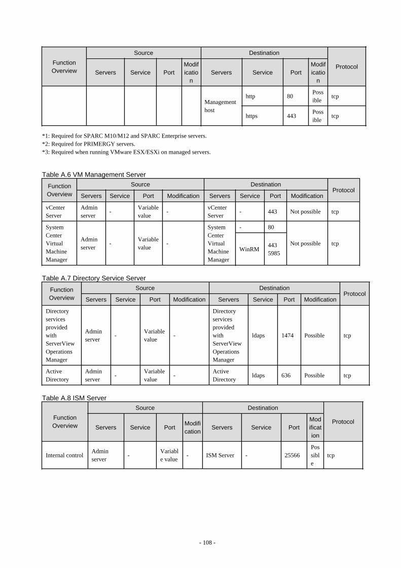
FunctionOverview
Source Destination
ProtocolServers Service Port
Modificatio
nServers Service Port
Modificatio
n
Managementhost
http 80Possible
tcp
https 443Possible
tcp
*1: Required for SPARC M10/M12 and SPARC Enterprise servers.*2: Required for PRIMERGY servers.*3: Required when running VMware ESX/ESXi on managed servers.
Table A.6 VM Management Server
FunctionOverview
Source DestinationProtocol
Servers Service Port Modification Servers Service Port Modification
vCenterServer
Adminserver
-Variablevalue
-vCenterServer
- 443 Not possible tcp
SystemCenterVirtualMachineManager
Adminserver
-Variablevalue
-
SystemCenterVirtualMachineManager
- 80
Not possible tcpWinRM
4435985
Table A.7 Directory Service Server
FunctionOverview
Source DestinationProtocol
Servers Service Port Modification Servers Service Port Modification
DirectoryservicesprovidedwithServerViewOperationsManager
Adminserver
-Variablevalue
-
DirectoryservicesprovidedwithServerViewOperationsManager
ldaps 1474 Possible tcp
ActiveDirectory
Adminserver
-Variablevalue
-ActiveDirectory
ldaps 636 Possible tcp
Table A.8 ISM Server
FunctionOverview
Source Destination
ProtocolServers Service Port
Modification
Servers Service PortModification
Internal controlAdminserver
-Variable value
- ISM Server - 25566Possible
tcp
- 108 -

Table A.9 DHCP Server
FunctionOverview
Source Destination
ProtocolServers Service Port
Modification
Servers Service PortModification
DHCP serviceAdminserver
-Variable value
Notpossible
DHCPServer
nfagent 23458Possible
tcp
tftp 69
Notpossible
udp
bootps 67
Notpossible
udp
- 109 -

Appendix B HTTPS CommunicationsThis appendix explains the HTTPS communication protocol used by Resource Orchestrator and its security features.
Resource Orchestrator uses HTTPS communication for the three cases shown in the figure below. Certificates are used for mutualauthentication and for encrypting communication data.
Figure B.1 HTTPS Communication
1. Between the Admin Client and the Admin Server, or Between the HBA address rename Server and the Admin Server
The admin client and HBA address rename server automatically obtain a certificate from the admin server at each connection. Thiscertificate is used to encrypt the communicated data.
2. Between the Admin Server and Managed Servers (Communication with Agents)
Certificates are created on both the admin server and managed servers when Resource Orchestrator (manager or agent) is firstinstalled. Certificates of other communication targets are stored at different timings, as described below (refer to "Certificate CreationTiming"). Those certificates are used for HTTPS communication based on mutual authentication.When re-installing the manager, its agent certificates (stored on the admin server) are renewed. Because the renewed certificatesdiffer from those stored on the agent side (on managed servers), agents are not able to communicate with the admin server. To avoidsuch communication issues, it is recommended to backup agent certificates (on the admin server) before uninstalling the manager,and restore them after re-installation. When re-installing the manager, back up the certificates referring to "11.1 ManagerUninstallation" in the "Setup Guide VE". When restoring the certificates, refer to "2.1 Manager Installation" in the "Setup Guide VE".
3. Between the Admin Server and Managed Servers (Communication with VM Hosts), or Between the Admin Server and VMManagement Software [VMware]
The admin server obtains and stores certificates for each connection with a managed server (VM host) or VM management software.Those certificates are used to encrypt communications.
Certificate Creation Timing
Between the Admin Client and the Admin Server, or Between the HBA address rename Server and the Admin Server
Certificates are automatically obtained each time HTTPS connections are established. They are not stored on the admin server.
Between the Admin Server and Managed Servers (Communication with Agents)
The certificates used for HTTPS communication are automatically exchanged and stored on the manager and agents on the followingoccasions:
- When registering a managed server
- 110 -
- Right after re-installing and starting an agent
Between the Admin Server and Managed Servers (Communication with VM Hosts), or Between the Admin Server and VMManagement Software [VMware]
Certificates are automatically obtained each time HTTPS connections are established. They are not stored on the admin server.
Types of Certificates
Resource Orchestrator uses the following certificates.
Between the Admin Client and the Admin Server, or Between the HBA address rename Server and the Admin Server
The public keys included in the certificates are created using X.509-based RSA encryption. These keys are 2048 bits long.
Between the Admin Server and Managed Servers (Communication with Agents)
The public keys included in the certificates are created using X.509-based RSA encryption. These keys are 2048 bits long.
Between the Admin Server and Managed Servers (Communication with VM Hosts), or Between the Admin Server and VMManagement Software [VMware]
The public keys included in the certificates are created using X.509-based RSA encryption. The key length depends on the specificationsof the VM host or the VM management software.
Adding the Admin Server's Certificate to Client Browsers
Resource Orchestrator automatically generates a unique, self-signed certificate for each admin server during manager installation. Thiscertificate is used for HTTPS communication with admin clients.Use of self-signed certificates is generally safe within an internal network protected by firewalls, where there is no risk of spoofing attacksand communication partners can be trusted. However, Web browsers, which are designed for less-secure networks (internet), will see self-signed certificates as a security threat, and will display the following warnings.
- Warning dialog when establishing a connection
When opening a browser and connecting to the admin server for the first time, a warning dialog regarding the security certificatereceived from the admin server is displayed.
- Address bar and Phishing Filter warning in Internet Explorer
The background color of the address bar will become red and the words "Certificate Error" will be displayed on its right side of theaddress bar of the login screen, the ROR console, and BladeViewer.Furthermore, the Phishing Filter may show a warning on the status bar.
When using Internet Explorer, the above warnings can be disabled by creating a certificate for the admin server's IP address or host name(FQDN) that is specified in the address bar's URL, and installing it to the browser.On the admin server, a certificate for host name (FQDN) is automatically created during installation of the manager.When using other servers as admin clients, use the following procedure to install the admin server's certificate on each client.Therefore, the certificate creation step in the following procedure can be skipped when using the admin server as an admin client. In thatcase, use host name (FQDN) in the URL and proceed to step 2.
1. Create a Certificate
a. Open the command prompt on the admin server.
b. Execute the following command to move to the installation folder.
[Windows Manager]
>cd "Installation_folder\SVROR\Manager\sys\apache\conf" <RETURN>
[Linux Manager]
# cd /etc/opt/FJSVrcvmr/sys/apache/conf <RETURN>
- 111 -

c. After backing up the current certificate, execute the certificate creation command bundled with Resource Orchestrator(openssl.exe).
When using the -days option, choose a value (number of days) large enough to include the entire period for which you plan touse Resource Orchestrator. However, the certificate's expiration date (defined by adding the specified number of days to thecurrent date) should not go further than the 2038/1/19 date.
Example
When the Manager is installed in the "C:\Fujitsu\ROR" folder, and generating a certificate valid for 15 years (or 5479 days,using the -days 5479 option)
[Windows Manager]
>cd "C:\Fujitsu\ROR\SVROR\Manager\sys\apache\conf" <RETURN>>..\..\..\bin\rcxadm mgrctl stop <RETURN>>copy ssl.crt\server.crt ssl.crt\server.crt.org <RETURN>>copy ssl.key\server.key ssl.key\server.key.org <RETURN>>..\bin\openssl.exe req -new -x509 -nodes -sha256 -newkey rsa:2048 -out ssl.crt\server.crt -keyout ssl.key\server.key -days 5479 -config openssl.cnf <RETURN>Loading 'screen' into random state - doneGenerating a 2048 bit RSA private key.................++++++................................++++++writing new private key to 'ssl.key\server.key'-----You are about to be asked to enter information that will be incorporatedinto your certificate request.What you are about to enter is what is called a Distinguished Name or a DN.There are quite a few fields but you can leave some blankFor some fields there will be a default value,If you enter '.', the field will be left blank.-----Country Name (2 letter code) []: <RETURN>State or Province Name (full name) []: <RETURN>Locality Name (eg, city ) []: <RETURN>Organization Name (eg, company) []: <RETURN>Organizational Unit Name (eg, section) []: <RETURN>Common Name (eg, server FQDN or YOUR name) [localhost]: IP_address or hostname (*) <RETURN>Email Address []: <RETURN>
>..\..\..\bin\rcxadm mgrctl start <RETURN>
[Linux Manager]
# cd /etc/opt/FJSVrcvmr/sys/apache/conf <RETURN># /opt/FJSVrcvmr/bin/rcxadm mgrctl stop <RETURN># cp ssl.crt/server.crt ssl.crt/server.crt.org <RETURN># cp ssl.key/server.key ssl.key/server.key.org <RETURN># /opt/FJSVrcvmr/sys/apache/bin/openssl req -new -x509 -nodes -sha256 -newkey rsa:2048 -out ssl.crt/server.crt -keyout ssl.key/server.key -days 5479 -config /opt/FJSVrcvmr/sys/apache/ssl/openssl.cnf<RETURN>Generating a 2048 bit RSA private key.................++++++................................++++++writing new private key to 'ssl.key/server.key'-----You are about to be asked to enter information that will be incorporatedinto your certificate request.
- 112 -

What you are about to enter is what is called a Distinguished Name or a DN.There are quite a few fields but you can leave some blankFor some fields there will be a default value,If you enter '.', the field will be left blank.-----Country Name (2 letter code) []: <RETURN>State or Province Name (full name) []: <RETURN>Locality Name (eg, city ) []: <RETURN>Organization Name (eg, company) []: <RETURN>Organizational Unit Name (eg, section) []: <RETURN>Common Name (eg, server FQDN or YOUR name) [localhost]: IP_address or hostname (*) <RETURN>Email Address []: <RETURN>
# /opt/FJSVrcvmr/bin/rcxadm mgrctl start <RETURN>
* Note: Enter the IP address to be entered in the Web browser or the host name (FQDN).
Example
IP address: 192.168.1.1Host name: myhost.company.com
2. Add the Certificate to the Web Browser
Internet Explorer
Open the Resource Orchestrator login screen, referring to "Chapter 3 Login to the ROR Console" in the "Setup Guide VE".When opening the ROR console, enter the same IP address or host name (FQDN) as that used to generate the certificate in the previousstep. Once the login screen is displayed, perform the following operations.
a. Open the [Certificate] dialog.
Open the "Certificate is invalid dialog" by clicking the "Certificate Error" displayed in the address bar in Internet Explorer. Thiswill open an "Untrusted Certificate" or "Certificate Expired" message.Click the "View certificates" link displayed at the bottom of this dialog.
b. Confirm that the "Issued to" and "Issued by" displayed in the [Certificate] dialog are both set to the IP address or host name(FQDN) used to generate the certificate.
c. In the [Certificate] dialog, click [Install Certificate].
The [Certificate Import Wizard] dialog is displayed.
d. Click [Next>].
e. Select "Place all certificates in the following store".
f. Click [Browse].
The [Select Certificate Store] dialog is displayed.
g. Select "Trusted Root Certification Authorities".
h. Click [OK].
i. Click [Next>].
j. Check that "Trusted Root Certification Authorities" is selected.
k. Click [Finish].
l. Restart the Web browser.
If multiple admin clients are used, perform this operation on each admin client.
- 113 -

Firefox
Open the Resource Orchestrator login screen, referring to "Chapter 1 Login and Logout" in the "User's Guide VE".
If the [This Connection is Untrusted] window is displayed, perform the following procedure:
a. Select <I Understand the Risks> and click the <Add Exception> button.The [Add Security Exception] window is displayed.
b. In the [Add Security Exception] window, click the <View> button. The[Certificate Viewer] is displayed.
c. In the [Certificate Viewer], ensure that the certificate and the issuer have an IP address or hostname (FQDN) specified.
d. In the [Add Security Exception] window, click the <Confirm Security Exception> button.
After logging in and clicking a tab, the [This Connection is Untrusted] window may be displayed.
If this occurs, perform the following procedure:
a. In the [Options] window, click the <Advanced>, and then the <Encryption> tab.
b. Click the <View Certificates> button.The [Certificate Manager] window is displayed.
c. Select the <Servers> tab, and then click the <Add Exception> button.The [Add Security Exception] window is displayed.
d. In the [Add Security Exception] window, enter the URL displayed in the [This Connection is Untrusted] window, and thenclick <Get Certificate>.
e. Click the <View> button to display the [Certificate Viewer].
f. In the Certificate Viewer, ensure that the certificate and the issuer have an IP address or hostname (FQDN) specified.
g. In the [Add Security Exception] window, click the <Confirm Security Exception> button.
h. Click the <OK> button.
Note
- Enter the IP address or host name (FQDN) used to generate the certificate in the Web browser's URL bar. If the entered URLdiffers from that of the certificate, a certificate warning is displayed.
Example
A certificate warning is displayed when the following conditions are met.
- The entered URL uses an IP address while the certificate was created using a host name (FQDN)
- The admin server is set with multiple IP addresses, and the entered URL uses an IP address different from that used to generatethe certificate
- When using Firefox on Windows OS, the certificate needs to be installed to the OS via Internet Explorer.
- 114 -

Appendix C Hardware ConfigurationThis appendix explains how to configure hardware.
C.1 Connections between Server Network Interfaces and LANSwitch Ports
Configuring VLAN settings on internal LAN switch ports requires an understanding of the network connections between LAN switches andphysical servers (between LAN switch ports and the network interfaces mounted in each server).This section shows which network interfaces (on PRIMERGY BX600 server blades) are connected to which LAN switch blade ports.For servers other than PRIMERGY BX servers, refer to the server manual for details on the connections between server blades and LANswitch blades.The connections between server blades and LAN switch blades are shown in the following table.
Table C.1 Connections between Server Blades and LAN Switch Blades (PG-SW107)
NIC index NIC placement (on a server blade)Connected port number (on a LAN
switch blade)
Index 1 Onboard LAN1 NET1 port "3N-2"
Index 2 Onboard LAN2 NET2 port "3N-2"
Index 3 Onboard LAN3 NET1 port "3N-1"
Index 4 Onboard LAN4 NET2 port "3N-1"
Index 5 Onboard LAN5 NET1 port "3N"
Index 6 Onboard LAN6 NET2 port "3N"
Index 7 LAN expansion card LAN1 NET3 port "N"
Index 8 LAN expansion card LAN2 NET4 port "N"
N: Slot number of the connected server blade
PG-SW104/105/106 is mounted in NET3 and NET4.For details, refer to the chassis hardware manual.
Table C.2 Connections between Server Blades and LAN Switch Blades (PG-SW104/105/106)
NIC index NIC placement (on a server blade)Connected port number (on a LAN
switch blade)
Index 1 Onboard LAN1 NET1 port "N"
Index 2 Onboard LAN2 NET2 port "N"
Index 3 LAN expansion card LAN1 NET3 port "N"
Index 4 LAN expansion card LAN2 NET4 port "N"
Index 5 - -
Index 6 - -
Index 7 - -
Index 8 - -
-: NoneN: Slot number of the connected server blade
- 115 -

Note
VLAN settings cannot be configured on the following devices.
- PRIMERGY BX600 Ethernet Blade Panel 1Gb 10/6 (IBP 10/6) and 30/12 (IBP 30/12)
- A LAN switch directly connected to a PRIMERGY BX 600 LAN pass-thru blade
- A LAN switch directly connected to servers other than PRIMERGY BX servers
LAN switch blade product names may differ between countries.This section refers to the product names used in Japan.The following table shows product references often used in other countries.
Reference Product Name
PG-SW104PRIMERGY BX600 Switch Blade (1Gbps)PRIMERGY BX600 Ethernet Switch 1GB 10/6(SB9)
PG-SW105PRIMERGY BX600 Switch Blade (10Gbps)PRIMERGY BX600 Ethernet Switch 1GB 10/6+2(SB9)
PG-SW106Cisco Catalyst Blade Switch 3040PRIMERGY BX600 Ethernet Switch 1GB 10/6(Cisco CBS 3040)
PG-SW107PRIMERGY BX600 Switch Blade (1Gbps)PRIMERGY BX600 Ethernet Switch 1GB 30/12(SB9F)
C.2 WWN Allocation Order during HBA address renameConfiguration
This section explains the order in which WWNs are allocated during configuration of HBA address rename.
With HBA address rename, as WWNs are allocated to the I/O addresses of HBAs in descending order, the order may not match the portorder listed in the HBA.When specifying the locations for WWN allocation, check the I/O addresses of HBAs.The I/O addresses of HBAs can be confirmed using tools provided by HBA vendors or FC-HBA BIOS.
- For blade servers
Example
For a blade server with an HBA with 2 ports, allocation is performed as follows:
WWN value provided by "I/O Virtualization Option": 20:00:00:17:42:51:00:00
WWNN value for ports 1 and 2 of the HBA : 20:00:00:17:42:51:00:00
WWPN value for HBA port 1 : 9:00:00 PM:17:42:51:00:00
WWPN value for HBA port 2 : 10:00:00 PM:17:42:51:00:00
- For rack mount or tower servers
For the PCI slots of rack mount or tower servers, WWNs are allocated in the following order:
PRIMERGY RX200 S4 slot2 -> slot1 -> slot3
PRIMERGY RX200 S5 or later slot1 -> slot2 -> slot3
PRIMERGY RX300 S4 slot5 -> slot6 -> slot1 -> slot7 -> slot4 -> slot2 -> slot3
PRIMERGY RX300 S5 or later slot2 -> slot3 -> slot4 -> slot5 -> slot6 -> slot7 -> slot1
PRIMERGY RX600 S4 slot6 -> slot3 -> slot4 -> slot1 -> slot2 -> slot7 -> slot5
PRIMERGY RX600 S5 slot7 -> slot6 -> (slot5 -> slot8 -> slot9 -> slot10) -> slot4 -> slot3 -> slot2
-> slot1
PRIMERGY RX600 S6 slot7 -> slot6 -> (slot5 -> slot8 -> slot9 -> slot10) -> slot4 -> slot3 -> slot2
-> slot1
- 116 -

PRIMERGY RX2520 M1 slot4 -> slot5 -> slot6 -> slot2 -> slot3 -> slot1
PRIMERGY RX4770 M1 slot9 -> slot8 -> slot10 -> slot5 -> slot6 -> slot7 -> slot4 -> slot3 -> slot2
-> slot1
PRIMERGY TX300 S4 slot5 -> slot6 -> slot1 -> slot7 -> slot4 -> slot2 -> slot3
PRIMERGY TX300 S5 (slot7) -> slot6 -> slot5 -> slot4 -> slot3 -> slot2 -> (slot1)
PRIMERGY TX300 S6 slot5 -> slot6 -> slot1 -> slot7 -> slot4 -> slot2 -> slot3
In a single PCI slot, allocate WWNs in the following order:
port 2 -> port 1
Example
When one port HBAs are mounted in slot 2 and slot 3 of an RX600 S4, WWNs are allocated in the following order:
slot 3 -> slot 2
WWN value provided by "I/O Virtualization Option": 20:00:00:17:42:51:00:00
WWNN value for slots 2 and 3 of the HBA : 20:00:00:17:42:51:00:00
WWPN value for HBA slot 2 : 22:00:00:17:42:51:00:00
WWPN value for HBA slot 3 : 21:00:00:17:42:51:00:00
When two port HBAs are mounted in slot 2 of an RX600 S4, WWNs are allocated in the following order:
slot 2 (port 2) -> slot 2 (port 1)
WWN value provided by "I/O Virtualization Option": 20:00:00:17:42:51:00:00
WWNN value for ports 1 and 2 of the HBA : 20:00:00:17:42:51:00:00
WWPN value for HBA port 1 : 10:00:00 PM:17:42:51:00:00
WWPN value for HBA port 2 : 9:00:00 PM:17:42:51:00:00
- 117 -

Appendix D Ethernet Fabric DevicesThis appendix explains the method for managing Ethernet fabric devices in Resource Orchestrator.
D.1 Fujitsu PRIMERGY Converged Fabric Switch Blade (10 Gbps18/8+2) and Fujitsu Converged Fabric Switch
This section explains the method for managing Ethernet fabric configured using "Fujitsu PRIMERGY Converged Fabric Switch Blade (10GPS 18/8+2)" and "Fujitsu CFX 2000 Series".
D.1.1 Management UnitThe configuration example of the Ethernet fabric configured using "Fujitsu PRIMERGY Converged Fabric Switch Blade (10 GPS 18/8+2)"and "Fujitsu CFX 2000 Series" is shown in "Figure D.1 Network Device Management Unit".
Resource Orchestrator manages all devices comprising an Ethernet fabric as a single network device.
Figure D.1 Network Device Management Unit
- 118 -

D.2 Extreme VCS FabricThis section explains Ethernet fabrics (VCS) configured for ExtremeSwitching VDX series.
D.2.1 Management UnitA configuration example of Ethernet fabrics (VCS) configured for ExtremeSwitching VDX series is shown in "Figure D.2 Network DeviceManagement Unit".
Resource Orchestrator manages all devices comprising an Ethernet fabric (VCS) as a single network device.
Note
Display of the Virtual Fabric is not supported.
Figure D.2 Network Device Management Unit
- 119 -

Appendix E IPCOM VX Series DevicesThis appendix explains the method for managing IPCOM VX series devices in Resource Orchestrator.
E.1 IPCOM VX SeriesThis section explains how to manage IPCOM VX series devices configured for linking with Ethernet fabrics.
E.1.1 Management UnitA configuration example of IPCOM VX series configured for linking with Ethernet fabrics is shown in "Figure E.1 Network Device(IPCOM VX Series) Management Unit".
Resource Orchestrator manages IPCOM VX series devices as a single management host network device. Each IPCOM VA in an IPCOMVX series device is managed as a network device (firewall or server load balancer).
For the port name of the Ethernet fabric to specify for the link information of the network configuration information necessary forregistration as a network device, specify an IEEE802.1ad frame communication port with the type EP (End Point) and CIR (Clean Interfacewith Redundancy). The port type can be either EP or CIR.
For details on how to confirm the port name to specify, refer to "7.7.3 Creating Network Configuration Information (XML Definition)".
For the admin IP address to specify when stating the network device information in the network configuration information, specify theadmin IP address configured for the IPCOM VX series device or IPCOM VA.
The following configuration diagram is based on the assumption that the VFAB is set to network mode.
- 120 -

Figure E.1 Network Device (IPCOM VX Series) Management Unit
- 121 -


