Embed Size (px)
Citation preview

for midas CivilDESIGN GUIDE
CAN/CSA S6-14
Prestressed Concrete Girder Design
Steel Composite I-Girder Design
Steel Composite Box Girder Design


Developers and distributors assume no responsibility for the use of MIDAS Family Program (midas Civil, midas FEA, midas FX+, midas Gen, midas Drawing, midas SDS, midas
“MIDAS package”) or for the accuracy or validity of any results obtained from the MIDAS package.
Developers and distributors shall not be liable for loss of
caused directly or indirectly by the MIDAS package, when used for any purpose or use, due to any defect or
fully understand the bases of the program and become familiar with the users manuals. The user shall also inde-pendently verify the results produced by the program.
DISCLAIMER
analysis and design system. The guide aims to provide
features and to provide relevant references to the clauses in the Design standards.
The design guide covers prestressed concrete girder, steel composite I-girder and steel composite box girder as per CAN/CSA S6-14.
It is recommended that you read this guide and review corresponding tutorials, which are found on our web site,
the program’s main menu.

girder design to CAN/CSA S6-14.
design to CAN/CSA S6-14.
design to CAN/CSA S6-14.
Organization
features and to provide relevant references to the clauses in the Design standards.
The design guide covers prestressed concrete girder, steel composite I-girder and steel composite box girder as per CAN/CSA S6-14.
It is recommended that you read this guide and review corresponding
help available in the program’s main menu.
Foreword

Steel Composite I - Girder Design (CAN/CSA-S6-14)Chapter 2. 471. CAN/CSA S6-14 Steel Composite I-Girder 49
51
51
1. Composite I Girder
2. Shear Connector
4. Horizontally curved Box girders
72
86
88
94
Modeling and Design Variables1. Modeling Design Variables 55
Contents
Prestressed Concrete Girder Design (CAN/CSA-S6-14) 01Strength Limit States1. Flexural resistance
2. Shear resistance
3. Torsion resistance
03
14
21
Serviceability Limit States
3. Tensile stress for Prestressing tendons
5. Principal stress at service loads (Excluding torsional shear stress)
6. Principal stress at service loads
26
31
34
37
39
40
7. Check crack 42

Steel Composite Design Result97
100
101
103
104
105
7. Total Checking 106
Steel Composite Design Result163
166
167
169
170
171
7. Total Checking 172
Steel Composite Box Girder Design (CAN/CSA S6-14)Chapter 3. 1071. CAN/CSA S6-14 Steel Composite Box Girder 109
111
111
1. Composite Box Girder
2. Shear Connector
4. Horizontally curved Box girders
Box Girder
132
148
150
158
Modeling and Design Variables1. Modeling Design Variables 115

Prestressed ConcreteGirder Design
CAN/CSA S6 -14
Chapter 1.
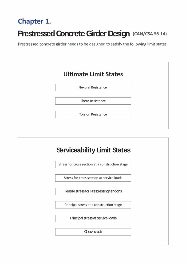
Prestressed Concrete Girder Design
Serviceability Limit States
Tensile stress for Prestressing tendons
Principal stress at service loads
Check crack

Chapter 1. Prestressed Concrete Girder Design : CSA-S6-14
Strength Limit State
3Chapter 1. Prestressed Concrete Girder Design
1. Flexural resistance For the flexural resistance design limit, Mf ≤Mr shall be satisfied where Mf : factored moment at a section
Mr : factored flexural resistance of a section in bending
1.1 Material resistance factors
[Fig.1. 1] Material resistance factors
In CSA, regardless of applied members, resistant forces are calculated with the corresponding material resistance factors.
1.2 Calculate neutral axis depth. (by Iteration approach) Neutral axis is iteratively calculated by the following steps.
Assume neutral axis depth, c
Calculate Cc (Concrete)
Calculate Ts, Cs (Reinforcement)
Calculate Tps (Tendon)
Cc+Cs-(Ts+Tps)=0?
Get neutral axis depth, c
YES
NO
(1)
(2)
(3)
(4)
Initial c = H/2 (H=Section Height)
[Fig.1. 2] Flow chart to calculate neutral axis depth, c
CAN/CSA-S6-14 (8.4.6)

4 Design Guide for midas Civil
(1) Calculate force of concrete, Cc. midas Civil assumes a rectangular stress distribution in the stress and strain relationship of concrete. Note that the maximum strain is assumed εcu = 0.0035
[Fig.1. 3] Flow chart to calculate neutral axis depth, c
1 'c c c cC f A (1.1)
where
1 0.85 0.0015 ' 0.67cf
c : Material resistance factors for concrete
'cf : Specified compressive strength of concrete
cA : Concrete area of compressive zone 1( )ab c b
1 0.97 0.0025 ' 0.67cf c : Distance from the extreme compression fiber to the neutral axis. b : Width f’c value applied in calculation is inputted as shown below.
PSC>PSC Design Data> PSC Design Material…
[Fig.1. 4] PSC Design Material
Concrete and reinforcement data are entered in the PSC Design Materials dialog box. Selection of design standard and the type of concrete to be used determine the Specified Compressive Strength, which is the f’c value in PSC design.
CAN/CSA-S6-14 (8.8.3)
Concrete Material Property
Reinforcement Material Property

5 Chapter 1. Prestressed Concrete Girder Design
Similarly for concrete, selection of design standard and the type of steel to be used determine the yield stress for longitudinal reinforcements and shear reinforcements, and these values are used in PSC design. Input tendon profile data for PSC design in the dialog box below.
Load>Temp./Prestress>Section Manager >Tendon Profile
Tendon data can be entered in the 2D or 3D coordinate system. Tendon position which is placed at the farthest position from the extreme compression fiber will be used to calculate the strain.
Input longitudinal reinforcement data for PSC design in the dialog box below.
Properties>Section Manager>Reinforcements
[Fig.1. 6] Input Longitudinal reinforcement
Once reinforcement is entered at the PSC section, the rebar which is placed at the farthest position from the extreme compression fiber will be used to calculate the strain. In short, the rebar at the bottom most is used under the sagging moment while the rebar at the top most is used under the hogging moment.
Entered rebar data
Rebar coordinate at section
[Fig.1. 5] Tendon Profile

6 Design Guide for midas Civil
(2) Calculate force of reinforcement, Ts, Cs.
, ' 's s s s s s s sT A f C A f (1.2)
where Φs : Material resistance factor for steel As, As’ : the cross sectional area of tensile and compressive reinforcements. fs , fs’: the stress of tensile and compressive reinforcements.
In order to calculate the tensile stress of reinforcements at a section, strain of the reinforcements is first obtained based on the strain compatibility condition. The corresponding stresses are then computed by the stress-strain relationship. The equations are shown below. Strain
cut
s xxd , cu
cs x
dx' (1.3)
where εs : the strain of tensile reinforcement. εs’ : the strain of compressive reinforcement.
εcu : the ultimate compressive strain in the concrete. (εcu = 0.0035) x : the neutral axis depth. dt : distance from the extreme compression fiber to the rebar at the bottom most dc : distance from the extreme compression fiber to the rebar at the top most
Stress
Once the yield stress is reached, the yield stress is applied for stress in steel. εs x Es is, otherwise, used.
( )( )
s s s ys
y s y
E f ff
f f f,
' ( ' )'
( ' )s s s y
sy s y
E f ff
f f f (1.4)
where Es : Elastic modulus of steel Fy : Yield stress of steel
(3) Calculate force of tendon, Tps.
ps p p psT A f (1.5)
where Φp : Material resistance factors for tendon Ap : the cross sectional area of tendon fps : the stress of tendon.

7 Chapter 1. Prestressed Concrete Girder Design
Tendon-related data can be entered in the Tendon Property dialog box.
Load>Temp./Prestress>Section Manager>Tendon Property
[Fig.1. 7] Tendon Property Dialog
Tendon Type
Select one among Pre-Tension, Post-Tension, and External Tension. Internal(Pre-Tension) : Tendon is tension-stressed prior to the placement of concrete and unloaded after the concrete has hardened. This introduces compression through adhesive bonds between concrete and tendon. Internal(Post-Tension) : Compression is introduced by tensioning tendons after concrete has hardened. The tendons are wedged after achieving a desired level of stress. External : Tendons are placed external to concrete members and stressed
Bond Type
Bonded : This defines a perfect bond between concrete and tendon. The case of Internal(Pre-Tension) defines the Bond Type as Bonded. Unbonded : In this case, tendon is not well bonded with concrete, allowing relative movements to the concrete. The case of External defines the bond Type as Unbonded.
Bond type can be classified as shown in Table1.1 below, depending on the Tendon Type. [Table1. 1] Bond Type Depending on Tendon Type
Tendon Type Bond Type
Internal (Pre-tension) Bonded
Internal (Post-tension) Bonded
Unbonded
External Unbonded Total Tendon Area
Enter the area of Tendon (Ap).
Select the number of tendon cable and the size o f its diameter via button.
fpu, fpy Enter the ultimate strength fpu and yield strength fpy of the prestressing steel.
Stress fps differs depending on the Bond Type. For the case of the Bonded Type, depending on the ratio c/dp, fps is calculated differently as well.
CAN/CSA-S6-14 (8.8.4.2)
Total Tendon Area
fpu fpy
Bond Type
Tendon Type

8 Design Guide for midas Civil
[Table1. 2] calculation method of fps Bond Type Classification Tensile stress
Bonded Type c/dp ≤0.5 Bonded Type fps c/dp >0.5 Strain compatibility
Unbonded Type - Unbonded Type fps
Where c: Distance between the neutral axis and the compressive face
dp : Distance from the extreme compression fiber to the centroid of the prestressing tendons
fps in Bonded Type
1ps pu pp
cf f k
d (1.6)
where Kp : 0.3 for low-relaxation strands 0.4 for smooth high-strength bars 0.5 for deformed high-strength bars fpu : Specified tensile strength of tendon (MPa)
Tendon Type can be assigned as shown in a red box below.
PSC> Design Parameter> Parameters…
[Fig.1. 8] PSC Design Parameter Dialog – Tendon Type
For clarification, notations used in a Civil dialog and in Design Code are summarized in Table1.3. [Table1. 3] Tendon Type
Civil Dialog Design Code
Low Relaxation Tendons Low Relaxation Strand
Stress Relieved Tendons smooth high-strength Bar
Prestressing Bar deformed high-strength Bar

9 Chapter 1. Prestressed Concrete Girder Design
fps in Unbonded Type
ps sef f (1.7)
where fse : effective stress in prestress steel after losses fps by Strain compatibility
When bending strength is calculated using strain compatibility condition, Stress-strain equation of Tendon is used.
When εp ≤ 0.008 : fps = Epεp When εp > 0.008 :
(Grade 1760 Strands) 0.4331749 0.980.00614ps pu
p
f f (1.8)
(Grade 1860 Strands) 0.5171848 0.98
0.0065ps pup
f f
(4) Check if a resultant force is Zero.
Until equilibrium between compressive forces (C=Cc+Cs) and tensile forces(T=Ts+Tps) is satisfied within a certain level of convergence criterion, iterative calculations are performed by changing the c value. Convergence criterion is applied as shown in the following equation • Convergence condition :
1.0 0.001 ( )CTolerance
T (1.9)
1.3 Calculate moment resistance (Mr) Once the neutral axis is computed, the axial forces obtained in 1.2.1(1)~(3) are multiplied by the distance from their individual acting point to the neutral axis. These obtained moments are summed to obtain the total moment resistance Mr.
'r c c s s s s ps piM C a C a T a T a (1.10)
where ac, as, as’, api : the distance from neutral axis depth, c to concrete, reinforcement rebar, tendon.
As
As
Ap
Cs
Cc
Ts
Tps
0.85f c
ac
a s a p
a c a s'
[Fig.1. 9] Forces and distances from neutral axis depth for Mn
CAN/CSA-S6-00 (C 8.8.3.2)
10 Design Guide for midas Civil
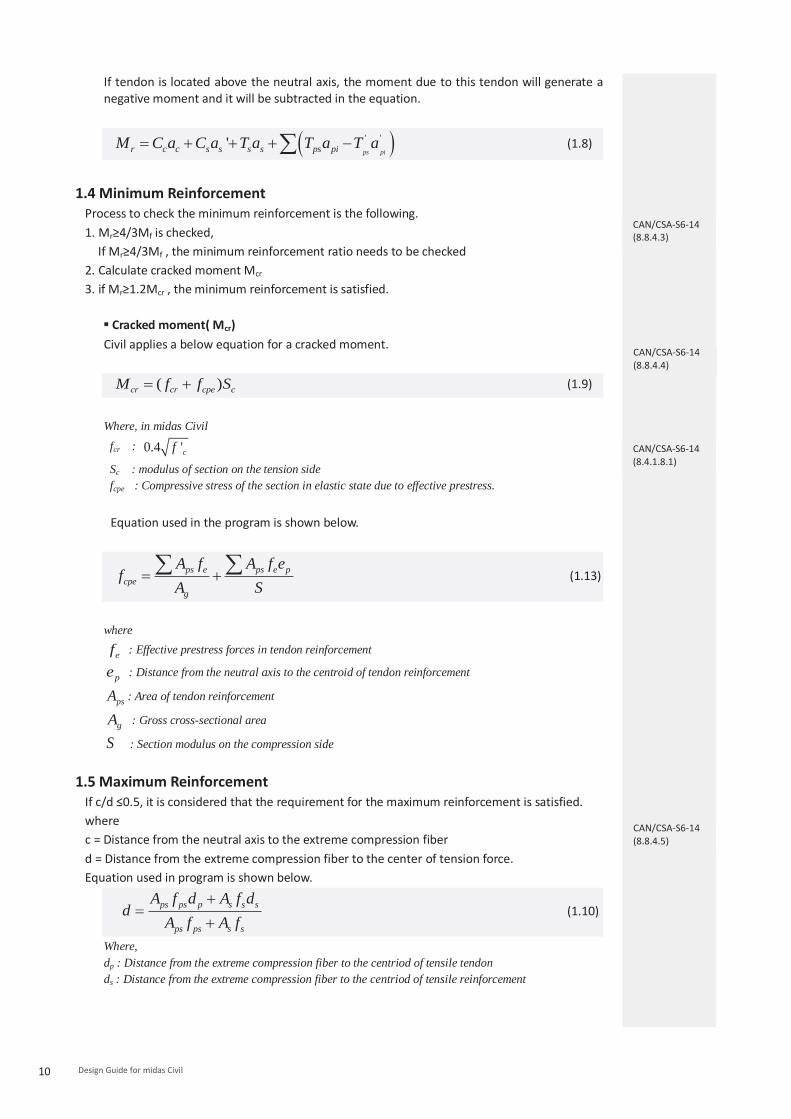
If tendon is located above the neutral axis, the moment due to this tendon will generate a negative moment and it will be subtracted in the equation.
' ''ps pir c c s s s s ps piM C a C a T a T a T a
(1.8)
1.4 Minimum Reinforcement
Process to check the minimum reinforcement is the following. 1. Mr≥4/3Mf is checked,
If Mr≥4/3Mf , the minimum reinforcement ratio needs to be checked 2. Calculate cracked moment Mcr 3. if Mr≥1.2Mcr , the minimum reinforcement is satisfied.
Cracked moment( Mcr) Civil applies a below equation for a cracked moment.
( )cr cr cpe cM f f S (1.9)
Where, in midas Civil
fcr : 0.4 'cf
Sc : modulus of section on the tension side fcpe : Compressive stress of the section in elastic state due to effective prestress.
Equation used in the program is shown below.
ps e ps e pcpe
g
A f A f ef
A S (1.13)
where
ef : Effective prestress forces in tendon reinforcement
pe : Distance from the neutral axis to the centroid of tendon reinforcement
psA : Area of tendon reinforcement
gA : Gross cross-sectional area
S
: Section modulus on the compression side
1.5 Maximum Reinforcement If c/d ≤0.5, it is considered that the requirement for the maximum reinforcement is satisfied. where c = Distance from the neutral axis to the extreme compression fiber d = Distance from the extreme compression fiber to the center of tension force. Equation used in program is shown below.
ps ps p s s s
ps ps s s
A f d A f dd
A f A f (1.10)
Where, dp : Distance from the extreme compression fiber to the centriod of tensile tendon ds : Distance from the extreme compression fiber to the centriod of tensile reinforcement
CAN/CSA-S6-14 (8.8.4.3)
CAN/CSA-S6-14 (8.4.1.8.1)
CAN/CSA-S6-14 (8.8.4.4)
CAN/CSA-S6-14 (8.8.4.5)

11 Chapter 1. Prestressed Concrete Girder Design
1.6 Check Component of Flexural Resistance If c/dp > 0.5, it is considered that the calculated flexural resistance can be ignored. The users can check the results with the table. There is the calculated value for c/dp, and if c/dp > 0.5, it will be shown with dash(-).
The tendon stress (fps) will be calculated by fps equation of Bonded type, depending on the value for c/dp.
1.7 Check moment resistance
The user needs to select load combination cases to be used to check the strength limit with respect to bending moments as shown in Figure1.10.
Results>Load combinations>Concrete Design tab
[Fig.1. 10] Load Combinations dialog
Load combinations for PSC design can be entered within the Concrete Design tab of the Load Combination dialog. For load combinations with Strength/Stress defined in the Active column, bending strength is checked in terms of positive and negative bending moments. In addition, these load combinations are applied to check strength limits for shear and twist. For load combinations with Serviceability defined in the Active column, serviceability limits are checked. There are two cases to be considered in the verification of moment
▪ When not required to satisfy minimum reinforcement requirements Mr≥Mu and (c/d≤0.5) need to be satisfied.
▪ When required to satisfy minimum reinforcement requirements Mr≥Mu, Mr≥Mcr and (c/d≤0.5) need to be satisfied.
Active: Strength/Stress
Active: Serviceability

12 Design Guide for midas Civil
1.8 Moment resistance verification
1.8.1 by Result Tables The results can be checked as shown in the table below.
Design>PSC Design>PSC Design Result Tables>Check Flexural Strength…
[Fig.1. 11] Result table for moment resistance
Elem : Element number Part : Check location (I-End, J-End) of each element. Positive/Negative : Positive moment, negative moment. LCom Name : Load combination name. Type : Displays the set of member forces corresponding to moving load case or settlement load case for which the maximum stresses are produced. CHK : Flexural strength check for element Mf : factored moment Mcr : Cracked Moment Mr : factored flexural resistance Ratio : Mf/ Mr, (less than 1, ok) min(4/3Mf, 1.2Mcr)/Mr : verification of minimum reinforcement ratio(less than 1, ok) C/D : verification of maximum reinforcement ratio (less than 0.5, ok) c/dp : Component of Flexural Resistance CHK(less than 0.5, ok)

13 Chapter 1. Prestressed Concrete Girder Design
1.8.2 by Excel Report Detailed verification results with the basis of calculation can be checked in an excel report as shown in Figure 1.12.
Design>PSC Design>PSC Design Calculation…
[Fig.1. 12] Excel Report for moment resistance

14 Design Guide for midas Civil
2 Shear resistance Pure shear without the effects of torsion is verified with the following equation. (for shear with the effects of torsion, refer to 1.3 Torsion resistance) Limit state of Shear resistance needs to satisfy Vf ≤Vr. Where Vf = factored Shear force
Vr = factored Shear resistance
2.1 Parameters for shear
2.1.1 Effective web width(bv) Effective web width (bv) is taken as web thickness. For PSC multi-cell girder, web thickness can be automatically taken as a summation of thickness for all webs. Also this value can be entered by the user directly as shown in the figure below.
Property > Section Property > Section >PSC
[Fig.1. 13] Effective web width
1) When the user directly enters values for web thickness Apply the minimum value among the entered web thickness values. 2) When “Auto” option is selected Apply the minimum web thickness among t1, t2, and t3. These values are automatically taken as
a summation of thickness for both webs at the stress point, Z1, Z2, and Z3.
2.1.2 Effective shear depth (dv) Effective shear depth is considered as follows.
min 0.9 , 0.72vd d h (1.11)
CAN/CSA-S6-14 (8.9.1.5)

15 Chapter 1. Prestressed Concrete Girder Design
where
ps ps p s s s
ps ps s s
A f d A f dd
A f A f
dp : Distance from the extreme compression fiber to the centroid of tendon reinforcements ds : Distance from the extreme compression fiber to the centroid of tensile reinforcements
2.1.3 Longitudinal strain (εx)
Longitudinal strain εx is computed with the following equation.
/ 0.52( )
f v f p f ps fpox
s s p ps
M d V V N A f
E A E A (1.12)
where Vf and Mf are positive Mf ≥ (Vf-Vp)dv Nf is posive for tension and negative for compression fpo is 0.7fpu for the bonded type, and is equal to fpe for the unbounded type εx is bounded inbetween : 0 0.003x As and Aps are the area of tensile reinforcements and tendon reinforcements, respectively
2.2 The factored shear resistance, Vn Vn is determined as the lesser of the results from Equations 1.15 and 1.16.
r c s pV V V V
(1.13)
'0.25r c c v v pV f b d V
(1.14)
Where Φc : Material resistance factors for concrete Vc : factored shear resistance by concrete Vs : factored shear resistance by shear reinforcement Vp : shear resistance component in the direction of the applied shear of the effective prestressing
force.
In midas Civil, shear resistance due to prestressing force, Vp, includes primary prestress force. The secondary effects from prestressing shall be included in the design shear force obtained from the load combinations.
2.3 The factored shear resistance by concrete, Vc
2.3.1 Determination β and Φ by general method
Design for shear allows to use two methods (Simplified method and General method) to calculate β and Φ. In midas Civil, the general method is applied.
0.4 13001 1500 1000x zeS
(1.15)
(29 7000 ) 0.882500
zex
S (1.20)
CAN/CSA-S6-14 (8.9.3.3)
CAN/CSA-S6-14 (8.9.3.7)

16 Design Guide for midas Civil
where
,min300 ( )ze v vS mm A A
,min
35 0.85 ( )15
zz v v
g
SS A A
a
Sz : dv (refer to clause 8.9.3.6) ag : 25.4mm (f’c ≤ 60Mpa)
0mm (f’c ≥ 70Mpa) 60~70 by linear interpolation (60MPa < f’c < 70Mpa) * 25.4mm is taken as an equivalent value of 1inch used in AASHTO standard.
[Fig.1. 14] θ and dv for shear
2.3.2 Vc
2.5c c cr v vV f b d (1.21)
where min(0.4 ' , 3.2 )cr cf f MPa
2.4 The factored shear resistance by transverse reinforcement, Vs
The angle of inclination of transverse reinforcements is considered in the calculation of the factored shear resistance by transverse reinforcement, Vs.
(cot cot )sins v y vs
A f dV
s (1.16)
where α = Enter the angle of transverse reinforcement as shown in Fig1.14 s = Enter the spacing as shown in Fig1.14
CAN/CSA-S6-14 (8.9.3.4)
CAN/CSA-S6-14 (8.9.3.5)

17 Chapter 1. Prestressed Concrete Girder Design
Properties>Section Manager>Reinforcements
[Fig.1. 15] Diagonal Reinforcement
Transverse reinforcement data are entered as follows. - Pitch : spacing of transverse reinforcements - Angle : angle of inclination of transverse reinforcements - Aw : total area of all transverse reinforcements in the web
2.5 Minimum amount of transverse reinforcement
,min 0.15 vv cr
y
b sA f
f (1.17)
Where,
0.4 'cr cf f
Compare the calculated Av,min with the Aw shown in Fig.1.15. If Av,min > Aw, which means the requirement is not satisfied, a message “NG” (not good) is printed in the report.
2.6 Maximum spacing for transverse reinforcement (smax)
The maximum spacing of transverse reinforcement can be checked according to the following steps:
1. Below equation is checked.
0.20 0.5f c cr v v p pV f b d V
(1.24)
Where,
min(0.4 ' , 3.2 )cr cf f MPa
2. If the above equation is applicable, then transverse reinforcements are required and the maximum spacing(smax) needs to be computed.
3. Compare the calculated smax with the entered s. If s > smax, which means the requirement is not satisfied, a message “NG” (not good) is printed in the report.
CAN/CSA-S6-14 (8.9.1.2)
CAN/CSA-S6-14 (8.9.1.3)
Transverse reinforcement
data

18 Design Guide for midas Civil
The maximum spacing(smax) for transverse reinforcements is computed with the following equation.
max min(0.33 ,300 ) (0.1 ' )v c c v v p fs d mm f b d V V (1.25)
min(0.75 ,600 ) (0.1 ' )v c c v v p fd mm f b d V V
2.7 Longitudinal reinforcement Check
Flexural Tension Side
It is verified if tensile reinforcements and tendons are capable enough to resist applied
tension induced by bending moment and shear forces.
0.5 ( 0.5 )cotflt f f s p
v
MF N V V V
d (1.26)
t p ps ps s s sF A f A f
(1.18)
If Ft ≥ Flt , OK
Flexural Compression Side
It is verified if compressive reinforcements are capable enough to resist applied
compression induced by bending moment and shear forces.
0.5 ( 0.5 )cot flc f f s p
v
MF N V V V
d (1.19)
' 'c s s sF A f (1.20)
If Fc ≥ Flc , OK
CAN/CSA-S6-14 (8.9.3.11)
CAN/CSA-S6-14 (8.9.3.12)

19 Chapter 1. Prestressed Concrete Girder Design
2.8 Interface shear Check midas Civil checks if the shear-friction reinforcement of the girder can resist against the shear force generated between the girder and the slab for the composite section.
PSC > PSC Design > Interface Shear midas Civil calculates Vri_Concrete and compare with Vfi. If Vri_Concrete > Vfi, the concrete can resiste against the shear force. In case that the concrete fail to resiste against the shear-friction force, midas Civil calculates the Shear-friction reinforcement, Vri_reinforcement and compare with Vfi. If Vri_reinforcement > Vfi, the reinforcement can resist against the shear force.
2.9 Check shear resistance
midas Civil checks the shear strength limit state for the Vmax and Vmin cases among the Active: Strength/Stress load combinations, which are defined in the Load Combinations dialog as in Fig.1.10.
2.10 Check Shear resistance results
2.10.1 by Result Tables
Shear resistance results can be checked as shown in the table below
Design>PSC Design>PSC Design Result Tables>Check Shear Strength…
[Fig.1. 16] Result table for shear resistance
Elem : Element number Part : Check location (I-End, J-End) of each element Max./Min. : Maximum shear, minimum shear LCom. Name : Load combination name. Type : Displays the set of member forces corresponding to moving load case
or settlement load case for which the maximum stresses are produced. CHK : Shear strength check for element Vf : Maximum shear force among Strength/Stress load combinations Vc : factored shear resistance by concrete Vs : factored shear resistance by shear reinforcement Vp : Shear force of the effective prestressing force Ft : Tension resistant force by tensile reinforcements and tendon Fc : Compression resistant force by compressive reinforcements

20 Design Guide for midas Civil
Flt : Tension developed due to bending moment and shear forces Flc : Compression developed due to bending moment and shear forces Vui : Interface Shear force Vri : Shear resistance force of concrete or shear-friction reinforcement Interface Shear CHK : Interface shear check
2.10.2 by Excel Report
Detailed results with basis of calculation can be found in an excel report.
Design>PSC Design>PSC Design Calculation…
[Fig.1. 17] Excel report table for shear resistance
21 Chapter 1. Prestressed Concrete Girder Design
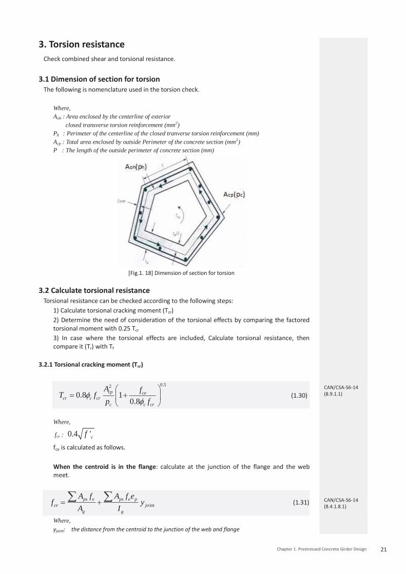
3. Torsion resistance Check combined shear and torsional resistance.
3.1 Dimension of section for torsion The following is nomenclature used in the torsion check.
Where, Aoh : Area enclosed by the centerline of exterior
closed transverse torsion reinforcement (mm2) Ph : Perimeter of the centerline of the closed tranverse torsion reinforcement (mm) Acp : Total area enclosed by outside Perimeter of the concrete section (mm2) P : The length of the outside perimeter of concrete section (mm)
[Fig.1. 18] Dimension of section for torsion
3.2 Calculate torsional resistance
Torsional resistance can be checked according to the following steps: 1) Calculate torsional cracking moment (Tcr) 2) Determine the need of consideration of the torsional effects by comparing the factored torsional moment with 0.25 Tcr 3) In case where the torsional effects are included, Calculate torsional resistance, then compare it (Tr) with Tf
3.2.1 Torsional cracking moment (Tcr)
0.52
0.8 10.8
cp cecr c cr
c c cr
A fT f
p f (1.30)
Where,
fcr : 0.4 'cf
fce is calculated as follows. When the centroid is in the flange: calculate at the junction of the flange and the web meet.
intps e ps e p
ce jog g
A f A f ef y
A I
(1.31)
Where, yjoint: the distance from the centroid to the junction of the web and flange
CAN/CSA-S6-14 (8.9.1.1)
CAN/CSA-S6-14 (8.4.1.8.1)

22 Design Guide for midas Civil
When the centroid is in the web: calculate at the centroid of the cross-section.
ps ece
g
A ff
A (1.32)
3.2.2 Determination of inclusion of torsional effects
0.25f crT T : torsional effects ignored
0.25f crT T : torsional effects considered
3.2.3 Torsional resistance
Torsion resistance is calculated as follows.
2 coto s t yr
A A fT
s (1.33)
where Ao : 0.8Aoh At : Awt value within the torsional reinforcements in Section Manager > Reinforcements is applied s : Spacing (pitch) value within the torsional reinforcements in Section Manager > Reinforcements
is applied
(29 7000 ) 0.882500
zex
S(1.34)
where Sze : Refer to Clause 1.3.3.1
/ 0.52( )
f v f p f ps fpox
s s p ps
M d V V N A f
E A E A(1.35)
For details regarding εx, refer to Section 1.3.1.3 in this document
22 0.9
2h f
f f p vo
p TM V V d
A
(1.36)
CAN/CSA-S6-14 (8.9.3.17)
CAN/CSA-S6-14 (8.9.1.2)

23 Chapter 1. Prestressed Concrete Girder Design
Torsional reinforcement data can be checked as in the following figure. Properties>Section Manager>Reinforcements
[Fig.1. 19] Diagonal Reinforcement
- Pitch : spacing of transverse torsional reinforcement - Awt : area of transverse torsional reinforcement
(the area of a single stirrup among the outer closed stirrups) - Alt : area of longitudinal torsional reinforcement
(the area of all reinforcing steels which are close against the outer closed stirrups)
3.3 Check combined torsional and shear
There are two types of sections that require a check of stress due to shear and torsion;
they are a box section and a solid section.
▪ Box section It is considered safe if the following is satisfied.
'0.251.7
f p fc c
v v oh
V V Tf
b d A t
oh
h
Aif t
p (1.37)
'2 0.25
1.7f p u h
c cv v oh
V V T pf
b d A
oh
h
Aif t
p (1.38)
‘t’ in the above equations is the thickness of the box section, which can be entered as red-marked in Fig.1.20. When “Auto” is checked, it is taken as the smallest value among t1, t2, and t3. To consider the maximum combined stress, absolute values are taken in the calculation of the above equations.
▪ Solid section
It is considered safe if the following is satisfied.
2 2'
2 0.251.7
f p u hc c
v v oh
V V T pf
b d A (1.39)
PSC box data can be entered in the Section Data dialog as shown in Fig.1.20.
CAN/CSA-S6-14 (8.9.3.18)
CAN/CSA-S6-14 (8.9.3.19)
Torsional reinforcement

24 Design Guide for midas Civil
Property > Section Property > Section >PSC
[Fig.1. 20] PSC section data dialog
Cell type sections are defined as a box section in the PSC section data dialog.
3.4 Check torsional moment resistance midas Civil checks the combined shear and torsional strength limit state for the Vmax, Vmin and Tmax cases among the Active: Strength/Stress load combinations, which are defined in Fig.1.10 Load Combinations dialog.
3.5 Check torsional resistance results
3.5.1 by Result Tables
Torsional resistance results can be checked as shown in the table below.
Design>PSC Design>PSC Design Result Tables>Check Combined Shear and Torsion Strength…
[Fig.1. 21] Result Table for torsional resistance
Elem : Element number Part : Check location (I-End, J-End) of each element Max./Min.: Maximum torsion/shear, minimum torsion/shear LCom Name: Load combination name. Type: Displays the set of member forces corresponding to moving load case
or settlement load case for which the maximum stresses are produced. CHK: Shear and torsion strength check for element Tf : torsional moment for the corresponding Lcom 0.25Tcr : a value to check where to include the torsional effects Tr : factored torsional resistance Sig_comb : stress due to combination of bending moment and shear forces 0.25phiF : limit value (= 0.25Φsfc’) compared with the combined stress

25 Chapter 1. Prestressed Concrete Girder Design
3.5.2 by Excel Report Detailed torsional resistance results can be checked with the basis of calculation in an excel report.
Design>PSC Design>PSC Design Calculation…
[Fig.1. 22] Excel report for torsional resistance

Chapter 1. Prestressed Concrete Girder Design : CSA-S6-14
Serviceability Limit State
26Chapter 1. Prestressed Concrete Girder Design
1. Stress for cross section at a construction stage The allowable stress at a construction stage differs depending on the generated stress because the pre-compressed tensile zone is defined differently depending on the generated stress. Therefore, the generated stress at every stage and step is compared to the corresponding allowable stress, and the most unfavorable ratio of the generated stress to the allowable stress is searched and checked against the criteria. That is to say, calculate the ratio of generated stress to allowable stress for every stage and see if the highest ratio meets the criteria.
1.1 Allowable stress of concrete
(1) Allowable compressive stress of concrete
σca = 0.60 f’ci (1.40)
Refer to 2.1.3 for the definition of f’ci.
(2) Allowable tensile stress of concrete Allowable tensile stress in midas Civil is applied as shown in Table 2.1.
[Table1.4] Allowable tensile stress at construction stage Construction Type Case Allowable Stress To be checked
Segment & Joint No Reinforcement бta = 0 Concrete Stress
Reinforcement TS 0.5fcri бta = 0.5fcri Steel Stress TS > 0.5fcri бta = 0.5fcri Concrete Stress
All else No Reinforcement бta = 0.5fcri Concrete Stress
Reinforcement TS > 0.5fcri Steel Stress TS 0.5fcri бta = 0.5fcri Concrete Stress
Tensile Stress : TS
CAN/CSA-S6-14 (8.8.4.6)
CAN/CSA-S6-14 (8.8.4.6)

27 Chapter 1. Prestressed Concrete Girder Design
The following is an explanation of classification of allowable stress 1) Segmental construction Assign the construction type as shown in the figure in red. (select Segmental for the Construction Type)
PSC> Design Parameter> Parameters…
[Fig.2.1] PSC Design parameter Dialog - Construction Type
Segmental : this applies to post-tensioned girders made of match-cast or cast-in-place concrete segments. Non-Segmental : this applies to those that do not belong to the segmental case.
2) Joint/non-Joint In midas Civil, joints can be defined in the dialog below:
PSC> PSC Segment Assignment
[Fig.2.2] PSC Segment Assignment
As shown in Fig.2.2, if elements 1, 2 and 3 are assigned as one segment, i-end of element 1 and j-end of element 3 become the joints and the rest become the non-joints.

28 Design Guide for midas Civil
3) Effectiveness of reinforcement If reinforcements exist in a tension region with respect to the centroid, the reinforcements are considered effective. In the case of a negative moment (tension in top and compression in bottom), for example, if a concrete section contains reinforcements only in the bottom with respect to the centroid, the reinforcements are considered ineffective.
As stated in Table 2.1, one of the two cases below needs to be checked.
1) Check the stress in concrete
Tensile stress developed in the considered section is compared with an allowable stress.
It is considered safe when the tensile stress is less than the allowable stress.
2) Check the stress in reinforcement
Compute the concrete triangular stress block on the tension zone, using the extreme fiber tension stress and the extreme fiber compression stress of concrete.
Compute the tension force of concrete(TTFc) by multiplying the compression stress by the area of the concrete triangular stress block.
Compute the tension force of reinforcement(TTFs) by multiplying the area of reinforcement and tendon, which are included in the triangular stress block, by the specific stress(240Mpa).
If the tension force of reinforcement is larger than that of concrete, it is concluded that the tensile stress of reinforcement satisfies the regulation.
1.2 f’ci
The Code defines f’ci as:
f’ci is compressive strength of concrete at transfer
midas Civi computes the compressive strength of concrete (f’ci) during construction stages
according to the construction days defined in Fig.2.4 and the function of concrete strength
in Fig.2.5.
The days for each construction stage can be defined in Fig2.3.
Load> Construction Stage> Compose construction Stage…
[Fig.2.3] Compose construction Stage dialog
CAN/CSA-S6-14 (8.3)
Additional Steps
Stage
Activation

29 Chapter 1. Prestressed Concrete Girder Design
Stage>Duration: Enter the duration of the construction stage. It is the basic unit where elements become active or inactive, boundary conditions become active or inactive and loads are applied or removed
Additional Step>age: Define the specific days for the analysis steps within the construction stage. Within a construction stage where the model and boundary conditions remain unchanged, changes in load application timing or additional loads may be incorporated through additional steps. Activation>Group List>age: Select relevant element groups, which are applicable to the current stage, in the Group List and activate the selected groups by moving them to Activation Group List. Specify the Age of the selected element groups. The age entered here will be used to reflect the effects of creep and shrinkage that took place prior to the current construction stage. The age of the element, which is casted at the start of the current construction stage, is zero. The age typically represents the time span from the time of concrete casting to the time of removal of formwork during which the concrete is considered as a structural element, that is to say the curing period of concrete. Based on the inputs shown in Fig.2.4, midas Civil takes the following days for the construction stage analysis:
The duration of the construction stage CS1 is 30 days, the duration of the additional step within CS1 is 15 days, and the Activation age is 5 days.
The actual duration of CS1 is 35 days (Stage Duration + Activation age).
The compressive strength of concrete is computed at 5 days, 20 days and 35 days for CS1.
If the next stage CS2 is defined with the duration of 20 days, CS2 starts at 35 days and ends at 55 days.
The development of concrete compressive strength with days is defined in the dialog below
Properties> Time Dependent Materials>Comp. Strength…
[Fig.2.4] Time Dependent Materials dialog
Development of Strength: Define a function to compute the compressive strength of concrete at construction stages. It can be defined by selecting ACI,CEF-FIP or the Structural Concrete Design Code, or by directly defining a value for the strength.

30 Design Guide for midas Civil
Variation of the elastic modulus of concrete with its age needs to be considered in the calculation of the compressive strength. For CS1 the compressive strengths of concrete are computed at 5 days, 20 days and 35 days, and they are compared to the corresponding stresses.
1.3 Check stress for cross section at a construction stage
cac , ( )t ta or TTFs TTFc (1.41)
1.4 Check stress results for cross section at a construction stage
1.4.1 by Result Tables
Results can be checked as shown in the table below.
Design>PSC Design>PSC Design Result Tables>Check stress for cross section at a construction stage.
[Fig.2.5] Result table for stress at a construction stage Elem : Element number Part : Check location (I-End, J-End) of each element
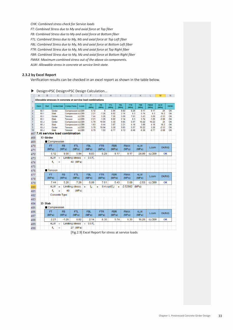
Comp./Tens.: Compression or Tension Stress Stage: Construction stage at which stresses are maximum at the corresponding section. CHK : Combined stress check for construction stages FT : Combined Stress due to My and axial force at Top fiber FB : Combined Stress due to My and axial force at Bottom fiber FTL : Combined Stress due to My, Mz and axial force at Top Left fiber FBL : Combined Stress due to My, Mz and axial force at Bottom Left fiber FTR : Combined Stress due to My, Mz and axial force at Top Right fiber FBR : Combined Stress due to My, Mz and axial force at Bottom Right fiber FMAX : Maximum combined stress out of the above six components. ALW : Allowable stress of cross section at construction stage. TTFc : Tensile resistance of concrete corresponding to the triangular block TTFs : Tensile resistance of tensile reinforcement

31 Chapter 1. Prestressed Concrete Girder Design
1.4.2 by Excel Report Verification results can be checked in an excel report.
Design>PSC Design>PSC Design Calculation>Check stress for cross section at a construcion stage…
[Fig.2.6] Excel Report for allowable stresses in concrete construction stage
2. Stress for cross section at service loads The element stress at service loads after losses shall meet the following conditions: The maximum compressive stress at service loads after losses ≤ allowable compressive stress of concrete: σc ≤ σca The maximum tensile stress at service loads after losses ≤ allowable tensile stress of concrete: σt
≤ σta
Load combinations that are defined as “Serviceability” in the Load Combination dialog (As shown in Fig.2.7) are verified as per their serviceability limit states.
Results>Load combinations>Concrete Design tab
[Fig.2.7] Load Combinations dialog
Active: Serviceability

32 Design Guide for midas Civil
2.1 Allowable stress of concrete (1) Allowable compressive stress of concrete
σca = 0.60 f’c (1.36)
(2) Allowable tensile stress of concrete midas Civil calculates the allowable tensile stress of concrete using the design code, as summarized in the table below.
[Table.1.5] Allowable stress of concrete at service load Construction
Type Case Allowable Stress To be checked
Segment & Joint No Reinforcement 0 Concrete Stress
Reinforcement fcr Concrete Stress
All else - fcr Concrete Stress
Refer to Section 2.1.1 for the classification of allowable stress.
2.2 Check stress for cross section at a service loads
cac , tat (1.42)
2.3 Check stress results for cross section at service loads
2.3.1 by Result Tables Results can be checked as shown in the table below.
Design>PSC Design>PSC Design Result Tables>Check stress for cross section at service loads…
[Fig.2.8] Result table for stress at a service loads
Elem: Element number Part: Check location (I-End, J-End) of each element
Comp./Tens.: Compression or Tension Stress LCom Name: Load Combination Name Type: Displays the set of member forces corresponding to moving load case
or settlement load case for which the maximum stresses are produced
CAN/CSA-S6-14 (8.8.4.6)
CAN/CSA-S6-14 (8.8.4.6)
33 Chapter 1. Prestressed Concrete Girder Design
CHK: Combined stress check for Service loads FT: Combined Stress due to My and axial force at Top fiber FB: Combined Stress due to My and axial force at Bottom fiber FTL: Combined Stress due to My, Mz and axial force at Top Left fiber FBL: Combined Stress due to My, Mz and axial force at Bottom Left fiber FTR: Combined Stress due to My, Mz and axial force at Top Right fiber FBR: Combined Stress due to My, Mz and axial force at Bottom Right fiber FMAX: Maximum combined stress out of the above six components. ALW: Allowable stress in concrete at service limit state.
2.3.2 by Excel Report Verification results can be checked in an excel report as shown in the table below.
Design>PSC Design>PSC Design Calculation…
[Fig.2.9] Excel Report for stress at service loads

34 Design Guide for midas Civil
3. Tensile stress for Prestressing tendons Compare the stress in tendon with the allowable stress for each tendon group. After immediate losses at anchorages, the maximum stress in tendon ≤ allowable stress. Elsewhere away from anchorages, the maximum stress in tendon ≤ allowable stress. After all losses, the maximum stress in tendon ≥ 0.45fpu
3.1 Allowable stress of tendon The Code presents the following stress limits for tendons depending on the tendon types:
[Fig.2.10] Allowable stress of tendon
Tendon Type can be specified in Fig1.8 Design parameter dialog. Pre/Post tensioning can be specified in Fig1.7 Tendon Property dialog. Midas Civil checks the following: Stress in tendon reflecting the initial losses at anchorages (FDL1) Stress in tendon immediately after anchor set elsewhere (FDL2) Stress in tendon at service limit state after all losses (FLL1) Allowable stresses corresponding to the described stresses above are set based on Fig.2.11 as follows.
(1) Allowable stress in tendon immediately after anchor set at anchorages (AFDL1) It is the maximum allowable stress in tendon at anchorages after immediate losses. The values for “At transfer > Pretensioning and Post-tensioning > At anchorages and couplers” in Fig.2.11. It is considered safe when FDL1 ≤ AFDL1.
(2) Allowable Stress in Tendon immediately after anchor set elsewhere (AFDL2) This is the maximum allowable stress immediately after anchor set elsewhere. The values for “At transfer > Post-tensioning > Elsewhere” in Fig.2.11. It is considered safe when FDL2 ≤ AFDL2.
(3) Allowable stress in tendon at service limit state after losses (AFLL1) This is the maximum allowable stress at service limit state after all losses. It is stated in the code that it should be at least 0.45fpu. It is considered safe when FLL1 ≥ AFLL1.
CAN/CSA-S6-14 (8.7.1)
CAN/CSA-S6-14 (8.7.1)

35 Chapter 1. Prestressed Concrete Girder Design
3.2 Check the stress in Prestressing tendons
3.2.1 Tendon Time-dependent Loss Graph Result>Bridge>Tendon Loss Graph
[Fig.2.11] Tendon Time-dependent Loss Graph
Stress in tendon can be checked with the Tendon Time-dependent Loss Graph.
3.2.2 by Result Tables
Verification results can be checked in an excel format as shown in the table below. Design>PSC Design>PSC Design Result Tables>Check tensile stress for Prestressing
tendons
[Fig.2.12] Result table for tensile stress for prestressing tendons
Tendon: Tendon profile name. For Post-tensioned: FDL1: Stress in tendon at anchorages.
The maximum stress in tendon at anchorages after immediate losses AFDL1: Allowable stress in tendon immediately after anchor set at anchorages. The allowable stress for FDL1 FDL2: Maximum stress in tendon along the length of the member away from anchorages, immediately
after anchor set. The maximum stress in tendon elsewhere along length of member away from anchorages
immediately after anchor set AFDL2: Allowable stress in tendon immediately after anchor set elsewhere.
The allowable stress for FDL2 FLL1: Maximum stress in tendon after all losses at the last stage.
The maximum stress in tendon at service limit state after all losses AFLL1: Allowable stress in tendon at service limit state after losses.
The allowable stress for FLL1(=0.45fpu) Elem : Element number for the Tendon
Part : Element location for the Tendon (I, 1/4, 1/2, 3/4, J) For Pre-tensioned: FDL1: Stress in tendon. FDL2: - FLL1: Maximum stress in tendon after all losses at the last stage. AFDL1: Allowable stress in tendon prior to transfer. AFDL2: - AFLL1: Allowable stress in tendon at service limit state after losses.
Elem : Element number for the Tendon Part : Element location for the Tendon (I, 1/4, 1/2, 3/4, J)

36 Design Guide for midas Civil
3.2.3 by Excel Report Verification results can be checked in an Excel report as shown in the table below.
Design>PSC Design>PSC Design Calculation> Check tensile stress for Prestressing
tendons…
[Fig.2.13] Excel Report for tensile stress for prestressing tendons
37 Chapter 1. Prestressed Concrete Girder Design
4. Principal stress at a construction stageFind the maximum principal tensile stress among the stress check points 1~10 of the cross-section at a construction stage and compare it to the allowable stress. In other words, maximum principal tensile stress ≤ allowable stress.
4.1 Allowable tensile stress
'0.110ta cif
(1.43)
Where f’ci is identical to that in Section 2.1.2.
4.2 Maximum principal stress The maximum principal tensile stress for each point at a constructions stage is computed as follows:
22 421
ptszxzxps
(1.44)
where
σx : Sum of axial stresses in ECS x-direction
σz : Sum of axial stresses in ECS z-direction
τs : Shear stress due to shear.
τt : Shear stress due to torsion.
τp : Shear stress due to shear reinforcement.
4.2.1 Beam stresses of PSC
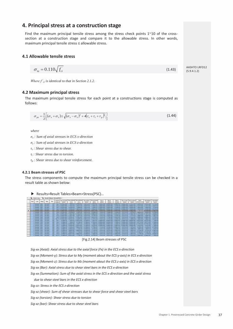
The stress components to compute the maximum principal tensile stress can be checked in a result table as shown below:
Results>Result Tables>Beam>Stress(PSC)…
[Fig.2.14] Beam stresses of PSC
Sig-xx (Axial): Axial stress due to the axial force (Fx) in the ECS x-direction
Sig-xx (Moment-y): Stress due to My (moment about the ECS y-axis) in ECS x-direction
Sig-xx (Moment-z): Stress due to Mz (moment about the ECS z-axis) in ECS x-direction
Sig-xx (Bar): Axial stress due to shear steel bars in the ECS x-direction
Sig-xx (Summation): Sum of the axial stress in the ECS x-direction and the axial stress
due to shear steel bars in the ECS x-direction
Sig-zz: Stress in the ECS z-direction
Sig-xz (shear): Sum of shear stresses due to shear force and shear steel bars
Sig-xz (torsion): Shear stress due to torsion
Sig-xz (bar): Shear stress due to shear steel bars
AASHTO LRFD12 (5.9.4.1.2)
38 Design Guide for midas Civil
Sig-Is (shear): Diagonal stress due to shear force
Sig-Is (shear+torsion): Diagonal stress due to torsion and shear force
Sig-Ps1: Maximum principal stress
Sig-Ps2: Minimum principal stress
4.3 Check principal stress at a construction stage
ps ta (1.45)
4.4 Check the principal stress results at a construction stage
4.4.1 by Result Tables Results can be checked as shown in the table below.
Design>PSC Design>PSC Design Result Tables>Principal stress at a construction stage …
[Fig.2.16] Result table for principal stress at a construction stage
Elem: Element number. Part: Check location (I-End, J-End) of each element. Comp./Tens.: Compression or Tension Stress. Stage: Construction stage. CHK: Principal stress check for construction stages. Sig_P1: Principal Stress at the left top of top flange. Sig_P2: Principal Stress at the right top of top flange. Sig_P3: Principal Stress at the right bottom of bottom flange. Sig_P4: Principal Stress at the left bottom of bottom flange. Sig_P5: Principal Stress at the top of left web.(at Z1 Level) Sig_P6: Principal Stress at the top of right web.(at Z1 Level) Sig_P7: Principal Stress at the neutral axis in left web.(at Z2 Level) Sig_P8: Principal Stress at the neutral axis in right web.(at Z2 Level) Sig_P9: Principal Stress at the bottom of left web.(at Z3 Level) Sig_P10: Principal Stress at the bottom of right web.(at Z3 Level) Sig_MAX: The maximum Principal stress among P1-P10. Sig_AP: Allowable principal stress at neutral axis in the web. When the user select Result Table, in case of composite section, all Principal Stress will be deactivated, and if the composite and noncomposite sections are modelled together, all principal stress will be activated. In case of noncomposite section, CHK and allowable stress(Sig_AP) will not be presented.
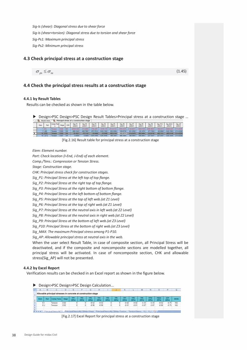
4.4.2 by Excel Report Verification results can be checked in an Excel report as shown in the figure below.
Design>PSC Design>PSC Design Calculation…
[Fig.2.17] Excel Report for principal stress at a construction stage

39 Chapter 1. Prestressed Concrete Girder Design
5. Principal stress at service loads(Excluding torsional shear stress)
Find the maximum principal tensile stress among the stress check points 1~10 of the cross-section at service loads and compare it to the allowable stress. In other words, maximum principal tensile stress ≤ allowable stress. Note that in this calculation, the shear effects due to torsion are excluded.
5.1 Allowable tensile stress The code does not present allowable stress values regarding the maximum principal tensile stress during construction stage. The program refers to AASHTO-LRFD12 for this particular case.
'0.110ta cf
(1.46)
5.2 Maximum principal stress The maximum principal tensile stress for each point at a construction stage is computed as follows:
22 4
21
ptszxzxps
(1.47)
where,
σx : Sum of axial stresses in ECS x-direction
σz : Sum of axial stresses in ECS z-direction
τs : Shear stress due to shear.
τt : Shear stress due to torsion.
τp : Shear stress due to shear reinforcement.
5.2.1 Beam stresses of PSC The stress components to compute the maximum principal tensile stress can be checked from a result table shown below: Refer to 2.4.2.1 Beam stresses of PSC.
5.3 Check principal stress at service loads
ps ta (1.48)
5.4 Check the principal stress results at service loads
5.4.1 by Result Tables Results can be checked as shown in the table below.
Design>PSC Design>PSC Design Result Tables> Result table for principal stress at service
loads(excluding torsional shear stress)…
[Fig.2.18] Result table for principal stress at service loads (excluding torsional shear stress)

40 Design Guide for midas Civil
Elem: Element number. Part: Check location (I-End, J-End) of each element. Comp./Tens.: Compression or Tension Stress. Stage: Construction stage. CHK: Principal stress check for construction stages. Sig_P1: Principal Stress at the left top of top flange. Sig_P2: Principal Stress at the right top of top flange. Sig_P3: Principal Stress at the right bottom of bottom flange. Sig_P4: Principal Stress at the left bottom of bottom flange. Sig_P5: Principal Stress at the top of left web.(at Z1 Level) Sig_P6: Principal Stress at the top of right web.(at Z1 Level) Sig_P7: Principal Stress at the neutral axis in left web.(at Z2 Level) Sig_P8: Principal Stress at the neutral axis in right web.(at Z2 Level) Sig_P9: Principal Stress at the bottom of left web.(at Z3 Level) Sig_P10: Principal Stress at the bottom of right web.(at Z3 Level) Sig_MAX: The maximum Principal stress among P1-P10. Sig_AP: Allowable principal stress at neutral axis in the web.
5.4.2 by Excel Report
Verification results can be checked in an excel report as shown in the table below.
Design>PSC Design>PSC Design Calculation…
[Fig.2.19] Excel Report for principal stress at service loads (excluding torsional shear stress)
6. Principal stress at service loads Find the maximum principal tensile stress among the stress check points 1~10 of the cross-section at service loads and compare it to the allowable stress. Here both shear and torsion will be reflected in the stress calculation. In other words, maximum principal tensile stress ≤ allowable stress.
6.1 Allowable tensile stress
'0.110ta cf (1.49)
6.2 Maximum principal stress The maximum principal tensile stress for each point at a construction stage is computed as follows:
22 4
21
ptszxzxps
(1.50)
where,
σx : Sum of axial stresses in ECS x-direction
σz : Sum of axial stresses in ECS z-direction
τs : Shear stress due to shear.
τt : Shear stress due to torsion.
τp : Shear stress due to shear reinforcement.

41 Chapter 1. Prestressed Concrete Girder Design
6.2.1 Beam stresses of PSC The stress components to compute the maximum principal tensile stress can be checked from a result table shown below: Refer to 2.4.2.1 Beam stresses of PSC.
6.3 Check principal stress at service loads
ps ta (1.51)
6.4 Check the principal stress results at service loads
6.4.1 by Result Tables Results can be checked as shown in the table below.
Design>PSC Design>PSC Design Result Tables>Principal stress at service loads…
[Fig.2.20] Result table for principal stress at service loads
Elem: Element number. Part: Check location (I-End, J-End) of each element. Comp./Tens.: Compression or Tension Stress. Stage: Construction stage. CHK: Principal stress check for construction stages. Sig_P1: Principal Stress at the left top of top flange. Sig_P2: Principal Stress at the right top of top flange. Sig_P3: Principal Stress at the right bottom of bottom flange. Sig_P4: Principal Stress at the left bottom of bottom flange. Sig_P5: Principal Stress at the top of left web.(at Z1 Level) Sig_P6: Principal Stress at the top of right web.(at Z1 Level) Sig_P7: Principal Stress at the neutral axis in left web.(at Z2 Level) Sig_P8: Principal Stress at the neutral axis in right web.(at Z2 Level) Sig_P9: Principal Stress at the bottom of left web.(at Z3 Level) Sig_P10: Principal Stress at the bottom of right web.(at Z3 Level) Sig_MAX: The maximum Principal stress among P1-P10. Sig_AP: Allowable principal stress at neutral axis in the web.
6.4.2 by Excel Report
Verification results can be checked in an excel report as shown in the table below.
Design>PSC Design>PSC Design Calculation…
[Fig.2.21] Excel Report for principal stress at service loads

42 Design Guide for midas Civil
7. Check crack Maximum crack width is compared with a calculated (expected) crack width for the crack limit state check. In other words, calculated crack width ≤ maximum crack width
7.1 Calculate crack widths
(1) Determine srm
50 0.25 brm c
c
ds k
(1.52)
where kc : 0.5 for bending db : Diameter of outer reinforcement(tendon) (bottom row)
sc
ct
AA for bending
As : the area of reinforcement contained within Act Act : the effective tension area of concrete cross-section in hc,ef.
, min 2.5 ,3c ef
h xh h d
(1.53)
[Fig.2.22] effective tension area of concrete cross-section
(2) Determine εsm
2
1s wsm
s s
f fE f
(1.54)
where fs : stress in reinforcement at the serviceability limit state on the basis of crack section
midas Civil uses the stress, at service loads, of reinforcement(or tendon) located at a greatest distance from the extreme compression fiber.
fw : stress in reinforcement under the conditions causing initial cracking on the basis of crack section
Stress of reinforcement at initial crack is calculated with the following steps. Strain of concrete is first calulcated based on the crack strength(fcr).
εc = Ec/fcr (1.55) εc is the strain of concrete at crack strengthas well as the strain of concrete at the extreme tension fiber.
CAN/CSA-S6-14 (8.12.3.2)

43 Chapter 1. Prestressed Concrete Girder Design
1) Using εc, the strain (εs) of the outer reinforcement is computed.
2) Stress of reinforcement is calculated based on its strain(εs).
fw = Es εs (1.56) 3) Determine w
b c rm smw k s (1.57)
Where
Kb : 1.2 for epoxy-coated reinforcing steel
1.0 for all other component
Coating condition of reinforcement can be entered in the PSC Design parameter dialog.
PSC> Design Parameter> Parameters…
[Fig.2.23] PSC Design parameter Dialog – Reinforcing Rebar
βc : 1.7 when cracking is caused by load
7.2 Maximum crack width, wmax
Wmax is determined depending on the type of exposure as shown in the table below.
[Fig.1.45] Maximum crack width, wmax
CAN/CSA-S6-14 (8.12.3.1)

44 Design Guide for midas Civil
Environmental Exposure (type of exposure) can be entered in the Design parameter dialog.
PSC> Design Parameter> Parameters…
[Fig.2.24] PSC Design parameter Dialog – Environmental Exposure
Wmax is determined depending on the type of exposure as shown in the table below.
[Table1.6 ]Coefficient k2
Type of Exposure wmax
(a) De-icing Chemical 0.15
(b) No deicing chemical 0.2
(c) Exposed to earth or fresh water 0.2 (d) Exposed to swamps maash, salt
water, or aggressive back fill
0.15
(e) Cast against and Permanently 0.2
(f) various 0.2
7.3 Check crack width results at service loads
7.3.1 by Result Tables Results can be checked as shown in the table below.
Design>PSC Design>PSC Design Result Tables>Check crack width at service loads…
[Fig.2.25]Result table for crack width at service loads
Elem: Element number Part: Check location (I-End, J-End) of each element Top/Bottom: At top of element, at bottom of element

45 Chapter 1. Prestressed Concrete Girder Design
LCom. Name: Load combination name. Type: produce maximum and minimum member force components for the load
combinations including moving load cases or settlement load cases. Check:OK/NG FT : Stress at the top (+ compression, - tension) FB : Stress at the bottom (+ compression, - tension) Wk : calculated crack width Wmax : Maximum crack width
7.3.2 by Excel Report Verification results can be checked in an excel report as shown in the table below.
Design>PSC Design>PSC Design Calculation…
[Fig.2.26]Excel Report for crack width at service loads

CAN/CSA S6 -14
Chapter 2.
Steel CompositeI - Girder Design

Steel Composite I-Girder DesignChapter 2.
Steel Composite I-Girder Bridge
Check Constructability
Check Shear Connector

Chapter 2. Steel Composite I-Girder Design : CAN/CSA S6-14
Introduction
Chapter2. Steel Composite I-Girder Design – CAN/CSA S6-14 49
1. CAN/CSA S6-14 Steel Composite I-Girder 1.1 Check List of CAN/CSA S6-14 Steel Composite I-Girder For CAN/CSA S6-14 Steel Composite Design, Limit State Design is applied. The criteria that Steel Composite I-Girder must follow for Limit State Design is as follows.
(1) Ultimate Limit State Review on bending strength, lateral torsional buckling and shear strength (2) Serviceability Limit State Review on permanent deformation (3) Constructibility Review on bending and shear occurring from load combinations during construction stages (4) Fatigue Limit State Review on fatigue in steel and concrete materials in Steel Composite girder
1.2 Classification of Steel Composite Steel Composite section can be categorized by the following classification groups.
(1) Section Shape Type There are three main section shape types in midas Civil; I, Box and Tub shapes. In the case ofbox and tub sections, there are two more cases, single or multiple box section.
I Box Tub
Figure 1.1 Section Shape Type (2) Moment Type : Positive / Negative For continuous beams, negative moments may occur around interior supports. Design codemay apply different formulas for these cases. (3) Bridge Type : Straight / Curved Based on the horizontal alignment of a bridge, it can be classified as either straight or curved. The program recognizes curved bridges based on the input of the girder radius for each element.

50 Design Guide for midas Civil
(4) Classification of Cross-sections: Class 1 / Class 2 / Class 3 / Class 4 Structural sections shall be designated as Class 1, 2, 3, or 4 depending on the width-to-thickness ratio of the elements that make up the cross-section and on the conditions ofloading.
Table 1.1 Steel Section Classification
Type Description
Class 1 A Class 1 section is one that will attain the plastic moment capacity, adjusted for the presence of axial force if necessary, and permit subsequent redistribution of bending moment.
Class 2 A Class 2 section is one that will attain the plastic moment capacity, adjusted for the presence of axial force if necessary, but not necessarily permit subsequent moment redistribution.
Class 3 A Class 3 section is one that will attain the yield moment capacity, adjusted for the presence of axial force if necessary.
Class 4 A Class 4 section is one in which the slenderness of the elements making up the cross-section exceeds the limits of Class 3.
1.3 Stiffeners of Steel Composite The program considers transverse and longitudinal stiffeners.
Table 1.2 Types of Stiffeners
Type Description
Transverse Stiffeners
Transverse stiffeners are usually provided to increase shear resistance by tension field action. These work as anchors for the tension so that post buckling shear resistance can be developed. It should be noted that elastic web shear buckling cannot be prevented by transverse stiffeners.
Longitudinal Stiffeners
Longitudinal stiffeners may be provided to increase flexural resistance by preventing local buckling. These work as restraining boundaries for compression elements so that inelastic flexural buckling stress can be developed in a web. It consists of either a plate welded longitudinally to one side of the web, or a bolted angle.
Figure 1.2 Longitudinal Stiffener and Transverse Stiffener
CAN/CSA S6-14 10.9.2.1

51Chapter 2. Steel Composite I-Girder Design - CAN/CSA S6-14
2. Considerations of Steel Composite Design 2.1 Construction Stage for steel composite During the construction of a steel composite bridge, the steel girder is constructed before theconstruction of the concrete deck of the upper part of the structure. The steel composite sectionis divided into three major steps.
Table 1.3 Construction Stage for Steel Composite Section
Construction stage for steel composite section
Description
Only Steel Girder (non-composite)
Only the steel girder has been constructed.
Steel girder and concrete deck
as load (non-composite)
Although the concrete deck has been constructed, it has not hardened yet. Therefore, the weight of the wet concrete is applied to the steel girder as a load condition.
Steel girder and concrete deck
as member (composite)
After concrete is hardened, the strength and stiffness are formed. Hereafter, the steel girder and concrete deck work as a complete composite section.
2.2 Time Dependent Material ▪ Steel composite section is composed of steel and concrete. Concrete is a time dependentmaterial and transforms due to creep and shrinkage. Also, the restraints imposed by the shearconnectors cause additional stresses within the composite section. Therefore, time dependentcharacteristics (creep and shrinkage) must be taken into consideration. ▪ Modular ratio is the ratio of modulus of elasticity of steel to that of concrete. The short-termmodular ratio "n" is used for transient loads in the program. Long-term modular ratio "3n" is usedfor permanent loads acting after composite action.
3. Calculation of Plastic Moment and Yield Moment 3.1 Section Classification
The steel section is classified in accordance with Clause 10.9.2. The classification is carriedout separately for positive and negative bending for both composite and non-compositesections. The classification of a cross-section depends on the width to thickness ratio of theparts subject to compression. A cross-section is classified according to the highest (leastfavorable) class of its compression parts. For calculating the limiting width-to-thickness ratios of the web of monosymmetric steelsections, h is replaced by 2dc. However, for the classification of composite section, the h is
CAN/CSA S6-14 10.9.2.1 CAN/CSA S6-14 10.10.2.1

52 Design Guide for midas Civil
used for the web. The resistance of the top flange of the composite section under positive moment is assumedas not being limited by its local buckling resistance since it is restrained by effective attachment to a concrete flange by shear connectors. The top flange is always classified asClass 1.
3.2 Plastic Moment (Mp) of Composite Section in Positive Flexure
If the positive moment is applied on a class 1 or class 2 section, MP is calculated as shown inTable 1.4.
Figure 1.3 Case of calculation of Mp in positive moment
Table 1.4 Calculation of and Mp for section in Positive Flexure
Case PNA Condition and pM
In Web wt PP
rtrbsc PPPP
]1[2 w
rbrtsct
PPPPPPD
Y
])([2
22YtY
DP
M w
][ ttwwrbrbrtrtss dPdPdPdPdP
In Top flange
cwt PPP
rtrbs PPP
])([2
22YtY
tP
Mc
c
][ ttwwrbrbrtrtss dPdPdPdPdP
Concrete Deck, Below Prb
cwt PPP
rtrbss
rb PPPtc
s
s
tPY
M2
2
][ ttwwccrbrbrtrt dPdPdPdPdP
Concrete Deck, at Prb
rbcwt PPPP
rtss
rb PPtc
rbCY
s
s
tPY
M2
2
][ ttwwccrtrt dPdPdPdP

53Chapter 2. Steel Composite I-Girder Design - CAN/CSA S6-14
Concrete Deck, Above Prb Below Prt
rbcwt PPPP
rtss
rt PPtc
s
rbrttwcs P
PPPPPtY )(
s
s
tPY
M2
2
][ ttwwccrbrbrtrt dPdPdPdPdP
Concrete Deck, at Prt
rtrbcwt PPPPP
ss
rt Ptc
rtCY
s
s
tPY
M2
2
][ ttwwccrbrb dPdPdPdP
Concrete Deck, Above Prt
rtrbcwt PPPPP
ss
rt Ptc
s
rttwcrbs P
PPPPPtY )(
s
s
tPY
M2
2
][ ttwwccrbrbrtrt dPdPdPdPdP
Where, : Distance from the plastic neutral axis to the centerline of the top layer of longitudinal concrete
deck. : Distance from the plastic neutral axis to the centerline of the bottom layer of longitudinal
concrete deck. : Distance from the plastic neutral axis to the midthickness of the tension flange. : Distance from the plastic neutral axis to middepth of the web. : Distance from the plastic neutral axis to midthickness of the compression flange. : Distance from the plastic neutral axis to midthickness of the concrete deck.
(by reinforcement) (by reinforcement)
(by steel girder)
(by steel girder) (by steel girder)
(by concrete slab)
3.3 Plastic Moment (Mp) of Composite Section in Negative Flexure Under negative moment, Mp is calculated by either of the two following methods. Please refer to Table 1.5 for the equations.
Figure 1.4 Case of calculation of Mp in Negative Moment

54 Design Guide for midas Civil
Table 1.5 Calculation of and Mp for section in Negative Flexure
Case PNA Condition and pM
In Web rtrbtwc PPPPP
In Top flange rtrbtwc PPPPP
Where,
(by reinforcement) (by reinforcement)
(by steel girder) (by steel girder)
(by steel girder)

Chapter 2. Steel Composite I-Girder Design : CAN/CSA S6-14
Modeling and Design Variables
Chapter2. Steel Composite I-Girder Design – CAN/CSA S6-14 55
1. Modeling Design Variables In this chapter, the design variable values, the meaning behind the design requirements, and the design process for Steel Composite Design in midas Civil are explained.
1.1. Composite Section Data The steel composite section is mainly composed of steel girder and concrete slab. Stiffeners can be added to steel girder section while longitudinal reinforcement can be added to reinforce concrete slab. In this section, the input methods for these sections and the meaning and application of design variables are explained.
1.1.1 Composite Section (1) Composite Section Data
Properties > Section > Section Properties> Add > Composite Tab
Figure 1.5 Section Data Dialog Box
1.1.1 Composite Section (1) Composite Section Data
1) The value of Bc for the slab is used as the effective width of the concrete deck. 2) Multiple Modulus of Elasticity Option To design the steel composite section, the modulus of elasticity for short-term and long-term effect in creep and shrinkage can be input. The modulus of elasticity input here is applied for construction stage analysis of Steel Composite section as shown in Figure 1.6.
Figure 1.6 Elastic Modulus ratio for Construction Stage

56 Design Guide for midas Civil
(2) Section Stiffener
Properties > Section > Section Properties> Add > Composite Tab > Stiffeners Button...
Figure 1.7 Section Stiffener Dialog Box
1.1.2 Longitudinal Reinforcement
Design > Composite Design > Longitudinal
Reinforcement ...
Figure 1.8 Longitudinal Reinforcement Dialog Box
(2) Section Stiffener (Longitudinal)
1) Types of longitudinal stiffeners that are useable are Flat, Tee, and U-Rib. 2) For I sections, stiffeners can be added on either side of the web. For Box/Tub sections, upper and lower flanges can be installed as well as the web panel. 3) When the check box under c column is checked on, the stiffness value of the stiffener is considered in analysis. Otherwise, the value is not considered for analysis. Regardless of whether or not the check box is checked on or off, longitudinal stiffeners are considered in design. It is also required for classifying the interior panels in shear check as stiffened/unstiffened.
1.1.2 Longitudinal Reinforcement
In a steel composite section, the longitudinal reinforcements are arranged within the concrete deck. The moment resistance is calculated as shown in Table 1.6.
Table 1.6 Applicability of concrete and reinforcement for the calculation of moment resistance
Case Positive Bending
Negative Bending
Figure
Concrete Slab Applied None
Rebar Applied Applied
57Chapter 2. Steel Composite I-Girder Design - CAN/CSA S6-14
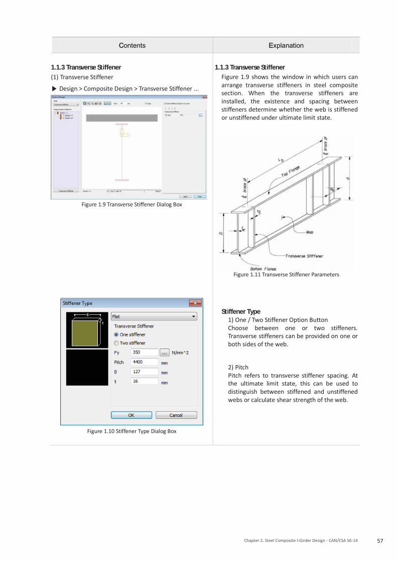
1.1.3 Transverse Stiffener (1) Transverse Stiffener
Design > Composite Design > Transverse Stiffener ...
Figure 1.9 Transverse Stiffener Dialog Box
Figure 1.10 Stiffener Type Dialog Box
1.1.3 Transverse Stiffener
Figure 1.9 shows the window in which users can arrange transverse stiffeners in steel composite section. When the transverse stiffeners are installed, the existence and spacing between stiffeners determine whether the web is stiffened or unstiffened under ultimate limit state.
Figure 1.11 Transverse Stiffener Parameters
Stiffener Type 1) One / Two Stiffener Option Button Choose between one or two stiffeners. Transverse stiffeners can be provided on one or both sides of the web.
2) Pitch Pitch refers to transverse stiffener spacing. At the ultimate limit state, this can be used to distinguish between stiffened and unstiffened webs or calculate shear strength of the web.

58 Design Guide for midas Civil
1.2. Design Material Data For the design of steel composite section, construction stage and time dependent material properties of concrete can be applied. In this section, the input method for the time dependent properties of concrete and material data for steel composite section is explained.
Contents Explanation
1.2.1 Time Dependent Material (1) Creep/Shrinkage
Properties > Time Dependent Material > Creep/Shrinkage ...
Figure 1.12 Add/Modify Time Dependent Material Dialog Box
(Creep/Shrinkage)
(2) Comp. Strength
Properties > Time Dependent Material > Comp. Strength ...
Figure 1.13 Add/Modify Time Dependent Material Dialog Box
(Compression Strength)
1.2.1 Time Dependent Material (1) Creep/Shrinkage The time dependent properties of concrete, such as creep and shrinkage, are defined. During construction stage analysis of bridges, these properties are utilized for concrete material.
(2) Comp. Strength
In order to reflect the change in the modulus of elasticity of concrete, the change in compressive strength or modulus of elasticity is defined. Aging effects may vary for each construction stage since concrete is poured at different locations.

59Chapter 2. Steel Composite I-Girder Design - CAN/CSA S6-14
Contents Explanation
1.2.2 Modify Composite Material (1) Modify Composite Material
Design > Composite Design > Design Material ...
Figure 1.14 Modify Composite Material Dialog Box
1.2.2 Modify Composite Material The materials utilized for steel composite sections are provided in the SRC material properties. The materials should be defined as SRC Type.
(1) Modify Composite Material Figure 1.14 shows the dialog box where users can type in material characteristics for the steel composite section design. The material property values entered will have a priority over the values entered in the Material Data dialog box.
1) Steel Material Selection Define modulus of elasticity, yield strength and tensile strength of steel for design purpose. In the current version, different yield strengths for different thicknesses of steel are not supported.
2) Concrete Material Selection Define compressive strength of concrete slab for design purpose.
3) Reinforcement Selection Define yield strength of reinforcement in the slab.

60 Design Guide for midas Civil
1.3. Design Parameters for Composite Section
Contents Explanation
1.3.1 Design Parameter
Design > Composite Design > Design Parameters ...
Figure 1.15 Composite Steel Girder Design Parameter Dialog Box
1.3.2 Unbraced Length
Design > Composite Design > Unbraced Length ...
Figure 1.16 Unbraced Length Dialog Box
1.3.1 Design Parameter
(1) Strength Resistance Factor Strength Resistance Factor is defined.
By clicking , the resistance factors are automatically set to the default values defined in CAN/CSA S6-14. The values can also be modified or entered manually.
(2) Girder Type for Box/Tub Section If Single Box Section is selected, the following clauses are applied for the box/ tub girder design. 10.12.8.4 Moment resistances 10.12.8.5 Combined shear and torsion
(3) Options For Construction Stage
If this option is checked, ULS check for steel section only during construction is performed.
(4) Design Parameters Design and result outputs are generated for the limit states checked in the Design Parameters.
1.3.2 Unbraced Length Unbraced length for steel composite section is considered. The value input here has higher priority than the value calculated from Span Group.
(1) Lb Laterally Unbraced Length is used to calculate lateral torsional buckling resistance in compression flange of I Girder or top flange of Tub Girder. Laterally Unbraced Length is automatically determined using ‘Span Information’ and by assigning member type of cross-frames as ‘Brace’ using the Common Parameter > Modify Member Type function. The user can define/modify the laterally unbraced lengths.

61Chapter 2. Steel Composite I-Girder Design - CAN/CSA S6-14
Contents Explanation
1.3.3 Shear Connectors
Design > Composite Design > Shear Connectors ...
Figure 1.17 Shear Connector Dialog Box
1.3.3 Shear Connectors In this program, studs are used for shear connectors. The parameters used for calculation are shown below.
(1) Category Category for fatigue check, it is fixed as D. (2) Fu Minimum tensile strength of the stud steel (3) Shear Connector Parameters
Figure 1.18 Shear Connector Parameters
(4) Length Between Maximum Moment and Zero Moment The Length between Maximum Moment and Zero Moment needs to be inputted by users to verify pitch as per ultimate limit state.

62 Design Guide for midas Civil
Contents Explanation
1.3.4 Fatigue Parameter
Design > Composite Design > Fatigue Parameter ...
Figure 1.19 Fatigue Parameters Dialog Box
1.3.5 Span Information
Structure > Wizard > Composite Bridge > Span Information ...
Figure 1.20 Span Information Dialog Box
1.3.4 Fatigue Parameter (1) Weight of Truck(W)
Load level in CL-W, kN (2) Design Life(y)
Design life, years (3) Number of Stress Cycles(Nd) Number of design stress cycles experienced for each passage of the design truck (4) Reduction Factor(ρ) (5) Average Daily Truck Traffic
1.3.5 Span Information The elements of composite sections are defined as one Span Group. The Span Group will serve the following functions.
- Calculation of Unbraced Length When assigning a span group, support properties are considered for calculating the unbraced length. The unbraced length can also be manually inputted once the corresponding support conditions under the support column are selected. Using the span parameters inputted, the unbraced length can be calculated automatically. However, if the unbraced length is inputted in Section 1.3.2, this value will be applied as the unbraced length first.

63Chapter 2. Steel Composite I-Girder Design - CAN/CSA S6-14
Contents Explanation
1.3.6 Curved Bridge Information
Design > Composite Design > Curved Bridge Info ...
Figure 1.21 Curved Bridge Information Dialog Box
1.3.7 Design Force/Moment
Design > Composite Design > Design Tables > Design Force/Moment...
Figure 1.22 Design Force/Moment Dialog Box
1.3.6 Curved Bridge Information Once the girder radius value of the element units in the steel composite section is entered, the corresponding elements are categorized as curved bridges.
(1) Radius is used to determine the factored bending moment in the flange due to torsional warping. (2) In the current version, the curve type of convex or concave is not used.
1.3.7 Design Force/Moment This feature displays design member forces (strong axis moment, My), weak-axis moment (Mz) and shear stress (VU) for the local axis of elements under selected load combination of steel composite section.

64 Design Guide for midas Civil
1.4 Load Combination for steel composite section 1.4.1 Application of load combination in midas Civil for CAN/CSA S6-14
(1) Application of load combinations and factors in midas Civil for CAN/CSA S6-14 The load combinations used for the review of each limit state are shown below.
Figure 1.23 Load factors and load combinations
Using the Auto Generation feature of the program, the load combinations regulated by the design code can be automatically generated. Load factors are considered for each load combinations in this program.
Figure 1.24 Live load factors ultimate limit states
Figure 1.25 Permanent loads — Maximum and minimum values of load factors for ULS

65Chapter 2. Steel Composite I-Girder Design - CAN/CSA S6-14
(1) Auto Generation of Load Combinations
Result > Combination > Load Combination > Composite Steel Girder Design > Auto Generation ...
Figure 1.26 Automatic Generation of Load Combinations
Dialog Box
(1) Auto Generation of Load Combinations This feature automatically generates load combinations under provision of CAN/CSA S6-14.
1) Design Code When load combinations are generated, they strictly follow the design code selected by the user. 2) Load Factors for Permanent Loads (αD, αE, αP) The user can generate load combinations using maximum value or minimum value or both. When associated load type does not exist, these factors are not activated.

66 Design Guide for midas Civil
1.4.2 Load combination type for steel composite design Load combination type must be assigned before performing design. When load combinations are generated by auto-generation, the load combination type is automatically assigned, but when load combinations are defined manually or modified, the load combination type should be assigned by the user. Load combinations used in the steel composite section design are categorized under Load Combination Type.
Contents Explanation
(1) Load Combination Type
Design > Composite Design > Load Combination Type...
Figure 1.27 Load Combination Type Dialog Box
(1) Load Combination Type 1) Ultimate Limit State Choose load combinations for use under review of ultimate limit state. 2) Service Limit State Choose load combinations for review of serviceability limit state. 3) Fatigue Limit State Choose load combinations for review in fatigue limit state.
1.5 Modeling Steel Composite Sections for Construction Stage Analysis In this section, methods of construction stage modeling, implementation of time-dependent material properties of concrete in steel composite section and 3 types of design member forces applied to steel composite section design are explained. Construction stages of steel composite section can be implemented differently for case 1 to 3 as in Table 1.7.
Table 1.7 Modeling Construction Stage Cases for Steel Composite Design
Case Construction Stage Time Dependent Material(Creep / Shrinkage)
Case 1 Defined
Defined
Case 2 Not Defined (Apply modular ratio of 3n)
Case 3 Not Defined Not Defined (Apply modular ratio of 3n)
1.5.1 Member forces and stresses used in steel composite section design
(1) Member forces For design of steel composite section, member forces per construction stage of steel composite section must be calculated. The program considers two main factors for design and review of construction stage of steel composite section. ▪Construction stages of steel composite section ▪Time dependent material properties of Concrete (Creep, Shrinkage and Compressive Strength)

67Chapter 2. Steel Composite I-Girder Design - CAN/CSA S6-14
Design member forces used for design of steel composite section are divided into three main categories. Table 1.8 Design Force and Moment for Steel Composite Design
Design Force/Moment Description
Dead (Before) Member forces due to permanent loads occurring before the concrete deck is activated. Only steel section properties are used to calculate stresses. ex) Self weight of steel and concrete deck
Dead (After) Member forces due to permanent loads occurring after concrete deck is activated Long term section properties of composite section are used. ex) Self weight of wearing surface and barrier
Short Term Member forces from the post-construction state and load cases not included in the above categories. Short term section properties of composite section are used. ex) Traffic loads, wind loads
When construction stages are included in the model in midas Civil, the design moments for Dead (Before) are taken as the moments of steel section due to Dead Load (CS) and Erection Load (CS) whose load type is Dead Load (D) and the design moments for Dead (After) are taken as the moments of composite section due to Erection Load (CS) whose load type is Dead Load of Component and Attachments (DC) or Dead Load of Wearing Surfaces and Utilities (DW). Example:
Permanent Loads Load Type Analysis results
Load Factor
Design forces Stage 1
Steel only Stage 2
Composite Dead
(Before) Dead
(After) Self Weight of Steel Dead Load (CS) 100 100 1.1 110
Self Weight of Concrete Erection (D) 100 100 1.2 120 Self Weight of Barrier Erection (DC) 0 100 1.2 120
Self Weight of Wearing Surface
Erection (DW) 0 100 1.5 150
Sum 230 270
Above rule has changed in Civil 2018 (v1.2) in order to account for various erection sequence of slab. The design moments for Dead (Before) and Dead (After) are determined as shown in the table below.
Dead Load (CS) Erection Load (CS) Moments applied to steel section Dead (Before) Dead (Before) Moments applied to composite section Ignored Dead (After)
(2) Stress Bending stress used for design of steel composite section is calculated as follows:
Where,
Md : bending moment at SLS due to dead load, steel section only
Msd : bending moment at SLS due to superimposed dead load, composite section
ML : bending moment at SLS due to live load, composite section
S : elastic section modulus of steel section
S3n : elastic modulus of section comprising the steel beam and the concrete slab, calculated using a modular ratio of 3n, long-term load, positive moment

68 Design Guide for midas Civil
Sn : elastic modulus of section comprising the steel beam and the concrete slab, calculated using a modular ratio of n, short-term load, positive moment
S’ : elastic modulus of composite section comprising the steel section and reinforcement, negative moment 1.5.2 Case 1 In Case 1, construction stages and time dependent material properties of concrete (Creep/Shrinkage) are defined and Multiple Modulus of Elasticity is not checked on in the Section Data dialog. The effects of creep and shrinkage of concrete are directly calculated and checked by Creep Secondary (CS) or Shrinkage Secondary (CS) load cases. The Composite sections for Construction Stage function must be defined. Otherwise, the sections shall be excluded from design. Note that if time dependent material property information is inputted as well as long-term modulus of elasticity, long-term modulus of elasticity has higher priority in consideration of calculation.
Define Composite Section for Construction Stage
Contents Explanation
Composite Section for Construction Stage
Load >Load Type> Construction Stage > Composite Section for C.S...
Figure 1.28 Add/Modify Composite Section for Construction Stage Dialog
Composite Section for Construction Stage For definition of composite section for construction stage, information in this window must be defined. (1) Active Stage Construction stage where steel composite section should be activated is inserted. (2) Construction sequence
1) "Material Type" column □ By choosing Element, material property of the element is used. □ By selecting Material, material information chosen under "Material" Column is applied with higher priority. 2) Composite Stage column Construction stages where steel girder and concrete slab should be activated are chosen separately. 3) Age column Age information when each part is activated is input. Information in this column has higher priority over the age input during definition of construction stage.

69Chapter 2. Steel Composite I-Girder Design - CAN/CSA S6-14
Define Erection Load
(1) Define Erection Load
Analysis > Analysis Control > Construction Stage > Load Cases to be Distinguished from Dead Load for C.S Output >Add (Modify/delete)...
Figure 1.29 Define Erection Load Dialog
1) Define Erection Load Erection Load is defined.
1) Load Type for C.S Determine the Load Type for the construction stages of the composite section. Load types are considered by the software for auto generation of load combinations. 2) Assignment Load Cases Define Erection Load by selecting and moving the Load Cases desired from the List of Load Case panel to the Selected Load Case panel.
1.5.3 Case 2 In Case 2, construction stages are defined without the time dependent material property (Creep/Shrinkage) information. Long term effects are considered using the long term modular ratio entered in the Section Data dialog box. Sections for different construction stages must be defined and differentiated using the Composite Section for Construction Stage definition. Otherwise, they will not be considered for the design check.
(1) Member forces under Dead (Before) Dead (Before) is applied before the concrete deck is activated. (Refer to Table 1.8 in the "Introduction") Self weight of steel and concrete belongs to Dead (Before).
(2) Member forces under Dead (After) The effects of Creep/Shrinkage are reflected by applying the ratio of elastic modulus that is inputted in the Section Data (Refer to Section 1.1.1 (1)) for the long-term stage. In other words, the Creep/Shrinkage effects are reflected by using the section information with the ratio of elastic modulus that considers the time dependent material property for the analysis and design. These long term modular ratios defined for considering creep and shrinkage, automatically generate Section Stiffness Scale Factors for the sections in which these are inputted. Section Stiffness Scale Factors need to be activated in the construction stages in accordance with the Composite Section for Construction Stage definition, i.e. the Section Stiffness Scale Factors are activated when the corresponding section becomes composite as per the definition of composite section for CS. Super-imposed dead loads, i.e. wearing surface, barrier belong to Dead (After).
(3) Short term member forces The ratio of elastic modulus of the composite section is calculated using the DB value inputted. All the load cases which are not activated in the Construction Stage are considered as the short-term loads.

70 Design Guide for midas Civil
1.5.4 Case 3 In case the construction stages are not defined, users can model and define steel composite sections by using the Load Case for Pre-Composite Section function.
Load > Load Type > Settlement/Misc. > Misc. > Pre-composite Section. For this case, short- and long-term ratios of elastic modulus defined in the section data (Refer to Section 1.1.1 (1)) are used. In this case, instead of member forces per construction stages, member forces under Dead (Before) is used to check the constructibility of the model.
(1) Member force under Dead (Before) In the Load Cases for Pre-Composite Section dialog box, users can define which load cases to account for the member forces and apply as Dead (Before) in design. Since this is for pre-composite state, the steel only section properties are used (Refer to Section 1.1.1 (1)).
Figure 1.30 Load Cases for Pre-Composite Section
(2) Member forces under Dead (After) Member forces under Dead (After) use the long term section properties. These loads should be separated from the short term member forces by the use of Analysis > Analysis Control > Boundary Change Assignment.
1) Data Selection Check the box corresponding to Section Stiffness Scale Factor. As explained earlier, Section Stiffness Scale Factors are used for considering the long term section properties.
2) Boundary Group Combination Create a boundary group combination considering the appropriate boundary groups from the boundary group list. The created boundary group combinations need to be selected for the post composite long term load cases. For the static load cases assigned with the section stiffness scale factor boundary groups, long term section property will be used.
Dead Load (Before)

71Chapter 2. Steel Composite I-Girder Design - CAN/CSA S6-14
Figure 1.31 Load Cases for Post-Composite Section
(3) Short-term member forces The ratio of elastic modulus from the database is used for the short-term loads of the composite section. All load cases are considered for the short-term loads except the ones considered for the Dead (Before) and Dead (After).
Dead Load (After)

Chapter 2. Steel Composite I-Girder Design : CAN/CSA S6-14
Application of CAN/CSA S6-14
72Chapter 2. Steel Composite I-Girder Design – CAN/CSA S6-14
1. Composite I Girder 1.1. ULS
1.1.1 Bending (1) Positive Moment - Class 1 & 2 sections Width-to-thickness ratio of elements in compression
Top Flange The flange is assumed to be restrained by concrete slab. Thus, it is considered as Class 1.
Web
Stress distribution Fully plastic stress distribution as shown in Figure 1.32.
CAN/CSA S6-14 10.11.5.1 10.9.2
CAN/CSA S6-14 10.11.5.2.1

73 Chapter 2. Steel Composite I-Girder Design – CAN/CSA S6-14
Figure 1.32 Class 1 and 2 sections in positive moment regions
Factored moment resistance, Mr Mr is calculated as shown in Table 1.9.
Figure 1.33 Case of calculation of Mp in positive moment
Table 1.9 Calculation of and Mp for section in Positive Flexure
Case PNA Condition and pM
In Web wt PP
rtrbsc PPPP
]1[2 w
rbrtsct
PPPPPPD
Y
])([2
22YtY
DP
M w
][ ttwwrbrbrtrtss dPdPdPdPdP
In Top flange
cwt PPP
rtrbs PPP
])([2
22YtY
tP
Mc
c
][ ttwwrbrbrtrtss dPdPdPdPdP
Concrete Deck, Below Prb
cwt PPP
rtrbss
rb PPPtc
s
s
tPY
M2
2
][ ttwwccrbrbrtrt dPdPdPdPdP

74 Design Guide for midas Civil
Concrete Deck, at Prb
rbcwt PPPP
rtss
rb PPtc
rbCY
s
s
tPY
M2
2
][ ttwwccrtrt dPdPdPdP
Concrete Deck, Above Prb Below Prt
rbcwt PPPP
rtss
rt PPtc
s
rbrttwcs P
PPPPPtY )(
s
s
tPY
M2
2
][ ttwwccrbrbrtrt dPdPdPdPdP
Concrete Deck, at Prt
rtrbcwt PPPPP
ss
rt Ptc
rtCY
s
s
tPY
M2
2
][ ttwwccrbrb dPdPdPdP
Concrete Deck, Above Prt
rtrbcwt PPPPP
ss
rt Ptc
s
rttwcrbs P
PPPPPtY )(
s
s
tPY
M2
2
][ ttwwccrbrbrtrt dPdPdPdPdP
Where, : Distance from the plastic neutral axis to the centerline of the top layer of longitudinal concrete
deck. : Distance from the plastic neutral axis to the centerline of the bottom layer of longitudinal concrete
deck. : Distance from the plastic neutral axis to the midthickness of the tension flange. : Distance from the plastic neutral axis to middepth of the web. : Distance from the plastic neutral axis to midthickness of the compression flange. : Distance from the plastic neutral axis to midthickness of the concrete deck.
(by reinforcement) (by reinforcement)
(by steel girder)
(by steel girder) (by steel girder)
(by concrete slab)
- Class 3 sections Width-to-thickness ratio of elements in compression
Top Flange The flange is assumed to be restrained by concrete slab. Thus, it is considered as Class 1.
Web
CAN/CSA S6-14 10.11.6.1
10.9.2

75 Chapter 2. Steel Composite I-Girder Design – CAN/CSA S6-14
Factored moment resistance, Mr For composite sections in which the depth of the compression portion of the web of the steel section, calculated on the basis of a fully plastic stress distribution, equals or is less than
, the factored moment resistance is determined in the same way as Class 1 & 2 under positive moment. When the depth of the compression portion of the web of the steel section, calculated on the basis of a fully plastic stress distribution, exceeds , the factored moment resistance, Mr, of the composite section is calculated on the basis of fully plastic stress blocks, as shown in Figure 1.34, as follows:
The area of the steel section in compression, A‘sc , includes the top flange and a web area of
, and the area of the steel section in tension, A‘st , is calculated as follows:
Figure 1.34 Class 3 Sections in positive moment regions
- Class 4 sections This section is not valid. Therefore, the moment resistance check is skipped. -Stiffened plate girders Width-to-thickness ratio of elements in compression
Top Flange The flange is assumed to be restrained by concrete slab. Thus, it is considered as Class 1.
Web The width-to-thickness ratio of a transversely stiffened web, h/w without longitudinal stiffeners, shall not exceed . If this requirement is not satisfied, the section is not valid. Therefore, the moment resistance check is skipped. The following provision of CAN/CSA S6-14 is not supported in the program. “In determining a width-to-thickness ratio, Fy may be replaced by the maximum compressive stress due to the factored ULS loads if the maximum shear at the FLS does not exceed Vr calculated in accordance with Clause 10.10.5.1, taking Ft = 0 and φs = 1.0.” When a longitudinal stiffener is provided, the width-to-thickness ratio, h/w, shall not exceed . If this requirement is not satisfied, the section is not valid. Therefore, the moment resistance check is skipped.
CAN/CSA S6-14 10.11.6.2.1
10.11.5.2
CAN/CSA S6-14 10.11.6.2.2
CAN/CSA S6-14 10.11.7.1
10.10.4.1 10.10.4.2

76 Design Guide for midas Civil
Factored moment resistance, Mr For composite sections in which the depth of the compression portion of the web of the steel section, calculated on the basis of a fully plastic stress distribution, does not exceed
, the factored moment resistance is determined in the same way as Class 1 & 2 under positive moment. When the depth of the compression portion of the web of the steel section, calculated on the basis of a fully plastic stress distribution, exceeds , whether or not longitudinal stiffeners are provided, the factored moment resistance, Mr, of the composite section is calculated in the same way as Class 3 under positive moment. (2) Negative Moment - Class 1 & 2 sections Width-to-thickness ratio of elements in compression
Bottom Flange
Web
Factored moment resistance, Mr When it is braced against lateral torsional buckling, Mr is calculated on the basis of a fully plastic stress distribution in the structural steel and reinforcement, as shown in Table 1.10.
Figure 1.35 Case of calculation of Mp in Negative Moment
Table 1.10 Calculation of and Mp for section in Negative Flexure
Case PNA Condition and pM
In Web rtrbtwc PPPPP
In Top flange rtrbtwc PPPPP
CAN/CSA S6-14 10.11.7.2.1
10.11.5.2
CAN/CSA S6-14 10.11.7.2.2
10.11.6.2.2
CAN/CSA S6-14 10.11.5.1
10.9.2

77 Chapter 2. Steel Composite I-Girder Design – CAN/CSA S6-14
Where,
(by reinforcement)
(by reinforcement) (by steel girder) (by steel girder)
(by steel girder)
For laterally unbraced members, Mr is based on its lateral torsional buckling resistance. The unbraced bending resistance of the structural steel section alone is used. For a section subjected to bending about its major axis and laterally unbraced over a length, L, the factored moment resistance, Mr, is calculated as
The critical elastic moment, Mu, of a monosymmetric section is taken as
where
where
Mmax = maximum absolute value of factored bending moment in unbraced segment, Nmm
Ma = factored bending moment at one-quarter point of unbraced segment, N mm
Mb = factored bending moment at midpoint of unbraced segment, N mm
Mc = factored bending moment at three-quarter point of unbraced segment, N mm L = length of unbraced segment of beam, mm
where βx= coefficient of monosymmetry
For doubly symmetric sections,
βx= 0.0 B1 = 0.0
so that
The general expression for the critical elastic moment and formulas for β x, J, and Cw for I-girder as specified in Clause C10.10.2.3 of CSA S6.1 are used.
CAN/CSA S6-14 10.11.5.3.1 10.10.2.3
CAN/CSA S6.1-14 10.10.2.3

78 Design Guide for midas Civil
where Iyc : minor axis moment of inertia of the compression flange only Iy : minor axis moment of inertia of the cross-section Ix : major axis moment of inertia of the cross-section
- Class 3 sections Width-to-thickness ratio of elements in compression
Bottom Flange
Web
Stress distribution Linear stress distribution at first yielding or buckling, as shown in Figure 1.36
Figure 1.36 Class 3 Sections in negative moment regions
CAN/CSA S6-14 10.11.6.1 10.9.2
CAN/CSA S6-14 10.11.6.3.1.1

79 Chapter 2. Steel Composite I-Girder Design – CAN/CSA S6-14
Factored moment resistance, Mr The following requirements are checked:
where S and S are the elastic section moduli with respect to the bottom fibre,
, and Mr is determined as follows, based on the steel section. Mr is provided in the design result table.
The critical elastic moment, Mu, of a monosymmetric section is taken as
where
where
Mmax = maximum absolute value of factored bending moment in unbraced segment, Nmm
Ma = factored bending moment at one-quarter point of unbraced segment, N mm
Mb = factored bending moment at midpoint of unbraced segment, N mm
Mc = factored bending moment at three-quarter point of unbraced segment, N mm L = length of unbraced segment of beam, mm
where βx= coefficient of monosymmetry
For doubly symmetric sections,
βx= 0.0 B1 = 0.0
so that
The general expression for the critical elastic moment and formulas for β x, J, and Cw for I-girder as specified in Clause C10.10.2.3 of CSA S6.1 are used.
where Iyc : minor axis moment of inertia of the compression flange only Iy : minor axis moment of inertia of the cross-section Ix : major axis moment of inertia of the cross-section
CAN/CSA S6-14 10.11.6.3.1.2
CAN/CSA S6.1-14 10.10.2.3

80 Design Guide for midas Civil
where S and S are the elastic section moduli with respect to the top fibre of the steel section.
where S is the elastic section modulus with respect to the centroid of the top layer of longitudinal slab reinforcement. Fatigue limit check for longitudinal reinforcement is not supported. The requirement of 10.11.5.3.2 of CAN/CSA S6-14 is not supported.
- Class 4 sections This section is not valid. Therefore, the moment resistance check is skipped. -Stiffened plate girders Width-to-thickness ratio of elements in compression
Bottom Flange
Web
The width-to-thickness ratio of a transversely stiffened web, h/w without longitudinal stiffeners, shall not exceed . If this requirement is not satisfied, the section is not valid. Therefore, the moment resistance check is skipped. The following provision of CAN/CSA S6-14 is not supported in the program.
“In determining a width-to-thickness ratio, Fy may be replaced by the maximum compressive stress due to the factored ULS loads if the maximum shear at the FLS does not exceed Vr calculated in accordance with Clause 10.10.5.1, taking Ft = 0 and φs = 1.0.”
When a longitudinal stiffener is provided, the width-to-thickness ratio, h/w, shall not exceed . If this requirement is not satisfied, the section is not valid. Therefore, the moment resistance check is skipped.
CAN/CSA S6-14 10.11.7.1 10.10.4.1 10.10.4.2

81 Chapter 2. Steel Composite I-Girder Design – CAN/CSA S6-14
Factored moment resistance, Mr The factored moment resistance, Mr is calculated in the same way as Class 3 under negative moment. If longitudinal stiffeners are not provided and , the factored moment resistance, calculated for the compression flange, is reduced by the following factor.
1.1.2 Shear (1) Factored shear resistance The factored shear resistance of the web of a flexural member, Vr , is taken as
where Aw, the shear area, is calculated using d for rolled shapes and h for fabricated or manufactured girders, and Fs , the ultimate shear stress, is equal to Fcr + Ft , where Fcr and Ft are taken as follows:
For unstiffened webs, a/h is considered infinite, so that kv = 5.34. At girder end panels and adjacent to large openings in the web, the resistance shall be calculated using Ft = 0. However, there is no consideration about the end panels and openings in the web in the program. (2) Combined shear and moment When subject to the simultaneous action of shear and moment, transversely stiffened webs that depend on tension field action to carry shear, i.e., with , are proportioned so that
CAN/CSA S6-14 10.11.7.3.1 10.11.6.3.1 10.10.4.3
CAN/CSA S6-14 10.11.2 CAN/CSA S6-14 10.10.5.1
CAN/CSA S6-14 10.10.5.2

82 Design Guide for midas Civil
(3) Intermediate transverse stiffeners The distance between stiffeners, a, shall not exceed when h/w is greater than 150 and shall not exceed 3h when h/w is less than or equal to 150. Intermediate transverse stiffeners provided on one or both sides of the web are proportioned so that
I is taken about an axis at the mid-plane of the web for stiffener pairs or at the near face of the web for single stiffeners.
Vf / Vr = the ratio at the end of element
D = 1.0 for stiffeners provided in pairs = 2.4 for single-plate stiffeners Single-angle stiffeners are not supported.
The width of a plate used as a stiffener shall not be less than 50 mm plus h/30 and shall not be less than one-quarter of the full width of the flange. The width-to-thickness ratio of intermediate transverse stiffeners shall not exceed . The projecting stiffener width shall not exceed 30t. (4) Longitudinal web stiffeners The spacing, a, of transverse stiffeners of longitudinally stiffened webs shall not exceed 1.5hp , where hp is the maximum subpanel depth. The total web depth, h, is used in determining the shear capacity, Vr, of longitudinally stiffened girders. Longitudinal stiffeners shall be proportioned so that (a) the stiffener width-to-thickness ratio does not exceed ; (b) the projecting stiffener width is less than or equal to 30t;
where I and r are calculated about a centroidal axis parallel to the web for a section comprising the stiffener or stiffeners and a strip of web 10w wide on each side. Additional requirements of transverse stiffeners for longitudinally stiffened webs are not checked by the program. (5) Bearing stiffeners Bearing stiffener check is not supported in the program.
CAN/CSA S6-14 10.10.6.1
CAN/CSA S6-14 10.10.6.2
CAN/CSA S6-14 10.10.7.1
CAN/CSA S6-14 10.10.7.2

83 Chapter 2. Steel Composite I-Girder Design – CAN/CSA S6-14
1.2 Serviceability Limit State 1.2.1 Control of permanent deflections For composite beams and girders, the normal stress in either flange of the steel section due to serviceability dead and live loads shall not exceed 0.90 Fy. The following requirements shall be satisfied: (a) in positive moment regions:
(b) in negative moment regions:
1.3 Fatigue Limit State 1.3.1 General The FLS considered includes direct live load effects, i.e., live load-induced fatigue. The effects of local distortion within the structure, i.e., distortion-induced fatigue are not taken into account in the program. (1) Fatigue check location Fatigue of the base metal at the connection plate welds to the flanges at the intermediate cross-frame
o Bottom surface of top flange o Top surface of bottom flange
Fatigue of the base metal at the stud shear-connector weld to the top flange
o Top surface of top flange Fatigue resistance of high-strength bolts loaded in tension is not supported. Fatigue resistance of stud shear connectors is supported and explained in the separate clause in this document. 1.3.2 Calculation of stress range The stress range for load-induced fatigue is calculated as the difference between the maximum stress and minimum stress at a given location due to live load. At locations where the stresses resulting from the permanent loads are compressive, load-induced fatigue is disregarded when the compressive stress is at least twice the maximum tensile live load stress. 1.3.3 Design criteria For load-induced fatigue, each detail shall satisfy the requirement that
where CL = 1.0 when W ≤ 625 kN CL = 0.20 + 500/W when W > 625 kN fsr = calculated fatigue stress range at the detail due to passage of the CL-W Truck The load-indueced fatigue check in bridge decks is not supported. 1.3.4 Fatigue stress range resistance (1) Fatigue stress range resistance of a member or detail The fatigue stress range resistance of a member or a detail, Fsr , other than for shear studs, is calculated as follows: Fsr = fatigue resistance
CAN/CSA S6-14 10.11.4
CAN/CSA S6-14 10.17.2.1
CAN/CSA S6-14 10.17.2.2
CAN/CSA S6-14 10.17.2.3.1

84 Design Guide for midas Civil
where γ , γ ‘ = fatigue life constants pertaining to the detail category and specified in Table 1.11 Fsrt = constant amplitude threshold stress range, MPa
where y = design life (equal to 75 years) Nd = number of design stress cycles experienced for each passage of the design truck, as specified in Table 1.12 ADTTf = single-lane average daily truck traffic, which is estimated as p (ADTT), where p is 1.0, 0.85, or 0.80 for the cases of one, two, or three or more lanes available to trucks, respectively, and ADTT shall be as specified in Table 1.13
Table 1.11 Fatigue life constants and constant amplitude threshold stress ranges
Table 1.12 Values of Nd
The values of Nd can be defined either by the program or user input. For the auto-calculation, the span length should be defined from the ‘Span Information’ function. Table 1.13 Average daily truck traffic

85 Chapter 2. Steel Composite I-Girder Design – CAN/CSA S6-14
1.3.5 Detail categories The detail categories used in the design are as follows: -Bottom surface of top flange & Top surface of bottom flange
Detail category C1, Example 6 -Top surface of top flange
Detail category C, Example 13 Table 1.14 Detail categories for load-induced fatigue
CAN/CSA S6-14 10.17.2.4

86 Design Guide for midas Civil
2. Shear Connector 2.1. ULS
2.1.1 Shear connector resistance (1) General The ULS check of shear connectors is performed by checking if the number of shear connectors applied in each shear span exceeds the minimum number of shear connectors. The number of shear connectors applied in the shear span, Nuse, is calculated as follows:
where a shear span, L, is a segment between points of maximum and zero moment at the ULS and it should be entered by the user. p = pitch of shear connectors floor function rounds a number down to the nearest integer. Nsc = number of shear connectors in a row The minimum number of shear connectors in each shear span is calculated as follows:
P is determined as follows: (a) for positive moment:
(i) when the plastic neutral axis is in the concrete slab: ; and (ii) when the plastic neutral axis is in the steel section: ; and
(b) for negative moment: . (2) Stud connectors in cast-in-place deck slab The factored shear resistance, qr , of a headed stud shear connector with h/d ≥ 4 is taken as
where Fu = minimum tensile strength of the stud steel Asc = cross-sectional area of one stud shear connector The program checks if the spacing of shear connectors is not less than 4d, nor greater than 600 mm. (3) Stud connectors in full-depth precast panels This is not supported in the program. (4) Channel connectors in cast-in-place deck slab Channel connectors are not supported in the program. 2.1.2 Longitudinal shear The longitudinal shear check along potential shear planes is not supported.
2.2. FLS 2.2.1 Fatigue resistance of stud shear connectors Stud shear connectors are designed for the following stress range, τ rs :
where CL = 1.0 when W ≤ 625 kN = 0.20 + 500/W when W > 625 kN Vsc = range of design shear force at the section along the length of the beam where the fatigue resistance of the shear connectors is being evaluated, N
CAN/CSA S6-14 10.11.8.3.1
CAN/CSA S6-14 10.11.8.3.2
CAN/CSA S6-14 10.11.8.4
CAN/CSA S6-14 10.17.2.7

87 Chapter 2. Steel Composite I-Girder Design – CAN/CSA S6-14
Q = first moment of area of the transformed section at the interface between the concrete slab and the steel section, mm3 s = shear stud group spacing, mm Asc = cross-sectional area of a shear stud, mm2 n = number of shear studs in the group at the cross-section being evaluated It = moment of inertia of the transformed composite section about the axis of bending, mm4
= fatigue stress range resistance for Category D, as determined as follows:
Fatigue life constant, γ =
Fatigue life constant, γ’ = Fsrt = constant amplitude threshold stress range, MPa
where y = design life (equal to 75 years) Nd = number of design stress cycles experienced for each passage of the design truck, as specified in Table 1.15 ADTTf = single-lane average daily truck traffic, which is estimated as p (ADTT), where p is 1.0, 0.85, or 0.80 for the cases of one, two, or three or more lanes available to trucks, respectively, and ADTT shall be as specified in Table 1.13
Table 1.15 Values of Nd
The values of Nd can be defined either by the program or user input. For the auto-calculation, the span length should be defined from the ‘Span Information’ function. When stud shear connectors are not provided in negative moment regions, additional connectors, Na in number, shall be provided at each location of contraflexure, where
This requirement is not considered in the program.

88 Design Guide for midas Civil
3. Constructibility of a composite I Girder 3.1. ULS
3.1.1 Bending (1) Class 1 & 2 sections - Width-to-thickness ratios of elements in compression
Flange
Web
dc = depth of compression portion of web in flexure, mm
- Laterally supported members
- Laterally unbraced members For a section subjected to bending about its major axis and laterally unbraced over a length, L, the factored moment resistance, Mr, is calculated as
The critical elastic moment, Mu, of a monosymmetric section is taken as
where
where Mmax = maximum absolute value of factored bending moment in unbraced segment Ma = factored bending moment at one-quarter point of unbraced segment Mb = factored bending moment at midpoint of unbraced segment Mc = factored bending moment at three-quarter point of unbraced segment
L = length of unbraced segment of beam, mm
where βx= coefficient of monosymmetry
For doubly symmetric sections,
βx= 0.0 B1 = 0.0
so that
CAN/CSA S6-14 10.10.2.1 10.9.2
CAN/CSA S6-14 10.10.2.2
CAN/CSA S6-14 10.10.2.3

89 Chapter 2. Steel Composite I-Girder Design – CAN/CSA S6-14
The general expression for the critical elastic moment and formulas for β x, J, and Cw for I-girder as specified in Clause C10.10.2.3 of CSA S6.1 are used.
where Iyc : minor axis moment of inertia of the compression flange only Iy : minor axis moment of inertia of the cross-section Ix : major axis moment of inertia of the cross-section
- Bending about the minor axis For a section subjected to bending about its minor axis, whether laterally braced or unbraced, the factored moment resistance, Mr, is calculated as
(2) Class 3 sections - Width-to-thickness ratio of elements in compression
Flange
Web
dc = depth of compression portion of web in flexure, mm
- Laterally supported members When continuous lateral support is provided to the compression flange of a member subject to bending about its major axis, the factored moment resistance, Mr, is calculated as
CAN/CSA S6.1-14 10.10.2.3
CAN/CSA S6-14 10.10.2.4
CAN/CSA S6-14 10.10.3.1 10.9.2
CAN/CSA S6-14 10.10.3.2
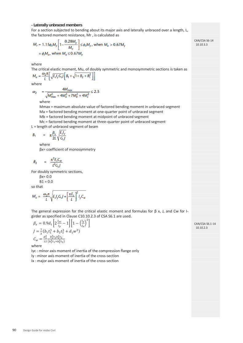
90 Design Guide for midas Civil
- Laterally unbraced members For a section subjected to bending about its major axis and laterally unbraced over a length, L, the factored moment resistance, Mr , is calculated as
where The critical elastic moment, Mu, of doubly symmetric and monosymmetric sections is taken as
where
where Mmax = maximum absolute value of factored bending moment in unbraced segment Ma = factored bending moment at one-quarter point of unbraced segment Mb = factored bending moment at midpoint of unbraced segment Mc = factored bending moment at three-quarter point of unbraced segment
L = length of unbraced segment of beam
where βx= coefficient of monosymmetry
For doubly symmetric sections,
βx= 0.0 B1 = 0.0
so that
The general expression for the critical elastic moment and formulas for β x, J, and Cw for I-girder as specified in Clause C10.10.2.3 of CSA S6.1 are used.
where Iyc : minor axis moment of inertia of the compression flange only Iy : minor axis moment of inertia of the cross-section Ix : major axis moment of inertia of the cross-section
CAN/CSA S6-14 10.10.3.3
CAN/CSA S6.1-14 10.10.2.3

91 Chapter 2. Steel Composite I-Girder Design – CAN/CSA S6-14
(3) Class 4 sections For beams and girders with continuous lateral support provided to the compression flange, with webs that meet the requirements of Class 3, and whose flanges exceed the slenderness limits of Class 3, the factored moment resistances is computed as for a Class 3 section, except that the elastic section modulus, S, is replaced by an effective section modulus, Se, determined using an effective projecting flange width of , for flanges supported along one edge. However, the projecting flange width shall not exceed 30t. - Bending about the minor axis For a section subjected to bending about its minor axis, whether laterally braced or unbraced, the factored resistance, Mr, shall be calculated as
(4) Stiffened plate girders - Width-to-thickness ratio of flanges The program checks if stiffened plate girders have Class 1, 2, or 3 flanges. - Width-to-thickness ratios of webs The width-to-thickness ratio of a transversely stiffened web, h/w, without longitudinal stiffeners, shall not exceed . If this requirement is not satisfied, the section is not valid. Therefore, the moment resistance check is skipped. The following provision of CAN/CSA S6-14 is not supported in the program. “In determining a width-to-thickness ratio, Fy may be replaced by the maximum compressive stress due to the factored ULS loads if the maximum shear at the FLS does not exceed Vr calculated in accordance with Clause 10.10.5.1, taking Ft = 0 and φs = 1.0.” When a longitudinal stiffener is provided, the width-to-thickness ratio, h/w, shall not exceed
. If this requirement is not satisfied, the section is not valid. Therefore, the moment resistance check is skipped.
CAN/CSA S6-14 10.10.3.4
CAN/CSA S6-14 10.10.3.5
CAN/CSA S6-14 10.10.4.1
CAN/CSA S6-14 10.10.4.1 10.17.2.5

92 Design Guide for midas Civil
- Moment resistance The moment resistance, Mr is calculated in the same way as Class 3 sections. If longitudinal stiffeners are not provided and , the moment resistance, calculated for the compression flange, is reduced by the following factor.
3.1.2 Shear (1) Factored shear resistance The factored shear resistance of the web of a flexural member, Vr , is taken as
where Aw, the shear area, is calculated using d for rolled shapes and h for fabricated or manufactured girders, and Fs , the ultimate shear stress, is equal to Fcr + Ft , where Fcr and Ft are taken as follows:
For unstiffened webs, a/h is considered infinite, so that kv = 5.34. At girder end panels and adjacent to large openings in the web, the resistance shall be calculated using Ft = 0. However, there is no consideration about the end panels and openings in the web in the program. (2) Combined shear and moment When subject to the simultaneous action of shear and moment, transversely stiffened webs that depend on tension field action to carry shear, i.e., with , are proportioned so that
CAN/CSA S6-14 10.10.4.3
CAN/CSA S6-14 10.10.5.1
CAN/CSA S6-14 10.10.5.2

93 Chapter 2. Steel Composite I-Girder Design – CAN/CSA S6-14
(3) Intermediate transverse stiffeners The distance between stiffeners, a, shall not exceed when h/w is greater than 150 and shall not exceed 3h when h/w is less than or equal to 150. Intermediate transverse stiffeners provided on one or both sides of the web are proportioned so that
I is taken about an axis at the mid-plane of the web for stiffener pairs or at the near face of the web for single stiffeners.
Vf / Vr = the ratio at the end of element
D = 1.0 for stiffeners provided in pairs = 2.4 for single-plate stiffeners Single-angle stiffeners are not supported.
The width of a plate used as a stiffener shall not be less than 50 mm plus h/30 and shall not be less than one-quarter of the full width of the flange. The width-to-thickness ratio of intermediate transverse stiffeners shall not exceed . The projecting stiffener width shall not exceed 30t. (4) Longitudinal web stiffeners The spacing, a, of transverse stiffeners of longitudinally stiffened webs shall not exceed 1.5hp , where hp is the maximum subpanel depth. The total web depth, h, is used in determining the shear capacity, Vr, of longitudinally stiffened girders. Longitudinal stiffeners shall be proportioned so that (a) the stiffener width-to-thickness ratio does not exceed ; (b) the projecting stiffener width is less than or equal to 30t;
where I and r are calculated about a centroidal axis parallel to the web for a section comprising the stiffener or stiffeners and a strip of web 10w wide on each side. Additional requirements of transverse stiffeners for longitudinally stiffened webs are not checked by the program. (5) Bearing stiffeners Bearing stiffener check is not supported in the program.
CAN/CSA S6-14 10.10.6.1
CAN/CSA S6-14 10.10.6.2
CAN/CSA S6-14 10.10.7.1
CAN/CSA S6-14 10.10.7.2

94 Design Guide for midas Civil
4. Horizontally curved I-girders 4.1 Non-composite girder design
4.1.1 Limits of applicability The following requirements shall apply: (a) The absolute value of the ratio of the torsional warping normal stress to the normal flexural stress shall, as far as possible, not exceed 0.5 at any point in the girder. This should be checked separately by the user. (b) The unbraced length between cross-frames shall not exceed 25 times the width of the flange or 0.1 times the mean radius of the girder. This should be checked separately by the user. (c) Flanges shall be Class 3 or better. This is checked by the program. 4.1.2 Flanges Flanges are proportioned to satisfy the following requirements:(a) Strength of either flange:
where Mfx = factored bending moment due to flexure Mrx = φsFy Sx
where Sx = elastic section modulus of the girder about its major axis
Mfw = factored bending moment in the flange due to torsional warping. Mfw is taken as regardless of the intermediate lateral restraint.
Where L = the distance between lateral restraintswr = the lateral load on the flange is a distributed lateral load, wr = Mfx/hR. Mfx = the moment in the vertical plane on the girder h = the clear depth of web between flanges R = the radius of curvature of the girder web (user input)
Mry = φsFy Sy where Sy = elastic section modulus of the flanges only about an axis in the plane tangent to the web of the girder
(b) Stability of compression flange:
where
where
wc = 0.5 where the lateral bending moment in the flange has major reversals, but 1.0 where the lateral bending moment does not have major reversals
CAN/CSA S6-14 10.13.6.1.1
CAN/CSA S6-14 10.13.6.1.2

95 Chapter 2. Steel Composite I-Girder Design – CAN/CSA S6-14
4.1.3 Webs The factored shear resistance is calculated in accordance with the provision for straight girders. The following requirements are also applied: (a) Webs without stiffeners: Tension-field action is neglected in webs without transverse
stiffeners. (b) Webs with transverse stiffeners only:
(i) Tension-field action is included in the calculated resistance when the geometry satisfies all of the following: (1) web slenderness h/w ≤ 160; (2) ratio of braced length to radius of horizontal curvature of the girder, Lb/R ≤ 0.1; and (3) transverse stiffener spacing a/h ≤ 3.
(ii) When subject to the simultaneous action of shear and moment, transversely stiffened webs that depend on tension-field action to carry shear is proportioned so that
(c) Webs with transverse and longitudinal stiffeners: When the longitudinal stiffeners are provided at a distance 0.2h from the compression flange, the program checks the web slenderness ratio satisfies the following condition.
When longitudinal stiffeners are located 0.2h from both the compression flange and the tension flange, the program checks if the web slenderness ratio does not exceed . Tension-field action is neglected. (d) Proportioning of transverse web stiffeners: the program checks if stiffeners are proportioned so that
I is taken about an axis at the mid-plane of the web for stiffener pairs, or at the near face of the web for single stiffeners. Where transversely stiffened webs depend on tension-field action to carry the applied shear, the program also checks if the transverse stiffeners are proportioned so that.
CAN/CSA S6-14 10.13.6.1.3

96 Design Guide for midas Civil
Vf / Vr = the ratio at the end of element
D = 1.0 for stiffeners provided in pairs = 2.4 for single-plate stiffeners Single-angle stiffeners are not supported.
The width of a plate used as a stiffener shall not be less than 50 mm plus h/30 and shall not be less than one-quarter of the full width of the flange. The width-to-thickness ratio of intermediate transverse stiffeners shall not exceed . The projecting stiffener width shall not exceed 30t. (e) The program checks if longitudinal stiffeners are proportioned so that
(a) the stiffener width-to-thickness ratio does not exceed ; (b) the projecting stiffener width is less than or equal to 30t;
where I and r are calculated about a centroidal axis parallel to the web for a section comprising the stiffener or stiffeners and a strip of web 10w wide on each side.
(f) Monosymmetric sections: the program does not check if the slenderness ratio of the compression portion of webs of monosymmetric sections with an axis of symmetry in the plane of loading does not exceed one-half of the applicable value specified in Item (a), (b), or (c). This should be separately checked by the user.
4.2 Composite I-girders 4.2.1 Webs The web of the steel girder is designed to carry the entire vertical shear in accordance with Clause 4.1.3 of this document. 4.2.2 Flanges The program checks if flanges are Class 3 or better and meet the strength and stability requirements of Clause 4.1.2 of this document. 4.2.3 Shear connectors The program checks if shear connectors meet the requirements of Clauses 2.1 and 2.2 of this document.
CAN/CSA S6-14 10.13.6.2.2 10.13.6.1.3
CAN/CSA S6-14 10.13.6.2.3 10.13.6.1.2
CAN/CSA S6-14 10.13.6.2.4 10.11.8 10.17.2.7

Chapter 2. Steel Composite I-Girder Design : CAN/CSA S6-14
Steel Composite Design Result
97Chapter 2. Steel Composite I-Girder Design – CAN/CSA S6-14
1. Ultimate Limit State Result 1.1 Flexure
(1) Result Table As shown in the table below, the results can be checked in the result table.
Design > Composite Design > Design Result Tables > Ultimate Limit State (flexure)…
Figure 1.37 Result Table for Ultimate Limit State of Flexure
Where,
Type: Load combination type (Fx-max, Fx-min, ... Mz-min). When a moving load case is included, there are 12 sets of concurrent forces. Load combination type shows which sets of concurrent forces give critical forces.
Top Class: Class of top flange Bot Class: Class of bottom flange Web Class: Class of web
My : yield moment
Mp : plastic moment. This is provided for Class 1 and 2 sections only.
Mf : factored bending moment
Mr : factored moment resistance of member

98 Design Guide for midas Civil
(2) Excel Report The results can be viewed in an Excel Report as shown below.
Figure 1.38 Excel Report for Ultimate Limit State of Negative Moment

99 Chapter 2. Steel Composite I-Girder Design – CAN/CSA S6-14
1.2 Shear (1) Result Table As shown in the table below, the results can be checked in the result table.
Design > Composite Design > Design Result Tables > Ultimate Limit State (shear)…
Figure 1.39 Result Table for Ultimate Limit State of Shear
Where,
Vf : factored shear force
Vr : factored shear resistance
Mf : factored bending moment
Mr : factored moment resistance of member
Vf/Vr : shear check ratio
Comb. : combined shear and moment check ratio
(2) Excel Report The results can be viewed in an Excel Report as shown below.
Figure 1.40 Excel Report for Ultimate Limit State of Shear

100 Design Guide for midas Civil
2. Service Limit State Result (1) Result Table
The results can be viewed in an Excel Report as shown below.
Design > Composite Design > Design Result Tables > Service Limit State…
Figure 1.41 Result Table for Service Limit State Where,
Stress 0.90Fy : limit stress in the flange of the steel section to control permanent deflections Md : bending moment at SLS due to dead load, steel section only S : elastic section modulus of steel section Msd : bending moment at SLS due to superimposed dead load, composite section S3n : elastic modulus of section comprising the steel beam and the concrete slab, calculated using amodular ratio of 3n, long-term load, positive moment ML : bending moment at SLS due to live load, composite section Sn : elastic modulus of section comprising the steel beam and the concrete slab, calculated using amodular ratio of n, short-term load, positive moment S’ : elastic modulus of composite section comprising the steel section and reinforcement, negative moment
(2) Excel Report
The results can be viewed in an Excel Report as shown below.
Figure 1.42 Excel Report for Serviceability Limit State

101 Chapter 2. Steel Composite I-Girder Design – CAN/CSA S6-14
3. Constructibility Result 3.1 Flexure
(1) Result Table The results can be viewed in a result table as shown below.
Design > Composite Design > Design Result Tables > Construction Stage (flexure)...
Figure 1.43 Result Table for Constructibility Limit State of flexure
Where,
Mfy : factored bending moment about the y-axis of the cross-section Mry : factored moment resistance about the y-axis of the cross-section Mfz : factored bending moment about the z-axis of the cross-section Mrz : factored moment resistance about the z-axis of the cross-section Comb.1 : strength check ratio of flange for the combined moments Comb.2 : stability check ratio of compression flange for the combined moments (2) Excel Report The results can be viewed in an Excel Report as shown below.
Figure 1.44 Excel Report for Constructibility of Negative Moment

102 Design Guide for midas Civil
3.2 Shear (1) Result Table The results can be viewed in a result table as shown below.
Design > Composite Design > Design Result Tables > Construction Stage (shear)...
Figure 1.45 Result Table for Constructibility of Shear
Where,
Vf : factored shear force
Vr : factored shear resistance
Mf : factored bending moment
Mr : factored moment resistance of member
Vf/Vr : shear check ratio
Mf/Mr : moment check ratio
Comb. : combined shear and moment check ratio
(2) Excel Report The results can be viewed in an Excel Report as shown below.
Figure 1.46 Excel Report for Constructibility of Shear

103 Chapter 2. Steel Composite I-Girder Design – CAN/CSA S6-14
4. Fatigue Limit State Result (1) Result Table The results can be viewed in a result table as shown below.
Design > Composite Design > Design Result Tables > Fatigue Limit State...
Figure 1.47 Result Table for Fatigue Limit State
Where,
Lcom : Load combinations used in the calculation
fsr : calculated FLS stress range at the detail due to passage of the CL-W Truck
Fsr : fatigue stress range resistance
tau_rs: fatigue shear stress range for the stud shear connectors
Vsc : range of design shear force at the section along the length of the beam where the fatigue resistance of the shear connectors is being evaluated
(2) Excel Report The results can be viewed in an Excel Report as shown below.
Figure 1.48 Excel Report for Fatigue Limit State

104 Design Guide for midas Civil
5. Shear Connector Result (1) Result Table
The results can be viewed in a result table as shown below.
Design > Composite Design > Design Result Tables > Shear Connector...
Figure 1.49 Result Table for Shear Connector
Where,
h/d : height to diameter ratio of shear connector
qr : factored shear resistance of shear connectors
N : number of shear connectors entered in shear span
Nreq : required number of shear connectors in shear span
(2) Excel Report
The results can be viewed in an Excel Report as shown below.
Figure 1.50 Excel Report for Shear Connector

105 Chapter 2. Steel Composite I-Girder Design – CAN/CSA S6-14
6. Stiffener Result (1) Result Table
The results can be viewed in a result table as shown below.
Design > Composite Design > Design Result Tables > Transverse Stiffener...
Figure 1.51 Result Table for Stiffener
Where, h/w : ratio of clear depth of web to web thickness h/w_lim : 150, Web stiffeners are not required when the unstiffened shear resistance exceeds the factored shear and h/w ≤ 150. a : stiffener spacing a_lim : limit of stiffener spacing as per clause 10.10.6.1 As : area of stiffener or pair of stiffeners It : moment of inertia of transverse stiffener It_lim : limit of moment of inertia of transverse stiffener as per clause 10.10.6.2 w/t : width-to-thickness ratio of intermediate transverse stiffeners 200/sqrt(Fy) : limit of width-to-thickness ratio of intermediate transverse stiffeners as per clause10.10.6.2 wp : projecting stiffener width 30t : limit of projecting stiffener width as per clause 10.10.6.2
(2) Excel Report
The results can be viewed in an Excel Report as shown below.
Figure 1.52 Excel Report for Stiffener

106 Design Guide for midas Civil
7. Total Checking
(1) Result Table
Design > Composite Design > Design Result Table...
Summary results for each member can be viewed in a result table as shown below.
Figure 1.53 Result Table for Toal Checking

CAN/CSA S6 -14
Chapter 3.
Steel CompositeBox Girder Design

Steel Composite Box-Girder Bridge
Check Constructability
Check Shear Connector
Steel Composite Box Girder DesignChapter 3.

Chapter 3.Steel Composite Box Girder Design : CAN/CSA S6-14
Introduction
Chapter 3.Steel Composite Box Girder Design – CAN/CSA S6-14 109
1. CAN/CSA S6-14 Steel Composite Box Girder 1.1 Check List of CAN/CSA S6-14 Steel Composite Box Girder For CAN/CSA S6-14 Steel Composite Design, Limit State Design is applied. The criteria that Steel Composite Box-Girder must follow for Limit State Design is as follows.
(1) Ultimate Limit State Review on bending strength, lateral torsional buckling and shear strength (2) Serviceability Limit State Review on permanent deformation (3) Constructibility Review on bending and shear occurring from load combinations during construction stages (4) Fatigue Limit State Review on fatigue in steel and concrete materials in Steel Composite girder
1.2 Classification of Steel Composite Steel Composite section can be categorized by the following classification groups.
(1) Section Shape Type There are three main section shape types in midas Civil; I, Box and Tub shapes. In the case ofbox and tub sections, there are two more cases, single or multiple box section.
I Box Tub
Figure 1.1 Section Shape Type (2) Moment Type : Positive / Negative For continuous beams, negative moments may occur around interior supports. Design codemay apply different formulas for these cases. (3) Bridge Type : Straight / Curved Based on the horizontal alignment of a bridge, it can be classified as either straight or curved. The program recognizes curved bridges based on the input of the girder radius for each element.

110 Design Guide for midas Civil
(4) Classification of Cross-sections: Class 1 / Class 2 / Class 3 / Class 4 Structural sections shall be designated as Class 1, 2, 3, or 4 depending on the width-to-thickness ratio of the elements that make up the cross-section and on the conditions ofloading.
Table 1.1 Steel Section Classification
Type Description
Class 1 A Class 1 section is one that will attain the plastic moment capacity, adjusted for the presence of axial force if necessary, and permit subsequent redistribution of bending moment.
Class 2 A Class 2 section is one that will attain the plastic moment capacity, adjusted for the presence of axial force if necessary, but not necessarily permit subsequent moment redistribution.
Class 3 A Class 3 section is one that will attain the yield moment capacity, adjusted for the presence of axial force if necessary.
Class 4 A Class 4 section is one in which the slenderness of the elements making up the cross-section exceeds the limits of Class 3.
1.3 Stiffeners of Steel Composite The program considers transverse and longitudinal stiffeners.
Table 1.2 Types of Stiffeners
Type Description
Transverse Stiffeners
Transverse stiffeners are usually provided to increase shear resistance by tension field action. These work as anchors for the tension so that post buckling shear resistance can be developed. It should be noted that elastic web shear buckling cannot be prevented by transverse stiffeners.
Longitudinal Stiffeners
Longitudinal stiffeners may be provided to increase flexural resistance by preventing local buckling. These work as restraining boundaries for compression elements so that inelastic flexural buckling stress can be developed in a web. It consists of either a plate welded longitudinally to one side of the web, or a bolted angle.
Figure 1.2 Longitudinal Stiffener and Transverse Stiffener
CAN/CSA S6-14 10.9.2.1

111Chapter 3.Steel Composite Box Girder Design – CAN/CSA S6-14
2. Considerations of Steel Composite Design 2.1 Construction Stage for steel composite During the construction of a steel composite bridge, the steel girder is constructed before theconstruction of the concrete deck of the upper part of the structure. The steel composite sectionis divided into three major steps.
Table 1.3 Construction Stage for Steel Composite Section
Construction stage for steel composite section
Description
Only Steel Girder (non-composite)
Only the steel girder has been constructed.
Steel girder and concrete deck
as load (non-composite)
Although the concrete deck has been constructed, it has not hardened yet. Therefore, the weight of the wet concrete is applied to the steel girder as a load condition.
Steel girder and concrete deck
as member (composite)
After concrete is hardened, the strength and stiffness are formed. Hereafter, the steel girder and concrete deck work as a complete composite section.
2.2 Time Dependent Material ▪ Steel composite section is composed of steel and concrete. Concrete is a time dependentmaterial and transforms due to creep and shrinkage. Also, the restraints imposed by the shearconnectors cause additional stresses within the composite section. Therefore, time dependentcharacteristics (creep and shrinkage) must be taken into consideration. ▪ Modular ratio is the ratio of modulus of elasticity of steel to that of concrete. The short-termmodular ratio "n" is used for transient loads in the program. Long-term modular ratio "3n" is usedfor permanent loads acting after composite action.
3. Calculation of Plastic Moment and Yield Moment 3.1 Section Classification
The steel section is classified in accordance with Clause 10.9.2 of CAN/CSA S6-14. Theclassification is carried out separately for positive and negative bending for both compositeand non-composite sections. The classification of a cross-section depends on the width tothickness ratio of the parts subject to compression. A cross-section is classified according tothe highest (least favorable) class of its compression parts. For calculating the limiting width-to-thickness ratios of the web of monosymmetric steelsections, h is replaced by 2dc. However, for the classification of composite section, the h is
CAN/CSA S6-14 10.9.2.1 CAN/CSA S6-14 10.10.2.1

112 Design Guide for midas Civil
used for the web. The resistance of the top flange of the composite section under positive moment is assumedas not being limited by its local buckling resistance since it is restrained by effective attachment to a concrete flange by shear connectors. The top flange is always classified as Class 1.
3.2 Plastic Moment (Mp) of Composite Section in Positive Flexure
If the positive moment is applied on a class 1 or class 2 section, MP is calculated as shown inTable 1.4.
Figure 1.3 Case of calculation of Mp in positive moment
Table 1.4 Calculation of and Mp for section in Positive Flexure
Case PNA Condition and pM
In Web wt PP
rtrbsc PPPP
]1[2 w
rbrtsct
PPPPPPD
Y
])([2
22YtY
DP
M w
][ ttwwrbrbrtrtss dPdPdPdPdP
In Top flange
cwt PPP
rtrbs PPP
])([2
22YtY
tP
Mc
c
][ ttwwrbrbrtrtss dPdPdPdPdP
Concrete Deck, Below Prb
cwt PPP
rtrbss
rb PPPtc
s
s
tPY
M2
2
][ ttwwccrbrbrtrt dPdPdPdPdP
Concrete Deck, at Prb
rbcwt PPPP
rtss
rb PPtc
rbCY
s
s
tPY
M2
2
][ ttwwccrtrt dPdPdPdP

113Chapter 3.Steel Composite Box Girder Design – CAN/CSA S6-14
Concrete Deck, Above Prb Below Prt
rbcwt PPPP
rtss
rt PPtc
s
rbrttwcs P
PPPPPtY )(
s
s
tPY
M2
2
][ ttwwccrbrbrtrt dPdPdPdPdP
Concrete Deck, at Prt
rtrbcwt PPPPP
ss
rt Ptc
rtCY
s
s
tPY
M2
2
][ ttwwccrbrb dPdPdPdP
Concrete Deck, Above Prt
rtrbcwt PPPPP
ss
rt Ptc
s
rttwcrbs P
PPPPPtY )(
s
s
tPY
M2
2
][ ttwwccrbrbrtrt dPdPdPdPdP
Where, : Distance from the plastic neutral axis to the centerline of the top layer of longitudinal concrete
deck. : Distance from the plastic neutral axis to the centerline of the bottom layer of longitudinal
concrete deck. : Distance from the plastic neutral axis to the midthickness of the tension flange. : Distance from the plastic neutral axis to middepth of the web. : Distance from the plastic neutral axis to midthickness of the compression flange. : Distance from the plastic neutral axis to midthickness of the concrete deck.
(by reinforcement) (by reinforcement)
(by steel girder)
(by steel girder) (by steel girder)
(by concrete slab)
3.3 Plastic Moment (Mp) of Composite Section in Negative Flexure Under negative moment, Mp is calculated by either of the two following methods. Please refer to Table 1.5 for the equations.
Figure 1.4 Case of calculation of Mp in Negative Moment

114 Design Guide for midas Civil
Table 1.5 Calculation of and Mp for section in Negative Flexure
Case PNA Condition and pM
In Web rtrbtwc PPPPP
In Top flange rtrbtwc PPPPP
Where,
(by reinforcement) (by reinforcement)
(by steel girder) (by steel girder)
(by steel girder)

Chapter 3. Steel Composite Box Girder Design : CAN/CSA S6-14
Modeling and Design Variables
Chapter 3.Steel Composite Box Girder Design – CAN/CSA S6-14 115
1. Modeling Design Variables In this chapter, the design variable values, the meaning behind the design requirements, and the design process for Steel Composite Design in midas Civil are explained.
1.1. Composite Section Data The steel composite section is mainly composed of steel girder and concrete slab. Stiffeners can be added to steel girder section while longitudinal reinforcement can be added to reinforce concrete slab. In this section, the input methods for these sections and the meaning and application of design variables are explained.
1.1.1 Composite Section (1) Composite Section Data
Properties > Section > Section Properties> Add > Composite Tab
Figure 1.5 Section Data Dialog Box
1.1.1 Composite Section (1) Composite Section Data
1) The value of Bc for the slab is used as the effective width of the concrete deck. 2) Multiple Modulus of Elasticity Option To design the steel composite section, the modulus of elasticity for short-term and long-term effect in creep and shrinkage can be input. The modulus of elasticity input here is applied for construction stage analysis of Steel Composite section as shown in Figure 1.6.
Figure 1.6 Elastic Modulus ratio for Construction Stage

116 Design Guide for midas Civil
(2) Section Stiffener
Properties > Section > Section Properties> Add > Composite Tab > Stiffeners Button...
Figure 1.7 Section Stiffener Dialog Box
1.1.2 Longitudinal Reinforcement
Design > Composite Design > Longitudinal
Reinforcement ...
Figure 1.8 Longitudinal Reinforcement Dialog Box
(2) Section Stiffener (Longitudinal)
1) Types of longitudinal stiffeners that are useable are Flat, Tee, and U-Rib. 2) For I sections, stiffeners can be added on either side of the web. For Box/Tub sections, upper and lower flanges can be installed as well as the web panel. 3) When the check box under ‘c’ column is checked on, the stiffness value of the stiffener is considered in analysis. Otherwise, the value is not considered for analysis. Regardless of whether or not the check box is checked on or off, longitudinal stiffeners are considered in design. It is also required for classifying the interior panels in shear check as stiffened/unstiffened.
1.1.2 Longitudinal Reinforcement
In a steel composite section, the longitudinal reinforcements are arranged within the concrete deck. The moment resistance is calculated as shown in Table 1.6.
Table 1.6 Applicability of concrete and reinforcement for the calculation of moment resistance
Case Positive Bending
Negative Bending
Figure
Concrete Slab Applied None
Rebar Applied Applied

117Chapter 3.Steel Composite Box Girder Design – CAN/CSA S6-14
1.1.3 Transverse Stiffener (1) Transverse Stiffener
Design > Composite Design > Transverse Stiffener ...
Figure 1.9 Transverse Stiffener Dialog Box
Figure 1.10 Stiffener Type Dialog Box
1.1.3 Transverse Stiffener
Figure 1.9 shows the window in which users can arrange transverse stiffeners in steel composite section. When the transverse stiffeners are installed, the existence and spacing between stiffeners determine whether the web is stiffened or unstiffened under ultimate limit state.
Figure 1.11 Transverse Stiffener Parameters
Stiffener Type 1) One / Two Stiffener Option Button Choose between one or two stiffeners. Transverse stiffeners can be provided on one or both sides of the web.
2) Pitch Pitch refers to transverse stiffener spacing. At the ultimate limit state, this can be used to distinguish between stiffened and unstiffened webs or calculate shear strength of the web.

118 Design Guide for midas Civil
1.2. Design Material Data For the design of steel composite section, construction stage and time dependent material properties of concrete can be applied. In this section, the input method for the time dependent properties of concrete and material data for steel composite section is explained.
Contents Explanation
1.2.1 Time Dependent Material (1) Creep/Shrinkage
Properties > Time Dependent Material > Creep/Shrinkage ...
Figure 1.12 Add/Modify Time Dependent Material Dialog Box
(Creep/Shrinkage)
(2) Comp. Strength
Properties > Time Dependent Material > Comp. Strength ...
Figure 1.13 Add/Modify Time Dependent Material Dialog Box
(Compression Strength)
1.2.1 Time Dependent Material (1) Creep/Shrinkage The time dependent properties of concrete, such as creep and shrinkage, are defined. During construction stage analysis of bridges, these properties are utilized for concrete material.
(2) Comp. Strength
In order to reflect the change in the modulus of elasticity of concrete, the change in compressive strength or modulus of elasticity is defined. Aging effects may vary for each construction stage since concrete is poured at different locations.

119Chapter 3.Steel Composite Box Girder Design – CAN/CSA S6-14
Contents Explanation
1.2.2 Modify Composite Material (1) Modify Composite Material
Design > Composite Design > Design Material ...
Figure 1.14 Modify Composite Material Dialog Box
1.2.2 Modify Composite Material The materials utilized for steel composite sections are provided in the SRC material properties. The materials should be defined as SRC Type.
(1) Modify Composite Material Figure 1.14 shows the dialog box where users can type in material characteristics for the steel composite section design. The material property values entered will have a priority over the values entered in the Material Data dialog box.
1) Steel Material Selection Define modulus of elasticity, yield strength and tensile strength of steel for design purpose. In the current version, different yield strengths for different thicknesses of steel are not supported.
2) Concrete Material Selection Define compressive strength of concrete slab for design purpose.
3) Reinforcement Selection Define yield strength of reinforcement in the slab.

120 Design Guide for midas Civil
1.3. Design Parameters for Composite Section
Contents Explanation
1.3.1 Design Parameter
Design > Composite Design > Design Parameters ...
Figure 1.15 Composite Steel Girder Design Parameter Dialog Box
1.3.2 Unbraced Length
Design > Composite Design > Unbraced Length ...
Figure 1.16 Unbraced Length Dialog Box
1.3.1 Design Parameter
(1) Strength Resistance Factor Strength Resistance Factor is defined.
By clicking , the resistance factors are automatically set to the default values defined in CAN/CSA S6-14. The values can also be modified or entered manually.
(2) Girder Type for Box/Tub Section If Single Box Section is selected, the following clauses are applied for the box/ tub girder design. 10.12.8.4 Moment resistances 10.12.8.5 Combined shear and torsion
(3) Options For Construction Stage
If this option is checked, ULS check for steel section only during construction is performed.
(4) Design Parameters Design and result outputs are generated for the limit states checked in the Design Parameters.
1.3.2 Unbraced Length Unbraced length for steel composite section is considered. The value input here has higher priority than the value calculated from Span Group.
(1) Lb Laterally Unbraced Length is used to calculate lateral torsional buckling resistance in compression flange of I Girder or top flange of Tub Girder. Laterally Unbraced Length is automatically determined using ‘Span Information’ and by assigning member type of cross-frames as ‘Brace’ using the Common Parameter > Modify Member Type function. The user can define/modify the laterally unbraced lengths.

121Chapter 3.Steel Composite Box Girder Design – CAN/CSA S6-14
Contents Explanation
1.3.3 Shear Connectors
Design > Composite Design > Shear Connectors ...
Figure 1.17 Shear Connector Dialog Box
1.3.3 Shear Connectors In this program, studs are used for shear connectors. The parameters used for calculation are shown below.
(1) Category Category for fatigue check, it is fixed as D. (2) Fu Minimum tensile strength of the stud steel (3) Shear Connector Parameters
Figure 1.18 Shear Connector Parameters
(4) Length Between Maximum Moment and Zero Moment The Length between Maximum Moment and Zero Moment needs to be inputted by users to verify pitch as per ultimate limit state.

122 Design Guide for midas Civil
Contents Explanation
1.3.4 Fatigue Parameter
Design > Composite Design > Fatigue Parameter ...
Figure 1.19 Fatigue Parameters Dialog Box
1.3.5 Span Information
Structure > Wizard > Composite Bridge > Span Information ...
Figure 1.20 Span Information Dialog Box
1.3.4 Fatigue Parameter (1) Weight of Truck(W)
Load level in CL-W, kN (2) Design Life(y)
Design life, years (3) Number of Stress Cycles(Nd) Number of design stress cycles experienced for each passage of the design truck (4) Reduction Factor(ρ) (5) Average Daily Truck Traffic
1.3.5 Span Information The elements of composite sections are defined as one Span Group. The Span Group will serve the following functions.
- Calculation of Unbraced Length When assigning a span group, support properties are considered for calculating the unbraced length. The unbraced length can also be manually inputted once the corresponding support conditions under the support column are selected. Using the span parameters inputted, the unbraced length can be calculated automatically. However, if the unbraced length is inputted in Section 1.3.2, this value will be applied as the unbraced length first.

123Chapter 3.Steel Composite Box Girder Design – CAN/CSA S6-14
Contents Explanation
1.3.6 Curved Bridge Information
Design > Composite Design > Curved Bridge Info ...
Figure 1.21 Curved Bridge Information Dialog Box
1.3.7 Design Force/Moment
Design > Composite Design > Design Tables > Design Force/Moment...
Figure 1.22 Design Force/Moment Dialog Box
1.3.6 Curved Bridge Information Once the girder radius value of the element units in the steel composite section is entered, the corresponding elements are categorized as curved bridges.
(1) Radius is used to determine the factored bending moment in the flange due to torsional warping. (2) In the current version, the curve type of convex or concave is not used.
1.3.7 Design Force/Moment This feature displays design member forces (strong axis moment, My), weak-axis moment (Mz) and shear stress (VU) for the local axis of elements under selected load combination of steel composite section.

124 Design Guide for midas Civil
1.4 Load Combination for steel composite section 1.4.1 Application of load combination in midas Civil for CAN/CSA S6-14
(1) Application of load combinations and factors in midas Civil for CAN/CSA S6-14 The load combinations used for the review of each limit state are shown below.
Figure 1.23 Load factors and load combinations
Using the Auto Generation feature of the program, the load combinations regulated by the design code can be automatically generated. Load factors are considered for each load combinations in this program.
Figure 1.24 Live load factors ultimate limit states
Figure 1.25 Permanent loads — Maximum and minimum values of load factors for ULS
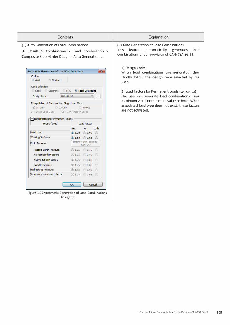
125Chapter 3.Steel Composite Box Girder Design – CAN/CSA S6-14
(1) Auto Generation of Load Combinations
Result > Combination > Load Combination > Composite Steel Girder Design > Auto Generation ...
Figure 1.26 Automatic Generation of Load Combinations
Dialog Box
(1) Auto Generation of Load Combinations This feature automatically generates load combinations under provision of CAN/CSA S6-14.
1) Design Code When load combinations are generated, they strictly follow the design code selected by the user. 2) Load Factors for Permanent Loads (αD, αE, αP) The user can generate load combinations using maximum value or minimum value or both. When associated load type does not exist, these factors are not activated.

126 Design Guide for midas Civil
1.4.2 Load combination type for steel composite design Load combination type must be assigned before performing design. When load combinations are generated by auto-generation, the load combination type is automatically assigned, but when load combinations are defined manually or modified, the load combination type should be assigned by the user. Load combinations used in the steel composite section design are categorized under Load Combination Type.
Contents Explanation
(1) Load Combination Type
Design > Composite Design > Load Combination Type...
Figure 1.27 Load Combination Type Dialog Box
(1) Load Combination Type 1) Ultimate Limit State Choose load combinations for use under review of ultimate limit state. 2) Service Limit State Choose load combinations for review of serviceability limit state. 3) Fatigue Limit State Choose load combinations for review in fatigue limit state.
1.5 Modeling Steel Composite Sections for Construction Stage Analysis In this section, methods of construction stage modeling, implementation of time-dependent material properties of concrete in steel composite section and 3 types of design member forces applied to steel composite section design are explained. Construction stages of steel composite section can be implemented differently for case 1 to 3 as in Table 1.7.
Table 1.7 Modeling Construction Stage Cases for Steel Composite Design
Case Construction Stage Time Dependent Material(Creep / Shrinkage)
Case 1 Defined
Defined
Case 2 Not Defined (Apply modular ratio of 3n)
Case 3 Not Defined Not Defined (Apply modular ratio of 3n)
1.5.1 Member forces and stresses used in steel composite section design
(1) Member forces For design of steel composite section, member forces per construction stage of steel composite section must be calculated. The program considers two main factors for design and review of construction stage of steel composite section. ▪Construction stages of steel composite section ▪Time dependent material properties of Concrete (Creep, Shrinkage and Compressive Strength)

127Chapter 3.Steel Composite Box Girder Design – CAN/CSA S6-14
Design member forces used for design of steel composite section are divided into three main categories. Table 1.8 Design Force and Moment for Steel Composite Design
Design Force/Moment Description
Dead (Before) Member forces due to permanent loads occurring before the concrete deck is activated. Only steel section properties are used to calculate stresses. ex) Self weight of steel and concrete deck
Dead (After) Member forces due to permanent loads occurring after concrete deck is activated Long term section properties of composite section are used. ex) Self weight of wearing surface and barrier
Short Term Member forces from the post-construction state and load cases not included in the above categories. Short term section properties of composite section are used. ex) Traffic loads, wind loads
When construction stages are included in the model in midas Civil, the design moments for Dead (Before) are taken as the moments of steel section due to Dead Load (CS) and Erection Load (CS) whose load type is Dead Load (D) and the design moments for Dead (After) are taken as the moments of composite section due to Erection Load (CS) whose load type is Dead Load of Component and Attachements (DC) or Dead Load of Wearing Surfaces and Utilities (DW). Example:
Permanent loads Load Type Analysis results
Load Factor
Design forces Stage 1
Steel only Stage 2
Composite Dead (Before)
Dead (After)
Self Weight of Steel Dead Load (CS) 100 100 1.1 110 Self Weight of Concrete Erection (D) 100 100 1.2 120
Self Weight of Barrier Erection (DC) 0 100 1.2 120 Self Weight of Wearing
Surface Erection (DW) 0 100 1.5 150
Sum 230 270
Above rule has changed in Civil 2018 (v1.2) in order to account for various erection sequence of slab. The design moments for Dead (Before) and Dead (After) are determined as shown in the table below.
Dead Load (CS) Erection Load (CS) Moments applied to steel section Dead (Before) Dead (Before) Moments applied to composite section Ignored Dead (After)
(2) Stress Bending stress used for design of steel composite section is calculated as follows:
Where,
Md : bending moment at SLS due to dead load, steel section only
Msd : bending moment at SLS due to superimposed dead load, composite section
ML : bending moment at SLS due to live load, composite section
S : elastic section modulus of steel section
S3n : elastic modulus of section comprising the steel beam and the concrete slab, calculated using a modular ratio of 3n, long-term load, positive moment

128 Design Guide for midas Civil
Sn : elastic modulus of section comprising the steel beam and the concrete slab, calculated using a modular ratio of n, short-term load, positive moment
S’ : elastic modulus of composite section comprising the steel section and reinforcement, negative moment 1.5.2 Case 1 In Case 1, construction stages and time dependent material properties of concrete (Creep/Shrinkage) are defined and Multiple Modulus of Elasticity is not checked on in the Section Data dialog. The effects of creep and shrinkage of concrete are directly calculated and checked by Creep Secondary (CS) or Shrinkage Secondary (CS) load cases. The Composite sections for Construction Stage function must be defined. Otherwise, the sections shall be excluded from design. Note that if time dependent material property information is inputted as well as long-term modulus of elasticity, long-term modulus of elasticity has higher priority in consideration of calculation.
Define Composite Section for Construction Stage
Contents Explanation
Composite Section for Construction Stage
Load >Load Type> Construction Stage > Composite Section for C.S...
Figure 1.28 Add/Modify Composite Section for
Construction Stage Dialog
Composite Section for Construction Stage For definition of composite section for construction stage, information in this window must be defined. (1) Active Stage Construction stage where steel composite section should be activated is inserted. (2) Construction sequence
1) "Material Type" column □ By choosing Element, material property of the element is used. □ By selecting Material, material information chosen under "Material" Column is applied with higher priority. 2) Composite Stage column Construction stages where steel girder and concrete slab should be activated are chosen separately. 3) Age column Age information when each part is activated is input. Information in this column has higher priority over the age input during definition of construction stage.

129Chapter 3.Steel Composite Box Girder Design – CAN/CSA S6-14
Define Erection Load
(1) Define Erection Load
Analysis > Analysis Control > Construction Stage > Load Cases to be Distinguished from Dead Load for C.S Output >Add (Modify/delete)...
Figure 1.29 Define Erection Load Dialog
1) Define Erection Load Erection Load is defined.
1) Load Type for C.S Determine the Load Type for the construction stages of the composite section. Load types are considered by the software for auto generation of load combinations. 2) Assignment Load Cases Define Erection Load by selecting and moving the Load Cases desired from the List of Load Case panel to the Selected Load Case panel.
1.5.3 Case 2 In Case 2, construction stages are defined without the time dependent material property (Creep/Shrinkage) information. Long term effects are considered using the long term modular ratio entered in the Section Data dialog box. Sections for different construction stages must be defined and differentiated using the Composite Section for Construction Stage definition. Otherwise, they will not be considered for the design check.
(1) Member forces under Dead (Before) Dead (Before) is applied before the concrete deck is activated. (Refer to Table 1.8 in the "Introduction") Self weight of steel and concrete belongs to Dead (Before).
(2) Member forces under Dead (After) The effects of Creep/Shrinkage are reflected by applying the ratio of elastic modulus that is inputted in the Section Data (Refer to Section 1.1.1 (1)) for the long-term stage. In other words, the Creep/Shrinkage effects are reflected by using the section information with the ratio of elastic modulus that considers the time dependent material property for the analysis and design. These long term modular ratios defined for considering creep and shrinkage, automatically generate Section Stiffness Scale Factors for the sections in which these are inputted. Section Stiffness Scale Factors need to be activated in the construction stages in accordance with the Composite Section for Construction Stage definition, i.e. the Section Stiffness Scale Factors are activated when the corresponding section becomes composite as per the definition of composite section for CS. Super-imposed dead loads, i.e. wearing surface, barrier belong to Dead (After).
(3) Short term member forces The ratio of elastic modulus of the composite section is calculated using the DB value inputted. All the load cases which are not activated in the Construction Stage are considered as the short-term loads.

130 Design Guide for midas Civil
1.5.4 Case 3 In case the construction stages are not defined, users can model and define steel composite sections by using the Load Case for Pre-Composite Section function.
Load > Load Type > Settlement/Misc. > Misc. > Pre-composite Section. For this case, short- and long-term ratios of elastic modulus defined in the section data (Refer to Section 1.1.1 (1)) are used. In this case, instead of member forces per construction stages, member forces under Dead (Before) is used to check the constructibility of the model.
(1) Member force under Dead (Before) In the Load Cases for Pre-Composite Section dialog box, users can define which load cases to account for the member forces and apply as Dead (Before) in design. Since this is for pre-composite state, the steel only section properties are used (Refer to Section 1.1.1 (1)).
Figure 1.30 Load Cases for Pre-Composite Section
(2) Member forces under Dead (After) Member forces under Dead (After) use the long term section properties. These loads should be separated from the short term member forces by the use of Analysis > Analysis Control > Boundary Change Assignment.
1) Data Selection Check the box corresponding to Section Stiffness Scale Factor. As explained earlier, Section Stiffness Scale Factors are used for considering the long term section properties.
2) Boundary Group Combination Create a boundary group combination considering the appropriate boundary groups from the boundary group list. The created boundary group combinations need to be selected for the post composite long term load cases. For the static load cases assigned with the section stiffness scale factor boundary groups, long term section property will be used.
Dead Load (Before)

131Chapter 3.Steel Composite Box Girder Design – CAN/CSA S6-14
Figure 1.31 Load Cases for Post-Composite Section
(3) Short-term member forces The ratio of elastic modulus from the database is used for the short-term loads of the composite section. All load cases are considered for the short-term loads except the ones considered for the Dead (Before) and Dead (After).
1.5.5 Torsional constant of tub girder before composite section
The torsional constant of a tub girder before the concrete slab is activated is somewhere between open section and closed section. Top flanges of tub section are restrained by the top lateral bracing system. The behaviour of a tub girder before the concrete deck has cured may be analyzed as a quasi-closed section by replacing the lateral bracing with an equivalent plate. In this version, the quasi-closed section method is not supported. The torsional constant is calculated based on closed section using the thickness of top flange. It is recommend that the user adjust the torsional constant using Stiffness Scale Factor.
Dead Load (After)

Chapter 3. Steel Composite Box Girder Design : CAN/CSA S6-14
Application of CAN/CSA S6-14
132Chapter 3. Steel Composite Box Girder Design – CAN/CSA S6-14
1. Composite Box Girder 1.1 Overview
1.1.1 General This design function applies to the design of simple and continuous composite box girder bridges of spans up to 110 m, consisting of one or more straight steel single-cell box girders, acting compositely with a concrete deck, and symmetrical about a vertical axis. The top of the box may be open with twin steel flanges or closed with a steel flange plate. (1) Proportioning The program checks if the steel section alone is proportioned to support all factored loads applied before the concrete is activated. The lateral restraint conditions existing when the different loads are applied are taken into account. The web of the steel section is designed to carry the total vertical shear and is proportioned in accordance with the requirements of Clauses 10.10.5 to 10.10.8 of CAN/CSA S6-14. The control of cracking of the slab is not taken into account. The program assumes that the whole width of slab is effective. (2) Effects of creep and shrinkage To account for the effect of creep due to that portion of dead load that is applied after the concrete slab is activated, time-dependent material properties can be applied or a modular ratio of 3n can be used in calculating the section properties. 1.1.2 Effective width of tension flanges The effective width of bottom flange plates in tension shall be taken as not more than one-fifth of the span for simply supported structures and not more than one-fifth of the distance between points of contraflexure under dead load for continuous structures. The program assumes that the whole width of tension flanges is effective. 1.1.3 Web plates Webs are proportioned in accordance with Clause 10.10 of CAN/CSA S6-14 and, for single box girders, both the web plates and the shear connectors are proportioned for the sum of the factored shears due to bending and torsion. The shear force to be considered on each web is Vf /cosθ , where Vf is one-half of the total vertical shear force at the ULS on one box girder and θ is the angle of inclination of the web plate to the vertical. The inclination of the web plates shall not exceed 1 horizontal to 4 vertical. The program does not check the inclination of the web plates.
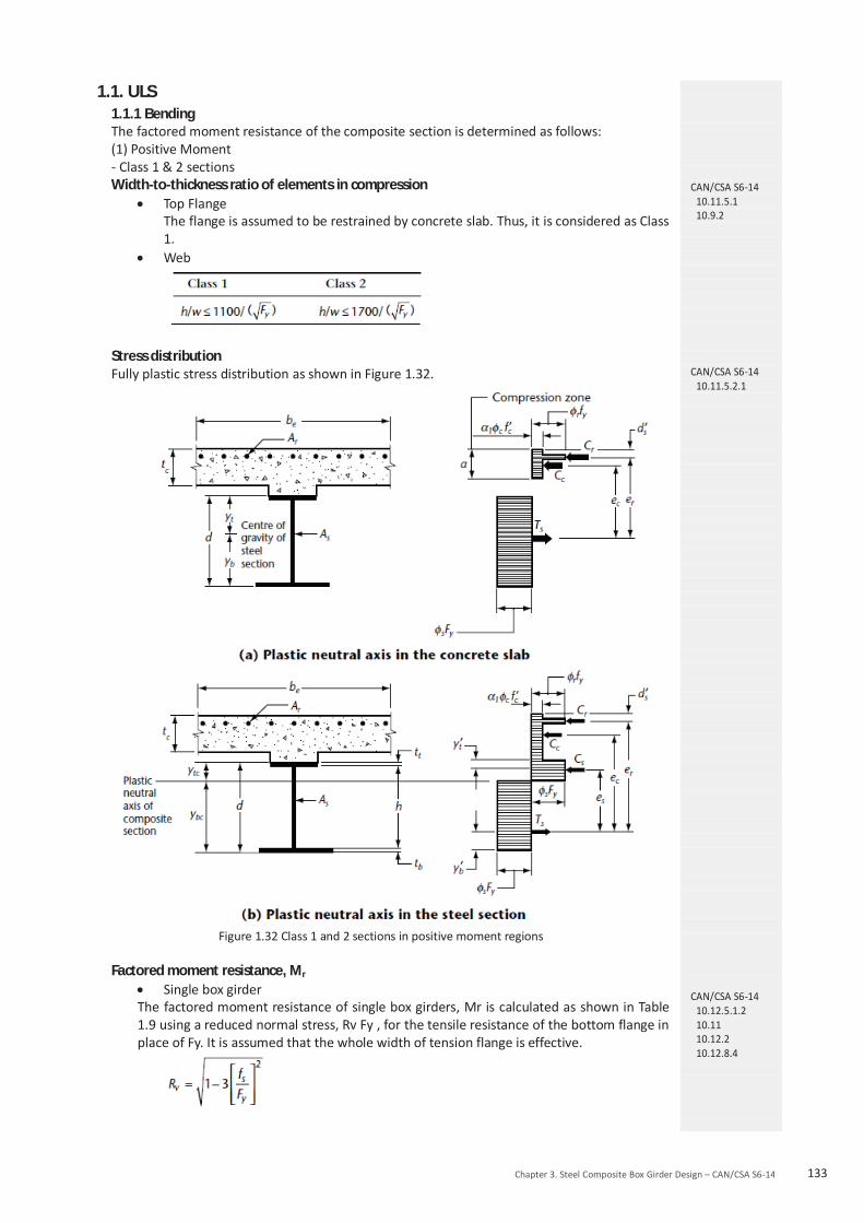
Chapter 3. Steel Composite Box Girder Design – CAN/CSA S6-14 133
1.1. ULS 1.1.1 Bending The factored moment resistance of the composite section is determined as follows: (1) Positive Moment - Class 1 & 2 sections Width-to-thickness ratio of elements in compression
Top Flange The flange is assumed to be restrained by concrete slab. Thus, it is considered as Class 1.
Web
Stress distribution Fully plastic stress distribution as shown in Figure 1.32.
Figure 1.32 Class 1 and 2 sections in positive moment regions
Factored moment resistance, Mr
Single box girder The factored moment resistance of single box girders, Mr is calculated as shown in Table 1.9 using a reduced normal stress, Rv Fy , for the tensile resistance of the bottom flange in place of Fy. It is assumed that the whole width of tension flange is effective.
CAN/CSA S6-14 10.11.5.1 10.9.2
CAN/CSA S6-14 10.11.5.2.1
CAN/CSA S6-14 10.12.5.1.2 10.11 10.12.2 10.12.8.4

134 Design Guide for midas Civil
Figure 1.33 Case of calculation of Mp in positive moment
Table 1.9 Calculation of and Mp for section in Positive Flexure
Case PNA Condition and pM
In Web wt PP
rtrbsc PPPP
]1[2 w
rbrtsct
PPPPPPD
Y
])([2
22YtY
DP
M w
][ ttwwrbrbrtrtss dPdPdPdPdP
In Top flange
cwt PPP
rtrbs PPP
])([2
22YtY
tP
Mc
c
][ ttwwrbrbrtrtss dPdPdPdPdP
Concrete Deck, Below Prb
cwt PPP
rtrbss
rb PPPtc
s
s
tPY
M2
2
][ ttwwccrbrbrtrt dPdPdPdPdP
Concrete Deck, at Prb
rbcwt PPPP
rtss
rb PPtc
rbCY
s
s
tPY
M2
2
][ ttwwccrtrt dPdPdPdP
Concrete Deck, Above Prb Below Prt
rbcwt PPPP
rtss
rt PPtc
s
rbrttwcs P
PPPPPtY )(
s
s
tPY
M2
2
][ ttwwccrbrbrtrt dPdPdPdPdP
Concrete Deck, at Prt
rtrbcwt PPPPP rtCY

Chapter 3. Steel Composite Box Girder Design – CAN/CSA S6-14 135
ss
rt Ptc
s
s
tPY
M2
2
][ ttwwccrbrb dPdPdPdP
Concrete Deck, Above Prt
rtrbcwt PPPPP
ss
rt Ptc
s
rttwcrbs P
PPPPPtY )(
s
s
tPY
M2
2
][ ttwwccrbrbrtrt dPdPdPdPdP
Where, : Distance from the plastic neutral axis to the centerline of the top layer of longitudinal concrete
deck. : Distance from the plastic neutral axis to the centerline of the bottom layer of longitudinal concrete
deck. : Distance from the plastic neutral axis to the midthickness of the tension flange. : Distance from the plastic neutral axis to middepth of the web. : Distance from the plastic neutral axis to midthickness of the compression flange. : Distance from the plastic neutral axis to midthickness of the concrete deck.
(by reinforcement)
(by reinforcement)
(by steel girder) (by steel girder) (by steel girder)
(by concrete slab)
Multiple box girder Same method as single box girder is applied except that the tensile resistance of the bottom flange is not reduced by Rv.
- Class 3 sections Width-to-thickness ratio of elements in compression
Top Flange The flange is assumed to be restrained by concrete slab. Thus, it is considered as Class 1.
Web
Factored moment resistance, Mr
Single box girder For composite sections in which the depth of the compression portion of the web of the steel section, calculated on the basis of a fully plastic stress distribution, equals or is less than , the factored moment resistance of single box girders is determined in the same way as Class 1 & 2 under positive moment.
When the depth of the compression portion of the web of the steel section, calculated on the basis of a fully plastic stress distribution, exceeds , the factored moment resistance, Mr, of the single box girders is calculated on the basis of fully plastic stress blocks, as shown in Figure 1.34, using a reduced normal stress, Rv Fy , for the tensile resistance of the bottom flange in place of Fy. It is assumed that the whole width of tension flange is effective.
CAN/CSA S6-14 10.11.6.1 10.9.2
CAN/CSA S6-14 10.12.5.1.2 10.12.2 10.12.8.4 10.11.6.2.1 10.11.5.2
CAN/CSA S6-14 10.12.5.1.2 10.11.6.2.2

136 Design Guide for midas Civil
where fs : coexisting shear stress due to warping torsion
The area of the steel section in compression, A‘sc , includes the top flange and a web area of
, and the area of the steel section in tension, A‘st , is calculated as follows:
Figure 1.34 Class 3 Sections in positive moment regions
Multiple box girder
Same method as single box girder is applied except that the tensile resistance of the bottom flange is not reduced by Rv.
- Class 4 sections This section is not valid. Therefore, the moment resistance check is skipped. -Stiffened plate girders Width-to-thickness ratio of elements in compression
Top Flange The flange is assumed to be restrained by concrete slab. Thus, it is considered as Class 1.
Web The width-to-thickness ratio of a transversely stiffened web, h/w without longitudinal stiffeners, shall not exceed . If this requirement is not satisfied, the section is not valid. Therefore, the moment resistance check is skipped. The following provision of CAN/CSA S6-14 is not supported in the program. “In determining a width-to-thickness ratio, Fy may be replaced by the maximum compressive stress due to the factored ULS loads if the maximum shear at the FLS does not exceed Vr calculated in accordance with Clause 10.10.5.1, taking Ft = 0 and φs = 1.0.” When a longitudinal stiffener is provided, the width-to-thickness ratio, h/w, shall not exceed . If this requirement is not satisfied, the section is not valid. Therefore, the moment resistance check is skipped.
CAN/CSA S6-14 10.11.7.1
10.10.4.1 10.10.4.2

Chapter 3. Steel Composite Box Girder Design – CAN/CSA S6-14 137
Factored moment resistance, Mr
Single box girder For composite sections in which the depth of the compression portion of the web of the steel section, calculated on the basis of a fully plastic stress distribution, does not exceed
, the factored moment resistance is determined in the same way as Class 1 & 2 under positive moment.
When the depth of the compression portion of the web of the steel section, calculated on the basis of a fully plastic stress distribution, exceeds , whether or not longitudinal stiffeners are provided, the factored moment resistance, Mr, of the composite section is calculated in the same way as Class 3 under positive moment. Multiple box girder
Same method as single box girder is applied except that the tensile resistance of the bottom flange is not reduced by Rv.
(2) Negative Moment - Class 1 & 2 sections Width-to-thickness ratio of elements in compression
Bottom Flange
Web
Factored moment resistance, Mr
Single box girder When it is braced against lateral torsional buckling, Mr is calculated on the basis of a fully plastic stress distribution in the structural steel and reinforcement, as shown in Table 1.10.
Figure 1.35 Case of calculation of Mp in Negative Moment
Table 1.10 Calculation of and Mp for section in Negative Flexure
Case PNA Condition and pM
In Web rtrbtwc PPPPP
CAN/CSA S6-14 10.12.5.1.2 10.11.7.2.1
10.11.5.2
CAN/CSA S6-14 10.12.5.1.2 10.11.7.2.2
10.11.6.2.2
CAN/CSA S6-14 10.11.5.1
10.9.2

138 Design Guide for midas Civil
In Top flange rtrbtwc PPPPP
Where,
(by reinforcement) (by reinforcement)
(by steel girder) (by steel girder)
(by steel girder)
For laterally unbraced members, Mr is based on its lateral torsional buckling resistance. The unbraced bending resistance of the structural steel section alone is used. For a section subjected to bending about its major axis and laterally unbraced over a length, L, the factored moment resistance, Mr, is calculated as
The critical elastic moment, Mu, of a monosymmetric section is taken as
where
where
Mmax = maximum absolute value of factored bending moment in unbraced segment, Nmm
Ma = factored bending moment at one-quarter point of unbraced segment, N mm
Mb = factored bending moment at midpoint of unbraced segment, N mm
Mc = factored bending moment at three-quarter point of unbraced segment, N mm L = length of unbraced segment of beam, mm
where βx= coefficient of monosymmetry
For doubly symmetric sections,
βx= 0.0 B1 = 0.0
so that
CAN/CSA S6-14 10.11.5.3.1 10.10.2.3

Chapter 3. Steel Composite Box Girder Design – CAN/CSA S6-14 139
The general expression for the critical elastic moment and formulas for β x, J, and Cw for open-top box girder as specified in Clause C10.10.2.3 of CSA S6.1 are used.
where
, positive when S on compression side of C Iyy : minor axis moment of inertia of the cross-section
Multiple box girder Same method as single box girder is applied.
- Class 3 sections Width-to-thickness ratio of elements in compression
Bottom Flange
Web
Stress distribution Linear stress distribution at first yielding or buckling, as shown in Figure 1.36
CAN/CSA S6.1-14 10.10.2.3
CAN/CSA S6-14 10.11.6.1 10.9.2
CAN/CSA S6-14 10.11.6.3.1.1

140 Design Guide for midas Civil
Figure 1.36 Class 3 Sections in negative moment regions
Factored moment resistance, Mr
Single box girder The following requirements are checked:
where S and S are the elastic section moduli with respect to the bottom fibre. Fcr is determined as follows. Unstiffened compression flanges i) when :
ii) when :
iii) when :
Compression flanges stiffened longitudinally
i) when :
ii) when :
iii) when :
The buckling coefficient, k1, is determined as follows:
For n = 1:
CAN/CSA S6-14 10.12.5.1.2 10.11.6.3.1.2
CAN/CSA S6-14 10.12.5.2
CAN/CSA S6-14 10.12.5.3

Chapter 3. Steel Composite Box Girder Design – CAN/CSA S6-14 141
For n > 1:
where n = number of longitudinal stiffeners Is = moment of inertia of each stiffener about an axis parallel to the flange and at the base of the stiffener
Compression flanges stiffened longitudinally and transversely This is not supported in this version.
where S and S are the elastic section moduli with respect to the top fibre of the steel section.
where S is the elastic section modulus with respect to the centroid of the top layer of longitudinal slab reinforcement.
Fatigue limit check for longitudinal reinforcement is not supported. The requirement of 10.11.5.3.2 of CAN/CSA S6-14 is not supported.
Multiple box girder Same method as single box girder is applied.
- Class 4 sections This section is not valid. Therefore, the moment resistance check is skipped. -Stiffened plate girders Width-to-thickness ratio of elements in compression
Bottom Flange
Web
The width-to-thickness ratio of a transversely stiffened web, h/w without longitudinal stiffeners, shall not exceed . If this requirement is not satisfied, the section is not valid. Therefore, the moment resistance check is skipped. The following provision of CAN/CSA S6-14 is not supported in the program.
“In determining a width-to-thickness ratio, Fy may be replaced by the maximum compressive stress due to the factored ULS loads if the maximum shear at the FLS does not exceed Vr calculated in accordance with Clause 10.10.5.1, taking Ft = 0 and φs = 1.0.”
When a longitudinal stiffener is provided, the width-to-thickness ratio, h/w, shall not exceed . If this requirement is not satisfied, the section is not valid. Therefore, the moment resistance check is skipped.
CAN/CSA S6-14 10.12.5.1.2 10.11.7.1 10.10.4.1 10.10.4.2

142 Design Guide for midas Civil
Factored moment resistance, Mr Single box girder
The factored moment resistance, Mr is calculated in the same way as Class 3 under negative moment. If longitudinal stiffeners are not provided and , the factored moment resistance, calculated for the compression flange, is reduced by the following factor.
Multiple box girder
Same method as single box girder is applied. 1.1.2 Shear (1) Factored shear resistance The factored shear resistance of the web of a flexural member, Vr , is taken as
where Aw, the shear area, is calculated using d for rolled shapes and h for fabricated or manufactured girders, and Fs , the ultimate shear stress, is equal to Fcr + Ft , where Fcr and Ft are taken as follows:
For unstiffened webs, a/h is considered infinite, so that kv = 5.34. At girder end panels and adjacent to large openings in the web, the resistance shall be calculated using Ft = 0. However, there is no consideration about the end panels and openings in the web in the program.
CAN/CSA S6-14 10.12.5.1.2 10.11.7.3.1 10.11.6.3.1 10.10.4.3
CAN/CSA S6-14 10.11.2 CAN/CSA S6-14 10.10.5.1

Chapter 3. Steel Composite Box Girder Design – CAN/CSA S6-14 143
(2) Combined shear and moment When subject to the simultaneous action of shear and moment, transversely stiffened webs that depend on tension field action to carry shear, i.e., with , are proportioned so that
(3) Combined shear and torsion The web plates are proportioned for the sum of the factored shears due to bending and torsion.
(4) Intermediate transverse stiffeners The distance between stiffeners, a, shall not exceed when h/w is greater than 150 and shall not exceed 3h when h/w is less than or equal to 150. Intermediate transverse stiffeners provided on one or both sides of the web are proportioned so that
I is taken about an axis at the mid-plane of the web for stiffener pairs or at the near face of the web for single stiffeners.
Vf / Vr = the ratio at the end of element
D = 1.0 for stiffeners provided in pairs = 2.4 for single-plate stiffeners Single-angle stiffeners are not supported.
The width of a plate used as a stiffener shall not be less than 50 mm plus h/30 and shall not be less than one-quarter of the full width of the flange. The width-to-thickness ratio of intermediate transverse stiffeners shall not exceed . The projecting stiffener width shall not exceed 30t. (5) Longitudinal web stiffeners The spacing, a, of transverse stiffeners of longitudinally stiffened webs shall not exceed 1.5hp , where hp is the maximum subpanel depth. The total web depth, h, is used in determining the shear capacity, Vr, of longitudinally stiffened girders. Longitudinal stiffeners shall be proportioned so that
CAN/CSA S6-14 10.10.5.2
CAN/CSA S6-14 10.12.8.5
CAN/CSA S6-14 10.10.6.1
CAN/CSA S6-14 10.10.6.2
CAN/CSA S6-14 10.10.7.1
CAN/CSA S6-14 10.10.7.2

144 Design Guide for midas Civil
(a) the stiffener width-to-thickness ratio does not exceed ; (b) the projecting stiffener width is less than or equal to 30t;
where I and r are calculated about a centroidal axis parallel to the web for a section comprising the stiffener or stiffeners and a strip of web 10w wide on each side. Additional requirements of transverse stiffeners for longitudinally stiffened webs are not checked by the program. (5) Bearing stiffeners Bearing stiffener check is not supported in the program.
1.2 Serviceability Limit State 1.2.1 Control of permanent deflections For composite beams and girders, the normal stress in either flange of the steel section due to serviceability dead and live loads shall not exceed 0.90 Fy. The following requirements shall be satisfied: (a) in positive moment regions:
(b) in negative moment regions:
1.3 Fatigue Limit State 1.3.1 General The FLS considered includes direct live load effects, i.e., live load-induced fatigue. The effects of local distortion within the structure, i.e., distortion-induced fatigue are not taken into account in the program. (1) Fatigue check location Fatigue of the base metal at the connection plate welds to the flanges at the intermediate cross-frame
o Bottom surface of top flange o Top surface of bottom flange
Fatigue of the base metal at the stud shear-connector weld to the top flange
o Top surface of top flange Fatigue resistance of high-strength bolts loaded in tension is not supported. Fatigue resistance of stud shear connectors is supported and explained in the separate clause in this document. (2) Longitudinal warping normal stress For single box girders, longitudinal warping normal stresses shall be taken into account for fatigue. This is not taken into account in this version. 1.3.2 Calculation of stress range The stress range for load-induced fatigue is calculated as the difference between the maximum stress and minimum stress at a given location due to live load. At locations where the stresses resulting from the permanent loads are compressive, load-induced fatigue is disregarded when the compressive stress is at least twice the maximum tensile live load stress.
CAN/CSA S6-14 10.11.4
CAN/CSA S6-14 10.17.2.1

Chapter 3. Steel Composite Box Girder Design – CAN/CSA S6-14 145
1.3.3 Design criteria For load-induced fatigue, each detail shall satisfy the requirement that
where CL = 1.0 when W ≤ 625 kN CL = 0.20 + 500/W when W > 625 kN fsr = calculated fatigue stress range at the detail due to passage of the CL-W Truck The load-indueced fatigue check in bridge decks is not supported. 1.3.4 Fatigue stress range resistance (1) Fatigue stress range resistance of a member or detail The fatigue stress range resistance of a member or a detail, Fsr , other than for shear studs, is calculated as follows: Fsr = fatigue resistance
where γ , γ ‘ = fatigue life constants pertaining to the detail category and specified in Table 1.11 Fsrt = constant amplitude threshold stress range
where y = design life (equal to 75 years) Nd = number of design stress cycles experienced for each passage of the design truck, as specified in Table 1.12 ADTTf = single-lane average daily truck traffic, which is estimated as p (ADTT), where p is 1.0, 0.85, or 0.80 for the cases of one, two, or three or more lanes available to trucks, respectively, and ADTT shall be as specified in Table 1.13
Table 1.11 Fatigue life constants and constant amplitude threshold stress ranges
Table 1.12 Values of Nd
CAN/CSA S6-14 10.17.2.2
CAN/CSA S6-14 10.17.2.3.1
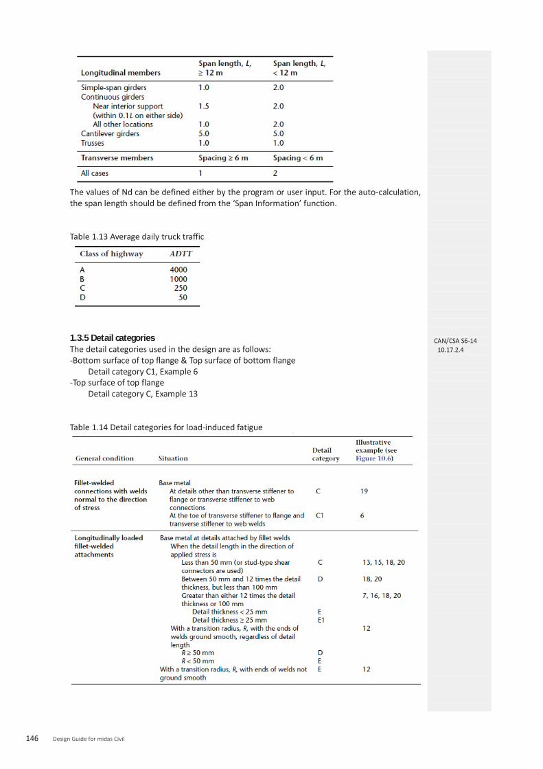
146 Design Guide for midas Civil
The values of Nd can be defined either by the program or user input. For the auto-calculation, the span length should be defined from the ‘Span Information’ function. Table 1.13 Average daily truck traffic
1.3.5 Detail categories The detail categories used in the design are as follows: -Bottom surface of top flange & Top surface of bottom flange
Detail category C1, Example 6 -Top surface of top flange
Detail category C, Example 13 Table 1.14 Detail categories for load-induced fatigue
CAN/CSA S6-14 10.17.2.4

Chapter 3. Steel Composite Box Girder Design – CAN/CSA S6-14 147

148 Design Guide for midas Civil
2. Shear Connector 2.1. ULS
2.1.1 Shear connector resistance (1) General The ULS check of shear connectors is performed by checking if the number of shear connectors applied in each shear span exceeds the minimum number of shear connectors. The number of shear connectors applied in the shear span, Nuse, is calculated as follows:
where a shear span, L, is a segment between points of maximum and zero moment at the ULS and it should be entered by the user. p = pitch of shear connectors floor function rounds a number down to the nearest integer. Nsc = number of shear connectors in a row The minimum number of shear connectors in each shear span is calculated as follows:
P is determined as follows: (a) for positive moment:
(i) when the plastic neutral axis is in the concrete slab: ; and (ii) when the plastic neutral axis is in the steel section: ; and
(b) for negative moment: . (2) Stud connectors in cast-in-place deck slab The factored shear resistance, qr , of a headed stud shear connector with h/d ≥ 4 is taken as
where Fu = minimum tensile strength of the stud steel Asc = cross-sectional area of one stud shear connector The program checks if the spacing of shear connectors is not less than 4d, nor greater than 600 mm. (3) Stud connectors in full-depth precast panels This is not supported in the program. (4) Channel connectors in cast-in-place deck slab Channel connectors are not supported in the program. 2.1.2 Longitudinal shear The longitudinal shear check along potential shear planes is not supported.
2.2. FLS 2.2.1 Fatigue resistance of stud shear connectors Stud shear connectors are designed for the following stress range, τ rs :
where CL = 1.0 when W ≤ 625 kN = 0.20 + 500/W when W > 625 kN Vsc = range of design shear force at the section along the length of the beam where the fatigue resistance of the shear connectors is being evaluated. The shear connectors are proportioned
CAN/CSA S6-14 10.11.8.3.1
CAN/CSA S6-14 10.11.8.3.2
CAN/CSA S6-14 10.11.8.4
CAN/CSA S6-14 10.17.2.7

Chapter 3. Steel Composite Box Girder Design – CAN/CSA S6-14 149
for the sum of the factored shears due to bending and torsion. Q = first moment of area of the transformed section at the interface between the concrete slab and the steel section s = shear stud group spacing Asc = cross-sectional area of a shear stud n = number of shear studs in the group at the cross-section being evaluated It = moment of inertia of the transformed composite section about the axis of bending
= fatigue stress range resistance for Category D, as determined as follows:
Fatigue life constant, γ =
Fatigue life constant, γ’ = Fsrt = constant amplitude threshold stress range
where y = design life (equal to 75 years) Nd = number of design stress cycles experienced for each passage of the design truck, as specified in Table 1.14 ADTTf = single-lane average daily truck traffic, which is estimated as p (ADTT), where p is 1.0, 0.85, or 0.80 for the cases of one, two, or three or more lanes available to trucks, respectively, and ADTT shall be as specified in Table 1.13.
Table 1.14 Values of Nd
The values of Nd can be defined either by the program or user input. For the auto-calculation, the span length should be defined from the ‘Span Information’ function. When stud shear connectors are not provided in negative moment regions, additional connectors, Na in number, shall be provided at each location of contraflexure, where
This requirement is not considered in the program.

150 Design Guide for midas Civil
3. Constructibility of a Composite Box Girder3.1. ULS
3.1.1 Bending (1) Positive moment (Tub girder) - Class 1 & 2 sections - Width-to-thickness ratios of elements in compression
Top Flange
Web
dc = depth of compression portion of web in flexure, mm
- Factored moment resistanc, Mr
- Laterally supported members The factored moment resistance, Mr is calculated based on the equation below.
The tensile resistance of the bottom flange is reduced to Rv Fy and it is assumed that the whole width of tension flange is effective.
- Laterally unbraced members For a section subjected to bending about its major axis and laterally unbraced over a length, L, the factored moment resistance, Mr, is calculated as
The critical elastic moment, Mu, of a monosymmetric section is taken as
where
where Mmax = maximum absolute value of factored bending moment in unbraced segment Ma = factored bending moment at one-quarter point of unbraced segment Mb = factored bending moment at midpoint of unbraced segment Mc = factored bending moment at three-quarter point of unbraced segment
L = length of unbraced segment of beam, mm
where βx= coefficient of monosymmetry
CAN/CSA S6-14 10.10.2.1 10.9.2
CAN/CSA S6-14 12.5.1.1 10.10.2.2
CAN/CSA S6-14 10.10.2.3

Chapter 3. Steel Composite Box Girder Design – CAN/CSA S6-14 151
For doubly symmetric sections, βx= 0.0 B1 = 0.0
so that
The general expression for the critical elastic moment and formulas for β x, J, and Cw for open-top box girder as specified in Clause C10.10.2.3 of CSA S6.1 are used.
where
, positive when S on compression side of C Iyy : minor axis moment of inertia of the cross-section
- Bending about the minor axis For a section subjected to bending about its minor axis, whether laterally braced or unbraced, the factored moment resistance, Mr, is calculated as
CAN/CSA S6.1-14 10.10.2.3
CAN/CSA S6-14 10.10.2.4

152 Design Guide for midas Civil
- Class 3 sections - Width-to-thickness ratio of elements in compression
Top Flange
Web
dc = depth of compression portion of web in flexure, mm
- Factored moment resistanc, Mr
Laterally supported members When continuous lateral support is provided to the compression flange of a member subject to bending about its major axis, the factored moment resistance, Mr, is calculated as
The tensile resistance of the bottom flange is reduced to Rv Fy and it is assumed that the whole width of tension flange is effective.
Laterally unbraced members For a section subjected to bending about its major axis and laterally unbraced over a length, L, the factored moment resistance, Mr , is calculated as
where The critical elastic moment, Mu, of doubly symmetric and monosymmetric sections is taken as
where
where Mmax = maximum absolute value of factored bending moment in unbraced segment Ma = factored bending moment at one-quarter point of unbraced segment Mb = factored bending moment at midpoint of unbraced segment Mc = factored bending moment at three-quarter point of unbraced segment
L = length of unbraced segment of beam
where βx= coefficient of monosymmetry
For doubly symmetric sections,
βx= 0.0 B1 = 0.0
so that
CAN/CSA S6-14 10.10.3.1 10.9.2
CAN/CSA S6-14 10.10.3.2
CAN/CSA S6-14 10.10.3.3

Chapter 3. Steel Composite Box Girder Design – CAN/CSA S6-14 153
The general expression for the critical elastic moment and formulas for β x, J, and Cw for open-top box girder as specified in Clause C10.10.2.3 of CSA S6.1 are used.
- Class 4 sections For beams and girders with continuous lateral support provided to the compression flange, with webs that meet the requirements of Class 3, and whose flanges exceed the slenderness limits of Class 3, the factored moment resistances is computed as for a Class 3 section, except that the elastic section modulus, S, is replaced by an effective section modulus, Se, determined using (a) an effective flange width of , for flanges supported along two edges; and (b) an effective projecting flange width of , for flanges supported along one edge. However, the projecting flange width shall not exceed 30t. - Bending about the minor axis For a section subjected to bending about its minor axis, whether laterally braced or unbraced, the factored resistance, Mr, shall be calculated as
- Stiffened plate girders - Width-to-thickness ratio of flanges The program checks if stiffened plate girders have Class 1, 2, or 3 flanges. - Width-to-thickness ratios of webs The width-to-thickness ratio of a transversely stiffened web, h/w, without longitudinal stiffeners, shall not exceed . If this requirement is not satisfied, the section is not valid. Therefore, the moment resistance check is skipped. The following provision of CAN/CSA S6-14 is not supported in the program. “In determining a width-to-thickness ratio, Fy may be replaced by the maximum compressive stress due to the factored ULS loads if the maximum shear at the FLS does not exceed Vr calculated in accordance with Clause 10.10.5.1, taking Ft = 0 and φs = 1.0.” When a longitudinal stiffener is provided, the width-to-thickness ratio, h/w, shall not exceed
. If this requirement is not satisfied, the section is not valid. Therefore, the moment resistance check is skipped. - Moment resistance The moment resistance, Mr is calculated in the same way as Class 3 sections. If longitudinal stiffeners are not provided and , the moment resistance, calculated for the compression flange, is reduced by the following factor.
(2) Negative moment (Tub girder) - Class 1, 2 & 3 sections - Width-to-thickness ratios of elements in compression
Bottom Flange
CAN/CSA S6.1-14 10.10.2.3
CAN/CSA S6-14 10.10.3.4
CAN/CSA S6-14 10.10.3.5
CAN/CSA S6-14 10.10.4.1
CAN/CSA S6-14 10.10.4.1 10.17.2.5
CAN/CSA S6-14 10.10.4.3
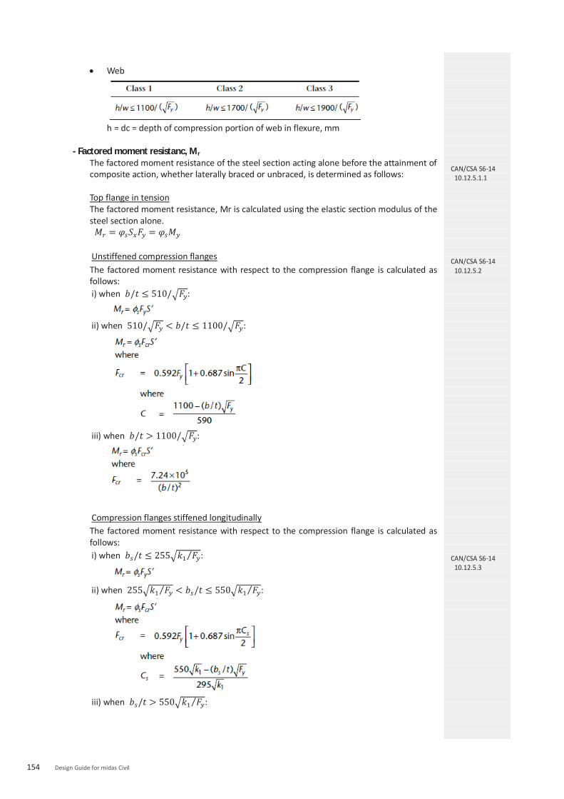
154 Design Guide for midas Civil
Web
h = dc = depth of compression portion of web in flexure, mm
- Factored moment resistanc, Mr
The factored moment resistance of the steel section acting alone before the attainment of composite action, whether laterally braced or unbraced, is determined as follows: Top flange in tension The factored moment resistance, Mr is calculated using the elastic section modulus of the steel section alone. Unstiffened compression flanges The factored moment resistance with respect to the compression flange is calculated as follows: i) when :
ii) when :
iii) when :
Compression flanges stiffened longitudinally The factored moment resistance with respect to the compression flange is calculated as follows: i) when :
ii) when :
iii) when :
CAN/CSA S6-14 10.12.5.1.1
CAN/CSA S6-14 10.12.5.2
CAN/CSA S6-14 10.12.5.3
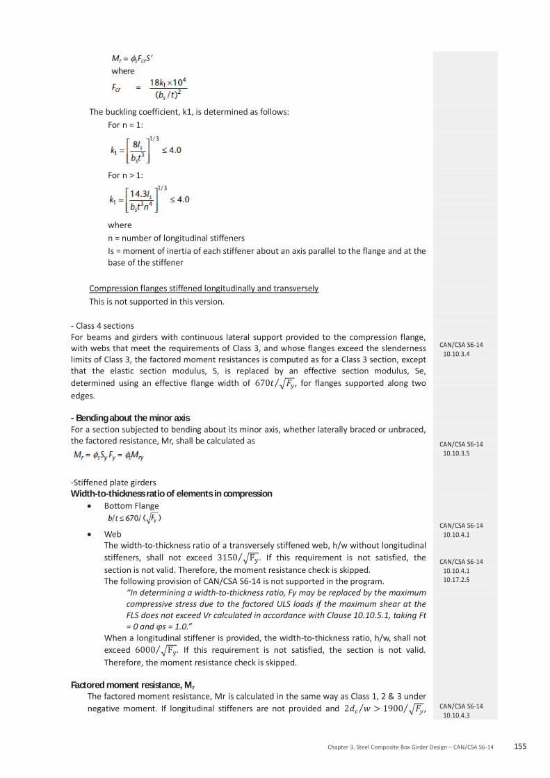
Chapter 3. Steel Composite Box Girder Design – CAN/CSA S6-14 155
The buckling coefficient, k1, is determined as follows:
For n = 1:
For n > 1:
where n = number of longitudinal stiffeners Is = moment of inertia of each stiffener about an axis parallel to the flange and at the base of the stiffener
Compression flanges stiffened longitudinally and transversely This is not supported in this version.
- Class 4 sections For beams and girders with continuous lateral support provided to the compression flange, with webs that meet the requirements of Class 3, and whose flanges exceed the slenderness limits of Class 3, the factored moment resistances is computed as for a Class 3 section, except that the elastic section modulus, S, is replaced by an effective section modulus, Se, determined using an effective flange width of , for flanges supported along two edges. - Bending about the minor axis For a section subjected to bending about its minor axis, whether laterally braced or unbraced, the factored resistance, Mr, shall be calculated as
-Stiffened plate girders Width-to-thickness ratio of elements in compression
Bottom Flange
Web
The width-to-thickness ratio of a transversely stiffened web, h/w without longitudinal stiffeners, shall not exceed . If this requirement is not satisfied, the section is not valid. Therefore, the moment resistance check is skipped. The following provision of CAN/CSA S6-14 is not supported in the program.
“In determining a width-to-thickness ratio, Fy may be replaced by the maximum compressive stress due to the factored ULS loads if the maximum shear at the FLS does not exceed Vr calculated in accordance with Clause 10.10.5.1, taking Ft = 0 and φs = 1.0.”
When a longitudinal stiffener is provided, the width-to-thickness ratio, h/w, shall not exceed . If this requirement is not satisfied, the section is not valid. Therefore, the moment resistance check is skipped.
Factored moment resistance, Mr The factored moment resistance, Mr is calculated in the same way as Class 1, 2 & 3 under negative moment. If longitudinal stiffeners are not provided and ,
CAN/CSA S6-14 10.10.3.4
CAN/CSA S6-14 10.10.3.5
CAN/CSA S6-14 10.10.4.1
CAN/CSA S6-14 10.10.4.1 10.17.2.5
CAN/CSA S6-14 10.10.4.3

156 Design Guide for midas Civil
the factored moment resistance, calculated for the compression flange, is reduced by the following factor.
3.1.2 Shear (1) Factored shear resistance The factored shear resistance of the web of a flexural member, Vr , is taken as
where Aw, the shear area, is calculated using d for rolled shapes and h for fabricated or manufactured girders, and Fs , the ultimate shear stress, is equal to Fcr + Ft , where Fcr and Ft are taken as follows:
For unstiffened webs, a/h is considered infinite, so that kv = 5.34. At girder end panels and adjacent to large openings in the web, the resistance shall be calculated using Ft = 0. However, there is no consideration about the end panels and openings in the web in the program. (2) Combined shear and moment When subject to the simultaneous action of shear and moment, transversely stiffened webs that depend on tension field action to carry shear, i.e., with , are proportioned so that
CAN/CSA S6-14 10.10.5.1
CAN/CSA S6-14 10.10.5.2

Chapter 3. Steel Composite Box Girder Design – CAN/CSA S6-14 157
(3) Intermediate transverse stiffeners The distance between stiffeners, a, shall not exceed when h/w is greater than 150 and shall not exceed 3h when h/w is less than or equal to 150. Intermediate transverse stiffeners provided on one or both sides of the web are proportioned so that
I is taken about an axis at the mid-plane of the web for stiffener pairs or at the near face of the web for single stiffeners.
Vf / Vr = the ratio at the end of element
D = 1.0 for stiffeners provided in pairs = 2.4 for single-plate stiffeners Single-angle stiffeners are not supported.
The width of a plate used as a stiffener shall not be less than 50 mm plus h/30 and shall not be less than one-quarter of the full width of the flange. The width-to-thickness ratio of intermediate transverse stiffeners shall not exceed . The projecting stiffener width shall not exceed 30t. (4) Longitudinal web stiffeners The spacing, a, of transverse stiffeners of longitudinally stiffened webs shall not exceed 1.5hp , where hp is the maximum subpanel depth. The total web depth, h, is used in determining the shear capacity, Vr, of longitudinally stiffened girders. Longitudinal stiffeners shall be proportioned so that (a) the stiffener width-to-thickness ratio does not exceed ; (b) the projecting stiffener width is less than or equal to 30t;
where I and r are calculated about a centroidal axis parallel to the web for a section comprising the stiffener or stiffeners and a strip of web 10w wide on each side. Additional requirements of transverse stiffeners for longitudinally stiffened webs are not checked by the program. (5) Bearing stiffeners Bearing stiffener check is not supported in the program.
CAN/CSA S6-14 10.10.6.1
CAN/CSA S6-14 10.10.6.2
CAN/CSA S6-14 10.10.7.1
CAN/CSA S6-14 10.10.7.2

158 Design Guide for midas Civil
4. Horizontally curved box girders 4.1 Composite box girder
4.1.1 Torsional constant of tub girder before composite section The torsional constant of a tub girder before the concrete slab is activated is somewhere between open section and closed section. Top flanges of tub section are restrained by the top lateral bracing system. The behaviour of a tub girder before the concrete deck has cured may be analyzed as a quasi-closed section by replacing the lateral bracing with an equivalent plate. In this version, the quasi-closed section method is not supported. The torsional constant is calculated based on closed section using the thickness of top flange. It is recommended that the user adjust the torsional constant using Stiffness Scale Factor. 4.1.2 Top flanges Top flanges shall be Class 3 or better. Flanges are proportioned to satisfy the following requirements: (a) Strength of either flange:
where Mfx = factored bending moment due to flexure Mrx = φsFy Sx
where Sx = elastic section modulus of the girder about its major axis
Mfw = factored bending moment in the flange due to torsional warping. Mfw is taken as regardless of the intermediate lateral restraint.
Where L = the distance between lateral restraintswr = the lateral load on the flange is a distributed lateral load, wr = Mfx/hR. Mfx = the moment in the vertical plane on the girder h = the clear depth of web between flanges R = the radius of curvature of the girder web (user input)
Mry = φsFy Sy where Sy = elastic section modulus of the flanges only about an axis in the plane tangent to the web of the girder
(b) Stability of compression flange:
where
where
wc = 0.5 where the lateral bending moment in the flange has major reversals, but 1.0 where the lateral bending moment does not have major reversals
CAN/CSA S6-14 10.13.7.1
CAN/CSA S6-14 10.13.7.3 10.13.6.1.2
CAN/CSA S6-14

Chapter 3. Steel Composite Box Girder Design – CAN/CSA S6-14 159
4.1.3 Bottom flanges (a) Tension flanges The factored moment resistance with respect to the tension flange is determined using a reduced normal stress, Rv Fy , in place of Fy , with Rv as follows:
It is assumed that total width is effective. (b) Stiffened compression flanges The following requirements shall apply to stiffened compression flanges:
When the torsional shear stress When , the factored moment resistance, Mr, is taken as
When and , the factored moment resistance,
Mr, is taken as
where k1 = the buckling coefficient, which shall not exceed 4.0 and, when at least one longitudinal stiffener is provided,
where
10.13.7.4.1
CAN/CSA S6-14 10.13.7.4.2.1

160 Design Guide for midas Civil
Is = moment of inertia of stiffener (c) Unstiffened compression flanges The requirements of stiffened compression flange apply to unstiffened compression flanges, except that the following values apply:
k1 = 4; ks = 5.34; and bs = b = width of flange between webs.
4.1.4 Webs The factored shear resistance is calculated in accordance with the provision for straight girders. The following requirements are also applied: (a) Webs without stiffeners: Tension-field action is neglected in webs without transverse
stiffeners. (b) Webs with transverse stiffeners only:
(i) Tension-field action is included in the calculated resistance when the geometry satisfies all of the following: (1) web slenderness h/w ≤ 160; (2) ratio of braced length to radius of horizontal curvature of the girder, Lb/R ≤ 0.1; and (3) transverse stiffener spacing a/h ≤ 3.
(ii) When subject to the simultaneous action of shear and moment, transversely stiffened webs that depend on tension-field action to carry shear is proportioned so that
(c) Webs with transverse and longitudinal stiffeners: When the longitudinal stiffeners are provided at a distance 0.2h from the compression flange, the program checks the web slenderness ratio satisfies the following condition.
When longitudinal stiffeners are located 0.2h from both the compression flange and the tension flange, the program checks if the web slenderness ratio does not exceed . Tension-field action is neglected. (d) Proportioning of transverse web stiffeners: the program checks if stiffeners are proportioned so that
CAN/CSA S6-14 10.13.7.4.2.2
CAN/CSA S6-14 10.13.6.1.3

Chapter 3. Steel Composite Box Girder Design – CAN/CSA S6-14 161
I is taken about an axis at the mid-plane of the web for stiffener pairs, or at the near face of the web for single stiffeners. Where transversely stiffened webs depend on tension-field action to carry the applied shear, the program also checks if the transverse stiffeners are proportioned so that.
Vf / Vr = the ratio at the end of element
D = 1.0 for stiffeners provided in pairs = 2.4 for single-plate stiffeners Single-angle stiffeners are not supported.
The width of a plate used as a stiffener shall not be less than 50 mm plus h/30 and shall not be less than one-quarter of the full width of the flange. The width-to-thickness ratio of intermediate transverse stiffeners shall not exceed . The projecting stiffener width shall not exceed 30t. (e) The program checks if longitudinal stiffeners are proportioned so that
(a) the stiffener width-to-thickness ratio does not exceed ; (b) the projecting stiffener width is less than or equal to 30t;
where I and r are calculated about a centroidal axis parallel to the web for a section comprising the stiffener or stiffeners and a strip of web 10w wide on each side.
(f) Monosymmetric sections: the program does not check if the slenderness ratio of the compression portion of webs of monosymmetric sections with an axis of symmetry in the plane of loading does not exceed one-half of the applicable value specified in Item (a), (b), or (c). This should be separately checked by the user.

162 Design Guide for midas Civil
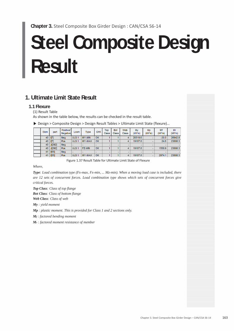
Chapter 3. Steel Composite Box Girder Design : CAN/CSA S6-14
Steel Composite Design Result
163Chapter 3. Steel Composite Box Girder Design – CAN/CSA S6-14
1. Ultimate Limit State Result 1.1 Flexure
(1) Result Table As shown in the table below, the results can be checked in the result table.
Design > Composite Design > Design Result Tables > Ultimate Limit State (flexure)…
Figure 1.37 Result Table for Ultimate Limit State of Flexure
Where,
Type: Load combination type (Fx-max, Fx-min, ... Mz-min). When a moving load case is included, there are 12 sets of concurrent forces. Load combination type shows which sets of concurrent forces givecritical forces.
Top Class: Class of top flange Bot Class: Class of bottom flange Web Class: Class of web
My : yield moment
Mp : plastic moment. This is provided for Class 1 and 2 sections only.
Mf : factored bending moment
Mr : factored moment resistance of member

164 Design Guide for midas Civil
(2) Excel Report The results can be viewed in an Excel Report as shown below.
Figure 1.38 Excel Report for Ultimate Limit State of Negative Moment
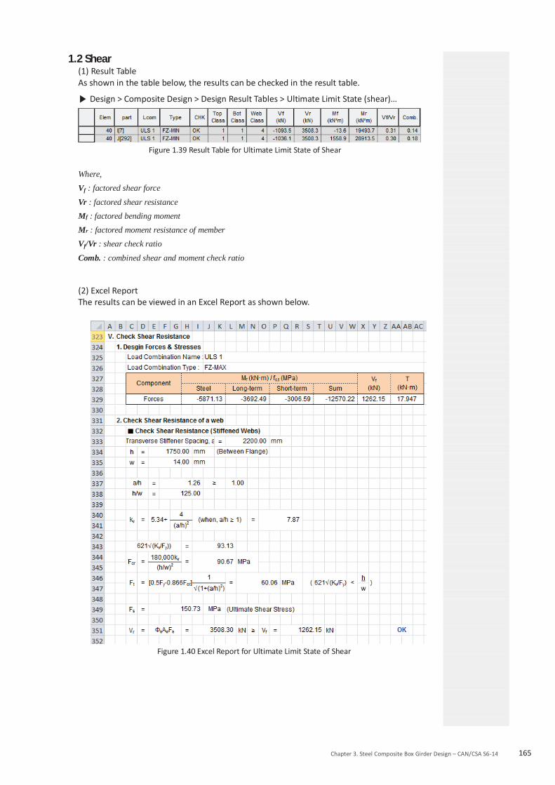
Chapter 3. Steel Composite Box Girder Design – CAN/CSA S6-14 165
1.2 Shear (1) Result Table As shown in the table below, the results can be checked in the result table.
Design > Composite Design > Design Result Tables > Ultimate Limit State (shear)…
Figure 1.39 Result Table for Ultimate Limit State of Shear
Where,
Vf : factored shear force
Vr : factored shear resistance
Mf : factored bending moment
Mr : factored moment resistance of member
Vf/Vr : shear check ratio
Comb. : combined shear and moment check ratio
(2) Excel Report The results can be viewed in an Excel Report as shown below.
Figure 1.40 Excel Report for Ultimate Limit State of Shear

166 Design Guide for midas Civil
2. Service Limit State Result (1) Result Table
The results can be viewed in an Excel Report as shown below.
Design > Composite Design > Design Result Tables > Service Limit State…
Figure 1.41 Result Table for Service Limit State Where,
Stress 0.90Fy : limit stress in the flange of the steel section to control permanent deflections Md : bending moment at SLS due to dead load, steel section only S : elastic section modulus of steel section Msd : bending moment at SLS due to superimposed dead load, composite section S3n : elastic modulus of section comprising the steel beam and the concrete slab, calculated using amodular ratio of 3n, long-term load, positive moment ML : bending moment at SLS due to live load, composite section Sn : elastic modulus of section comprising the steel beam and the concrete slab, calculated using amodular ratio of n, short-term load, positive moment S’ : elastic modulus of composite section comprising the steel section and reinforcement, negative moment
(2) Excel Report
The results can be viewed in an Excel Report as shown below.
Figure 1.42 Excel Report for Serviceability Limit State

Chapter 3. Steel Composite Box Girder Design – CAN/CSA S6-14 167
3. Constructibility Result 3.1 Flexure
(1) Result Table The results can be viewed in a result table as shown below.
Design > Composite Design > Design Result Tables > Construction Stage (flexure)...
Figure 1.43 Result Table for Constructibility Limit State of flexure
Where,
Mfy : factored bending moment about the y-axis of the cross-section Mry : factored moment resistance about the y-axis of the cross-section Mfz : factored bending moment about the z-axis of the cross-section Mrz : factored moment resistance about the z-axis of the cross-section Comb.1 : strength check ratio of flange for the combined moments Comb.2 : stability check ratio of compression flange for the combined moments (2) Excel Report The results can be viewed in an Excel Report as shown below.
Figure 1.44 Excel Report for Constructibility of Negative Moment

168 Design Guide for midas Civil
3.2 Shear (1) Result Table The results can be viewed in a result table as shown below.
Design > Composite Design > Design Result Tables > Construction Stage (shear)...
Figure 1.45 Result Table for Constructibility of Shear
Where,
Vf : factored shear force
Vr : factored shear resistance
Mf : factored bending moment
Mr : factored moment resistance of member
Vf/Vr : shear check ratio
Mf/Mr : moment check ratio
Comb. : combined shear and moment check ratio
(2) Excel Report The results can be viewed in an Excel Report as shown below.
Figure 1.46 Excel Report for Constructibility of Shear

Chapter 3. Steel Composite Box Girder Design – CAN/CSA S6-14 169
4. Fatigue Limit State Result (1) Result Table The results can be viewed in a result table as shown below.
Design > Composite Design > Design Result Tables > Fatigue Limit State...
Figure 1.47 Result Table for Fatigue Limit State
Where,
Lcom : Load combinations used in the calculation
fsr : calculated FLS stress range at the detail due to passage of the CL-W Truck
Fsr : fatigue stress range resistance
tau_rs: fatigue shear stress range for the stud shear connectors
Vsc : range of design shear force at the section along the length of the beam where the fatigueresistance of the shear connectors is being evaluated
(2) Excel Report The results can be viewed in an Excel Report as shown below.
Figure 1.48 Excel Report for Fatigue Limit State

170 Design Guide for midas Civil
5. Shear Connector Result (1) Result Table
The results can be viewed in a result table as shown below.
Design > Composite Design > Design Result Tables > Shear Connector...
Figure 1.49 Result Table for Shear Connector
Where,
h/d : height to diameter ratio of shear connector
qr : factored shear resistance of shear connectors
N : number of shear connectors entered in shear span
Nreq : required number of shear connectors in shear span
(2) Excel Report
The results can be viewed in an Excel Report as shown below.
Figure 1.50 Excel Report for Shear Connector

Chapter 3. Steel Composite Box Girder Design – CAN/CSA S6-14 171
6. Stiffener Result (1) Result Table
The results can be viewed in a result table as shown below.
Design > Composite Design > Design Result Tables > Transverse Stiffener...
Figure 1.51 Result Table for Stiffener
Where, h/w : ratio of clear depth of web to web thickness h/w_lim : 150, Web stiffeners are not required when the unstiffened shear resistance exceeds the factored shear and h/w ≤ 150. a : stiffener spacing a_lim : limit of stiffener spacing as per clause 10.10.6.1 As : area of stiffener or pair of stiffeners It : moment of inertia of transverse stiffener It_lim : limit of moment of inertia of transverse stiffener as per clause 10.10.6.2 w/t : width-to-thickness ratio of intermediate transverse stiffeners 200/sqrt(Fy) : limit of width-to-thickness ratio of intermediate transverse stiffeners as per clause10.10.6.2 wp : projecting stiffener width 30t : limit of projecting stiffener width as per clause 10.10.6.2
(2) Excel Report
The results can be viewed in an Excel Report as shown below.
Figure 1.52 Excel Report for Stiffener

172 Design Guide for midas Civil
7. Total Checking
(1) Result Table
Design > Composite Design > Design Result Table...
Summary results for each member can be viewed in a result table as shown below.
Figure 1.53 Result Table for Toal Checking

CAN/CSA S6-14for midas CivilDESIGN GUIDE


![INTERAZIONE TERRENO STRUTTURA GTS NX Interoperabilità ......Interoperabilità completa di MIDAS GTS NX con MIDAS GEN/CIVIL e MIDAS FEA . 2 ... [MIDAS/Gen] Design Query Tools V ew](https://img.dokumen.tips/doc/110x75/5ea9d82b430290276b378860/interazione-terreno-struttura-gts-nx-interoperabilit-interoperabilit.jpg)


![MIDAS Civil vs RM_[Www.vnc-group.com]](https://img.dokumen.tips/doc/110x75/55cf98e4550346d0339a475f/midas-civil-vs-rmwwwvnc-groupcom.jpg)