Embed Size (px)
Citation preview

IMPLEMENTATION GUIDE No.1
Open Graded AsphaltDesign Guide
1997
•• •
MPA

Cover Photographs:
Open graded asphalt in action! The top photograph shows typicalvehicle spray on a conventional surfacing in wet weather, the bottomphotograph (taken shortly afterwards on an adjacent section of thesame road) clearly shows the spray reducing qualities of open gradedasphalt.
COPYRIGHT © Australian Asphalt Pavement Association 1997(reprinted 2000)
AAPA Implementation Guide IG-1
ACKNOWLEDGEMENTS
This document was prepared by a working group consisting ofpersonnel from ARRB Transport Research, AUSTROADS and asphaltindustry representatives from funding provided by the AustralianAsphalt Pavement Association. Information from a Master ofEngineering thesis by 1. Skvarka undertaken at Royal MelbourneInstitute of Technology was used in the formulation of the designmethod. Drafts have been widely circulated within the asphaltindustry for assessment and comment.
Members of the editorial committee comprised:
Allan Alderson, ARRB TR
John Bethune, AAPA
John Oliver, ARRB TR
John Rebbechi, CSR Emoleum
Reproduction of extracts from this publication may be madesubject to due acknowledgment of the source.
Although the information in this Guide is believed to be correct atthe time ofprinting, the Australian Asphalt Pavement Associationdoes not accept any contractual, tortious or other form of liabilityfor its contents or for any consequences arising from its use.People using the information contained in this Guide shouldapply, and rely upon, their own skills and judgement to theparticular issue which they are considering.
Open Graded AsphaltDesign Guide
1997
australianasphalt~ntassodal1on

Open Graded Asphalt
PREFACEThis gUide has been prepared to supplement the Australian Provisional Guidefor the Selection and Design of Asphalt Mixes by gUiding users through theselection, design and application process for Open-Graded Asphalt mixes.
The Guide is directed at inexperienced mix designers as well as experienceddesigners who are unfamiliar with the new Australian Provisional Design Methodand is intended to be informative rather than mandatory. Additional referencemay be reqUired to relevant Australian Standards or public authority manualsand specifications.
2
Open Graded Asphalt
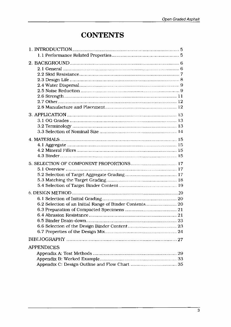
CONTENTS
1. INTRODUCTION 51.1 Performance Related Properties 5
2. BACKGROUND 62.1 General 62.2 Skid Resistance 72.3 Design Life 82.4 Water Dispersal 92.5 Noise Reduction 92.6 Strength 112.7 Other 122.8 Manufacture and Placement 12
3. APPLICATION 133.1 OG Grades 133.2 Terminology 133.3 Selection of Nominal Size 14
4. MATERIALS 154.1 Aggregate 154.2 Mineral Fillers.......................................................................... 154.3 Binder 15
5. SELECTION OF COMPONENT PROPORTIONS 175.1 Overview 175.2 Selection of Target Aggregate Grading 175.3 Matching the Target Grading 185.4 Selection of Target Binder Content 19
6. DESIGN METHOD 206.1 Selection of Initial Grading 206.2 Selection of an Initial Range of Binder Contents 206.3 Preparation of Compacted Specimens 216.4 Abrasion Resistance 216.5 Binder Drain-down 236.6 Selection of the Design Binder Content 236.7 Properties of the Design Mix 24
BIBLIOGRAPHY 27
APPENDICESAppendix A: Test Methods 29Appendix B: Worked Example 33Appendix C: Design Outline and Flow Chart 35
3

Open Graded Asphalt
4
Open Graded Asphalt
1. INTRODUCTIONThere is an ever increasing requirement by Road Authorities to use Open-GradedAsphalt as the surfacing on heavily trafficked pavements for environmental andsafety reasons. The purpose of this gUide is to promote a rational procedure forthe design of Open-Graded Asphalt (OG) mixes used as a wearing course on roadpavements. Until now the selection and design of these mixes has been basedessentially on a recipe type approach which users with little or no experiencefound difficult to interpret and implement.
The rational procedure described herein is intended to improve the performanceof OG mixes, particularly design life, by introducing performance related testmethods. The test methods selected are based upon current Australian practiceand the findings of overseas workers using equipment that is commonlyavailable in asphalt laboratories.
1.1 Performance Related Properties
The term 'performance related' indicates that the properties used in the mixselection and design process are those which determine its on-road performance.Thus, if good test results for a mix are obtained in the laboratory there isconfidence that the material will perform satisfactorily on the road.
The design of OG mixes in the past has focussed on attaining a grading andbinder content that gave a range of air void contents. While the provision of aporous structure is crucial to the performance of this type of mix, there are othercriteria that also need to be addressed in order for the mix to fulfil its functionover the design life.
5

Open Graded Asphalt
2. BACKGROUND
2.1 General
Open-Graded Asphalt (OG) has been in use as a wearing surface since the1950s. Its first major use in Australia was about 1973 and it is known under awide range of names in different parts of the world, such as:
• Open-graded asphalt
• Porous friction mix
• Open-textured asphalt
• Friction course
• Drainage asphalt
• Whisper asphalt
• Porous asphalt
• Pervious macadam.
The use of terminology involving reference to 'friction' is to be discouraged sincethe frictional resistance of any asphalt mix is dependent on the aggregate qualitymuch more than the type of mix.
OG is a mix with a high air void content (in excess of 20%) that is used generallyin thin layers (typically 25 to 40 mm). While it provides a small increase inpavement strength it is not suitable for regulating a deformed surface or in highshear situations. Its main use is in urban areas, particularly on arterial typeroads, where it provides:
• enhanced wet weather skid resistance,
• reduced vehicle rolling noise, both external to, and within the vehicle,
• reduced surface water spray,
• improved visibility of road surface markings, particularly in wet weather, and
• a smooth riding surface.
OG is a gap graded mix with intermediate sized and fine aggregate fractionsomitted from the grading while dense-graded asphalt has a more continuousgrading. Air voids are more inter-connected in OG compared to dense-gradedmixes where the voids are often occluded. This is shown diagrammatically in Fig2.1.
6

Dense graded Open graded
Open Graded Asphalt
Stone Mastic
Fig. 2.1 Schematic of Aggregate Skeletons for Various Mix Types
2.2 Skid Resistance
The skid resistance of OG mixes in wet conditions is markedly better than adense-graded asphalt surfacing. The potential for aquaplaning is much reducedat normal driving speeds and, together with improved visibility, due to areduction in water spray, may be the most important benefit for using this typeof mix. Water is dispersed into the voids thus eliminating the wedge of waterthat develops in front of tyres moving across films of water. Use of OG increasesdriver confidence when driving during wet weather and this effectively increasesthe road capacity although the increase in speed may offset some of the safetybenefit.
In dry conditions OG has a lower skid resistance than traditional surfacings asthere is less stone in contact with the tyre. However. the selection of anaggregate suitable for a wearing course will provide adequate skid resistancewhen dry.
When first placed, OG may have an initially lower skid resistance than expecteddue to the thicker film of binder coating the exposed aggregates. Traffic action,however, should remove this coating within one or two weeks, but the processmay take up to several months depending on traffic and environmentalconditions. Extra precautions may be needed when placing OG on low-volumehigh-speed roads at the beginning of the cold season. In critical situations thesurface of the fresh asphalt may be "dusted" with a carborundum grit.
Skid resistance is measured in a number of ways, the simplest of which is to usea pendulum style tester (see Fig 2.2). There are a number of specificallydesigned vehicles that can continuously measure skid resistance.
7

Open Graded Asphalt
Fig. 2.2
2.3 Design Life
Testing the Skid Resistance of an Asphalt Surfaceusing a Pendulum Style Tester
The major concern when selecting an OG has been the limited life (about 8 to 10years for normal binders and 12 to 15 years for PMBs) compared to a densegraded asphalt surfacing. OG layers often fail due to lack of durability. usuallyindicated by surface fretting and ravelling.
The porous nature of OG mixes exposes the binder-film coating the aggregates tothe actions of ultra-violet light, oxidation and moisture. It is critical that thebinder-film has sufficient thickness to resist these effects and that resistantbinders (eg PMBs) are used when extended life is sought.
If design life is redefined as the retention of surface characteristics. rather thanstructural integrity. then the design life of OG is generally greater than mostother surfacings.
2.4 Water Dispersal
The life of a pavement surfaced with an OG wearing course can be prolonged byensuring that surface water is drained off the pavement such that it does notcause damage to underlying layers or present a safety problem due to sheet flowover the surface. To achieve this it is essential that the underlying surface beimpervious. that there is sufficient crossfall and that ~ide drainage isprovided.
8

Open Graded Asphalt
Dense graded asphalt can not be considered impervious unless it has an in-situair void content less than 5%. Trafficking of dense-graded asphalt can assist increating an impervious surface by reducing the in-situ air void content belowthat which existed at construction. Dense-graded asphalts with higher air voidsare considered to be permeable. and hence may have a reduced service life ifplaced below an OG. If trafficking of dense-graded asphalt prior to placing theOG is not possible, then application of a very heavy tack coat. a fog-coat or a 7mm seal to the surface of the dense-graded asphalt, prior to placing the OGlayer, can provide sufficient waterproofing. The use of stone mastic asphalt(SMA) directly below an OG is another way of achieving an imperviousunderlying layer.
There are a number of alternative arrangements for draining water from an OGand several are shown in Fig. 2.3. A common practice is to provide a freedraining edge as in Figs. 2.3a and 2.3b although these can pose a hazard forcyclists. The arrangement shown in Fig. 2.3c applies to new constructionwhereas those shown in Figs 2.3a and 2.3b can be applied as overlays to existingpavements. There has also been some experimentation with pavements that areporous in more than the top layer (see Fig. 2.3c) but a discussion of these isbeyond the scope of this guide.
softshoulder
Old pavement
/
/
4 em
slow lane
shoulder
hard shoulderI·
Kerb
Channel(0 few em)
i---lI I
: p..'--III
Porous as hall
Porous asptKJlt
Fig.2.3a
2%-Asphalt concrete
Asphalt concrete
Lean concrete base
Drain
Cementconcrete
CD porous asphalt (e.g. 4 em thick)
CD impervious underlying layer
Sand cement
Fig 2.3 bSub-Base
Fig.2.3c
Fig 2.3 Alternative Arrangements for Draining an OG
9

Open Graded Asphalt
In some countries OG layers are designed to ameliorate the effects of short highintensity rainfall by acting as a retarding reservoir. In this application. the OGlayer is designed to retard peak flows by storing water within the layer andreleasing it gradually.
The porosity of OG reduces over time by clogging of the pores with road grime.although it is more often evident in shoulders and between wheel paths. Intrafficked areas it has been found that high speed traffic cleans the pores tosome extent and thus maintains a high porosity layer. If, however. the pores areblocked and water can not flow from the edge of the layer it will flow over thesurface. reducing most of the benefits of using OG. There have been someinstances of authorities moving traffic lanes laterally so that traffic is directedover clogged sections of the pavement to help cleanse the layer.
Slippage failure as well as shoving can occur in OG when subject to severebraking and acceleration. In addition. stripping of the cohesive bond betweenthe binder and the aggregate can result from fuel and oil spillages and leaksfrom vehicles. For these reasons OG is not recommended at intersections.Typical practice requires that an OG layer is terminated 50 to 100 metres fromthe approach side of an intersection. It is essential to ensure a smooth jointbetween the different mixes and care should be taken to avoid trapping water atthe joint. Similarly OG is not recommended in areas where vehicles will betracking mud and other detritus on to the road such as in areas with quarryingor farming activities.
2.5 Noise Reduction
Another significant benefit of OG is the reduction in noise levels. A reduction of3 dB(A) is often quoted as the difference in noise level between a dense-gradedand OG surfacing. This is eqUivalent to a reduction in noise levels of about half.or a doubling of the distance from the noise source. The reduction can be evengreater on wet surfaces where reduction in noise from water spray is particularlynoticeable inside vehicles.
The reduction in noise level is proportional to the accessible air voids whichappears to reach an optimum where 14 mm OG is used with a layer thickness of35 mm to 40 mm. For cost and other factors a nominal thickness of 30 mm of 10mm OG is frequently placed.
The reduction in noise is partly achieved by a reduction in the amount ofcompressed air escaping between the tyre and the pavement surface. Both stonemastic and OG surfaces consist of voids below a plane surface. In addition. forOG mixes. some air is expelled into the pores. There is a further reduction dueto the surface texture which reduces the reflected noise, although as the surfaceaggregate wears, reduction due to surface texture diminishes.
In 1989. noise levels were monitored on a number of road surface types(Samuels. 1990) and the results are presented in Table 2.1. It can be seen that awide range of noise levels were encountered and OG was found to be the quietestsurfacing. with a reduction of 4 dB(A) to 6 dB(A) compared to dense-gradedasphalt. Two OG mixes are presented in Table 2.1 (the numbers in bracketsrepresent the years in which the mixes were designed) and it can be seen thatthe later designed mix (more porous than the 1975 OG mix) gave a greater noise
10

Open Graded Asphalt
reduction. There will be an increase in the noise levels with time. but OG willstill generate lower noise levels than other surfacing types.
Measurement of noise in Australia is performed to AS 2704 and involves settingup measuring equipment a distance back from the edge of the pavement andrecording noise levels of passing vehicles (see Fig. 2.4). Adjustment factors areapplied to compensate for a number of variables, including the distance betweenthe instrument and the vehicle where more than one lane is to be monitored.
Table 2.1 - L10(lh) Noise Levels Monitored over a Rangeof Pavement Surfaces
Pavement Surface Type L10(lh) (dB(A))
Portland Cement Concrete - Deep Grooved 87.2
Portland Cement Concrete - Shallow Grooved 83.8
Dense-Graded Asphalt 83.4
Cold Overlay Slurry Seal 82.6
Portland Cement Concrete - Hessian Dragged 80.8
Open-Graded Asphalt (1975) 79.3
Open-Graded Asphalt (1987) 77.5
'III
/"
•
II::.7\". -.1\ "",-
Fig. 2.4 Instruments Arranged for Way-side Measurements
11

Open Graded Asphalt
2.6 Strength
In the past, the OG layer has often been disregarded in calculating thestructural strength of a pavement. In part, the decision was based on thestrength being about one half to two thirds that of dense-graded asphalt, and inpart due to it being laid in thin layers. Present practice, however, is to adopt amodulus value of between 800 MPa and 1200 MPa. Despite this reassessmentof its strength, OG will not improve the deflection characteristics of an unsoundpavement.
If testing of OG in the laboratory is to be undertaken to detennine performancecharacteristics it is well to remember that specimens need to be confined. Testssuch as the (unconfined) dynamic creep test do not give an accurate indicationof mix properties and, should the rutting performance of the mix be reqUired, itis recommended that the Wheel Tracking test be employed. In general, OG hasvery good deformation resistance provided it is placed on a sound underlyingpavement. Fatigue testing of OG can be undertaken using the four point bendingbeam test at low temperatures. In general, fatigue life is inversely related to thevoid content, so that, typically, OG provides about three quarters the fatigue lifeof a dense-graded asphalt. A further characteristic of OG asphalt is the ability ofminor cracks to self heal due to the high bitumen film thicknesses andreorientation of course aggregate particles.
2.7 Other
The dark open surface provides a greater contrast with pavement markings andreduces reflected light thus giving drivers more confidence.
2.8 Manufacture and Placement
Manufacture of an OG mix is similar in most respects to a dense-graded mix,although mixing temperatures are generally lower by 10D C to 20D C to minimisethe risk of binder drain-down. Drain-down can also be experienced dUringtransportation to site but good work practices will substantially eliminate thisrisk. The mix design method proposed in this gUide will also assist in reducingdrain-down to acceptable levels.
Construction of an OG layer utilises the same eqUipment as for a dense-gradedmix but there are differences in the compaction techniques to ensure a suitablefinal prodUct. Due to reduced layer thickness and higher air void content, careneeds to be exercised to ensure that rollers follow closely behind the paver tocompact the mix whilst hot. It is preferable to use steel rollers operating in thenon-vibratory mode and to limit the number of passes so that crushing of theaggregate or closure of the air voids is avoided. Rubber-tyred rollers andvibrating steel rollers are not used because the mix has a tendency to stick tothe wheels of the former, and the kneading and vibratory effects of the latter canforce the binder to the surface, closing up the surface voids. Vibrating rollerscan also cause crushing of aggregates due to the high proportion of point topoint contacts developed in the mix.
Joints need special attention, to ensure continuity of the drainage paths. Tackcoating of the edge of pervious cool OG blocks the drainage paths. Hotlongitudinal joints are preferable. Hand work should be minimised, or preferablyaVOided, as it is difficult to achieve porosity or good finishes.
12

Open Graded Asphalt
3. APPLICATION
3.1 OG Grades
ExpeIience in Australia suggests that two grades of OG are sufficient for theanticipated range of applications and these gradings are designated as Type Iand Type II. Suggested cIiteIia for the selection of the type to be used are shownin Table 3.1.
Table 3.1 - OG Grade Selection Criteria
Open-Graded Asphalt Indicative Traffic VolumeType
Commercial Vehicles / EqUivalent Standardlane / day Axles*
Type I < 500 < 5 X 10⁶
Type II > 500 > 5 X 10⁶
*
Type I
Type II
Based on a pavement design life of 30 years.
OG intended to give a modest level of performance where theextended life obtainable with higher binder contents and modifiedbinders is not considered justified.
OG intended to give premium performance through the use ofhigher binder contents and/or modified binders. Fibres can beadded to such mixes to reduce drain-down at the higher bindercontents. Design procedures descIibed in this gUide areparticularly applicable to optimising the performance of suchmixes.
3.2 Terminology
The descIiption of OG uses a format consistent with that used in the 'Selectionand Design of Asphalt MLxes: Australian Provisional Guide' and is shown below:
Mix Type
Nominal Size
Grade
Binder type or class
Additional suffix (if required)
IOG 14 11170 R
13
Open Graded Asphalt
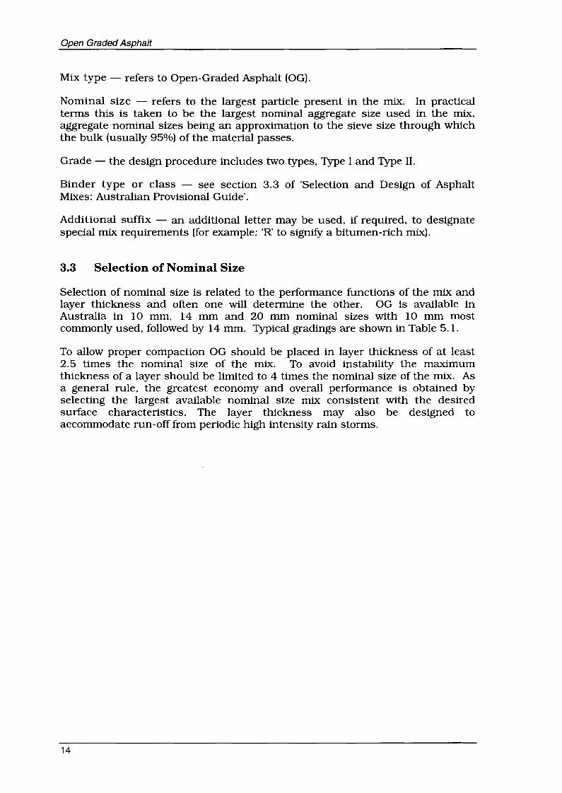
Mix type - refers to Open-Graded Asphalt (OG).
Nominal size - refers to the largest particle present in the mix. In practicalterms this is taken to be the largest nominal aggregate size used in the mix,aggregate nominal sizes being an approximation to the sieve size through whichthe bulk (usually 95%) of the material passes.
Grade - the design procedure includes two types, Type I and Type II.
Binder type or class - see section 3.3 of 'Selection and Design of AsphaltMixes: Australian Provisional Guide'.
Additional suffix - an additional letter may be used, if required. to designatespecial mix requirements (for example: 'R' to signify a bitumen-rich mix).
3.3 Selection of Nominal Size
Selection of nominal size is related to the performance functions of the mix andlayer thickness and often one will determine the other. OG is available inAustralia in 10 mm, 14 mm and 20 mm nominal sizes with 10 mm mostcommonly used, followed by 14 mm. Typical gradings are shown in Table 5.1.
To allow proper compaction OG should be placed in layer thickness of at least2.5 times the nominal size of the mix. To avoid instability the maximumthickness of a layer should be limited to 4 times the nominal size of the mix. Asa general rule, the greatest economy and overall performance is obtained byselecting the largest available nominal size mix consistent with the desiredsurface characteristics. The layer thickness may also be designed toaccommodate run-off from periodic high intensity rain storms.
14

Open Graded Asphalt
4. MATERIALS
4.1 Aggregate
OG comprises 94-97% by mass of aggregate and due to the high level ofmechanical interlock of the aggregate skeleton, reqUires high quality aggregate toensure that vehicle loads can be distributed to underlying layers. The aggregateneeds to be strong, clean, durable, cubical. have good micro-texture, possess ahigh proportion of crushed faces and have an affinity for bitumen.
Aggregates conforming to wearing course specifications will usually meet thesereqUirements.
A more detailed discussion on aggregates is given in 'Selection and Design ofAsphalt Mixes: Australian Provisional Guide'.
4.2 Mineral Fillers
Mineral fillers are defined as that part of the aggregate in a mix that is finer than0.075 mm. They are derived from the coarse and fine aggregate componentsand/or from recycling the dust extracted from the crushing and screening plantsor from asphalt plants but can also be added materials such as hydrated lime.Portland cement, ground slag. ground limestone or fly-ash. The addition ofhydrated lime mineral filler also reduces binder drain-down.
A more detailed discussion on mineral fillers is given in 'Selection and Design ofAsphalt Mixes: Australian Provisional Guide'.
Lack of durability and ravelling in OG layers is often due to binder oxidation orlow binder contents. It can also be due to loss of adhesjon between binder andaggregate, generally known as stripping. Mineral fillers can be chosen toimprove binder/aggregate adhesion and hence. reduce the potential forstripping.
In this regard, the strongly preferred mineral filler is hydrated lime. but Portlandcement and ground limestone may also be used.
4.3 Binder
The role of the binder is to provide sufficient cohesion for the mix to resistsurface fretting and ravelling. Durability is important and the binder should beeither resistant to oxidation or be present as a sufficiently thick coating on theaggregate particles so that oxidation hardening leading to cracking and loss ofcohesion is postponed until the design life is achieved.
A more detailed discussion on binders is given in 'Sdection and Design ofAsphalt Mixes: Australian Provisional Guide'.
Use of excessive binder contents is detrimental to the proper functioning of themix. It will reduce air void contents, and possibly lead to excessive binder draindown dUring transport.
15

Open Graded Asphalt
Modified binders can be used to improve OG properties through improvedcohesion and durability. They may also assist in reducing binder drain-down.Modified binders, such as styrene-butadiene-styrene (SBS), styrene-butadienerubber (SBR), ethylene-vinyl-acetate (EVA), crumbed rubber modified (CRM) andmultigrade binders have all been used with success.
All of the above mentioned polymer modified binders have shown an improvedretention of the binder within the mix when compared to conventional bitumensprovided that the benefit is not negated by the use of higher mix temperatures.The skinning effect on the surface of polymer modified binder tends to assist thecleansing of the air voids under the action of traffic.
Fibres (0.3 to 0.5% by mass) are very effective in preventing binder drain-downand helping retain the binder on the aggregate but have little influence on otherproperties of OG.
16
Open Graded Asphalt
5. SELECTION OF COMPONENT PROPORTIONS
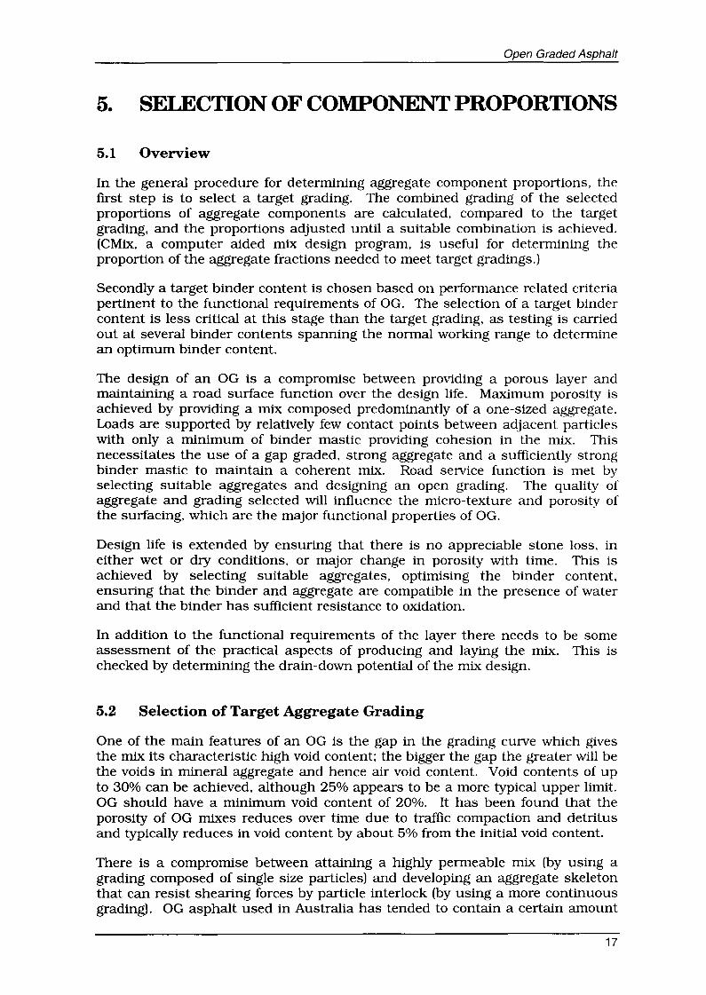
5.1 Overview
In the general procedure for detennining aggregate component proportions, thefirst step is to select a target grading. The combined grading of the selectedproportions of aggregate components are calculated, compared to the targetgrading, and the proportions adjusted until a suitable combination is achieved.(CMix, a computer aided mix design program, is useful for determining theproportion of the aggregate fractions needed to meet target gradings.)
Secondly a target binder content is chosen based on performance related criteriapertinent to the functional reqUirements of OG. The selection of a target bindercontent is less critical at this stage than the target grading, as testing is carriedout at several binder contents spanning the normal working range to determinean optimum binder content.
The design of an OG is a compromise between providing a porous layer andmaintaining a road surface function over the design life. Maximum porosity isachieved by providing a mix composed predominantly of a one-sized aggregate.Loads are supported by relatively few contact points between adjacent particleswith only a minimum of binder mastic providing cohesion in the mix. Thisnecessitates the use of a gap graded, strong aggregate and a sufficiently strongbinder mastic to maintain a coherent mix. Road service function is met byselecting suitable aggregates and designing an open grading. The quality ofaggregate and grading selected will influence the micro-texture and porosity ofthe surfacing, which are the major functional properties of OG.
Design life is extended by ensuring that there is no appreciable stone loss, ineither wet or dry conditions, or major change in porosity with time. This isachieved by selecting suitable aggregates, optimising the binder content,ensuring that the binder and aggregate are compatible in the presence of waterand that the binder has sufficient resistance to oxidation.
In addition to the functional requirements of the layer there needs to be someassessment of the practical aspects of producing and laying the mix. This ischecked by determining the drain-down potential of the mix design.
5.2 Selection of Target Aggregate Grading
One of the main features of an OG is the gap in the grading curve which givesthe mix its characteristic high void content; the bigger the gap the greater will bethe voids in mineral aggregate and hence air void content. Void contents of upto 30% can be achieved, although 25% appears to be a more typical upper limit.OG should have a minimum void content of 20%. It has been found that theporosity of OG mixes reduces over time due to traffic compaction and detritusand typically reduces in void content by about 5% from the initial void content.
There is a compromise between attaining a highly permeable mix (by using agrading composed of single size particles) and developing an aggregate skeletonthat can resist shearing forces by particle interlock (by using a more continuousgrading). OG asphalt used in Australia has tended to contain a certain amount
17

Open Graded Asphalt
of fmes to enhance mechanical stability and reduce risk of binder drainage. Useof recommendations in this gUide are likely to result in coarser mixes to providegreater porosity while providing other measures to control risk of binder draindown.
The target gradings shown in Table 5.1 can be used as an initial starting point inthe absence of other data. These may need to be adapted to cater for specificaggregates or specific circumstances. The suggested gradings tend to be coarserthan the design grading envelopes in 'AS 2150 - Hot Mix Asphalt' and manyState Road Authority specifications but will result in a more porous mix.
Table 5.1 - Typical Centre-Line Target Gradings for OG (Percent Passing)
Sieve Aperture Nominal Mix Size
(mm) 10mm 14mm 20mm ProductionTolerance
26.5 100 Nil
19.0 100 95 +6
13.2 100 95 55 +6
9.5 90 50 30 +6
6.7 40 27 20 +6
4.75 20 11 10 +5
2.36 12 9 8 +5
1.18 8 8 6 +5
0.6 6 6.5 4 +5
0.3 5 5.5 3 +3
0.15 4 4.5 3 +3
0.075 3.5 3.5 2 + 1
5.3 Matching the Target Grading
The target grading must be matched using the individual aggregate components(or stockpiles) available. The basic formula for combining aggregate is:
P = Aa + Bb + Cc. etc.
where
At B t C etc. =
a, b, c etc. =
=P the percentage of combined aggregate passing a given sieve
percentages of material passing a given sieve for each of thegiven aggregates A, B, C, etc.
proportion of aggregates A, B, C, etc, used in thecombination and where the total is 1.0.
The procedure is facilitated by using a computer spreadsheet package or CMix.The final combined grading is designated as the 'job mix'.
18
Open Graded Asphalt
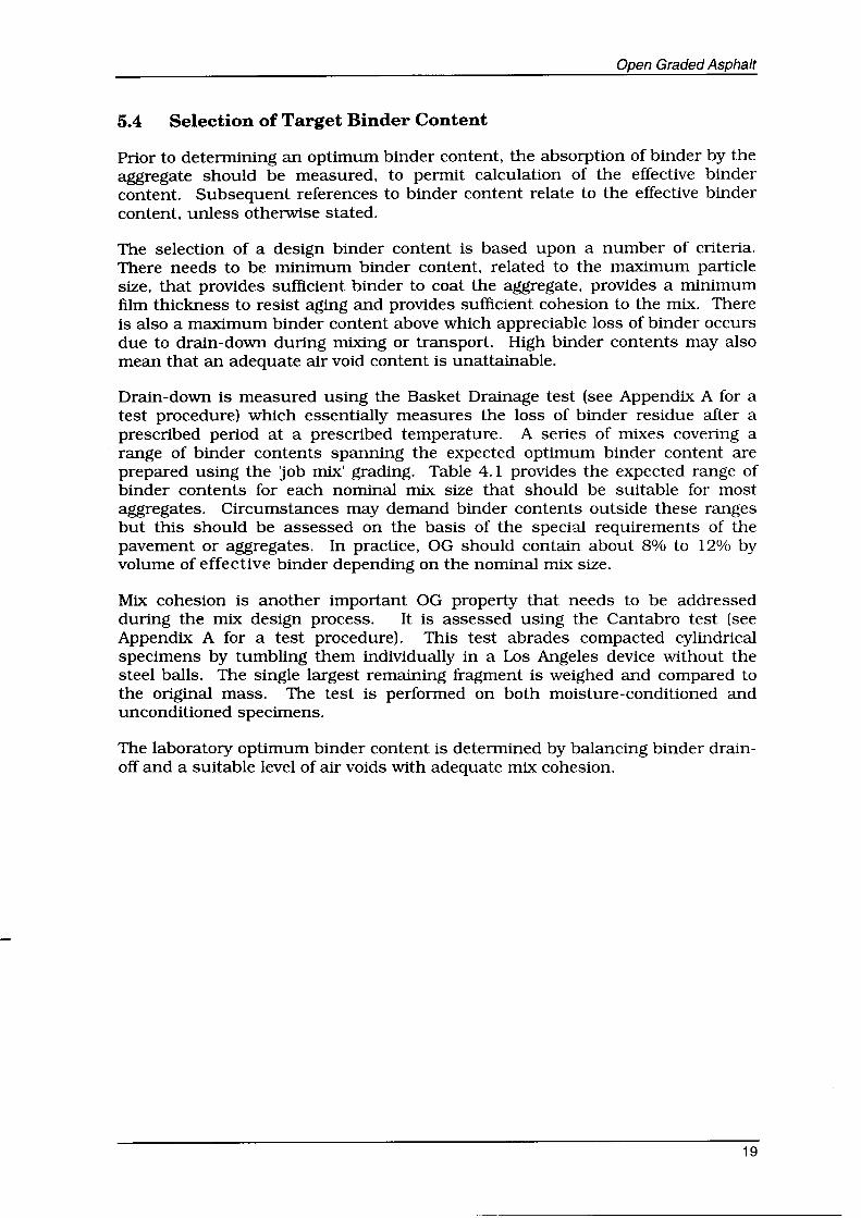
5.4 Selection of Target Binder Content
Prior to detennining an optimum binder content. the absorption of binder by theaggregate should be measured. to pennit calculation of the effective bindercontent. Subsequent references to binder content relate to the effective bindercontent. unless otherwise stated.
The selection of a design binder content is based upon a number of criteria.There needs to be minimum binder content. related to the maximum particlesize. that provides sufficient binder to coat the aggregate. provides a minimumfilm thickness to resist aging and provides sufficient cohesion to the mix. Thereis also a maximum binder content above which appreciable loss of binder occursdue to drain-down dUring mixing or transport. High binder contents may alsomean that an adequate air void content is unattainable.
Drain-down is measured using the Basket Drainage test (see Appendix A for atest procedure) which essentially measures the loss of binder residue after aprescribed period at a prescribed temperature. A series of mixes covering arange of binder contents spanning the expected optimum binder content areprepared using the 'job mix' grading. Table 4.1 provides the expected range ofbinder contents for each nominal mix size that should be suitable for mostaggregates. Circumstances may demand binder contents outside these rangesbut this should be assessed on the basis of the special requirements of thepavement or aggregates. In practice. OG should contain about 8% to 12% byvolume of effective binder depending on the nominal mix size.
Mix cohesion is another important OG property that needs to be addresseddUring the mix design process. It is assessed using the Cantabro test (seeAppendix A for a test procedure). This test abrades compacted cylindricalspecimens by tumbling them individually in a Los Angeles device without thesteel balls. The single largest remaining fragment is weighed and compared tothe original mass. The test is performed on both moisture-conditioned andunconditioned specimens.
The laboratory optimum binder content is determined by balancing binder drainoff and a suitable level of air voids with adequate mix cohesion.
19
Open Graded Asphalt
6. DESIGN METHOD
6.1 Selection of Initial Grading
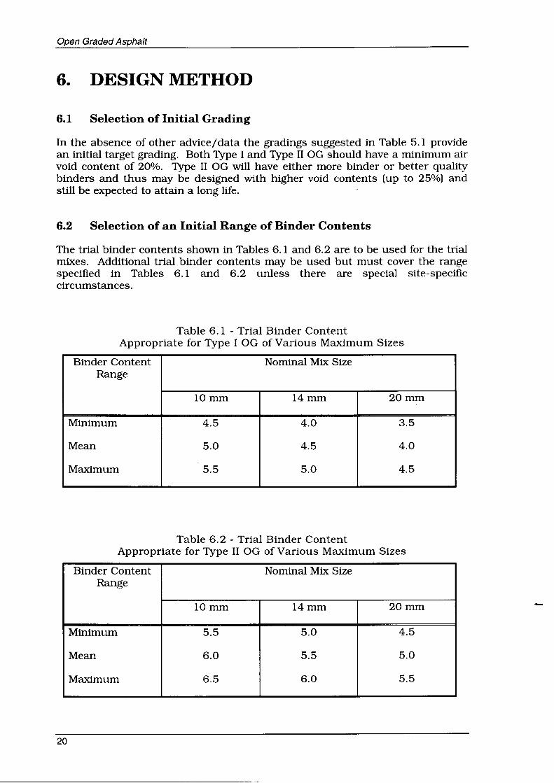
In the absence of other advice/data the gradings suggested in Table 5.1 providean initial target grading. Both Type I and Type II OG should have a minimum airvoid content of 20%. Type II OG will have either more binder or better qualitybinders and thus may be designed with higher void contents (up to 25%) andstill be expected to attain a long life.
6.2 Selection of an Initial Range of Binder Contents
The trial binder contents shown in Tables 6.1 and 6.2 are to be used for the trialmixes. Additional trial binder contents may be used but must cover the rangespecified in Tables 6.1 and 6.2 unless there are special site-specificcircumstances.
Table 6.1 - Trial Binder ContentAppropriate for Type I OG of Various Maximum Sizes
Binder Content Nominal Mix SizeRange
10mm 14mm 20mm
Minimum 4.5 4.0 3.5
Mean 5.0 4.5 4.0
Maximum 5.5 5.0 4.5
Table 6.2 - Trial Binder ContentAppropriate for Type II OG of Various Maximum Sizes
Binder Content Nominal Mix SizeRange
10mm 14mm 20mm
Minimum 5.5 5.0 4.5
Mean 6.0 5.5 5.0
Maximum 6.5 6.0 5.5
20
Open Graded Asphalt
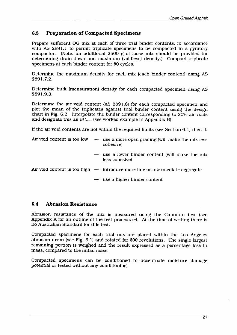
6.3 Preparation of Compacted Specimens
Prepare sufficient OG mix at each of three trial binder contents. in accordancewith AS 2891.1 to pennit triplicate specimens to be compacted in a gyratorycompactor. (Note: an additional 2500 g of loose mix should be provided fordetennining drain-down and maximum (voidless) density.) Compact triplicatespecimens at each binder content for 80 cycles.
Detennine the maximum density for each mix (each binder content) using AS2891.7.2.
Detennine bulk (mensuration) density for each compacted specimen using AS2891.9.3.
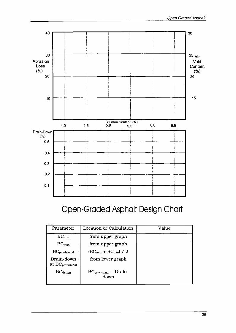
Detennine the air void content (AS 2891.8) for each compacted specimen andplot the mean of the triplicates against trial binder content using the designchart in Fig. 6.2. Interpolate the binder content corresponding to 20% air voidsand designate this as BCmax (see worked example in Appendix B).
If the air void contents are not within the reqUired limits (see Section 6.1) then if:
Air void content is too low
Air void content is too high
6.4 Abrasion Resistance
use a more open grading (will make the mix lesscohesive)
use a lower binder content (will make the mixless cohesive)
introduce more fine or intermediate aggregate
use a higher binder content
Abrasion resistance of the mix is measured using the Cantabro test (seeAppendix A for an outline of the test procedure). At the time of writing there isno Australian Standard for this test.
Compacted specimens for each trial mix are placed within the Los Angelesabrasion drum (see Fig. 6.1) and rotated for 300 revolutions. The single largestremaining portion is weighed and the result expressed as a percentage loss inmass, compared to the initial mass.
Compacted specimens can be conditioned to accentuate moisture damagepotential or tested without any conditioning.
21

Open Graded Asphalt
Shaft bearingmounted onconcrete piersor other rigid
_fjS:=s12±8~su~pports
Not less than 1270 mm measuredon outside of drum
__ --- '--J/' --...../
/' ......../ "-
/ ~
\\\\II
/
Cast steel or rolledsteel ends not lessthan 14 mm thick
510 mm ±2 mm
Catch pan fortest portion
III !---=...r-=-~....I
IIIIII
II Gasket II~ ~.!l 11
VIEW A VIEWS
Fig. 6.1 Los Angeles Abrasion Apparatus
The test is conducted on unconditioned specimens in triplicate. within 7 days ofmanufacture. The mean Cantabro abrasion loss for each triplicate group isplo.tted against trial binder content.
The binder content corresponding to the maximum Cantabro abrasion lossappropriate to the mix is interpolated and designated as BCmin.
The recommended mean maximum loss permitted for unconditioned samples is20% for Type II OG and 25% for Type I OG.
The mix must be rejected if any individual specimen has more than 50%Cantabro abrasion loss.
If the mean Cantabro abrasion loss is greater than the desired limit then:
increase the binder content (decrease air void content)
include more intermediate sized aggregates (decrease air voidcontent).
use a binder with improved cohesive properties.
22

Open Graded Asphalt
6.5 Binder Drain-down
Determine the drain-down at each trial binder content using the BasketDrainage test procedure. There should be no more than 0.3% drain-down.
Plot the drain-down against trial binder content so that the drain-down at theprovisional binder content (see section 6.7) can be interpolated. If the draindown is greater than 0.3% then:
use fibres (typically 0.3% by mass of total aggregate mass).
decrease the binder content (increase air void content)
use a binder with improved cohesive properties (for example PMBs).
use a mineral filler complying with the recommendations given insection 4.2 or increase the mineral filler content (decrease the airvoid content).
6.6 Selection of the Design Binder Content
A design chart such as that shown in Fig. 6.2 can be used to select themaximum and minimum binder contents that fulfil the design air void contentand abrasion requirements. The minimum air void content limit (20%) will setthe maximum binder content (Bcmax) . The maximum Cantabro abrasion loss(25% for Type I and 20% for Type II) will set the minimum binder content(BCmin) .
The provisional binder content is the mean of BCmax and BCmin. The draindown is linearly interpolated at the provisional binder content. If the estimateddrain-down is less than 0.3% then the mix is deemed to be suitable and thedesign binder content is then found by adding the estimated drain-down to theprovisional binder content. (See Appendix B for a worked example.) If theestimated drain-down is greater than 0.3% then the mix will need to beredesigned. see section 6.5.
If the calculated design binder content is less than the appropriate rrummumvalue in either Tables 6.1 or 6.2 then the minimum binder content from theTables shall be adopted as the provisional binder content. The design bindercontent shall then be the minimum binder content from the Tables plus thedrain-down at the provisional binder content.
If BCmln is greater than BCmax then the mix needs to be redesigned. If 20% airvoid content is not encompassed in the trial mixes then the grading should bealtered.
The design binder content can be altered to accommodate peculiarities of amix, ie. an increase in the binder content may be required to improve theCantabro abrasion loss values, this is permitted provided that drain-down orair void content values do not fall outside the recommended limits.
23

Open Graded Asphalt
6.7 Properties of the Design Mix
Having detennined a design binder content, it is necessary to detennine theproperties of the design mix. Manufacture sufficient mix to compact 6specimens at the provisional binder content with an additional 2500 g of loosemix for drain-down and maximum density testing. (Note: it is assumed that littledrain-down will occur in the laboratory or that the OG will be briefly re-mixed tohomogeneous composition prior to compaction.)
Compact six specimens using the same procedure as previously. All specimensare tested to detennine air void content. Three unconditioned specimens aretested to detennine the Cantabro abrasion loss as previously described andthree are conditioned using the procedure outlined in Appendix A. Theconditioned specimens have a binder viscosity approximating one year in serviceand are tested to detennine the Cantabro abrasion losses which should be lessthan 35% for Type I and less than 30% for Type II mixes. If the mix does notsatisfy these limits then the mix needs to be modified, see section 6.4 and thebullet points listed below;
• Increase binder content (within the acceptable range),
• Incorporate mineral filler complying with the recommendations given insection 4.2,
• Select a more cohesive binder (usually PMB), and
• Select a more compatible binder/aggregate combination.
If the mix at the provisional binder content meets all stipulated reqUirements. itis satisfactory and can be manufactured and placed at the design bindercontent.
Table 6.3 - Summary of Design Limits
Design Criteria Type II Type I
Cantabro Abrasion Loss < 20 < 25- Unconditioned (%)
Cantabro Abrasion Loss < 30 < 35- Conditioned (%)
Air void Content (%) 20 - 25 > 20
Drain Off (%) < 0.3
24
40
30
AbrasionLoss(%)
20
Open Graded Asphalt
r---,......---r----.....,.---.....,..----,----..,..---, 30
25 AirVoid
Content(%)
20
10 1-~+-~~~-+-~~~-+~~~~~~~---I-~~~-\-----1 15
4.0 4.5Bitumen Content (%)5.0 5.5 6.0 6.5
Drain-Down(%)
0.5
0.4
0.3
0.2
0.1
i i ,
Iii
i,
I,, I i
! I i! I , i
i
iI
, ,
Ii i iI
, , ,
i iI I
II
II , i -+--~
i i ! ii, i ,I ,
!,
i!
iI II
I.
Open-Graded Asphalt Design Chart
Parameter Location or Calculation Value
BCmin from upper graph
BCmax from upper graph
BCprovistonal (BCmax + BCmin) / 2
Drain-down from lower graphat BCprovistonal
BCdestgn BCprovistonal + Drain-down
25

Open Graded Asphalt
26
Open Graded Asphalt
BIBLIOGRAPHY
COLONNA, P. (1993). Design and performance of porous asphalt in the Pugliaregion of southern Italy. Proceedings of the 5th Eurobitume Congress 1993.Stockholm - Volume IB, (Eurobitume).
CLIFFIRD, R.. DILLON, S., WALSH, G. & JAMIESON, I. (1993). Design andperformance of porous asphalt mixes in Ireland. Proceedings of the 5thEurobitume Congress 1993. Stockholm - Volume IB, (Eurobitume).
EUROSYMPOSIUM (1992). The mitigation of traffic noise in urban areas.Reference Book, 2nd Edition Nantes, France November 1992 (Eurosymposium.France).
HORAK., E. et al (1994). The use of porous asphalt on mqjor roads inJohannesburg. Proceedings of the 6th Conference on Asphalt Pavements forSouthern Africa. Vol 2. ppVI-65 to VI-81.
JIMENEZ. F.E.P. & PEREZ, M.A.C. (1990). Analysis and evaluation of theperformance of porous asphalt: The Spanish experience. Surface Characteristicsof Roadways. ASTM STP 1031 pp.512-527.
PIARC (1993). Porous asphalt. PlARC Technical Committee on SurfaceCharacteristics (PIARC, Paris).
REBBECHI, J.J. (1994). Fibre Modified Open Graded Asphalt. Proceedings ofthe 9th AAPA International Asphalt Conference, Australia. 1994 (AAPA).
SABITA (1995). Porous asphalt mixes - Design and use. Manual 17 (SABITA,South Africa).
SAMUELS, S. (1990). Australian road surface treatments to minimise tyre/roadnoise. Proceedings of International Tire/Road Conference. Sweden. 1990. Vol.1. pp.91-101.
SKVARKA, I.G.R. (1996). A rationale for the design of open graded frictioncourse asphalt. Masters of Engineering Thesis at the Royal Melbourne Instituteof Technology (RMIT, Melbourne).
STANDARDS AUSTRALIA (1995). Method ofSampling and Testing Aggregates.AS 1141 (Standards Association of Australia).
STANDARDS AUSTRALIA (1995). Hot Mix Asphalt. AS 2150 (StandardsAssociation of Australia).
STANDARDS AUSTRALIA (1995). Method ofSampling and Testing Asphalt. AS2891 (Standards Association of Australia).
TRANSPORf RESEARCH COUNCIL (1990).international perspective 1990. TRR 1265.Washington).
Porous Asphalt Pavements: An(Transportation Research Board,
27

Open Graded Asphalt
28
Open Graded Asphalt
APPENDIX A
TEST METHODS
CANTABRO TEST PROCEDURE
Scope:
This test is used to detennine the abrasion resistance of laboratory prepared.compacted asphalt specimens. Specimens can be tested with or withoutconditioning but must be tested within 7 days of manufacture. This method isbased upon testing nominally identical triplicate specimens.
Test Specimens:
Test specimens should have air voids contents as specified in Summary Table6.3.
The specimens should be compacted in a Gyropac such that the finished heightof the specimen is 65 ± 1 mm (for 100 mm diameter specimens) or 80 ± 1 mm(for 150 mm diameter specimens).
Apparatus:
Los Angeles Abrasion Loss Drum conforming to AS 1141.
Balance with a capacity of 5000 g capable of measuring to 0.1 g
Temperature controlled environment capable of maintaining a temperature of25 ± l QC
Water bath capable of maintaining 25 ± 1DC
Procedure:
1. Ensure that the first test specimen has been dried to constant mass andrecord this to the nearest 0.1 g as mIl'
2. Allow the specimen to attain a temperature of 25 ± 1QC.
3. Place the first specimen into the Los Angeles Abrasion Loss drum and rotatefor 300 revolutions (without the steel balls). The Los Angeles Abrasion Lossdrum should also be at 25 ± 5QC.
29

Open Graded Asphalt
4. Select the largest remaining fragment of asphalt from the drum anddetermine and record the mass as m 12 • Remove the remainder of the residue.
5. Repeat steps 1 to 4 for the two remaining specimens from the triplicate grouprecording the masses as m
21, m
22, m
3land m
32•
6. Where testing of specimens conditioned for the effect of moisture is to becarried out, place the specimens in the water bath at 25 ± 1DC for 20 to 24hours.
7. Remove the specimen from the water bath and blot dry the surface with adamp towel and record the mass to the nearest 0.1 g as mil"
8. Test moisture conditioned specimens in the same manner as steps 3 to 5,above.
Calculations:
The Cantabro abrasion loss (CAL) is calculated as follows:
For each specimen C~ = (mil -mi2 )/ X 100/mil
The mean of the triplicates is calculated as CAL =(CALI + CAL2 + CAL3)/3
Reporting of Results:
The air void content of each specimen is to be reported along with the specimenpreparation procedure. The individual Cantabro abrasion loss for each specimenis reported as well as the mean Cantabro abrasion loss for dry conditioned andmoisture conditioned specimens as appropriate. If the CAL for any specimen isgreater than 50% the test shall be repeated.
30
Open Graded Asphalt
BASKET DRAINAGE TEST
Scope:
This procedure is used to assess the amount of binder that is likely to draindown from a mix dUring transport to site. It is suitable for all fresh hot mixedasphalts.
This method is suitable for asphalt mixes that have a nominal maximum particlesize of 20 mm or less. For mixes with a nominal size greater than 20 mm agreater quantity of asphalt may be reqUired.
Apparatus:
Mechanical mixer of not more than 8 I capacity
Drainage baskets 100 ± 2 mm in all dimensions constructed from a perforatedsteel plate with 3.5 ± 0.5 mm diameter holes such that there is 44 ± 3 % openarea. Feet are to be fIxed to each corner that are 3 mm square in cross-sectionand 5 mm high.
Oven, capable of achieving 170 ± 5QC
Balance, with a capacity of 5000 g readable to 0.1 g
Timer. readable to the nearest second
Heat resistant gloves
Metal drip trays, 150 mm square and 10 mm deep.
Procedure:
1. Line a metal drip tray with aluminium foil, determine the mass and record asmI'
2. Weigh a clean, dry drainage basket and record the mass as m 2 .
3. Combine aggregate, binder and additional mix constituents according to AS2891.1
4. Remove a 1100 ± 50 g representative sample and place in drainage basket.Place the drainage basket on to the drip tray and determine the mass andrecord as m 3 .
5. Place drainage basket and drip tray into oven and condition the sample for187 ± 8 minutes according to the temperatures stipulated in AS 2891.1.
31

Open Graded Asphalt
6. Repeat steps 1 to 5 for a duplicate sample.
7. Remove the drainage basket and drip tray from the oven.
8. Remove the drainage basket and determine the mass of the drip tray andbinder residue. Record as m 4 .
Note: Care should be taken to minimise heat loss at all times.
Calculations:
The loss of binder is calculated as follows:
((m4 -m)) )
Percent Drain-down = ( _ _ ) x 100m, m2 ml
If the difference in the percent drain-down for duplicate tests is greater than0.5% then the test shall be repeated. The percent drain-down is the arithmeticmean of the duplicate measurements.
Reporting of Results:
Report the following:
• Mix preparation procedure
• Conditioning time and temperature in oven
• Percent drain-down of individual tests and the mean.
32

Open Graded Asphalt
APPENDIXB
WORKED EXAMPLE
The example below is for a 14 mm Type II Open-Graded Asphalt. The maximumbinder content permissible to achieve a minimum air void content of 20% is5.2%. The minimum binder content reqUired to ensure that there is less than20% Cantabro abrasion losses is 4.7%. Therefore the provisional binder contentis:
(5.2% + 4.7%) / 2 = 4.95%.
Then interpolating the drain-down at the provisional binder content it wasestimated that the drain-down would be 0.2%. This results in a design bindercontent of:
4.95% + 0.2% = 5.15%, say 5.2%.
33

Open Graded Asphalt
Parameter Location or Calculation Value
BCmin from upper graph 4.8%
BCmax from upper graph 5.2%
BCprovisional (BCmin + BCmax) / 2 5.0%
Drain-down at BCprovisional from lower graph 0.2%
BCdesign BC provisional + Drain-down 5.2%
Triplicate specimens were produced at the provisional binder content and themeans are plotted on the above figure. The mean Cantabro abrasion loss for theunconditioned specimens is shown by a diamond and the mean Cantabroabrasion loss for the conditioned specimens is shown by a triangle while the voidcontent is shown by a circle. It can be seen that both Cantabro abrasion lossvalues are below the permitted limits and the air void content is above 20% thusindicating a satisfactory mix.
34

Open Graded Asphalt
APPENDIXC
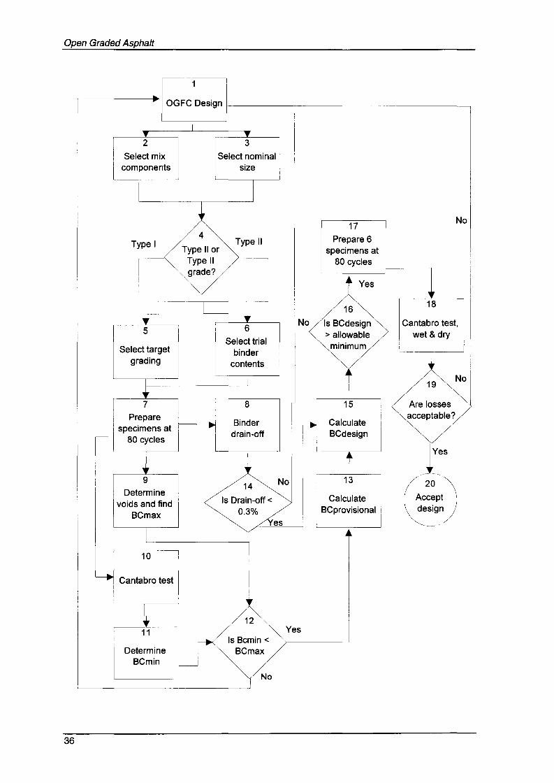
Design Outline and Flow Chart
Notes for the Design of Open-Graded Asphalt (OG)
1. Select mix components which can include: aggregate, binder, mineral fillerand other (eg cellulose fibres).
2. Components are selected against job specifications which address the mostsuitable nominal mix size (eg 10 mm, 14 mm, etc). Will depend on layerthickness and desired surface characteristics (and possibly water storagecapacity).
3. Need to decide if a Type I or Type II OG is required which will impact on thequality of the materials required and the cost of the mix.
4. A target grading is required and advice on these is given in section 5.2.
5. Select trial binder contents (minimum of three) which will depend upon thenominal mix size and Type of the OG (see sections 5A and 6.2).
6. Prepare sufficient mix for three specimens at each trial binder content andcompact for 80 gyratory cycles to AS 2891.2.2. Ensure an additional 2500g of loose mix is prepared.
7. Determine drain-down for each trial binder content and plot drain-downversus binder content (see design chart).
8. Determine the bulk density using method AS 2891.9.3, maximum (voidless)density using AS 2891.7.1 and volumetric properties using AS 2891.8. Plotair void content versus bitumen content (see design chart) and find BC maxat 20% air void content.
9. Test each compacted (unconditioned) specimen to determine Cantabroabrasion loss.
10. Plot Cantabro abrasion loss against binder content (see design chart) anddetermine BCmin at the appropriate level of loss which depends on the OGtype.
11. BCmin should be less than BCmax. If not, the mix will need to be redesigned.
12. BCprovisional is the mean of BCmax and BCmin.
13. The drain-down at the provisional binder content must be less than 0.3%.
14. BCdesign is BCprovisional plus the drain-down at that binder content.
15. Check that the design binder content is greater than the allowableminimum given in Tables 6.1 and 6.2.
16. Prepare 6 specimens at the provisional binder content for 80 cycles.
17. Condition three specimens and test in Cantabro test. Test the remainingthree specimens in the Cantabro test.
18. Calculate Cantabro abrasion losses and compare with acceptance criteriain Table 6.3. If not acceptable then the design will need to be altered.
19. Accept design iflosses are acceptable.
35
Open Graded Asphalt
OGFC Design I-----r-------------~
2
Select mixcomponents
3
I
Select .nominalsize
I__~_-----.J
Type I4
Type II orType IIgrade?
Type II
17Prepare 6
specimens at80 cycles
t Yes
No
5
Select targetgrading
6Select trial
bindercontents
16
No Is BCdesign> allowable
minimum
18
Cantabro test,wet & dry
19No
Binder
ldrain-off--
7Prepare
specimens at80 cycles
9
Determinevoids and find
BCmax
10
Cantabro test
8
14
Is Drain-off <0.3%
No
es
15
CalculateBCdesign
~13
CalculateBCprovisional
iI
Are lossesacceptable?
t s
/ 20 OJ'
( Acc~pt~deSlgn
36
1211 Yes
Is Bcmin <Determine BCmax
BCmin
No

•• •
MPA--_ •• aIL
AuslroIiaft Aspidl,~ Aucaahont...,I2, 5 ........gblSlrwt~ VIdOnO 3101 AlJSTRAlJA
1031 9853 35951031 9853 341MiI«4wpo.OJIl.ouwww.CIO:IpO ~.QII