Embed Size (px)
Citation preview

TSI SERIES 4000/4100 HIGH PERFORMANCE
LINEAR OEM MASS FLOWMETER (TSI MODELS 4021, 4024, 4121, AND 4122)
DESIGN GUIDE
1980430, REVISION K FEBRUARY 2016


SHIP/MAIL TO: TSI Incorporated 500 Cardigan Road Shoreview, MN 55126-3996 USA USA Sales and Customer Service: (800) 874-2811/(651) 490-2811 Fax: (651) 490-3824
E-mail address: [email protected]
Website: http://flowmeters.tsi.com
INTERNATIONAL
Sales and Customer Service: (+1) 651 490-2811
Fax: (+1) 651 490-3824
TSI SERIES 4000/4100 HIGH PERFORMANCE
LINEAR OEM MASS FLOWMETER (TSI MODELS 4021, 4024, 4121, AND 4122)
DESIGN GUIDE

iv

v
Copyright
TSI Incorporated / 2004-2016 / All rights reserved.
LIMITATION OF WARRANTY AND LIABILITY (effective February 2015)
Seller warrants the goods sold hereunder, excluding software, under normal use and service as described in the operator's manual, shall be free from defects in workmanship and material for 90 days for OEM components, from the date of shipment to the customer. This warranty period is inclusive of any statutory warranty. This limited warranty is subject to the following exclusions and exceptions:
a. Hot-wire or hot-film sensors used with research anemometers, and certain other components when indicated in specifications, are warranted for 90 days from the date of shipment.
b. Pumps are warranted for hours of operation as set forth in product or operator’s manuals.
c. Parts repaired or replaced as a result of repair services are warranted to be free from defects in workmanship and material, under normal use, for 90 days from the date of shipment.
d. Seller does not provide any warranty on finished goods manufactured by others or on any fuses, batteries or other consumable materials. Only the original manufacturer's warranty applies.
e. This warranty does not cover calibration requirements, and seller warrants only that the instrument or product is properly calibrated at the time of its manufacture. Instruments returned for calibration are not covered by this warranty;
f. This warranty is VOID if the instrument is opened by anyone other than a factory authorized service center with the one exception where requirements set forth in the manual allow an operator to replace consumables or perform recommended cleaning;
g. This warranty is VOID if the product has been misused, neglected, subjected to accidental or intentional damage, or is not properly installed, maintained, or cleaned according to the requirements of the manual. Unless specifically authorized in a separate writing by Seller, Seller makes no warranty with respect to, and shall have no liability in connection with, goods which are incorporated into other products or equipment, or which are modified by any person other than Seller.

vi
The foregoing is IN LIEU OF all other warranties and is subject to the LIMITATIONS stated herein. NO OTHER EXPRESS OR IMPLIED WARRANTY OF FITNESS FOR PARTICULAR PURPOSE OR MERCHANTABILITY IS MADE. WITH RESPECT TO SELLER’S BREACH OF THE IMPLIED WARRANTY AGAINST INFRINGEMENT, SAID WARRANTY IS LIMITED TO CLAIMS OF DIRECT INFRINGEMENT AND EXCLUDES CLAIMS OF CONTRIBUTORY OR INDUCED INFRINGEMENTS. BUYER’S EXCLUSIVE REMEDY SHALL BE THE RETURN OF THE PURCHASE PRICE DISCOUNTED FOR REASONABLE WEAR AND TEAR OR AT SELLER’S OPTION REPLACEMENT OF THE GOODS WITH NON-INFRINGING GOODS.
TO THE EXTENT PERMITTED BY LAW, THE EXCLUSIVE REMEDY OF THE USER OR BUYER, AND THE LIMIT OF SELLER'S LIABILITY FOR ANY AND ALL LOSSES, INJURIES, OR DAMAGES CONCERNING THE GOODS (INCLUDING CLAIMS BASED ON CONTRACT, NEGLIGENCE, TORT, STRICT LIABILITY OR OTHERWISE) SHALL BE THE RETURN OF GOODS TO SELLER AND THE REFUND OF THE PURCHASE PRICE, OR, AT THE OPTION OF SELLER, THE REPAIR OR REPLACEMENT OF THE GOODS. IN THE CASE OF SOFTWARE, SELLER WILL REPAIR OR REPLACE DEFECTIVE SOFTWARE OR IF UNABLE TO DO SO, WILL REFUND THE PURCHASE PRICE OF THE SOFTWARE. IN NO EVENT SHALL SELLER BE LIABLE FOR LOST PROFITS, BUSINESS INTERRUPTION, OR ANY SPECIAL, INDIRECT, CONSEQUENTIAL OR INCIDENTAL DAMAGES. SELLER SHALL NOT BE RESPONSIBLE FOR INSTALLATION, DISMANTLING OR REINSTALLATION COSTS OR CHARGES. No Action, regardless of form, may be brought against Seller more than 12 months after a cause of action has accrued. The goods returned under warranty to Seller's factory shall be at Buyer's risk of loss, and will be returned, if at all, at Seller's risk of loss.
Buyer and all users are deemed to have accepted this LIMITATION OF WARRANTY AND LIABILITY, which contains the complete and exclusive limited warranty of Seller. This LIMITATION OF WARRANTY AND LIABILITY may not be amended, modified or its terms waived, except by writing signed by an Officer of Seller.
Service Policy
Knowing that inoperative or defective instruments are as detrimental to TSI as they are to our customers, our service policy is designed to give prompt attention to any problems. If any mal-function is discovered, please contact your nearest sales office or representative, or call TSI at (800) 874-2811 (USA) and (1) 651 490-2811.

vii
CONTENTS
Chapter 1 - Models and Accessories .............................................. 1 Accessories .................................................................. 2 Model Designations ..................................................... 3
Chapter 2 - Measurements Available .............................................. 4 Flow Rate Measurement .............................................. 4 Temperature Measurement ......................................... 5 Volume Measurement .................................................. 5
Chapter 3 - Mechanical Interface ..................................................... 6 Overall Dimensions ...................................................... 6 Inlet / Outlet Connections ............................................. 7 Inlet / Outlet Adapter Dimensions ................................ 8
Chapter 4 - Design Considerations, Mechanical ........................... 9 Important Safety Notes ................................................ 9 Filtration Requirements .............................................. 10 Inlet / Outlet Screens ................................................. 11 Inlet Flow Conditioning ............................................... 12 Liquids ........................................................................ 12 Flow Reversal/Direction - Pumps ............................... 13 Mounting Orientation .................................................. 13 Pressure Drop ............................................................ 13

viii
Chapter 5 - Design Considerations, Electrical ............................ 14 Power Requirements ................................................. 14 Grounding Scheme ................................................... 14 Output Signal, Analog ............................................... 15 Digital Interfaces ........................................................ 16 Warm-up Time ........................................................... 17 Pin-out for Mini-DIN Connector ................................. 17
Chapter 6 - I/O Signal Description ................................................ 19 RS-232 Bi-Directional Interface ................................. 19 Analog Output of Mass Flow Rate ............................ 19 Optional User-Supplied Pressure Signal .................. 20
Chapter 7 - Specifications ............................................................. 21
Appendix A - Back-Pressure and Barometric Pressure - Effect on Accuracy ................................................ 29
Appendix B - Standard Flow Rate vs. Volumetric Flow rate ...... 33
Appendix C - Digital Serial Interface ............................................ 35 Command Set Summary ........................................... 35 Command Set ........................................................... 39 Error Codes ............................................................... 66

1
Chapter 1 - Models and Accessories
The TSI Series 4000/4100 High Performance Linear OEM Mass Flowmeter is available in the following model numbers: 4021, 4024, 4121, and 4122.
Models 4121 4122

2
Models 4021 4024
Accessories
Interface Cable, mini-DIN -to- tinned wire: TSI Part Number 1303584

3
Model Designations
Model Gas Calibration Flow Range Inlet Adapter Outlet Adapter
40211 Air 0 to 300 standard L/min
22 mm ISO tapered Male
22 mm ISO tapered Male 40212 Oxygen
40241 Air
0 to 300 standard L/min
0.75 inch (19.1 mm) straight
0.75 inch (19.1 mm) straight
40242 Oxygen
40246 Nitrogen*
41211 Air
0.01 to 20 standard L/min
0.25 inch (6.4 mm) straight
0.25 inch (6.4 mm) straight
41212 Oxygen
41216 Nitrogen*
41221 Air 0.01 to 20
standard L/min
0.375 inch (9.53 mm) straight
0.375 inch (9.53 mm) straight
41222 Oxygen
41226 Nitrogen*
*Nitrogen models are calibrated in air and a nitrogen correction is applied by the meter.

4
Chapter 2 - Measurements Available
Flow Rate Measurement
Flow rate data can be obtained through the linearized analog output or via the serial interfaces. Flow rate can be output in units of standard liters per minute (Std L/min*) or in volumetric units of liters per minute (L/min). Refer to Appendix C for a description of the two measurements. Selecting between the two measurements is accomplished through the serial interfaces. Refer to the Command Set section for instructions. *TSI instruments define standard conditions as 21.1°C (70° F) and 101.3 kPa (14.7 psia, 1 bar).

5
Temperature Measurement
These flowmeters have an independent sensor in the flow tube to measure the gas temperature. The information is used for internal temperature compensation of the flow sensor element and for converting flow from standard to volumetric units. This flow temperature is only available through the serial digital interface. See the Command Set section. At flows below 1 standard L/min, the temperature inside of the flow tube will increase several degrees because of the heat generated by the thermal flow sensor. This effect is normal and the temperature of the incoming gas will be measured accurately once flow resumes.
Volume Measurement
These flowmeters can measure total volume by integrating flow over time. This measurement is available only via the serial digital interfaces. Refer to the Command Set section for instructions on using the volume function.

6
Chapter 3 - Mechanical Interface
Overall Dimensions

7
Model A B C D E Mounting Screws
4021 - 4024
5.12 in
(130 mm)
2.52 in
(64 mm)
1.50 in
(38 mm)
2.60 in
(66 mm)
0.63 in
(16 mm)
8–32 UNF
4121 - 4122
3.67 in
(93 mm)
1.93 in
(49 mm)
1.11 in
(29 mm)
2.60 in
(66 mm)
0.43 in
(11 mm)
6–32 UNF
Inlet / Outlet Connections
Models equipped with male 22 mm ISO tapered, 0.25 inch, 0.375 inch, 0.75-inch straight inlet/outlet:
Connections can be made with flexible tubing slipped over the male ends of the inlet / outlet.
Connections can also be made with an appropriate compression fitting, such as those made by Swagelok
® and Parker Hannifin
®.
We recommend that you use nylon compression fittings and not metal. Metal fittings put too much stress on the flowmeter inlet / outlet stubs and can crack them.

8
Models equipped with female 22 mm ISO tapered inlet/outlet:
Connections can be made with appropriate 22 mm ISO tapered male connectors.
Inlet / Outlet Adapter Dimensions
Inlet / Outlet Dimensions
Model L ID OD
4021 0.920 (23.37) 0.751 (19.08) 0.874 (22.20)
4024 0.795 (20.19) 0.621 (15.77) 0.749 (19.02)
4121 0.530 (13.46) 0.151 (3.84) 0.252 (6.40)
4122 0.530 (13.46) 0.276 (7.01) 0.377 (9.58)
Dimensions in inches (mm)

9
Chapter 4 - Design Considerations, Mechanical
Important Safety Notes
HYDROGEN SAFETY
These models of TSI OEM flowmeters use a heated, platinum-coated sensor element exposed to the flow stream. For this reason do not use these flowmeters with hydrogen or hydrogen mixtures.
INTRINSIC SAFETY
These models of TSI OEM flowmeters are not designed to be intrinsically safe.

10
Filtration Requirements
These flowmeters have an exposed thermal flow sensor, which must be protected from foreign matter and suspended particles in the gas flow. Failure to provide clean gas will change the calibration and may permanently damage the sensor. We recommend that your system be blown free of particles and metal shavings after manufacturing and before the flowmeters are installed. We strongly recommend an upstream filter with an efficiency of at least 99.9%. Do not use an oil-impregnated filter. Consult factory for more information.

11
Inlet / Outlet Screens
The small screens on the inlet and outlet of the flowmeter trap dirt and manufacturing debris. They are not a substitute for providing clean, filtered gas. Do not operate the flowmeter without these screens in place since the flowmeter was calibrated with them in place.
These screens should be viewed as a “second” line of defense against contamination. The “first” line of defense is designing the system so that only clean gas goes to the flowmeter. Be especially careful of assembly procedures that could introduce dirt, oil, filings, fibers, sealants, etc., into the flow path.
There is no practical way for an end-user to clean the screens, since it requires complete disassembly and recalibration. The instruments must be returned to the factory for this service.

12
Inlet Flow Conditioning
The airflow going into the flowmeter’s measuring section normally has a uniform flow profile. An upstream valve, regulator, or small diameter tubing can create a non-uniform jet of gas through the flowmeter. For best accuracy your design should avoid these devices immediately upstream of the flowmeter. When these devices are used, they should be at least 5 inside diameters upstream from the flowmeter body. For Models 4021–4024: at least 5 inches (127 m). For Models 4120–4122: at least 1.5 inches (39 mm). Shorter diameters may work depending on flow rate and change in size.
Same-size elbows and normal tubing bends do not create jetting problems and they can be used close to the flowmeter body.
Devices on the outlet side of the flowmeter do not create jetting problems, so anything can be used at that location.
Liquids
Never submerge the flowmeter in a liquid or allow liquid to enter the flow tube. This may degrade accuracy or damage the internal sensor element. Be sure that your system design does not allow condensate or other liquids to enter the flowmeter.

13
Flow Reversal/Direction - Pumps
These flowmeters are designed and calibrated for unidirectional flow. The arrow on the body of the flowmeter indicates the correct direction.
The flowmeter cannot detect flow direction, so the output signal is the same regardless of flow direction. If your design presents the flowmeter with momentary flow reversals, such as during valve switching, pump operation, etc., you will see significant errors in the measured flow. Rotary vane pumps frequently cause this condition. Contact TSI for methods to identify and eliminate this problem.
Mounting Orientation
These flowmeters are calibrated in a horizontal position. For the majority of uses these meters can be operated in any position. If you are measuring flow rates near the very bottom end of the range, we recommend a horizontal mounting position for best accuracy.
Pressure Drop
See the Specifications section for information about the pressure drop across the instrument at various flow rates.

14
Chapter 5 - Design Considerations, Electrical
Power Requirements
5.0 VDC ±0.25 Volts, 300 mA maximum
The power is supplied through mini-DIN connector
Grounding Scheme
The following are connected together inside the flowmeter:
Power Ground
Logic Ground
Analog Ground (output signal return)

15
Output Signal, Analog
Model 4021-4024: 0 to 4 Volts = 0 to 300 Standard L/min (default) Model 4121-4122: 0 to 4 Volts = 0 to 20 Standard L/min (default)
Important
Since the (-) side of the analog output is connected to the common power/logic ground, you must use a differential input on any device used to measure this analog output signal. Failure to use a differential input will result in measurement errors.
The zero intercept and the scaling factor can be changed via the RS232 commands SAZnnn and SASnnn. See Appendix C for complete information.

16
Digital Interfaces
The following data is available from the digital interfaces: flow rate, temperature, and volume. Device options can be changed via the digital interfaces. These options include: flow units, sample rate, volume trigger levels, analog output zero and full scale, standard/volumetric flow measurement. Device information is also available via the digital interfaces. This includes SN, model number, calibration date, the current status of all device options, and calibration gas. See Appendix C for complete command set.
All models are RS-232 Bi-directional Interface Type: 38,400 baud, 8 bit, no parity, 1 stop bit, no flow control.
This meter can be connected to a RS-232 port of a computer by connecting a 9 pin female D-Sub to the cable. Note that you still need to provide power separately through the black and green wires.

17
Warm-up Time
The flowmeter will provide readings immediately upon power-up. Recommended warm-up time of the flowmeter is 5 minutes. See the Specifications section for more information.
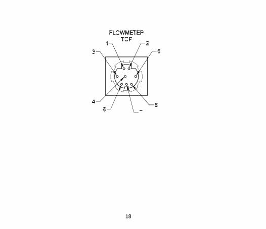
Pin-out for Mini-DIN Connector
Mini-DIN pin-out and cable color code
Mini-DIN Pin No. Function
Color code for TSI cable with tinned wires. PN 1303584
Computer female 9 pin
D-Sub
1 Power Input (+5V) Black
2 Power Ground Green
3 Analog Output (+) Red
4 Analog Ground (-) Brown
5 Analog Pressure Input (+)
Blue
6 RS-232 Receive (in) White 3
7 RS-232 Transmit (out) Yellow 2
8 Logic Ground Gray 5
18

19
Chapter 6 - I/O Signal Description
RS-232 Bi-Directional Interface
Type: 38,400 baud, 8 bit, no parity, 1 stop bit, no flow control. Used to output the flow rate, volume, and temperature signals as well as to select options and modify operating parameters. See Appendix C.
Analog Output of Mass Flow Rate
Factory default: 0 to 4.0 VDC corresponding to 0 to the full scale flow capabilities of the meter. Zero flow and Full Scale flow rate can be re-scaled via the digital serial interface. See Command Set section. You can change the response of the analog output by altering the sample rate (see Command Set section). Note that changing the sampling rate affects both the analog output and the digital outputs.

20
Optional User-Supplied Pressure Signal
You can enhance the accuracy of the mass flow reading in some applications by supplying a signal corresponding to the actual, absolute pressure in the flow tube. The flowmeter uses this information to slightly improve the accuracy of the air density calculation for SLPM. See Appendix B.
Analog Input: 0.0 to 2.0 VDC corresponds to 0 to 101.30 kPa (absolute). Max input = 4.0 V Digital Input of Pressure Data: Pressure data can be sent to the instrument via the digital interface. See Appendix C.

21
Chapter 7 - Specifications
Models 4021 through 4024
Models 4121 through 4122
Flow Measurement Measurement Range Accuracy
0 to 300 Std L/min. Air and O2: 2% of reading or 0.05 Std L/min, whichever is greater, at 21.1°C and 101.3 kPa. See notes 1 through 7 below.
0.01 to 20 Std L/min. Air and O2: 2% of reading or 0.005 Std L/min, whichever is greater, at 21.1°C and 101.3 kPa. See notes 1 through 7 below.

22
Models 4021 through 4024
Models 4121 through 4122
Accuracy (continued) N2: 3% of reading or 0.10 Std L/min, whichever is greater, at 21.1°C and 101.3 kPa. See notes 1 through 7 below.
N2: 3% of reading or 0.010 Std L/min, whichever is greater, at 21.1°C and 101.3 kPa. See notes 1 through 7 below. N2O: 5% of reading or 0.010 Std L/min, whichever is greater, at 21.1°C and 101.3 kPa. See notes 1 through 7 below.
Response Flow Units Digital Output Resolution
Less than 4 msec, 63% of final value at full scale flow. Std L/min or volumetric L/min. Selectable via serial port. 0.01 L/min
Less than 4 msec, 63% of final value at full scale flow. Std L/min or volumetric L/min. Selectable via serial port. 0.001 L/min

23
Models 4021 through 4024
Models 4121 through 4122
Analog Flow Output Range Resolution Maximum Current
0 to 4.0 V = 0 to 300 Std L/min (can be re-scaled via serial interface command) 13 bit 10 mA
0 to 4.0 V = 0 to 20 Std L/min (can be re-scaled via serial interface command) 13 bit 10 mA
Volume Measurement Range
Accuracy
0.01 to 99.9 Liters 2% of Reading at flows greater than 2.5 Std L/min. See notes 1 through 5 and 7 below.
0.01 to 99.9 Liters 2% of Reading at flows greater than 2.5 Std L/min. See notes 1 through 5 and 7 below.

24
Models 4021 through 4024
Models 4121 through 4122
Temperature Measurement Range Accuracy Response
0 to 50°C ±1°C, at flows greater than 1 L/min. See note 2 below.
Less than 75 msec, 63% of final value for 20°C step change in temperature at full scale flow.
0 to 50°C ±1°C, at flows greater than 1 L/min. See note 2 below.
Less than 75 msec, 63% of final value for 20°C step change in temperature at full scale flow.
Digital Interface
RS232: bi-directional, 38.4 k baud, 8 bit, no parity, 1 stop bit, no flow control. See Appendix C for command set.
RS232: bi-directional, 38.4 k baud, 8 bit, no parity, 1 stop bit, no flow control. See Appendix C for command set.
Optional Pressure Input
Via digital or analog input.
Via digital or analog input.
Burst Pressure
Tested to 690 kPa (100 psig) without rupture. Do not exceed 690 kPa (100 psig).
Tested to 690 kPa (100 psig) without rupture.
Do not exceed 690 kPa (100 psig).

25
Models 4021 through 4024
Models 4121 through 4122
Pressure Drop See figure below See figure below
Instrument Temp. Range Operation, Ambient Storage, Ambient
0 to 50°C -20 to 60°C
0 to 50°C -20 to 60°C
Gas Calibrations
Flowmeter must be calibrated to the specified gas. Consult factory.
Flowmeter must be calibrated to the specified gas. Consult factory.
Physical Dimensions External Dimensions Inlet/Outlet Options Weight Flow Body Material Wetted materials
See Chapter 3. See Chapter 3. 170 grams Polycarbonate Polycarbonate, gold, platinum, alumina, Sn/Pb solder
See Chapter 3. See Chapter 3. 63 grams Polycarbonate Polycarbonate, gold, platinum, alumina, Sn/Pb solder
Power Requirements
Power supplied through interface connector. 5.0 VDC ±0.25 V, 300 mA maximum
Power supplied through interface connector. 5.0 VDC ±0.25 V, 300 mA maximum.

26
1 Accuracy stated at standard conditions of 21.1°C and 101.3 kPa.
Add an additional 0.075% of reading per 1°C away from standard conditions when operating within the range of 0°C to 50°C.
Add an additional 0.015% of reading per 1 kPa above 101.3 kPa when pressure compensated and operating within the pressure range of 70 kPa to 170 kPa.
Add an additional 0.022% of reading per 1 kPa below 101.3 kPa when pressure compensated and operating within the pressure range of 70 kPa to 170 kPa.
2 Accuracy stated with gas temperature and flow body temperature within ±10°C of one another.
3 Accuracy stated measuring dry gas (less than 10% R.H.). Consult factory if % RH > 10%
4 Includes ±0.5% of reading repeatability.
5 Volumetric flow rate (L/min) is calculated from the mass flow measurement (Std L/min). The accuracy of the volumetric flow rate depends in part on the flow tube pressure reading that is supplied to the device or assumed by the device. Consult factory for more information.
6 Add 1mV additional uncertainty for analog output. Note that the analog output can be rescaled to reduce the effect of this error
7 Add an additional 1% of reading accuracy allowance when operating within the first five minutes of powering the flowmeter
______________ Specifications are subject to change without notice.

27
Pressure Drop Model 4021–4024
Flow (SLPM)

28
Pressure Drop Model 4121–4122
Flow (SLPM)

29
Appendix A - Back-Pressure and Barometric Pressure - Effect on Accuracy
Even though thermal flowmeters are inherently mass flowmeters (flow is independent of gas density), there is a pressure component related to Mach number which cannot be accounted for without knowing the gas pressure. The 4000/4100 High Performance Linear OEM Mass Flowmeters accept an external pressure signal that the flowmeter can use to perform pressure compensation. The flow rates measured by these devices assume a flow tube pressure of 101.3 kPa (14.69 psia). Deviation from this pressure may require a correction for optimum accuracy. Common causes of pressure deviation include normal system backpressure and changes in barometric pressure due to weather and altitude. If the typical deviation from this “standard pressure” is minor, you may not need to make any correction. See the following chart to determine the additional uncertainty due to changing pressure. If your application requires improved accuracy, the correction for pressure can be done in two ways:

30
1. Store a fixed pressure value in the instrument. If the typical actual pressure is known and relatively constant, you can store the estimated pressure in the instrument’s memory. You can enter this fixed pressure via any of the serial protocols. Examples of this method include a relatively constant backpressure caused by downstream hardware or a correction for high altitude operation. The default pressure is 101.3 kPa. This pressure cannot be saved in the nonvolatile memory—your system must refresh this data each time the flowmeter is powered up or reset. See command SPnnn.nn in Appendix C for more information. See the Command Set sections.
2. Supply a real-time pressure signal to the flowmeter. If you need the
best possible accuracy or if the pressure fluctuates greatly during normal operation, you should supply the flowmeter with a signal from a calibrated, user-supplied pressure sensor. This pressure information can be supplied to the instrument via any of the serial interfaces. The meter also accepts an analog pressure input signal. See the Command Set section.
See the graphs on the following page for the effects of pressure at various flow rates.

31
Pressure Effect vs. Flow Rate Model 4021–4024
Approximate error due to uncompensated
pressure variation
-5%
-4%
-3%
-2%
-1%
0%
1%
2%
3%
4%
5%
0.01 0.1 1 10 100 1000
Flow (slpm)
Err
or
du
e t
o p
ressu
re
(% o
f rd
g)
20 PSIA
18 PSIA
16 PSIA
13 PSIA
11 PSIA
9 PSIA
Flow (SLPM)

32
Pressure Effect vs. Flow Rate Model 4121 - 4122
Pressure Effect vs. Flowrate
Model 4120 - 4122
-10%
-8%
-6%
-4%
-2%
0%
2%
4%
6%
0.0 0.1 1.0 10.0 100.0
Flow (SLPM)
Err
or
du
e t
o p
ressu
re(%
of
rdg
)
8 P S IA
10 P S IA
12 P S IA
18 P S IA
2 0 P S IA
16 P S IA
Flow (SLPM)

33
Appendix B - Standard Flow Rate vs. Volumetric Flow rate
Since thermal flow sensors are sensitive to changes in air density and air velocity, all thermal flowmeters indicate flow rates with reference to a set of standard conditions. For TSI instruments, standard conditions are defined as 21.1°C (70°F) and 101.3 kPa (14.7 psia). Other manufacturers may use different values. Standard flow rate is the flow rate the air would be moving if the temperature and pressure were at standard conditions. It is usually the most useful measure of airflow because it defines the heat-carrying capacity of the air. Volumetric flow rate is the true volume flow of the gas exiting the flowmeter. In some instances, volumetric flow rate rather than standard flow rate may be of interest. To output the volumetric flow rate, the instrument will multiply the standard flow measurement by the following density correction factor:

34
Where Q = Standard flow rate T = Absolute temperature of gas in flow tube P = Absolute pressure in flow tube
TSI flowmeters use Tstd = 21.11ºC and Pstd = 101.3 kPa absolute
Example: The mass flow rate measured by the flowmeter is 100 Std L/min at
15ºC and 117.0 kPa. The flowmeter calculates and outputs the volumetric flow as follows.
min/L78.8411.2115.273
1515.273)100(FlowVolumetric
kPa 117.0
kPa 101.3
Cº
Cº L/min std

35
Appendix C - Digital Serial Interface
Command Set Summary
Data Format
The serial interface settings are fixed as follows:
Baud Rate ............... 38,400 Data Bits ................. 8 Parity ...................... None Stop Bits ................. 1 Flow Control ........... None
Buffering
The flowmeter has an internal software buffer for both transmit and receive operations. Both buffers are 50 bytes long. Command Format
The serial interface commands in this appendix are designated by the larger bold font (ex. DmFTPnnnn). The commands are case sensitive. Upper case letters are used throughout the command set except as designated.

36
These flowmeters use ASCII characters as the input command set. Each command sent to the flowmeter must be terminated by a carriage return (CR = 0x0d). Line feeds (LF = 0x0a ) are ignored.
Some commands allow you to choose either ASCII or binary format for the returned data. Binary data transfers allow for faster operation.
Some operating parameters can be stored in nonvolatile memory to serve as the new power-on defaults (example: sample rate, gas calibration, etc). After selecting the new operating parameter value, initiate the SAVE command to permanently store this new value. If the SAVE command is not initiated, the change to the operating parameter will be lost when the flowmeter is turned off. The factory default operating parameters can always be reset by initiating the DEFAULT command.
The meter send an acknowledge sequence to confirm that the command was received. For ASCII commands, the acknowledge sequence is “OK” <CR> <LF>. For binary commands, a single byte, 0x00 is returned.

37
Commands for Flow Rate, Volume, and Temperature Measurement
DmFTPnnnn Returns Flow rate and Temperature data at an interval equal to the sample rate.
Vmnnnn Returns a volume measurement by integrating flow rate over time.
Measurement Setup Commands
SBTxnnn.nn Sets the begin-trigger level for starting data acquisition.
SETxnnn.nn Sets the end-trigger level for stopping data acquisition.
CBT Clears the begin-trigger level. CET Clears the end-trigger level.
SSRnnnn Sets the sample rate at which the data is returned.
SGn Sets the gas output to be used. SUn Select either Standard or Volumetric units of flow.
SPnnn.nn Sets the pressure to be used for internal pressure compensation.

38
Setup Commands for Analog Output
SASnnn Sets the full-scale flow rate of the analog output.
SAZnnn Sets the zero intercept for the analog output.
SSRnnnn Sets the sample rate at which the data is returned.
Miscellaneous Commands
Rxx Reads the current values of the changeable operating parameters.
SAVE Saves the current values of changeable operating parameters to nonvolatile memory.
DEFAULT Restores the values of changeable operating parameters to factory default settings.
SN Returns the serial number of the flowmeter.
MN Returns the model number of the flowmeter.
REV Returns the internal firmware revision of the flowmeter.
DATE Returns the date of the last calibration.
? Ping command used to tell if the flowmeter is communicating. Returns “OK”.

39
Command Set
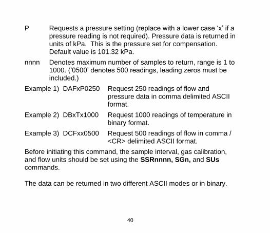
DmFTPnnnn
Returns Flow, Temperature, and Pressure data at an interval equal to the sample rate. The data is returned in the order of Flow, Temperature, and Pressure. All three measurements may be requested or a combination of the three as indicated below. D Denotes data transfer.
m Denotes data format: A = ASCII (comma delimited), B = binary, C = ASCII (<CR> delimited).
F Requests a flow reading (replace with lower case ‘x’ if a flow reading is not desired).
Flow data is returned in units of Standard L/min or L/min (see SUs command).
T Requests a temperature reading (replace with a lower case ‘x’ if a temperature reading is not desired). Temperature data is returned in units of °C.
40
P Requests a pressure setting (replace with a lower case ‘x’ if a pressure reading is not required). Pressure data is returned in units of kPa. This is the pressure set for compensation. Default value is 101.32 kPa.
nnnn Denotes maximum number of samples to return, range is 1 to 1000. (‘0500’ denotes 500 readings, leading zeros must be included.)
Example 1) DAFxP0250 Request 250 readings of flow and pressure data in comma delimited ASCII format.
Example 2) DBxTx1000 Request 1000 readings of temperature in binary format.
Example 3) DCFxx0500 Request 500 readings of flow in comma / <CR> delimited ASCII format.
Before initiating this command, the sample interval, gas calibration, and flow units should be set using the SSRnnnn, SGn, and SUs commands.
The data can be returned in two different ASCII modes or in binary.

41
ASCII Modes Mode A – ASCII, comma delimited If the comma delimited ASCII mode is chosen, the acknowledge sequence of “OK” <CR> <LF> is sent followed by the data. The readings returned are separated by commas and the termination sequence is a <CR> <LF>.
If the command generated an error, an error code “ERRn” <CR> <LF> will be returned where n represents an error code 0 through 9. See the end of this section for a list of possible error codes.
Mode C – ASCII, comma/<CR> delimited
This mode is useful if the captured data will be imported into a spreadsheet program. If Mode C is chosen, the acknowledge sequence of “OK” <CR> <LF> is sent followed by the data. If you requested only one parameter, the returned data will be separated by <CR> <LF>. If you requested more than one parameter, these parameters will be separated by a comma. Each group of readings will then be separated by <CR> <LF>. The termination sequence is <CR> <LF>.
If the command generated an error, an error code “ERRn” <CR> <LF> will be returned where n represents an error code 0 through 9. See the end of this section for a list of possible error codes.

42
Binary Mode If binary mode is chosen, a single byte, 0x00, will be returned, as a command acknowledgment. If a command generated an error, then a single byte will be returned in place of the acknowledgment byte. See the end of this section for a list of error codes. Each reading returns two bytes. The most significant byte is returned first. Flow rate and pressure data are returned as an unsigned integer (0 to 65535) that has been multiplied by 100. Temperature data is returned as a signed integer (-32768 to 32767) that has been multiplied by 100. To convert the returned data, back to its original form, divide the data by 100. Binary transfers terminate, by returning two bytes, in the form 0xFF 0xFF. Check the first reading in each block of data returned (flow, temperature, and pressure), from the unit, for the terminating sequence. No termination sequence will be sent if an error condition
occurred. Special note: a temperature reading of–0.01C would be transmitted as 0xFF 0xFF and could signal an early termination if flow readings were disabled. Data Acquisition for flow, temperature, and pressure If no begin-trigger is set, the data acquisition begins immediately upon processing of the command. If a begin-trigger is set (set with
SBTxnnn.nn), the data acquisition begins as soon as the begin-trigger condition is detected. If no end-trigger is set, nnnn samples will

43
be used in the integral. If an end-trigger is set (set with
SETxnnn.nn), the acquisition will stop either when the end-trigger condition is detected or when nnnn samples has been acquired, whichever comes first. After the command is finished, a termination sequence is sent to signal the end of the transfer.
Example 4) DAFxx0005 Request 5 samples of flow in comma delimited ASCII format (assume begin-trigger is not set).
Flowmeter returns the acknowledgement “OK” <CR> <LF> followed by the flow data and termination sequence 1.10,1.20,1.25,1.23,1.20,1.10 <CR> <LF>
Example 5) DCFTxx0003 Request 3 samples of flow and temperature in comma / <CR> delimited ASCII format (assume begin trigger is not set).
Flowmeter returns the acknowledgement “OK” <CR> <LF> followed by (flow) comma (temperature) <CR> <LF> (flow) comma (temperature) <CR> <LF> (flow) comma (temperature) <CR> <LF>

44
After importation into a spreadsheet it might look like this:
(flow) (temperature)
61.22 19.02
60.01 19.00
59.10 19.00
59.24 18.96
59.38 18.95
Example 6) DBFxx0005 Request 5 samples of flow in binary
format (assume begin-trigger is not set).
Flowmeter returns the single byte acknowledgement 0x00 followed by the flow data and termination sequence: 0x33 0x09 0x33 0x1f 0x33 0x25 0x33 0x2d 0x33 0x2e 0xFF 0xFF
After conversion, the data would look like this: 130.65 130.87 130.93 131.01 131.02

45
Vmnnnn
Returns a volume measurement by integrating flow rate over time.
V Denotes volume measurement. m Denotes data format: A = ASCII, B = binary. nnnn Denotes maximum number of flow samples to integrate,
range is 1 to 9999. (‘0500’ denotes 500 readings, leading zeros must be included.)
Example 1) VA2000 Request a single volume reading by integrating a maximum of 2000 flow samples and return data in ASCII format.
Volume data is returned in units of standard liters or volumetric liters. The units of standard or volumetric is set using the SUs command. The most common units are volumetric liters.
Before initiating this command, the sample interval, gas calibration, and volume units should be set.
The sample interval between data points is set using the SSRnnnn command.
The gas calibration is set using the SGn command.

46
The data can be returned in either ASCII or binary.
If the ASCII mode is chosen, the acknowledge sequence is “OK” <CR>< LF>. Data acquisition begins as soon as the begin-trigger condition is detected. The termination sequence is a <CR> <LF>. If the command generated an error, instead of “OK” <CR> <LF> being returned, an error code “ERRn” <CR> <LF> will be returned where n represents an error code 0 through 9. See the end of this section for a list of possible error codes.
If the binary mode is chosen, the acknowledge sequence is a single byte 0x00. Data acquisition begins as soon as the begin-trigger condition is detected. The reading is represented by 2 bytes. The most significant byte is returned first. The data is represented as an unsigned integer (0 to 65535) that has been multiplied by 100. Therefore, you must divide the integer that is returned by 100 to get the correct result. The termination sequence for binary is 0xFF 0xFF. If the command generated an error, instead of 0x00 being returned a single byte error code will be returned. See the end of this section for a list of possible error codes.

47
Data Acquisition for Volume If a begin-trigger has not been set, the data acquisition begins immediately upon processing of the command. If a begin-trigger has
been set (set with SBTxnnn.nn), the data acquisition begins as soon as the begin-trigger condition is detected. If no end-trigger is set, then nnnn samples will be used in the integral. If an end-trigger is
set (set with SETxnnn.nn), the acquisition will stop either when the end-trigger condition is detected or when nnnn samples has been acquired whichever comes first. After the command is finished, a termination sequence is sent to signal the end of the transfer.
Example 2) VA1000 Request volume measurement with at most 1000 samples, data returned in ASCII.
Flowmeter immediately returns the acknowledgement OK <CR> <LF>. After the end of the data acquisition period when the end-trigger condition is detected or when the specified number of samples have been collected, volume data is transmitted followed by the termination sequence: 130.651 <CR> <LF>

48
Example 3) VB1000 Request volume measurement with at most 1000 samples with the data returned in binary.
Flowmeter returns the single byte acknowledgement 0x00. At the end of the data acquisition period when the end-trigger condition is detected or when the specified number of samples have been collected, volume data is transmitted followed by the termination sequence: 0x33 0x09 0xFF 0xFF. After conversion, the data would look like: 130.65
49
SBTxnnn.nn
Sets the begin-trigger level for starting the data acquisition.
SBT Denotes set begin-trigger. x Denotes trigger source: F = flow, P = pressure.
Denotes positive or negative trigger: + = positive, - = negative.
nnn.nn Set trigger level (‘001.00’ could denote 1.00 Std L/min, leading and trailing zeros must be included).
The set trigger level stays in effect until cleared using the CBT command. The trigger level is also cleared when the flowmeter is turned off or the DEFAULT command is initiated. The SAVE command does not save this parameter
After the command is processed, an acknowledge sequence of “OK” <CR> <LF> is sent. If the command generated an error instead of “OK” <CR> <LF> being sent, an error code of “ERRn” <CR> <LF> will be sent. See the end of this section for a list of possible error codes.
Example 1) SBTF+002.00 Sets a begin-trigger level at a flow of 2.00 Std L/min with positive slope.

50
SETxnnn.nn
Sets the end-trigger level for stopping data acquisition. SET Denotes set end-trigger. x Denotes trigger source: F = flow.
Denotes positive or negative trigger: + = positive, - = negative.
nnn.nn Sets trigger level (‘001.00’ could denote 1.00 Std L/min, leading zeros must be included).
The set trigger level stays in effect until cleared using the CET command. The trigger level is also cleared when the flowmeter is turned off or the DEFAULT command is initiated. The SAVE command does not save this parameter.
After the command is processed, an acknowledge sequence of “OK” <CR> <LF> is sent. If the command generated an error instead of “OK” <CR> <LF> being sent, an error code of “ERRn” <CR> <LF> will be sent. See Appendix A for a list of possible error codes.
Example 1) SETF-002.00 Sets an end-trigger level of a flow of 2.00 Std L/min with negative slope.

51
CBT
Clears the begin-trigger level that was set with SBTx±nnn.nn. Begin-trigger function is disabled. The flowmeter will return an acknowledge sequence of “OK” <CR> <LF> as a response.
Example 1) CBT
CET
Clears the end-trigger level that was set with SETx±nnn.nn. End-trigger function is disabled. The flowmeter will return an acknowledge sequence of “OK” <CR> <LF> as a response.
Example 1) CET

52
SSRnnnn
Sets the sample rate at which the data is returned.
SSR Denotes set sample rate. nnnn Denotes number of milliseconds per sample, range 1 to 1000.
(‘0005’ denotes 5 milliseconds per sample, leading zeros must be included).
In addition to setting the sample rate at which data is accessed through the serial port, this command also controls the update rate of the D/A for the linearized analog flow output signal.
After the command is processed, an acknowledge sequence of “OK” <CR> <LF> is sent. If the command generated an error, an error code of “ERRn” <CR> <LF> will be sent. See the end of this section for a list of possible error codes.
Use the SAVE command to permanently store the selected sample rate as the new power-on default.
Example 1) SSR0010 Sets the sample rate to 10 ms per sample

53
SGn
Sets the gas calibration to be used. Air meters can output signals for more than one gas (see Chapter 1). This command is used to select the desired gas signal output. The default value is specified by the model number. e.g., 4024-6, the default value is nitrogen. Note: oxygen meters will only output oxygen and other meter cannot output oxygen. Also, nitrous oxide is only available on 20 L/min maximum flow rate versions.
SG Denotes set gas. n Denotes the gas calibration desired. 0=Air, 1=100% O2,
2=100% N2O, 6=100% N2.
300 L/min meter air and nitrogen meter can output either air or nitrogen signals.
20 L/min air, nitrous oxide and nitrogen meters output air, nitrous oxide and nitrogen signals.
Both 300 L/min and 20 L/min oxygen meter can only output oxygen signal.
After the command is processed, an acknowledge sequence of “OK” <CR> <LF> is sent. If the command generated an error instead of

54
“OK” <CR> <LF> being sent, an error code of “ERRn” <CR> <LF> will be sent. See the end of this section for a list of possible error codes. Use the SAVE command to permanently store the selected gas calibration as the new power-on default.
Example 1) SG0 Sets the gas calibration to air.
SUn
Select either Standard or Volumetric units of flow for data received through the serial port.
SU Denotes whether flow is measured in Standard units or Volumetric units.
n Denotes which units. S = Std L/min, V = Volumetric L/min.
The 4000 and 4100 series flowmeters are designed to measure flow in units of standard L/min. When selecting volumetric L/min, they perform a flow correction as shown below by measuring gas temperature and pressure. Flow output in volumetric L/min is less accurate due to additional uncertainties encountered when measuring gas temperature and pressure.

55
Pm
Pstd
Tstd
TmQFlowVolumetric *
After the command is processed, an acknowledge sequence of “OK” <CR> <LF> is sent. If the command generated an error instead of “OK” <CR> <LF> being sent, an error code of “ERRn” <CR> <LF> will be sent. See the end of this section for a list of possible error codes.
Use the SAVE command to permanently store the selected flow units as the new power-on default.
Example 1) SUS Selects units of Std L/min for flow rate

56
SPnnn.nn
Sets the pressure to be used for internal pressure compensation and for conversion from standard L/min to volumetric L/min. The unit will default to 101.3 kPa on power up.
SP Denotes Set Pressure. nnn.nn Denotes pressure in kPa.
For units with an analog pressure input, setting this SP parameter to 0 kPa will enable the analog pressure input.
The SAVE command will only save whether the analog pressure input is enabled or disabled. The unit will always power up either with analog pressure input enabled or to the default value of 101.3 kPa.
Example 1) SP108.00 Sets pressure value for calculation to 108.00 kPa
Example 2) SP000.00 Enables analog pressure input

57
SASnnn
Sets the full-scale flow rate of the analog output.
SAS Denotes set scaling factor. nnn Sets full-scale flow rate output (range: 1 to 300 Std L/min) =
4.0 Volts output. (‘010’ denotes 10 Std L/min, leading zeroes must be included.)
The linearized analog output can be configured for various full-scale flow rate values. The factory default is the full scale for of the meter. This value can be changed to improve the resolution of the analog signal by narrowing the range of flow.
After the command is processed, an acknowledge sequence of “OK” <CR> <LF> is sent. If the command generated an error instead of “OK” <CR> <LF> being sent, an error code of “ERRn” <CR> <LF> will be sent. See the end of this section for a list of possible error codes.
Use the SAVE command to permanently store the new full-scale flow value as the new power-on default.
Example 1) SAS100 Sets scaling of analog output to 100 Std L/min = 4.0 Volts

58
SAZnnn
Sets the zero intercept for the analog output. The zero intercept nnn is in units of mV. If nnn = 010, at zero flow the analog output will be 10 mV. This command will accept a negative offset formatted as SZ-nnn. The zero adjustment range is –100 mV to 100 mV. Note that this command sets the zero intercept only and is not a true “zero adjust.” The analog output cannot go negative.
SAZ Denotes Set Analog Zero intercept. nnn Denotes number of mV for the zero flow intercept.
Use the SAVE command to permanently store the new zero intercept value as the new power-on default.
Example 1) SAZ030 Sets zero intercept of zero flow to +30 mV
Example 2) SAZ-050 Sets zero intercept of zero flow to –50 mV. Note that the analog output cannot go negative.

59
SSRnnnn
Sets the sample rate that the data is returned at.
SSR Denotes set sample rate. nnnn Denotes number of milliseconds per sample, range 1 to 1000.
(‘0005’ denotes 5 milliseconds per sample, leading zeros must be included.)
In addition to setting the sample rate at which data is accessed through the serial port, this command also controls the update rate of the D/A for the linearized analog flow output signal.
After the command is processed, an acknowledge sequence of “OK” <CR> <LF> is sent. If the command generated an error, an error code of “ERRn” <CR> <LF> will be sent. See the end of this section for a list of possible error codes.
Use the SAVE command to permanently store the selected sample rate as the new power-on default.
Example 1) SSR0010 Sets the sample rate to 10 ms per sample

60
Rxx
Reads the current values of changeable operating parameters.
R Denotes read current values. xx xx = AS Read analog flow rate scaling factor (returns 1 to
300). xx = AZ Read analog zero intercept (returns –100 to 100) xx = BT Read begin-trigger value (returns xxnnn.nn). xx = ET Read end-trigger value (returns xxnnn.nn). xx = G Read gas calibration (returns 0 to 6). xx = P Read the current pressure setting (returns 0 to 200) xx = SR Read rate (returns 0 to 1000). xx = U Read flow units (returns S or V).
Returns current values in ASCII format. Leading zeroes are not returned.
After the command is processed, an acknowledge sequence of “OK” <CR> <LF> is sent followed by the data and by the termination sequence <CR> <LF>. If the command generated an error instead of “OK” <CR> <LF> being sent, an error code of “ERRn” <CR> <LF> will be sent. See the end of this section for a list of possible error codes.

61
Example 1) RU Read flow units. Returns “OK” <CR> <LF> “S” <CR> <LF>
SAVE
Saves the current values for changeable operating parameters to the internal nonvolatile memory. The flowmeter will be restored to this configuration when powered up. The following parameters are saved:
Analog Pressure Input enable (see SPnnn.nn command) Analog full scale flow rate (SASnnn) Analog zero intercept (SAZnnn) Gas (SGn) Sample Rate (SSRnnn) Flow Units (SUn)
After the command is processed, an acknowledge sequence of “OK” <CR> <LF> is sent. If the command generated an error, an error code of “ERRn” <CR> <LF> will be sent. See the end of this section for a list of possible error codes.

62
DEFAULT
Returns the values for sample rate, calibration gas, standard/volumetric flow units, and analog output scaling to the default factory settings. To make these values the new power-on default, the SAVE command must be executed following the DEFAULT command. This command also clears both the begin- and end-trigger values.
Example: The normal factory default parameter settings are: Analog Pressure Setting: 101.3 kPa Sample Rate: 10 ms Gas Calibration: 0 = Air Flow Units: Standard Analog Output Scaling: The full scale flow rate of the
meter. Analog Zero Intercept: 0 mV Beginning Trigger Disabled End Trigger Disabled
Depending on the configuration of your flowmeter, these default settings may be different.

63
After the command is processed, an acknowledge sequence of “OK” <CR> <LF> is sent. If the command generated an error, an error code of “ERRn” <CR> <LF> will be sent. See the end of this section for a list of possible error codes.
SN
Returns the serial number of the flowmeter in ASCII. The serial number is an alpha-numeric string terminated by a <CR> <LF>. The string can be a maximum of 16 characters in length plus the terminating <CR> <LF>. If the command generated an error, an error code of “ERRn” <CR> <LF> will be sent. See the end of this section for a list of possible error codes.
Example 1) SN Returns “40249806004” <CR> <LF>

64
MN
Returns the model number of the flowmeter in ASCII. The model number is an alpha-numeric string terminated by a <CR> <LF>. The string can be a maximum of 12 characters in length plus the terminating <CR> <LF>. If the command generated an error, an error code of “ERRn” <CR> <LF> will be sent. See the end of this section for a list of possible error codes.
Example 1) MN Returns “4024” <CR> <LF>
REV
Returns the internal firmware revision of the flowmeter in ASCII. The revision is an alpha-numeric string terminated by a <CR> <LF>. The string can be a maximum of 3 characters in length plus the terminating <CR> <LF>. If the command generated an error, an error code of “ERRn” <CR> <LF> will be sent. See the end of this section for a list of possible error codes.
Example 1) REV Returns “1.0” <CR> <LF>

65
DATE
Returns the date of the last calibration in ASCII. The format of the string is “month/day/year.” The date is an alpha-numeric string terminated by a <CR> <LF>. The string can be a maximum of 8 characters in length plus the terminating <CR> <LF>. If the command generated an error, an error code of “ERRn” <CR> <LF> will be sent. See the end of this section for a list of possible error codes.
Example 1) DATE Returns “12/24/03” <CR> <LF>
?
This is a ping command used to tell if the flowmeter is communicating. The flowmeter will return an acknowledge sequence of “OK” <CR> <LF> as a response.
Example 1) ? Returns “OK” <CR> <LF>

66
Error Codes
1 Unrecognizable command – The flowmeter uses the length of the command and the first few letters (how many letters depends on the command) to recognize a valid command.
2 Number out of range – The number entered as the operand to a command was out of the specified range or unrecognizable.
3 Invalid mode – One or more requested options to a command were invalid.
4 Command not possible – The supplied operands describe a command that is beyond the functional capability of the flowmeter.
8 Internal error – An internal failure was detected.

TSI Incorporated – Visit our website www.tsi.com for more information. USA Tel: +1 800 874 2811 UK Tel: +44 149 4 459200 France Tel: +33 1 41 19 21 99 Germany Tel: +49 241 523030
India Tel: +91 80 67877200 China Tel: +86 10 8219 7688 Singapore Tel: +65 6595 6388
P/N 1980430 Rev K ©2016 TSI Incorporated Printed in U.S.A.
*1980430*