Embed Size (px)
Citation preview
© 2004 - 2007 © 2004 - 2010 9000 Virginia Manor Rd Ste 290, Beltsville MD 20705 | 301-474-0607 | www.dfrsolutions.com © 2004 – 2010
Design for Reliability
DfR Solutions Webinar
November 14, 2013

© 2004 - 2007 © 2004 - 2010 9000 Virginia Manor Rd Ste 290, Beltsville MD 20705 | 301-474-0607 | www.dfrsolutions.com
o DfR: A process for ensuring the reliability of a product
or system during the design stage before physical
prototype
o Reliability: The measure of a product’s ability to
o …perform the specified function
o …at the customer (with their use environment)
o …over the desired lifetime
What is Design for Reliability (DfR)?

© 2004 - 2007 © 2004 - 2010 9000 Virginia Manor Rd Ste 290, Beltsville MD 20705 | 301-474-0607 | www.dfrsolutions.com
Why DfR? Get it Right the First Time!
P. Smith and D. Reinertsen. Developing Products In Half The Time (New York Van Nostrand Reinhold. 1991). 4.
Faster time to market

© 2004 - 2007 © 2004 - 2010 9000 Virginia Manor Rd Ste 290, Beltsville MD 20705 | 301-474-0607 | www.dfrsolutions.com
Reduce Costs by Improving
Reliability Upfront
Why DfR? Lower Cost of Quality!

© 2004 - 2007 © 2004 - 2010 9000 Virginia Manor Rd Ste 290, Beltsville MD 20705 | 301-474-0607 | www.dfrsolutions.com
Lower Cost of Quality (cont.)
Statement from a Major OEM of Server Architecture
Margins are so tight in this business that
reliability plays a major role in our financial
performance.
If a unit requires more than one service call
during its lifetime, our profit margin has been
effectively eliminated.
© 2004 - 2007 © 2004 - 2010 9000 Virginia Manor Rd Ste 290, Beltsville MD 20705 | 301-474-0607 | www.dfrsolutions.com
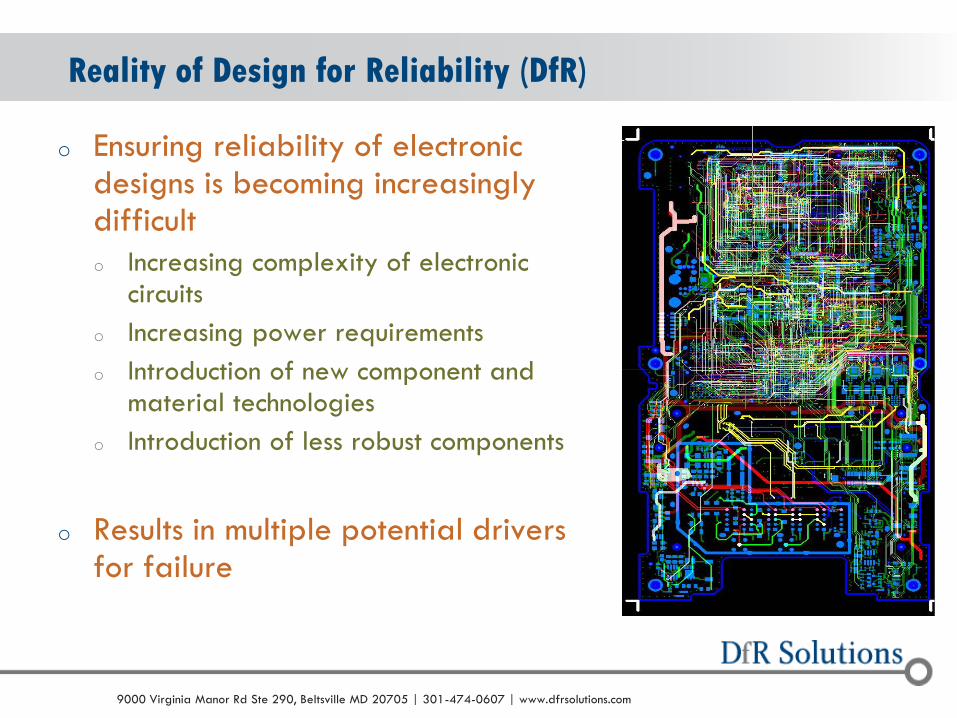
Reality of Design for Reliability (DfR)
o Ensuring reliability of electronic designs is becoming increasingly difficult
o Increasing complexity of electronic circuits
o Increasing power requirements
o Introduction of new component and material technologies
o Introduction of less robust components
o Results in multiple potential drivers for failure
© 2004 - 2007 © 2004 - 2010 9000 Virginia Manor Rd Ste 290, Beltsville MD 20705 | 301-474-0607 | www.dfrsolutions.com
Reality (cont.)
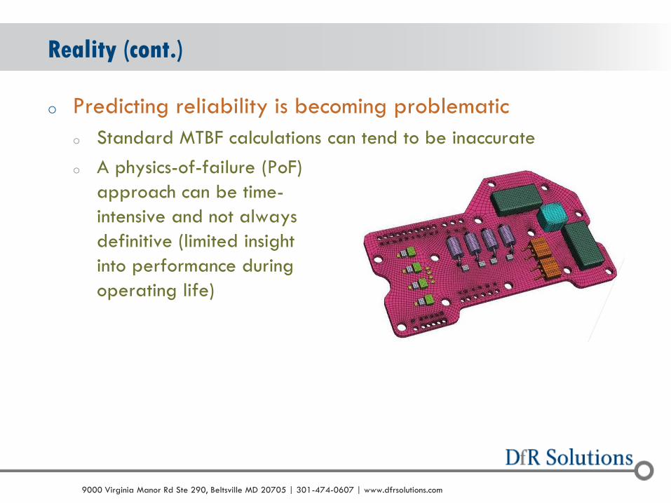
o Predicting reliability is becoming problematic
o Standard MTBF calculations can tend to be inaccurate
o A physics-of-failure (PoF)
approach can be time-
intensive and not always
definitive (limited insight
into performance during
operating life)

© 2004 - 2007 © 2004 - 2010 9000 Virginia Manor Rd Ste 290, Beltsville MD 20705 | 301-474-0607 | www.dfrsolutions.com
Issues with DfR
o The process of Design for Reliability (DfR) is achieving a
high profile in the electronics industry
o DfR is even on Wikipedia!
o Part of an overall Design for Excellence (DfX)
o Numerous organizations
now offer DfR training
tools (courses, books, etc.)
o Response to market demand
© 2004 - 2007 © 2004 - 2010 9000 Virginia Manor Rd Ste 290, Beltsville MD 20705 | 301-474-0607 | www.dfrsolutions.com
Issues with Standard DfR Tools
o Too broad in focus (not electronics focused)
o Too much emphasis on techniques (e.g., FMEA and FTA)
and not answers
o FMEA/FTA rarely identify DfR issues because of limited focus on
the failure mechanism
o Incorporation of HALT and failure analysis (HALT is test,
not DfR; failure analysis is too late)
o Frustration with ‘test-in reliability’, even HALT, has been part of
the recent focus on DfR

© 2004 - 2007 © 2004 - 2010 9000 Virginia Manor Rd Ste 290, Beltsville MD 20705 | 301-474-0607 | www.dfrsolutions.com
Issues with DfR Tools (e.g., HALT)
o Highly Accelerated Life Testing (HALT)
o Based on sound fundamental engineering
o 1. Know your margins!
o 2. Not everything can be predicted (how to predict the time
required for a screw to come loose?)
o However…
o There are no failure modes in HALT that can not be addressed
through strong DfR activities
o Best in Class organizations will actually predict HALT failure
modes before HALT

© 2004 - 2007 © 2004 - 2010 9000 Virginia Manor Rd Ste 290, Beltsville MD 20705 | 301-474-0607 | www.dfrsolutions.com
o Start at Concept / Block-Diagram Stage
o Specifications are key
o Focus on electrical and software reliability
o Part selection
o Derating and uprating
o DfM cannot be separated from DfR
o Wearout mechanisms and physics of failure
o Predicting degradation in today’s electronics
How Does DfR (Solutions) do DfR?

© 2004 - 2007 © 2004 - 2010 9000 Virginia Manor Rd Ste 290, Beltsville MD 20705 | 301-474-0607 | www.dfrsolutions.com
o Failure to capture and understand product specifications
at this stage lays the groundwork for mistakes at
schematic and layout
o Reliability expectations
o Use environment
o Dimensional constraints
Concept / Block Diagram
© 2004 - 2007 © 2004 - 2010 9000 Virginia Manor Rd Ste 290, Beltsville MD 20705 | 301-474-0607 | www.dfrsolutions.com
o Typical reliability metrics: Desired Lifetime / Product Performance
o Desired lifetime
o Defined as when the customer will be satisfied
o Should be actively used in development of part and product qualification
o Product performance
o Returns during the warranty period
o Survivability over lifetime at a set confidence level
o Try to avoid MTBF or MTTF
Reliability Goals
© 2004 - 2007 © 2004 - 2010 9000 Virginia Manor Rd Ste 290, Beltsville MD 20705 | 301-474-0607 | www.dfrsolutions.com
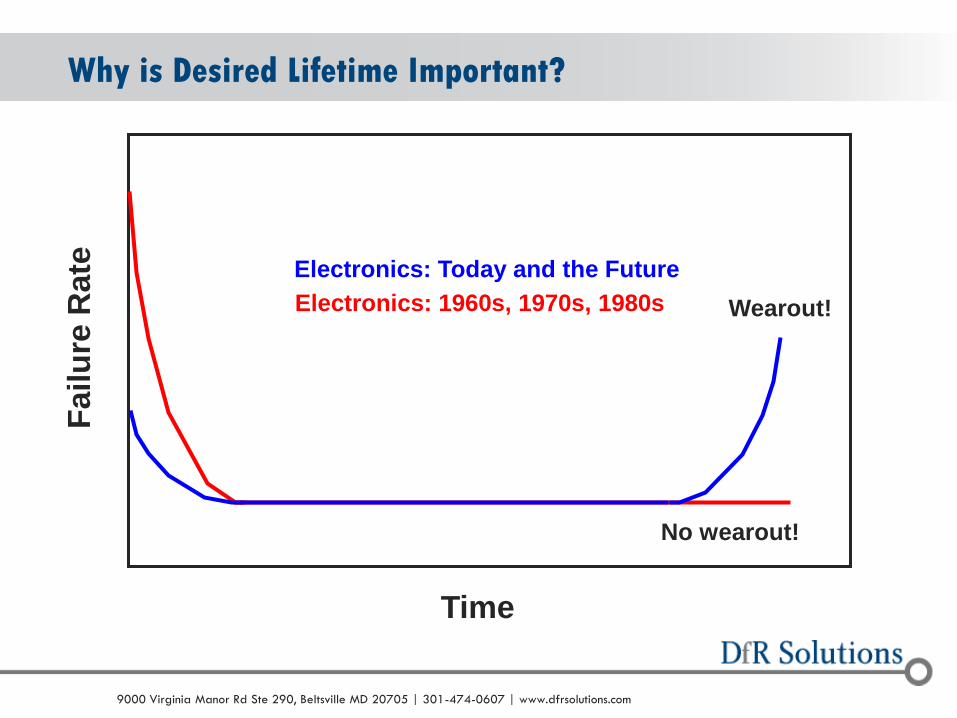
Why is Desired Lifetime Important? F
ail
ure
Rate
Time
Electronics: 1960s, 1970s, 1980s
No wearout!
Electronics: Today and the Future
Wearout!
© 2004 - 2007 © 2004 - 2010 9000 Virginia Manor Rd Ste 290, Beltsville MD 20705 | 301-474-0607 | www.dfrsolutions.com
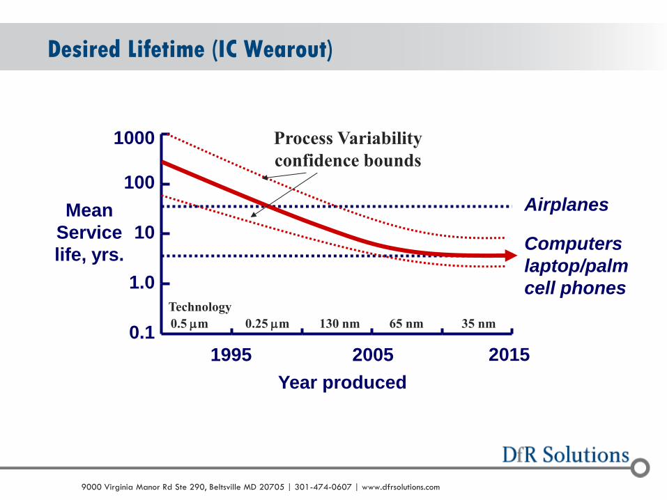
Desired Lifetime (IC Wearout)
1995 2005 2015
0.1
1.0
10
100
1000
Year produced
Mean
Service
life, yrs. Computers
laptop/palm
cell phones
Airplanes
0.5 mm 0.25 mm 130 nm 65 nm 35 nm
Process Variability
confidence bounds
Technology

© 2004 - 2007 © 2004 - 2010 9000 Virginia Manor Rd Ste 290, Beltsville MD 20705 | 301-474-0607 | www.dfrsolutions.com
o More silicon, less plastic (CSP, Stacked Die, etc.)
o Elimination of leads (DFN, QFN, BTC, etc.)
Desired Lifetime (Solder Wearout)
BOARD LEVEL ASSEMBLY AND RELIABILITY
CONSIDERATIONS FOR QFN TYPE PACKAGES,
Ahmer Syed and WonJoon Kang, Amkor Technology.

© 2004 - 2007 © 2004 - 2010 9000 Virginia Manor Rd Ste 290, Beltsville MD 20705 | 301-474-0607 | www.dfrsolutions.com
Product Repair rate (%)
[First 3 Yrs]
Desktop PC 37
Laptop PC 33
Refrigerator: side-by-side (with icemaker and
dispenser) 28
Washing machine 22
Refrigerator: top- and bottom-freezer (with icemaker) 17
Projection TV 16
Vacuum cleaner (excluding belt replacement) 13
Dishwasher 13
Clothes dryer 13
Microwave oven (over-the-range) 12
Electric range 11
Camcorder 8
Digital camera 8
Refrigerator: top- and bottom-freezer (without
icemaker) 8
TV: 30- to 36-inch 7
TV: 25- to 27-inch 5
Product Performance: Warranty Returns
o Consumer Electronics
o Table on right
o Low Volume, Non Hi-Rel
o 1 to 2%
o Industrial Controls
o 500 to 2000 ppm (1st Year)
o Depends on complexity, production volumes, and risk sensitivity
o Automotive
o 1 to 5% (Electrical, 1st Year)
o Can also be reported as problems per 100 vehicles
o Percent of revenue (1.2 to 4.5) Consumer Reports 2006

© 2004 - 2007 © 2004 - 2010 9000 Virginia Manor Rd Ste 290, Beltsville MD 20705 | 301-474-0607 | www.dfrsolutions.com
o Your product can not
have a field
performance better
than its parts!
o Disk drives,
microprocessors, fans,
memory, power supplies
are challenging
Product Performance: Disk Drives
http://blog.backblaze.com/2013
/11/12/how-long-do-disk-drives-
last/

© 2004 - 2007 © 2004 - 2010 9000 Virginia Manor Rd Ste 290, Beltsville MD 20705 | 301-474-0607 | www.dfrsolutions.com
Product Performance: Survivability
o Some companies set reliability goals based on survivability o Often bounded by confidence levels
o Example: 95% reliability with 90% confidence over 15 years
o Advantages o Helps set bounds on test time and sample size
o Does not assume a failure rate behavior (decreasing, increasing, steady-state)
o Disadvantages o Can be re-interpreted through mean time to failure (MTTF) or
mean time between failures (MTBF)
© 2004 - 2007 © 2004 - 2010 9000 Virginia Manor Rd Ste 290, Beltsville MD 20705 | 301-474-0607 | www.dfrsolutions.com
Limitations of MTTF/MTBF
o MTBF/MTTF calculations tend to assume that failures are
random in nature
o Provides no motivation for failure avoidance
o Easy to manipulate numbers
o Tweaks are made to reach desired MTBF
o E.g., quality factors for each component are modified
o Often misinterpreted
o 50K hour MTBF does not mean no failures in 50K hours
o Better fit towards logistics and procurement, not failure
avoidance

© 2004 - 2007 © 2004 - 2010 9000 Virginia Manor Rd Ste 290, Beltsville MD 20705 | 301-474-0607 | www.dfrsolutions.com
o Approach 1: Use of specifications o MIL-STD-810, MIL-HDBK-310, IPC-SM-
785, Telcordia GR3108, IEC 60721-3, etc.
o Low cost and can be very comprehensive
o Agreement throughout the industry
o Major disadvantage is always less or greater than actual (by how much, unknown)
o Approach 2: Based on actual measurements o Determine average and realistic
worst-case
o Identify all failure-inducing loads
o Include all environments
Identify Field Environment
IPC SM785
MIL HDBK310
© 2004 - 2007 © 2004 - 2010 9000 Virginia Manor Rd Ste 290, Beltsville MD 20705 | 301-474-0607 | www.dfrsolutions.com
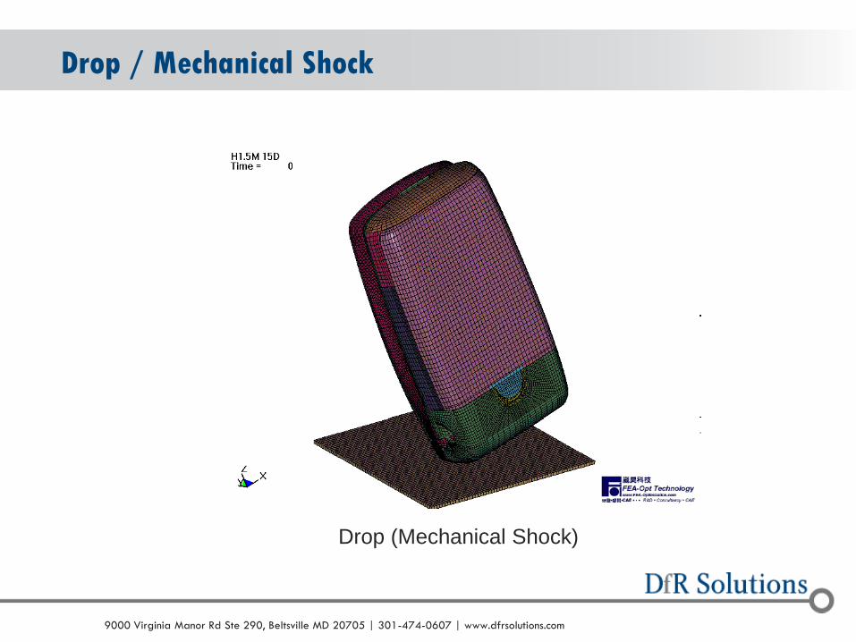
Drop / Mechanical Shock
Drop (Mechanical Shock)
© 2004 - 2007 © 2004 - 2010 9000 Virginia Manor Rd Ste 290, Beltsville MD 20705 | 301-474-0607 | www.dfrsolutions.com
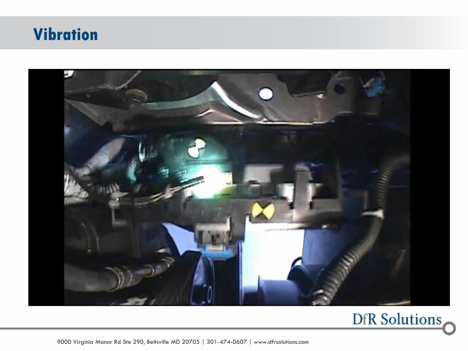
Vibration
© 2004 - 2007 © 2004 - 2010 9000 Virginia Manor Rd Ste 290, Beltsville MD 20705 | 301-474-0607 | www.dfrsolutions.com
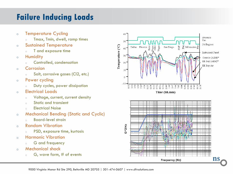
o Temperature Cycling o Tmax, Tmin, dwell, ramp times
o Sustained Temperature o T and exposure time
o Humidity o Controlled, condensation
o Corrosion o Salt, corrosive gases (Cl2, etc.)
o Power cycling o Duty cycles, power dissipation
o Electrical Loads o Voltage, current, current density
o Static and transient
o Electrical Noise
o Mechanical Bending (Static and Cyclic) o Board-level strain
o Random Vibration o PSD, exposure time, kurtosis
o Harmonic Vibration o G and frequency
o Mechanical shock o G, wave form, # of events
Failure Inducing Loads

© 2004 - 2007 © 2004 - 2010 9000 Virginia Manor Rd Ste 290, Beltsville MD 20705 | 301-474-0607 | www.dfrsolutions.com
Field Environment: Temperatures in USA
Month Cycles/Year Ramp Dwell Max. Temp (oC) Min. Temp. (
oC)
Jan.+Feb.+Dec. 90 6 hrs 6 hrs 20 5
March+November 60 6 hrs 6 hrs 25 10
April+October 60 6 hrs 6 hrs 30 15
May+September 60 6 hrs 6 hrs 35 20
June+July+August 90 6 hrs 6 hrs 40 25
Temperature Avg. U.S.
CLIM Data
Avg. U.S.
Weighted by Registration
(Source: Confidential)
Phoenix
(hrs/yr)
U.S.
Worst Case
(hrs/yr)
95F (35C) 0.375% 0.650% 11% (948) 13% (1,140)
105F (40.46C) 0.087% 0.050% 2.3% (198) 3.8% (331)
115F (46.11C) 0.008% 0.001% 0.02% (1.4) 0.1% (9)

© 2004 - 2007 © 2004 - 2010 9000 Virginia Manor Rd Ste 290, Beltsville MD 20705 | 301-474-0607 | www.dfrsolutions.com
Field Environment: Closed Container Temp
Container and Ambient Temperature
15.0
25.0
35.0
45.0
55.0
65.0
75.0
0 50 100 150 200 250 300 350 400 450
Hours
Te
mp
era
ture
(°C
)
Container Temp (°C)
Outdoor Temp (°C)Temp.
Variation
Trucking
Container

© 2004 - 2007 © 2004 - 2010 9000 Virginia Manor Rd Ste 290, Beltsville MD 20705 | 301-474-0607 | www.dfrsolutions.com
o Often very well defined in developed countries, but new
markets can introduce surprises
o China: Can have issues with grounding (connected to
rebar?)
o India: Numerous brownouts (several a day)
o Mexico: Voltage surges
Field Environment: Electrical
© 2004 - 2007 © 2004 - 2010 9000 Virginia Manor Rd Ste 290, Beltsville MD 20705 | 301-474-0607 | www.dfrsolutions.com
o Keep dimensions loose at this stage
o Large number of hardware mistakes driven by arbitrary size constraints
o Examples include poor interconnect strategies and poor choices in component selection
o Case study: Use of 0201 chip components
o Tight dimensional requirements push designer towards wholesale placement of 0201 components
o 0201 is not yet an appropriate technology for systems requiring reliability
o Result: Major issues at customers
o Use the Toyota approach
Dimensions

© 2004 - 2007 © 2004 - 2010 9000 Virginia Manor Rd Ste 290, Beltsville MD 20705 | 301-474-0607 | www.dfrsolutions.com
o Anti-V Model Product Development
What is the Toyota Approach?

© 2004 - 2007 © 2004 - 2010 9000 Virginia Manor Rd Ste 290, Beltsville MD 20705 | 301-474-0607 | www.dfrsolutions.com
o Western engineers o Define several product concepts
o Select the one that has the most promise
o Draw up specifications and divide them into subsystems;
o Subsystems are designed, built and rolled up for system testing.
o Failures? Rework the specs and the designs accordingly (non-optimized and confusing endeavor)
Toyota Approach
o Toyota engineers o Efforts concentrated at lowest
possible design level
o Thorough understanding of the technology of a subsystem so it can be used appropriately in future designs
Toyota's development engineers are 4X as productive as U.S. counterparts.
Why?
Focus on learning as much as possible
Use of that knowledge to develop a stream of excellent products

© 2004 - 2007 © 2004 - 2010 9000 Virginia Manor Rd Ste 290, Beltsville MD 20705 | 301-474-0607 | www.dfrsolutions.com
o Traditional approach: Design radiator for a specific vehicle based on mechanical specifications written for that vehicle
o Toyota considers a range of radiator solutions based on cooling capacities and the cooling demands of various engines that might be used.
o How the radiator actually fits into a vehicle would be kept loose so that Toyota's knowledge of radiator technology could be used to create the optimum design
o Toyota's system is "test & design" rather than the traditional "design & test."
o Toyota engineers test at the fundamental knowledge level so they don't have to test at the later, more expensive stages of design and prototyping
Toyota Example: Radiators

© 2004 - 2007 © 2004 - 2010 9000 Virginia Manor Rd Ste 290, Beltsville MD 20705 | 301-474-0607 | www.dfrsolutions.com
Electrical and Software Reliability
o Electrical reliability is often overlooked by many
reliability engineers because
o They don’t have electrical backgrounds
o Political concerns (don’t step on engineering toes)
o However, electrical design does not always assess
electrical issues from a reliability standpoint
o Classic electrical engineering, especially today, lives in a virtual
world
© 2004 - 2007 © 2004 - 2010 9000 Virginia Manor Rd Ste 290, Beltsville MD 20705 | 301-474-0607 | www.dfrsolutions.com
o Power Stability
o Design for EMI/EMC
o Don’t worry about compliance; worry if it will work!
o Before testing
o Design for EOS/ESD
o Parts are increasingly ESD sensitive
o Portability/mobility increases the potential for exposure to EOS/ESD events
o Buffering
Electrical and Software Reliaiblity (Key Areas)

© 2004 - 2007 © 2004 - 2010 9000 Virginia Manor Rd Ste 290, Beltsville MD 20705 | 301-474-0607 | www.dfrsolutions.com
ESD Sensitivity and Location
o Use ESD Protection on all susceptible parts
o Box or System I/O
o ESD Rating < Class 2 HBM IEC (4000V, 150pf, 330 Ohm) MANDATORY
o Internal Components (not exposed to outside connectors)
o ESD Rating <= Class 1 ANSI (0-999V) MANDATORY
o ESD Rating < Class 2 ANSI (2000V) WHEREVER POSSIBLE
o High Speed, RF and GaAs parts will be sensitive to ESD
[Class 0 (<250V) or Class 1A (<500V)]
o Place ESD sensitive components and traces to avoid locations where the board
may be handled
o Avoid Coupled ESD events – Do not route traces to ESD sensitive parts near lines
connected to the outside world
o Install protective devices before ESD sensitive parts (Class 1 or lower)

© 2004 - 2007 © 2004 - 2010 9000 Virginia Manor Rd Ste 290, Beltsville MD 20705 | 301-474-0607 | www.dfrsolutions.com
Evaluate Potential ESD
o If ESD sensitive parts are used in design, the circuitry connected to
device pins should be evaluated
o Insure that it provides “attenuation” to prevent voltage in excess of the
parts ESD rating from developing in case the pin or connected traces are
contacted during board handling or system assembly.
o Often the recommended circuit components for operation of the part
will provide adequate ESD protection.
o This should be verified by analysis or simulation and extra protection
added as required to limit the voltage seen at the part.
o Assumptions for analysis/simulation
o 2000V,1.5K, 100pf for Internal circuits
o 4000V, 330 Ohms, 150pf for I/Os
© 2004 - 2007 © 2004 - 2010 9000 Virginia Manor Rd Ste 290, Beltsville MD 20705 | 301-474-0607 | www.dfrsolutions.com
o KIS: Keep it Simple o New component technology can be very attractive
o Not always appropriate for high reliability embedded systems
o Be conservative
o BUT, don’t be too conservative (old technology quickly becomes private labeled; i.e., ‘lawful counterfeiting’)
o Reality: Marketing hype FAR exceeds actual implementation o Component manufacturers typically use portable sales to boost
numbers
o Claim: We have built 100’s of millions of these components without a single return!
o Actuality: All sales were to two cell phone customers with lifetimes of 18 months
Component Selection
© 2004 - 2007 © 2004 - 2010 9000 Virginia Manor Rd Ste 290, Beltsville MD 20705 | 301-474-0607 | www.dfrsolutions.com
o Even when used by hi-rel companies, some modifications
may have been made
o Example: State-of-the-art crystal oscillator required specialized
assembly to avoid failures one to three years later in the field
o Prior examples of where care should have been taken
o New technologies: X5R dielectric, SiC diodes, etc.
o New packaging: Quad flat pack no lead (QFN), 0201, etc.
Component Selection (cont.)

© 2004 - 2007 © 2004 - 2010 9000 Virginia Manor Rd Ste 290, Beltsville MD 20705 | 301-474-0607 | www.dfrsolutions.com
o Definition
o A specification provided by
component manufacturers
that guides the user as to the
appropriate range of
stresses over which the
component is guaranteed to
function
o Typical parameters
o Voltage
o Current
o Power
o Temperature
Derating: Component Ratings
© 2004 - 2007 © 2004 - 2010 9000 Virginia Manor Rd Ste 290, Beltsville MD 20705 | 301-474-0607 | www.dfrsolutions.com
o Derating is the practice of limiting stress on electronic parts to levels below the manufacturer’s specified ratings
o Guidelines can vary based upon environment (“severe, protected, normal” or “space, aircraft, ground”)
o One of the most common design for reliability (DfR) methods
o Goals of derating
o Maintain critical parameters during operation (i.e., functionality)
o Provide a margin of safety from deviant lots
o Achieve desired operating life (i.e., reliability)
o Sources of derating guidelines
o Governmental organizations and 3rd parties
o OEM’s
o Component manufacturers
o Derating is assessed through component stress analysis
Derating

© 2004 - 2007 © 2004 - 2010 9000 Virginia Manor Rd Ste 290, Beltsville MD 20705 | 301-474-0607 | www.dfrsolutions.com
Derating Guidelines (Examples)

© 2004 - 2007 © 2004 - 2010 9000 Virginia Manor Rd Ste 290, Beltsville MD 20705 | 301-474-0607 | www.dfrsolutions.com
o Failure to perform component stress analysis can
result in higher warranty costs, potential recalls
o Eventual costs can be in the millions of dollars
o Perspective from Chief Technologist at major
Original Design Manufacturer (ODM)
Criticality of Component Stress Analysis
“…based on our experience, we believe a
significant number of field returns, and the
majority of no-trouble-founds (NTFs), are
related to overstressed components.”

© 2004 - 2007 © 2004 - 2010 9000 Virginia Manor Rd Ste 290, Beltsville MD 20705 | 301-474-0607 | www.dfrsolutions.com
o Where are the derating mistakes?
o Problem #1: Designers do not derate
o Failure to perform component stress analysis
o Problem #2: Derating does not have a practical or
scientific foundation
o Extraordinary measures are taken when inappropriate
o Derating is excessive: ‘The more, the better’ rule
Derating Failures
© 2004 - 2007 © 2004 - 2010 9000 Virginia Manor Rd Ste 290, Beltsville MD 20705 | 301-474-0607 | www.dfrsolutions.com
o Analog / Power Designs
o Derating is typically overlooked during transient events
o Especially turn-on, turn-off
o Digital
o Excessive number of components and connections tends to limit
attempts to perform component stress analysis
Failure to Derate: Common Examples

© 2004 - 2007 © 2004 - 2010 9000 Virginia Manor Rd Ste 290, Beltsville MD 20705 | 301-474-0607 | www.dfrsolutions.com
o To be effective, derating must have a practical and scientific foundation
o Problem: Manufacturer’s ratings are not always based on a practical and scientific foundation
o Manufacturers’ viewpoint
o Ratings are based on specific design rules based on materials, process, and reliability testing
o The reality
o Ratings can be driven by tradition and market forces as much as science
o Best practice
o Based on data from field returns
o Based on test to failure qualification (especially for new suppliers)
The Foundation of Derating

© 2004 - 2007 © 2004 - 2010 9000 Virginia Manor Rd Ste 290, Beltsville MD 20705 | 301-474-0607 | www.dfrsolutions.com
o Tantalum capacitor
o MnO2 cathode
o Derating based on desired
failure rate
o 10 ppm at startup
o Why not 10 ppm failure
rate at rated voltage?
o Was 0.3% failure rate
acceptable?
o 50% derating is a legacy
Manufacturer’s Derating (example)
Courtesy of Kemet
© 2004 - 2007 © 2004 - 2010 9000 Virginia Manor Rd Ste 290, Beltsville MD 20705 | 301-474-0607 | www.dfrsolutions.com
o Step 1: Derating guidelines should be based on
component performance, not ratings
o Test to failure approach (i.e., HALT of components)
o Quantifies life cycle cost tradeoffs
o For smaller OEMs, limit this practice to critical components
Derating Decision Tree

© 2004 - 2007 © 2004 - 2010 9000 Virginia Manor Rd Ste 290, Beltsville MD 20705 | 301-474-0607 | www.dfrsolutions.com
o Step 2: Derating guidelines should be based on
recommendations from the component manufacturer
o They built it; they should know it
o Don’t trust the manufacturer? Use someone else
o Step 3: Derating guidelines should be based on customer
requirements
o Step 4: Derating guidelines should be based industry-
accepted specification/standard
Derating Decision Tree (cont.)
Be flexible, not absolute

© 2004 - 2007 © 2004 - 2010 9000 Virginia Manor Rd Ste 290, Beltsville MD 20705 | 301-474-0607 | www.dfrsolutions.com
o The biggest mistake at this stage of the design?
o Manufacturability
o Problem is getting better, but suppliers will always try to
build what you send them
o If it doesn’t work, rework!
o Even some design for manufacturability (DfM) is limited; major
problems are not always addressed
Layout / Mechanicals
© 2004 - 2007 © 2004 - 2010 9000 Virginia Manor Rd Ste 290, Beltsville MD 20705 | 301-474-0607 | www.dfrsolutions.com
o Definition
o The process of ensuring a design can be consistently manufactured
by the designated supply chain with a minimum number of defects
o Requirements
o An understanding of best practices (what fails during
manufacturing?)
o An understanding of the limitations of the supply chain (you can’t
make a silk purse out of a sow’s ear)
DfM
© 2004 - 2007 © 2004 - 2010 9000 Virginia Manor Rd Ste 290, Beltsville MD 20705 | 301-474-0607 | www.dfrsolutions.com
o DfM is often overlooked in the design process
o Reasons
o Design team often has poor insight into supply chain (reverse
auction, anyone?)
o OEM requests no feedback on DfM from supply chain
o DfM feedback consists of standard rule checks (no insight)
o DfM activities at the OEM are not standardized or distributed
DfM Failures
© 2004 - 2007 © 2004 - 2010 9000 Virginia Manor Rd Ste 290, Beltsville MD 20705 | 301-474-0607 | www.dfrsolutions.com
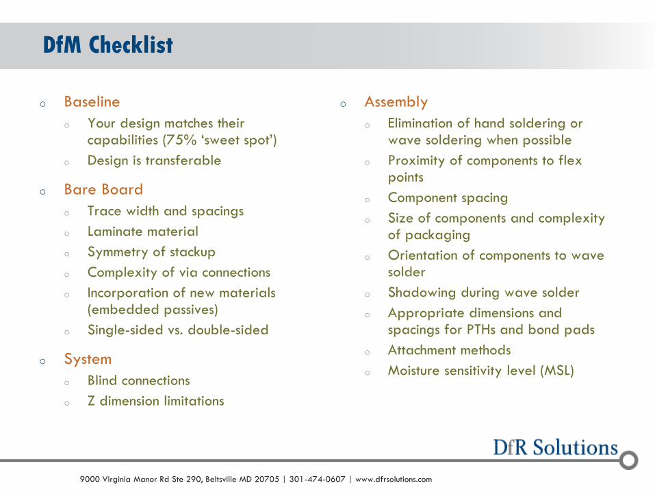
DfM Checklist
o Baseline
o Your design matches their capabilities (75% ‘sweet spot’)
o Design is transferable
o Bare Board
o Trace width and spacings
o Laminate material
o Symmetry of stackup
o Complexity of via connections
o Incorporation of new materials (embedded passives)
o Single-sided vs. double-sided
o System
o Blind connections
o Z dimension limitations
o Assembly
o Elimination of hand soldering or wave soldering when possible
o Proximity of components to flex points
o Component spacing
o Size of components and complexity of packaging
o Orientation of components to wave solder
o Shadowing during wave solder
o Appropriate dimensions and spacings for PTHs and bond pads
o Attachment methods
o Moisture sensitivity level (MSL)

© 2004 - 2007 © 2004 - 2010 9000 Virginia Manor Rd Ste 290, Beltsville MD 20705 | 301-474-0607 | www.dfrsolutions.com
Solder Process
Defects per Million Opportunities
Standard Best in Class
Hand 5000 N/A
Wave 500 20 - 100
Reflow 50 <10
Designing for Defects
o Designs that avoid manual soldering operations
reduce defects

© 2004 - 2007 © 2004 - 2010 9000 Virginia Manor Rd Ste 290, Beltsville MD 20705 | 301-474-0607 | www.dfrsolutions.com
o Due to excessive flexure of
the board
o Occurrence
o Depaneling
o Handling (i.e., placement into a test jig)
o Insertion (i.e., mounting insertion-mount
connectors or daughter cards)
o Attachment of board to other structures
(plates, covers, heatsinks, etc.)
DfM Example: Flex Cracking of Ceramic Caps

© 2004 - 2007 © 2004 - 2010 9000 Virginia Manor Rd Ste 290, Beltsville MD 20705 | 301-474-0607 | www.dfrsolutions.com
Flex Cracking (Case Studies)
Screw Attachment Board Depaneling
Connector Insertion Heatsink Attachment

© 2004 - 2007 © 2004 - 2010 9000 Virginia Manor Rd Ste 290, Beltsville MD 20705 | 301-474-0607 | www.dfrsolutions.com
o Drivers
o Distance from flex point
o Orientation
o Length (most common at 1206 and above; observed in 0603)
o Solutions
o Avoid case sizes greater than 1206
o Maintain 30-60 mil spacing from flex point
o Reorient parallel to flex point
o Replace with Flexicap (Syfer) or Soft Termination (AVX)
o Reduce bond pad width to 80 to 100% of capacitor width
o Transition to smaller case size
o Measure board-level strain (maintain below 750 microstrain)
Flex Cracking (cont.)

© 2004 - 2007 © 2004 - 2010 9000 Virginia Manor Rd Ste 290, Beltsville MD 20705 | 301-474-0607 | www.dfrsolutions.com
o Every design should be evaluated through every post
assembly process for excessive flexure
o This goal was until
recently unobtainable
because of cost and time
constraints
o With Sherlock’s ICT module
this analysis can now take
minutes (no more excuses)
Avoiding Excessive Flexure
© 2004 - 2007 © 2004 - 2010 9000 Virginia Manor Rd Ste 290, Beltsville MD 20705 | 301-474-0607 | www.dfrsolutions.com
o What should be the minimum diameter of a PTH in your design?
o What should be the maximum aspect ratio (PCB Thickness / PTH Diameter)?
o When should you switch to microvias?
o Answer: Depends!
o Supplier
o Reliability needs
DfM Example (Plated Through Hole vs. Microvia)

© 2004 - 2007 © 2004 - 2010 9000 Virginia Manor Rd Ste 290, Beltsville MD 20705 | 301-474-0607 | www.dfrsolutions.com
PTH Diameter
o Data from 26 board shops
o Medium to high complexity
o 62 to 125 mil thick
o 6 to 24 layer
o Results
o Yield loss after worst-case assembly
o Six simulated Pb-free reflows
Courtesy of CAT
Yield loss can results in escapes to the customer!

© 2004 - 2007 © 2004 - 2010 9000 Virginia Manor Rd Ste 290, Beltsville MD 20705 | 301-474-0607 | www.dfrsolutions.com
o Depends!!
o Quality
o Some fabricators have no problems
o Some have more problems with microvias
o Some have more problems with PTHs
o Some have problems with both
o Reliability
o A well-built microvia is more robust than a well-built PTH
Are Microvias more reliable than PTHs?
© 2004 - 2007 © 2004 - 2010 9000 Virginia Manor Rd Ste 290, Beltsville MD 20705 | 301-474-0607 | www.dfrsolutions.com
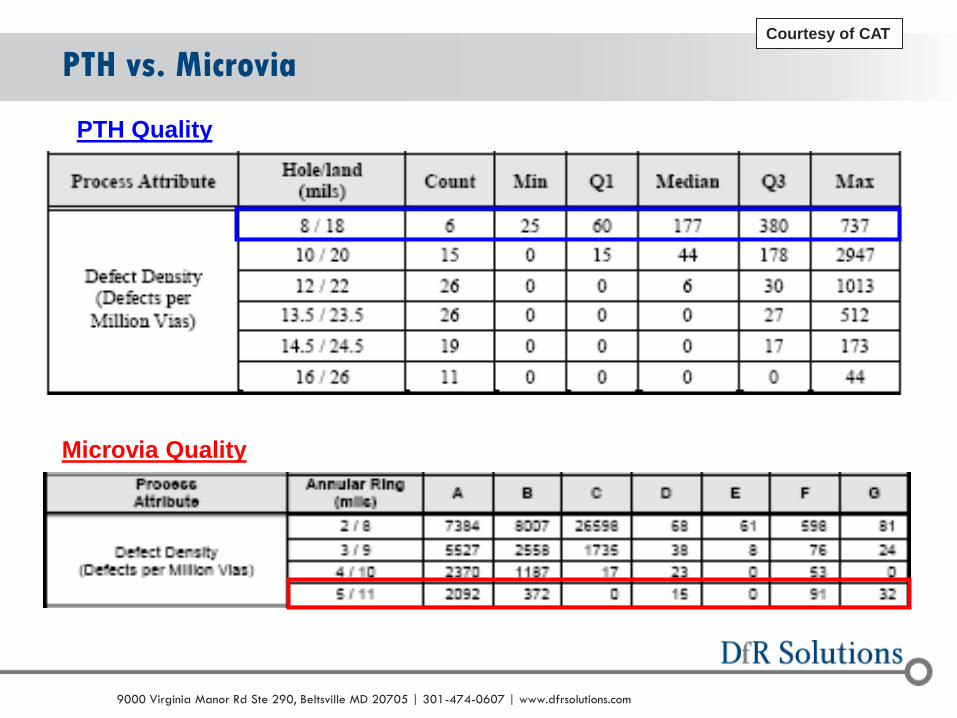
PTH vs. Microvia Courtesy of CAT
PTH Quality
Microvia Quality
© 2004 - 2007 © 2004 - 2010 9000 Virginia Manor Rd Ste 290, Beltsville MD 20705 | 301-474-0607 | www.dfrsolutions.com
o The capability of the PCB industry in regards to hole
diameter tends to segment
o Very high yield (>13.5 mil)
o High yield (10 – 13.5 mil)
o Lower yield (< 10 mil)
o If 8 mil drill diameter is required
o Consider using PCQR2 to identify a capable supplier
o Consider using interconnect stress test (IST) coupons to ensure
quality for each build
o Consider transitioning to microvias (6 mil diameter)
Summary (PTH and Microvias)

© 2004 - 2007 © 2004 - 2010 9000 Virginia Manor Rd Ste 290, Beltsville MD 20705 | 301-474-0607 | www.dfrsolutions.com
o Increasingly companies need powerful algorithms and
tools to accurately predict the probability of failure over
the lifetime of the product
o Even cell phones, with power amplifiers with high power
cycles and dissipation, can experience wearout in three
years
Physics of Failure

© 2004 - 2007 © 2004 - 2010 9000 Virginia Manor Rd Ste 290, Beltsville MD 20705 | 301-474-0607 | www.dfrsolutions.com
o Knowing the critical drivers for solder joint fatigue, we can
develop predictive models and design rules
Drivers for Thermo-Mechanical Failures
CTE of Board
Elastic Modulus (Compliance) of Board
CTE of Component
Elastic Modulus (Compliance) of Component
Length of Component
Volume of Solder
Thickness of Solder
Solder Fatigue Properties
© 2004 - 2007 © 2004 - 2010 9000 Virginia Manor Rd Ste 290, Beltsville MD 20705 | 301-474-0607 | www.dfrsolutions.com
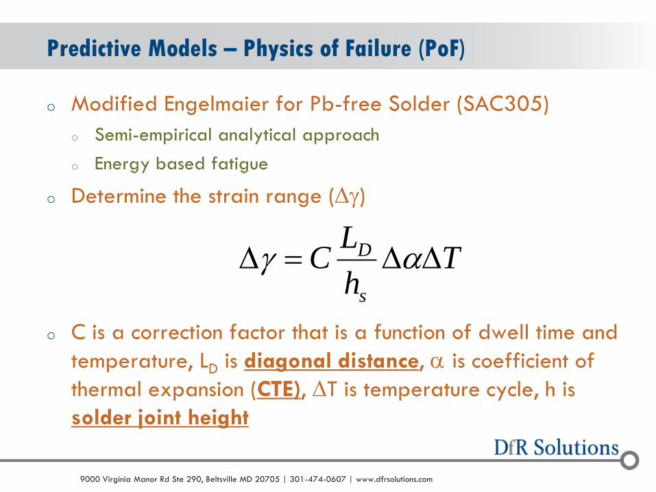
Predictive Models – Physics of Failure (PoF)
o Modified Engelmaier for Pb-free Solder (SAC305)
o Semi-empirical analytical approach
o Energy based fatigue
o Determine the strain range (Dg)
o C is a correction factor that is a function of dwell time and
temperature, LD is diagonal distance, a is coefficient of
thermal expansion (CTE), DT is temperature cycle, h is
solder joint height
Th
LC
s
D DDD ag

© 2004 - 2007 © 2004 - 2010 9000 Virginia Manor Rd Ste 290, Beltsville MD 20705 | 301-474-0607 | www.dfrsolutions.com
Predictive Models – Physics of Failure (PoF)(cont.)
o Determine the shear force applied to the solder joint
o F is shear force, L is length, E is elastic modulus, A is the area, h
is thickness, G is shear modulus, and a is edge length of bond pad
o Subscripts: 1 is component, 2 is board, s is solder joint, c is bond
pad, and b is board
o Takes into consideration foundation stiffness and both
shear and axial loads
D
aGGA
h
GA
h
AE
L
AE
LFLT
bcc
c
ss
s
9
2
221112
aa
© 2004 - 2007 © 2004 - 2010 9000 Virginia Manor Rd Ste 290, Beltsville MD 20705 | 301-474-0607 | www.dfrsolutions.com
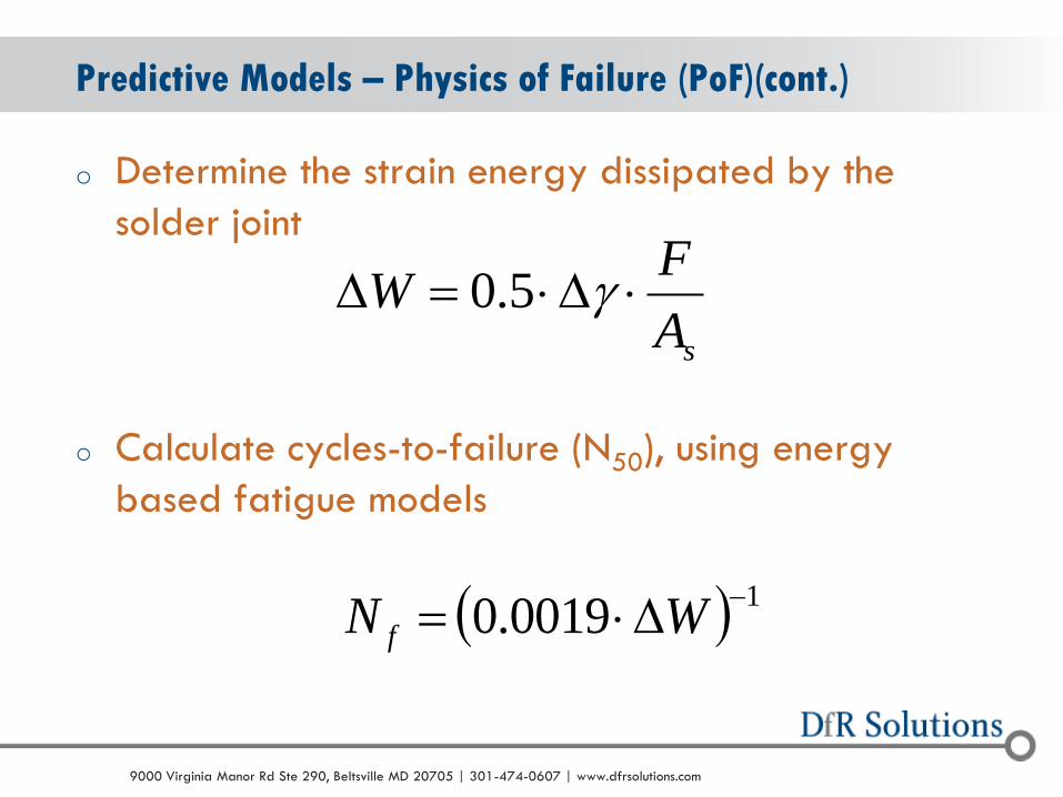
Predictive Models – Physics of Failure (PoF)(cont.)
o Determine the strain energy dissipated by the
solder joint
o Calculate cycles-to-failure (N50), using energy
based fatigue models
10019.0
D WN f
sA
FW DD g5.0

© 2004 - 2007 © 2004 - 2010 9000 Virginia Manor Rd Ste 290, Beltsville MD 20705 | 301-474-0607 | www.dfrsolutions.com
And It Works!
Model

© 2004 - 2007 © 2004 - 2010 9000 Virginia Manor Rd Ste 290, Beltsville MD 20705 | 301-474-0607 | www.dfrsolutions.com
More specific design rules requires performing a higher level
of analysis (especially for power cycling)
Thermo-Mechanical Design Rules Through Prediction
3D Sherlock Model
Thermal Analysis Results

© 2004 - 2007 © 2004 - 2010 9000 Virginia Manor Rd Ste 290, Beltsville MD 20705 | 301-474-0607 | www.dfrsolutions.com
Design Rules Through Prediction (cont.)

© 2004 - 2007 © 2004 - 2010 9000 Virginia Manor Rd Ste 290, Beltsville MD 20705 | 301-474-0607 | www.dfrsolutions.com
o Demonstrated to avionics customer that transition to Pb-free
would have a detrimental impact to product performance
o Driven by severe use environment
Benchmarking Different Materials
SnPb Assembly SAC305 Assembly

© 2004 - 2007 © 2004 - 2010 9000 Virginia Manor Rd Ste 290, Beltsville MD 20705 | 301-474-0607 | www.dfrsolutions.com
o Lighting products customer was attempting to develop a
product qualification plan
o Sherlock identified appropriate test time and test condition
based on field environment and likely failure mechanism
Developing Accurate Accelerated Life Tests (ALT)

© 2004 - 2007 © 2004 - 2010 9000 Virginia Manor Rd Ste 290, Beltsville MD 20705 | 301-474-0607 | www.dfrsolutions.com
Mechanical

© 2004 - 2007 © 2004 - 2010 9000 Virginia Manor Rd Ste 290, Beltsville MD 20705 | 301-474-0607 | www.dfrsolutions.com
o Currently no methodology
for predicting number of
shocks/drops to failure
o Assessment is go/no-go
o Based on a critical board
level strain
o Varies based on component
type and strain rate
Predicting Mechanical Shock Failures
Lcc
IPC-9704
Initially
developed by
Steinberg

© 2004 - 2007 © 2004 - 2010 9000 Virginia Manor Rd Ste 290, Beltsville MD 20705 | 301-474-0607 | www.dfrsolutions.com
o Except for really simple structures, you need finite element
analysis (FEA)
o There are techniques that use simple spring mass approximation
to predict the board deflection during a shock event
o Spring/mass models assume masses connected by
ideal weightless springs
o FEA simulations are usually transient dynamic
o DfR (Sherlock) utilizes an implicit transient dynamic simulation
(useful when solving linear/elastic)
Calculating Board Level Strain

© 2004 - 2007 © 2004 - 2010 9000 Virginia Manor Rd Ste 290, Beltsville MD 20705 | 301-474-0607 | www.dfrsolutions.com
o Shock pulse is transmitted through the mounting points into
the board
o The resulting board strains are extracted from the FEA
results and used to predict robustness under shock
conditions
Calculating Board Level Strain

© 2004 - 2007 © 2004 - 2010 9000 Virginia Manor Rd Ste 290, Beltsville MD 20705 | 301-474-0607 | www.dfrsolutions.com
CPU Card with DC/DC Converter
o 50G shock pulse
o Results in 12 mm
deflection (severe)
© 2004 - 2007 © 2004 - 2010 9000 Virginia Manor Rd Ste 290, Beltsville MD 20705 | 301-474-0607 | www.dfrsolutions.com
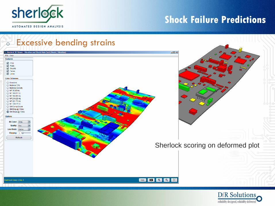
Shock Failure Predictions
o Excessive bending strains
Sherlock scoring on deformed plot

© 2004 - 2007 © 2004 - 2010 9000 Virginia Manor Rd Ste 290, Beltsville MD 20705 | 301-474-0607 | www.dfrsolutions.com
o Two additional mounting points added mid-span
o Deflection drops from 12 mm to 1.65 mm
Model Modification Shock
Still some component failures
more support is needed

© 2004 - 2007 © 2004 - 2010 9000 Virginia Manor Rd Ste 290, Beltsville MD 20705 | 301-474-0607 | www.dfrsolutions.com
o Board mounted to a chassis plate
Model Modification Shock
Presence of chassis reduces
board bending
© 2004 - 2007 © 2004 - 2010 9000 Virginia Manor Rd Ste 290, Beltsville MD 20705 | 301-474-0607 | www.dfrsolutions.com
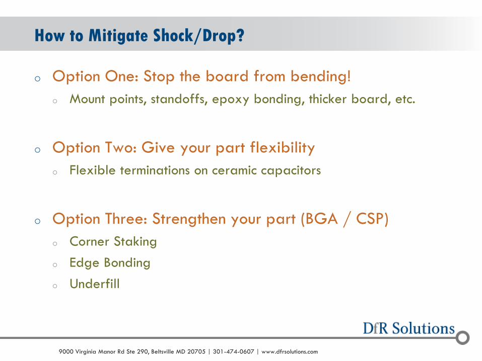
o Option One: Stop the board from bending!
o Mount points, standoffs, epoxy bonding, thicker board, etc.
o Option Two: Give your part flexibility
o Flexible terminations on ceramic capacitors
o Option Three: Strengthen your part (BGA / CSP)
o Corner Staking
o Edge Bonding
o Underfill
How to Mitigate Shock/Drop?
© 2004 - 2007 © 2004 - 2010 9000 Virginia Manor Rd Ste 290, Beltsville MD 20705 | 301-474-0607 | www.dfrsolutions.com
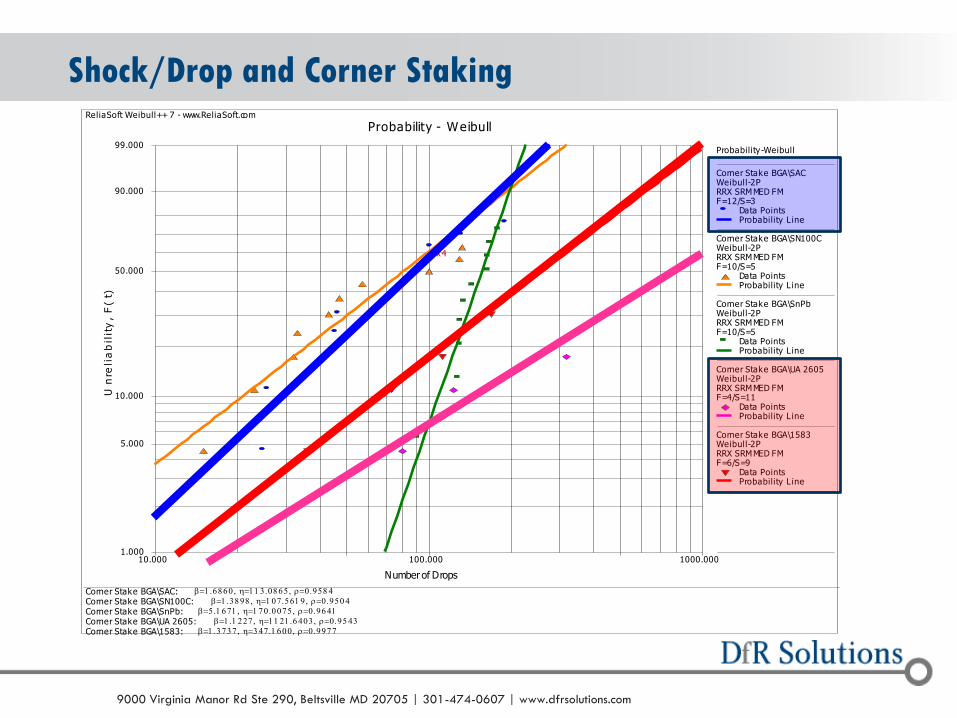
Shock/Drop and Corner Staking ReliaSoft Weibull++ 7 - www.ReliaSoft.com
Probability - Weibull
Corner Stake BGA\1583: Corner Stake BGA\UA 2605: Corner Stake BGA\SnPb: Corner Stake BGA\SN100C: Corner Stake BGA\SAC:
Number of Drops
Un
reli
ab
ilit
y,
F(
t)
10.000 1000.000100.0001.000
5.000
10.000
50.000
90.000
99.000
x 4
Probability-Weibull
Corner Stake BGA\SACWeibull-2PRRX SRM MED FMF=12/S=3
Data PointsProbability L ine
Corner Stake BGA\SN100CWeibull-2PRRX SRM MED FMF=10/S=5
Data PointsProbability L ine
Corner Stake BGA\SnPbWeibull-2PRRX SRM MED FMF=10/S=5
Data PointsProbability L ine
Corner Stake BGA\UA 2605Weibull-2PRRX SRM MED FMF=4/S=11
Data PointsProbability L ine
Corner Stake BGA\1583Weibull-2PRRX SRM MED FMF=6/S=9
Data PointsProbability L ine
Melissa KeenerDfR Solutions8/7/20123:55:11 PM

© 2004 - 2007 © 2004 - 2010 9000 Virginia Manor Rd Ste 290, Beltsville MD 20705 | 301-474-0607 | www.dfrsolutions.com
Shock/Drop and Underfill ReliaSoft Weibull++ 7 - www.ReliaSoft.com
Probability - Weibull
Underfill\BGA L3549: Underfill\SN100C: Underfill\SnPb: Underfill\SAC305:
Number of Drops
Un
reli
ab
ilit
y,
F(
t)
10.000 1000.000100.0001.000
5.000
10.000
50.000
90.000
99.000
x 4
x 15
Probability-Weibull
Underfill\SAC305Weibull-2PRRX SRM MED FMF=12/S=3
Data PointsProbability L ine
Underfill\SnPbWeibull-2PRRX SRM MED FMF=10/S=5
Data PointsProbability L ine
Underfill\SN100CWeibull-2PRRX SRM MED FMF=10/S=5
Data PointsProbability L ine
Underfill\BGA L3549Weibull-1PMLE SRM MED FMF=0/S=15
Susp PointsProbability L ine
Melissa KeenerDfR Solutions8/31/201211:20:58 AM

© 2004 - 2007 © 2004 - 2010 9000 Virginia Manor Rd Ste 290, Beltsville MD 20705 | 301-474-0607 | www.dfrsolutions.com
o Primarily affiliated with transportation
o Shipping (very short part of the life cycle)
o Automotive, trains, avionics, etc.
o Also a concern with rotating machinery (motors)
o Transportation, appliances, HVAC, pipelines
o The two environments produce two very different forms of
vibration
o Harmonic (sinusoidal) and Random
When Does Vibration Occur?
© 2004 - 2007 © 2004 - 2010 9000 Virginia Manor Rd Ste 290, Beltsville MD 20705 | 301-474-0607 | www.dfrsolutions.com
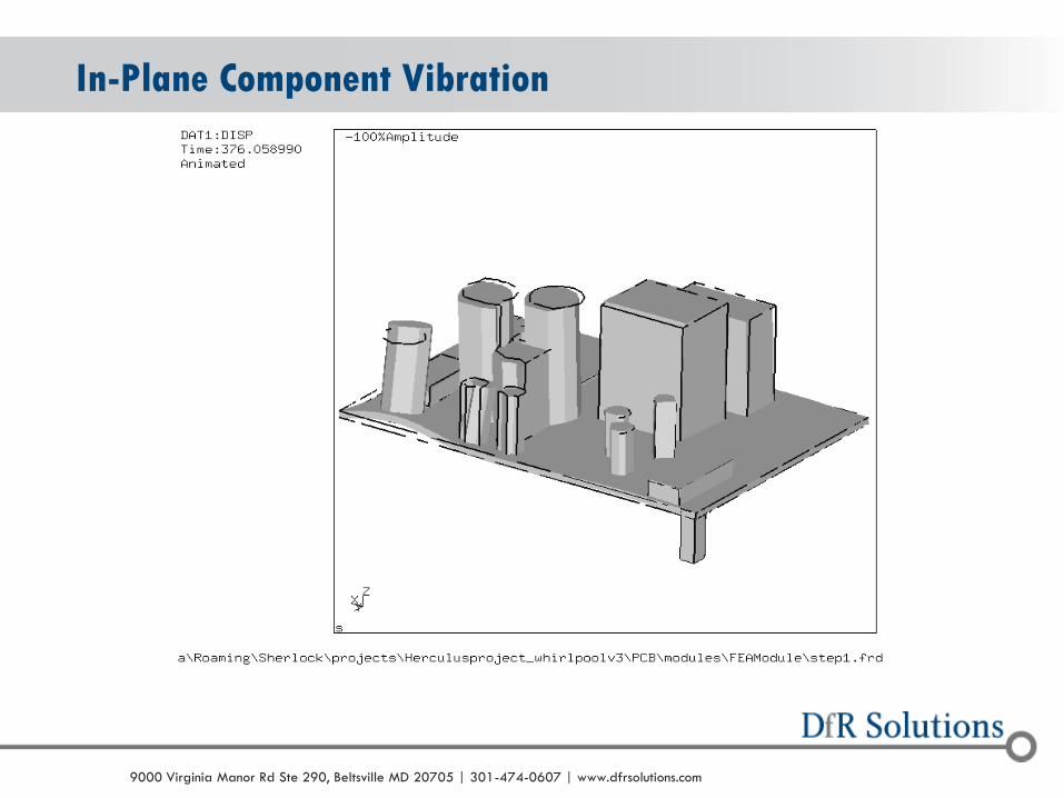
In-Plane Component Vibration

© 2004 - 2007 © 2004 - 2010 9000 Virginia Manor Rd Ste 290, Beltsville MD 20705 | 301-474-0607 | www.dfrsolutions.com
Predicting Vibration Failures (Steinberg)
20
PSD2
38.9
n
n
f
QfZ
Random
20
8.9
n
in
f
QGZ
Harmonic
Steinberg D.S. Vibration analysis for electronic equipment. John Wiley & Sons, 2000.
o The board displacement is modeled as a single degree of freedom system (spring, mass) using an estimate (or measured) of the natural frequency o Allows for calculation of
maximum deflection (Z0)
o Variables o PSD is the power spectral density (g2/Hz)
o fn is the natural frequency of the CCA
o Gin is the acceleration in g
o Q is transmissibility (assumed to be square root of natural frequency)

© 2004 - 2007 © 2004 - 2010 9000 Virginia Manor Rd Ste 290, Beltsville MD 20705 | 301-474-0607 | www.dfrsolutions.com
o Calculate critical displacement
o This is the displacement value at which the component can survive 10 to 20 million cycles (harmonic, random)
o Variables
o B is length of PCB parallel to component
o c is a component packaging constant
o 1 to 2.25
o h is PCB thickness
o r is a relative position factor
o 1.0 when component at center of PCB
o L is component length
Predicting Vibration Failures (cont.)
Lchr
BZc
00022.0
Steinberg D.S. Vibration analysis for electronic equipment.
John Wiley & Sons, 2000.
© 2004 - 2007 © 2004 - 2010 9000 Virginia Manor Rd Ste 290, Beltsville MD 20705 | 301-474-0607 | www.dfrsolutions.com
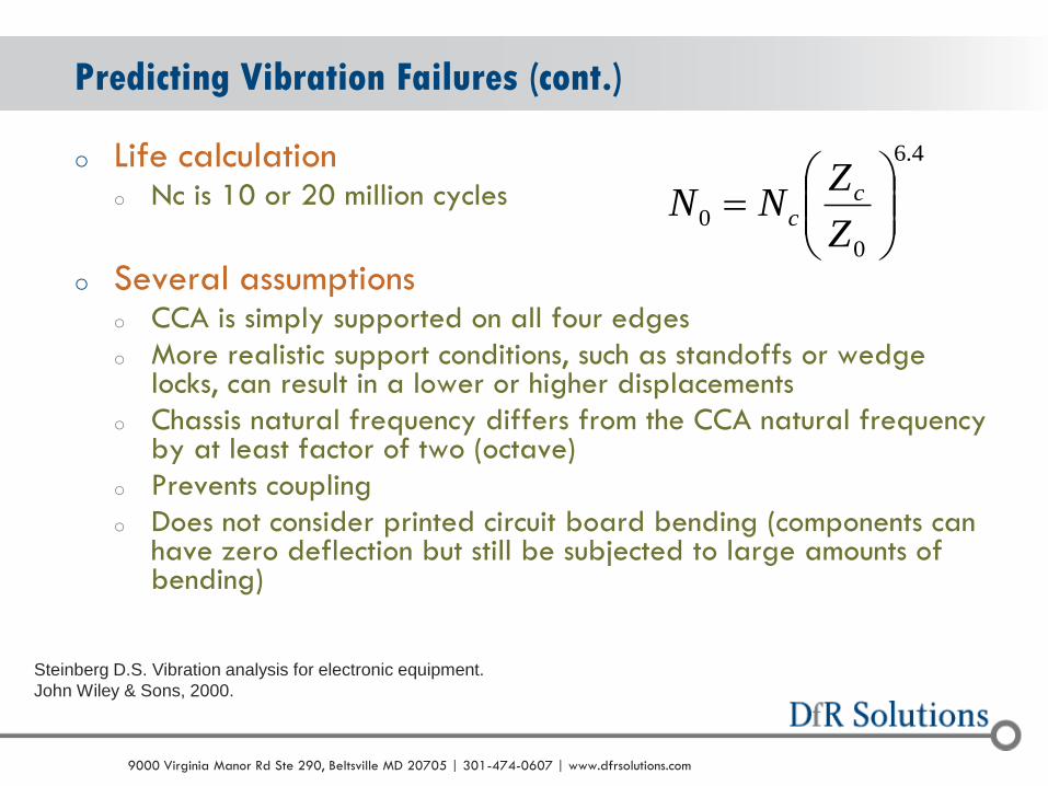
o Life calculation o Nc is 10 or 20 million cycles
o Several assumptions o CCA is simply supported on all four edges
o More realistic support conditions, such as standoffs or wedge locks, can result in a lower or higher displacements
o Chassis natural frequency differs from the CCA natural frequency by at least factor of two (octave)
o Prevents coupling
o Does not consider printed circuit board bending (components can have zero deflection but still be subjected to large amounts of bending)
Predicting Vibration Failures (cont.)
Steinberg D.S. Vibration analysis for electronic equipment.
John Wiley & Sons, 2000.
4.6
0
0
Z
ZNN c
c

© 2004 - 2007 © 2004 - 2010 9000 Virginia Manor Rd Ste 290, Beltsville MD 20705 | 301-474-0607 | www.dfrsolutions.com
o Finite Element Analysis can be used to capture more
complex geometries, loadings and boundary conditions
o
FEA Based Vibration Predictions

© 2004 - 2007 © 2004 - 2010 9000 Virginia Manor Rd Ste 290, Beltsville MD 20705 | 301-474-0607 | www.dfrsolutions.com
Example: Mezzanine and Daughter cards
FEA Based Vibration Predictions (cont.)
Sherlock 3.0
Sherlock 3.0

© 2004 - 2007 © 2004 - 2010 9000 Virginia Manor Rd Ste 290, Beltsville MD 20705 | 301-474-0607 | www.dfrsolutions.com
o Loading can be applied to the model directly from the specification
o Vibration is applied to the structure through the standoffs/mount points
FEA Modeling Loads

© 2004 - 2007 © 2004 - 2010 9000 Virginia Manor Rd Ste 290, Beltsville MD 20705 | 301-474-0607 | www.dfrsolutions.com
o Determining the response of the structure to a vibration load is commonly done using a Modal Dynamic Analysis o It is necessary to do a modal analysis before conducting this analysis
o Determines the eigenvalues and eigenmodes (natural frequencies)
o Calculates the stiffness and mass matrices
FEA Vibration Simulation

© 2004 - 2007 © 2004 - 2010 9000 Virginia Manor Rd Ste 290, Beltsville MD 20705 | 301-474-0607 | www.dfrsolutions.com
o During vibration the board strain is proportional to the solder or lead strains and therefore can be used to make time to failure predictions
o This requires converting the cycles to failure displacement equations (Steinberg) to use strain
o The strain for the components is now pulled from the FEA results
o The critical strain for the package types is a function of package style, size, lead geometry
FEA Failure Prediction
n
ccNN
0
0
Sherlock 3.0
Lcc
ζ is analogous to 0.00022B but modified
for strain
c is a component packaging function
L is component length

© 2004 - 2007 © 2004 - 2010 9000 Virginia Manor Rd Ste 290, Beltsville MD 20705 | 301-474-0607 | www.dfrsolutions.com
o Step 1: Don’t paint yourself into corner too early in the design process
o Step 2: Be aware of ALL requirements
o Step 3: Try to perform concurrent engineering
o Step 4: Use a design check list (don’t rely on tests to develop a robust design) o Part selection
o Derating
o Power Stability
o ESD
o EMI / EMC
o Design for Manufacturability / Testability / Environment
o Components that wearout
Summary of Best in Class DfR