Embed Size (px)
Citation preview

DOCTORA L T H E S I S
Luleå University of TechnologyDepartment of Applied Physics and Mechanical Engineering
Division of Functional Product Development
2007:59|: 02-5|: - -- 07 ⁄59 --
2007:59
Design for manufacturing Methods and applications
using knowledge engineering
Marcus Sandberg


Design for manufacturing Methods and applications
using knowledge engineering
Marcus Sandberg
November 2007
Luleå University of Technology Department of Applied Physics and Mechanical Engineering
Division of Functional Product Development SE-971 87 Luleå, Sweden [email protected]
This academic thesis, with due permission by the Board of the Faculty of Engineering at Luleå University of Technology, will be defended in public at Luleå University of Technology in room E246, December 19, 2007 at 9.00 a.m.
Opponent at public defence: Professor Johan Malmqvist, Chalmers, Gothenburg, Sweden.


To Sara, Miriam and Jakob


Preface
This research has been conducted at the Division of Computer Aided Design and the Division of Functional Product Development at Luleå University of Technology. Industrial partners have been Volvo Aero, Saab Automobile AB both at Trollhättan and Moelven Byggmodul AB, at Sandsjöfors. VINNOVA provided funding through the programmes Tillverkningsindustrins produktframtagning, Lean wood engineering and the VINN Excellence Center Faste Laboratory – Center for Functional Product Innovation, which is greatly acknowledged. It has been a pleasant journey, though full of surprises, pitfalls and challenges mixed with semi-structured moments of eureka. I am thus grateful to a bunch of people in and out the engineering design swamp, because without you it simply couldn’t have been done. So, I have the honour of acknowledging the following people:
Tobias Larsson, my advisor, for having a good time, for all the important discussions, for offering exciting research opportunities and for your never-ending energy and positive mindset! You’re great! Lennart Karlsson, for swiftly providing me an opportunity to do research studies. Ola Isaksson, Volvo Aero, for your good advice and sharp perception. Patrik Boart, Volvo Aero, for your hospitality and great and loud discussions. Henrik Nergård, for being such a nice guy and for a good time in E210b – don’t get me wrong man . Lars Stehn and Helena Johnsson and the rest of the timber structures research group, for letting me play with you – you are such a nice bunch of people. All my colleagues at the Division of Functional Product Development for making the working environment so enjoyable, relaxed and full of uniue research energy. A special acknowledgement to Åsa Ericson for being a nice person and for all our amusing chats, though I have to wait until you check in to the elderly home until I can beat you at knowledge about research methods, or even then.
Also, I’d like to thank my friends for creating a nice source of distraction, full of fun, laughs, screams, and food smear of you and your wonderful children .
Thanks to all musicians and composers that I have had the groovy and sonorous pleasure to listen to during my work.
I wish to express a special gratitude to Sara, Miriam and Jakob for all the wonderful moments, and especially to Sara for all her support and faith in me.
Finally thanks to you, dear reader, for taking part of my work. Enjoy the reading!
Marcus Sandberg Luleå, November 2007


Abstract
As companies strive to develop artefacts intended for services instead of traditional sell-off, new challenges in the product development process arise to promote continuous improvement and increasing market profits. This creates a focus on product life-cycle components as companies then make life-cycle commitments, where they are responsible for the function availability during the extent of the life-cycle, i.e. functional products. One of these life-cycle components is manufacturing; therefore, companies search for new approaches of success during manufacturability evaluation already in engineering design. Efforts have been done to support early engineering design, as this phase sets constraints and opportunities for manufacturing. These efforts have turned into design for manufacturing methods and guidelines.
A further step to improve the life-cycle focus during early engineering design is to reuse results and use experience from earlier projects. However, because results and experiences created during project work are often not documented for reuse, only remembered by some people, there is a need for design support. Knowledge engineering (KE) is a methodology for creating knowledge-based systems, e.g. systems that enable reuse of earlier results and make available both explicit and tacit corporate knowledge, enabling the automated generation and evaluation of new engineering design solutions during early product development. There are a variety of KE-approaches, such as knowledge-based engineering, case-based reasoning and programming, which have been used in research to develop design for manufacturing methods and applications. There are, however, opportunities for research where several approaches and their interdependencies, to create a transparent picture of how KE can be used to support engineering design, are investigated. The aim of the research presented in this thesis is to create new methods for design for manufacturing, by using several approaches of KE, and find the beneficial and less beneficial aspects of these methods in comparison to each other and earlier research.
This thesis presents methods and applications for design for manufacturing using KE. KE has been employed in several ways, namely rule-based, rule-, programming- and finite element analysis (FEA)-based, and rule- and plan-based, which are tested and compared with each other. Results show that KE can be used to generate information about manufacturing in several ways. The rule-based way is suitable for supporting life-cycle commitments, as engineering design and manufacturing can be integrated with maintenance and performance predictions during early engineering design, though limited to the firing of production rules. The rule-, programming- and FEA-based way can be used to integrate computer-aided design tools and virtual manufacturing for non-linear stress and displacement analysis. This way may also bridge the gap between engineering designers and computational experts, even though this way requires a larger effort to program than the rule-based. The rule- and plan-based way can enable design for manufacturing in two fashions – based on earlier manufacturing plans and based on rules. Because earlier manufacturing plans, together with programming algorithms, can handle knowledge that may be more intricate to capture as rules, as opposed to the time demanding routine work that is often automated by means of rules, several opportunities for designing for manufacturing exist.
Keywords: Engineering design, design for manufacturing, knowledge engineering, design automation, functional product development and product life-cycle.


Sammanfattning
Företag strävar efter utveckling av fysiska produkter som kan säljas som tjänster istället för på traditionellt sätt då kunden betalar för produkten och därmed blir ägare. Därför uppstår nya utmaningar för produktutvecklande företag som vill behålla en stark marknadsställning. Eftersom denna tjänsteprodukt, här benämnd funktionell produkt, innebär ett åtagande för företaget under hela livscykeln, där företaget ansvarar för produkten ifrån utvecklandet av den tills att den skrotas och återvinns, skapas fokus på hur den fysiska produkten ska utvecklas för företagets och kundens bästa under produktens livscykel. Därför behöver utveckling av funktionella produkter ett livscykelperspektiv, dvs. att livscykeln beaktas vid konstruktion. En del av livscykeln är tillverkningen varför företag letar efter nya sätt att utvärdera hur tillverkbar produkten är redan vid tidig konstruktion, eftersom tidig konstruktion bestämmer begränsningar och möjligheter för tillverkning. Metoder och handböcker för att konstruera för tillverkbarhet har därför tagits fram för att underlätta anpassningen av konstruktionen till produktionsanläggning.
Ett ytterligare steg mot förbättrade arbetssätt med livscykelperspektiv vid tidig konstruktion är att återanvända resultat och använda erfarenhet från tidigare projekt. Men eftersom resultat och erfarenheter från projekt sällan dokumenteras på ett sätt som underlättar återanvändning eller stannar i huvudena på produktutvecklare, t ex konstruktörer och tillverkningsingenjörer, finns ett behov för hjälpmedel för återanvändning. Kunskapsdrivet ingenjörsarbete (KI) är en metodik för att återanvända tidigare resultat och göra erfarenheter tillgängliga genom att möjliggöra arbetssätt för automatiserad produktdefinition och utvärdering vid tidig konstruktion. Det finns möjligheter för forskning där KI används på flera sätt och där dessa sätts kopplingar undersöks för att ge en klar bild om hur KI kan stödja konstruktion. Därför är målet med denna avhandling att använda KI för att skapa metoder för att konstruera för tillverkbarhet och utvärdera fördelaktiga och mindre fördelaktiga egenskaper med dessa metoder jämfört med varandra och tidigare forskning.
I denna avhandling presenteras metoder och applikationer för konstruktion för tillverkbarhet baserade på KI. Metoderna är baserade på KI på följande sätt: regelbaserat, regel-, programmerings- och finit element analys (FEA)-baserat, och regel- och planbaserat. Resultatet visar att KI kan användas för att generera information om tillverkning på flera sätt. Det regelbaserade sättet är lämpligt för att stödja åtagande, där hela livscykeln ansvaras för, eftersom konstruktion och tillverkningsutvärdering kan integreras med utvärdering av underhåll och prestanda, även om detta sätt begränsas av reglernas omfattning. Det sätt som baseras på regler, programmering, och FEA kan användas för att integrera program för datorstödd konstruktion med program för simulering av spänning och töjningar i produkten som orsakas av tillverkningsoperationer. Detta sätt kräver dock en mer omfattande programmeringsinsats jämfört med det regelbaserade sättet. Det regel- och planbaserade sättet kan möjliggöra konstruktion för tillverkbarhet på två olika sätt, dels baserat på tidigare tillverkningsplaner och dels baserat på regler. Eftersom tidigare tillverkningsplaner tillsammans med programmeringsalgoritmer kan hantera kunskaper som kan vara svårare att definiera som regler, än det tidskrävande rutinarbetet som oftast automatiseras med regler, finns det flera möjligheter att förbättra konstruktionen för tillverkbarhet.
Nyckelord: Konstruktion, konstruktion för tillverkbarhet, kunskapsdrivet ingenjörsarbete, automatiserad konstruktion, funktionell produktutveckling och produktlivscykel.


List of abbreviations
CAD Computer-aided design CAM Computer-aided manufacturing CBR Case-based reasoning CE Concurrent engineering DFM Design for manufacturing ES Expert systems FEA Finite element analysis FPD Functional product development GUI Graphical user interface IT Information technology KE Knowledge engineering KBE Knowledge-based engineering KBS Knowledge-based systems PDM Product data management PLC Product life-cycle PLM Product life-cycle management TORL Total offer readiness level


Thesis
This thesis comprises an introductory part and the following appended papers:
Paper A Sandberg M., Boart P. and Larsson T., Functional product life-cycle simulation model for cost estimation in conceptual design of jet engine components, Journal of Concurrent Engineering: Research and Applications Vol. 13:4, 2005.
Paper B Sandberg, M., Åström, P., Larsson, T. and Näsström, M., A design tool integrating CAD and virtual manufacturing for distortion assessment, Proceedings of the International Conference on Engineering Design, August 15-18 2005, Melbourne, Australia.
Paper C Sandberg M. and Larsson T., Automating redesign of sheet-metal parts in automotive industry using KBE and CBR, Proceedings of the ASME International Design Engineering Technical Conferences & Computers and Information in Engineering Conference, 10-13 September, 2006, Philadelphia, Pennsylvania, USA.
Paper D Sandberg M. and Marefat M. M., Combining knowledge-based engineering and case-based reasoning for design and manufacturing iteration, Proceedings of the 4th International Conference on Manufacturing Research, 5-7 September 2006, Liverpool, UK.
Paper E Sandberg M., Manufacturability evaluation in early design: On the dependency of business commitment, Proceedings of the 5th International Conference on Manufacturing Research, 11-13 September 2007, Leicester, UK.
Paper F Sandberg M., Johnsson H. and Larsson T., Knowledge-based engineering in construction: The prefabricated timber housing case, Submitted to Journal of Information Technology in Construction.
The following paper is related to the thesis but not included:
Boart, P., Nergård, H., Sandberg, M. and Larsson, T., A multidisciplinary design tool with downstream processes embedded for conceptual design and evaluation, Proceedings of the International Conference on Engineering Design, August 15-18 2005, Melbourne, Australia.

Contents
1 INTRODUCTION ..........................................................................1
1.1 Background............................................................................................................11.2 Motivation .............................................................................................................21.3 Aim and scope........................................................................................................31.4 Reader’s guide .......................................................................................................3
2 RESEARCH APPROACH ...............................................................5
2.1 Literature review....................................................................................................52.2 Empirical data collection ........................................................................................6
2.2.1 Documentation files and participatory observations .........................................62.2.2 Interviewing and workshops ...........................................................................62.2.3 Analysis of collected data .................................................................................7
2.3 Idea proposal ..........................................................................................................72.4 Concept development ............................................................................................72.5 Concept analysis .....................................................................................................72.6 Research conclusion...............................................................................................8
3 KNOWLEDGE DOMAINS ..............................................................9
3.1 Product development .............................................................................................93.1.1 Integrated product development and concurrent engineering ........................103.1.2 Functional product development...................................................................103.1.3 Engineering design........................................................................................10
3.2 Product life-cycle analysis .....................................................................................113.2.1 Product data management and product life-cycle management......................123.2.2 Cost estimation .............................................................................................12
3.3 Design for manufacturing .....................................................................................123.4 Virtual manufacturing...........................................................................................13
3.4.1 Computer-aided manufacturing ....................................................................133.4.2 Simulations of manufacturing processes using finite element analysis..............14
3.5 Knowledge engineering........................................................................................143.5.1 Knowledge-based engineering.......................................................................143.5.2 Expert systems...............................................................................................153.5.3 Case-based reasoning.....................................................................................153.5.4 Combining rule-based approaches and case-based reasoning..........................16
3.6 Design for manufacturing using knowledge engineering.......................................16
4 RESEARCH OPPORTUNITIES AND COMPANY ISSUES ............. 18
4.1 Research opportunities.........................................................................................184.2 Company issues....................................................................................................18
4.2.1 Company introduction and project relation...................................................184.2.2 Found issues ..................................................................................................19
5 DESIGN FOR MANUFACTURING: METHODS AND APPLICATIONS USING KNOWLEDGE ENGINEERING ..................... 21
5.1 Manufacturability evaluation during functional product development...................215.1.1 Multidisciplinary method ..............................................................................215.1.2 Total offer readiness level ..............................................................................23

5.2 Integration of design and manufacturing simulation..............................................265.3 Automatic redesign and manufacturability iteration ..............................................285.4 Design and manufacturing evaluation for construction..........................................29
6 SUMMARY OF APPENDED PAPERS ........................................... 31
6.1 Paper A ................................................................................................................316.2 Paper B ................................................................................................................326.3 Paper C................................................................................................................326.4 Paper D................................................................................................................336.5 Paper E ................................................................................................................346.6 Paper F.................................................................................................................34
7 DISCUSSION ............................................................................... 36
7.1 Rule-based...........................................................................................................377.1.1 Knowledge modelling ...................................................................................377.1.2 Multidisciplinary method for manufacturability evaluation of functional products .....................................................................................................................377.1.3 Design and manufacturing evaluation in construction....................................37
7.2 Rule-, programming- and FEA-based ..................................................................387.2.1 Knowledge modelling ...................................................................................387.2.2 Integration of design and manufacturing simulation.......................................38
7.3 Rule- and plan-based ...........................................................................................397.3.1 Knowledge modelling ...................................................................................397.3.2 Automated redesign and manufacturability iteration ......................................39
7.4 Manufacturability evaluation and business commitment........................................397.5 TORL .................................................................................................................407.6 Reflections on assessing the impact of the research results.....................................40
8 CONCLUSION............................................................................. 42
8.1 Scientific and industrial contribution ....................................................................428.2 Suggestions for future research..............................................................................43
8.2.1 Maintenance .................................................................................................438.2.2 Organisational ...............................................................................................44
REFERENCES.................................................................................... 45
APPENDED PAPERS


Marcus Sandberg, Design for manufacturing: methods and applications using knowledge engineering
1
1 Introduction This chapter introduces the challenges of functional product development and product life-cycle analysis and the opportunities for design for manufacturing and knowledge engineering to set the scene for the research presented in this thesis.
1.1 BackgroundOn the competitive global markets of today, companies strive to increase profits by reducing development costs and increasing quality. To be in the front line of business success, there is little room for traditional “over the wall” work, where several company departments work separated from each other. Instead integrated product development (Andreassen and Hein, 1987) and concurrent engineering (Prasad, 1997) are available to ensure that as many product life-cycle aspects as possible are considered by creating multidisciplinary teams that work in parallel during development. The product life-cycle includes everything from perceived customer needs through engineering design, manufacturing, maintenance, scrapping and recycling.
The focus on the product life-cycle becomes even stronger because of the trend where companies aim for service-oriented products where companies supply a function rather than selling off the hardware, i.e. the physical artefact. These types of business contracts may make the company the product owner and therefore responsible for providing the function during the product life-cycle. Functional product development is the aim when hardware is developed to suit such a function (Alonso-Rasgado et al., 2004). As companies make life-cycle commitments, which are often long (Ericson, 2006), the focus on the product life-cycle is motivated.
Early engineering design, i.e. conceptual and embodiment design, is a phase of the product development process that impacts cost. Early engineering design decides the opportunities (see Figure 1) and limitations of the later phases, since the developed product geometry, for instance, affects how well the manufacturing, assembly, maintenance, and so forth will be conducted. The phase itself is not costly compared to, for instance, the cost of manufacturing. Rather, it is the costs disposed of by early engineering design, and often seen later when they occur during, e.g. manufacturing, that can be high and often too high (Barton et al., 2001). Priest and Sánchez (2001) state that around 40% of all product quality problems are due to poor design. When a problem is found later, e.g. during detailed design or manufacturing, going back to early engineering design and make changes is costly. Therefore, it is important to account for the product life-cycle already during early engineering design.

Marcus Sandberg, Design for manufacturing: methods and applications using knowledge engineering
2
One way to account for the product life-cycle is by means of engineering design support tools that can contribute with information for decision making. There is, however, a tendency that the earlier in the design process, the fewer engineering design support tools are available, often due to a lack of knowledge of design requirements and constraints (Wang et al., 2002); see Figure 1. One important part to consider for the product life-cycle is to create products that conform to the manufacturing facilities, i.e. developing an engineering design that can be manufactured by the machines and the crew of the production plant and preferably at the lowest cost. This is often referred to as design for manufacturing and several methods and guidelines for designing for manufacturing have been developed, e.g. (Boothroyd et al., 2001; Bralla, 1999; Priest and Sánchez, 2001). Such methods describe general strategies for how engineering design should be conducted to minimise problems during the most common manufacturing operations.
Figure 1. Availability of support tools during engineering design and production, (IMTI, 2000).
1.2 Motivation General design for manufacturing strategies can help companies develop products that are feasible to manufacture, but to go further towards increased effectiveness, there is an opportunity to reuse results and use corporate knowledge gained from earlier projects and make this available as support tools during early engineering design. Results and corporate knowledge tend to stay within the group instead of being documented in a way that promotes reuse. In doing so, development performance is affected by staff turnover, which occurs when projects are finished, or by the often time demanding search for the right document that contains the right information. This issue increases when considering the extensiveness of information needed during functional product development.
Knowledge engineering (KE) is a methodology for the creation of knowledge-based systems using methods such as knowledge-based engineering, case-based reasoning and

Marcus Sandberg, Design for manufacturing: methods and applications using knowledge engineering
3
expert systems to promote the reuse of earlier results and make available corporate knowledge of later processes and thus aid the generation and evaluation of new engineering design solutions during early product development. The concept of reusing earlier solutions is found in human reasoning, since humans tend to think of solutions to similar problems when confronted with a new problem.
There are several research methods and computer applications for the reuse and enabling of corporate knowledge during design for manufacturing activities, e.g. (Ramana and Rao, 2005; Shehab and Abdalla, 2001; Venkatachalam, 1994). However, it is still an opportunity to explain how to adopt KE methods and applications by comparing different KE approaches, for design for manufacturing, in terms of beneficial and less beneficial properties. Therefore, further studies are needed.
1.3 Aim and scope The aim of the research presented in this thesis is to create new methods for design for manufacturing, by using several approaches of KE, and find the beneficial and less beneficial aspects of these methods in comparison to each other and earlier research. The scope of the research is to develop methods within the projects of this thesis work in the fields of mechanical and structural engineering design. Focus is on embodiment design and evaluation of mature products, i.e. products that can be developed by creating variants of recent products. Evaluation concentrates on product conformance with manufacturing operations, e.g. machining and sheet metal stamping, rather than assembly. Within the scope is to have a product life-cycle view during manufacturability evaluation, i.e. also including other activities such as performance development and maintenance besides manufacturing operations. A research question has been formulated as:
How to use knowledge engineering to enhance manufacturability evaluation during early design when having a life-cycle view?
This question, together with the aim and the scope, guides the research described in this thesis.
1.4 Reader’s guide This thesis comprise of an introductory part and six appended papers. The introductory part comprise of eight chapters with the contents outlined below.
Chapter 1 introduces this thesis by zooming in from the broad background onto the scope of this research.
Chapter 2 presents the research approach used during the thesis work.
Chapter 3 introduces the knowledge domains coupled to this research by presenting research within mainly product development, design for manufacturing and knowledge engineering.

Marcus Sandberg, Design for manufacturing: methods and applications using knowledge engineering
4
Chapter 4 presents the found research opportunities and issues from collaborating research project companies. The companies are also briefly introduced.
Chapter 5 presents the proposed methods and applications.
Chapter 6 summarises the appended papers regarding contents, relation to the thesis and how the work was divided between the authors.
Chapter 7 discusses the research contributions in relation to the research question and earlier research. Some reflections of the impact of the research results are also given.
Chapter 8 concludes the contribution of this work with scientific and industrial contributions. Suggestions of future research are also given.

Marcus Sandberg, Design for manufacturing: methods and applications using knowledge engineering
5
2 Research approach Words or numbers, an understanding or statistical results, qualitative or quantitative research - that is the question, though some argue that there is no end in itself to draw a sharp distinction between qualitative and quantitative research (Silverman, 2005). This research has been conducted using a qualitative approach.
This chapter describes the method used in each project. An overview of this method is initially given, shown in Figure 2, followed by a description of each part. Literaturereview implies finding research opportunities by reading reference literature and discussing topics with colleagues. Empirical data collection involves finding issues, aspects and problems at the collaborating companies from the research projects. Idea proposalincludes generating ideas to address both research and industry opportunities within the limitations of the research question. Concept development involves developing the idea into a concept, both on a research level and an application level. Concept analysis implies that the concept is evaluated in terms of scientific and industrial benefit by investigating how the research question is answered and comparing it with the reference literature and evaluating the application together with the industry. The research conclusions are drawn based on the concept analysis and research results are published.
Empirical data collection
Literature review
Idea proposal
Concept development
Concept analysis
Research conclusions
timeFigure 2. Overview of the research method used in each project.
2.1 Literature review Literature review implies studying the published work, e.g. papers and books, within the research field to gain an understanding of the problem areas and identify research
Marcus Sandberg, Design for manufacturing: methods and applications using knowledge engineering
6
opportunities. The literature is analysed and compared, to focus in on a problem of interest to address in the PhD (Doctor of Philosophy) studies. The literature review has been limited to searching published work written in English and Swedish. Internet sources, such as Engineering Village1 and Google™ Scholar2, and the library at Luleå University of Technology3, where an extensive set of global publications are available through the Internet, have been searched.
2.2 Empirical data collection Empirical data collection aims to find information that can lead to the identification of company issues and interest areas to be addressed in the research. Because the literature review is done in parallel with empirical data collection, there is a balance of finding research opportunities with an industry potential. When it comes to exploring, much collected information and impressions have to be interpreted. Although hermeneutics represent the science of interpreting, the collected data has been interpreted based on the experience gained during the PhD studies. Knowing that there is an aim for being objective rather than subjective, especially in quantitative research, being subjective has to simply be accepted when interpreting. Therefore, it is vital to reflect upon what impact an individual’s background, which has formed his or her standards and set of values, has on the interpretation. A more constructionistic (Silverman, 2005) approach than emotionalistic was used, as focus was on what the interviewees do in their work instead of how the interviewees feel. The following describes the collection of documentation files and the act of participatory observations, the interviews and workshops, and finally, the analysis of the collected data.
2.2.1 Documentation files and participatory observations During the projects, the companies handed over a number of documentation files, e.g. PowerPoint, Excel, Word, PDF, solid models and finite element models, often upon requests. The explicit files were chosen by the companies based on enquiries, e.g. “Iwould like to see drawings of volume elements with different stairs” or “I would like to see design instructions for bracket design”.
Participatory observations (Savage, 2000), e.g. talking to people while observing, were done when visiting the companies, being guided through design and production facilities, and walking around alone. Observations during discussions at the companies or at Luleå University of Technology also took place, listening to when the company representatives describe their views on certain issues. These observations were noted on paper or in a laptop for analysis purpose.
2.2.2 Interviewing and workshops Interviews were performed to find issues and interests to address in the research, acquire knowledge for demonstrator development (see section 2.4) and find out how companies do engineering design work. Interviews were mostly semi-structured and open focused. According to Lantz (1993) the questions in semi-structured interviews follow a specific order and have open and predefined answers, whereas in open focused
1 www.engineeringvillage2.org, last accessed: 2007-11-02 2 scholar.google.se, last accessed: 2007-11-02 3 www.ltu.se/depts/lib/index-en.shtml, last accessed: 2007-11-02

Marcus Sandberg, Design for manufacturing: methods and applications using knowledge engineering
7
interviews the respondent deepens himself/herself into what the interviewer finds interesting without a specific order. All interviews were recorded and transcribed. Pre-booked interviews were semi-structured, i.e. questions were written down, and conducted. Open focused interviews occurred in mainly unplanned meetings. Sometimes, the semi-structured interviews became freer and more open focused when an unplanned and interesting issue came up.
Workshops following the future workshop model, intended for software development (Kensing and Madsen, 1991), were conducted to find issues and ideas to address the issues. The future workshop model contains three phases: the problem phase, where all problems and issues coupled to the workshop topic are described, the fantasy phase,where ideas are brainstormed to approach the problems and issues, if resources, e.g. time and money, are unlimited, and the realisation phase, where feasible ideas are chosen for further development. All workshops were recorded and transcribed.
2.2.3 Analysis of collected data The collected interview data was transcribed into text and read through and reflected upon both on an overarching and a detailed level. Notes were made to mark the most interesting findings. For these findings the formulation of the questions was evaluated to find out if the answers were biased by the questions. The validity of the collected data was evaluated through discussions with the company and colleagues and by reflections of the author.
2.3 Idea proposal Idea proposal is a creative activity where the selected research topics and industry issues are addressed. Often ideas were already forming during the literature review and empirical data collection and could now be synthesised further. Although beneficial to define the problem before approaching it, it is sometimes useful to suggest and analyse an idea to better understand the problem. This phenomenon is sometimes referred to as handling the wicked problem (Rittel and Webber, 1973).
2.4 Concept development During concept development, the generated ideas are transformed into a concept. This concept is then developed in detail. The concept is developed concurrently at a research level, i.e. a level presumed to contribute to the research field, and an application level, i.e. a level that can be used to demonstrate parts of the research idea to the industry and assess beneficial and less beneficial properties of the research idea.
In this thesis the application level represents a computer application that is ultimately implemented in software at the company and demonstrates the research idea to the industry, referred to as a demonstrator. To create a computer application in a timely manner, a limited part of the proposed idea needs to be chosen and used in an industry scenario.
2.5 Concept analysis The detailed concept is evaluated for its scientific benefit by investigating how the research question is answered along with comparing it with the reference literature.
Marcus Sandberg, Design for manufacturing: methods and applications using knowledge engineering
8
The industrial benefit is analysed, in a qualitative manner, by involving industry partners to test and discuss the application and revisiting the issues found during empirical data collection. This is done by creating and evaluating scenarios that resemble the partner company environment to look at the concept from different angles. A generalisation of the results to suit a variety of application areas, e.g. different companies or industries, is strived for and developed by discussing issues to find the pros and cons of the developed concept. Thus concept analysis proves parts of the detailed concept and identifies other parts that need to be further studied.
2.6 Research conclusion The research conclusions are drawn based on the concept analysis, and writing scientific papers and conference proceedings are ways to publish the research results. These conclusions are used as guidelines when embarking upon new projects.

Marcus Sandberg, Design for manufacturing: methods and applications using knowledge engineering
9
3 Knowledge domains This chapter describes the literature from the knowledge domains that this thesis is based on. The overarching area of product development is introduced to explain the main process and exemplify some key trends. Product life-cycle analysis, an area to predict the impact of engineering design decisions on later product development activities, follows. Design for manufacturing, i.e. methods that aim to ensure that the product can be manufactured at a feasible cost, is presented followed by the computer-based area of virtual manufacturing for simulating manufacturing operations. Knowledge engineering, a method to reuse earlier results and make information available by automating and structuring engineering design work, is also described. The chapter ends with some examples of methods for design for manufacturing using knowledge engineering.
3.1 Product development According to Ulrich and Eppinger (2004) p. 12:
“A product development process is the sequence of steps or activities which an enterprise employs to conceive design and commercialize a product.”
Figure 3 depicts the sequence of steps of a product development process where important manufacturing constraints and considerations are outlined as feedback arrows. Product development processes are sometimes described without the manufacture and sales and support phases. This thesis has, however, adopted the description outlined in Figure 3.
Determination of customerrequirements
Productdesign
specification
Initiation of concept
solutions to the design problem
Selection of the best concept
for furtherdevelopment
Embodimentdesign
Detail design of thechosen concept, andpreparation of full
manufacturingdescriptions
Manufacture Sales and support
Detail consideration
Preliminary analysis
Manufacturing constraints
Manufacturing considerations
Perceptions of customer needs
Figure 3. A product development process, (Wright, 1998).
This section describes integrated product development and concurrent engineering, i.e. methods to work in parallel in cross functional teams throughout the product

Marcus Sandberg, Design for manufacturing: methods and applications using knowledge engineering
10
development process, followed by literature of functional product development. Engineering design, the first six phases of Figure 3, is finally described.
3.1.1 Integrated product development and concurrent engineering The fact that some companies still work traditionally in a function based, sequential manner, where the product is like a relay-race baton shifted from design to manufacturing, has triggered the development of methods to increase in-firm collaboration by integrating company functions into a whole (Andreassen and Hein, 1987). Methods that focus more on how to conduct engineering activities, such as design and production planning in parallel and concurrently in concurrent engineering (CE), have also been suggested (Prasad, 1997). The essence of this integration and parallelisation is to create multidisciplinary teams with members who represent the whole product life-cycle. This way, engineering design ideas can be developed, while considering the impact on the product life-cycle; see section 3.2. Other works argue how companies struggle with the implementation of CE and therefore suggest how CE should be introduced in practice and sustained in a company by using a proposed implementation framework of decision support tools, techniques and methodologies (Pawar et al., 2002).
3.1.2 Functional product development When aiming for supplying a service based on hardware (the physical artefact), product service systems is in focus, (Mont, 2002). When focusing on how a hardware can be developed to fulfil a desired service or function, functional product development (FPD) is in focus (Alonso-Rasgado et al., 2004; Boart, 2007; Ericson, 2006; Löfstrand, 2007; Nergård, 2006). Alonso-Rasgado et al. (2004) however argue that developing new hardware and new services is a high-risk option. Ericson (2006) states that an approach that integrates hardware and service knowledge is needed to enable FPD. Knowledge-based engineering, computer-aided design (CAD) and computer aided engineering are seen as enablers for the handling of information during conceptual design of functional products, (Boart, 2007). Also, Löfstrand (2007), argues that modelling and simulation-based approaches are needed to create support tools for informed decisions. Flexibility and versatility are argued to be important properties to focus when creating support tools for FPD, (Nergård, 2006). Functional products are sometimes mentioned on a business level as total offers, (Ericson, 2006), as the offer include more than just the ownership and maintenance of the hardware.
3.1.3 Engineering design Engineering design is the part of product development that involves technically defining the product characteristics, e.g. geometry, components and material, to fulfil the product requirements, e.g. function, safety, quality, ergonomics, manufacturing, environment, maintenance and cost. In this thesis the division of engineering design into four main parts, as presented by Pahl and Beitz (1996) p. 65, has been adopted:
Planning and clarification of the task: specification of informationConceptual design: specification of principle Embodiment design: specification of layout (construction) Detail design: specification of production

Marcus Sandberg, Design for manufacturing: methods and applications using knowledge engineering
11
Planning and clarification of the task involve structuring the known information about the engineering design task to form an engineering design problem containing requirements and constraints. This part can be found in the first two phases of Figure 3. During conceptual design, ideas are generated to fulfil the requirements and constraints. This part can be found in the 3rd and 4th phases of Figure 3. Methods to stimulate creativity during conceptual design have been presented by, for example Kelley and Littman (2004). These ideas are then evaluated and the most promising are chosen to be developed into concepts where the principle of the engineering design solution is further developed. The best concepts are chosen for further development. Methods for evaluation of product concepts are given by, for example, Ulrich and Eppinger (2004) and Cross (2000). Embodiment design involves developing the concepts into more specific solutions. Pahl and Beitz (1996) describe embodiment design as the specification of layout. In this thesis embodiment design is also seen as product developing activities that can be performed in a CAD environment to define geometrical details of the product concept and fulfil overarching requirements for, e.g. function, cost and manufacturing. Finally the more specific solutions are refined into detailed solutions during detailed design and the next phase is production.
The four steps of engineering design mentioned above vary between product developing companies, depending if the company conducts variant design, i.e. developing a product based on a recent product such as in the aerospace and automotive industries, or new product development, i.e. development of a product that has no evident forerunner such as some products in the toy industry. Therefore, conceptual design in companies conducting variant design might seem like detailed design for a company doing new product development. This is also dependent on the stricter geometrical tolerances due to other safety matters of aeroplanes and automobiles compared to products like toys.
3.2 Product life-cycle analysis Product life-cycle (PLC) analysis involves predicting properties e.g. cost, manufacturing, maintenance or recycling, of the PLC, often by using a model. The life-cycle of a product includes the product development process shown in Figure 3 as well as scrapping and recycling. Aseidu and Gu (1998) presented a review of PLC analysis applications and concluded that most work were for single disciplines such as design, manufacturing or maintenance. Aseidu and Gu further state that PLC analysis should be limited to costs that can be controlled. PLC analysis is sometimes referred to as design for X, where “X” can be exchanged for, e.g. manufacturability, maintainability, recyclability and environment (Kuo et al., 2001). Kuo et al. also argue that the greatest challenge of applying PLC analysis is not using new techniques, but rather making the organisation work in a new way. Designing for all these PLC properties calls for metrics to help cope with conflicting design requirements, e.g. the product should have reduced weight and still increased stiffness (Prasad, 2000). It is, therefore, an issue of optimising and compromising when evaluating all these properties. Software for PLC management combining the functionality of product data management software with after manufacturing activities to handle information of the PLC do exist. Cost estimation of the PLC can also be done with other methods such as

Marcus Sandberg, Design for manufacturing: methods and applications using knowledge engineering
12
the activity-based costing approach. These software and the cost estimation technique are described next.
3.2.1 Product data management and product life-cycle management Product data management (PDM) systems are commercial systems that aim to support market and design activities. PDM systems, such as UGS Teamcenter™, are often coupled to CAD-software, i.e. software that enable the creation and evaluation of product geometry where solid modelling-files are managed in a central database that enables several engineering designers to collaborate with the same product. Versions are also handled which mean that earlier version can be accessed. Product life-cycle management (PLM) systems go further than PDM systems and also incorporate information handling of after manufacturing activities such as maintenance. Stark (2005) argues that PLM systems can enable companies to cut lead-times by improving processes and efficiency.
3.2.2 Cost estimation To make the right decisions during early design, product development cost estimations can be useful. Such estimations are output from a model, i.e. an approximation of reality, which can be used to simulate reality. Activity-based costing (Hicks, 1999) is an approach to calculate cost and can be applied to product development. Activity-based costing typically has the following steps:
Identify and choose activities Divide the costs (resources) to the activities (premises, machines etc) Choose cost drivers Decide upon cost driving volumes Calculate product cost
Identify and choose activities implies choosing between all activities involved in the creation of the product, e.g. product development, production planning, manufacturing operations and salaries. Divide the costs to the activities involves coupling the costs to the chosen activities. Choose cost drivers implies finding parameters, such as the number of products and number of plans, that affect the cost of the activities, e.g. for production planning. Decide upon cost driving volumes entails finding the parameters that determine the total cost of the driver, e.g. number of products that will be manufactured and machine hours. It is then a matter of using all generated information to calculate the cost per product in the last step calculate product cost.
3.3 Design for manufacturing Traditionally, design was done for functionality and less effort was used to evaluate how well the design would be manufactured. Therefore, methods to promote design for manufacturing (DFM) have evolved since the 1970s (Kuo et al., 2001). DFM refers to the effort of ensuring that the engineering design satisfies the customer requirements and complies with the manufacturing facilities of a company, e.g. machines, staff knowledge and resources available. Design for producibility and manufacturing are sometimes used interchangeably and according to Priest and Sánchez (2001) p. 247,

Marcus Sandberg, Design for manufacturing: methods and applications using knowledge engineering
13
“Producibility is a discipline directed toward achieving design requirements that are compatible with available capabilities and realities of manufacturing”. Boothroyd et al., (2001) have also suggested guidelines for design for manufacture and assembly. These guidelines contain general best practice for design, such as minimising the number of parts, using low cost manufacturing operations, early prediction of the product cost, education, and exposing engineering designers to the production plant. There are also handbooks for the most common manufacturing processes, where typical advice is (Bralla, 1999):
“Design a part so that as many manufacturing operations as possible can be performed without repositioning it.” p. 1.20“The wall thickness ranges from a low of about 0.025 mm to about 20 mm, although pure bending or shearing operations are produced on even heavier stock. Most stamping, however, is performed in the range of about 1.3 mm to 9.5 mm stock thickness.” p. 3.21“As a rule of thumb for small holes of 6 mm diameter or less, spacing should not be less than 19 mm, centre to centre, although in some cases 13 mm is possible.” p. 4.50
Such advice may be used during engineering design, as geometries can be adapted and therefore better conform to general manufacturing facilities.
3.4 Virtual manufacturing Lawrence (1994) p. 2, argues that virtual manufacturing is:
“…a modelling and simulation environment so powerful that the fabrication/assembly of any product, including the associated manufacturing processes, can be simulated in the computer.”
Here, two types of virtual manufacturing approaches that can be used to enable DFM activities are described, specifically computer-aided manufacturing and simulations of manufacturing processes using finite element analysis.
3.4.1 Computer-aided manufacturing Computer-aided manufacturing (CAM) is associated with modules in commercial CAD/CAM software such as UGS4 NX™, PTC5 Pro/Engineer Wildfire™ or Dassault Systems6 Catia V5™. CAM usually involves evaluating manufacturing operations, e.g. choice of tools and tool paths, for the geometry created in the CAD part. Tool path creation contains both automatic and manual steps. When tools and tool paths are found satisfactory CNC (computer numerical control)-code can be generated and used in a real machine to manufacture the geometry, if a CNC-coder for the machine has been implemented in the CAD/CAM software. Therefore, CAM can be used to assess manufacturability, since information of available tools can be generated.
4 www.ugs.com, last accessed: 2007-11-02 5 www.ptc.com, last accessed: 2007-11-02 6 www.3ds.com, last accessed: 2007-11-02

Marcus Sandberg, Design for manufacturing: methods and applications using knowledge engineering
14
3.4.2 Simulations of manufacturing processes using finite element analysis With simulations the act of creating a model, i.e. an approximation, of the real world for use in predicting parameter values of the real world is in focus. Finite element analysis (FEA) offers a way to solve problems, e.g. structural and fluid dynamics, defined by a geometry, boundary conditions and initial conditions (Bathe, 1996). The geometry is divided into a finite number of elements and properties e.g. stress, displacement, pressure, are calculated for each element and all elements together give a solution to the problem. There is CAD-software for FEA to calculate displacements and stresses for geometrical representations of products, but theses software seldom handle non-linear relations and large displacements common in manufacturing processes. For this task separate software such as MSC Software7 Marc™ and Simulia™8 (former Abaqus) can be used to simulate, for example cutting (Kalhori, 2000). When a model, e.g. to simulate cutting, is created it is possible to generate stresses and displacement results for the product caused by the manufacturing operation. This information can be used when ensuring that the manufacturing facilities of a company can fulfil the dimensions and tolerances of the product.
3.5 Knowledge engineering Knowledge engineering (KE) is an methodology to create knowledge-based systems (KBSs), i.e. computer systems that solve problems using capabilities similar to domain experts (Studer et al., 1998). A KBS contains both explicit and implicit modelled knowledge, though the act of creating a computer system with adequate cognition, i.e. with the same problem solving skills as a domain expert, is beyond the scope of KBSs (Studer et al., 1998). In engineering design KE is sometimes referred to as a methodology for creating intelligent CAD systems (Akman et al., 1990), knowledge intensive CAD systems (Finger et al., 1998) or knowledge-based engineering systems (Nanua et al., 1997). Here, KE is seen as a methodology to make engineering design efficient and effective by reusing earlier results and use corporate knowledge, and thus aid the generation and evaluation of new engineering design solutions during early product development. By creating computer-based models, it is possible to automate time demanding engineering design activities and increase the number of ideas to be evaluated and therefore design automation (Akman et al., 1990; Cederfeldt, 2007), is part of KE. Evaluation of engineering design solutions is done by incorporating knowledge about the possibilities and limitations of downstream phases of the PLC, e.g. manufacturing and maintenance. Various modelling approaches can be used to realise KE, where knowledge-based engineering, expert systems, case-based reasoning and combining rule-based approaches and case-based reasoning are presented in the following section.
3.5.1 Knowledge-based engineering Knowledge-based engineering (KBE) is defined by Stokes, (2001) p. 12, as:
“The use of advanced software techniques to capture and re-use product and process knowledge in an integrated way.”
7 www.mscsoftware.com, last accessed 2007-11-02 8 www.simulia.com, last accessed: 2007-11-02

Marcus Sandberg, Design for manufacturing: methods and applications using knowledge engineering
15
KBE, however, has a commercial side that is somewhat narrower and stems from the CAD-software industry. According to Rosenfeld (1995), Concentra Corporation first coined the term KBE when the company launched the rule-based CAD-software ICAD in 1984. The commercial side of KBE focuses on design automation, geometry, object oriented programming, configuration and engineering knowledge. KBE enables a way of storing product geometry for easier reuse and making engineering knowledge available in the CAD-software for synthesis and analysis of products. A developed way of parameterisation of geometric objects to make radical topological changes, a simple example would be that a rectangular prism can automatically be changed into a cylinder, is also possible. KBE focuses on automating time demanding routine work and thus allows for more ideas to be tried or do more evaluation. KBE is an example of a rule-based approach for design automation, where a rule-base and a inference engine are coupled to a geometry engine, e.g. CAD-software. According to Chapman and Pinfold (1999), KBE can be used to organise the information flow and use as architecture when implementing rapid design solutions.
Example of KBE production rules that governs and helps evaluate products:
if stair_type = U-stair then stair_opening_overlap = 20 else stair_opening_overlap = 10;
if planar_tolerance < 0.01 then print ”The specified tolerance can only be 0.01 and higher using the chosen manufacturing method.”else print “The specified tolerance is possible to manufacture.”
3.5.2 Expert systems According to Hopgood (2001) p. 11:
“An expert system is intended to act as a human expert who can be consulted on a range of problems that fall within his or her domain of expertise.”
Expert systems (ESs) are usually used for diagnosis purposes, such as faults in telephones, diseases identification and manufacturability. ESs use a knowledge base that reasons from the users input and ask for more input. The reasoning process is usually governed by a set of rules that navigate through the knowledge of the ES either until a solution is found, or until the problem is found unsolvable.
3.5.3 Case-based reasoning Case-based reasoning (CBR) is a niche of artificial intelligence that aims to generate new solutions based on earlier solutions and learn from new solutions (Pal and Shiu, 2004). This resembles human reasoning, as we often tend to confront a new problem by thinking of solutions to similar problems confronted earlier. When faced with input data to a problem, design description in Figure 4, the CBR applications usually retrieve a number of similar solutions (cases) and choose the most similar as solution to the current problem, according to a similarity metric. This case is adapted to the current problem governed by process planning knowledge. A validity checker controls that the design description and process planned for are fulfilled. If the new case is different enough

Marcus Sandberg, Design for manufacturing: methods and applications using knowledge engineering
16
from the other cases, according to a metric, the new case is abstracted for future search and stored in the case base, old feature sub plans.
Design Description Retriever Select BestMatch
SimilarityMetric
Old FeatureSub plans
Adapter
PlanStorer
ValidityChecker
AbstractionRules
ProcessPlanning
Knowledge
Figure 4. Case-based reasoning overview, (Marefat and Britanik, 1997).
3.5.4 Combining rule-based approaches and case-based reasoning Because every approach often has both beneficial and less beneficial properties, combinations may be fruitful. Research combining rule-based approaches and CBR has been done. Marling et al. (1999) present an application for the design of menus using CBR to retrieve old menus and a rule-base to try “what-if” analysis, i.e. change details of the menu according to ideas that came up when using the application. Marling et al. found that a combination of CBR and a rule-base enabled better menu design than using the two approaches separately, since commonsense knowledge can be embedded in the cases and the rule-base can be used to introduce new articles. Integration of a rule-base and CBR has also been deployed by Chi and Kiang (1991), who present an application for salary planning. Chi and Kiang argue that both explainable and unexplainable knowledge can be captured.
3.6 Design for manufacturing using knowledge engineering There are several research results showing methods and applications for DFM using KE. This section describes a few characteristic results using ESs, rule-bases, plans, fuzzy logic, scripts and combinations of modelling approaches.
Venkatachalam (1994) presents an ES to evaluate products in terms of drilling and milling processes. The geometries to be evaluated, blocks with drilled holes, are exported from a CAD-tool and feature recognition is automatic. Based on the manually generated wire frame geometry, the ES can through rules automatically give manufacturability recommendations and identify non-standard geometries. Ventakachalam argues that ESs are feasible for implementing manufacturability evaluation capabilities in CAD systems.

Marcus Sandberg, Design for manufacturing: methods and applications using knowledge engineering
17
Shehab and Abdalla (2001) present a CAD-based system model for manufacturing planning. The system model contains a solid modeller with a GUI for material selection, process/machine selection and cost estimation techniques. The system model utilises frames, i.e. a type of information container in KBSs, and production rules, and fuzzy logic, i.e. an approach to model parameters that have uncertain behaviour, is used for cost estimation. The system is considered structured for CE. It can select a material as well as the manufacturing process based on a set of design and production parameters and calculate the total product cost.
Sandberg et al. (2004) describe a tool that combines sheet metal forming simulations, using FEA, and crashworthiness testing, integrated with a CAD environment. The tool gives the engineering designer information about stiffness, plastic bending capacity and axial plastic crush capacity for an automotive beam. The tool is argued to promote faster design iterations by automating the simulation activity.
Ramana and Rao (2005) present a work for automated manufacturability evaluation of sheet metal components. Work is both rule- and plan-based, and covers manufacturing verification, quantification and optimization. The presented application suggests automatic redesigns from which the engineering designer can choose. The system is argued to be useful for designers with functional knowledge, i.e. knowledge to manually evaluate the functionality or performance of the product, to get swift feedback of manufacturability without having any knowledge of the manufacturing process.
Elgh (2007) presents a framework for computer-based producibility evaluation. The framework encompasses process planning, cost estimation, analysis of the effects on the producibility metrics and the selection of the most favourable course of action for the design of product variants. Elgh also describes how to structure manufacturing requirements, costs, process plans and production resources in information models for automated variant design and cost estimation.

Marcus Sandberg, Design for manufacturing: methods and applications using knowledge engineering
18
4 Research opportunities and company issues This chapter presents two important parts to the motivation of applied research, specifically research opportunities in the literature and found issues from company studies during the research projects.
4.1 Research opportunities Although research has produced several methods to reuse and make available DFM knowledge, e.g. (Ramana and Rao, 2005; Shehab and Abdalla, 2001; Venkatachalam, 1994), there is still an opportunity to do research that compare different KE methods and applications for beneficial and less beneficial properties of design for manufacturing. There is also an opening for doing research that produces methods that integrate manufacturability evaluation with other important company functions, e.g. performance, purchase and maintenance, which is important when developing PLC commitments such as functional products.
4.2 Company issues This section introduces the collaborating companies from the research projects conducted during the thesis work period. Examples of found issues from studies at the companies are also presented here.
4.2.1 Company introduction and project relation
4.2.1.1 Volvo Aero Volvo Aero9 is a subsidiary of AB Volvo that develops and manufactures components for aircraft, rocket and gas turbine engines, as well as offering aviation services, overhaul and repair. Headquarters are in Trollhättan, Sweden with operations in Norway and the USA. Employees number around 3,500. Volvo Aero’s components are part of over 80% of aircraft engines on larger aircrafts.
Volvo Aero was the industrial partner in the first project Design for fabrication (funded through the VINNOVA program Tillverkningsindustrins produktframtagning10) and during the TORL (Total offer readiness level) project (funded by VINNOVA through the Faste Laboratory11).
9 www.volvo.com/volvoaero, last accessed 2007-11-02 10www.vinnova.se/In-English/Activities/Product-Realisation/Efficient-Product-Realisation/, last accessed 2007-11-0211 www.ltu.se/tfm/cooperation/faste?l=en, last accessed 2007-11-02

Marcus Sandberg, Design for manufacturing: methods and applications using knowledge engineering
19
4.2.1.2 Saab Automobile AB Saab Automobile AB12 develops and manufactures automobiles, and is owned by General Motors. Saab Automobile AB is active in more than 50 countries, with its headquarters in Trollhättan, Sweden. Employees number approximately 4,700.
Saab Automobile AB participated in the Design for fabrication project.
4.2.1.3 Moelven Byggmodul AB Moelven Byggmodul AB13 develops and produces houses, e.g. blocks of flats and detached for dwellings and schools, sheds for construction workers by industrialised timber volume element prefabrication. The company has four production units and this study was conducted at one unit. The number of employees is around 300.
Moelven Byggmodul AB was the industrial partner in the last project that was part of the Lean wood engineering14 competence centre (funded by VINNOVA).
4.2.2 Found issues At the beginning of the PhD studies, an industry issue formulated as an interest for engineering support tools for manufacturability evaluation during design for fabrication, i.e. how smaller cast and forged parts could be welded together instead of making one big cast, of jet engine components was found in the project description. A general interest to explore how KE could be used to make available knowledge from later phases of product development in early phases was also identified at Volvo Aero and Saab Automobile AB.
When the work within the context of FPD began, the issue of finding tools that integrate manufacturability evaluation with other company functions, to get the multi-disciplinary evaluation needed for a life-cycle view, was found. Data excerpts from a workshop at Volvo Aero to find design support requirements during FPD include:
“Better information base is needed during decisions.” “Share information instead of sending information.” “Do we have capacity? Do we want to manufacture this product?” “It’s a huge support system that is needed to simulate the whole chain.” “Lack of time to find the right people for decisions.” “Not funny if the computer makes all the decisions.” “Easier ways of searching through documents and knowing if it’s true.” “Be able to predict the refinement cost.” “Simulations support is needed so the reality does not need to be experienced.”
During the last project, an overarching issue of how to move the competence centre companies closer to lean thinking, e.g. how to eliminate waste activities that do not increase the customer value of the product, was outlined. More specifically, a concern
12 www.saab.com, last accessed 2007-11-02 13 www.moelvenbyggmodul.com, last accessed 2007-11-02 14 www.ltu.se/lwe?l=en, last accessed 2007-11-02

Marcus Sandberg, Design for manufacturing: methods and applications using knowledge engineering
20
for a sell support where the choice of house properties is coupled to cost, e.g. manufacturing cost, was found during project studies. Excerpts from industry discussions:
“We cannot check old documents, as every project is unique.” “I wish we had only 20 building bits and sat with the customer with visualisation software on the computer. How do you want it?” “Since every building bit is specified, a production plan already exists.” “Red lamp is lit if a production problem is found.” “Production time is adjusted for choice of stair and calculated as a cost for the customer.”
The issue of how the information strategy during engineering design could be enhanced was also identified, since CAD-work was time demanding and sometimes unstructured. The reuse of earlier project results was not common and project documents were placed in folders instead of being accessible in digital format. Finding information was time demanding due to the lack of an overarching control of project information.

Marcus Sandberg, Design for manufacturing: methods and applications using knowledge engineering
21
5 Design for manufacturing: methods and applications using knowledge engineering
This chapter presents the methods and applications for design for manufacturing using knowledge engineering, developed during the research of this thesis work. The methods and applications are divided into each issue area.
5.1 Manufacturability evaluation during functional product development
Two methods that enable manufacturability evaluation during FPD have been developed – a multidisciplinary method and the TORL (Total offer readiness level). The multidisciplinary method integrates design and evaluation regarding performance, manufacturing and maintenance. The TORL method aims at visualising the maturity of a company’s knowledge, e.g. the experience of earlier similar offers, corporate knowledge and the current workload of the company, to determine whether or not to provide a total offer to a customer, i.e. a PLC commitment.
5.1.1 Multidisciplinary method The multidisciplinary method (published in Paper A) was developed as an effort to integrate more PLC functions than only design and manufacturing, since this was considered important in the context of FPD. The focus was on automating time demanding routine work for design review between several teams. Figure 5 show an overview of the proposed method and how two CE teams developing interfacing components can use the design support application during the design review.
Theses two teams can together propose a design change, use the design support applications for each component and then assess performance, manufacturing and maintenance properties and automatically generate a cost report, as shown in Figure 6. X evaluation stands for other PLC properties that can be formalised into KBE software, e.g. assembly and scrapping. KBE software governs geometry generation and evaluation, i.e. all rules are stored and fired in the KBE software. Input to the design support application is given manually and geometry and evaluation information are generated automatically. A script controls cost reporting and collects all information needed for the report in a database (DB in Figure 6). The script then transfers information from the database to a spreadsheet that presents a report of manufacturing operation time and cost. PLC cost can be estimated by summarising all included costs, e.g. manufacturing, materials and maintenance, and plotting the cost into graphs where proposed design changes can be compared.

Marcus Sandberg, Design for manufacturing: methods and applications using knowledge engineering
22
Ok?
No!
Proposed design change
Yes!
DesignSupport
ApplicationCE Team 1
DesignSupport
ApplicationCE Team 2
New Activity
Figure 5. Overview of design support applications for design review of interfacing components.
GeometryDefinition
PerformanceEvaluation
Manufacturing Evaluation
Maintenance EvaluationOK!
NO! Start!
ScriptDB
CostReport
0
0,2
0,4
0,6
0,8
1
M14_D40 M8_D40 M5_D40
Bolt dimension
Nor
mal
ized
life
-cyc
le c
ost
No componentchangeComponentchange
0
0,2
0,4
0,6
0,8
1
Aluminium Titanium
Material
Nor
mal
ized
life
-cyc
le c
ost
No componentchangeComponentchange
KBEX Evaluation
Figure 6. Design support application overview.
A demonstrator was developed in collaboration with Volvo Aero. This tool enables the synthesis of rotational symmetric flange geometries, bolts for attaching two flanges and manufacturing operations. Evaluation can be done for maintenance, e.g. calculate cost of bolt change, performance, e.g. investigate if the forces are high enough to prevent leakage, and manufacturing, e.g. facing and drilling operations. If the geometry is found to be satisfactory in terms of evaluation, it is possible to automatically export the manufacturing data, i.e. operation type and time, to a spreadsheet by exporting all

Marcus Sandberg, Design for manufacturing: methods and applications using knowledge engineering
23
parameters into a Microsoft15 Access™ database and then exporting selected parameters to Microsoft Excel™ through Microsoft Visual Basic™ for a cost report. The demonstrator was developed using knowledge fusion - the KBE module of UGS16
NX™. A snapshot of the GUI for manufacturability evaluation is shown in Figure 7. The GUI illustrates how time for drilling and facing operations depend on the choice of tolerances for hole placement, planar tolerance and surface roughness. If a design is given a manufacturing property that is impossible to achieve with the available manufacturing facilities, error messages are generated.
Figure 7. Demonstrator GUI for manufacturability evaluation.
5.1.2 Total offer readiness level The idea was to find a way to visualise the maturity of knowledge for the company when making a PLC commitment, called total offer readiness level (TORL). The following introduces the idea of the TORL and presents two demonstrators.
5.1.2.1 The TORL idea The idea is inspired by the technology readiness level that companies use to define how well a technology is developed for use in a real product. This is especially important when safety issues of, for example airplane components, are in focus. For airplanes, the highest level often represents when a technology can be used in a plane that will actually fly. The technology has to be verified for manufacturing, performance, etc., to gain knowledge that can improve the technology and therefore gain higher maturity. This analogy is used for the TORL and focuses on the knowledge a company or extended enterprise (the company and its close integrated partners) have of the total offer and thereby assess the maturity of making a GO/NO GO decision during the offering of functional products. Therefore, PLC properties need to be modelled and coupled to the physical artefact to enable swift predictions. KE is seen as an enabler to
15 www.microsoft.com, last accessed 2007-11-02 16 www.ugs.com, last accessed 2007-11-02

Marcus Sandberg, Design for manufacturing: methods and applications using knowledge engineering
24
generate more information during a shorter time. A description of the TORL idea is also presented in (Ericson et al., 2007).
5.1.2.2 DemonstratorsDemonstrators were developed to try ways to visualise the maturity of the knowledge a company has of its total offer. The green line (the uppermost) in Figure 8 represents an assumed readiness level for making the GO/NO GO decision and the orange line (the middle) a readiness level for gate approval, i.e. a partial GO/NO GO decision. The beige line (the lowest) the current maturity of the component, i.e. the physical artefact, which maybe will be part of a total offer. The value for each bar in Figure 8 is calculated by adding up the maturity of the sub-parameters. For example, consider the middle section of Figure 8, where FINANCE has sub-parameters, e.g. material cost, labour cost, service cost and income. Each sub-parameter has its own sub-parameters that accumulated give, for example, the material cost. When each sub-parameter of the material cost is assessed, material cost then reaches higher maturity, and when each of the FINANCE sub-parameters are assessed, FINANCE then reaches higher maturity.
Total Offer Readiness Level
0
1
2
3
4
5
6
7
8
9
10
EXTENDED ENTERPRISE FINANCE PRODUCT
Offer Components
Com
pone
nt R
eadi
ness
Lev
el
Partners, Material cost, Jet Engine Design; CRL
Capabilities, Labour cost, Jet Engine Maintenance; CRL
Service cost; CRL
Financial cost; CRL
Income; CRL
Partners, Material cost, Jet Engine Design; MG1
Capabilities, Labour cost, Jet Engine Maintenance; MG1
Service cost; MG1
Financial cost; MG1
Income; MG1
Partners, Material cost, Jet Engine Design; MPfD
Capabilities, Labour cost, Jet Engine Maintenance; MPfD
Service cost; MPfD
Financial cost; MPfD
Income; MPfD
Maturity prof ile for Gate 1 approval
Maturity prof ile for Decision
Component Readiness Level
Figure 8. One view of a total offer readiness level.
Another view of a TORL can be seen in Figure 9, where a design feature is connected to company functions that are shown in darker grey when maturity is low, i.e. black is the lowest maturity and white is the highest. Thus, an engineering designer could change the feature and directly see how, e.g. manufacturability is affected.

Marcus Sandberg, Design for manufacturing: methods and applications using knowledge engineering
25
Manufacture
Design feature
Material
AftermarketPurchase
Bolts
Customer
WeldingCutting
Availability Price
CastRequire-ments
Sub-contractor
Simulation
Heattreatment
Main-tenance Recycling
Recycling 1 Recycling 2
Function Cost
Figure 9. Another view of a total offer readiness level.
A made up scenario from the aerospace industry is described to further explain the demonstrator:
During early engineering design a team uses CAD-software to generate concepts for a design feature. A similar feature created in an earlier project using the TORL is available. The team uses the similar feature and changes the material from Inconel 18 to Titan 64, finding that the purchase function alerts; see the grey boxes in Figure 9. A real-time connection to the purchase function shows that the cost will increase due to the low material availability of Titan 64. The team then changes the geometry in a way that has not been fabricated before (e.g. small forgings or castings are welded together), as seen due to the lower readiness level of the manufacturing function. The team then changes the input to not use fabrication and instead make a larger cast to be machined and heat treated. The TORL, however, alerts again, but this time for the cast; see Figure 9. Here, the lead-time will increase, since only one subcontractor can make the large casts and this subcontractor is busy. Also, the cutting simulation for this cast needs to be developed further and the recycling has not been done before. Here, the connectivity between business partners is visualized, e.g. partner subcontractor. The response from the system comes from the subcontractor’s own computer system that monitors the subcontractor’s manufacturing process.
5.1.2.3 Manufacturability evaluation and business commitment When having FPD as the context and dealing with manufacturability evaluation during early engineering design, one question is how the level of business commitment, i.e. the type of contract a business-to-business company makes with the other companies, depends on the process of manufacturability evaluation. A hypothesis was formed: “Manufacturability evaluation depends on the business commitment.” This hypothesis was tested during interviews and a workshop with Volvo Aero.
The results favour the hypothesis in that FPD is argued to need increased integration within the company and between companies in the same extended enterprise, therefore affecting how manufacturability evaluation is conducted. For the contractual agreement

Marcus Sandberg, Design for manufacturing: methods and applications using knowledge engineering
26
of transacting physical artefacts, i.e. physical product sell-off, there is a possibility to optimise engineering designs for production because the company is responsible for both engineering design and manufacturing. This is not possible to the same degree for make-to-print commitments, i.e. contractual manufacturing, where the engineering design is already defined by the customer and sometimes only tolerance changes are possible. There is occasionally a certified manufacturing process that the customer wants to use for the contractual manufacturing, which the company often has to use even though the company’s manufacturing facilities may not be optimal. This affects how manufacturability evaluation is done because the transacting of physical artefacts allows iteration of design and manufacturing, whereas make-to-print seldom allows for iteration.
However, results also indicate that manufacturability evaluation is not dependent on the business commitment, since the same product development process is said to be used for both make-to-print and the transacting of physical artefacts. Also, for the module commitment, i.e. a commitment where the company also assembles the components of another company into a module, it is not clear that manufacturability evaluation is affected. These results are published in Paper E.
5.2 Integration of design and manufacturing simulation A method was developed to enable engineering designers to perform non-linear cutting analysis using FEA (published in Paper B). The idea was to free analysis experts from routine work by using KBE together with programming, scripts and a non-linear finite element solver, as well as improve the design for manufacturing, e.g. reduce distortion effects by changing the geometry or by cutting in a way that reduces the impact of residual stresses. Figure 10 shows an overview of the proposed method. By using a GUI, created in a CAD environment using for example KBE, the engineering designer can configure the geometry and then choose manufacturing properties to test in the simulation. When the properties are chosen, the simulation can be started. A program and scripts that read the geometry input and manufacturing properties from the CAD-software govern the automated simulation. The programs also read a results file (preceding simulation file) from the simulation of the manufacturing (casting or forging) of the material to be used during cutting. The preceding simulation file contains data of residual stress, caused either from casting or forging, for the geometry to be cut. During pre-processing, the mesh and boundary and initial conditions are created. Fortran 77 code then governs the cutting simulation together with the FE solver. The results from the solving process are post-processed and a screen-shot of the results is sent back to the GUI. The results can then guide the engineering designer in making design changes to further improve the resulting geometry from the cutting operation.
The demonstrator from section 5.1.1, was further developed using MSC Software17
Marc™, Python18 and UNIX shell scripts to enable an engineering designer to automatically assess distortion due to cutting. Figure 11 shows the cutting simulation GUI of the demonstrator before and after the simulation. The engineering designer can
17 www.mscsoftware.com, last accessed 2007-11-02 18 www.python.org, last accessed 2007-11-02

Marcus Sandberg, Design for manufacturing: methods and applications using knowledge engineering
27
configure the geometry and then enter the cutting simulation GUI where the number of cuts per side, cutting order and direction can be varied. Once satisfied with the input data, the simulation can begin. Finally, a screen shot of the distortion field (the displacement of the geometry) is shown and the engineering designer can choose either to change the geometry to better fit the residual stresses, change the input cutting parameters or be satisfied and continue to detail design.
FE pre-processing
FE solver
Fortran 77
Precedingsimulation file
UNIX shellscript
CAD software
GUI Macro 1
PYTHON
FE post-processing
Macro 2
Figure 10. Overview of the method for integration of design and manufacturing simulation.
Figure 11. GUI of the demonstrator.

Marcus Sandberg, Design for manufacturing: methods and applications using knowledge engineering
28
5.3 Automatic redesign and manufacturability iteration A method combining KBE and CBR for multi-step manufacturability evaluation and redesign suggestions has been proposed (published in Papers C and D). CBR offers an automated way to select between a number of cases and KBE offers the possibility to perform automated detail configuration and analysis of the product. The method is depicted in Figure 12. KBE is used to generate a geometry (product definition) that can be evaluated for performance aspects, e.g. stiffness and modal analyses. Rules implemented in the KBE software govern this evaluation. If the user (the engineering designer) is not satisfied, new input that aims to satisfy the product requirements can be given, allowing the geometry to be changed and re-evaluated. X analysis stands for other PLC aspects, such as maintainability. If the geometry is found satisfactory, then CBR is used to retrieve a number of similar manufacturing plans. The most similar plan is chosen and an adaptation to the current geometry is started. If adaptation fails, geometry change proposals are generated and the user can choose to follow one of the redesign alternatives that automatically change the geometry or make his/her own design change. If adaptation is successful, the user can use KBE once again to change some product details to see if manufacturability is enhanced further. If satisfied, the user can save the plan in the case-base and continue to the next engineering design activity. The code for controlling both the KBE part and the CBR part is implemented in the KBE software.
Product Definition
Manufac-turing
“what-if?”
No!
Product Definition ChangeProposal
Stiffness Analysis
ModalAnalysis
Ok?
Yes!
No!
Choice of Product
Definition Change Proposal
Ok?Yes!Product
Require-mentInput
Retriever Adapter
Manuf.PlanCaseBase
Yes!
No!
XAnalysis
Ok?
Yes!
No!
Case-based reasoning
Knowledge-based engineering
Manual
Manufacturable?
Figure 12. Overview of the method for combining KBE and CBR.
The method was illustrated as a demonstrator of how a design support tool could look if fully implemented, as shown in Figure 13. Part of this demonstrator was developed during the thesis work of a Master’s student at a Swedish automotive company. The demonstrator shows a bracket, used to fasten the vehicle horn, which is designed and evaluated in terms of bending and hobbing. The definition of bending lines is time demanding, since the bracket is manufactured from a flat iron. Therefore, the bracket should be a straight beam if flattened out, which requires experience to accomplish manually. The user gives data for the placement of the holes and the bracket geometry

Marcus Sandberg, Design for manufacturing: methods and applications using knowledge engineering
29
can be generated. This geometry is then evaluated for performance and, if found satisfactory, evaluated for manufacturability by generating a manufacturing plan using CBR. In the scenario shown in Figure 13 redesign proposals are given due to found manufacturing problems. The user can choose to follow the proposals or make his/her own design change.
Figure 13. The bracket demonstrator.
5.4 Design and manufacturing evaluation for construction A method for companies that develop and produce timber volume element (TVE) prefabrications to become more effective and efficient was developed based on a study at a Swedish TVE prefabricator (published in Paper F). The method is to use modularisation and KBE to promote better information management and standardisation of the building system. The method contains the following steps:
Formalisationo Moduleso Rules
Class hierarchy SynthesisAnalysis
Implementation
The acquired knowledge, i.e. knowledge about engineering design activities, production possibilities and limitations are initially formalised concurrently into rules and modules. The rules formalisation contains the defining of a class hierarchy containing both synthesis, e.g. engineering design and manufacturing planning, and analysis activities, e.g. manufacturability evaluation. The definition of modules follows the method of modular function deployment, see for example (Erixon et al., 1994), and guides the definition of rules, since the class hierarchy can be based on the created modules. Next, the formalised knowledge is implemented into software used by the industry with KE possibilities, e.g. parametric relations can be established, scripts or macros can be programmed and a rule-base is possible to implement.

Marcus Sandberg, Design for manufacturing: methods and applications using knowledge engineering
30
Screws
Wood beams
5 000Work
11 500Stair
14 000Total
200
2 300
Material
Joist frame
SEKCost info
Screws
Wood beams
5 000Work
11 500Stair
14 000Total
200
2 300
Material
Joist frame
SEKCost info
STAIR AND JOIST FRAME CONFIGURATOR
Type of stair
URoundStraight
Stair placement
1.200x
0.000y
Cost of production
14.000 SEK
Views
Cost info
Mirror!
DesignMarketing
Joist configuration
Figure 14. A demonstrator for stair and joist frame configuration.
A demonstrator for stair and joist frame configuration was developed to help explain the method in application; see Figure 14 for an overview of the GUI. The idea is to support the seller when searching for earlier results to assess feasibility and cost. The type of stair can be varied (U, round and straight) and an assessment of how the house layout is affected concerning the joist frame can be done. Stair placement, in the lay-out plane, can also be varied to change the entrance to the upper floor. Changing the joist configuration in terms of extra stiffening beams is also possible and can be automated by implementing equations for mechanics of materials. If the placement of the stair or the joist configuration is done in a way that is not feasible, e.g. concerning stiffness or not possible to manufacture, a warning message is generate and suggestions for change are given and explained. Views can be changed to show the customer a more aesthetical than technical view of the layout. This is exemplified in Figure 14, top-right, as the joist-frame is hidden and the floor layout is presented. The layout can be mirrored to facilitate design of terrace houses, whereas flats are mirrored to enable, for example, the sharing of pipes and ventilation facilities. The cost of production is continuously calculated at every change and summed up in the interface. A cost report shows the cost components regarding the material and work cost. The material cost is based on the bill of materials generated from the software where the configurator is implemented. The work cost is calculated based on rules for standard production activities, e.g. the average time to manufacture a joist frame of this dimension. If the joist frame is configured for increased stiffness, then time and thus the cost are changed for the fastening of more beams.
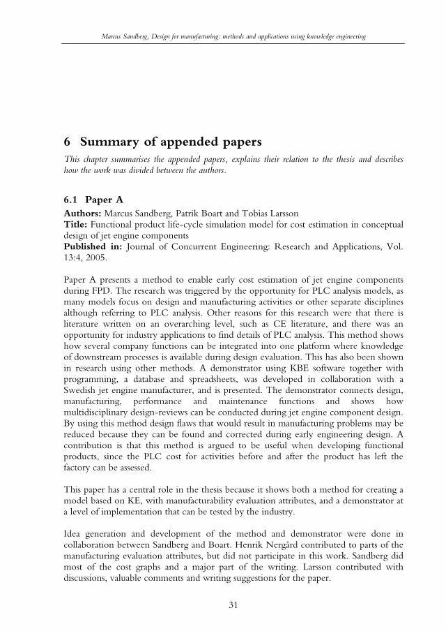
Marcus Sandberg, Design for manufacturing: methods and applications using knowledge engineering
31
6 Summary of appended papers This chapter summarises the appended papers, explains their relation to the thesis and describes how the work was divided between the authors.
6.1 Paper AAuthors: Marcus Sandberg, Patrik Boart and Tobias Larsson Title: Functional product life-cycle simulation model for cost estimation in conceptual design of jet engine components Published in: Journal of Concurrent Engineering: Research and Applications, Vol. 13:4, 2005.
Paper A presents a method to enable early cost estimation of jet engine components during FPD. The research was triggered by the opportunity for PLC analysis models, as many models focus on design and manufacturing activities or other separate disciplines although referring to PLC analysis. Other reasons for this research were that there is literature written on an overarching level, such as CE literature, and there was an opportunity for industry applications to find details of PLC analysis. This method shows how several company functions can be integrated into one platform where knowledge of downstream processes is available during design evaluation. This has also been shown in research using other methods. A demonstrator using KBE software together with programming, a database and spreadsheets, was developed in collaboration with a Swedish jet engine manufacturer, and is presented. The demonstrator connects design, manufacturing, performance and maintenance functions and shows how multidisciplinary design-reviews can be conducted during jet engine component design. By using this method design flaws that would result in manufacturing problems may be reduced because they can be found and corrected during early engineering design. A contribution is that this method is argued to be useful when developing functional products, since the PLC cost for activities before and after the product has left the factory can be assessed.
This paper has a central role in the thesis because it shows both a method for creating a model based on KE, with manufacturability evaluation attributes, and a demonstrator at a level of implementation that can be tested by the industry.
Idea generation and development of the method and demonstrator were done in collaboration between Sandberg and Boart. Henrik Nergård contributed to parts of the manufacturing evaluation attributes, but did not participate in this work. Sandberg did most of the cost graphs and a major part of the writing. Larsson contributed with discussions, valuable comments and writing suggestions for the paper.

Marcus Sandberg, Design for manufacturing: methods and applications using knowledge engineering
32
6.2 Paper B Authors: Marcus Sandberg, Peter Åström, Tobias Larsson and Mats Näsström Title: A design tool integrating CAD and virtual manufacturing for distortion assessmentPublished in: Proceedings of the International Conference on Engineering Design, August 15-18 2005, Melbourne, Australia.
Paper B deals with how engineering designs can automatically be configured and simulated for cutting. Commercial CAD-software usually facilitates simulations of dynamics and stiffness using FEA, and manufacturing process simulations of testing if available tools can manufacture the wanted geometry using CAM. However, simulations of stresses and deformations due to manufacturing process operations are not commonly included in commercial CAD-software. Therefore, analysis experts commonly perform these simulation activities, but there is usually a collaboration gap between engineering designers and analysis experts. A method for engineering designers to automatically perform routine cutting simulation is proposed. A demonstrator was developed using KBE, programming and nonlinear FEA software to show the possibilities that arise when the engineering designer can make design changes and directly assess distortion due to cutting. It is argued that by using the method, designs can be enhanced for manufacturability and the gap between engineering designers and computational experts can be reduced due to the integration of CAD and simulations. Research integrating KBE and FEA has been presented before for structural analysis, why this work contributes with integrating KBE and FEA for manufacturing simulations.
The relation of this paper to the thesis is that it provides information of manufacturing operations other than what production rules can accomplish, since FEA is used to predict distortion effects caused be residual stresses. KE is still in focus, as automation of the FEA is conducted through KBE, programming and scripts.
Åström and Sandberg discussed the idea and developed the method together. Sandberg did the KBE programming, Åström did the FEA programming and the scripts for connecting KBE and FEA were done by Sandberg with help from Åström. Åström and Sandberg wrote the paper and Larsson discussed the method with them and gave useful suggestions for the write up. Näsström gave editorial guidance for the writing.
6.3 Paper C Authors: Marcus Sandberg and Tobias Larsson Title: Automating redesign of sheet-metal parts in automotive industry using KBE and CBRPublished in: Proceedings of the ASME International Design Engineering Technical Conferences & Computers and Information in Engineering Conference, 10-13 September 2006, Philadelphia, USA.
Automating redesign is one way of enhancing products for manufacturability. This paper presents a method to combine KBE and CBR and extend the evaluation possibilities and facilitate automatic redesign due to poor manufacturability. Because

Marcus Sandberg, Design for manufacturing: methods and applications using knowledge engineering
33
CBR can enable an overarching search for manufacturing plans and KBE can enable “what-if”-analysis of details, an opportunity to combine these two methods was identified. The idea is to use commercial KBE software as a base for rule implementation for both KBE and CBR. Feature recognition of geometries can then be facilitated, since a parametric model that also enables topological changes is created and used as input for the CBR part. Evaluation can then be done in several steps. Performance evaluation, e.g. stiffness, can be performed using KBE, followed by the retrieval of the CBR part and if possible, the adaptation of a manufacturing plan. If the adaptation fails, an algorithm that suggests redesign proposals is triggered and the engineering designer can chose to follow or not follow the redesign proposals. If a manufacturing plan is adapted, using KBE again to change details of the design to enhance manufacturability is possible. This method was also exemplified as a demonstrator in collaboration with a Swedish car manufacturer, where portions of the KBE part were implemented. The method for combining KBE and CBR shows how manufacturability evaluation can be supported through several analysis steps using both KBE “what-if”-analysis and CBR plan based analysis. This method is believed to facilitate implementation of CBR into industry, because the KBE software is used as a base for implementation. Hence, feature recognition that could be time demanding and tricky to implement for CBR is also believed to become easier, since the geometry is already implemented in the KBE software. By using this method, manufacturing problems due to poor design are considered reduced. The bracket design demonstrator shows a scenario of how an automotive bracket can be designed and evaluated in several ways regarding sheet metal stamping operations. This can inspire the automotive industry to use KE in new ways to enhance manufacturability evaluation. This is a conceptual demonstrator that has not been fully implemented and tested. The method is believed to help the engineering designer evaluate manufacturability in more ways than by simply using KBE. Combinations of rule-based and CBR has been done before, though not common within mechanical engineering design, and therefore this work contributes with combining the rule-based KBE and CBR.
This paper’s relation to the thesis is by its focus on KE and manufacturability evaluation. The view of this paper is more computer science oriented than the other papers.
Sandberg conceived the idea of combining KBE and CBR and wrote the paper with comments and writing suggestions from Larsson.
6.4 Paper D Authors: Marcus Sandberg and Michael M. Marefat Title: Combining knowledge-based engineering and case-based reasoning for design and manufacturing iteration Published in: Proceedings of the 4th International Conference on Manufacturing Research, 5-7 September 2006, Liverpool, UK.
This paper presents another angle on the method of combining KBE and CBR, as presented in Paper C with a redesign focus, focusing on design and manufacturing iteration. Early iteration cycles between engineering design and manufacturing are

Marcus Sandberg, Design for manufacturing: methods and applications using knowledge engineering
34
crucial to avoid costly design flaws. A motive for this paper is that iteration seldom is in focus for automated design and manufacturing. It is shown how the combination of KBE and CBR can enable both automatic and manual iteration in several steps. It is argued that the user may trust the tool application more, since the automation is done in several steps with intermediate user interaction instead of automating everything in one step. Because four different iterations are possible there are several opportunities of finding ways to enhance the design.
The relation of this paper to the thesis is automated DFM in general and the targeting of iterative phases of engineering design in particularly.
It was Sandberg’s idea to focus on iteration and Marefat gave advice of the CBR part. Sandberg wrote the paper.
6.5 Paper E Author: Marcus Sandberg Title: Manufacturability evaluation in early design: On the dependency of business commitmentPublished in: Proceedings of the 5th International Conference on Manufacturing Research, 11-13 September 2007, Leicester, UK.
This paper presents a study that tests the hypothesis “manufacturability evaluation depends on the business commitment”, due to emerging new business commitments such as product service systems, total offers and functional products, and the lack of earlier studies on the subject. Empirical data is based on a number of interviews and one workshop conducted with the staff from a Swedish jet engine manufacturer. The result shows that manufacturability evaluation is likely to be changed if a total offer commitment is made. It is argued that the more design parameters the company can change or control, often the case when making a higher business commitment, the more manufacturability parameters are affected. Certain results favour the hypothesis less, e.g. the same product development process is used for both make-to-print and transaction of physical artefacts commitments, though these commitments are different.
This paper is included in the thesis because FPD is once again highlighted, as in Paper A, this time with more focus on manufacturability.
Sandberg came up with the idea to investigate the hypothesis and the interviews were planned and performed by the same. The workshop was done in collaboration with other Ph.D. students of the Division of Functional Product Development and had a wider topic than the focus of the paper.
6.6 Paper F Authors: Marcus Sandberg, Helena Johnsson and Tobias Larsson Title: Knowledge-based engineering in construction: The prefabricated timber housing casePlace published: Submitted to Journal of Information Technology in Construction

Marcus Sandberg, Design for manufacturing: methods and applications using knowledge engineering
35
Paper F deals with how IT (information technology) support can be used to make companies within the construction industry, or specifically timber element volume prefabricators, more effective and efficient. A method to use modularisation and KBE to enhance information management and CAD work during design is proposed. A study at a Swedish TVE prefabricator is presented and issues found regarding information management are presented. A documented information strategy seems to be lacking and CAD work lack use of assembly instances and parameterisation, and are therefore time demanding. Design flaws found during production are not always updated in the solid models, as the workers perceive the houses as one-of-a-kind houses. Information is not always accessible as computer files, rather as document folders containing print-outs. The proposed method is argued to be suitable for enhancing CAD work along with creating an information strategy. A scenario based on the study is presented, where the proposed method is discussed about being used for creating a sell and design support for the choice of stairs. When a stair is chosen, the interfacing geometry would automatically change and a production cost estimate can be automatically calculated. The method for supporting early engineering design of timber volume element prefabrications is believed to strengthen the information strategy of timber volume element companies, since KE and modularisation could create a new CAD environment. Work would then be based on parametric models to reduce timely, routine work. KBE also permits finding design flaws that would have resulted in production problems, because rules for manufacturability evaluation can be implemented in KBE software. This method can be used to discuss and inspire the creation of a new CAD environment that would enable the automation of routine work. The method could also be used as a base when creating an information strategy. The research contributes with applying KBE in a new area, namely timber prefabrication.
This paper is different from the others regarding industry partner, but is similar as engineering design, KE and manufacturability are still in focus.
The idea of using KBE in design for timber volume element prefabrication was formulated by Lars Stehn, Johnsson and Larsson, and developed by Sandberg. Johnsson provided the process map that was evaluated during the case study. Sandberg wrote the paper with writing feedback from Johnsson and Larsson.
Marcus Sandberg, Design for manufacturing: methods and applications using knowledge engineering
36
7 DiscussionThis chapter discusses the contribution of the presented research in relation to the research question, aim and scope, and earlier research.
As presented before the research question is:
How to use knowledge engineering to enhance manufacturability evaluation during early design when having a life-cycle view?
The first part of the question is ”How to use knowledge engineering…” and in this thesis, KE has been used in three ways:
rule-based rule-, programming- and FEA-based rule- and plan-based
Each way is described further in the sections below, and beneficial and less beneficial properties, as outlined in the aim, for how the ways can ”enhance manufacturability evaluation during early design when having a life-cycle view”, as in the second part of the research question, are discussed. Automation and implementation are also discussed.
Automation of design activities is focus upon in the proposed methods. However, there is a risk that a black box is achieved if key knowledge is not explained to the user, e.g. the design rationale. However, the pocket calculator could be seen as a useful black box that automates calculations, since the user does not usually need to understand the knowledge that governs the automation, to successfully use the pocket calculator. With key knowledge for computer-based design support, knowledge that explains why something can be enhanced in terms of manufacturability is in focus, e.g. an error message is generated indicating that the factory cannot manufacture the current design and why this is not possible. Explaining key knowledge will increase the understanding of the manufacturing process, as the design support functions as an educator. A balance between manual and automated work is needed for the engineering designer to be the one who makes the decisions, while the design support creates the decision base.
With implementation, the act of coding tools based on the proposed methods is in focus. The presented methods are based on using KBE, a rule-based way of applying KE. The methods presented are based on KBE software, which is part of widespread CAD-software, and therefore used by the manufacturing industry. Hence, the presented methods are believed to have industry potential as compared to methods

Marcus Sandberg, Design for manufacturing: methods and applications using knowledge engineering
37
using research lab specific software. Sharma and Gao (2002) argue that it is useful to separate application and analysis knowledge for design support applications. However, synthesis knowledge, which is part of application knowledge, may also change if new products are developed.
7.1 Rule-basedThis section discusses the rule-based way of modelling knowledge and the two proposed methods using this way.
7.1.1 Knowledge modelling In the rule-based way, knowledge is modelled using mainly production rules, and explicit knowledge is considered suitable. Therefore, the rule-based way includes using KBE to create a rule-base for automation and enabling of engineering knowledge. The rule-based way is more straightforward to implement than the other two ways, as scripts and CBR algorithms are excluded, but is limited to generating results processed from explicit knowledge in terms of production rules, parametric and constant relationships. It is, however, possible to make available manufacturing knowledge together with other PLC parts in the CAD-environment, which might be valuable for design evaluation. The benefit is believed to be highest for limited parts of the product because the rule-base will grow larger and need structured and systematic maintenance if the product data grows. The rule-based way is presented in the multidisciplinary method for manufacturability evaluation during FPD and the method for design and manufacturing evaluation in construction.
7.1.2 Multidisciplinary method for manufacturability evaluation of functional products
The multidisciplinary method shows how activities from the PLC, as represented by design, manufacturing, performance and maintenance, can be integrated in a design support application. This variety of disciplines included is seldom seen in a separate rule-based system. Since activities occurring after manufacturing are included together with manufacturability evaluation, the method is argued to be suitable for FPD. This is because FPD requires control of cost for product maintenance and manufacturing, as these activities affect the cost of providing availability. Because engineering designers can directly assess cost and manufacturability, there is a possibility to avoid costly and late iterations due to design flaws. This has also been noted in earlier results from, e.g. (Venkatachalam, 1994). A criterion for a useful automation model is that the real process does not change compared to the model. There is also a need to integrate these kinds of design support applications with PLM systems to avoid an isolated island where the only interface between the support tool and PLM system is humans (Catic and Malmqvist, 2007).
7.1.3 Design and manufacturing evaluation in construction The method for design and manufacturing evaluation in construction contains modular function deployment as an aid to formalise an engineering design automation application, since the product family can be structured and standardised to create a design process that follows an IT strategy. This can enhance the information flow within companies, which also is noted for KBE by Chapman and Pinfold (1999). This

Marcus Sandberg, Design for manufacturing: methods and applications using knowledge engineering
38
IT strategy can promote efficient design and manufacturing iteration, as the CAD environment can be enhanced by means of creating parametric models and incorporating manufacturing knowledge for reuse of earlier results. Further, the CAD environment is seen as an enabler for knowledge reuse (Johansson and Kliger, 2007). One contribution with this work is showing the possibility of using KBE for timber prefabrication. The standardisation effort may however be time demanding and challenging as it also may require a cultural change from doing unique one-of-a-kind products to reusing earlier results.
7.2 Rule-, programming- and FEA-based This section discusses the rule, programming- and FEA-based way of modelling knowledge and the proposed method using this way.
7.2.1 Knowledge modelling In the rule-, programming- and FEA-based way, knowledge is modelled using production rules, object oriented programming, procedural scripts and FEA software macros. Besides explicit knowledge, it is also possible to capture tacit knowledge in the FEA software macros, since the computational expert “records” every step during the simulation and may not necessarily be able to explain the rationale behind every step, i.e. why the step is done in a certain way. The rule-, programming-, and FEA-based way also includes, besides employing KBE, using programming to automate an information transfer between CAD and FEA software. The rule-, programming- and FEA-based way extends manufacturing information by making simulation results in terms of stresses and displacements available, but requires a more extensive programming effort compared to the rule-based way. The rule-, programming- and FEA-based way was used to assess distortion of cutting using an element deactivation method that is relatively easy to implement, is representative of routine work, and is therefore suitable for integration with the KBE software. The issue of making programming generic, i.e. to be applied on generic geometries and therefore reusable, is a challenge and require a systematic approach and probably more coding. It has been argued that KBE can be used for FE model creation by geometry simplification (Pinfold and Chapman, 2001), though the proposed method in this thesis includes the complete analysis, comprising pre-processing, solving and post processing.
7.2.2 Integration of design and manufacturing simulation The rule-, programming- and FEA-based way was used in the method to integrate design and manufacturing simulations. Because the engineering designer can evaluate stresses and displacements, there is a possibility to find geometry solutions that minimize problems with product tolerances that would otherwise be caused by manufacturing operations. Automation of design and manufacturing operations simulations in terms of stresses and displacements is uncommon. The engineering designer can achieve an understanding of manufacturing operations, as feedback of manufacturing operation configurations is given, and enable better conformance of product geometries in the future.

Marcus Sandberg, Design for manufacturing: methods and applications using knowledge engineering
39
7.3 Rule- and plan-based This section discusses the rule and plan-based way of modelling knowledge and the proposed method using this way.
7.3.1 Knowledge modelling The rule- and plan-based way is a combination of KBE and CBR. By using CBR, there is the possibility to capture knowledge that is more complicated to transform into rules than routine work. This capture occurs, since knowledge being more tacit can be captured within the plans (cases) and new tacit knowledge can be added automatically to the knowledge base (Hopgood, 2001). This way is, therefore, more dynamic compared to the static knowledge model of recorded macros of the rule-, programming- and FEA-based way. There is other research that employ CBR and rules, e.g. (Marling et al., 1999), but few within DFM why this research is seen as a contribution.
7.3.2 Automated redesign and manufacturability iteration The method for automated redesign and manufacturability iteration utilises this way since CBR uses earlier manufacturing plans to automatically assess manufacturability. The rule- and plan-based way is also based on KBE, and the CBR algorithms presented are basically overarching suggestions of how to proceed during implementation. The rule- and plan-based method enables manufacturability evaluation in several iterations, since both KBE rules and CBR are used. Automation is performed in several steps with intermediate manual steps, and is believed to be easier for the user to grasp instead of having all steps automated in one. This creates several opportunities to find design flaws. Details of the CBR-algorithms have to be resolved in future work. The combination of CBR and KBE is new and seen as a contribution. It is argued that feature recognition can be facilitated using KBE instead of creating an algorithm to recognise general geometries, which is, if not impossible, at least time demanding and challenging. The recognisable features are, however, limited to the geometries implemented in the KBE software. Rentema (2004) also presents an approach based on initially retrieving earlier cases and using rules to define details of the engineering design, but manufacturing evaluation is not in scope of the research. Ramana and Rao (2005) also present a rule- and plan-based method for manufacturability evaluation and refer to plan-based as the act of generating a complete process plan, instead of basing the manufacturability reasoning on recent plans, as in the rule- and plan-based method presented in this thesis.
7.4 Manufacturability evaluation and business commitment
Design and manufacturing need to have a PLC perspective, or at least a wider picture by involving purchasing and others not commonly involved during product development for the transaction of physical artefacts when making PLC commitments. The research has presented pros and cons for the hypothesis “manufacturability evaluation depends on the business commitment”. It may seem obvious that change of design influence in turn affect manufacturability evaluation activities, but it is more a matter of finding the manufacturability parameters that are and are not affected by the business commitment. These parameters can guide the change of engineering design activities to better conform to higher commitments, such as total offers. Further more, the
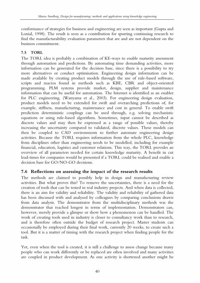
Marcus Sandberg, Design for manufacturing: methods and applications using knowledge engineering
40
conformance of strategies for business and engineering are seen as important (Gupta and Lonial, 1998). The result is seen as a contribution for spurring continuing research to find the manufacturability evaluation parameters that are and are not dependent on the business commitment.
7.5 TORL
The TORL idea is probably a combination of KE-ways to enable maturity assessment through automation and predictions. By automating time demanding activities, more information can be generated for the decision base, since there is a possibility to try more alternatives or conduct optimisation. Engineering design information can be made available by creating product models through the use of rule-based software, scripts and macros found in methods such as KBE, CBR and object-oriented programming. PLM systems provide market, design, supplier and maintenance information that can be useful for automation. The Internet is identified as an enabler for PLC engineering, (Wanyama et al., 2003). For engineering design evaluation, product models need to be extended for swift and overarching predictions of, for example, stiffness, manufacturing, maintenance and cost in general. To enable swift prediction deterministic couplings can be used through, e.g. solving mechanistic equations or using rule-based algorithms. Sometimes, input cannot be described as discrete values and may then be expressed as a range of possible values, thereby increasing the uncertainty compared to validated, discrete values. These models can then be coupled to CAD environments to further automate engineering design activities. Because the TORL requires information from the whole PLC, knowledge from disciplines other than engineering needs to be modelled, including for example financial, education, logistics and customer relations. This way, the TORL provides an overview of all parameters needed for certain knowledge maturity. A benefit in cut lead-times for companies would be presented if a TORL could be realised and enable a decision base for GO/NO-GO decisions.
7.6 Reflections on assessing the impact of the research results The methods are claimed to possibly help in design and manufacturing review activities. But what proves this? To remove the uncertainties, there is a need for the creation of tools that can be tested in real industry projects. And when data is collected, there is an aim for validity and reliability. The validity and reliability of gathered data has been discussed with and analysed by colleagues by comparing conclusions drawn from data analysis. The demonstrator from the multidisciplinary methods was the demonstrator that reached longest in terms of implementation. Demonstrators can, however, merely provide a glimpse or show how a phenomenon can be handled. The work of creating tools used in industry is closer to consultancy work than to research, and is therefore often outside the budget of research project. Master students can occasionally be employed during their final work, currently 20 weeks, to create such a tool. But it is a matter of timing with the research project when finding people for the task.
Yet, even when the tool is created, it is still a challenge to assess change because many people who can work differently or be replaced are often involved and many activities are coupled in product development. As one activity is shortened another might be

Marcus Sandberg, Design for manufacturing: methods and applications using knowledge engineering
41
made longer. The process that is supported and automated in the tool may also change because the tool is out of date. Therefore, it is important to have an overarching understanding of the company process, preferably with time approximations, which was an issue particularly in focus during the work in the construction industry project.
Time is only one parameter that can be measured. For the method combining design and manufacturing simulations, component quality was believed to increase as distortion effects could be avoided. Measuring quality is perhaps even tougher, since it may require measuring product quality for a long time to conclude any difference. It is also possible to have a more qualitative approach when assessing improvement by conducting interviews of people of the company that are affected by the tool.

Marcus Sandberg, Design for manufacturing: methods and applications using knowledge engineering
42
8 ConclusionThis thesis presents research aimed at developing new methods for manufacturability evaluation during early design using KE and to evaluate beneficial and less beneficial properties of these methods. The research was conducted in collaboration with the Swedish manufacturing industry involving one jet engine manufacturer and one automotive manufacturer, and the construction industry with one timber volume element prefabricator. This section summarises the contribution from this research and outlines some ideas for future work.
8.1 Scientific and industrial contribution The overall scientific contribution is a provision of new methods to support design for manufacturing by automating early engineering design activities and making corporate knowledge available. The methods can inspire researchers embarking in the field of manufacturability evaluation using KE. The overall industrial contribution is providing insight by the presentation of the demonstrators. As applied research integrates academia and industry, research contributions will overlap and sometimes merge, no division of scientific and industrial contribution is done. More specifically, the scientific and industrial contributions from this thesis work can be summarised as:
A comparison of three ways involving knowledge modelling for design for manufacturing
o In the rule-based way, knowledge is modelled using production rules, and parametric and constant relationships. The rule-based way is more straightforward to implement than the other two ways but is limited to generating results processed from explicit knowledge. This way has been used in two proposed methods: multidisciplinary manufacturability evaluation during functional product development and design and manufacturing evaluation in construction.
o In the rule-, programming- and FEA-based way, knowledge is modelled using production rules, object oriented programming, procedural scripts and FEA software macros. Besides explicit knowledge, it is also possible to capture tacit knowledge in the FEA software macros. Making the programming reusable is a challenge as concluded in recent results. This way was used in the method for integration of design and manufacturing simulation.
o In the rule- and plan-based way, there are also possibilities to model both explicit and tacit knowledge, as concluded in recent results. Since new knowledge is added, as new plans are stored, this way is more dynamic

Marcus Sandberg, Design for manufacturing: methods and applications using knowledge engineering
43
compared to the static knowledge model of recorded macros. The method for automated redesign and manufacturability iteration uses this way.
A method for multidisciplinary manufacturability evaluation of functional product development that enables design for manufacturing in the context of several other PLC components, with an extensiveness of disciplines seldom seen in a rule-based system for manufacturability evaluation. As concluded in other research, rule-based systems may enable engineering designers to directly assess manufacturability and avoid costly and late iterations due to design flaws.A method for design and manufacturing evaluation in construction. This method can promote efficient design and manufacturing iteration because the information flow can be enhanced, also noted in earlier research, the CAD environment can be enhanced by means of parametric models and manufacturing knowledge. This method contributes by applying KBE in a new field, namely timber prefabrication.A method for integration of design and manufacturing simulation that automates design and simulation of stresses and displacements, in the product, to minimise problems caused by manufacturing operations. Other research show integrations of KBE and structural FEA and often only parts of the simulation process why this method contribute with integration of KBE and manufacturing simulation and simulating the whole process of FEA. A method for automated redesign and manufacturability iteration that combines KBE and CBR, and promotes several opportunities to find design flaws. It is argued that manufacturability can be enhanced in several ways since both rules and plans are used. The act of combining KBE and CBR is new. Identification of dependencies between manufacturability evaluation and business commitment. This is a research topic that has not been found before. It is argued that manufacturability evaluation needs to be more integrated with remaining company disciplines, when making contractual agreements involving a higher commitment, such as total offers. Prescribing ideas for a TORL design support. Technology readiness levels are mostly seen in other research while the proposed ideas promote readiness assessment of manufacturing and other PLC properties. A benefit in cut lead-times for companies would be presented if a TORL could be realised and enable a decision base for GO/NO GO decisions. DFM using KE can be domain independent. This can be said since the methods are argued to be useful in the application areas of aerospace, automotive and timber prefabrication.
8.2 Suggestions for future research This section describes some suggestions for future research regarding maintenance and organisational issues of knowledge engineering.
8.2.1 MaintenanceKeeping the design support up-to-date is crucial for its usefulness. If it is possible for users and those affected by the tool to continuously update, the tool might have the latest information and be continuously evaluated, as the user is also the evaluator.

Marcus Sandberg, Design for manufacturing: methods and applications using knowledge engineering
44
Weerasinghe and Salustri (2007) report on the usefulness of Wikis as an engineering collaborative tool to store engineering design knowledge. Although the idea of the Internet dictionary Wikipedia19, i.e. a Wiki, where every user can change information and discuss the contents with other users, may lead to a constantly updated information database, more research is needed to investigate how engineering design can benefit from the Wikipedia way.
8.2.2 OrganisationalIntroducing new design supports can affect the organisation. People might be sceptical to new tools and prefer the older tools. There might be cultural changes, where new roles such as knowledge engineers or a project information officer might be needed (Froese, 2004). As the methods integrate company knowledge, e.g. design, manufacturing evaluation, there is an opportunity to integrate the company functions into a group that together can update the tool. There is, however, a need for more research regarding organisational issues.
19 www.wikipedia.org, last accessed 2007-11-02

Marcus Sandberg, Design for manufacturing: methods and applications using knowledge engineering
45
References Akman, V., ten Hagen, P. J. W., and Tomiyama, T., (1990), A fundamental and
theoretical framework for an intelligent CAD system, Computer-Aided Design, Vol. 22, pp. 352-367.
Alonso-Rasgado, T., Thompson, G., and Elfström, B. O., (2004), The design of functional (total care) products, Journal of Engineering Design, Vol. 15, pp. 515-540.
Andreassen, M. M., and Hein, L. (1987), Integrated Product Development, IFS/Springer-Verlag, Berlin.
Asiedu, Y., and Gu, P., (1998), Product life cycle cost analysis: state of the art review,Intenational Journal of Production Research, Vol. 36, pp. 883-908.
Barton, J., Love, D. M., and Taylor, G. D., (2001), Design determines 70% of cost? A review of implications for design evaluation, Journal of Engineering Design, Vol. 12, pp. 47-58.
Bathe, K.-J. (1996), Finite element procedures, Prentice Hall, Upper Saddle River, New Jersey.
Boart, P., (2007), The enabling of product information in the conceptual phase, Doctoral thesis, Luleå University of Technology.
Boothroyd, G., Dewhurst, P., and Knight, W. A. (2001), Product design for manufacture and assembly, CRC Press, New York.
Bralla, J. G. (1999), Design for manufacturability handbook, McGraw-Hill, New York. Catic, A., and Malmqvist, J., (2007), Towards integration of KBE and PLM, International
conference on engineering design, Paris, France. Cederfeldt, M., (2007), Planning design automation: A structured method and supporting tools,
Doctoral thesis, Chalmers, Göteborg. Chapman, C. B., and Pinfold, M., (1999), Design engineering - a need to rethink the
solution using knowledge based engineering, Knowledge-Based Systems, Vol. 12, pp. 257-267.
Chi, R. T. H., and Kiang, M. Y., (1991), An integrated approach of rule-based and case-based reasoning for decision support, ACM Computer Science Conference
Cross, N. (2000), Engineering design methods: strategies for product design, Wiley, Chichester.
Elgh, F., (2007), Computer-Supported Design for Producibility: Principles and Models for System Realisation and Utilisation, Doctoral thesis, Chalmers, Gothenburg.
Ericson, Å., (2006), Functional Product Development - An Explorative View, Licentiate thesis, Luleå University of Technology, Luleå.
Ericson, Å., Bergström, M., Johansson, C., and Larsson, T., (2007), On the way to knowledge awareness in early design, 17th International Design Seminar, Berlin, Germany.

Marcus Sandberg, Design for manufacturing: methods and applications using knowledge engineering
46
Erixon, G., Erlandson, A., von Yxkull, A., and Mo Östergren, B. (1994), Modulindela produkten (in Swedish), Kristianstads Boktryckeri AB, Kristianstad.
Finger, S., Tomiyama, T., and Mäntylä, M. (1998), Knowledge Intensive CAD, Kluwer. Froese, T. M., (2004). Help wanted: project information officer, ECPPM 2004 - eWork and
eBusiness in Architecture, Engineering and Construction, A. Dikbas and Scherer, R., eds., Istanbul, Turkey, 19-24.
Gupta, Y. P., and Lonial, S. C., (1998), Exploring linkages between manufacturing strategy, business strategy, and organizational strategy, Production and operations management, Vol. 7, pp. 243-264.
Hicks, D. T. (1999), Activity-based costing: making it work for small and mid-sized companies,Wiley, New York.
Hopgood, A. A. (2001), Intelligent systems for engineers and scientists, CRC Press, Boca Raton.
IMTI, (2000), Integrated Manufacturing Technology Roadmapping Project, IMTR M&S Workshop Group and IMTR Roadmapping Project Team.
Johansson, P., and Kliger, R., (2007), Knowledge reuse in the design of steel connections using 2D-CAD drawings, Journal of Information Technology in Construction, Vol. 12, pp. 1-18.
Kalhori, V., (2000), Modelling and Simulation of Mechanical Cutting, Doctoral Thesis, Luleå University of Technology.
Kelley, T., and Littman, J. (2004), The Art of Innovation: Lessons in Creativity from IDEO, America's Leading Design Firm, Profile Books.
Kensing, F., and Madsen, K. H., (1991). Generating Visions: Future Workshops and Metaphorical Design, Design at work: Cooperative design of computer systems, Greenbaum, J. and Kyng, M., eds., Lawrence Earlbaum, Hillsdale.
Kuo, T.-C., Huang, S. H., and Zhang, H.-C., (2001), Design for Manufacture and for "X": Concepts, Applications and Perspectives, Computers and Industrial Engineering, Vol. 41, pp. 241-260.
Lantz, A. (1993), Intervjumetodik (in Swedish), Studentlitteratur, Lund. Lawrence, A., (1994), VM User Workshop Final Report, V2, Virtual Manufacturing User
Workshop, Dayton. Löfstrand, M., (2007), A modelling and simulation approach for linking design activities to
business decisions, Doctoral thesis, Luleå University of Technology, Luleå. Marefat, M., and Britanik, J., (1997), Case-based process planning using an object-oriented
model representation, Robotics and Computer-Integrated Manufacturing, Vol. 13, pp. 229-251.
Marling, C. R., Petot, G. J., and Sterling, L. S., (1999), Integrating case-based and rule-based reasoning to meet multiple design constraints, Computational Intelligence, Vol. 15, pp. 308-332.
Mont, O., (2002), Clarifying the Concept of Product-Service System, Journal of Cleaner Production, Vol. 10, pp. 237-245.
Nanua, S., Ding, S., Jagirdar, R., and Basil, E. A., (1997), A knowledge engineering framework for rapid design, Computers & Industrial Engineering, Vol. 33, pp. 345-348.
Nergård, H., (2006), Knowledge enabled engineering systems in industrial product development: towards cross company collaboration, Licentiate Thesis, Luleå University of Technology, Luleå.

Marcus Sandberg, Design for manufacturing: methods and applications using knowledge engineering
47
Pahl, G., and Beitz, K. (1996), Engineering design: a systematic approach, Springer, Berlin. Pal, S. K., and Shiu, S. C. K. (2004), Foundations of soft case-based reasoning, John Wiley
& Sons, Hoboken. Pawar, K. S., Haque, B., and Weber, F., (2002), Computer Based Initiatives for
Implementing and Sustaining Concurrent Engineering, Concurrent Engineering: Research and Applications, Vol. 10, pp. 75-93.
Pinfold, M., and Chapman, C., (2001), The Application of KBE Techniques to the FE Model Creation of an Automotive Body Structure, Computers in Industry, Vol. 44, pp. 1-10.
Prasad, B. (1997), Concurrent engineering fundamentals: Integrated product development, Vol. II, Prentice and Hall, Saddle River, New Jersey.
Prasad, B., (2000), Survey of life-cycle measures and metrics for concurrent product and process design, Artificial Intelligence for Engineering Design, Analysis and Manufacturing, Vol. 14, pp. 163-176.
Priest, J. W., and Sánchez, J. M. (2001), Product development and design for manufacturing: a collaborative approach to producibility and reliability, M. Dekker, New York.
Ramana, K. V., and Rao, P. V. M., (2005), Automated manufacturability evaluation system for sheet metal components in mass production, International Journal of Production Research, Vol. 43, pp. 3889-3913.
Rentema, D., (2004), AIDA: artificial intelligence supported conceptual design of aircraft, PhD Thesis, Delft University of Technology, The Netherlands.
Rittel, H., and Webber, M., (1973), Dilemmas in a General Theory of Planning, Policy Sciences, Vol., pp. 155-169.
Rosenfeld, L. W., (1995). Solid Modeling and Knowledge-Based Engineering, Handbook of Solid Modeling, LaCourse, D. E., ed., McGraw-Hill, Inc., New York.
Sandberg, S., Kalhori, V., and Larsson, T., (2004), FEM Simulation supported KEE in high strength steel car body design, Proceedings of IMECE04 2004 ASME International Mechanical Engineering Congress, Anaheim, California USA.
Savage, J., (2000), Participative observation: Standing in the shoes of others? Qualitative Health Research, Vol. 10, pp. 324-339.
Sharma, R., and Gao, J. X., (2002), A Progressive design and manufacturing evaluation system incorporating STEP AP224, Computers in Industry, Vol. 47, pp. 155-167.
Shehab, E. M., and Abdalla, H. S., (2001), Manufacturing cost modelling for concurrent product development, Robotics and Computer-Integrated Manufacturing, Vol. 17, pp. 341-353.
Silverman, D. (2005), Doing qualitative research, SAGE Publications, London. Stark, J. (2005), Product Lifecycle Management: 21st Century Paradigm for Product
Realisation, Springer, London, UK. Stokes, M. (2001), "Managing Engineering Knowledge - MOKA: Methodology for Knowledge
Based Engineering", ASME Press. Studer, R., Benjamins, V. R., and Fensel, D., (1998), Knowledge Engineering: Principles
and methods, Data & Knowledge Engineering, Vol. 25, pp. 161-197. Ulrich, K. T., and Eppinger, S. D. (2004), Product design and development, McGraw-Hill,
Boston.Wang, L., Shen, W., Xie, H., Neelamkavil, J., and Pardasani, A., (2002), Collaborative
Conceptual Design - State of the art and future trends, Computer-Aided Design, Vol. 34, pp. 981-996.

Marcus Sandberg, Design for manufacturing: methods and applications using knowledge engineering
48
Wanyama, W., Ertas, A., Zhang, H.-C., and Ekwaro-Osire, S., (2003), Life-cycleengineering: issues, tools and research, International Journal of Computer Integrated Manufacturing, Vol. 16, pp. 307-316.
Weerasinghe, J. S., and Salustri, F. A., (2007), Use of wikis as an engineering collaborative tool, Interational Conference on Engineering Design, Paris, France.
Venkatachalam, A. R., (1994), Automating manufacturability evaluation in CAD systems through expert systems approaches, Expert Systems with Applications, Vol. 7, pp. 495-506.
Wright, I. C. (1998), Design methods in engineering and product design, McGraw-Hill, London.

PAPER A
Sandberg M., Boart P. and Larsson T., Functional product life-cycle simulation model for cost estimation in conceptual design of jet engine components, Journal of Concurrent Engineering: Research and Applications Vol. 13:4, 2005.
Copyright: Sage Publications Ltd


PAPER A
1
FUNCTIONAL PRODUCT LIFE-CYCLE SIMULATION MODEL FOR COST ESTIMATION IN CONCEPTUAL
DESIGN OF JET ENGINE COMPONENTS
Marcus Sandberg,1 Patrik Boart1,2 and Tobias Larsson1
1Polhem Laboratory, Luleå University of Technology, SE-971 87 Luleå, Sweden 2Advanced Design Engineering, Volvo Aero Corporation, SE-461 81 Trollhättan,
Sweden
As functional (total care) products emerge in the jet engine industry, the need for product life-cycle models capable of definition and evaluation of life cycle properties increases, since functional products include both hardware and service. Recent life-cycle models are intended for hardware products and mostly handle design and manufacturing knowledge. The aim of this paper is to present a design approach that extends the evaluation capabilities beyond classical hardware design and manufacturing evaluation. The focus has been to introduce evaluation of manufacturing and post-manufacturing activities in evaluation of conceptual designs. For this purpose, a model has been proposed to handle the information flow between teams when developing structural jet engine components. A case study, in which the proposed model was used in cooperation with a jet engine component manufacturer, is presented. Aspects concerning design, manufacturing, performance and maintenance of jet engine flanges were included in the example by means of a KBE-system coupled to databases and spreadsheets. The model is more suitable than recent work for the development of hardware of functional products, since knowledge from more product development disciplines is included. As the engineer changes the design and directly assesses the life-cycle cost and how the changes impact the interface to other jet engine components, more knowledge on the impact of design decisions is available at hand for the engineering designer than without the model.
Keywords: Knowledge-based engineering, product life-cycle, cost, design support systems, conceptual design
1 Introduction Assessing the life-cycle cost of a product during product development is crucial for product success. Hardware product development has worked towards a life-cycle view for several years, (Prasad, 1996; Prasad, 1997). As functional products (FP) emerge in the jet engine industry (Alonso-Rasgado et al., 2004), the product life-cycle view has to be refined. A FP is a total care product, where the company offers the functionality of the product, compromising hardware and support services, e.g. maintenance, logistics, financing and training over the life-time of the offer. Today, most jet engine manufacturers are remunerated late in the life-cycles of services on already sold hardware. The manufacturer owns the product while the customer is charged for the operative use of the product. This increases the risk for the manufacturer, since

PAPER A
2
customers are typically guaranteed product availability, and creates new requirements on the manufacturer’s PD process because it has to be adapted to FP design, hardware and service development rather than hardware design alone. It is no longer just a design-manufacture-sell issue, but rather a total care issue.
The aero engine business companies join together to share risk. With a common product to develop, where the different components of the jet engine are divided between the partners, it is necessary to share information and see the effects of each decision. With a FP scenario this is especially important in the early phases. Few applications exist that can support the conceptual design phase in such an enterprise, (Wang et al., 2002). This is partly because that knowledge about the design requirements and constraints is usually imprecise and incomplete. As the life-cycle of the FP is largely decided upon in the early phases, better tools that can improve the knowledge about how different decisions will affect the product life-cycle are needed.
Figure 1 shows an excerpt of an overview of the system levels in an aircraft engine. Each module consists of a number of components. A change in one component can affect the interface properties in relation to other components. Contracts are used to define what requirements each interface must fulfill. If a change that will affect a requirement in one interface is needed, costly negotiation may ensue. Usually, it is only in the early phases of product development that larger changes are admissible or affordable.
Aircraft Engine
(system Level)
Aircraft
CoreModule
(Subsystem Level)
Accessory Drive
Modules(Subsystem
Level)
Fan and BoosterModule
(Subsystem Level)
Fan Frame(Component
Level)
Low-PressureTurbine Module
(SubsystemLevel)
Fan and Booster
(Component Level)
BearingSupport
(Component Level)
Low-PressureTurbine Frame
(Component Level)
Low-PressureTurbine Shaft
(Component Level)
Low-PressureTurbine
(Component Level)
Low-PressureTurbine Frame
(Component Level)
Low-PressureTurbine Shaft
(Component Level)
Low-PressureTurbine
(Component Level)
Figure 1. Excerpt from an aircraft system level overview.
Evaluating how changes affect the FP life-cycle cost is time consuming. The first obstacle is to manage the contractual agreement efficiently. To make these changes

PAPER A
3
efficiently all partners will need to know how the change will affect the life-cycle cost and how they, themselves, will be affected.
Generally, a concurrent engineering approach is a common means of making a product development process efficient and effective by paralleling and integrating PD processes, (Prasad, 1996; Prasad, 1997). However, this implies other challenges in managing the product development process as parallel and overlapping activities possibly generate design conflicts. Defining metrics and measures to handle the design conflicts is therefore important, (Prasad, 2000). Specifically, it is commonly claimed that one important part of the PD process is the conceptual phase, (Wang et al., 2002), where the boundaries of the product life-cycle are defined and a large part of the product cost to be covered later in the production system is thereby committed, (Barton et al., 2001). This cost is, however, not often seen until it has occurred, which is why designers may commit more cost than needed, (Kuo et al., 2001). One way of making the cost visible in the conceptual phase is through the life-cycle cost (LCC) modeling.
A state-of-the-art study regarding product LCC modeling in the early phases of PD has been presented by Gu & Asiedu (1998), who concluded that most work often concentrates on design and manufacturing activities as recent work often deals with hardware development. More recent work has also focused on hardware products and therefore lacks a wider life-cycle perspective, (Blair and Hartong, 2000; Shehab and Abdalla, 2001). Hence, modeling post-manufacturing activities of the life-cycle is necessary.
The aim of this paper is to present a design approach that extends the evaluation capabilities beyond classical hardware design and manufacturing evaluation. The focus has been to introduce evaluation of manufacturing and post-manufacturing activities in evaluation of conceptual designs.
The major contribution from this work is the design support model, which can be used to assess life-cycle cost and create a view of how decisions between a number of design, performance, manufacturing and maintenance activities affect each other in conceptual design. Designers can jointly assess LCC change due to design changes. It is believed that the design support model is more suitable for development of hardware parts of functional products (HFP) than recent work because of a wider life-cycle perspective.
The next section summarizes related work regarding the life-cycle cost modeling of mechanical engineering products. Section 3 introduces the proposed model, while section 4 presents a case study example. Section 5 discusses the usefulness of the design support model. The last section sums up the work and underlines the main conclusions.
2 Life-cycle cost simulation framework Simulating the total product life-cycle is a topic which was highlighted in the beginning of the 1990s through concurrent engineering (CE) presenting a systematic approach to achieving integrated product development. Based on the systematic approach, a vast number of life-cycle cost simulation applications have been presented, of which a selection is discussed.

PAPER A
4
2.1 Systematic approach Concurrent engineering (CE) sets the framework for how to integrate product and process organizations (Prasad, 1996) and achieve integrated product development (Prasad, 1997). The main theme in CE is the paralleling of engineering processes and activities that earlier on was performed sequentially. Another theme in CE is the modeling of life-cycle activities using geometry-based, constraint-based and knowledge-based languages and thereby making downstream knowledge (knowledge related to a product development process which is conducted later) available in early design, (Prasad, 1997), as it is commonly claimed that a majority of the product cost is allocated during the early design stages, (Barton et al., 2001; Wang et al., 2002). This cost is often not seen until downstream in the PD process in terms of manufacturability, maintainability, possibility to assemble, etc. Cost estimation applications for designers are critical for supporting the early stages of product development, (Asiedu and Gu, 1998; Dilts and Geiger, 1996). As the life-cycle models often contain sub-models, for example design, analysis and process models, life-cycle activities can often be performed in parallel. Parallel activities can, however, lead to design conflicts, such as when output design changes from one activity conflict with output design changes from another. Prasad, (2000), defines a framework for metrics and measures to support the handling of design conflicts in the design of mechanical components during the whole life-cycle. The measures are divided into categories, e.g. diagnostic and performance measures. Diagnostic measures aim at targeting features of the design that introduce abnormal behavior, while performance measures can be used to determine product performance and include, e.g. ‘cost of development’. Prasad (2000) also claims that knowledge-based systems can be beneficial in managing metrics and measures, since the product development process can be captured in a model and possibly allow more design iterations per time unit than without the model.
The CE paradigm provides a framework for life-cycle cost simulation. Less attention has however been focused on how to implement CE in industry. This was noted by Pawar et al. (2002), who therefore suggested a conceptual model for implementing and sustaining CE. Many studies have been conducted with an application approach aimed at providing cost-estimation applications for designers, (Asiedu and Gu, 1998; Blair and Hartong, 2000; Dilts and Geiger, 1996; Kuo et al., 2001; Shehab and Abdalla, 2001), several of which are presented and discussed in the next two sections.
2.2 Application approach Gu & Asiedu (1998) present a state-of-the-art review of LCC analysis models until 1997, where cost estimation is divided into three approaches: parametric, analogous and detailed models. It was concluded that the reviewed models were restricted to specific processes, i.e. simple operations or one phase of the life-cycle – often the design and manufacturing phase, thereby explaining why it is necessary to develop models that include more parts of the product life-cycle. Dilts and Geiger (1996) discuss the gap in timely and precise costing information for designers and present a feature-based modeling system for the costing of new part design, design-to-costing (DTC). This estimation of final product cost is based on existing CAD, accounting and computer integrated manufacturing databases. A general-purpose conceptual design system for wing structures is presented by Blair and Hartong (2000). Using activity-based costing

PAPER A
5
(ABC), dependency tracking, demand-driven calculations and run-time object creation, this work aims to connect geometry modeling with cost estimation for the finished product to help the customer to evaluate affordability issues. This work focuses on similar needs as for the HFP, as the customer is partly involved in the development process, changing requirements and assessing affordability. However, this work concentrates on cost while the product is still at the manufacturer (also similar to (Dilts and Geiger, 1996)) and leaves out service issues. Shehab and Abdalla (2001) present a system for concurrent product development to estimate the cost of machined parts using feature-based design coupled to CAD software. Uncertainties in cost estimation are handled by fuzzy logic. The system is claimed to recommend the most economical assembly technique, select the material and manufacturing process based on a number of design and production parameters, and estimate the total product cost, from material cost to assembly cost. This research is useful for manufacturing predictions but needs to be extended to suit HFPs, since, similar to (Dilts and Geiger, 1996) and (Blair and Hartong, 2000), it estimates cost of activities before the product leaves the manufacturer. Seo et al., (2002), present an approach using artificial neural networks to estimate LCC in the conceptual design of consumer products. It is claimed that, in conceptual design, decisions have to be made quickly, even though detailed information is scarce. In contrast to the case of structural jet engine components, which often have similar characteristics from variant to variant, this research is suitable for product development processes that are not fully known or often change.
2.3 Framework conclusion Apart from the fact that there is a lack of total care product models, most of the earlier work is either on a systematic level or on an application level. The high-level systematic models are useful as overview but less useful as guidelines for industry implementation. Pawar et al. (2002) have also noted this and presented a computer-based initiative for implementing and sustaining concurrent engineering. Application-level work in product life-cycle modeling is concentrated on processes before the product leaves the manufacturer and therefore omits important HFP processes such as maintenance, logistics and training. Therefore, to support HFP development, there is a clear need for models that incorporate life-cycle properties that arise when the product leaves the manufacturer.
3 Proposed design support model This section presents the method describing how to create a design support application that can simulate life-cycle costs in early phases. A justification of the choice of approach is given first, followed by the act of knowledge acquisition and the process of formalizing the acquired knowledge into a computer implementation format. The design support application computer implementation structure is then given, after which the proposed design support model is described.
3.1 Selection of approach A number of different methods have been used in recent work when creating design support applications for cost estimation, e.g. feature-based modeling (Dilts and Geiger, 1996), KBE (Blair and Hartong, 2000) and neural networks (Seo et al., 2002). Methods

PAPER A
6
used in the reviewed papers in (Asiedu and Gu, 1998) are, among others, expert systems, neural networks and object-oriented approaches.
In this research a parametric cost estimation technique is utilized with a knowledge-based engineering approach to couple the geometry definition process to the cost estimation activity. From Stokes, (2001), knowledge-based engineering is an approach described as:
“The use of advanced software techniques to capture and re-use product and process knowledge in an integrated way.”
Routine PD activities are suitable for KBE support. Jet engine component design includes such activities. The base of the application presented in this paper comprises a commercial KBE system coupled to a database and a spreadsheet to perform activities not supported by the KBE system.
3.2 Knowledge acquisition The research case is based on the design of an aircraft engine component. To make an application, its content (knowledge) needs to be acquired. Knowledge acquisition was performed through formal and informal interviews with the industrial partner and by reading company reports. People involved in the acquisition have project-management and engineering positions in the areas of manufacturing, maintenance and design and are assumed to be qualified to describe the component design process.
An example of acquired knowledge regarding cost estimation is shown below in Equations 1 and 2. Cost is calculated from time of manufacturing processes, assembly and material volume.
XsurfacecXsurfacen
XsurfaceXsurface vf
AreaeCuttingTim
_,_,
__ (Equation 1)
where fn is feed per revolution [m] and vc is cutting speed [m/s].
ltsNumberOfBolyTimeBoltAssembessemblyTimTotalBoltA (Equation 2)
3.3 Knowledge formalization The acquired knowledge was formalized through a company format used for building object-oriented product models. Figure 2 shows an example from the formalized knowledge corresponding to the acquired knowledge in Section 3.2. The table contains five columns, where the first, ‘Service Description’, defines the name of the class and the second, ‘Parent’, its parent class. The third column, ‘Property’, and the fourth column, ‘Source’, show the property name and whether the property source comes from a rule or a user input (UD = User Defined). The last column shows how each property is defined (for example, from an equation, from a text file or from a parent

PAPER A
7
class property). During the knowledge formalization process the design support application structure begins to take shape, see Section 3.4.
1. Cutting_time_surface_X2. Material3. fn_surface_X4. vc_surface_X...
1.2.3 Turning Manufacturing Class
1. Rule2. UD3. Rule4. Rule…
1. Cutting_time_surface_X = Area_surface_X/(fc_surface_X*vc_surface_X)2. Material = User defined3. fn_surface_X = get_data_from_file(Material_file) 4. vc_surface_X = get_data_from_file(Material_file) …
1.2.1 1. Cutting_time_surface_X2. Material3. fn_surface_X4. vc_surface_X...
1.2.3 Turning Manufacturing Class
1. Rule2. UD3. Rule4. Rule…
1. Cutting_time_surface_X = Area_surface_X/(fc_surface_X*vc_surface_X)2. Material = User defined3. fn_surface_X = get_data_from_file(Material_file) 4. vc_surface_X = get_data_from_file(Material_file) …
1.2.1
Service Description SourceProperty RulesParentService Description SourceProperty RulesParent
1. Total_bolt_assembly_time2. Bolt_assembly_time3. Number_of_bolts…
1.3.2 Assembly Class 1. Rule2. Rule3. Rule…
1. Total_bolt_assembly_time = Bolt_assemblt_time*number_of_bolts2. Bolt_assembly_time = locate in table using key: Bolt_type3. Number_of_bolts = 1.3.1: Number_of_holes…
1.3.1 1. Total_bolt_assembly_time2. Bolt_assembly_time3. Number_of_bolts…
1.3.2 Assembly Class 1. Rule2. Rule3. Rule…
1. Total_bolt_assembly_time = Bolt_assemblt_time*number_of_bolts2. Bolt_assembly_time = locate in table using key: Bolt_type3. Number_of_bolts = 1.3.1: Number_of_holes…
1.3.1
Figure 2. Excerpt from the formalized knowledge.
3.4 Design Support Application structure The design support application structure is defined during the knowledge formalization process as the class structure takes shape. The hierarchal class structure is shown in Figure 3. A commercial KBE system was used with a spreadsheet and a database for the implementation. The KBE system enables design of graphical user interfaces used for interaction with the application.
ComponentDesign
PerformanceEvaluation
ManufacturingEvaluation
MaintenanceEvaluation
XEvaluation
FacingEvaluation
DrillingEvaluation
GrindingEvaluation
StiffnessEvaluation
Modal AnalysisEvaluation
AssemblyEvaluation
CostEvaluation
Cost ReportGeneration
Figure 3. The Design Support Application structure.
3.5 Design Support Model To make a design change in an interface between components some analysis work is needed to predict the effect of the change. In Figure 4 an AS-IS model is used to explain the process for making a design change. Team 1 has found that they would like to change their interface. This change affects Team 2, who starts to evaluate the effect of the change, which might mean repeating all of the analysis work. Depending on the outcome of the analysis, the change will either be accepted or rejected. If possible, a new design change proposal that is close to the suggested change might be suggested.
A TO-BE design support model in Figure 5 is created to improve the efficiency of the AS-IS model. In the TO-BE model the analysis process is captured in a computerized support system allowing the analysis process to be performed in a fraction of the normal time. This creates an opportunity for Team 1 and Team 2 to negotiate and directly see how the changes will affect each team, see Figure 6.
The teams can now suggest different concepts that can be analyzed directly with the team members discussing the results together. A proposed design change is taken down to the design-supported application, which in turn presents the cost.

PAPER A
8
CE Team 1Turbine
CE Team 2Turbine frame
NewDesign Change
ProposalAnalysisAnalysis OK?
NewDesign Change
Proposal
Yes!
No!
Ok?
Yes!
New activity
No!
Figure 4. AS-IS model.
SystemSupported
Design Review
DesignSupport
Application
DesignSupport
Application
DesignSupport
Application
DesignSupport
Application
Figure 5. TO-BE: the design support model.
Ok?
No!
Proposed design change
Yes!
DesignSupport
ApplicationCE Team 1
DesignSupport
ApplicationCE Team 2
New Activity
Figure 6. Design review.

PAPER A
9
Figure 7 describes the design support application overview. The design support application consists of a KBE tool that uses a visual basic script to transfer the evaluated manufacturing and maintenance cost into a database and spreadsheet to present the costs in diagrams. By changing the definition, all necessary evaluations will automatically be performed and costs will be directly presented in the diagrams.
GeometryDefinition
PerformanceEvaluation
Manufacturing Evaluation
Maintenance EvaluationOK!
NO! Start!
ScriptDB
CostReport
0
0,2
0,4
0,6
0,8
1
M14_D40 M8_D40 M5_D40
Bolt dimension
Nor
mal
ized
life
-cyc
le c
ost
No componentchange
Componentchange
0
0,2
0,4
0,6
0,8
1
Aluminium Titanium
Material
Nor
mal
ized
life
-cyc
le c
ost
No componentchange
Componentchange
KBEX Evaluation
Figure 7. Design support application overview.
4 Case study example This section presents how the proposed model can be used to support design activities between two concurrent engineering teams. Modeled activities of the life cycle described in Section 4.1.2 are believed to be unchanged at HFP development. Firstly, an idealized design process at the partner jet engine manufacturer is presented. Secondly, the usage of the design support model to support the design process, outlined in Figure 5, is described. Finally, the estimation of life-cycle cost is presented.
4.1 Current design process A concurrent and idealized design process at a jet engine manufacturer was chosen as the LCC modeling case study. This is a hardware design process to be adapted to FP development. This section presents the main characteristics of the chosen design process in terms of activities and corresponding life-cycle measures.
4.1.1 The Product The design of jet engine component flanges was chosen due to three major advantages; i.e., the design has few features allowing it to be modeled relatively fast, the flange

PAPER A
10
design affects many aspects of the life-cycle (design, manufacturing, performance and maintenance) making it suitable for LCC modeling, and the flanges are similar between jet engine component variants, motivating the use of KBE. As most component teams develop flanges, several flanges are developed in parallel.
A sketch of the jet engine component flanges with examples of design requirements is presented in Figure 8. In general, jet engine components are often rotationally symmetric; hence, the modeled flange is chosen the same way.
Sealing requirements-Surface roughness
GeometricDimensions
Loads Loads
Torque Requirement• Manufacturing Req.• Performance Req. • Maintenance Req.Easy to assemble
Sealing requirements-Surface roughness
GeometricDimensions
Loads Loads
Torque Requirement• Manufacturing Req.• Performance Req. • Maintenance Req.Easy to assemble
Figure 8. Two rotational symmetric jet engine component flanges.
4.1.2 Design Structure Matrix The process of flange design has been simplified to include the following activities classified into design, performance, manufacturing and maintenance:
1. Geometry definition DESIGN 2. Choice of bolt DESIGN 3. Bolt stress analysis PERFORMANCE 4. Pre-stressing force analysis PERFORMANCE 5. Flange mantle stress analysis PERFORMANCE 6. Choice of planar tolerance MANUFACTURING 7. Choice of surface roughness MANUFACTURING 8. Choice of facing method MANUFACTURING 9. Drilling evaluation MANUFACTURING 10. Assembly cost evaluation MAINTENANCE 11. Cost report
The dependency between these activities has been visualized in a design structure matrix, (Steward, 1981); see Figure 9. Here, the DSM is used to visualize the dependency between the activities, though rearranging these activities to an optimal form is beyond the scope of this project. It can be concluded from the DSM that activities 3-7 and 10 can be performed simultaneously on a sub-component flange level. Activities 8 and 9 can also be performed in parallel on a sub-component flange level. The activities in the DSM are subject to iteration. At any point in any activity it is possible to go back to an earlier activity. As most component teams develop flanges, several flanges are developed in parallel, which is why several DSMs may be performed in parallel.

PAPER A
11
X
10.
X6. Choice of planar tolerance
X
9.
X2. Choice of bolt
X
X
7.
X
8.
XX8. Choice of facingmethod
XX4. Pre-stressing forceanalysis
X3. Bolt stress analysis
3.
X5. Flange mantle stress analysis
X
6.
XX11. Cost report
XX10. Assembly evaluation
X9. Choice of drilling tolerance
X7. Choice of surfaceroughness
X1. Geometry definition
11.5.4.2.1.
X
10.
X6. Choice of planar tolerance
X
9.
X2. Choice of bolt
X
X
7.
X
8.
XX8. Choice of facingmethod
XX4. Pre-stressing forceanalysis
X3. Bolt stress analysis
3.
X5. Flange mantle stress analysis
X
6.
XX11. Cost report
XX10. Assembly evaluation
X9. Choice of drilling tolerance
X7. Choice of surfaceroughness
X1. Geometry definition
11.5.4.2.1.
Figure 9. Design structure matrix for current flange design process.
4.1.3 Example conflict scenarios The process of designing the jet engine component flange includes interaction between design, manufacturing, performance and maintenance, both on a sub-component flange level and also on a component level where flange design for one component has to be integrated with flange design on the neighboring component. As stated in Section 4.1.2, several activities can be simultaneously performed, possibly leading to design conflicts. These conflicts need measures, as described by Prasad (2000), to validate the outcome of each activity. Here are two examples of possible design conflicts which can occur between CE teams, solutions to those conflicts, and clarification of the corresponding measures to solve the conflicts:
1. Conflict scenario: CE Team 1 wants to increase the flange diameter to adjust for a component geometry change. At the design review CE Team 2 finds that they need to analyze their flange for performance. At the next design review CE Team 2 has the performance results which indicate that their flange needs to have a larger cross section to remain stiff. This, however, conflicts with the weight requirement CE Team 2 has on their component and therefore increases the product cost. Proposed design changes: - CE Team 1 changes back to component diameter of CE Team 2. - CE Team 2 changes to a stiffer flange material

PAPER A
12
- CE Team 2 violates weight requirement Measure: Component diameter, performance
2. Conflict scenario: CE Team 2 wants to increase the planar tolerance of the interfacing surface between the components to remove leakage problems. At the design review CE Team 1 finds that they need to calculate the maintenance cost. At the next design review CE Team 1 has the maintenance cost estimation which suggests that their flange will be too expensive to maintain for the proposed planar tolerance. Proposed design changes: - Increase number of bolts instead of planar tolerance - CE Team 1 violates maintenance requirement Measure: Maintenance cost, leakage (performance)
4.2 Design support system Section 4.1.3 presented examples of possible design conflicts due to parallel processes. Using the proposed model presented in section 3 is a possible means of dealing with such conflict scenarios. During the first design review, CE Teams 1 and 2 can try the different proposed design changes by using the system support. For every proposed design change each team can jointly assess their flanges and then discuss the outcome in terms of performance, manufacturing and maintenance. It is also possible to generate a life-cycle cost estimate based on the inputs from the scenario, see Section 4.3 for more details. In Figure 10 a graphical user interface (GUI) is shown, where the flange geometry definition and the performance and weight assessment are controlled. Figure 11 shows GUI for bolt definition (performance) on the left hand side and GUI for maintenance evaluation on the right hand side.
4.3 Life-cycle cost estimation The proposed model has been used to approximate life-cycle cost in the flange design scenarios. This life-cycle cost is then automatically printed into graphs for easier comparison. When developing an HFP, choosing a low-cost hardware that can be changed often is a possibility; this is named ‘component change’ in Figure 12 and Figure 13. Another possibility is to develop an expensive hardware that does not need to be exchanged during the entire life cycle; this is denoted ‘no component change’. These two scenarios are referred to later on as ‘component scenarios’. Figure 12 and Figure 13 show the life-cycle cost due to choice of bolts, material and surface roughness. The normalized life-cycle cost is the sum of the costs for facing and drilling operations, material, bolts and assembly. If no component is changed, the facing, drilling and material costs are counted only once, while the maintenance costs are counted 14 times (assumed number of maintenance occasions), e.g. bolt and assembly cost as the assumed policy is to change bolts on every maintenance occasion. At component change all costs are counted 14 times.
PAPER A
13
Figure 10. GUI for geometry definition and performance and weight evaluation.

PAPER A
14
Figure 11. GUI:s for bolt definition (left hand side) and maintenance evaluation (right hand side).
Figure 12. Normalized life-cycle cost due to bolt choice (left) and material choice (right).

PAPER A
15
Figure 13. Normalized life-cycle cost due to surface roughness choice (left) and normalized facing cost due to material change (right).
The left part of Figure 12 indicates the LCC to be inversely proportional to the bolt dimension, as more bolts are needed for smaller bolt dimensions, generating longer drilling and assembly times and resulting in higher cost. This is the case for both component scenarios, whilst the scenario without any component change generates the largest difference. The right side of Figure 12 shows that the use of aluminum (Al) does not sufficiently reduce the LCC for a no component change to not choose titanium (Ti), whilst for a component change Al is almost half the cost of Ti. The left part of Figure 13 shows that surface roughness does not significantly affect the LCC. It can, however, be seen in the right part of Figure 13 that the cost of facing is more than doubled for steel when comparing the extremes of surface roughness. It can also be seen that Ti is considerably more expensive for facing than steel.
5 DiscussionFunctional products (FP) will require the current hardware development process (i.e. how to develop a HFP; the hardware part of a functional product) to change, because the hardware is developed as a part of a total care product also comprising services. Presently, these requirements are not explicitly defined for the case study process presented here, though it is plausible that many steps of the hardware development process will still be performed in the current fashion. Examples are stiffness analysis, modal analysis, facing evaluation and drilling evaluation. This motivates the capture of current design intent.
Since the manufacturer owns an FP, reducing the LCC is important. LCC has traditionally not been used on a more detailed product design stage. By using the design support model it is possible for the designer to see the effects of design changes on LCC, thereby allowing the designer to choose geometric properties, material, manufacturing and maintenance operations that give the lowest LCC. This is particularly useful in the early stages of PD because a major part of the product cost is committed there.
By using the design support model it is possible to prevent design conflicts between the modeled disciplines, as the engineers can jointly synthesize and assess the design in terms of manufacturability, maintainability, performance and x-ability. It is also possible

PAPER A
16
to try many what-ifs and therefore optimize the design to more life-cycle aspects. Maintenance is one important service in an FP. As concept designers evaluate maintainability, the design support system is more suitable for FP development than other presented LCC modeling tools.
Many steps of the component design process are automated and may save time in the long term. Quality may also improve due to the avoidance of concepts with poor manufacturability and poor maintainability. It is always tough to measure improvement in product development in large-scale businesses owing to the large number of people involved and the fact that the PD process itself may gradually change. It can only be stated that by using the design support system, the process of defining and evaluating a jet engine component can be speeded up, since the geometry definition process is automated and the evaluation process is governed by rules.
The design support application is built on software used by the industrial partner, which facilitates the process of going from theory to practice in the industry. This design support application shows the principles for LCC assessment from the case-study design process. Extending the application in terms of acquiring further knowledge on the component level is necessary if the application is to be used in industry.
The presented design support model handles activities occurring after the product has left the manufacturer, a feature which is lacking in recent work and is important for HFP design. The time required to construct rule-based models is a common issue, as all rules describing an activity need to be acquired. However, when all rules are acquired, a quality control is gained, as the output follows the rules. A captured process will always be performed according to the captured rules and it will be done each time the process is performed. This allows concepts to be compared on equivalent terms, even if personnel change, as the process for each concept becomes known over time, and it allows repetition whenever needed. Rule-based models are dependent on the simulated process being performed as modeled; otherwise, uncertainties are introduced into the cost estimation. These uncertainties can be handled using, e.g. fuzzy logic. But since jet engine components do not vary much between variants, this is unlikely to happen.
6 ConclusionThis paper presents a model for life-cycle cost prediction in the conceptual development of the hardware part of functional (total care) products. A case example has been developed in collaboration with a jet engine manufacturer. The following conclusions can be drawn from the design support model:
As the model incorporates activities that will occur after the product has left the factory, it enables consideration of important functional product scenario issues as design engineers can directly assess LCC during detail design. The model can help design-review activities by giving fast LCC feedback on proposed design changes between teams working with interfacing components.

PAPER A
17
AcknowledgementsThis work has been funded by VINNOVA via TIPS (Tillverkningsindustrins produktframtagning) and NFFP (Nationella flygtekniska forskningsprogrammet). The support of these organizations is hereby gratefully acknowledged. The authors also wish to thank Volvo Aero Corporation for making information available. This information has been altered to protect company-specific data.
ReferencesAlonso-Rasgado, T., Thompson, G., and Elfström, B. O., (2004), The design of
functional (total care) products, Journal of Engineering Design, Vol. 15, pp. 515-540.
Asiedu, Y., and Gu, P., (1998), Product life cycle cost analysis: state of the art review,Intenational Journal of Production Research, Vol. 36, pp. 883-908.
Barton, J., Love, D. M., and Taylor, G. D., (2001), Design determines 70% of cost? A review of implications for design evaluation, Journal of Engineering Design, Vol. 12, pp. 47-58.
Blair, M., and Hartong, A., (2000), Multidisciplinary design tool for affordability, American Institute of Aeronautics and Astronautics
Dilts, D. M., and Geiger, T. S., (1996), Automated design-to-cost: integrating costing into the design decision, Computer-Aided Design, Vol. 28, pp. 423-438.
Kuo, T.-C., Huang, S. H., and Zhang, H.-C., (2001), Design for Manufacture and for "X": Concepts, Applications and Perspectives, Computers and Industrial Engineering, Vol. 41, pp. 241-260.
Pawar, K. S., Haque, B., and Weber, F., (2002), Computer Based Initiatives for Implementing and Sustaining Concurrent Engineering, Concurrent Engineering: Research and Applications, Vol. 10, pp. 75-93.
Prasad, B. (1996), Concurrent engineering fundamentals: Integrated product and process organization, Vol. I, Prentice and Hall, Saddle River, New Jersey.
Prasad, B. (1997), Concurrent engineering fundamentals: Integrated product development, Vol. II, Prentice and Hall, Saddle River, New Jersey.
Prasad, B., (2000), Survey of life-cycle measures and metrics for concurrent product and process design, Artificial Intelligence for Engineering Design, Analysis and Manufacturing, Vol. 14, pp. 163-176.
Seo, K.-K., Park, J.-H., Jang, D.-S., and Wallace, D., (2002), Approximate Estimation of the Product Life Cycle Cost Using Artificial Neural Networks in Conceptual Design,Intenational Journal of Advanced Manufacturing Technology, Vol. 19, pp. 461-471.
Shehab, E. M., and Abdalla, H. S., (2001), Manufacturing cost modelling for concurrent product development, Robotics and Computer-Integrated Manufacturing, Vol. 17, pp. 341-353.
Steward, D. V. (1981), Systems Analysis and Management: Structure, Strategy and Design,Petrocelli Books, New York.
Stokes, M. (2001), "Managing Engineering Knowledge - MOKA: Methodology for Knowledge Based Engineering", ASME Press.
Wang, L., Shen, W., Xie, H., Neelamkavil, J., and Pardasani, A., (2002), CollaborativeConceptual Design - State of the art and future trends, Computer-Aided Design, Vol. 34, pp. 981-996.


PAPER B
Sandberg, M., Åström, P., Larsson, T. and Näsström, M., A design tool integrating CAD and virtual manufacturing for distortion assessment,Proceedings of the International Conference on Engineering Design, August 15-18 2005, Melbourne, Australia.
Copyright: ICED - International Conference on Engineering Design


PAPER B
1
A DESIGN TOOL INTEGRATING CAD AND VIRTUAL MANUFACTURING FOR DISTORTION ASSESSMENT
Marcus Sandberg, Peter Åström, Tobias Larsson and Mats Näsström
Polhem Laboratory, Luleå University of Technology, SE-971 87 Luleå, Sweden
In the aero space industry, design for manufacturing promotes machining predictions using finite element analysis during design. Today design and computational engineers often are far from integrated. The design tool in this paper couples the simulation of distortion effects due to machining with CAD, where knowledge of how to perform a machining simulation is captured within the tool. The tool system is governed by a UNIX shell script and uses Python scripts for pre- and post-processing purposes coupled to the finite element software MSC.Marc . The tool allows an engineer to estimate the distortion effects due to machining and is believed to help bridge the gap between design and computational engineers in the manufacturing planning stages of engineering design. By using tools like the one presented here, both component quality and accuracy of machining operation cost estimation can be expected to increase, since distortion problems can be solved or prevented already in the manufacturing planning stages of engineering design. Thus design for manufacturing is enhanced since redesign due to inferior manufacturing can be reduced.
Keywords: Knowledge enabled engineering, finite element analysis, design support, virtual manufacturing, machining distortion.
1 IntroductionDesign for manufacturing involves predictions to minimize poor manufacturing due to design flaws. The aerospace industry aims to predict component distortion due to machining using finite element analysis (FEA). Currently there is a gap between design and computational engineers why machining prediction using FEA is time demanding since a designer has to define the problem, submit it to a computational engineer and wait for the results. Thus designers often omit FEA simulations. Researchers dealing with analysis and researchers active within the engineering design discipline however believe in a trend towards a more extensive use of Finite Element Analysis (FEA) among designers as an aid in engineering design activities [1] [2]. Knowledge enabled engineering complies with this trend as an approach to integrate product development activities such as engineering design and analysis to improve design for manufacturing.
In the aerospace industry and specifically in jet engine component manufacturing, machining operations are common. Forging and casting operations are often used to manufacture the initial geometry. Both of these processes introduce unwanted stresses in the component, and might be a source of distortion in subsequent machining stages. Hence, predicting the effects of the initial manufacturing method (casting or forging)

PAPER B
2
and that of machining on component distortion is crucial to avoid components being wasted due to failure to achieve the required geometric tolerances.
Computer aided engineering for design and analysis has been recognized as important for product development activities, e.g. [3]. Some efforts have been done to integrate design and performance analysis, e.g. [1] [4]. Bathe [2] states that the reason why a designer uses analysis in the first place is a desire to somehow enhance the product characteristics. Hence, designers are not interested in the underlying principles of FEA. Therefore, Bathe predicts a more integrated use of FEA in Computer Aided Design (CAD) software with easy-to-use interfaces, where the knowledge of how to perform a specific analysis is embedded in the software. Analyzing the effects of manufacturing on the component in terms of component properties, such as stress levels, distortions, etc., will here be referred to as virtual manufacturing.
The work presented in this paper is an effort to couple virtual manufacturing and specifically machining distortion predictions with CAD in a design tool where knowledge about how to perform a cutting analysis is captured in the proposed system. Thereby engineering designers are enabled to perform manufacturability simulations during early design.
2 Recent work Knowledge based engineering (KBE) has emerged during recent decades as a popular way of supporting design tasks. It is commonly claimed that the benefits of KBE are greatest if the product change from one product in the product family to the next is minor. KBE is also preferably used for routine design tasks where a designer makes knowledge-based decisions on a daily basis. The increase in engineering productivity through the use of KBE results in tedious, time consuming, error prone and repetitive tasks being automated [5]. There are also examples of KBE being applied to structural analysis where the goal of merging KBE and analysis ranges from automation of meshing tasks to the automatic application of boundary conditions [4]. Other applications range from damage tolerance design of aircraft bodies [6] to configuration and finite element analysis of aircraft composite designs [7]. The focus of most research combining KBE and analysis is still to either automate the creation of an analysis model from the real product geometry [1] or use KBE to automate the translation of the real load case (or environment) into model boundary conditions. Either way, the knowledge captured relates to how reality should be translated into a computational model or, as stated by Chapman [5], storing the how, why and what of a design.
Little research exists where the potential of merging KBE and non-linear finite element analysis for manufacturing simulation is investigated. The type of knowledge captured in the design tool can be claimed to be independent of the product, since it can be applied to any product being machined. It is also a way of enabling designers with little or no computational background to perform finite element analyses rationally and cost efficiently.

PAPER B
3
3 The Design Tool Using knowledge enabled engineering (KEE), a design tool connecting CAD and distortion assessment using FEA was developed. The design tool is an extension of the multidisciplinary tool presented in [8] and consists of CAD software coupled to finite element software (MSC.Marc™) by means of Python and UNIX scripts. The design tool is controlled through a graphical user interface.
3.1 Knowledge enabled engineering
Using knowledge based engineering as a point of departure, KEE is here in focus. KBE often associated with commercial software [8] rather than as a method for engineering design knowledge reuse motivates this new definition. KBE applications also often focus on utilizing a CAD environment rather than employing a wider range of engineering design methods (which may include CAD). With KEE, engineering design, KBE and similar knowledge intensive methods are included [4], to enable by any means engineering knowledge for the user of the engineering design support tool.
3.2 Tool overview
The design tool is schematically depicted in Fig. 1. A product geometry definition is generated using the graphical user interface (GUI). By setting cutting depth, cutting order and direction, the finite element simulation can be initiated through the GUI. Scripts that collect mesh properties and state variables from a preceding simulation file manage the rest of the procedure. The preceding simulation file contains information about the component process history, such as the residual state after casting or forging in terms of stress, strain, equivalent plastic strain and displacements. Together with an MSC.Mentat™ macro (macro 1), the Python script performs preprocessing. When preprocessing is finished, the macro starts a UNIX shell script that in turn starts MSC.Marc™, and stops the finite element simulation after the first increment to enable a Python script to adjust the mesh to fit the tool path defined in the GUI. The cutting simulation continues and utilizes Fortran 77 subroutines. When the simulation is finished the resulting distortion is communicated back to the GUI through an MSC.Mentat macro (macro 2). Python and UNIX scripts are chosen because no additional software is required to write the scripts since Python is freeware and the ability to write UNIX scripts is included in the operation system. Fortran code is the only subroutine language in MSC.Marc and the industry partner uses both the CAD-software and the finite element solver.
3.3 Graphical user interface
Graphical user interfaces are used to control both the geometric design and the distortion assessment, see Fig. 2. The left window in Fig. 2 shows the main interface where the principal flange geometric parameters are set. The process parameters in the right window are supplied by choosing the number of cuts, cutting order and cutting direction. Cutting direction can be either in a positive or negative x or y, depending on the cut side.

PAPER B
4
FE pre processing
FE solver
Fortran 77
Preceding simulation file
UNIX shellscript
CAD software
GUI Macro 1
PYTHON
FE post processing
Macro 2
FE pre processing
FE solver
Fortran 77
Preceding simulation file
UNIX shellscript
CAD software
GUI Macro 1
PYTHON
FE post processing
Macro 2
Figure 1: The design tool system layout.
Figure 2: GUI for specification of geometry and machining process parameters.
3.4 Machining Distortion Assessment using an Element Deactivation Technique
The element deactivation technique used to simulate the effects of machining on component distortion is a computationally efficient technique where it is possible to analyze longer machining sequences. Simulating mechanical cutting by using traditional

PAPER B
5
contact analysis is demanding computationally due to a number of factors, e.g. extremely high strain rates, complex changing contact conditions and the need for continuous remeshing to capture the cutting chip evolution. These factors negatively affect the computational times to the extent that using contact analysis as a tool for distortion assessment, when a complete cutting sequence is to be analyzed, is simply too time consuming. Contrary to the element deactivation technique, contact analysis considers several physical phenomena, such as heat generated due to both friction and plastic deformation in the workpiece material.
However, during smooth machining conditions, approximately 80% of the generated heat is removed from the process with the chip [10], thereby motivating the use of techniques such as the element deactivation technique. The plasticized layer of material introduced by local material deformation between the tool and the workpiece only has a thickness of several hundred microns [11], i.e. the plasticized material from one tool pass is removed in the next. Hence, if distortion is the focus of the analysis, the use of the element deactivation technique as a tool for distortion assessment is hereby motivated.
The principal underlying assumptions of using the element deactivation technique is that the removal of material with certain stiffness and a certain residual stress state causes the majority of distortions. The removal of this material is reflected in a distortion of the component when it returns to a new equilibrium state.
4 Results from Design Tool Testing The design tool was tested on machining of flange geometries typically found on axisymmetric components in a jet engine. Flange joints are often used to connect one component to another within the engine, where tolerance requirements on the flange in terms of the mating surfaces being parallel to one another are strict. In addition, flange geometries are simple and, therefore, suitable for the testing of design tool principles.
In the scenario described here, the designer can choose between two semi-finished starting materials, one forged and one cast. The designer intends to investigate whether a casting or a forging is appropriate in manufacturing a flange with certain dimensions. Further, the aim is to determine if the machining sequence influences the distortion and what the final distortion is for two different machining sequences.
Figure 3 shows the initial states in terms of residual stress (Von Mises) resulting from the initial manufacturing method and prior to machining.
The influence of distortion on two machining sequences has been investigated. The machining orders for these cases are listed in Table 1 along with the number of machining passes to remove the material in each area: A, AB, B, BC and C, all visible in Fig. 4. Table 1 indicates the machining direction with a [+] or a [-], referring to the coordinate system visible in Fig. 4.

PAPER B
6
MPa201.8183.3164.9146.4127.9109.491.072.554.035.617.1
MPa201.8183.3164.9146.4127.9109.491.072.554.035.617.1
MPa201.8183.3164.9146.4127.9109.491.072.554.035.617.1
MPa
200.5181.0161.5142.0122.5103.083.564.044.525.05.4
MPa
200.5181.0161.5142.0122.5103.083.564.044.525.05.4
a) b)
Figure 3: a) Residual Von Mises stress state from previous forging operation. b) Residual Von Mises stress state from previous casting operation.
Figure 4: Material to be removed by machining.
It is implied that machining of areas A and C is done in either a positive or negative y-direction while machining of area B is performed in either a positive or negative x-direction.

PAPER B
7
Table 1: Machining sequence I and II. The prefix denotes the number of machining passes made while A, B, and C refers to the areas visible in Fig. 4. The [+] or [-]
denotes the machining direction according to the coordinate system also shown in Fig. 6.
μm35.0630.7726.4822.2017.9113.629.335.050.76-3.53-7.82
μm35.0630.7726.4822.2017.9113.629.335.050.76-3.53-7.82
μm35.0630.7726.4822.2017.9113.629.335.050.76-3.53-7.82
μm7.2116.2825.3534.4243.4942.5651.6360.709-0.223-1.152-2.081
μm7.2116.2825.3534.4243.4942.5651.6360.709-0.223-1.152-2.081
μm7.2116.2825.3534.4243.4942.5651.6360.709-0.223-1.152-2.081
a) b)
Figure 5: a) Final x-distortion after component being machined out of a forging (Distortion magnified 100x). Sequence 1 b) Final x-distortion after component being
machined out of a casting (Distortion magnified 100x). Sequence 1.
Figure 5 illustrates the minimum x-distortion obtained if casting produces the initial component geometry. For casting, the x-distortion due to machining is a factor 20 less than that of a forged initial geometry.
If casting is chosen as the initial manufacturing method, the influence of altering the machining sequence can be seen in Fig. 6. From Fig. 6, machining according to sequence I in Table 1 produces the x-distortion history visible as the solid line, while machining according to sequence II produce the x-distortion history visible as the dotted line.
I II 1’st area to be machined 4x (A[+], AB[+]) 2x (BC[-], C[-]) 2’nd area to be machined
2x (B[+], BC[+]) 4x (A[+], AB[+])
3’rd area to be machined
2x (C[-]) 2x (B[+])

PAPER B
8
Distortion history
-1,5E-05
-1,0E-05
-5,0E-06
0,0E+00
5,0E-06
1,0E-05
1,5E-05
0 20 40 60 80 100 120 140 160 180 200
Time [s]
x-di
stor
tion
[m]
Figure 6: a) Distortion history in the case of machining in accordance with the sequences listed in table 1. The solid line represents machining sequence I, while the dotted represents sequence II. Shown is x-distortion [m] as a function of time [s] for
the two cases.
5 DiscussionThe design tool presented herein has been tested in two scenarios. The initial residual states before machining differ in one scenario, while the machining sequence differs in the other.
In the scenario described here, where the focus is to minimize distortion due to machining, choosing casting as an initial manufacturing method seems to be preferable. The influence of machining order is determined by investigating two machining sequences (see Table 1), though altering the machining sequence does not affect the final result in this case. The final distortion after all machining passes is the same regardless of the machining sequence. Therefore, the best way of obtaining the final geometry among the investigated cases is by choosing a casting, while the order of machining has no influence on the final distortion result.
The results indicate that the tool can be used for rapid distortion assessment in early engineering design. An advantage with a design tool, like the one presented, is that a designer could in fact perform part of the computational work traditionally performed by computational staff, because no or little FEA knowledge is needed for a user to submit an analysis and estimate distortion. The possibility to account for how the component will be manufactured already in the concept development phase increases the potential for savings in later stages of the product development process, since manufacturing planning rework could be expected to decrease.
Although the tool was developed for flange geometries generic aspects exists. The act of integrating a KBE system with a non-linear finite element solver is generic. Therefore this tool layout can be used for other product geometries with a slight detail modification of the scripts. In addition, the value of integrating simulation of other manufacturing processes, in a knowledge system as the one presented here, is believed to be great.

PAPER B
9
No required FEA knowledge to perform a simulation also implies a risk for the so-called black box phenomenon where the user does not understand what is really being done when an analysis is performed. The authors believe that this can be avoided if cross-functional teams are formed with computational engineers and designers working together in the introductory phase. Computational engineers who are assigned system development responsibility would benefit from the cooperation by learning how designers work and thus how the system or tool should be designed to support their working principles. The designers would in turn benefit by learning more about what computational procedures are performed when submitting an analysis. In this sense, the gains for both categories of personnel are mutual. The authors also believe in the importance of system transparency, by allowing the user to understand what happens when something goes wrong, and promote as much self-learning as possible. The roles of the designer and computational engineer could change if KBE systems with manufacturing simulation possibilities were introduced as concept development tools. The designer would get the role of a design analyst while the computational engineer could gradually get more of a support function in the concept phases of product development.
Using the element deactivation technique to simulate the distortion effects is, compared to simulating certain other manufacturing processes, one that is computationally easy. In contrast to processes where large thermal or mechanical gradients, intermittent contact or other severe non-linearities are found, the non-linearity is mainly due to material non-linearity. User intervention when simulating, for instance, welding is expected to be greater to enable the process to be simulated. An increasing level of necessary user interaction also increases the difficulties with an implementation in a knowledge system. It would therefore be of great interest to investigate the possibility to implement other manufacturing process simulations in knowledge systems.
6 ConclusionDesign for manufacturing is enhanced by using the tool presented here since the influence of machining parameters such as machining order or cutting depth on component distortion can be determined by a concept designer with little knowledge of FEA. By enabling predictions of machining distortion to be done early in the product development process, the process understanding increases and the errors involved with cost assessment of manufacturing operations are reduced. The component quality can also be expected to increase, since distortion problems can be solved or prevented already during the manufacturing planning stages. The tool also helps in bridging the gap between design engineers and computational experts when analyzing machining operations.
References
[1] Pinfold, M., Chapman, C., “The Application of KBE Techniques to the FE Model Creation of an Automotive Body Structure”, Computers in Industry, vol. 44, 2001, pp. 1-10.
[2] Bathe, K-J., “Finite element procedures”, Prentice Hall, Upper Saddle River, New Jersey, 1996.

PAPER B
10
[3] Wheelwright, S. C. and Clark, K. B., “Revolutionizing Product Development”, The Free Press, New York, 1992.
[4] Bylund, N. et al., “Enhanced Engineering Design Practice using Knowledge Enabled Engineering with Simulation Methods”. Design 2004, Dubrovnik, Croatia.
[5] Chapman, C., Pinfold, M., “Design engineering-a need to rethink the solution using knowledge based engineering, Knowledge Based Systems” vol. 12, 1999, pp. 257-267.
[6] Orsborn, K., “Using knowledge-based techniques in systems for structural design”, Computers & Structures, vol. 40 (5), 1991, pp. 1203-1211.
[7] Hale, R. D. and V. M. Vasey-Glandon. “PACKS: An affordable knowledge-driven composite design for manufacturing process.” 46th International SAMPE Symposium, 2001.
[8] Boart, P., Nergård, H., Sandberg, M. and Larsson, T. “A multidisciplinary design tool with downsteam processes embedded for conceptual design and evaluation” International Conference on Engineering Design, Melbourne, Australia, 15-18 August 2005.
[9] Rosenfeld, L. W. “Handbook of Solid Modeling: Solid Modeling and Knowledge-Based Engineering”. D. E. LaCourse. McGraw-Hill Inc., New York, 1995.
[10] “Modern Metal Cutting: A Practical Handbook”, Sandvik Coromant, 1’st ed., 1996.
[11] V. Kalhori, “Modelling and Simulation of Mechanical Cutting”, ISSN: 1402-1544, Doctoral Thesis, Dept. of Mech. engineering, Division of Computer Aided Design, Luleå University of Technology, Sweden, 2000.
AcknowledgementVINNOVA (Swedish Agency for Innovation Systems) is acknowledged for the project funding and Volvo Aero Corporation is acknowledged for access to company critical process knowledge.
Marcus Sandberg Polhem Laboratory Luleå University of Technology SE-971 87 Luleå SwedenPhone: Int + 46 920 493072 Fax: Int + 46 920 99692 E-mail: [email protected]

PAPER C
Sandberg M. and Larsson T., Automating redesign of sheet-metal parts in automotive industry using KBE and CBR, Proceedings of the ASME International Design Engineering Technical Conferences & Computers and Information in Engineering Conference, 10-13 September, 2006, Philadelphia, Pennsylvania, USA.
Copyright: ASME


PAPER C
1
AUTOMATING REDESIGN OF SHEET-METAL PARTS IN AUTOMOTIVE INDUSTRY USING KBE AND CBR
Marcus Sandberg and Tobias Larsson
Polhem Laboratory, Luleå University of Technology, SE-971 87 Luleå, Sweden
Automating redesign is an approach for engineering designers to prevent design related manufacturability problems in early product development and thus reduce costly design iterations. A vast amount of work exists, with most research findings seemingly staying within the research community rather than finding its way into use in industrial settings where research issues have often evolved from the concerned applied research. The aim of this paper is to present an approach with industrial implementation potential regarding automating redesign of sheet-metal components in early product development to avoid manufacturing problems due to design flaws and non-optimal designs. Geometry, generated by a knowledge-based engineering (KBE) system, gives input to the case-based reasoning (CBR) governed manufacturing planning. If geometry is found non-manufacturable or enhancement of already manufacturable geometry is possible, the CBR system will suggest redesign actions to resolve the problem. CBR extends the capabilities of the rule-based KBE-system by enabling plan-based evaluation. The approach has the potential for industrial implementation, since KBE is often closely coupled to an industrial CAD-system, hence enabling technology is at the industry. Also, combining KBE and CBR reduces the coding effort compared to coding the whole design support with CBR, as feature recognition is simplified by means of KBE. A case study of development of sheet-metal manufactured parts at a Swedish automotive industry partner presents the method in use. As it is shown that redesign can be automated for sheet-metal parts there is a potential for reducing costly design and manufacturing iterations.
1 IntroductionThe act of making all manufacturing knowledge needed by the engineering designer in early product development available is crucial to make the right design decisions and iterative changes (Barton et al., 2001). By starting with design for manufacturing (Boothroyd et al., 2001) and concurrent engineering (Prasad, 1997), the importance of re-using experience by making knowledge available to the engineering designer in a computer-based product development environment is nowadays in focus (Asiedu and Gu, 1998; Finger et al., 1998; Stokes, 2001). Obviously, the more manufacturing problems related to design flaws or non-optimal designs that can be avoided, the better. For this issue, design automation is one enabler, (Rosenfeld, 1995; Soman et al., 2003).

PAPER C
2
This paper focuses on industry potential research for automated design and manufacturing iteration of sheet-metal parts. Because all designs are subject to formal and informal redesign (Das et al., 1996), this iteration is crucial to be supported in a computer-based product model. A vast number of approaches for computer-based design and manufacturing iteration exist, though industrial close approaches for sheet-metal parts published in academia are deficient. Various other approaches for automated design and redesign have been presented for sheet-metal parts (Ramana and Rao, 2005; Soman et al., 2003; Xie et al., 2001), as well as some relevant research for machining (Das et al., 1996; Zhou and Gaines, 2003). Although many have approached the research issue of automated design and sheet-metal manufacturing iteration, research findings seem to stay within the research community. The potential for technology based firms to develop processes and products in collaboration with non-profit organizations (universities and institutes) is identified as beneficial (Bonaccorsi and Piccaluga, 1994), though not as common practice (Prabhu, 1999). Therefore, the need for an approach with industrial potential is evident.
Knowledge-based engineering (KBE) has proven useful in building computer aided design (CAD) models where both product and process information are available to the designer (Rosenfeld, 1995; Sandberg et al., 2005; Shehab and Abdalla, 2001). Today’s KBE systems are often closely integrated to commercial CAD-systems, and a clear industry implementation potential exists. Although KBE is ideal for both conducting topological geometry modifications beyond parametric CAD and directly assessing product cost and manufacturability in, e.g., a commercial CAD-system, it is less ideal for generating manufacturing plans because the knowledge base is often built upon geometry coupled rules instead of computationally effective algorithms and is therefore hard to maintain when the search tree grows. During recent decades, automated planning has developed into an important field of artificial intelligence (Ghallab et al., 2005), of which case-based reasoning (CBR) is an important niche (Britanik and Marefat, 2004; Hanks and Weld, 1992). Although beneficial in limiting computational effort by zooming into a recent product’s tree node (of the total search space) and adapting to suit the new product, CBR is less beneficial for making small modifications to the plan and directly assessing the cost.
The aim of this paper is to present a method with industry potential for automating redesign suggestions in early product development to avoid sheet-metal manufacturing problems due to design flaws and non-optimal designs. An approach combining knowledge-based engineering (KBE) and case-based reasoning (CBR) is thus proposed as a way of enabling automated redesign for sheet-metal parts. Because most methods often have benefits and drawbacks, combinations are usually preferable. CBR has been combined with rule-based reasoning (Chi and Kiang, 1991; Marling et al., 1999) and has shown to be successful, since the CBR module can retrieve and adapt a recent case and the rule-based reasoner can modify the details. CAD and case-based reasoning have been previously combined for mechanical engineering design, but only for the planning of finished designs. Product development is an iterative process where many disciplines cooperate in ‘synthesize-evaluate’ activities. Therefore, being able to change the design, evaluate, change the design again and evaluate and so on, rather than doing the first

PAPER C
3
evaluation on the finished design is beneficial. Hence, a gap exists of how CBR can cope with poor, or not optimized, input being feed to the planner.
The contributions of the proposed approach are manifold. The potential for industrial use is evident as KBE-systems are often integrated with commercial CAD-software, and feature recognition is made easier as all available geometry is coded in the KBE-system, thereby reducing the coding effort.
Section 2 summarizes the relevant related work and section 3 presents the development of the proposed method for automated redesign and the method itself. Section 4 describes the automotive industry example and section 5 discusses the potential of the method and the remaining challenges. The last section summarizes the key conclusions.
2 Literature review This section reviews literature in design support systems by starting from a holistic view of product life-cycle analysis. Recent work within automated redesign is discussed and the areas of KBE and CBR, used in the approach presented in this paper are introduced. Design automation for sheet-metal parts is specifically discussed. Finally, concluding remarks are given to clarify the research gap.
2.1 Product life-cycle modeling Early phases of product development have been in focus for a long time, since it accounts for a major part of the product cost (Barton et al., 2001). This cost is, however, seldom seen by the designer until later in the product development process, e.g. during manufacturing planning. Therefore, holistic methods of how to make available all needed information in a design support system and reduce cost by conducting overlapping activities have been proposed (Prasad, 1997). A main part of the cost is often related to manufacturing (Boothroyd et al., 2001), and though the product-life cycle also includes, for example, maintenance and recycling, much life-cycle analysis research tends to concentrate on manufacturing functions (Asiedu and Gu, 1998). Building intelligent product models have been in focus for several decades, with one of the most popular approaches nowadays to implement knowledge into commercial CAD-systems (Finger et al., 1998). The work cited in this section presents holistic methods for how to enable product life-cycle analysis. Researchers must now specify the details of the methods to reduce the gap between theory and practice.
2.2 Design automation Recent work on automated design for sheet-metal parts is available (Ramana and Rao, 2005; Soman et al., 2003; Xie et al., 2001). Xie et al (2001) present an internet-based system for intelligent design and manufacturing that has not been developed in collaboration with a partner industry and seems to have too many software components to make implementation practical. Soman et al. (2003) use genetic algorithms and shape grammars to support automated sheet-metal design. Experiments on a real world component are shown, but the work seems to have been conducted without an industry partner. Ramana and Rao (2005) develop and present an extensive work regarding a rule- and plan-based approach for sheet-metal parts in mass production, including verification, quantification and optimization of manufacturing. The system

PAPER C
4
takes a STEP file as input, considered beneficial for industry implementation as the majority of CAD-systems can handle STEP files. Similar to the other two recent works, this work seems to lack industry partners.
Although this paper focuses on sheet-metal manufacturing, some relevant machining work should be mentioned (Das et al., 1996; Lee and Saitou, 2002; Zhou and Gaines, 2003). Das et al. (1996) aim to minimize the setup time for prismatic parts by making use of volumetric features that directly correspond to machining operations. By combining modified and unmodified features, redesign suggestions are generated for the designer to manually choose from. This work is limited to handling already machinable features and setup cost is the only included manufacturability aspect. Lee and Saitou (2002) transform the initial design into constraint networks to handle the connection of manufacturing tolerances, and genetic algorithms are used to find redesign suggestions. This work is outlined to support the family of prismatic parts, but is still limited to only handling already machinable features. Zhou and Gaines (2003) present a tool-centric approach, i.e. assessing if available tools can manufacture the geometry, for identifying and repairing of non-machinable parts. Although the work discussed above seems feasible for the automated redesign suggestion for machined parts, any discussions of the implications on industry practice is omitted due to the seeming absence of industry from these projects.
KBE is an approach growing in popularity for modeling product and process experience coupled to a geometry engine in the CAD-environment (Rosenfeld, 1995). Using KBE is like having one default case to perform “what-if” analysis on. There is some work done in KBE for design and manufacturing iteration, where Shehab and Abdalla (2001) propose a system for inexperienced users to evaluate the cost of machining for a design. Sandberg et al. (2005) explain a method to evaluate machinability for jet engine components. Both of these works lack planning ability, which can be realized with CBR.
CBR is a niche of artificial intelligence that aims to swiftly generate a new solution based on recent solutions (Pal and Shiu, 2004). Hanks and Weld (1992) present a systematic algorithm for adaptation in cased-based planning. The authors claim it to be domain-independent, though it is only exemplified on Blocks World problems (BlocksWorld), and can only take correct input (e.g. manufacturable parts). Marefat and Britanik present CBPOP which uses multiple cases to form the new case (2004). As with the former work, this is only tested on Blocks World problems rather than real world problems. Many results from artificial intelligence research seem to remain in research laboratories and, according to Cser et al., one explanation is the isolation from the CAD/CAM environment in the factory (1991). It is further stated that a standardized product model, unification of knowledge acquisition, storage and processing, and compatibility with commercial CAD/CAM systems can help the usability of artificial intelligence techniques in industry. Few CBR approaches enable the iteration of design and manufacturing evaluation, though a majority of recent work does plan manufacturing for finished designs. KBE systems have industry potential, but lack the ability for comprehensive manufacturing planning. It is claimed that there is a significant ability to use rule-based

PAPER C
5
reasoning to generate new cases for later use by a CBR module (Marling et al., 1999). Also, retrieving an old case and performing “what-if” analysis is beneficial.
2.3 Concluding remark To reduce the gap between holistic methods for product life-cycle modeling and industry detailed methods are needed. Recent design automation research in for example sheet-metal and machining evaluation of designs is available but few researchers have collaborated with the industry. As much work is focused on manufacturability evaluation of finished designs there is also a lack of work that supports automated redesign. Therefore this paper embarks the gap of automated redesign of sheet-metal parts with industry potential.
3 Proposed approach This section describes the method of combining KBE and CBR to enable automated design and manufacturing iteration of sheet-metal parts with industry implementation potential. The problem search space is discussed, followed by the motivation of approach, an overview of the information flow between the user, the KBE system and the CBR system, and finally the corresponding algorithms.
3.1 Search space The question to answer in this work is: How to find combinations of geometry and sheet-metal manufacturing configuration with a feasible manufacturing cost by means of a computer-based design support? The generic property of this question makes the search space infinite, as geometry dimensions often are continuous. Therefore, the variables describing the geometry and sheet-metal properties must be made discrete. The initial state is the default geometry generated by the KBE system and the goal state is a geometry and sheet-metal manufacturing plan that satisfies the target cost. The scope of this research includes the following variables: Hole parameters, sheet-metal geometry dimensions, material, bending parameters, embossing parameters, hole making parameters and plan sequence parameters. Concerning sheet-metal manufacturing without automated redesign, it is possible to hierarchically visualize the planning levels; see Figure 1 for a hierarchy that is connected to the example case study presented in the next section. The arrows in Figure 1 indicate order of operations.
Picturing the search space including automated redesign is not a straightforward process, as it is possible to change almost any of the variables at each state. Thus, it is important to specify the constraints between each state variable to omit non-feasible states. One way to do this is to create a constraint network; see Figure 2 for a constraint network created in the case study.
3.2 Motivation of approach Because this research collaborates with industry in an applied research, it is important to make the results useable while still containing the research approach. KBE is often available as a CAD software module or can be reasonably easy to join with an existing CAD environment, since KBE-systems are built to handle geometry (Rosenfeld, 1995). Some planning approaches are available, e.g. partial ordered planning (POP) and hierarchical task network planning. CBPOP is a domain-independent POP for

PAPER C
6
systematic retrieving, suitable for reuse for finished geometries without giving geometry change proposal (Britanik and Marefat, 2004). Hierarchical task network planning is useful when the planning search space is hierarchical, as is often the case with manufacturing planning, shown in Figure 1. However, when automated redesign is needed the search space is less hierarchical. The development of the method was an iteration of studying recent work, generating research ideas and implementing the case study example.
Plan manufacturingfor bracket
Cut work piece
If ‘Product quantity’ b
If ‘Product quantity’ > b and ‘Thickness’ < c
If ‘Hole tolerance’ e
Flat bar
Edge bend
Hole stamping
Contour cut
Edge bendlug
Edge bend1
Edge bendn
Embossing
Bending and embossing
Separate Integrated
oror
If ‘Product quantity’ > a
If ‘Product quantity’ < a
Bending Embossing
Off cut
If ‘Contour cut’
Contour cut1
Contour cutn
Separate Integrated
Hole 1 Hole n
orIf ‘Product quantity’ < a
If ‘Product quantity’ a
…
…
…
Figure 1. Hierarchical planning for sheet-metal manufacturing.
Maxmanuf.cost Hole
tolerance,form
Holecoord.
Quantity
Holedirection
Holetolerance,
pos C foroperationorder ofhole making
Embosslength
Bendcoord
Bracketlength
Numberof
bends
C for maxemboss lengthC for valid
hole coord.
Die
C for maxnumber of bends
C for maxbracket length
C for validbend coordinates
Hole tooldiam.
Blankholder
Embosstool
Embossfixture
Embossvelocity
Holefixture
Holestamp
velocity
Plansequence
C for automaticor manualbending
Velocity C for tools
C for maxemboss length
C for maxbracket length
C for what toolfor whatvelocity
C for directionsthat arebendable
C for what tolerancesthat go witheach direction
Velocity C for fixtures
Velocity Cfor hole coord.
C for what sequencesthat violatesmax manuf. cost
C = constraint
Blankmaterial
C for minhole tool diameter
Figure 2. Constraint network.
3.3 Information flowchart An information flow chart between user, KBE-system, and the CBR module for design and manufacturing iteration of sheet-metal parts is presented in Figure 3. The

PAPER C
7
information flow is divided into three parts – KBE generation and analysis, CBR and KBE “what if” analysis.
Product Definition Manufacturing
“what-if?”
No!
Next Process
Product Definition Change Proposal
Stiffness Analysis
ModalAnalysis
Ok?
Yes!
No!
PreviousProcess
Choice of Product Definition Change
Proposal
Ok?Yes!
ProductRequirement
Input Retriever Adapter Manufacturable?
Manuf.PlanCaseBase
Yes! No!
XAnalysis
Ok?
Yes!
No!
Case-based reasoning
Knowledge-based engineering
Manual
Figure 3. Information flow between user, KBE and CBR.
The first part starts with the user providing requirements to the system, such as some feature coordinates and manufacturing requirements, by using a specially designed graphical user interface. A geometry is then generated based on the input. If the input results in non-feasible geometry, e.g. due to feature collision or manufacturability problems, an error message informs the user to alter the geometry. The geometry can then be subject to routine analysis, i.e. that is performed often and is therefore suitable for automation in terms of, for example, modal and stiffness analysis. The last part of KBE generation and analysis is when the user assesses the analysis results and decides whether to keep the geometry or give new requirements inputs to the system.
The first part of CBR is an algorithm for retrieving, which takes the KBE geometry code as input and retrieves a number of similar manufacturing plans by working through abstraction levels. Adapted from Pitta (2005) the abstraction levels are defined as:
Level 1 – Feature availability Level 2 – Feature type Level 3 – Geometry dimensions Level 4 – Geometry tolerances Level 5 – Process details
The plans for which the retriever reaches the least abstract levels (the higher level number the less abstract) will be retrieved. If no plan exists even for Level 1, an arbitrary plan is retrieved. The adapter then uses an algorithm for adapting, for example (Hanks and Weld, 1992), chooses the most similar plan using a similarity metric and tries to adapt this plan to the geometry using manufacturing process knowledge. The similarity metric is used to find the best plan if more than one reaches the same abstraction level. If the adapter fails to adapt, the geometry is considered non-manufacturable and two events are triggered. The first event is when the retriever gets feedback on the problem of adapting the recent plan to reduce retrieval of non-feasible

PAPER C
8
plans in the future. In the second event, the product definition change proposal (PDCP) algorithm is triggered and the PDCP algorithm pseudo code is described in Figure 4. General geometry change proposal in row 8 in Figure 4 constitutes general design for manufacturability guidelines, such as using feasible tolerances (Bralla, 1999).
1. function PDCP(abstraction_level, geometry_dimensions, geometry_tolerances, manufacturing_problem)
2. if abstraction_level = 13. then print “The rule base for adaption need to be updated for this
geometry type”4. else for i in manufacturing_problem5. if manufacturing_problem exist in database 6. then for j in geometry_dimensions7. do geometry change proposal(j, manufacturing_problem(j))8. else print general geometry change proposal
Figure 4. The PDCP algorithm pseudo code.
The product definition change propositions are presented for the user who can manually choose among the propositions.
If the adapter manages to adapt the manufacturing plan, then the last part, KBE “what if” analysis, is entered. The manufacturing plan is presented for the user who can assess the plan, try to improve the manufacturability by changing some details in the geometry and the plan, and directly see the how the manufacturing cost changes. When satisfied, the user decides if the manufacturing plan is different enough to be saved in the case-base and moves on to the next product development process. When a plan is saved to the case base its parameters are abstracted to reduce the effort of the retrieving algorithm to find recent plans.
3.4 Algorithm requirements This section describes requirements that apply to the algorithms of this approach: PDCP, retrieving and adapting. Hanks and Weld (1992) point out three important requirements an algorithm should have to be effective: systematic, complete and sound.When searching for a solution the systematic requirement states that each node in the search space will be visited only once. Completeness states that if a solution exists the planner will find it, and soundness guarantees the correctness of this solution.
4 Industry example This section presents a case study example at a Swedish automotive manufacturer. The product is outlined and the knowledge acquisition and formalization parts are then presented. The specially designed graphical user interface is shown next and finally an example scenario is given.
4.1 ProductThe design of brackets found in automotive products was chosen as the industry example because this product exists in a variety of ways in automobiles. Bracket

PAPER C
9
geometry may be fairly simple to design, but most brackets of the industry partner are manufactured from a flat bar that makes the design of the bends time demanding and motivates support by KBE. The bracket example shown in Figure 6 is intended for the fastening of the vehicular horn. A number of requirements are of interest here: bracket attachment to horn, fundamental frequency, harmonic frequency content, vibration, production quantity and maximum allowed manufacturing cost.
4.2 Knowledge acquisition Interviews, CAD-models and manufacturability handbooks were used for knowledge acquisition. Senior designers and manufacturing engineers were interviewed and are considered representative of the process. Standardized methods such as MOKA (Stokes, 2001) are available, where special forms are used to collect the knowledge and visualize the connections between all rules. This method is more useful in larger projects.
4.3 FormalizationKnowledge Fusion (KF), a module integrated in UGS NX3, (UGS), was used as the KBE system. KF uses the LISP (list processing)-based language Intent! for the coding of the rules. Some geometry objects were not supported by the predefined classes in KF why the NX function user-defined features were applied. The class hierarchy is shown in Figure 5.
BracketClass
GeometryClass
AnalysisClass
Stiffness Analysis Class
Modal Analysis Class
ManufacturingClass
BendingClass
EmbossingClass
Hole StampingClass
Figure 5. The bracket wizard class hierarchy.
Python (Python), is suggested to use to program the CBR algorithms plus the additional PDCP algorithm.
4.4 Graphical User Interface A graphical user interface was developed using the UI styler module in UGS NX. Based on a direction, two hole coordinates and position and shape tolerances, a bracket geometry is generated by the KBE-system, as shown in Figure 6. Maximum manufacturing cost and production quantity are parameters for the manufacturing evaluation by the CBR module.
4.5 Example scenario Hole positions, hole direction, geometric tolerances and maximum acceptable manufacturing cost are specified by the user, with KF generating a geometry (with hole diameter D1) assuring that general design for manufacturability recommendations are followed, e.g. minimum distance between the hole and bend and since the part will be made from a flat bar that is bent, KF assures a bendable geometry. Modal and stiffness analyses are found satisfactory. Retriever fetches the most similar plan. During

PAPER C
10
adaptation it is found that the hole is too small to be pierced. Drilling is then chosen, but is more expensive and the maximum manufacturing cost is exceeded. PDCP algorithm suggests among others an increase of hole diameter (to D2) to allow for the less expensive piercing and user chooses diameter D2. Modal and stiffness analyses are still satisfactory and the retriever fetches most similar plan. It is possible to adapt the plan and is therefore acceptable. The plan is shown for user who can try “what-ifs” by changing the manufacturing plan (fixture positions, piercing details, etc.) and the manufacturing cost is presented. The complete manufacturing plan is stored in the case-base if the plan is different enough than earlier plans.
Figure 6. Graphical user interface for bracket wizard.
5 DiscussionIn this paper an approach for computer-based design support with industry potential for the design and manufacturing iteration of sheet-metal parts is presented. This section discusses this approach from four aspects: the industry potential is argued, the systematic issue of the algorithms is discussed, the issue of integrating KBE and CBR is presented, and the research methodology is discussed.
5.1 Industry potential One drawback for the research community is that its interaction with industry often relies on students as the knowledge transfer mechanism instead of researchers collaborating directly with the stakeholders on a more frequent basis. It is, however, important to always seek a long-term relationship that can provide industry issues more of a research essence. By implementing research ideas in computer environments similar to industry, in this case UGS NX, implementation is made straightforward compared to specially developed software. The freeware software Python also reduces expensive software investments during implementation. This approach also facilitates the use of CBR-related work, since a KBE-system is used as an entrance to the industry computer environment. There is, however, a need for an industry position to manage these knowledge intensive design support systems, where a person with broad skills in mechanical, manufacturing and computer engineering is required.

PAPER C
11
The industry implementation of the proposed approach still needs time to be realized fully. Still, it is better to aim towards an industry potential and have preliminary results than have comprehensive results lacking industrial potential. One way to measure industry potential is by counting the number of software systems used by both the researcher and industry. In this case the CAD-system UGS NX, where the KBE system KF is a module, is used by both. Other factors also decide whether a research result has industry potential or not, e.g. how willing the industry staff is to changing their working process to adopt the results. This factor can be estimated by conducting an interview investigation or by allowing groups of engineers from design and manufacturing test the case study demonstrator. Industry design engineers have tested the case study demonstrator with positive feedback, though to clearly state that this approach can reduce costs for industry the tests have to be more extensive. To show a major impact of research results the case study demonstrator has to be extended to embody more product development knowledge by, for instance, coupling the KBE system to other systems for e.g. finite element analysis and computer aided manufacturing systems.
5.2 AlgorithmsIt is more a matter of specifying the algorithm requirements than trying to make new contributions to CBR algorithms. The PDCP algorithm is most important here and needs to be tested to determine whether it is systematic, complete and sound enough to help design and manufacturing iteration.
5.3 Issues with integrating KBE and CBR One benefit of combining KBE and CBR is that feature recognition is made easier because KBE attributes can be read by the CBR module compared with feeding the CBR system a non-documented geometry definition, an arbitrary geometry file like constructive solid geometry, boundary-representation, STEP or IGES. The programming skills requirements of the design support developer are reduced as KBE reduces the often intricate act of feature recognition. Recognizable features are, however, limited to the geometry of the KBE model.
Both KBE and CBR are used to evaluate manufacturability through holistic and “what-if analysis” (KBE), and by extensive evaluation (CBR). Rather than evaluating the design in one fashion it is believed that by using three different approaches, a broader spectrum of manufacturing issues can be evaluated. Therefore, this work also shows how CBR can be used earlier in product development, since designs being fed into the planner are not finished designs, but rather designs that are subject to several iterations.
5.4 Research methodology In the area of design support for mechanical engineering design, much applied research exists where a software system is developed and the authors often try to lift the results up to a more systematic and generic level. In computer science, the work tends to be systematic and stringent, though these works are seldom done in collaboration with an industry partner. Today, computational power makes it possible to model anything; instead, it is more of an issue of how to best manage the information to optimize the usefulness of the model. Computer science can therefore be useful to tackle such issues.

PAPER C
12
Hence, a multi disciplinary approach combining mechanical and computer engineering is beneficial for this research issue.
6 ConclusionAutomating redesign is an approach for engineering designers to prevent design related manufacturability problems in early product development and thus reduce costly design iterations. This paper presents an approach for computer-based design support of design and manufacturing iteration of sheet-metal parts where KBE and CBR are combined. Geometry is generated and holistically analyzed by the KBE system on which CBR is used to extensively evaluate the manufacturability by generating a manufacturing plan. If the CBR system finds that the design is non-manufacturable or can be enhanced for more robust manufacturing, redesign proposals are automatically generated for the user to choose from. When the CBR system manages to adapt a recent case to the new case, “what-if” analysis can be conducted using the KBE system. The contributions of this work can be summarized as:
Helping the designer to design for manufacturing, providing a potential for reducing costly design and manufacturing iterations due to design flaws.Showing the industry potential by basing the approach on a KBE-system that often already exists in the computer-based design environment. CBR also becomes more available, since a KBE system is used to enter the computer environment.Showing how to combine KBE and CBR to reduce the programming demands on the design support developer as feature recognition is facilitated.
AcknowledgementsThis work has been funded by VINNOVA via TIPS (Tillverkningsindustrins produktframtagning). The support of this organization is hereby gratefully acknowledged. The authors also wish to thank Saab Automobile AB for making the necessary information available. This information has been altered to protect company specific data. Master thesis student Mr. Mohammed Golkar is also acknowledged for his work with the bracket wizard. Finally Dr. Michael M. Marefat, The University of Arizona, is gratefully acknowledged for fruitful discussions regarding case-based reasoning.
ReferencesAsiedu, Y., and Gu, P., 1998, Product life cycle cost analysis: state of the art review,
Intenational Journal of Production Research, Vol 36, no 4, pp 883-908. Barton, J., Love, D. M., and Taylor, G. D., 2001, Design determines 70% of cost? A
review of implications for design evaluation, Journal of Engineering Design, Vol 12, no 1, pp 47-58.
BlocksWorld, http://users.rsise.anu.edu.au/~jks/bw.html, Last accessed: May 17 2006 Bonaccorsi, A., and Piccaluga, A., 1994, A theoretical framework for the evalutation of
university-industry relations, R and D management, Vol 24, no 3, pp 229-247. Boothroyd, G., Dewhurst, P., and Knight, W. A. 2001, Product design for manufacture and
assembly, CRC Press, New York. Bralla, J. G. 1999, Design for manufacturability handbook, McGraw-Hill, New York.

PAPER C
13
Britanik, J., and Marefat, M., 2004, CBPOP: A domain-independent multi-case reuse planner, Computational Intelligence, Vol 20, no 2, pp 405-443.
Chi, R. T. H., and Kiang, M. Y., 1991, An integrated approach of rule-based and case-based reasoning for decision support. ACM Computer Science Conference, pp 255-267.
Cser, L., Geiger, M., Greska, W., and Hoffmann, M., 1991, Three kinds of case-based learning in sheet metal manufacturing, Computers in Industry, Vol 17, no 2-3, pp 195-206.
Das, D., Gupta, S. K., and Nau, D. S., 1996, Generating redesign suggestions to reduce setup cost: a step towards automated redesign, Computer-Aided Design, Vol 28, no 10, pp 763-782.
Finger, S., Tomiyama, T., and Mäntylä, M. 1998, Knowledge Intensive CAD, Kluwer. Ghallab, M., Nau, D. S., and Traverso, P. 2005, Automated planning - theory and practice,
Elsevier.Hanks, S., and Weld, D. S., 1992, Systematic Adaptation for Case-Based Planning. The
first international conference on artificial intelligence planning systems, pp 96-103. Lee, B., and Saitou, K., 2002, Design of part family robust-to-production plan variations based
on quantitative manufacturability evaluation, Research in Engineering Design, Vol 13, no 4, pp 199-212.
Marling, C. R., Petot, G. J., and Sterling, L. S., 1999, Integrating case-based and rule-based reasoning to meet multiple design constraints, Computational Intelligence, Vol 15, no 3, pp 308-332.
Pal, S. K., and Shiu, S. C. K. 2004, Foundations of soft case-based reasoning, John Wiley & Sons, Hoboken.
Pitta, C., 2005, Intelligent reuse of CAD models and manufacturing plans, University of Arizona, Tucson.
Prabhu, G. N., 1999, Implementing university-industry joint product innovation projects,Technovation, Vol 19, no 8, pp 495-505.
Prasad, B. 1997, Concurrent engineering fundamentals: Integrated product development, Vol. II,Prentice and Hall, Saddle River, New Jersey.
Python, www.python.org, Last accessed: May 17 2006 Ramana, K. V., and Rao, P. V. M., 2005, Automated manufacturability evaluation system
for sheet metal components in mass production, International Journal of Production Research, Vol 43, no 18, pp 3889-3913.
Rosenfeld, L. W., 1995. Solid Modeling and Knowledge-Based Engineering, Handbook of Solid Modeling, LaCourse, D. E., ed., McGraw-Hill, Inc., New York.
Sandberg, M., Boart, P., and Larsson, T., 2005, Functional product life-cycle simulation model for cost estimation in conceptual design of jet engine components, Concurrent Engineering: Research and Applications, Vol 13, no 4, pp 331-342.
Shehab, E. M., and Abdalla, H. S., 2001, Manufacturing cost modelling for concurrent product development, Robotics and Computer-Integrated Manufacturing, Vol 17, no 4, pp 341-353.
Soman, A., Padhye, S., and Campbell, M. I., 2003, Toward an automated approach to the design of sheet metal components, Artificial Intelligence for Engineering Design, Analysis and Manufacturing: AIEDAM, Vol 17, no 3, pp 187-204.
Stokes, M. 2001, "Managing Engineering Knowledge - MOKA: Methodology for Knowledge Based Engineering", ASME Press.
UGS, www.ugs.com, Last accessed: August 24 2007

PAPER C
14
Xie, S. Q., Tu, P. L., Aitchison, D., Dunlop, R., and Zhou, Z. D., 2001, A WWW-based integrated product development platform for sheet metal parts intelligent concurrent design and manufacturing, International Journal of Production Research, Vol 39, no 17, pp 3829-3852.
Zhou, X., and Gaines, D. M., 2003, Arm: A tool for identifying and repairing un-machinable shapes in designs, Robotics and Computer-Integrated Manufacturing, Vol 19, no 4, pp 343-352.

PAPER D
Sandberg M. and Marefat M. M., Combining knowledge-based engineering and case-based reasoning for design and manufacturing iteration, Proceedings of the 4th International Conference on Manufacturing Research, 5-7 September 2006, Liverpool, UK.
Copyright: Liverpool John Moores University


PAPER D
1
COMBINING KNOWLEDGE-BASED ENGINEERING AND CASE-BASED REASONING FOR DESIGN AND
MANUFACTURING ITERATION
Marcus Sandberg1 and Michael M. Marefat2
1Polhem Laboratory, Luleå University of Technology, SE-971 87 Luleå, Sweden 2The University of Arizona, Intelligent Systems Laboratory, 1230 E. Speedway
Boulevard, Tucson, AZ, United States of America
Design has a major impact on downstream manufacturing activities, therefore computer and knowledge-based design support in early product development are crucial for long-term success in the manufacturing industry. Work on knowledge-based design and manufacturing exists, though too little supports iteration systematically. The aim of this paper is to provide a systematic approach for computer-based design and manufacturing iteration. This paper presents a way to combine the strengths of case-based reasoning (CBR) and knowledge-based engineering (KBE) to enable true design and manufacturing iteration in a CAD-environment. A KBE module generates a geometry definition. A CBR module then retrieves recent manufacturing plans, adapts the most feasible plan and evaluates the manufacturability. If manufacturing is not feasible, redesign suggestions are automatically generated for the designer. When a manufacturing plan is accepted, KBE enables a swift “what-if” analysis of the geometry to enhance the plan further. This method contributes by combining the strengths of CBR and KBE in a CAD-environment. An example case study of sheet metal products at a Swedish automotive industry demonstrates the potential for industry implementation. Using the proposed method, the designer can optimize the geometry for manufacturing activities and thereby reduce development cost.
Keywords: Design support, design and manufacturing iteration, knowledge-based engineering, case-based reasoning.
1 IntroductionThe success of manufacturing companies depends on their ability to use computer-based design support and proper decision-making in the early stages of product development [1]. Iteration cycles between design and manufacturing are crucial to avoid costly design flaws, though paradoxically, time to market needs to continuously decrease. Traditional computer-based design and manufacturing iteration using CAD/CAM often suffer from too many time demanding and repetitive steps. The functionality of CAD/CAM tools is continuously developing thanks to today’s hi-tech computers, but the methods to use these tools have not developed at the same speed. Therefore, the research community has focused on new design support methods for several decades. Relevant research on design support for early design and

PAPER D
2
manufacturing evaluation exists [2-4], but few have focused on design and manufacturing iteration. Therefore, this paper focuses on iteration by combining the swift “what-if” synthesis and analysis of KBE with the systematic and plan-based analysis of CBR. An approach to use KBE and CBR to conduct several different design and manufacturing iterations is proposed. A case study investigates the proposed approach in cooperation with a Swedish automotive manufacturer. As several iterations (automatic, plan-based, “what-if”) take place, the possibilities of finding all opportunities to enhance the design for manufacturability exist.
2 Literature Review This section focuses on research for computer-based design support for design and manufacturing activities in early product development. Work for holistic design support methods exists, e.g. [1], and it is up to researchers to define the method details by means of industry close research. Shehab and Abdalla present a design support system for machining cost assessment, where inexperienced users can generate a design and evaluate manufacturing cost [2]. This system supports automated iteration, since redesign is suggested if the cost is deemed too high. Sandberg et al. describe a system for design, manufacturing, performance and maintenance evaluation based on the KBE “what-if” analysis, i.e. a geometry change can directly be evaluated by means of parametric rules [3]. This work enables iterations to be performed in each discipline and manufacturing iteration is supported by an automated “what-if” analysis. Both [2; 3] lack plan-based manufacturing iteration. Sharma and Gao present a rule- and plan-based approach to support the early design stages of machined components coupled to a PDM-system [4]. Even though this approach may enable automated iteration (both plan-based and “what-if”), their paper does not focus on iteration. Therefore, iteration focused approaches are still needed.
3 Combining KBE and CBR This section describes the proposed approach and neighbouring subjects to use KBE and CBR for design and manufacturing iteration. The fundamentals of KBE and CBR are outlined, followed by the presentation of the proposed approach. Lastly, the case study at a Swedish automotive manufacturer is explained.
3.1 Short Introduction to KBE and CBR
3.1.1 KBEThe Concentra Corporation founded the embryo of knowledge-based engineering in 1984, while releasing one of the first commercial CAD-systems with a closely integrated rule base module [5]. In KBE, an object-oriented approach is used to code rules that can automate repetitive CAD-tasks. This is for the designer to make visible manufacturability effects due to design in the CAD-environment and also reduce loss of knowledge due to staff turnover, as knowledge is acquired and formalised in the KBE system. One challenge is to make the code easy to maintain.

PAPER D
3
3.1.2 CBRCase-based reasoning is based on ideas from manual development where recent solutions (cases) are often modified to fit new requirements. By implementing algorithms to retrieve recent cases and adapt the best to the new requirements [6], areas such as manufacturing planning have benefited from CBR research. One challenge is to integrate CBR techniques in the industry, as CBR-algorithms are often research lab centric stand-alone modules.
3.2 Proposed approach
This section describes the proposed approach for design and manufacturing iteration. A flowchart of KBE, CBR and manual activities is depicted in Fig. 1. The flowchart consists of three phases: KBE synthesis and routine analysis, CBR and KBE “what-if” analysis.
3.2.1 KBE Synthesis and Routine Analysis This phase starts with “Specify Input Requirements” and ends with assessment of “Routine Verification”. The user initially gives input to the system, typically geometric properties (e.g. dimensions and tolerances) and manufacturing constraints (e.g. acceptable cost) through a graphical user interface (GUI). Based on these inputs a geometry is generated. If errors are found due to general design for manufacturing (DFM) guidelines, e.g. a hole is too close to a bend line to comply with given form tolerances, an error message is generated explaining which rules are violated and how to change the input to resolve the problem, automated iteration. The next step is “Routine Verification”, where automated and semi-automated (contains automated and manual steps) manufacturing assessment are based on manual calculations or applications that, for example, take the geometry as input and assess its manufacturability. Routine verification can also be automated verification through applications based on methods in FEA, CFD or modal analysis that are controlled by the KBE system. If the user finds the results from the routine verification to be non-satisfactory, iteration is started and the user must do a redesign, manual iteration,otherwise the CBR phase is entered.
DesignDefinition
Manufacturing “what-if?”
No!
Next Process
Design Definition Change Proposal
RoutineVerification Ok?
Yes!
No!
Previousprocess
Choice of Design Definition Change
Proposal
Ok?Yes!Specify Input
Requirements Retriever Adapter Manufacturable?
Manuf.PlanCaseBase
Yes! No!
Ok?Yes!
No!
Case-based reasoning
Knowledge-based engineering
Manual
Figure 1. Proposed approach process flowchart for KBE, CBR and manual activities. Arrows that describe start of iteration are in boldface.

PAPER D
4
3.2.2 CBRThe CBR module takes the design definition parameters from the KBE module as input and retrieves the manufacturing plans for similar cases (designs). If no other plan is adequately similar, an arbitrary plan is retrieved. The arbitrary plan then needs to be manually modified to suit the new design features. The “Adapter” then chooses the most similar plan according to a similarity metric and adapts the plan. If the adapter fails to adapt, feedback is given to the retriever to help avoid retrieval of non-manufacturable plans, and the “Design Definition Change Proposal” algorithm is triggered, automatic iteration.
3.2.3 KBE “what-if” analysis The final phase visualises the retrieved and adapted manufacturing plan as well as the geometry for the user who can do swift manufacturing “what-if” analysis by changing the last design features in the feature-history and directly see the resulting change in the plan. If the user finds the plan unsatisfactory, new fundamental design (the first features in the feature tree) inputs can be altered, manual iteration. If the plan is deemed satisfactory the user can decide if the plan is unique enough to be saved in the “Manufacturing Plan Case Base” and continue to the next design phase.
Figure 2. GUI for case study example.
3.2.4 Case Study A case study at a Swedish automobile manufacturer was preformed to initially investigate the potential of the proposed approach. Brackets are common components in an automotive structure; hence, bracket design was to be supported in the case study. Knowledge acquisition was performed through interviews with industry staff within design and manufacturing along with studying product specifications containing requirements for the brackets and the components to fasten to the bracket (e.g. the signal horn and circuit breakers). The acquired knowledge was then formalised to suit the KBE-module UGS NX Knowledge Fusion [7], and Python for the CBR algorithms [8]. A GUI was developed using the UI styler application in UGS NX; see Fig. 2. In Fig. 2, the user has received a partly adapted plan, since the “Total manufacturing cost”

PAPER D
5
is higher than the “Maximum allowed manufacturing cost”. The system suggests redesign proposals that the user can accept or start from scratch.
4 DiscussionThis section discusses the capabilities of the proposed approach by addressing iteration, system maintenance, industry potential and generic issues.
4.1 Iteration
The proposed approach enables four iterations, viz. two manual iterations triggered by the “Routine Verification” and the “Manufacturing what-if” activity and two automatic iterations triggered by the “Design Definition” and the plan-based iteration triggered by the “Adapter”. Since four iterations are possible, the probability of finding a design property that can be enhanced in a manufacturing point of view may increase, and costs can be saved. As these iterations are performed both automatically and manually in a four-step dialog with the user, the user may trust the system more rather than if all four iterations were conducted automatically in one step. The black-box feeling may then increase and the level of trust may be reduced. Although the focus is to move forward in the product development process, more iteration may save further costs if costly design flaws are found and avoided. It may also be possible to increase the number of iterations and reduce the development time. Further refining the iteration at the KBE “what-if” analysis would permit altering design changes more freely than just choosing between the suggested redesign proposals or starting from the beginning with new inputs (start of phase 1).
4.2 System Maintenance
It is important to separate the design support knowledge into application logic and analysislogic as described in [4], where the analysis logic needs to be updated more likely than the fundamental logic governing the generic information flow of the application. As all geometric features are defined in the KBE module, feature recognition for the CBR module is facilitated. Feature recognition for CBR can otherwise be time demanding to code.
4.3 Industrial Potential
Because KBE-systems often are integrated with a CAD-system, industry implementation of the proposed approach is facilitated, as no new software needs to be introduced. KF was used in the case study, but the choice of KBE system may need to be adapted to other industry CAD-environments. If the CAD-system lacks a KBE-module, API or Macro programming can be used instead, even though this may increase the programming burden. Python is suggested for implementation of the CBR algorithms and because Python is freeware even for commercial products, cost issues of investing in software may not hinder industry implementation.

PAPER D
6
4.4 Research Issues
This approach is suitable for manufacturing industries that have timely and repetitive phases in their product developing process and develop products that require several years of experience to evaluate the manufacturability. There may otherwise not be time saved in automating the process. The proposed approach has been informally validated through the case study, though to be able to state that the proposed approach can improve product development in the industry, a comprehensive validation needs to be conducted. In such a comprehensive validation, a measure such as time or cost needs to be stated and used to compare the work process with and without the proposed approach.
5 ConclusionThis paper presents an approach for computer-based support for design and manufacturing iteration in early design by combining KBE and CBR. A case study at a Swedish automotive manufacturer was performed to initially validate the proposed approach. The main contributions from the work are the following:
Because several automated and manual iterations are available, the possibility of finding potentials for design enhancements to reduce the manufacturing cost may increase compared to doing fewer iterations. Since the iterations are divided into several steps in automatic and manual dialogs with the user, the user may trust the design support more than if all iterations are conducted in one step. As the proposed approach uses KBE, which often is integrated in CAD-environments, industry implementation may be facilitated.
A comprehensive validation where a measure is identified and used to clarify the impact of the proposed approach on the product development process needs to be done.
Acknowledgement
This research was funded by VINNOVA (Swedish Agency for Innovation Systems) via TIPS (Tillverkningsindustrins produktframtagning) and by partner companies in the Polhem Laboratory. The support of these organizations is hereby gratefully acknowledged. The authors also wish to thank Saab Automobile AB for making the necessary information available. This information has been altered to protect company specific data. Master’s thesis student Mr. Mohammed Golkar is also acknowledged for his work with the bracket wizard at Saab Automobile AB.
References
[1] B. Prasad Concurrent engineering fundamentals: Integrated product development, Vol. II,(Prentice and Hall, Saddle River, New Jersey 1997).
[2] E. M. Shehab, and H. S. Abdalla, Robotics and Computer-Integrated Manufacturing, Vol. 17, (2001), pp. 341-353.
[3] M. Sandberg, P. Boart, and T. Larsson, Concurrent Engineering: Research and Applications, Vol. 13, (2005), pp. 331-342.
[4] R. Sharma, and J. X. Gao, Computers in Industry, Vol. 47, (2002), pp. 155.

PAPER D
7
[5] L. W. Rosenfeld, 1995. Solid Modeling and Knowledge-Based Engineering,Handbook of Solid Modeling, LaCourse, D. E., ed., McGraw-Hill, Inc., New York.
[6] J. Britanik, and M. Marefat, Computational Intelligence, Vol. 20, (2004), pp. 405-443.
[7] UGS, www.ugs.com, Last accessed: May 2 2006 [8] Python, www.python.org, Last accessed: May 2 2006


PAPER E
Sandberg M., Manufacturability evaluation in early design: On the dependency of business commitment, Proceedings of the 5th International Conference on Manufacturing Research, 11-13 September 2007, Leicester, UK.
Copyright: ICMR07 – International Conference on Manufacturing Research


PAPER E
1
MANUFACTURABILITY EVALUATION IN EARLY DESIGN: ON THE DEPENDENCY OF BUSINESS
COMMITMENT
Marcus Sandberg
Luleå University of Technology, Department of Applied Physics and Mechanical Engineering, Division of Functional Product Development, SE-971 87 Luleå, Sweden
As business-to-business manufacturers move towards higher business commitments, such as providing functions instead of transacting physical artefacts, new challenges arise when manufacturers strive to adapt and integrate the development of physical artefacts to the function to be provided. Since manufacturability evaluation is a part of development, it is feasible that it will also face new challenges. However, studies on the relationship between business commitment and manufacturability evaluation are lacking. In this paper the hypothesis “manufacturability evaluation depends on the business commitment” is initially tested, and results from studies at a manufacturer within the Swedish jet engine industry are presented. Business commitments range from make-to-print through to the development of physical artefacts for transaction towards the development of function-focused total offers. Results indicate that some work methods for manufacturability evaluation are affected, since business commitments change, to ensure that design teams make right decisions, according to, for example, planned contractors and company capacity and capability during early development.
Keywords: Manufacturability evaluation, business commitment, early design, design support, functional product development.
1 IntroductionThe development of hardware often includes a continuous iteration of synthesis and analysis where, e.g., the dimensions and tolerances are defined for the physical artefact and then evaluated for manufacturability. The jet engine industry has numerous business commitments ranging from contractual manufacturing through to traditional development and sell-off towards total offer or functional products. Functional product development focuses on how hardware can be developed to fit the goal function (Alonso-Rasgado et al., 2004; Ericson, 2006). Because different business commitments often have different collaborative arrangements, it would be feasible to assume that development, in general, or manufacturability evaluation, in particular, would be affected by a change in collaborative arrangement. Manufacturability evaluation coupled with design has been in focus for a long time (Boothroyd et al., 2001; Shehab and Abdalla, 2001). There is, however, a lack of work dealing with the issue of dependency between manufacturability evaluation and business commitment. To

PAPER E
2
develop competitive products on the global market it is important to know what process for manufacturability evaluation to follow at a certain business commitment. This paper presents some initial findings from a study at a Swedish jet engine manufacturer, where the hypothesis “manufacturability evaluation depends on the business commitment” is initially tested.
2 Relevant literature
2.1 Functional product development Some manufacturers are initiating work towards a service-based product – product-service system involving more business commitment than a traditional transaction of an artefact (Mont, 2002). Focusing on how the artefact, which will be used in the service, should be developed to give a win-win situation for the customer and the manufacturer turns the spotlight to functional product development (FPD) (Alonso-Rasgado et al., 2004; Ericson, 2006). Alonso-Rasgado et al. present issues to focus on when developing service support systems for functional products (Alonso-Rasgado et al., 2004). Ericson describes the importance of a shift in view on a business level, from hardware to service, and an integration view on the product development level (Ericson, 2006). This shift in view on the business level sets new flexibility requirements for the product development level, since collaboration with other function providers is needed.
2.2 Manufacturability evaluation Most work on manufacturability evaluation focuses on how to design a manufacturable product. Boothroyd et al. describe methods and heuristics for how a product definition is made manufacturable at a feasible cost by minimizing the number of parts and employing, for example, early cost estimation (Boothroyd et al., 2001). Computer applications for automated manufacturing prediction in terms of cost and capability are also common, some examples are (Ramana and Rao, 2005; Shehab and Abdalla, 2001).
2.3 Linkage between business and technology strategies Many papers describe the importance of integrating business, design and manufacturing functions, which is the theme of integrated product development (Andreassen and Hein, 1987). Gupta and Lonial argue that a business strategy has an impact on the manufacturing strategy (Gupta and Lonial, 1998), though design evaluation strategy is not highlighted. Simonsen shows that functional analysis can be used to ensure that the design activity follows the overall business strategy (Simonsen, 1997), but manufacturability evaluation is not focused. Therefore there is a need of research investigating the linkage between business commitment and manufacturability evaluation.
3 StudyA study at a Swedish jet engine manufacturer was conducted to acquire data about development, in general, and manufacturability evaluation, in particular, for different business commitments. Five open-focused interviews were conducted by telephone with three persons involved in the business offer function, product development and

PAPER E
3
production at the manufacturer. Results from a workshop with the manufacturer, represented by eight staff members and that followed the future workshop model, were used as input to formulate questions for the open focus interviews and for the discussion in this paper.
4 FindingsThis section presents the findings from the study regarding the level of business commitments and work methods for manufacturability evaluation during early design. Issues from the study concerning manufacturability prediction during design evaluation are also presented.
4.1 Contractual manufacturing Contractual manufacturing (CM) is a commitment where the customer has designed the product and hands over the information to use in its manufacturing. This business commitment is sometimes referred to as make-to-print and the customer owns the product after it is manufactured. Two types of contracts were mentioned – long-termagreement (LTA) and revenue and risk sharing partner (RSP). While LTA is limited in time, e.g. five years, RSP is not. It is also possible to cancel LTA if the customer makes an RSP deal instead with another contractual manufacturer. RSP is seldom cancelled if the company does not declare bankruptcy or due to other force majeure situations.
Because of a found manufacturability problem or optimisation opportunity, the possibilities for redesign are small but possible. Tolerances can be changed as well as occasional design solutions, which is easier if a company representative is present. Sometimes, the manufacturing process is certified and then harder to change. One interviewee claimed that almost identical work processes are used for CM as for the transaction of physical artefacts:“…one goes directly to the manufacturing preparation phases and for them nothing is essentially different.”
4.2 Transaction of physical artefacts Transaction of physical artefacts (TPA) also involves, besides manufacturing, development of the design for the ownership of the customer. This is perhaps the most classical commitment of manufacturers, though this research focuses on business-to-business situations when the explicit functional requirements of customers need to be satisfied. Since the manufacturer also does design, there are greater opportunities to change the design to better suit the manufacturing environment.
4.3 Toward higher responsibilities A greater responsibility mentioned is when the company, besides TPA, will also assemble the product with other components into a module. This commitment involves more logistics, purchasing, testing and balancing. Documentation and quality issues also increase at this level of responsibility. When the components arrive, it is possible to verify the tolerances from production before the customer receives the product.

PAPER E
4
Other responsibilities are when the company develops and supplies a whole engine for military purposes. These are long projects where comprehensive optimisation of the components is focused upon for manufacturability and maintainability. The company also mentioned the function focused business commitment of “function by the hour”. This hardware may not be developed specifically to fit into a total offer, but rather the old TPA hardware is transformed into a functional sales or a PSS.
4.4 Manufacturability prediction issues during design evaluation Predicting manufacturability raised certain concerns during the interviews. One issue is the risk for miscalculating the operation time, which can be costly if found after the price has been agreed upon with the customer. Another concern is predicting the volume of each motor program, especially for CM, as increases in material orders need to be completed up to one year in advance. There is also the issue of predicting life-cycle related issues to motivate the customer to initially pay more for the product. For instance, it may be beneficial to initially pay more for a more flexible product with a higher manufacturing cost that can easily be maintained later, rather than pay less initially and pay more later on due to maintenance problems, thus resulting in a higher total price than the first scenario. There is also an issue of how design and manufacturability evaluation can be integrated together with the prediction of possible contractors to avoid designs that are manufacturable in-house, but not possible for the contractors to supply, e.g. thickness of material is not possible to cast for the contractor. Lastly more simulation support is asked for: “We want to simulate what happens when we put in a new product in the workshop!”
5 DiscussionA higher level of design influence for the manufacturer at higher commitments may seem obvious, though the interesting question is finding the process parameters that are and are not affected. Miscalculation of manufacturing time for in-house manufacturing is likely to be unaffected, if the operation is unchanged. However, if a functional product demands a new hardware design, miscalculations are possible if proper simulations tools using, for example, computer aided manufacturing or rule-based design support such as knowledge-based engineering are not developed.
It is also possible that certain parameters are the same for some commitments and different for others. For example, one interviewee claims that the same process for manufacturing preparation was used for CM and TPA but it is argued by (Ericson, 2006) that there is probably a change in design process when approaching FPD. Also, when responsible for a module, a different responsibility is gained, but it is unclear if manufacturability evaluation is affected.
Because FPD involves developing hardware for a service, new issues arise during product development, e.g. integration issues. Therefore, it is reasonable to assume that manufacturability evaluation needs to be more integrated with the rest of development, such as design and contractor development. Integration with contractors is very evident if the contractor also sells a function rather than hardware. Computer tools incorporating a wider picture of the development process and assessing the maturity of the product knowledge might also be needed (Ericson et al., 2007). If a contractor is

PAPER E
5
part of the extended enterprise and strives for win-win solutions the issues of handling increases in material may be less problematic, since the contractor can then guarantee availability.
Predicting the capacity needed during FPD is also more critical as wrong decisions might result in unnecessary costs because the company needs to ensure availability for the customer. Simulation is once again found essential in making the right decisions. The life cycle issue mentioned might be less problematic if the company owns the product because they do not have to convince the customer to choose the more flexible product to maintain long-term customer satisfaction.
6 ConclusionThis paper presents a study done at a Swedish jet engine manufacturer to initially investigate the hypothesis “manufacturability evaluation depends on the business commitment”.Pros for the hypothesis are firstly that functional product development is argued to need higher integration during product development. Secondly, higher level of influence at transaction of physical artefacts places higher demands on evaluation of manufacturability, since there is a possibility to optimise designs for production. Lastly, availability of contractor supplies to manufacturing processes could be overcome if the contractors offer their supplies as a function. Cons for the hypothesis are that same process definition for make-to-print as for transaction of physical artefact was used and for the module commitment, responsibility is not evident to affect manufacturability evaluation. In conclusion, some parameters of manufacturability evaluation are likely to be dependent on the business commitment, whereas others are not. There is therefore a need to continue the investigation and clarify the relationship between business commitment and manufacturability evaluation.
AcknowledgementThe author would like to acknowledge the financial support of VINNOVA and the partner industries of the VINN Excellence Center, Faste Laboratory.
ReferencesAlonso-Rasgado, T., Thompson, G., and Elfström, B. O., (2004), The design of
functional (total care) products, Journal of Engineering Design, Vol. 15, pp. 515-540. Andreassen, M. M., and Hein, L. (1987), Integrated Product Development, IFS/Springer-
Verlag, Berlin. Boothroyd, G., Dewhurst, P., and Knight, W. A. (2001), Product design for manufacture
and assembly, CRC Press, New York. Ericson, Å., (2006), Functional Product Development - An Explorative View, Licentiate
thesis, Luleå University of Technology, Luleå. Ericson, Å., Bergström, M., Johansson, C., and Larsson, T., (2007), On the way to
knowledge awareness in early design, 17th International Design Seminar, Berlin, Germany, pp. 141-150.
Gupta, Y. P., and Lonial, S. C., (1998), Exploring linkages between manufacturing strategy, business strategy, and organizational strategy, Production and operations management, Vol. 7, pp. 243-264.

PAPER E
6
Mont, O., (2002), Clarifying the Concept of Product-Service System, Journal of Cleaner Production, Vol. 10, pp. 237-245.
Ramana, K. V., and Rao, P. V. M., (2005), Automated manufacturability evaluation system for sheet metal components in mass production, International Journal of Production Research, Vol. 43, pp. 3889-3913.
Shehab, E. M., and Abdalla, H. S., (2001), Manufacturing cost modelling for concurrent product development, Robotics and Computer-Integrated Manufacturing, Vol. 17, pp. 341-353.
Simonsen, J., (1997), Linking design to business strategy through functional analysis,Proceedings of the 5th European Conference on Information Systems, Cork/Ireland, pp. 1314-1327.

PAPER F
Sandberg M., Johnsson H. and Larsson T., Knowledge-based engineering in construction: The prefabricated timber housing case, Submitted to Journal of Information Technology in Construction.


PAPER F
1
KNOWLEDGE-BASED ENGINEERING IN CONSTRUCTION: THE PREFABRICATED TIMBER
HOUSING CASE
Marcus Sandberg1, Helena Johnsson2 and Tobias Larsson1
1Division of Functional Product Development, Department of Applied Physics and Mechanical Engineering, Luleå University of Technology, Luleå, Sweden
2Division of Structural Engineering – Timber Structures, Department of Civil, Mining and Environmental Engineering, Luleå University of Technology, Luleå, Sweden
Swedish prefabricators of domestic buildings need to become more effective and efficient; the aim of this paper is to investigate the usefulness of rule-based IT support tools for this purpose. The current sales and design process at a Swedish timber volume element prefabricator is presented. The process was mapped and the early design phase was evaluated regarding information management and standardisation. It was found that information management during early design is often ad hoc and person dependent; therefore searching for information that could lead to reuse of past solutions is rather time demanding. There is a need for standardisation to promote reuse due to a mentality of designing one-of-a-kind buildings. Knowledge-based engineering is seen as an enabler to enhance the current situation and an IT support approach is suggested. A demonstrator stair tool is tested, which lets the seller discuss needs with the customer and then use the tool to assess cost and manufacturability. If design flaws can be found early on, waste activities downstream can be reduced. Standardisation could be realised through modularisation, which the implementation of an IT support tool could gain from.
Keywords: Timber prefabrication, information management, knowledge-based engineering, early phase design, manufacturing evaluation
1. IntroductionThe Swedish house building industry needs to increase its effectiveness (doing the right things) and efficiency (doing things right). Timber volume element (TVE) prefabricators, Fig. 2, have focused on how to minimize time spent at the construction site and prefabricate as much as possible in the factory, but production is still handicraft-based and the organisation is more function-oriented than process-oriented (Höök 2005). Design is usually project-based, where building systems are developed in a way that makes reuse of earlier solutions difficult. Hence, construction researchers have begun to look at methods developed within the manufacturing industry (Gann 1996). IT support is seen as an enabler of effectiveness and efficiency, even though the company organisation has to be robust to gain positive results (Wheelwright and Clark 1992). Johnsson (2006) described IT support used at TVE fabricators in Sweden, and

PAPER F
2
found issues are, among others, a low level of use of virtual models. The use of enterprise-resource planning software to integrate company functions in a business system, e.g. to enable better sales support, is common in the manufacturing industry, though it is not extensively used by Swedish TVE prefabricators (Bergström and Stehn 2005). Knowledge-based engineering (KBE), where the geometry engine of computer aided design (CAD) software is coupled to a rule base for automatic product configuration and evaluation, has become more and more popular in recent decades (Chapman and Pinfold 1999; Rosenfeld 1995). KBE has, however, not been extensively tested within the TVE prefabrication industry or even the construction industry. The aim of this paper is to investigate the usefulness of rule-based IT tools for information management and standardisation by surveying the early design process at a TVE prefabricator.
2. Relevant work
2.1 Industrialised house-building
Lessing (2006) p.179, assumes industrialisation as a key issue for the house-building industry and further defines industrialised house-building as:
“Industrialised house-building is a thoroughly developed building process with a well-suited organization for efficient management, preparation and control of the included activities, flows, resources and results for which highly developed components are used in order to create maximum customer value.”
Figure 1. One view of industrialised building, from (Höök and Stehn 2005) .

PAPER F
3
For several decades, detached houses for one to two families have been built more or less industrially, where volume elements of completely prefabricated rooms occur. Elements for multi-storey buildings have also been prefabricated industrially, e.g. concrete walls. Fig. 1 shows a view of industrialised house-building that means reducing on-site construction and increasing factory prefabrication.
2.2 IT support for industrialised house-building
Together with organizational changes computers can enable enhancements of the industrialised house-building industry (Olofsson et al. 2004). In their investigation, Olofsson et al. state that the greatest potential for integration of computer product models is for specialised companies, such as timber volume element (TVE) prefabricators. To become a successful TVE prefabricator, customisation and flexibility issues have to be overcome (Höök 2005) and addressed in the product models. Johnsson (2006) has documented information technology currently used at some TVE prefabricators in Sweden. Examples of found issues are lack of information management strategy, low level of use of virtual models for documentation, and lack of integration between virtual construction tools and Enterprise Resource Planning (ERP) systems. According to Bergström and Stehn (2005), there is a low use of ERP systems in the industrialised timber industry. This low use is argued to depend on the complexity of the business process. Crowley (1998) states that computers cannot solve every problem, rather the market is the driving force.
2.3 Knowledge-based engineering
There is a trend that construction research is looking to adopt methods from the engineering industry (Gann 1996). One method originating from the manufacturing industry is knowledge-based engineering (KBE), which according to Rosenfeld, (1995), was first coined at the launch of the CAD-software ICAD in 1984. KBE is a method to enhance engineering design by creating design support tools based on a CAD-environment. By capturing and formalising knowledge into rules, routine and time demanding work can be automated and engineering knowledge can be made available in the CAD-environment. KBE enables parameterisation of topologies; a simple example is a cylinder that can swiftly be transformed into a rectangular prism governed by sets of rules. Engineering knowledge can be made available to evaluate the impact of design on, for example, manufacturing operations, assembly and maintenance. By doing so, cost estimations and warning messages can be generated as a result of design changes. Because design activities are automated, KBE represents a way of capturing design processes. KBE software often have an object oriented structure, where geometry is created and evaluated in terms of classes containing stored rules, and a geometry engine that manages and visualises the geometry. Chapman and Pinfold (1999) claim that KBE can promote organisation of the information flow and create rapid design solutions where more ideas and scenarios can be evaluated than without KBE. Examples of KBE applications are within aerospace (Isaksson 2003) and automotive (Chapman and Pinfold 2001). Isaksson (2003) claims that KBE can enable the use of information from later processes in early design, though the KBE application may be quite intricate to organise within the virtual modelling environment, i.e. CAD,

PAPER F
4
product-data and product life-cycle management systems. Chapman and Pinfold (2001) argue that KBE can be used to automate the pre-processing stages of structure analysis.
3. Case study
3.1 Research approach
A case study at a Swedish TVE prefabricating company, a small and medium sized enterprise (SME), was performed. The company’s process from customer and supplier negotiations and early design to on-site assembly, where used software was included, were mapped before this study and further refined during an open focused group discussion. Company representatives from management, market, design and production functions participated in the discussion, which was recorded and analysed as a qualitative interview. The reason for discussing, e.g. preparation and production, is because it is extremely important to evaluate manufacturability during design. After the mapping discussion, a group discussion on the topic of information management and standardisation during design was conducted. The group discussion followed the future workshop model (Kensing and Madsen 1991), which is intended for participativesoftware development and has the phases critique, fantasy and realisation. The critique phase focuses on experienced issues and problems, the fantasy phase on ideas if resources are unlimited and the realisation phase on realistic ideas. Four people from the company holding the positions local manager, production manager, seller and design manager participated in the mapping discussion and the workshop. Separate open focused interviews were conducted after the workshop to gain further information on the topic from the workshop with two other building designers and two layout architects, e.g. kitchen furnishing. Most interviews were recorded, while some informal interview were summarised afterwards in text.
Figure 2. Timber volume prefabrication.
3.2 Company introduction
The company develops and produces houses, e.g. multi-storey buildings and detached houses for dwellings and schools, and sheds for construction workers using industrialised timber volume element prefabrication. Turnover is approximately €40Mwith around 300 employees. The company has four production units in Sweden, one

PAPER F
5
of which this study was conducted at. Fig. 2 shows an overview of a timber volume prefabrication process.
3.3 Findings
3.3.1 Process
The company does not have an explicit process map of their workflow. Some engineering designers say they work “from the beginning to the end”, indicating that they think the process is obvious and thus not necessary to describe.
customer and supplier negotiations and early design building design detailed design production
time9 – 14 months 5 – 6 weeks 5 – 6 weeks 4 weeks 3 weeks
on-siteassembly
Figure 3. Process phases on a time axis.
Fig. 3 shows the process phases on a time axis to give an understanding of the time proportions, while Fig. 4 presents the first phase, customer and supplier negotiations and early design. The dark shaded activities are of interest for the suggested IT support tool. Each output document from an activity is connected to the software it was created in. Involved in this phase are customers, sellers, designers and sometimes production and purchase staff.
Figure 4. The customer and supplier negotiations and early design phase.
There is no formal project leader. Informally, the salesperson responsible for the customer and supplier negotiations and the design manager share this responsibility in a rather improvised and ad hoc style. Because no explicit project leader exists, achieving

PAPER F
6
successful leadership is difficult. Some activities are parallel; others are not. They sometimes seem to avoid collaboration in favour of working function-oriented: “I do not want to do that activity, it belongs to marketing.”
The project occasionally starts without having a signed contract. Instead, the first invoice the customer pays signals for project start. ”It could be tactical to wait with creating the contract until the design is finished and we know what we came to.”
Manufacturability evaluation during design, done during check off meetings, is mainly based on experience. No tool or documented method for manufacturability evaluation was presented. Design flaws found and corrected during production are not always updated in the latest drawing because, according to the production manager, they make one-of-a-kind houses and a certain house will probably not be produced again. “Once, we made the same house again, but then the first house took fire and was destroyed.” So a one-of-a-kind mentality exists among the employees even though the houses have similarities, e.g. geometrical.
3.3.2 Information management
The company lacks an overall information strategy and much information is only available on printouts or through personal memory or in a non-accessible format that is only understood by the one who wrote it, i.e. the rationale or context is missing. Some software is claimed to be time demanding to use because of a lack of integration with other software. One example is a custom made program for economic calculations, where manual work becomes time demanding due to the lack of integration with an in-house component database. The level of integration between the CAD-software (AutoCad ADT™) and the ERP system (VISMA™) is also low. CAD-models are not parametric and design work has characteristics of time demanding routine work, e.g. sometimes the same feature is drawn multiple times in the same model without connection to the other features. This implies that each part has to be redesigned separately at a design change. One designer has stated the difficulty in reusing CAD-objects, as the outer dimensions always change from project to project. However, in-house architects reuse kitchen objects during kitchen design. Knowledge and information transfer usually takes place by working together in the same room. It is possible to find printouts from earlier projects and finding documents if a project is remembered, e.g. knowing the project number and the house details considered interesting for the new project. No database exists with the possibility to search for documents of earlier project. Salespersons quite often have to search for information, usually in document folders containing printouts from earlier projects. Therefore, finding information that can be reused becomes time demanding and there is a risk for efforts being made on solving an already resolved design task.
3.3.3 Standardisation
Standardisation during design is not evident. Finding a standard for the building system is difficult because the interviewees claim that every order is a one-of-a-kind and will not be used again. When discussing product platforms, one interviewee regarding every joist frame as one platform. It is, however, expressed that having a low number of building elements that can be used by the customer to define the framework design for the house would be beneficial.

PAPER F
7
4. Suggestion of IT support tool approach
4.1 Chosen scenario
Stairs are a crucial component in buildings and a possible module to standardise. Therefore, stairs were chosen as an example to demonstrate a sell and design support tool (SDST) in a virtual construction environment. The company uses a stair design program, but the program does not enable automatic updating of geometry affected by new stair configurations. The following current process was detailed during the workshop and chosen to be supported by the SDST:
1. The customer creates an idea together with an external architect, and based on this idea the seller and the customer have agreed upon a house layout.
2. The seller suggests a U-stair, which is the standard stair that can save space, but the customer wants to know what the house will cost if a straight or a turning stair is chosen.
3. The seller goes back to the company and investigates how the house layout and choice of stairs affect the cost by consulting earlier project documents and company staff, if possible, and calculates the cost for each stair choice.
4. When the cost is calculated the customer and seller meet again and the customer can decide which stair to choose.
4.2 IT support tool functionality
The idea is to automate and support parts of activities 2 and 3; see section 4.1. Fig. 5 shows an outline of a GUI for the demonstrator IT support tool. During activity 2, the type of stair can be varied (U, round and straight) and how the joist frame of the house is affected can be assessed. With the IT support it is possible to conduct activity 2 with the customer, since the assessment is partly automated. Stair placement in the layout plan can be varied to change the entrance to the upper floor. It is also possible to change the joist configuration in terms of extra stiffening beams, and automate this activity by implementing equations for mechanics of the materials. If the placement of the stair or the joist configuration is not feasible, i.e. not possible in terms of stiffness or to manufacture, a warning message is generated and suggestions for changes are given. Views can be changed to show the layout more about aesthetics than engineering contents. This is exemplified in Fig. 5 top-right, as the joist frame is hidden and the floor layout is presented. The layout can be mirrored to facilitate design of terrace houses, where flats are mirrored to enable, for example, the sharing of pipes and ventilation facilities. The design activity described here can be found in Fig. 4 Evaluation of dimensions, choice of installation, though the choice of installation is beyond the scope here.
The production cost is continuously calculated at every change and totalled in the interface. A cost report shows the cost components for material and work. The material cost is based on the bill of materials generated from the software where the configurator is implemented; see section 4.5. The work cost is calculated based on rules for standard production activities, e.g. the average time of producing a joist frame of this dimension. If the joist frame is configured for stiffness, then time and cost are changed for the

PAPER F
8
fastening of more beams. This cost estimation activity can be found in Fig.4 Seller makes an overarching project calculation.
4.3 Knowledge acquisition
There are approaches to acquire knowledge as described by the MOKA consortium, where specially designed ICARE forms are used to obtain control of how knowledge is acquired and interconnected (Stokes 2001). The knowledge already acquired in this study was found by using the approach described in section 3.1. The collected knowledge can be divided into different categories, e.g. heuristics (rule-of-thumb), empirical knowledge, tacit knowledge, common sense, logic and geometrical knowledge.
Screws
Wood beams
5 000Work
11 500Stair
14 000Total
200
2 300
Material
Joist frame
SEKCost info
Screws
Wood beams
5 000Work
11 500Stair
14 000Total
200
2 300
Material
Joist frame
SEKCost info
STAIR AND JOIST FRAME CONFIGURATOR
Type of stair
URoundStraight
Stair placement
1.200x
0.000y
Cost of production
14.000 SEK
Views
Cost info
Mirror!
DesignMarketing
Joist configuration
Figure 5. Outline of stair and joist frame configurator.
4.4 Formalisation
The acquired knowledge can be formalised into a rule base that guides the automation. This means that knowledge that can be explicitly expressed as production rules, i.e. if condition then action, is most suitable for formalisation. Categories containing explicit knowledge can be, for example, geometrical, rule-of-thumb and common sense. If an object-oriented approach is used, a class division could be made where classes for synthesis and analysis are separated, since synthesis knowledge, such as design intent, tends to change more often than analysis knowledge, such as manufacturability evaluation. However, it is occasionally practical to integrate synthesis and analysis knowledge into the same class if a continuous evaluation with many detailed parameters

PAPER F
9
is strived for. If an evaluation is done on a less detailed level, a class separation is more suitable. A combination could also be useful. An example of synthesis rules:
if stair-type = U-stair then stair-opening-overlap = 20 else stair-opening-overlap = 10;
trimmed-joist-length = stair-width + stair-opening-overlap;
Example of analysis rules: if joist-frame-length > joist-frame-max-length then print “It is not possible to produce lengths longer than ” +joist-frame-max-length “ as the production line is not wide enough.”
if stair-type = round-stair then production-time-stair-opening = production-time-stair-opening-standard +production-time-stair-opening-round-stairelse production-time-stair-opening = production-time-stair-opening-standard
A class hierarchy for the SDST look as shown in Fig. 6. The class House volumeinstantiates the sub-classes Joist frame, Stair and Cost and theses classes in turn instantiate sub-classes.
House volume
Joist frame
Bottom floor First floor
Stair Cost
MaterialWorkStair hole
Figure 6. Class hierarchy for the SDST.
Explanation of the rules needs to be done in the code syntax to enable transparent updating.
4.5 Implementation
Implementation is done in a virtual construction software package that has possibilities for parameterisation and object oriented programming. KBE (Rosenfeld 1995) enables parameterisation of topologies along with the implementation of engineering rules for evaluation of manufacturability during design, for instance. If possible, AutoCad ADT™ should be used as software to start the implementation at the company of the SDST, making the process of starting to test the SDST easier rather than climbing the threshold implied of new software. The initial demonstrator outlined in Fig. 5 has been done in Microsoft PowerPoint™ to show the idea of automating engineering design and evaluation.
5. Challenges and opportunities
5.1 Process issues
A new process map emerged from the study that differed from the original map. The process map would perhaps change again if a new group was inquired. A clear process description that the company decides to follow is needed to work effective and efficiently. To have a successful process, it is argued that a project leader should be selected.

PAPER F
10
Because an IT support tool like the suggested SDST automates downstream activities, e.g. Evaluation of dimensions, choice of installation and Seller makes an overarching project calculation, it is possible to conduct these activities upstream during, for example Offer is given if the customer has not already decided what he/she wants activity, Fig. 4. This implies that the process is changed, as some activities can be conducted earlier.
5.2 Information management
Managing the information flow in a company is a vast task. This paper concentrates on how information can be readily available to sellers and designers, how routine time demanding work can be reduced by automation, and how such a system for design automation is chosen and maintained to enable successful communication. The creation of an information strategy would facilitate the work, e.g. use of virtual models and information transfer could be consequent.
5.2.1 Accessible information
It was found from the study that experience is seldom documented, but rather sustained in the memories of people and transferred to co-workers in close proximity. Information of earlier houses can be found on printouts, but needs to also be accessible digitally. All revisions need to be stored in a digital model to avoid repeating the errors in the future. There seems to be a need for a database such as the product data management (PDM) systems found in the engineering industry to make information accessible everyone (Johnsson 2006). Some information can only be retrieved through older software, which only a few people can handle. If the information from the older software can be obtained from a (newer) system that more people can handle, time and expense could be saved. The proposed IT support tool in section 4 could store product information about geometry configuration and engineering knowledge, e.g. manufacturability evaluation. However, the suggested IT support approach is based on a limited scenario and cannot contain all information needed.
5.2.2 Automation
Some design work is time demanding due to unstructured work methods and an absence of functionality in the virtual construction environment. Parameterisation is a common way of automating design activities, and an extension of parameterisation is found in KBE. Through KBE, resources can be used for value-adding activities instead of time demanding routine work. Automation may also create “black-boxes”, where the user does not understand what happens during the automation. Including explanation texts in the user interface and limiting the amount of automation to mostly routine and time demanding activities in a balance of manual and automatic work might avoid the understanding problem. Simply automating more early design activities will not solve the issue of updating the virtual models when late design changes are done due to problems found during production. However, production problems can be reduced if rules controlling the manufacturability of the geometry are implemented. The issue of the same geometry objects not being connected might be overcome by using regular CAD tools, with assembly instance functions. Creating and following the information strategy can resolve such problems. The issue of not being able to reuse geometry due to all volumes having different outer dimensions, as one of the interviewed designers noted, could be overcome through parameterisation. An

PAPER F
11
assumption based on earlier KBE application development experience (Sandberg et al. 2005) is that by automating the redesign and evaluation of choice of stairs, 24 hours could be reduced to around 20 min. Still, this is merely an assumption based on experience and company discussions. KBE could also ensure quality for parts of the process being automated, as these parts will be constantly performed the same way.
5.2.3 Choice of software
The virtual construction environment is always under discussion, often regarding the drawbacks. The choice of software is not an easy matter, since there are always many needs to satisfy. The problem is often that all needs are not known when a decision is taken, but rather appear when the software is in use. Sometimes, people will ask for newer programs believing that the problems with the older software will be solved, not considering the risk that newer programs introduce newer problems. Therefore, it is important to base the choice of software on needs and not technology. In this study, the issue of purchasing new and functional software versus keeping the older software that people are used to was discussed. To enable automation, AutoCad ADT™ could be exchanged for AutoCad Revit™. An alternative to using AutoCad ADT™ is to connect external software through the API (Application Programming Interface) and thus control the geometry definition process. The neutral format IFC (Industry Foundation Classes) could be used to represent the building system and gain even more flexibility in choice of software. KBE software, such as UGS1 NX™, is mostly found in the manufacturing industry. KBE may be less expensive for smaller companies instead of purchasing an expensive ERP package, and methods exist for KBE in SMEs (Lovett et al. 2000). However, there is also a question of integrating KBE systems with other product data management systems to avoid isolated KBE applications (Catic and Malmqvist 2007). Also, software for design of stairs, e.g. Staircon™ 2, could be used as an evaluator of stairs that are implemented in the SDST.
5.2.4 Maintaining the system
Creating a successful software system specially customised for the company can be tough, though even tougher is keeping the system up to date with the latest knowledge and information. One way is to teach the user to program the system live, when working and new information is available. The idea of Wikis, where everyone at the company can change information on documents, is also argued to be an enabler for keeping information updated during engineering activities (Weerasinghe and Salustri 2007). A regular updating policy, e.g. once a month, could be part of the information strategy. Another approach is to create a new position, sometimes called knowledge engineer or a project information officer, as suggested by Froese (2004).
5.3 Standardisation
5.3.1 Modularisation
To create an IT support tool that automatically generates geometry, it is useful to conduct a modularisation to facilitate rules coding, since class division and class coding
1 http://www.ugs.com, Last accessed: November 5 2007 2 http://www.staircon.com, Last accessed: November 5 2007

PAPER F
12
can be guided by the module network. Modular function deployment (MFD) is an approach to divide the product into modules with interfaces that allow the modules to change and still fit together (Erixon et al. 1994). MFD is suitable for products with large series, and thus motivates the cost for development of interfaces that connect the modules to each other. The interviewees perceived their products as one-of-a-kind objects, though they did not seem to share the same view of similarity between the products as the author, and conducting a modularisation effort may help the company staff to see the similarities. Because stairs are manufactured by a subcontractor, considering inter firm modularity might also be important (Staudenmayer et al. 2005). Bertelsen (2005) argues that modularisation already exists somewhat in construction and that there is a balance between efficiency and monotony if striving for further modularisation.
5.3.2 Product platforms
Another approach to standardisation is that of creating product platforms. Modularisation is one key to promote the creation of product platforms. According to Simpson (2004), there is a proactive and a reactive approach to the creation of platforms. The reactive approach seems to be for the company in the study, since its need for standardisation was identified. Most work for platforms is done for large companies but there are also tools suitable for SMEs, such as variant mode and effect analysis (Schuh and Tanner 1998). When a platform has been developed it is often more straightforward to create a rule base for automation, as the platform is defined and “only” needs to be programmed for automation.
5.4 Organisational issues
New work processes need to be defined and followed. New software needs to be learnt for proper use, e.g. ensuring a continuous updating of information. New roles may be needed, such as a project information officer. In other words, there is a need for change in company culture to trust and be able to use a support tool. Having a positive attitude to change is one enabler for success. A lack of knowledge often creates scepticism. Therefore, it is important to have a learning organisation approach (Love et al. 2000).
Value creation is one of the most important issues for companies because it is connected to the satisfaction of their customers and the success of the companies. Company core knowledge or intellectual property therefore comes into focus, which companies like to hold secret. Sometimes employees also experience an automation effort as leading to unemployment instead of minimising time demanding work. The issue of collaborating, instead of working function-oriented, could be helped by letting staff from different company divisions collaborate during regular updating of the IT support.
6. ConclusionThis paper presents a study at a Swedish timber volume element prefabricator, where process, information management and standardisation of the building system were evaluated. An IT support approach has been suggested and discussed to overcome the found issues. It is argued that the IT support approach can enable:
automation of activities and availability of knowledge of later activities (e.g. production and stiffness evaluation) during early activities (e.g. seller and
PAPER F
13
customer negotiations), thereby changing the company process. Automation may free up time for value creating activities and reduce manufacturability problems, since design flaws can be found early on. Automation may also create an overview of parts of the company process, as activities are modelled and described for the user.
availability of the modelled product knowledge in virtual format instead of searching in document folders. This may decrease the time for information search. Information is, however, limited to the model.
a connection between instances of the same geometry objects is created, such as parameterisation and a class structure for the geometry. This may free up time to attempt more solutions or conduct more evaluations.
The software needed for the implementation of the IT-approach should have parametric possibilities and preferable object oriented capabilities. The IT support tool needs to be updated on a regular basis to have the latest information available. This updating can be part of an IT strategy. Standardisation is needed because the amount of knowledge has to be limited and well described to create the tool. To draw more exact conclusions, a complete implementation and evaluation of the suggested IT support approach is needed.
Acknowledgement
Funding has been provided by VINNOVA through the Lean Wood Engineering competence centre and is greatly acknowledged.
References
Bergström M., and Stehn L. (2005). Benefits and disadvantages of ERP in industrialised timber frame housing in Sweden. Construction Management and Economics, Vol. 23, No. 8, 831-838.
Bertelsen S. (2005). Modularization - a third approach to making construction lean? IGLC-13, Sydney, Australia, 81-88.
Catic A., and Malmqvist J. (2007). Towards integration of KBE and PLM. Internationalconference on engineering design, Paris, France,
Chapman C. B., and Pinfold M. (1999). Design engineering - a need to rethink the solution using knowledge based engineering. Knowledge-Based Systems, Vol. 12, No. 257-267.
Chapman C. B., and Pinfold M. (2001). The application of a knowledge based engineering approach to the rapid design and analysis of an automotive structure. Advances in Engineering Software, Vol. 32, No. 12, 903-912.
Crowley A. (1998). Construction as a manufacturing process: Lessons from the automotive industry. Computers & Structures, Vol. 67, No. 5, 389.
Erixon G., Erlandson A., von Yxkull A., and Mo Östergren B. (1994). Modulindela produkten (in Swedish), Kristianstads Boktryckeri AB, Kristianstad.

PAPER F
14
Froese T. M. (2004). Help wanted: project information officer. ECPPM 2004 - eWork and eBusiness in Architecture, Engineering and Construction, A. Dikbas and Scherer, R., eds., Istanbul, Turkey, 19-24.
Gann D. G. (1996). Construction as a manufacturing process? Similarities and differences between industrialized housing and car production in Japan. Construction Management & Economics, Vol. 14, No. 5, 437-450.
Höök M. (2005). Timber volume element prefabrication - Production and market aspects. Licentiate thesis, Luleå University of Technology
Höök M., and Stehn L. (2005). Connecting lean construction to prefabrication complexity in Swedish volume element housing. Proceedings of the 13th IGLC conference, Sydney, Australia,
Isaksson O. (2003). A generative modeling approach to engineering design. InternationalConference on Engineering Design, Stockholm, Sweden,
Johnsson H. (2006). IT-stöd för industriellt byggande i trä (in Swedish). Luleå University of Technology, Luleå.
Kensing F., and Madsen K. H. (1991). Generating Visions: Future Workshops and Metaphorical Design. Design at work: Cooperative design of computer systems, Greenbaum, J. and Kyng, M., eds., Lawrence Earlbaum, Hillsdale.
Lessing J. (2006). Industrialised House-Building: Concept and Processes. Licentiate thesis, Lund Institute of Technology
Love P. E. D., Li H., Irani Z., and Faniran O. (2000). Total quality management and the learning organization: a dialogue for change in construction. ConstructionManagement and Economics, Vol. 18, No. 321-331.
Lovett P. J., Ingram A., and Bancroft C. N. (2000). Knowledge-based engineering for SMEs - a methodology. Journal of Material Processing Technology, Vol. 107, No. 384-389.
Olofsson T., Cassel E., Stehn L., Ruuth S., Edgar J.-O., and Lindbäck S. (2004). PROFLEX - Produktmodeller i ett flexibelt industriellt byggande (in Swedish). 2004:06, Luleå University of Technology, Luleå.
Rosenfeld L. W. (1995). Solid Modeling and Knowledge-Based Engineering. Handbook of Solid Modeling, LaCourse, D. E., ed., McGraw-Hill, Inc., New York.
Sandberg M., Boart P., and Larsson T. (2005). Functional product life-cycle simulation model for cost estimation in conceptual design of jet engine components. Concurrent Engineering: Research and Applications, Vol. 13, No. 4, 331-342.
Schuh G., and Tanner H. R. (1998). Mastering variant variety using the variant mode and effects analysis. Proc. ASME Design Engineering Technology Conf., Paper No. DETC980DFM-5736,
Simpson T. W. (2004). Product platform design and customization: Status and promise. Artificial Intelligence for Engineering Design, Analysis and Manufacturing, Vol. 18, No. 1, 3-20.

PAPER F
15
Staudenmayer N., Tripsas M., and Tucci C. L. (2005). Interfirm Modularity and Its Implications for Product Development. Journal of Product Innovation Management,Vol. 22, No. 4, 303-321.
Stokes M. (2001). "Managing Engineering Knowledge - MOKA: Methodology for Knowledge Based Engineering", ASME Press.
Weerasinghe J. S., and Salustri F. A. (2007). Use of wikis as an engineering collaborative tool. Interational Conference on Engineering Design, Paris, France,
Wheelwright S. C., and Clark K. B. (1992). Revolutionizing Product Development: Quantum Leaps in Speed, Efficiency and Quality, The Free Press, New York.