Embed Size (px)
Citation preview

20RRJOMS | Volume 4 | Issue 2 | June, 2016
Research & Reviews: Journal of Material Sciences
e-ISSN:2321-6212 p-ISSN:2347-2278
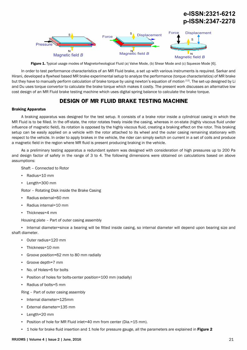
INTRODUCTIONMagnetorheological fluids, is a class of smart materials which undergoes a change in its apparent viscosity in presence of an
applied magnetic field. It consists of micron sized polarizable particles dispersed in a low viscosity carrier fluid. MR fluids were first developed by Jacob Rainbow (1949) at the US National Bureau of standards [1]. Their major constituents include: a carrier fluid, magnetizable particles and stabilizer additives. In presence of an external magnetic field, the magnetizable particles build chain like structures in the direction of magnetic field lines to undergo a rapid, reversible and controllable change in their yield stress and viscosity within milliseconds when a magnetic field is applied [2]. With such advantageous characteristics MR Fluids have gained attention in the last 20 years, when these fluids were commercially developed and devices such as suspension, dampers, brakes were designed. There are mainly three modes of MR Fluid operations, namely: shear mode, valve mode and squeeze mode depending on the required application [3-5]. In valve mode, also called flow mode, the fluid flows between two fixed walls and the magnetic field is normal to the flow direction. This mode is typical for linear damper applications [6]. The Squeeze mode has the fluid contained between two walls applying a compressive force on the fluid and a magnetic field normal to walls. It is used mainly for bearing applications. Shear mode mainly used in rotary application such as brakes and clutches, is characterized by the fluid constrained between two walls which are in relative motion and the magnetic field is normal to the wall direction which is explained in Figure 1. Various researchers have designed and tested MR Fluid brake, mostly operating in shear mode. Li and Du experimentally investigated torque characteristics of designed disc MR brake operating at low speeds. They found that brake torque increased steadily with the increment of magnetic field or rotary speed [7]. Huang, et al. presented theoretical design of a cylindrical MRF brake assuming annular space between circumference of disk and electromagnet filled with MR fluid, and calculated braking torque due to shearing of that MR fluid [8]. Assadsangabi in his work proposed a design of disk type brake in which new magnetic circuit of the brake caused the magnetic flux density to be concentrated at the end of the brake and therefore producing more braking torque [9]. Bydon described the construction and operation of Lord’s MR brake, which offers maximum 5.65 Nm torque at operating speed 1000 rpm [10]. Karakoc worked on multiple disk MR fluid brake and performed a finite element analysis to examine the resulting magnetic circuit and heat distribution within the MR brake configuration [11].
Design, Fabrication and Testing of Low Cost Magneto- Rheological Fluid Brake Testing Machine
Jain D*, Avchare KRDepartment of Mechanical Engineering, Maulana Azad National Institute of Technology (MANIT), India
Research Article
Received date: 25/02/2016Accepted date: 31/03/2016Published date: 07/04/2016
*For Correspondence
Jain D, Professor, Department of Mechanical Engineering, Maulana Azad National Institute of Technology (MANIT), India, Tel: 07554051000
Email: [email protected]
Keywords: MR Fluids; Magnetic circuit; Braking torque; pressure gauge
ABSTRACT
The main aim of this work was to design a low cost MR brake testing machine. We tried to achieve it by using digital spring balance to calculate the torque that reduces the cost of flywheel and digital cam that are needed to manipulate the torque otherwise.
e-ISSN:2321-6212 p-ISSN:2347-2278
21RRJOMS | Volume 4 | Issue 2 | June, 2016
Magnetic field B Magnetic field BMagnetic field B
Pressure
N
S Force Displacement DisplacementForce
NN
S
S
Figure 1. Typical usage modes of Magnetorheological Fluid (a) Valve Mode, (b) Shear Mode and (c) Squeeze Mode [6].
In order to test performance characteristics of an MR Fluid brake, a set up with various instruments is required. Sarkar and Hirani, developed a flywheel based MR brake experimental setup to analyze the performance (torque characteristics) of MR brake but they have to manually perform calculation of brake torque by using newton’s equation of motion [12]. The set-up designed by Li and Du uses torque convertor to calculate the brake torque which makes it costly. The present work discusses an alternative low cost design of an MR Fluid brake testing machine which uses digital spring balance to calculate the brake torque.
DESIGN OF MR FLUID BRAKE TESTING MACHINEBraking Apparatus
A braking apparatus was designed for the test setup. It consists of a brake rotor inside a cylindrical casing in which the MR Fluid is to be filled. In the off-state, the rotor rotates freely inside the casing, whereas in on-state (highly viscous fluid under influence of magnetic field), its rotation is opposed by the highly viscous fluid, creating a braking effect on the rotor. This braking setup can be easily applied on a vehicle with the rotor attached to its wheel and the outer casing remaining stationary with respect to the vehicle. In order to apply brakes in the vehicle, the rider can simply switch on current in a set of coils and produce a magnetic field in the region where MR fluid is present producing braking in the vehicle.
As a preliminary testing apparatus a redundant system was designed with consideration of high pressures up to 200 Pa and design factor of safety in the range of 3 to 4. The following dimensions were obtained on calculations based on above assumptions:
Shaft – Connected to Rotor
• Radius=10 mm
• Length=300 mm
Rotor – Rotating Disk inside the Brake Casing
• Radius external=60 mm
• Radius internal=10 mm
• Thickness=4 mm
Housing plate – Part of outer casing assembly
• Internal diameter=since a bearing will be fitted inside casing, so internal diameter will depend upon bearing size and shaft diameter.
• Outer radius=120 mm
• Thickness=10 mm
• Groove position=62 mm to 80 mm radially
• Groove depth=7 mm
• No. of Holes=6 for bolts
• Position of holes for bolts-center position=100 mm (radially)
• Radius of bolts=5 mm
Ring – Part of outer casing assembly
• Internal diameter=125mm
• External diameter=135 mm
• Length=20 mm
• Position of hole for MR Fluid inlet=40 mm from center (Dia.=15 mm).
• 1 hole for brake fluid insertion and 1 hole for pressure gauge, all the parameters are explained in Figure 2
e-ISSN:2321-6212 p-ISSN:2347-2278
22RRJOMS | Volume 4 | Issue 2 | June, 2016
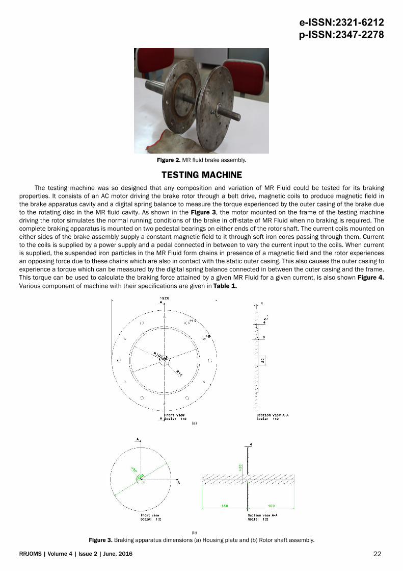
Figure 2. MR fluid brake assembly.
TESTING MACHINEThe testing machine was so designed that any composition and variation of MR Fluid could be tested for its braking
properties. It consists of an AC motor driving the brake rotor through a belt drive, magnetic coils to produce magnetic field in the brake apparatus cavity and a digital spring balance to measure the torque experienced by the outer casing of the brake due to the rotating disc in the MR fluid cavity. As shown in the Figure 3, the motor mounted on the frame of the testing machine driving the rotor simulates the normal running conditions of the brake in off-state of MR Fluid when no braking is required. The complete braking apparatus is mounted on two pedestal bearings on either ends of the rotor shaft. The current coils mounted on either sides of the brake assembly supply a constant magnetic field to it through soft iron cores passing through them. Current to the coils is supplied by a power supply and a pedal connected in between to vary the current input to the coils. When current is supplied, the suspended iron particles in the MR Fluid form chains in presence of a magnetic field and the rotor experiences an opposing force due to these chains which are also in contact with the static outer casing. This also causes the outer casing to experience a torque which can be measured by the digital spring balance connected in between the outer casing and the frame. This torque can be used to calculate the braking force attained by a given MR Fluid for a given current, is also shown Figure 4. Various component of machine with their specifications are given in Table 1.
(a)
(b)
Figure 3. Braking apparatus dimensions (a) Housing plate and (b) Rotor shaft assembly.Figure 3. Braking apparatus dimensions (a) Housing plate and (b) Rotor shaft assembly.

e-ISSN:2321-6212 p-ISSN:2347-2278
23RRJOMS | Volume 4 | Issue 2 | June, 2016
Figure 4. MR fluid brake testing machine after fabrication and assembly.
Serial no. Component Quantity Detailed Specification1 Motor 1 450 watt, single phase ac2 Belt 1 BX1053 Digital Spring Gauge 1 Capacity-10 kgf4 Pedal 1 Max. Current caring capacity-1.5 amp.5 Coils 2 No. of turns-500, max. field at center of disk-450 gauss(at 1.5 amp)6 Iron cores 2 Length=150mm, diameter=30mm7 Pedestal Bearing 2 UCP-201
Table 1. Component specification.
THEORITICAL CALCULATION OF TORQUEAs described above, when the pedal is pressed, current start flowing through coils, resulting in formation of chain of iron
particle inside cavity. Due to this action, outer casing of brake system experiences a torque that tries to rotate it in the direction of rotation of disk. But, the spring gauge, with one end attaches to outer casing and other to the base, does not allow it to rotate and hence measure the force experience by the casing.
If the force measure by spring gauge is F newton and R1 and R2 is the external radius of disk and position of spring gauge end attached to the casing, respectively then:
x*R1=F*R2
R1 - radius of disk=60mm
R2 - distance between center of disk and position of hole=100 mm
x=1.66F
Hence, the torque experienced by disk can be directly calculated from the reading of spring balance.
EXPERIMENT AND MATERIALSIn this work we have taken these four constitutes
• Magnetizable particles: Carbonyl iron powder (SIGMA ALDRICH 12310, 99 % purity and mean size of particle 150 μm)
• Base fluid: Silicone Oil (technical details)
• Surfactant: Tetra methyl ammonium hydroxide TMAH (technical details)
• Synthetic oil suspension: Soya Lecithin (technical details )
It has been found that torque mainly depends upon the fraction of iron particle inside MR Fluid. Hence, in this work 4 samples of following compositions were prepared:
• MRF 1: 5% (by vol.) of iron particle ,4% soya lecithin, 2.75% TMAH and remaining silicon oil,
• MRF 2: 10% (by vol.) of iron particle ,4% soya lecithin, 2.75% TMAH and remaining silicon oil,
• MRF 3: 15% (by vol.) of iron particle ,4% soya lecithin, 2.75% TMAH and remaining silicon oil,
• MRF 4: 20% (by vol.) of iron particle ,4% soya lecithin, 2.25% TMAH and remaining silicon oil.

e-ISSN:2321-6212 p-ISSN:2347-2278
24RRJOMS | Volume 4 | Issue 2 | June, 2016
For preparation of fluid following procedure is used:
MR fluid has been prepared by the method of mechanical mixing.
• Coating of CI particle: CI particles coated by lecithin by mechanical stirring for 60 min. at rpm of 600.
• Tetra methyl ammonium hydroxide poured in that and stirred for 90 min. at rpm of 600.
• Silicon oil taken in vessel and stirred meanwhile coated CI particles added gradually (5 gram/10 min.) and then stirred for next 6 hours.
TESTING AND OBSERVATIONThe above prepared 4 samples were filled inside the cavity one by one and brake torque was calculated for different
values of motor speed and current. All the experiment was performed at constant 1000 rpm. Multiple readings of torque at different current ratings is calculated and then mean average is taken to reduce the systematic errors. The data obtained from the experiment are plotted in Figure 5.
.3 amp .6 amp .9 amp 1.2 amp.
1.4
1.2
1
0.8
0.6
0.4
0.2
0
MRF1
MRF2
MRF3
MRF4
Figure 5. Brake torque “x” vs. Current (at 1000 rpm).
RESULT AND DISCUSSIONSFrom the experiment conducted to calculate the torque, the maximum torque obtained is 1.2 newton-meters from MRF-
4 sample at 1.2 amperes current and 450 gauss of magnetic field at 1000 rpm. The brake torque shows slightly linear trends for MRF 1 AND MRF 2 sample that has been attributed to the fact that since the fraction of iron particle is low and hence chain formation is not adequate due to vibrations and other dynamic factors.
CONCLUSIONThe main aim of this work was to design a low cost MR brake testing machine. We have achieved it by using digital spring
balance to calculate the torque that reduces the cost of flywheel and digital cam that are needed to manipulate the torque otherwise. A completely new approach is used to create the magnetic field inside the cavity of brakes. Iron cores are used to concentrate the magnetic field lines so that brake torque can be increased. Finally, different samples of MR fluids are prepared in the laboratory and brake torque is calculated by filling them in brake apparatus. This machine can be used for comparing the torque characteristics of different MR fluids.
REFERENCES1. Roszkowski A, et al. Testing Viscosity of MR Fluid in Magnetic Field. Measurement science review 2008;8;02-25.
2. Ashour O and Craig A. Magneto-rheological fluids: materials, characterization, and devices. J Int Mater Syst Struct1996;7:123-130.
3. Mark R, et al. Properties and Applications of Commercial Magnetorheological Fluids. Journal of Intelligent Material Systems and Structures 1999;10:1 5-13.
4. Fernando D. Goncalves, Characterizing the Behavior of Magnetorheological Fluids at High Velocities and High Shear Rates. International Journal of Modern Physics B 2005;19:21-40.
5. Turczyn R and Kciuk M. preparation and study of modern magnetorhelogical fluid. JAMME journal 2008;27:25-36.

e-ISSN:2321-6212 p-ISSN:2347-2278
25RRJOMS | Volume 4 | Issue 2 | June, 2016
6. Bolter R and Janocha, H. Design rules for MR fuid actuators in different working modes. In Proceedings of the SPIE Conference of the International Society for Optical Engineers 1997;3045:148-159.
7. Li WH and Du H. Design and Experimental Evaluation of a Magnetorheological Brake. Int J Adv Manuf Technol 2003;21:508-15.
8. Huang J, et al.Analysis and design of a cylindrical magnetorheological fluid brake. J Mater Process Technol 2002;129:559-62.
9. Assadsangabi B. Optimization and design of disk type MR brake, International Journal of Automotive Technology 2011;12:921-932.
10. Bydon S. Construction and operation of magnetorheological rotary brake. Archiwum Process Control Club 2002;20:12-59.
11. Karakoc K, et al. Design considerations for an automotive magnetorheological brake. Mechatronics 18 2008;8:434-447.
12. Synthesis and Characterization of Antifriction Magnetorheological Fluids for Brake. Defense Science Journal 2013;2:408-412.


