Embed Size (px)
Citation preview
Design Envelope4200H & 4280End Suction HorizontalPumping Units Installation and operating instructions
File No: 94.85Date: february 15, 2016 Supersedes: newDate: new

5 . 4 Programming 195 . 4 .1 Parameter selection 195 . 4 . 2 Changing data 20
6.0 Sensorless operation 206.1 Default operating mode – 2 1
Quadratic pressure control6.1 .1 Settings for quadratic
(control curve) pressure control 21
6. 2 Constant pressure control 2 16. 2 .1 Settings for constant
Pressure control 226.3 Changing control modes 22
6.3 .1 Change to external sensor control 22
6.3 . 2 Change to open loop ( ips/bas/bms) control 22
6.3 .3 Change to sensorless control 22
6. 4 Special Application Procedures 226. 4 .1 2-way bypass valve
control 226. 4 . 2 Maximum flow control 246. 4 .3 Flow limit breach closes
a dry-contact relay 256. 4 . 4 Minimum flow control 256. 4 .5 Multiple sensor control 266. 4 .6 Motor pre-heat
application 276. 4 .7 Start standby pump by
falling sensor reading 296. 4 .8 Start standby by system
contact opening 307.0 Warnings & alarms 32
7.1 Fault messages 328.0 Acoustic noise & vibration 35table 1 Alarm/warning code list 36table 2 ivs 102 parameter settings 38
contents1.0 Introduction 4
1 .1 Instructions for safe use 41 . 2 Temperature 41 .3 Noise levels 41 . 4 Vibration levels 41 .5 Storage 51 .6 Uncrating 51 .7 Handling Design Envelope 4200h
& 4280 units 52.0 Installation 6 2 .1 Location 6
2. 2 Installation 62.3 Pump piping – general 72. 4 Alignment 72.5 Starting pump 72.6 General care 82.7 Lubrication 82.8 System cleanliness 8
3 .0 Integrated controls 93 .1 Enclosure rating 93 . 2 Ambient temperature 9
4 .0 Electrical installation 9 4 .1 Ground leakage current 9
4 . 2 Start/stop of pump 94 .3 Additional motor protection 94 . 4 Supply voltage 94 .5 Supply fusing 104 .6 Grounding & it mains 104 .7 Relay connections 1 14 .8 Electrical installation
& control connections 134 .8.1 Access to terminals 144 .8. 2 Control terminals 144 .8.3 Connection examples 15
5 .0 Programming, monitoring & diagnotics 175 .1 glcp functions & operation 175 . 2 Indicator lights (leds) 185 .3 Control keys 18
installation & operating instructions
Design Envelope 4200h & 4280End Suction Horizontal Pumping Units
4
1.0 introduction
This document contains specific information regarding the safe installation, operating and maintenance of the Armstrong Design Envelope pumps and should be read and understood by installing, operating and maintenance personnel. The equip-ment supplied has been designed and constructed to be safe and without risk to health and safety when properly installed, operated and maintained. The instructions following must be strictly adhered to. If clarification is needed on any point please contact Armstrong quoting the equipment serial number.
1 .1 instructions for safe use
No installation of this equipment should take place unless this document has been studied and under-stood. Handling, transportation and installation of
this equipment should only undertaken by trained personnel with proper use of lifting equipment. See later diagrams for lift-ing advice. Refer to the pump nameplate for pump speed, pres-sure and temperature limitations. The limits stated must not be exceeded without written permission from Armstrong.
1 . 2 temperature
Install the unit with adequate access for routine maintenance. Adequate space, particularly at the fan inlet 2" (50 mm), is necessary to facilitate airflow.
Where several units are installed in close proximity, care must be taken to ensure that there is no re-circulation of exhausted warm air.
Where under normal operating conditions the limit of 68°c/155°f (Restricted Zone) for normal touch, or 80°c/176°f (Unrestricted Zone) for unintentional touch, may be expe-rienced, steps should be taken to minimize contact or warn operators/users that normal operating conditions will be ex-ceeded. In certain cases where the temperature of the pumped liquid exceeds the above stated temperature levels, pump casing temperatures may exceed 100°c/212°f and not with-standing pump insulation techniques appropriate measures must be taken to minimize risk for operating personnel. The ambient temperature for standard motors must be no greater than 40°c/104°f.
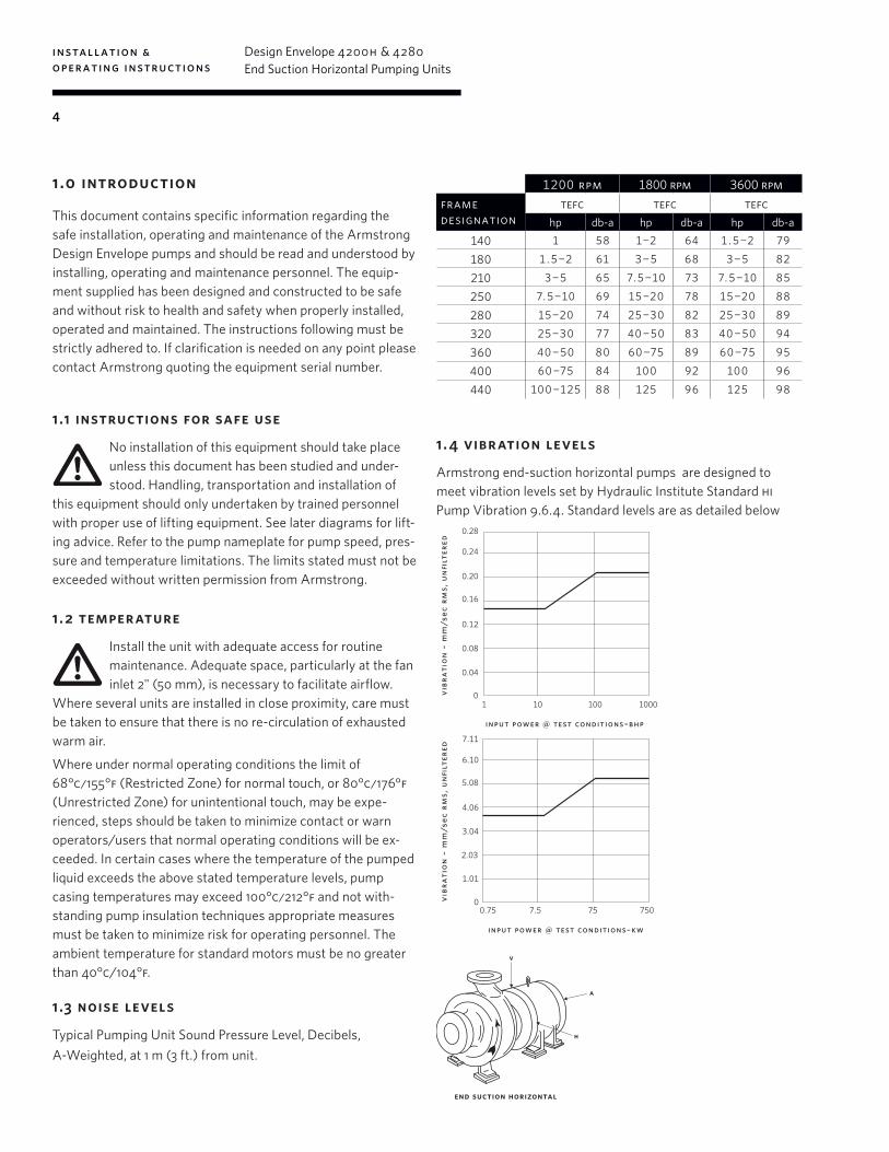
1 .3 noise levels
Typical Pumping Unit Sound Pressure Level, Decibels, A-Weighted, at 1 m (3 ft.) from unit.
1200 rpm 1800 rpm 3600 rpmframe designation
tefc tefc tefchp db-a hp db-a hp db-a
140 1 58 1-2 64 1.5-2 79
180 1.5-2 61 3-5 68 3-5 82
210 3-5 65 7.5-10 73 7.5-10 85
250 7.5-10 69 15-20 78 15-20 88
280 15-20 74 25-30 82 25-30 89
320 25-30 77 40-50 83 40-50 94
360 40-50 80 60-75 89 60-75 95
400 60-75 84 100 92 100 96
440 100-125 88 125 96 125 98
1 . 4 vibration levels
Armstrong end-suction horizontal pumps are designed to meet vibration levels set by Hydraulic Institute Standard hi Pump Vibration 9.6.4. Standard levels are as detailed below
7.11
6.10
5.08
7.5 75 7500.75
4.06
3.04
2.03
1.01
0
input power @ test conditions–kw
vibr
atio
n –
mm/s
ec r
ms,
un
filt
ered
0.28
0.24
0.20
10 100 10001
0.16
0.12
0.08
0.04
0
input power @ test conditions–bhp
vibr
atio
n –
mm/s
ec r
ms,
un
filt
ered
v
a
h
end suction horizontal
installation & operating instructions
Design Envelope 4200h & 4280End Suction Horizontal Pumping Units
5
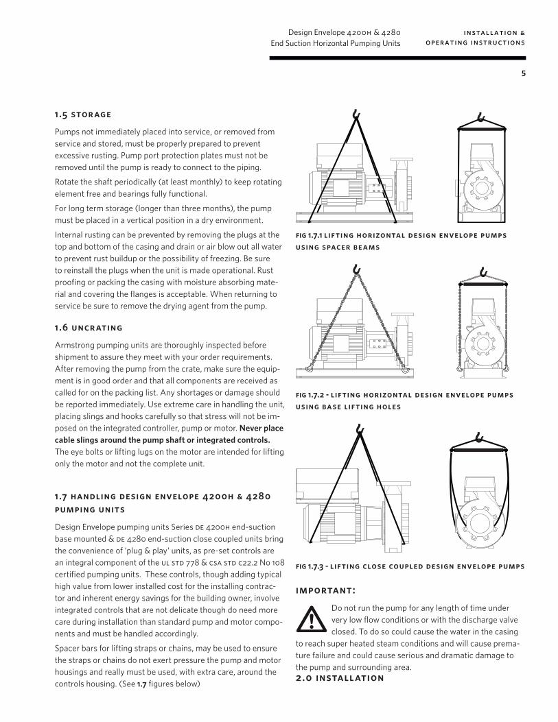
1.5 storage
Pumps not immediately placed into service, or removed from service and stored, must be properly prepared to prevent excessive rusting. Pump port protection plates must not be removed until the pump is ready to connect to the piping.
Rotate the shaft periodically (at least monthly) to keep rotating element free and bearings fully functional.
For long term storage (longer than three months), the pump must be placed in a vertical position in a dry environment.
Internal rusting can be prevented by removing the plugs at the top and bottom of the casing and drain or air blow out all water to prevent rust buildup or the possibility of freezing. Be sure to reinstall the plugs when the unit is made operational. Rust proofing or packing the casing with moisture absorbing mate-rial and covering the flanges is acceptable. When returning to service be sure to remove the drying agent from the pump.
1 .6 uncrating
Armstrong pumping units are thoroughly inspected before shipment to assure they meet with your order requirements. After removing the pump from the crate, make sure the equip-ment is in good order and that all components are received as called for on the packing list. Any shortages or damage should be reported immediately. Use extreme care in handling the unit, placing slings and hooks carefully so that stress will not be im-posed on the integrated controller, pump or motor. Never place cable slings around the pump shaft or integrated controls. The eye bolts or lifting lugs on the motor are intended for lifting only the motor and not the complete unit.
1 .7 handling design envelope 4200h & 4280 pumping units
Design Envelope pumping units Series de 4200h end-suction base mounted & de 4280 end-suction close coupled units bring the convenience of ‘plug & play’ units, as pre-set controls are an integral component of the ul std 778 & csa std c22.2 No 108 certified pumping units. These controls, though adding typical high value from lower installed cost for the installing contrac-tor and inherent energy savings for the building owner, involve integrated controls that are not delicate though do need more care during installation than standard pump and motor compo-nents and must be handled accordingly.
Spacer bars for lifting straps or chains, may be used to ensure the straps or chains do not exert pressure the pump and motor housings and really must be used, with extra care, around the controls housing. (See 1.7 figures below)
fig 1.7.1 lifting horizontal design envelope pumps using spacer beams
fig 1.7.2 - lifting horizontal design envelope pumps using base lifting holes
fig 1.7.3 - lifting close coupled design envelope pumps
important: Do not run the pump for any length of time under very low flow conditions or with the discharge valve closed. To do so could cause the water in the casing
to reach super heated steam conditions and will cause prema-ture failure and could cause serious and dramatic damage to the pump and surrounding area. 2.0 installation
installation & operating instructions
Design Envelope 4200h & 4280End Suction Horizontal Pumping Units
6
2.1 location
In open systems, locate the unit as close as practical to the liquid being pumped, with a short, direct suction pipe. Ensure adequate space is left above and around the unit for operation, maintenance, service and inspection of parts.
In closed systems, where possible, the pumps should be in-stalled immediately downstream of the expansion tank /make-up connection. This is the point of zero pressure change and is necessary for effective pump operation. Do not install more than one expansion tank connection into any closed hydronic system. Electric motor driven pumps should not be located in damp or dusty location without special protection.
Airflow into the motor and/or motor fan should not be ob-structed.
It is good practice to leave sufficient space around equipment for maintenance and service needs. If the Design Envelope controls are supplied with integral disconnect switches, 36 ins / 1 meter clearance may be required in front of the controls to meet local electrical codes.
2. 2 installation
The following text and illustrations are offered as general sug-gestions for the preparation of a satisfactory foundation.
Foundation should be sufficiently substantial to absorb any vibration and permanently support the baseplate at all points. This is essential in maintaining the alignment of a direct coupled unit.
Horizontal Design Envelope units are inherently soft start and operate the majority of the time at lower than synchronous speed. This means that the huge (About 3-times the weight of the pumping unit) inertia bases are not required and much more simple vibration isolation may be used.
If the unit is to be mounted on fabricated steel work or similar structure, the unit should be set over, or as near as possible to, the supporting beams or walls and to be so supported that the baseplate cannot be distorted by any yielding or springing of the structure or base.
The (4) corner holes should be used as a minimum. All (6) holes can be used on larger bases. Secure evenly spaced straps placed under the baseplate is also acceptable for lifting the entire unit.
Horizontal Design Envelope pumping units are supplied with rigid split couplings (DE 4200H) or are close-coupled (DE 4280), as such no alignment is necessary in the field.
Place pumping unit on the foundation and insert metal wedges
on either side of the foundation bolts under base plate. Leave approximately 0.75 ins (19mm) space if grouting.
Carefully level the unit by adjusting the wedges until base is supported in a level position
With the proper gauge, check suction and discharge flanges of the pump for proper positioning.
When the baseplate is completely level, the foundation bolts should be tightened evenly and firmly.
2. 2 .1 grouting
Armstrong’s fabricated steel base plates, as supplied with 4200h Design Envelope pumps, are manufactured to ansi/hi 1.3.5 rigidity standards for free-standing base plates. As such, no grouting in place is necessary for the base plate to hold shaft alignment of any Armstrong base mounted pumping unit. End-suction horizontal base mounted Design Envelope pumping units are supplied with rigid couplings which need no re-alignment at installation or following seal service. Thus grouting is not necessary; though the following instructions are for installers who still wish to also secure the base in place with grout:
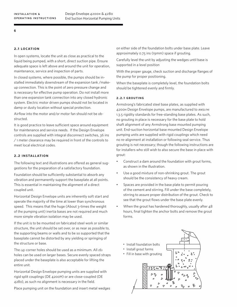
• Construct a dam around the foundation with grout forms, as shown in the illustration.
• Use a good mixture of non-shrinking grout. The grout should be the consistency of heavy cream.
• Spaces are provided in the base plate to permit pouring of the cement and stirring. Fill under the base completely, stirring to assure proper distribution of the grout. Check to see that the grout flows under the base plate evenly.
• When the grout has hardened thoroughly, usually after 48 hours, final tighten the anchor bolts and remove the grout forms.
• Install foundation bolts • Install grout forms • Fill in base with grouting
installation & operating instructions
Design Envelope 4200h & 4280End Suction Horizontal Pumping Units
7
2.3 pump piping – general
Never connect a pump to piping, unless extra care is taken to measure and align the piping flanges well. Always start piping from pump.
Use as few bends as possible and preferably long radius el-bows.
Do not use flexible connectors on the suction or discharge of a vertical in-line pump, unless the pump is rigidly mounted to a foundation.
Ensure piping exerts no strain on pump as this could distort the casing causing breakage or early failure due to pump misalignment.
All connecting pipe flanges must be square to the pipework and parallel to the pump flanges.
Suction and discharge pipes may be increased or decreased at pump nozzle to suit pump capacity and particular conditions of installation. Use eccentric reducers on suction connection with flat side uppermost.
Layout the suction line with a continual rise towards the pump without high points, thus eliminating possibility of air pockets that may prevent the pump from operating effectively.
A strainer of three or four times the area of the suction pipe, installed in the suction line, will prevent the entrance of foreign materials into the pump. V" (3 mm) diameter perforations in the strainer is typical.
In open systems, test suction line for air leaks before starting; this becomes essential with long suction line or static lift.
Install, at the pump suction, a straight pipe of a length equiva-lent to four or six times its diameter; this becomes essential when handling liquids above 120°f (49°c). Armstrong suction guides may be used in place of the straight pipe run and in-line strainer.
Install an isolation valve in both suction and discharge lines on flooded suction application; these valves are used primarily to isolate the pump for inspection or repair.
Install a non-slam non-return check valve in discharge line between pump and isolation valve to protect pump from exces-sive back pressure and to prevent water running back through the pump in case of driver failure on open systems. Armstrong Flo-Trex valves may be used in place of isolation valves and non-return check valves. Flo-Trex valves use plug & disk design which may also be used for throttling excessive system flow for constant speed pumps and, if necessary, for variable speed pumps. Do not throttle variable speed pumps unless absolutely necessary.
2. 4 alignment
Design Envelope 4200h units are accurately aligned at the factory prior to being shipped and do not need re-aligning when installed.
Alignment on a Design Envelope 4200h unit may be verified by assuring an equal and parallel gap between coupling halves on both sides of the coupling.
operation
2.5 starting pump
Ensure that the pump turns freely by hand, or with some gentle mechanical help such as a strap or Allen key in the shaft hole or coupling bolt head.
Ensure that all protective guarding is securely fixed in position.
The pump must be fully primed on start up. Fill the pump casing with liquid and rotate the shaft by hand to remove any air trapped in the impeller. On Design Envelope 4200h any air trapped in the casing as the system is filled must be removed by the manual air vent in the seal flush line. Ensure entrained air is removed from Design Envelope 4200h pumps, prior to starting, through the air vent on the seal flush line. Open vent until clear of air.
Bump or energize the motor momentarily and check that the rotation corresponds with the directional arrow on the pump casing (clockwise when viewed from drive end.).
Start the pump with the discharge valve closed and the suction valve open, then gradually open the discharge valve when the motor is at operating speed. The discharge valve may be cracked or open slightly at start up to help eliminate trapped air.
When stopping the pump: Close the discharge valve and de-energize the motor.
Do not run the pump against a closed discharge valve for an extended period of time (a few minutes maximum.)
Should the pump be noisy or vibrate on start-up a common reason is overstated system head. Check this by calculating the pump operating head by deducting the suction pressure gauge value from the discharge gauge reading. Convert the result into the units of the pump head as stated on the pump nameplate and compare the values. The system designer or operator should be made aware of this soon as some adjustment may be required to the drive settings to make the pump suitable for the system as installed.
installation & operating instructions
Design Envelope 4200h & 4280End Suction Horizontal Pumping Units
8
Check rotation arrow prior to operating the unit. The rotation of all Armstrong end-suction commercial pumping units is clock-wise when viewed from the drive end. (Looking from behind the motor).
2.6 general care
Armstrong end-suction commercial pumps are built to operate without periodic maintenance, other than motor lubrication on larger units. A systematic inspection made at regular intervals, will ensure years of trouble-free operation, giving special atten-tion to the following:
• Keep unit clean • Keep moisture, refuse, dust or other loose particles away
from the pump and cooling openings of the motor and controller.
• Avoid operating the unit in overheated surroundings (Above 100°f/40°c).
warning: Whenever any service work is to be performed on a pumping unit, disconnect the power source to the driver, lock it off and tag with the reason. Any
possibility of the unit starting while being serviced must be eliminated.
If mechanical seal environmental accessories are installed, en-sure water is flowing through the sight flow indicator and that filter cartridges are replaced as recommended. (See Armstrong files 43.85 and 43.86 for seal environmental instructions).
2.7 lubrication
Pump
Lubrication is not required. There are no bearings in the pump that need external lubrication service.
Motor
Follow the lubrication procedures recommended by the motor manufacturer. Many small and medium sized motors are per-manently lubricated and need no added lubrication. Generally if there are grease fittings evident the motor needs periodic lubrication. None if not.
Check the lubrication instructions supplied with the motor for the particular frame size indicated on the motor nameplate.
Mechanical Seal
Mechanical seals require no special attention. The mechanical seal is fitted with a flush line. The seal is flushed from discharge of the pump casing on Design Envelope 4200h pumps.
The Design Envelope 4200h pump is flushed from the pump discharge because the mechanical seal chamber is isolated from the liquid in the pump by a throttle bushing. Because the seal chamber is isolated, seal environmental controls such as filters and separators, when installed in the Design Envelope 4200h flush line are very effective, as only the seal chamber needs cleansing, and will prolong seal life in hvac systems.
Do not run the pump unless properly filled with water as the mechanical seals need a film of liquid between the faces for proper operation.
Mechanical seals may ‘weep’ slightly at start-up. Allow the pump to continue operating for several hours and the mechani-cal seal to ‘seat’ properly prior to calling for service personnel.
The following Armstrong files are available for mechanical seal replacement instructions:
• Series 4300: tc Motor Frame – File 43.88
• Series 4380: File 43.81
2.8 system cleanliness
Before starting the pump the system must be thoroughly cleaned, flushed and drained and replenished with clean liquid.
Welding slag and other foreign materials, stop leak and clean-ing compounds and improper or excessive water treatment are all detrimental to the pump internals and sealing arrangement.
Proper operation cannot be guaranteed if the above conditions are not adhered to.
note:
Particular care must be taken to check the following before the pump is put into operation:
a Pump primed?
b Rotation ok?
c Lubrication ok?
d Pipe work properly supported?
e Voltage supply ok?
f Is the system clean?
g Is the area around the pump clean?
warr anty
Does not cover any damages to the equipment resulting from failure to observe the above precautions. Refer to Armstrong General Terms and Warranty sheet. Contact your local Arm-strong representative for full information.
installation & operating instructions
Design Envelope 4200h & 4280End Suction Horizontal Pumping Units
9
3.0 integrated controls
3 .1 enclosure rating
The standard enclosure rating for Design Envelope 4200h & 4280 integrated controls is ul type 12 for indoor applications. If the pump is to be installed in a
wet or dusty environment then a higher enclosure rating may be required (contact Armstrong).
3. 2 ambient temperature
To avoid the ivs102 unit getting overheated, the ambient temperature is not to exceed 133°f (45°c) av-erage daily temperature. Operating in higher ambient temperatures will require derating of the inverter.
4 .0 electrical installation
All electrical connections should be carried out by a qualified and authorized electrician in accordance with local site regulations and the latest issue of the
iee regulations.
safety, risk of deathBefore removing the inverter cover, the system must be disconnected from the mains supply. After switch-ing off, wait for at least 15 minutes for the capacitors
to discharge before opening the cover.
cautionHigh voltage testing (Megging) of the motor/inverter may cause damage to the electronic components and therefore should not be carried out.
4 .1 ground leak age current
Ground leakage current is primarily caused by the capacitance between motor phases and the motor frame. The rfi filter contributes additional leakage
current, as the filter circuit is connected to ground through capacitors.
The size of the leakage current to the ground depends on the following factors, in order of priority:
1 Switching frequency
2 Motor grounded on site or not
The leakage current is of importance to safety during handling/operation of the pump if (by mistake) the on-board inverter has not been grounded.
Since the leakage current is >3.5ma (approx 4-20ma), rein-forced Grounding must be established which is required if en 50178 is to be complied with. Never use elcb relays that are not suitable for dc fault currents (type a).
If elcb relays are used, they must be:
• Suitable for protecting equipment with a direct current con-tent (dc) in the fault current (three-phase bridge rectifier)
• Suitable for power-up with short charging current to Ground
• Suitable for a high leakage current
4 . 2 start / stop of pump
The number of starts/stops via the mains voltage must not exceed one-time per minute.
If a higher number of starts/stops is required then the start/stop digital input must be used (mains voltage directly con-nected). This is the preferred method of starting and stopping Pumps.
The three phase mains must be isolated before performing maintenance of the pump.
4 .3 additional motor protection
With the exception of supply fuses / mcb’s to protect the installation (for over-current and short-circuit protection), no additional overload or over-tempera-
ture protection is required (i.e. thermal overloads). Protection features include:
• Mains phase loss• Over voltage• Under voltage• Electronic thermal motor protection• Short circuit on motor terminals• Ground fault on motor terminals• Over temperature
4 . 4 supply voltage
The supply voltage details can be found on the ivs102 name-plate. Please ensure that the unit is suitable for the electrical supply on which it is to be used. The mains supply for pumps is as follows:
1 × 200 -240v ± 10%
3 × 200 -240v ± 10%
3 × 380 -480v ± 10%
3 × 525- 600v ± 10%
Supply frequency - 50/60Hz
installation & operating instructions
Design Envelope 4200h & 4280End Suction Horizontal Pumping Units
10
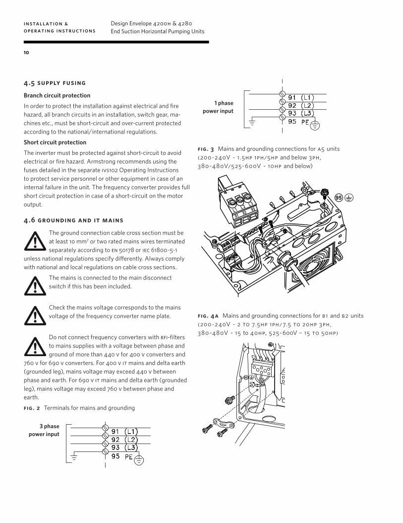
4 .5 supply fusing
Branch circuit protection
In order to protect the installation against electrical and fire hazard, all branch circuits in an installation, switch gear, ma-chines etc., must be short-circuit and over-current protected according to the national/international regulations.
Short circuit protection
The inverter must be protected against short-circuit to avoid electrical or fire hazard. Armstrong recommends using the fuses detailed in the separate ivs102 Operating Instructions to protect service personnel or other equipment in case of an internal failure in the unit. The frequency converter provides full short circuit protection in case of a short-circuit on the motor output.
4 .6 grounding and it mains
The ground connection cable cross section must be at least 10 mm2 or two rated mains wires terminated separately according to en 50178 or iec 61800-5-1
unless national regulations specify differently. Always comply with national and local regulations on cable cross sections.
The mains is connected to the main disconnect switch if this has been included.
Check the mains voltage corresponds to the mains voltage of the frequency converter name plate.
Do not connect frequency converters with rfi-filters to mains supplies with a voltage between phase and ground of more than 440 v for 400 v converters and
760 v for 690 v converters. For 400 v it mains and delta earth (grounded leg), mains voltage may exceed 440 v between phase and earth. For 690 v it mains and delta earth (grounded leg), mains voltage may exceed 760 v between phase and earth.
fig. 2 Terminals for mains and grounding
3 phase power input
2. Place plug connector 91, 92, 93 from the accessory bag onto the terminals labelled MAINS at the bottom of the frequency converter.
3. Connect mains wires to the mains plug connector.
The earth connection cable cross section must be at least 10 mm2 or 2 rated mains wires terminated separately according to EN 50178.
The mains connection is fitted to the main switch if this is included.
NB!
Check that mains voltage corresponds to the mains voltage of the frequency converter name plate.
IT Mains
Do not connect 400 V frequency converters with RFI-filters to mains supplies with a voltage between phase and earth of more than
440 V.
For IT mains and delta earth (grounded leg), mains voltage may exceed 440 V between phase and earth.
Illustration : Terminals for mains and earthing.
5 How to Install VLT® AQUA Drive Design Guide
122 MG.20.N5.02 - VLT® is a registered Danfoss trademark
5
1 phase power input
fig. 3 Mains and grounding connections for a5 units (200 -240V - 1 .5hp 1ph/5hp and below 3ph, 380 -480V/525- 600V - 10hp and below)
Page 10 of 26
Figure 3. Mains and Grounding Connections for A5 Units (200-240V - 5HP and Below, 380-480V / 525-600V - 10HP and Below)
4.6 GROUNDING AND IT MAINS
The ground connection cable cross section must be at least 10 mm 2 or 2 rated mains wires terminated sepa-
rately according to EN 50178 or IEC 61800-5-1 unless national regulations specify dierently. Always comply with national and local regulations on cable cross sections.
The mains is connected to the main disconnect switch if this has been included.
NB! Check the mains voltage corresponds to the mains volt-age of the frequency conv erter name plate.
IT Mains Do not connect frequency converters with RFI-lters to mains supplies with a voltage between phase and
earth of more than 440 V for 400 V converters and 760 V for 690 V converters. For 400 V IT mains and delta earth (grounded leg), mains voltage may exceed 440 V between phase and earth. For 690 V IT mains and delta earth (grounded leg), mains voltage may exceed 760 V between phase and earth.
Figure 2. Terminals for Mains and Grounding
Figure 4b. Mains and Grounding Connections for C1 and C2 units (200-240V - 25 to 60HP, 380-480V - 50 to 125HP, 525-600V - 60 to 125HP)
Figure 4a. Mains and Grounding Connections for B1 and B2 Units (200-240V - 7.5 to 20HP, 380-480V - 15 to 40HP, 525-600V - 15 to 50HP)
95
91L1
92L2
93L3
95
95
fig. 4 a Mains and grounding connections for b1 and b2 units (200 -240V - 2 to 7.5hp 1ph/ 7.5 to 20hp 3ph, 380 -480V - 15 to 40hp, 525- 600V – 15 to 50hp)
Page 10 of 26
Figure 3. Mains and Grounding Connections for A5 Units (200-240V - 5HP and Below, 380-480V / 525-600V - 10HP and Below)
4.6 GROUNDING AND IT MAINS
The ground connection cable cross section must be at least 10 mm 2 or 2 rated mains wires terminated sepa-
rately according to EN 50178 or IEC 61800-5-1 unless national regulations specify dierently. Always comply with national and local regulations on cable cross sections.
The mains is connected to the main disconnect switch if this has been included.
NB! Check the mains voltage corresponds to the mains volt-age of the frequency conv erter name plate.
IT Mains Do not connect frequency converters with RFI-lters to mains supplies with a voltage between phase and
earth of more than 440 V for 400 V converters and 760 V for 690 V converters. For 400 V IT mains and delta earth (grounded leg), mains voltage may exceed 440 V between phase and earth. For 690 V IT mains and delta earth (grounded leg), mains voltage may exceed 760 V between phase and earth.
Figure 2. Terminals for Mains and Grounding
Figure 4b. Mains and Grounding Connections for C1 and C2 units (200-240V - 25 to 60HP, 380-480V - 50 to 125HP, 525-600V - 60 to 125HP)
Figure 4a. Mains and Grounding Connections for B1 and B2 Units (200-240V - 7.5 to 20HP, 380-480V - 15 to 40HP, 525-600V - 15 to 50HP)
95
91L1
92L2
93L3
95
95
installation & operating instructions
Design Envelope 4200h & 4280End Suction Horizontal Pumping Units
11
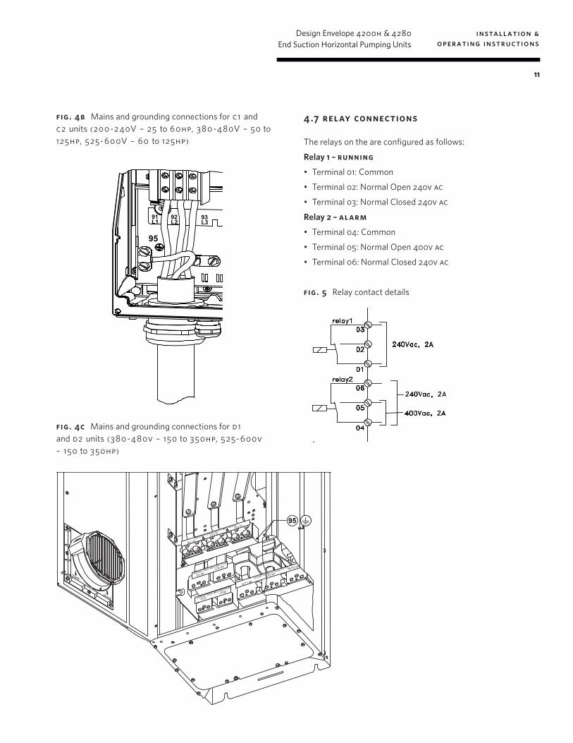
fig . 4b Mains and grounding connections for c 1 and c2 units (200 -240V – 25 to 60hp, 380 -480V – 50 to 125hp, 525- 600V – 60 to 125hp)
Page 10 of 26
Figure 3. Mains and Grounding Connections for A5 Units (200-240V - 5HP and Below, 380-480V / 525-600V - 10HP and Below)
4.6 GROUNDING AND IT MAINS
The ground connection cable cross section must be at least 10 mm 2 or 2 rated mains wires terminated sepa-
rately according to EN 50178 or IEC 61800-5-1 unless national regulations specify dierently. Always comply with national and local regulations on cable cross sections.
The mains is connected to the main disconnect switch if this has been included.
NB! Check the mains voltage corresponds to the mains volt-age of the frequency conv erter name plate.
IT Mains Do not connect frequency converters with RFI-lters to mains supplies with a voltage between phase and
earth of more than 440 V for 400 V converters and 760 V for 690 V converters. For 400 V IT mains and delta earth (grounded leg), mains voltage may exceed 440 V between phase and earth. For 690 V IT mains and delta earth (grounded leg), mains voltage may exceed 760 V between phase and earth.
Figure 2. Terminals for Mains and Grounding
Figure 4b. Mains and Grounding Connections for C1 and C2 units (200-240V - 25 to 60HP, 380-480V - 50 to 125HP, 525-600V - 60 to 125HP)
Figure 4a. Mains and Grounding Connections for B1 and B2 Units (200-240V - 7.5 to 20HP, 380-480V - 15 to 40HP, 525-600V - 15 to 50HP)
95
91L1
92L2
93L3
95
95
fig. 4c Mains and grounding connections for d1 and d2 units (380 -480v – 150 to 350hp, 525- 600v – 150 to 350hp)
Page 11 of 26
4.7 RELAY CONNECTIONS The relays on the IVS are congured as follows: Relay 1 - RUNNING Terminal 01: Common Terminal 02: Normal Open 240V AC Terminal 03: Normal Closed 240V AC Relay 2 - ALARM Terminal 04: Common Terminal 05: Normal Open 400V AC Terminal 06: Normal Closed 240V AC
Figure 5. Relay Contact Details
Figure 4c. Mains and Grounding Connections for D1 and D2 units (380-480V - 150 to 350HP, 525-600V - 150 to 350HP)
95
4 .7 relay connections
The relays on the are configured as follows:
Relay 1 – running
• Terminal 01: Common
• Terminal 02: Normal Open 240v ac
• Terminal 03: Normal Closed 240v ac
Relay 2 – alarm
• Terminal 04: Common
• Terminal 05: Normal Open 400v ac
• Terminal 06: Normal Closed 240v ac
fig. 5 Relay contact details
Page 11 of 26
4.7 RELAY CONNECTIONS The relays on the IVS are congured as follows: Relay 1 - RUNNING Terminal 01: Common Terminal 02: Normal Open 240V AC Terminal 03: Normal Closed 240V AC Relay 2 - ALARM Terminal 04: Common Terminal 05: Normal Open 400V AC Terminal 06: Normal Closed 240V AC
Figure 5. Relay Contact Details
Figure 4c. Mains and Grounding Connections for D1 and D2 units (380-480V - 150 to 350HP, 525-600V - 150 to 350HP)
95
installation & operating instructions
Design Envelope 4200h & 4280End Suction Horizontal Pumping Units
12
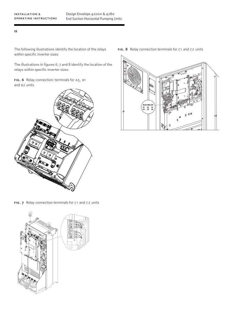
The following illustrations identify the location of the relays within specific inverter sizes:
The illustrations in figures 6, 7 and 8 identify the location of the relays within specific inverter sizes:
fig. 6 Relay connection: terminals for a5 , b1 and b2 units
Page 12 of 26
The following illustrations identify the location of the relays within spec ic inverter sizes: The illustrations in gures 6, 7 and 8 identify the locati on of the relays within specic inverter sizes:
Figure 7. Relay Connection Terminals for C1 and C2 Units Figure 6. Relay Connection Terminals for A5, B1 and B2 Units
Figure 8. Relay Connection Terminals for D1 and D2 units
01 02 0304 05 06
AUX RELAY
fig. 7 Relay connection terminals for c 1 and c2 units
Page 12 of 26
The following illustrations identify the location of the relays within spec ic inverter sizes: The illustrations in gures 6, 7 and 8 identify the locati on of the relays within specic inverter sizes:
Figure 7. Relay Connection Terminals for C1 and C2 Units Figure 6. Relay Connection Terminals for A5, B1 and B2 Units
Figure 8. Relay Connection Terminals for D1 and D2 units
01 02 0304 05 06
AUX RELAY
fig. 8 Relay connection terminals for c 1 and c2 units
Page 12 of 26
The following illustrations identify the location of the relays within spec ic inverter sizes: The illustrations in gures 6, 7 and 8 identify the locati on of the relays within specic inverter sizes:
Figure 7. Relay Connection Terminals for C1 and C2 Units Figure 6. Relay Connection Terminals for A5, B1 and B2 Units
Figure 8. Relay Connection Terminals for D1 and D2 units
01 02 0304 05 06
AUX RELAY
installation & operating instructions
Design Envelope 4200h & 4280End Suction Horizontal Pumping Units
13
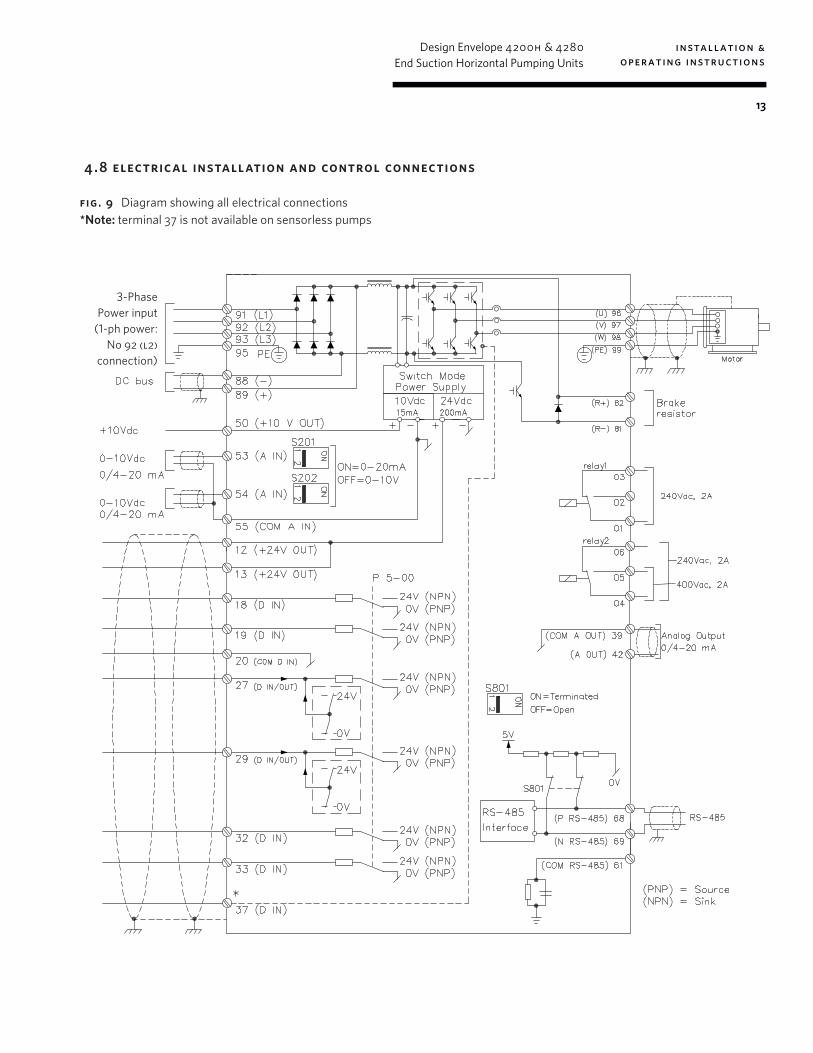
4 .8 electrical installation and control connections
fig. 9 Diagram showing all electrical connections *Note: terminal 37 is not available on sensorless pumps
Page 13 of 26
Figure 9. Diagram Showing all Electrical Connections
*Note:Terminal 37 is not available on IVS Sensorless pumps
4.8 ELECTRICAL INSTALLATION AND CONTROL CONNECTIONS
3-PhasePower input
(1-ph power: No 92 (l2)
connection)
installation & operating instructions
Design Envelope 4200h & 4280End Suction Horizontal Pumping Units
14
4 .8.1 access to terminals
Page 14 of 26
4.8.1 ACCESS TO TERMINALS
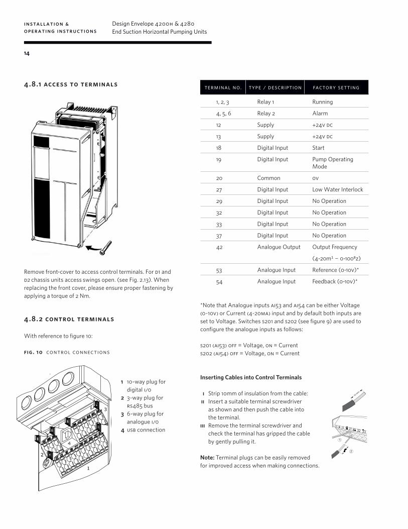
Remove front-cover to access control terminals. For D1 and D2 chassis IVS units access swings open. (see Fig. 2.13) . When replacing the front cover, please ensure proper fasten-ing by applying a torque of 2 Nm. 4.8.2 CONTROL TERMINALS
With reference to gure 10:
1. 10 way plug for digital I/O
2. 3 way plug for RS485 Bus
3. 6 way plug for analogue I/O
4. USB Connection
Control terminal functions and factory settings are as follows:
*Note that Analogue inputs AI53 and AI54 can be either Volt-age (0-10V) or Current (4-20mA) input and by default both inputs are set to Voltage. Switches S201 and S202 (see gure 9) are used to congure the analogue inputs as follows: S201 (AI53) OFF = Voltage, ON = Current S202 (AI54) OFF = Voltage, ON = Current Inserting Cables into Control Terminals i) Strip 10mm of insulation from the cable: ii) Insert a suitable terminal screwdriver as shown and then push the cable into the terminal. Iii) Remove the terminal screwdriver and check the terminal has gripped the cable by gently pulling it. Note: Terminal plugs can be easily re-moved for improved access when making connections.
Terminal No. Type / Description Factory Setting
1,2,3 Relay 1 Running
4,5,6 Relay 2 Alarm
12 Supply +24V DC
13 Supply +24V DC
18 Digital Input Start
19 Digital Input Pump Operating Mode
20 Common 0V
27 Digital Input Low Water Interlock
29 Digital Input No Operation
32 Digital Input No Operation
33 Digital Input No Operation
37 Digital Input No Operation
42 Analogue Output Output Frequency (4-20mA - 0-100Hz)
53 Analogue Input Reference (0-10V)*
54 Analogue Input Feedback (0-10V)*
Figure 10. Control Connections
Remove front-cover to access control terminals. For d1 and d2 chassis units access swings open. (see Fig. 2.13). When replacing the front cover, please ensure proper fastening by applying a torque of 2 Nm.
4 .8. 2 control terminals
With reference to figure 10:
fig . 10 control connections
terminal no. type / description factory setting
1, 2, 3 Relay 1 Running
4, 5, 6 Relay 2 Alarm
12 Supply +24v dc
13 Supply +24v dc
18 Digital Input Start
19 Digital Input Pump Operating Mode
20 Common 0v
27 Digital Input Low Water Interlock
29 Digital Input No Operation
32 Digital Input No Operation
33 Digital Input No Operation
37 Digital Input No Operation
42 Analogue Output Output Frequency
(4-20mA - 0-100Hz)
53 Analogue Input Reference (0-10v)*
54 Analogue Input Feedback (0-10v)*
*Note that Analogue inputs ai53 and ai54 can be either Voltage (0-10v) or Current (4-20ma) input and by default both inputs are set to Voltage. Switches s201 and s202 (see figure 9) are used to configure the analogue inputs as follows:
s201 (ai53) off = Voltage, on = Currents202 (ai54) off = Voltage, on = Current
Inserting Cables into Control Terminals
i Strip 10mm of insulation from the cable: ii Insert a suitable terminal screwdriver
as shown and then push the cable into the terminal.
iii Remove the terminal screwdriver and check the terminal has gripped the cable by gently pulling it.
Note: Terminal plugs can be easily removed for improved access when making connections.
Page 14 of 26
4.8.1 ACCESS TO TERMINALS
Remove front-cover to access control terminals. For D1 and D2 chassis IVS units access swings open. (see Fig. 2.13) . When replacing the front cover, please ensure proper fasten-ing by applying a torque of 2 Nm. 4.8.2 CONTROL TERMINALS
With reference to gure 10:
1. 10 way plug for digital I/O
2. 3 way plug for RS485 Bus
3. 6 way plug for analogue I/O
4. USB Connection
Control terminal functions and factory settings are as follows:
*Note that Analogue inputs AI53 and AI54 can be either Volt-age (0-10V) or Current (4-20mA) input and by default both inputs are set to Voltage. Switches S201 and S202 (see gure 9) are used to congure the analogue inputs as follows: S201 (AI53) OFF = Voltage, ON = Current S202 (AI54) OFF = Voltage, ON = Current Inserting Cables into Control Terminals i) Strip 10mm of insulation from the cable: ii) Insert a suitable terminal screwdriver as shown and then push the cable into the terminal. Iii) Remove the terminal screwdriver and check the terminal has gripped the cable by gently pulling it. Note: Terminal plugs can be easily re-moved for improved access when making connections.
Terminal No. Type / Description Factory Setting
1,2,3 Relay 1 Running
4,5,6 Relay 2 Alarm
12 Supply +24V DC
13 Supply +24V DC
18 Digital Input Start
19 Digital Input Pump Operating Mode
20 Common 0V
27 Digital Input Low Water Interlock
29 Digital Input No Operation
32 Digital Input No Operation
33 Digital Input No Operation
37 Digital Input No Operation
42 Analogue Output Output Frequency (4-20mA - 0-100Hz)
53 Analogue Input Reference (0-10V)*
54 Analogue Input Feedback (0-10V)*
Figure 10. Control Connections
1 10-way plug for digital i/0
2 3-way plug for rs485 bus
3 6-way plug for analogue i/0
4 usb connection
Page 14 of 26
4.8.1 ACCESS TO TERMINALS
Remove front-cover to access control terminals. For D1 and D2 chassis IVS units access swings open. (see Fig. 2.13) . When replacing the front cover, please ensure proper fasten-ing by applying a torque of 2 Nm. 4.8.2 CONTROL TERMINALS
With reference to gure 10:
1. 10 way plug for digital I/O
2. 3 way plug for RS485 Bus
3. 6 way plug for analogue I/O
4. USB Connection
Control terminal functions and factory settings are as follows:
*Note that Analogue inputs AI53 and AI54 can be either Volt-age (0-10V) or Current (4-20mA) input and by default both inputs are set to Voltage. Switches S201 and S202 (see gure 9) are used to congure the analogue inputs as follows: S201 (AI53) OFF = Voltage, ON = Current S202 (AI54) OFF = Voltage, ON = Current Inserting Cables into Control Terminals i) Strip 10mm of insulation from the cable: ii) Insert a suitable terminal screwdriver as shown and then push the cable into the terminal. Iii) Remove the terminal screwdriver and check the terminal has gripped the cable by gently pulling it. Note: Terminal plugs can be easily re-moved for improved access when making connections.
Terminal No. Type / Description Factory Setting
1,2,3 Relay 1 Running
4,5,6 Relay 2 Alarm
12 Supply +24V DC
13 Supply +24V DC
18 Digital Input Start
19 Digital Input Pump Operating Mode
20 Common 0V
27 Digital Input Low Water Interlock
29 Digital Input No Operation
32 Digital Input No Operation
33 Digital Input No Operation
37 Digital Input No Operation
42 Analogue Output Output Frequency (4-20mA - 0-100Hz)
53 Analogue Input Reference (0-10V)*
54 Analogue Input Feedback (0-10V)*
Figure 10. Control Connections

installation & operating instructions
Design Envelope 4200h & 4280End Suction Horizontal Pumping Units
15
4 .8.3 connection examples
Sensorless pumps can be configured in four main ways:
i Sensorless ii Closed loop – with feedback sensor iii Constant Curve Mode – Potentiometer Control iv Constant Curve Mode – bms signal iv.i) Full Speed Override
i sensorless
sensorless pumps are factory configured to be connected as shown below.
Page 15 of 26
ii. CLOSED LOOP - WITH SENSOR FEEDBACK.To control the pump based on a 0-10v feedback signal from a sensor use the following connection.
iii. CONSTANT CURVE MODE - POTENTIOMETER
CONTROL To control the pump based on a 0-10v potentiometer sig-
nal use the connections below.
4.8.3 CONNECTION EXAMPLES
IVS Sensorless pumps can be congured in 4 main ways: i. Sensorless ii. Closed Loop – with feedback sensor iii. Constant Curve Mode – Potentiometer Control iv. Constant Curve Mode – BMS signal iv.i) Full Speed Override
i. SENSORLESS IVS Sensorless pumps are factor y congured to be connected as shown below.
12 (+24v)
20 (0v)
18 (D IN) Start Signal
Output Frequency 4-20mA Analogue Out
Running Output
Alarm Output
19 (D IN)
29 (D IN)
32 (D IN)
33 (D IN)
50 (10V)
53 (Ain)
54 (Ain)
55 (0 v)
42 (Aout)
39 (Aout)
2 (R1 N/O)
3 (R1 N/C)
1 (R1 COM)
5 (R2 N/O)
6 (R2 N/C)
4 (R2 COM)
24V
12 (+24v)
20 (0v)
18 (D IN) Start Signal
Output Frequency 4-20mA Analogue Out
Running Output
Alarm Output
19 (D IN)
27 (D IN)
29 (D IN)
32 (D IN)
33 (D IN)
50 (10V)
53 (Ain)
54 (Ain)
55 (0 v)
42 (Aout)
39 (Aout)
2 (R1 N/O)
3 (R1 N/C)
1 (R1 COM)
5 (R2 N/O)
6 (R2 N/C)
4 (R2 COM)
Pressure Sensor (0-10 Bar / 4-20mA)
Feedback from Sensor 4-20mA—Input T54 Power Supply (24 Vdc) for sensor T13=24V
ii closed loop – with sensor feedback
To control the pump based on a 4-20ma feedback signal from a sensor use the following connection.
Page 15 of 26
ii. CLOSED LOOP - WITH SENSOR FEEDBACK.To control the pump based on a 0-10v feedback signal from a sensor use the following connection.
iii. CONSTANT CURVE MODE - POTENTIOMETER
CONTROL To control the pump based on a 0-10v potentiometer sig-
nal use the connections below.
4.8.3 CONNECTION EXAMPLES
IVS Sensorless pumps can be congured in 4 main ways: i. Sensorless ii. Closed Loop – with feedback sensor iii. Constant Curve Mode – Potentiometer Control iv. Constant Curve Mode – BMS signal iv.i) Full Speed Override
i. SENSORLESS IVS Sensorless pumps are factor y congured to be connected as shown below.
12 (+24v)
20 (0v)
18 (D IN) Start Signal
Output Frequency 4-20mA Analogue Out
Running Output
Alarm Output
19 (D IN)
29 (D IN)
32 (D IN)
33 (D IN)
50 (10V)
53 (Ain)
54 (Ain)
55 (0 v)
42 (Aout)
39 (Aout)
2 (R1 N/O)
3 (R1 N/C)
1 (R1 COM)
5 (R2 N/O)
6 (R2 N/C)
4 (R2 COM)
24V
12 (+24v)
20 (0v)
18 (D IN) Start Signal
Output Frequency 4-20mA Analogue Out
Running Output
Alarm Output
19 (D IN)
27 (D IN)
29 (D IN)
32 (D IN)
33 (D IN)
50 (10V)
53 (Ain)
54 (Ain)
55 (0 v)
42 (Aout)
39 (Aout)
2 (R1 N/O)
3 (R1 N/C)
1 (R1 COM)
5 (R2 N/O)
6 (R2 N/C)
4 (R2 COM)
Pressure Sensor (0-10 Bar / 4-20mA)
Feedback from Sensor 4-20mA—Input T54 Power Supply (24 Vdc) for sensor T13=24V

installation & operating instructions
Design Envelope 4200h & 4280End Suction Horizontal Pumping Units
16
iii constant curve mode – potentiometer
To control the pump based on a 0-10v potentiometer signal use the connections below.
Page 16 of 26
iv. CONSTANT CURVE MODE - BMS SIGNALWhen the Building Management System is to be used for speed control it is necessary to disable sensorless control and provide the unit with a 0-10VDC speed reference signal.
12 (+24v)
20 (0v)
18 (D IN) Start Signal
Output Frequency 4-20mA Analogue
Running Output
Alarm Output
19 (D IN)
27 (D IN)
29 (D IN)
32 (D IN)
33 (D IN)
50 (10V)
53 (Ain)
54 (Ain)
55 (0 v)
42 (Aout)
39 (Aout)
2 (R1 N/O)
3 (R1 N/C)
1 (R1 COM)
5 (R2 N/O)
6 (R2 N/C)
4 (R2 COM)
0-10V Derived from 1k Potentiometer into
Input T53 (common
12 (+24v)
20 (0v)
18 (D IN) Start Signal
Output Frequency 4-20mA Analogue
Running Output
Alarm Output
19 (D IN)
27 (D IN)
29 (D IN)
32 (D IN)
33 (D IN)
50 (10V)
53 (Ain)
54 (Ain)
55 (0 v)
42 (Aout)
39 (Aout)
2 (R1 N/O)
3 (R1 N/C)
1 (R1 COM)
5 (R2 N/O)
6 (R2 N/C)
4 (R2 COM)
0-10v Signal from BMS Input T53 (common
T55)
iv.i CONSTANT CURVE MODE - BMS SIGNALIt may be required to run the pump at full speed without automatic speed control (eg during system commissioning). This can be achieved without programming changes by making the connections below.
4.8.4 REMOTE LCP KEYPAD WIRING
For large IVS units with remote LCP keypad, see wiring arrangement below
LCP Wiring Arrangement
12 (+24v)
20 (0v)
18 (D IN) Start Signal
Output Frequency 4-20mA Analogue Out
Running Output
Alarm Output
19 (D IN)
27 (D IN)
29 (D IN)
32 (D IN)
33 (D IN)
50 (10V)
53 (Ain)
54 (Ain)
55 (0 v)
42 (Aout)
39 (Aout)
2 (R1 N/O)
3 (R1 N/C)
1 (R1 COM)
5 (R2 N/O)
6 (R2 N/C)
4 (R2 COM)
Link 10Vdc (T50 ) into Analogue Input T53
Terminal Wire Color
1 Green
2 Brown
3 Red
4 Yellow
5 Black
6 Orange
7 Blue
8 Purple
9 Grey
iv constant curve mode – bms signal
When the Building Management System is to be used for speed control it is necessary to disable sensorless control and provide the unit with a 0-10vdc speed reference signal.
Page 16 of 26
iv. CONSTANT CURVE MODE - BMS SIGNALWhen the Building Management System is to be used for speed control it is necessary to disable sensorless control and provide the unit with a 0-10VDC speed reference signal.
12 (+24v)
20 (0v)
18 (D IN) Start Signal
Output Frequency 4-20mA Analogue
Running Output
Alarm Output
19 (D IN)
27 (D IN)
29 (D IN)
32 (D IN)
33 (D IN)
50 (10V)
53 (Ain)
54 (Ain)
55 (0 v)
42 (Aout)
39 (Aout)
2 (R1 N/O)
3 (R1 N/C)
1 (R1 COM)
5 (R2 N/O)
6 (R2 N/C)
4 (R2 COM)
0-10V Derived from 1k Potentiometer into
Input T53 (common
12 (+24v)
20 (0v)
18 (D IN) Start Signal
Output Frequency 4-20mA Analogue
Running Output
Alarm Output
19 (D IN)
27 (D IN)
29 (D IN)
32 (D IN)
33 (D IN)
50 (10V)
53 (Ain)
54 (Ain)
55 (0 v)
42 (Aout)
39 (Aout)
2 (R1 N/O)
3 (R1 N/C)
1 (R1 COM)
5 (R2 N/O)
6 (R2 N/C)
4 (R2 COM)
0-10v Signal from BMS Input T53 (common
T55)
iv.i CONSTANT CURVE MODE - BMS SIGNALIt may be required to run the pump at full speed without automatic speed control (eg during system commissioning). This can be achieved without programming changes by making the connections below.
4.8.4 REMOTE LCP KEYPAD WIRING
For large IVS units with remote LCP keypad, see wiring arrangement below
LCP Wiring Arrangement
12 (+24v)
20 (0v)
18 (D IN) Start Signal
Output Frequency 4-20mA Analogue Out
Running Output
Alarm Output
19 (D IN)
27 (D IN)
29 (D IN)
32 (D IN)
33 (D IN)
50 (10V)
53 (Ain)
54 (Ain)
55 (0 v)
42 (Aout)
39 (Aout)
2 (R1 N/O)
3 (R1 N/C)
1 (R1 COM)
5 (R2 N/O)
6 (R2 N/C)
4 (R2 COM)
Link 10Vdc (T50 ) into Analogue Input T53
Terminal Wire Color
1 Green
2 Brown
3 Red
4 Yellow
5 Black
6 Orange
7 Blue
8 Purple
9 Grey
iv.i constant curve mode - bms signal
It may be required to run the pump at full speed without automatic speed control (eg during system commissioning). This can be achieved without programming changes by making the connec-tions below.
Page 16 of 26
iv. CONSTANT CURVE MODE - BMS SIGNALWhen the Building Management System is to be used for speed control it is necessary to disable sensorless control and provide the unit with a 0-10VDC speed reference signal.
12 (+24v)
20 (0v)
18 (D IN) Start Signal
Output Frequency 4-20mA Analogue
Running Output
Alarm Output
19 (D IN)
27 (D IN)
29 (D IN)
32 (D IN)
33 (D IN)
50 (10V)
53 (Ain)
54 (Ain)
55 (0 v)
42 (Aout)
39 (Aout)
2 (R1 N/O)
3 (R1 N/C)
1 (R1 COM)
5 (R2 N/O)
6 (R2 N/C)
4 (R2 COM)
0-10V Derived from 1k Potentiometer into
Input T53 (common
12 (+24v)
20 (0v)
18 (D IN) Start Signal
Output Frequency 4-20mA Analogue
Running Output
Alarm Output
19 (D IN)
27 (D IN)
29 (D IN)
32 (D IN)
33 (D IN)
50 (10V)
53 (Ain)
54 (Ain)
55 (0 v)
42 (Aout)
39 (Aout)
2 (R1 N/O)
3 (R1 N/C)
1 (R1 COM)
5 (R2 N/O)
6 (R2 N/C)
4 (R2 COM)
0-10v Signal from BMS Input T53 (common
T55)
iv.i CONSTANT CURVE MODE - BMS SIGNALIt may be required to run the pump at full speed without automatic speed control (eg during system commissioning). This can be achieved without programming changes by making the connections below.
4.8.4 REMOTE LCP KEYPAD WIRING
For large IVS units with remote LCP keypad, see wiring arrangement below
LCP Wiring Arrangement
12 (+24v)
20 (0v)
18 (D IN) Start Signal
Output Frequency 4-20mA Analogue Out
Running Output
Alarm Output
19 (D IN)
27 (D IN)
29 (D IN)
32 (D IN)
33 (D IN)
50 (10V)
53 (Ain)
54 (Ain)
55 (0 v)
42 (Aout)
39 (Aout)
2 (R1 N/O)
3 (R1 N/C)
1 (R1 COM)
5 (R2 N/O)
6 (R2 N/C)
4 (R2 COM)
Link 10Vdc (T50 ) into Analogue Input T53
Terminal Wire Color
1 Green
2 Brown
3 Red
4 Yellow
5 Black
6 Orange
7 Blue
8 Purple
9 Grey
installation & operating instructions
Design Envelope 4200h & 4280End Suction Horizontal Pumping Units
17
5 programming, monitoring and diagnotics
pumps incorporate an integrated graphical local control panel (glcp).
5 .1 glcp functions and operation
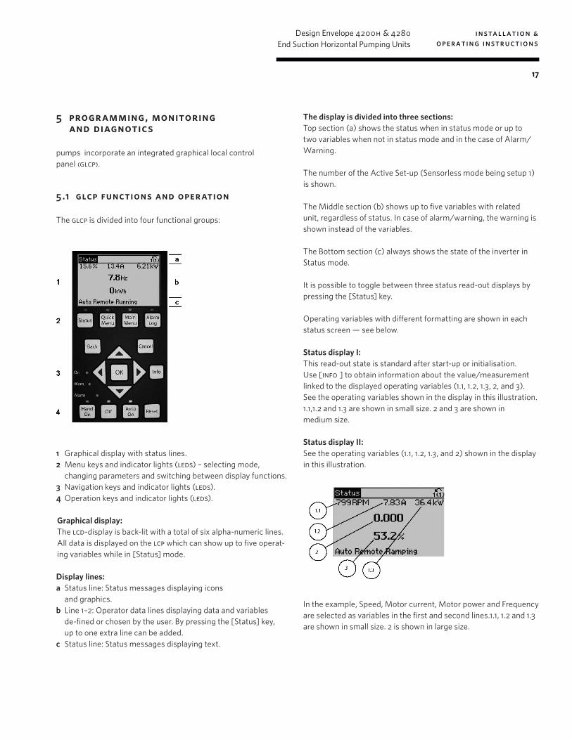
The glcp is divided into four functional groups:
1 Graphical display with status lines.2 Menu keys and indicator lights (leds) – selecting mode,
changing parameters and switching between display functions.3 Navigation keys and indicator lights (leds).4 Operation keys and indicator lights (leds).
Graphical display: The lcd-display is back-lit with a total of six alpha-numeric lines. All data is displayed on the lcp which can show up to five operat-ing variables while in [Status] mode.
Display lines:a Status line: Status messages displaying icons
and graphics.b Line 1–2: Operator data lines displaying data and variables
de-fined or chosen by the user. By pressing the [Status] key, up to one extra line can be added.
c Status line: Status messages displaying text.
The display is divided into three sections:Top section (a) shows the status when in status mode or up to two variables when not in status mode and in the case of Alarm/Warning.
The number of the Active Set-up (Sensorless mode being setup 1) is shown.
The Middle section (b) shows up to five variables with related unit, regardless of status. In case of alarm/warning, the warning is shown instead of the variables.
The Bottom section (c) always shows the state of the inverter in Status mode.
It is possible to toggle between three status read-out displays by pressing the [Status] key.
Operating variables with different formatting are shown in each status screen — see below.
Status display I:This read-out state is standard after start-up or initialisation.Use [info ] to obtain information about the value/measurement linked to the displayed operating variables (1.1, 1.2, 1.3, 2, and 3). See the operating variables shown in the display in this illustration. 1.1,1.2 and 1.3 are shown in small size. 2 and 3 are shown in medium size.
Status display II:See the operating variables (1.1, 1.2, 1.3, and 2) shown in the display in this illustration.
In the example, Speed, Motor current, Motor power and Frequency are selected as variables in the first and second lines.1.1, 1.2 and 1.3 are shown in small size. 2 is shown in large size.
installation & operating instructions
Design Envelope 4200h & 4280End Suction Horizontal Pumping Units
18
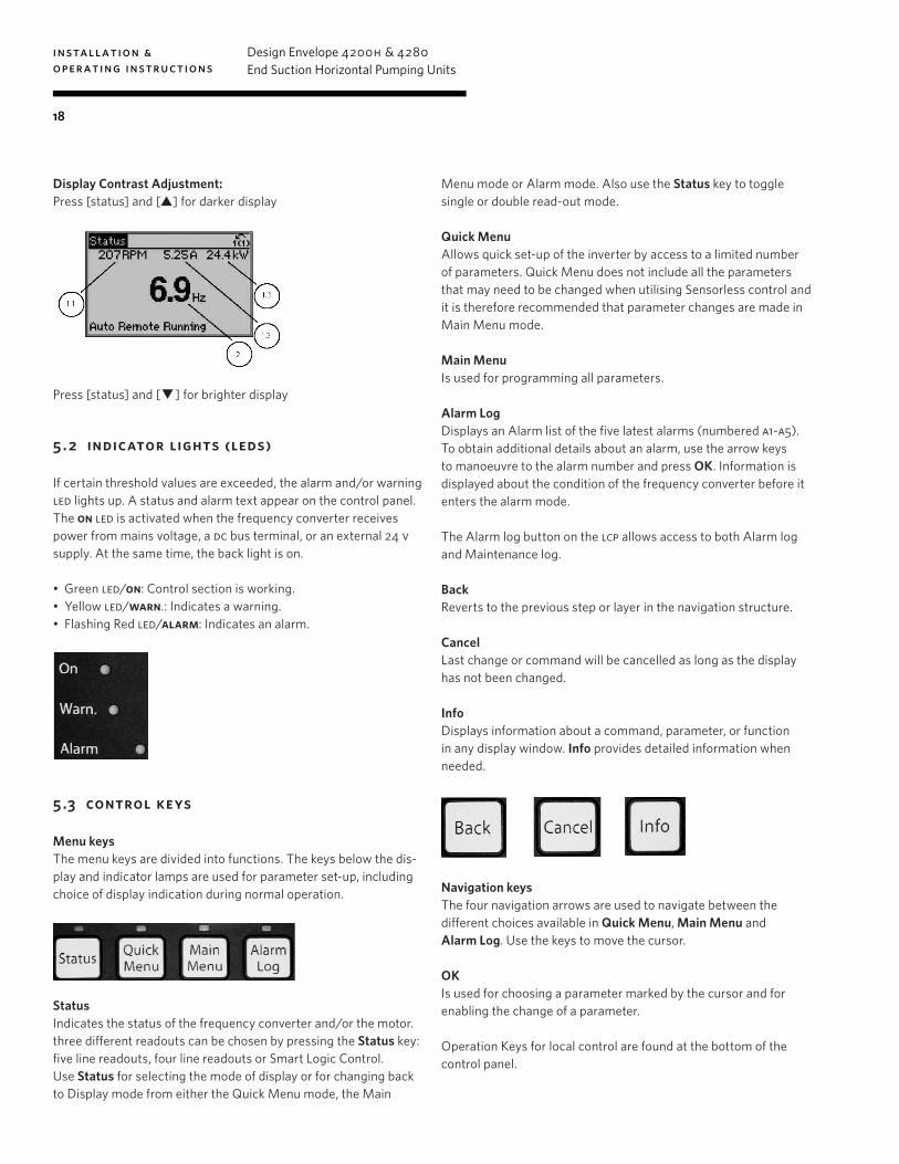
Display Contrast Adjustment:Press [status] and [] for darker display
Press [status] and [] for brighter display
5 . 2 indicator lights (leds)
If certain threshold values are exceeded, the alarm and/or warning led lights up. A status and alarm text appear on the control panel.The on led is activated when the frequency converter receives power from mains voltage, a dc bus terminal, or an external 24 v supply. At the same time, the back light is on.
• Green led/on: Control section is working.• Yellow led/warn.: Indicates a warning.• Flashing Red led/alarm: Indicates an alarm.
5 .3 control keys
Menu keysThe menu keys are divided into functions. The keys below the dis-play and indicator lamps are used for parameter set-up, including choice of display indication during normal operation.
StatusIndicates the status of the frequency converter and/or the motor. three different readouts can be chosen by pressing the Status key: five line readouts, four line readouts or Smart Logic Control.Use Status for selecting the mode of display or for changing back to Display mode from either the Quick Menu mode, the Main
Menu mode or Alarm mode. Also use the Status key to toggle single or double read-out mode.
Quick MenuAllows quick set-up of the inverter by access to a limited number of parameters. Quick Menu does not include all the parameters that may need to be changed when utilising Sensorless control and it is therefore recommended that parameter changes are made in Main Menu mode.
Main MenuIs used for programming all parameters.
Alarm LogDisplays an Alarm list of the five latest alarms (numbered a1-a5). To obtain additional details about an alarm, use the arrow keys to manoeuvre to the alarm number and press OK. Information is displayed about the condition of the frequency converter before it enters the alarm mode.
The Alarm log button on the lcp allows access to both Alarm log and Maintenance log.
BackReverts to the previous step or layer in the navigation structure.
CancelLast change or command will be cancelled as long as the display has not been changed.
InfoDisplays information about a command, parameter, or function in any display window. Info provides detailed information when needed.
Navigation keysThe four navigation arrows are used to navigate between the different choices available in Quick Menu, Main Menu and Alarm Log. Use the keys to move the cursor.
OKIs used for choosing a parameter marked by the cursor and for enabling the change of a parameter.
Operation Keys for local control are found at the bottom of the control panel.

installation & operating instructions
Design Envelope 4200h & 4280End Suction Horizontal Pumping Units
19
Hand On. Enables control of the pump via the glcp. It is possible to enter the pump speed data by means of the arrow keys.
The low water device input must be made for the pump to start in either hand mode or auto mode.
OffStops the pump.
Auto OnEnables the pump to be controlled via the control terminals and/or serial communication. When a start signal is applied on the control terminals the pump will start.
For the pump to operate in either Sensorless mode or any other automatic control mode it is necessary to have pressed the [Auto on] button.
ResetIs used for resetting the frequency converter after an alarm (trip).
5 . 4 programming
Select the Main Menu mode by pressing the [Main Menu] key. The below read-out appears on the display. The middle and bottom sections on the display show a list of parameter groups which can be chosen by toggling the up and down buttons.
Each parameter has a name and number which remain the same regardless of the programming mode. In the Main Menu mode, the parameters are divided into groups. The first digit of the parameter number (from the left) indicates the parameter group number.
All parameters can be changed in the Main Menu. However, depending on the choice of configuration (par. 1-00 Configuration Mode), some parameters can be hidden.
5 . 4 .1 parameter selection
In the Main Menu mode, the parameters are divided into groups. You select a parameter group by means of the navigation keys.
The following parameter groups are accessible:
group no.
parameter group
group no.
parameter group
0 Operation/display 13 Smart Logic
1 Load/motor 14 Special functions
2 Brakes 15 fc information
3 References/ramps 16 Data readouts
4 Limits/warnings 18 Data readouts 2
5 Digital in/out 20 Drive closed loop
6 Analog in/out 21 Ext. closed loop
8 Com. and options 22 Application functions
9 Profibus 23 Time-based functions
10 can Fieldbus 25 Cascade controller
11 LonWorks 26 Analog i/0 option mcb 109
After selecting a parameter group, choose a parameter by means of the navigation keys.
The middle section on the display shows the parameter number and name as well as the selected parameter value.
installation & operating instructions
Design Envelope 4200h & 4280End Suction Horizontal Pumping Units
20
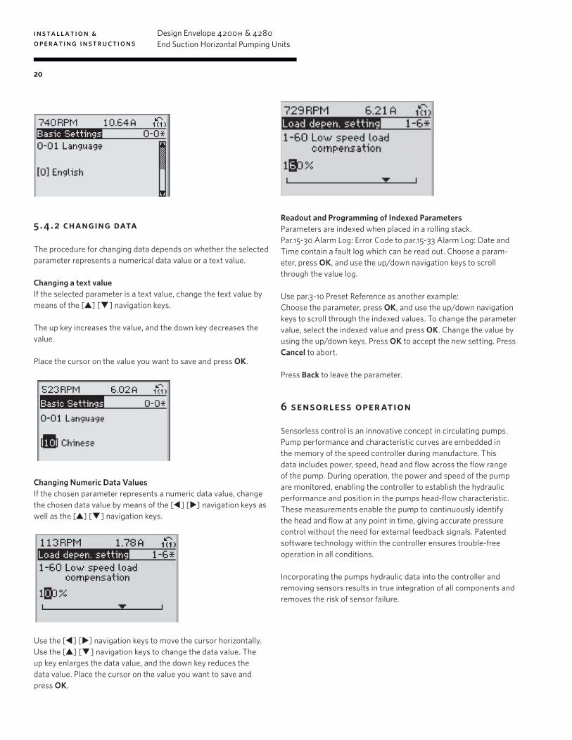
5 . 4 . 2 changing data
The procedure for changing data depends on whether the selected parameter represents a numerical data value or a text value.
Changing a text valueIf the selected parameter is a text value, change the text value by means of the [] [] navigation keys.
The up key increases the value, and the down key decreases the value.
Place the cursor on the value you want to save and press OK.
Changing Numeric Data ValuesIf the chosen parameter represents a numeric data value, change the chosen data value by means of the [] [] navigation keys as well as the [] [] navigation keys.
Use the [] [] navigation keys to move the cursor horizontally.Use the [] [] navigation keys to change the data value. The up key enlarges the data value, and the down key reduces the data value. Place the cursor on the value you want to save and press OK.
Readout and Programming of Indexed ParametersParameters are indexed when placed in a rolling stack.Par.15-30 Alarm Log: Error Code to par.15-33 Alarm Log: Date and Time contain a fault log which can be read out. Choose a param-eter, press OK, and use the up/down navigation keys to scroll through the value log.
Use par.3-10 Preset Reference as another example:Choose the parameter, press OK, and use the up/down navigation keys to scroll through the indexed values. To change the parameter value, select the indexed value and press OK. Change the value by using the up/down keys. Press OK to accept the new setting. Press Cancel to abort.
Press Back to leave the parameter.
6 sensorless operation
Sensorless control is an innovative concept in circulating pumps. Pump performance and characteristic curves are embedded in the memory of the speed controller during manufacture. This data includes power, speed, head and flow across the flow range of the pump. During operation, the power and speed of the pump are monitored, enabling the controller to establish the hydraulic performance and position in the pumps head-flow characteristic.These measurements enable the pump to continuously identify the head and flow at any point in time, giving accurate pressure control without the need for external feedback signals. Patented software technology within the controller ensures trouble-free operation in all conditions.
Incorporating the pumps hydraulic data into the controller and removing sensors results in true integration of all components and removes the risk of sensor failure.
installation & operating instructions
Design Envelope 4200h & 4280End Suction Horizontal Pumping Units
21
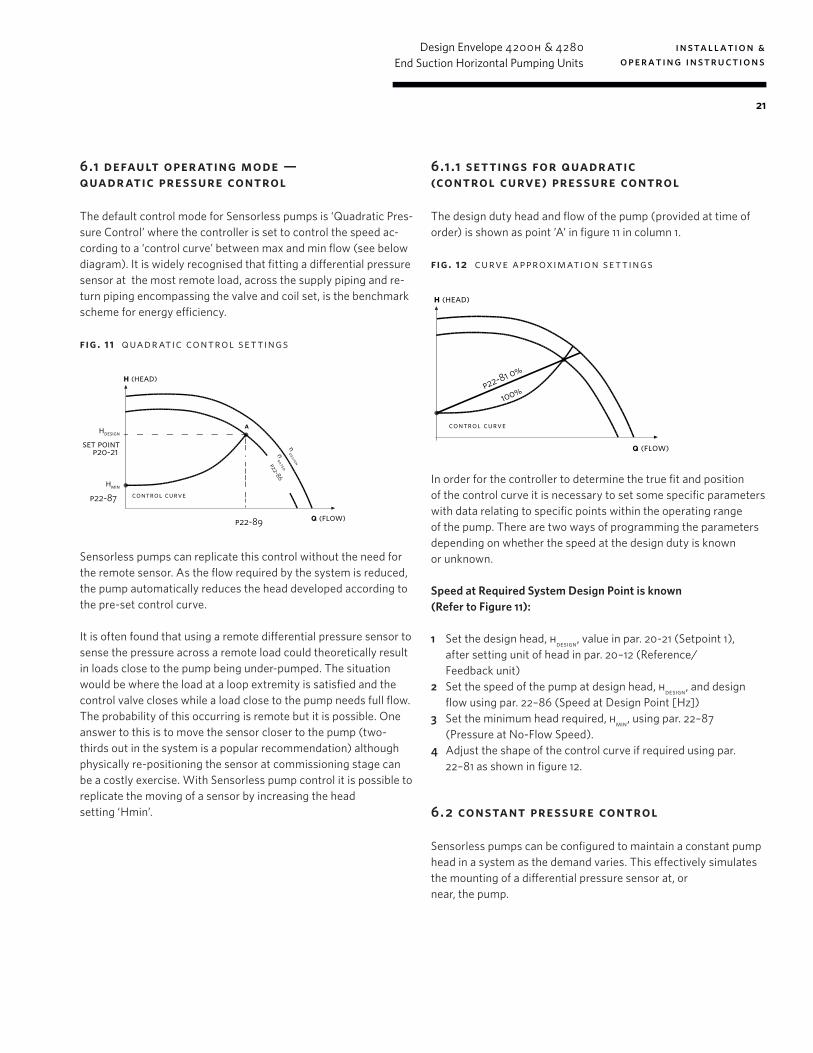
6.1 default operating mode — quadratic pressure control
The default control mode for Sensorless pumps is ‘Quadratic Pres-sure Control’ where the controller is set to control the speed ac-cording to a ‘control curve’ between max and min flow (see below diagram). It is widely recognised that fitting a differential pressure sensor at the most remote load, across the supply piping and re-turn piping encompassing the valve and coil set, is the benchmark scheme for energy efficiency.
fig . 11 quadratic control set tings
p22-86
h (head)
q (flow)
p22-87hmin
hdesign
set point
control curve
a
ndesign
nrated
p22-89
p20-21
Sensorless pumps can replicate this control without the need for the remote sensor. As the flow required by the system is reduced, the pump automatically reduces the head developed according to the pre-set control curve.
It is often found that using a remote differential pressure sensor to sense the pressure across a remote load could theoretically result in loads close to the pump being under-pumped. The situation would be where the load at a loop extremity is satisfied and the control valve closes while a load close to the pump needs full flow. The probability of this occurring is remote but it is possible. One answer to this is to move the sensor closer to the pump (two-thirds out in the system is a popular recommendation) although physically re-positioning the sensor at commissioning stage can be a costly exercise. With Sensorless pump control it is possible to replicate the moving of a sensor by increasing the head setting ‘Hmin’.
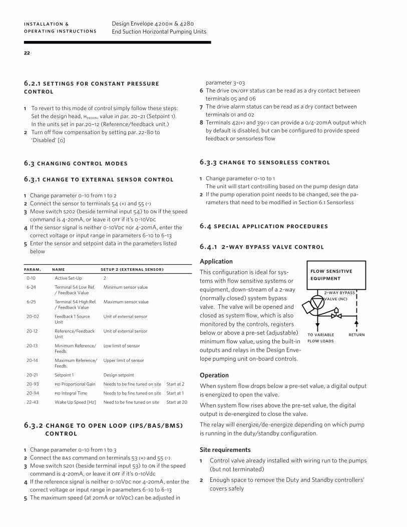
6.1.1 settings for quadratic (control curve) pressure control
The design duty head and flow of the pump (provided at time of order) is shown as point ’A’ in figure 11 in column 1.
fig . 12 curve approximation set tings
h (head)
q (flow)
p22-81 0%
100%
control curve
In order for the controller to determine the true fit and position of the control curve it is necessary to set some specific parameters with data relating to specific points within the operating range of the pump. There are two ways of programming the parameters depending on whether the speed at the design duty is known or unknown.
Speed at Required System Design Point is known (Refer to Figure 11):
1 Set the design head, hdesign, value in par. 20-21 (Setpoint 1), after setting unit of head in par. 20–12 (Reference/ Feedback unit)
2 Set the speed of the pump at design head, hdesign, and design flow using par. 22–86 (Speed at Design Point [Hz])
3 Set the minimum head required, hmin, using par. 22–87 (Pressure at No-Flow Speed).
4 Adjust the shape of the control curve if required using par. 22–81 as shown in figure 12.
6. 2 constant pressure control
Sensorless pumps can be configured to maintain a constant pump head in a system as the demand varies. This effectively simulates the mounting of a differential pressure sensor at, or near, the pump.
installation & operating instructions
Design Envelope 4200h & 4280End Suction Horizontal Pumping Units
22
6. 2.1 settings for constant pressure control
1 To revert to this mode of control simply follow these steps: Set the design head, hdesign, value in par. 20–21 (Setpoint 1).
In the units set in par.20–12 (Reference/feedback unit.)2 Turn off flow compensation by setting par. 22-80 to
‘Disabled’ [0]
6.3 changing control modes
6.3 .1 change to external sensor control
1 Change parameter 0-10 from 1 to 22 Connect the sensor to terminals 54 (+) and 55 (-)3 Move switch s202 (beside terminal input 54) to on if the speed
command is 4-20mA, or leave it off if it’s 0-10Vdc4 If the sensor signal is neither 0-10Vdc nor 4-20mA, enter the
correct voltage or input range in parameters 6-10 to 6-13 5 Enter the sensor and setpoint data in the parameters listed
below
param. name setup 2 (external sensor)
0-10 Active Set-Up 2
6-24 Terminal 54 Low Ref. / Feedback Value
Minimum sensor value
6-25 Terminal 54 High Ref./ Feedback Value
Maximum sensor value
20-02 Feedback 1 Source Unit
Unit of external sensor
20-12 Reference/Feedback Unit
Unit of external sensor
20-13 Minimum Reference/Feedb.
Low limit of sensor
20-14 Maximum Reference/Feedb.
Upper limit of sensor
20-21 Setpoint 1 Design setpoint
20-93 pid Proportional Gain Needs to be fine tuned on site Start at 2
20-94 pid Integral Time Needs to be fine tuned on site Start at 1
22-43 Wake Up Speed [Hz] Need to be fine tuned on site Start at 20
6.3.2 change to open loop (ips/bas/bms) control
1 Change parameter 0-10 from 1 to 32 Connect the bas command on terminals 53 (+) and 55 (-)3 Move switch s201 (beside terminal input 53) to on if the speed
command is 4-20mA, or leave it off if it’s 0-10Vdc4 If the reference signal is neither 0-10Vdc nor 4-20mA, enter the
correct voltage or input range in parameters 6-10 to 6-135 The maximum speed (at 20mA or 10Vdc) can be adjusted in
parameter 3-036 The drive on/off status can be read as a dry contact between
terminals 05 and 067 The drive alarm status can be read as a dry contact between
terminals 01 and 028 Terminals 42(+) and 39(-) can provide a 0/4-20mA output which
by default is disabled, but can be configured to provide speed feedback or sensorless flow
6.3 .3 change to sensorless control
1 Change parameter 0-10 to 1 The unit will start controlling based on the pump design data 2 If the pump operation point needs to be changed, see the pa-
rameters that need to be modified in Section 6.1 Sensorless
6. 4 special application procedures
6. 4 .1 2-way bypass valve control
ApplicationThis configuration is ideal for sys-tems with flow sensitive systems or equipment, down-stream of a 2-way (normally closed) system bypass valve. The valve will be opened and closed as system flow, which is also monitored by the controls, registers below or above a pre-set (adjustable) minimum flow value, using the built-in outputs and relays in the Design Enve-lope pumping unit on-board controls.
OperationWhen system flow drops below a pre-set value, a digital output is energized to open the valve.
When system flow rises above the pre-set value, the digital output is de-energized to close the valve.
The relay will energize/de-energize depending on which pump is running in the duty/standby configuration.
Site requirements1 Control valve already installed with wiring run to the pumps
(but not terminated)
2 Enough space to remove the Duty and Standby controllers’ covers safely
flow sensitiveequipment
2-way bypassvalve (nc)
to variable flow loads
return
installation & operating instructions
Design Envelope 4200h & 4280End Suction Horizontal Pumping Units
23
Personnel requirements1 Armstrong Tier 3 training or equivalent
2 Ability to terminate simple control wiring
3 Ability to configure Armstrong controls
4 All work will be done on low voltage, however, when remov-ing the controller cover high voltage may be exposed. An electrician license is required in some areas
5 Torx screw driver set
WiringIf Duty/Standby configuration, then the contact wires have to be wired to the Master controller. If it’s unknown which control-ler is the Master controller, verify the settings of parameters 13-00 to 13-02.
The Master controller is the unit that has the following param-eters configured as follows:
parameter name value13-00 slc Controller mode [1] On
13-01 Start event [37] Digital input di32
13-02 Stop event [26] Logic rule 0
2 Way control valve wiring1 Connect the Positive terminal of the control valve to the
Master controller Relay 2 [Terminal 4].
2 Connect the Commmon terminal of the control valve to the com of the Master And Slave controller (If Applicable) [Terminal 20].
3 Connect Relay 2 [Terminal 6] on the Master controller to Digital Out [Terminal 27] on the Slave controller (If Applicable).
4 Connect Digital Out [Terminal 27] on the Master controller to Relay 2 [Terminal 5] on the Master controller.
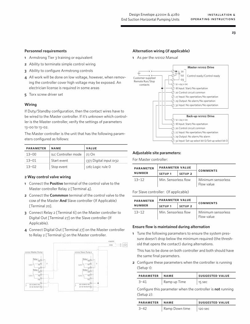
Alternation wiring (if applicable)1 As per the ivs102 Manual
Adjustable site parameters:For Master controller:
parameter number
parameter value comments
setup 1 setup 2
13-12 Min. Sensorless flow Minimum sensorless Flow value
For Slave controller: (If applicable)
parameter number
parameter value comments
setup 1 setup 2
13-12 Min. Sensorless flow Minimum sensorless Flow value
Ensure flow is maintained during alternation1 Tune the following parameters to ensure the system pres-
sure doesn’t drop below the minimum required (the thresh-old that opens the contact) during alternations.
This has to be done on both controller and both should have the same final parameters.
2 Configure these parameters when the controller is running (Setup 1):
parameter name suggested value3-41 Ramp up Time 15 sec
Configure this parameter when the controller is not running (Setup 2):
parameter name suggested value3-42 Ramp Down time 120 sec
ivs102 Master, Pump 1
Relay 1
Relay 2
03
02 2
06
05
04
20 (com d in)27 (d in/out)
01
ivs102 Slave, Pump 2
Relay 1
Relay 2
03
02 2
06
05
04
20 (com d in)27 (d in/out)
01
+24vdc
com
030201
Master ivs102 Drive
Customer-suppliedRemote Run/Stop
contacts
Back-up ivs102 Drive
Control ready/Control ready
12 +24 v dc18 Input: Start/No opertation20 Control circuit common27 Input: No opertation/No opertation29 Output: No alarm/No opertation32 Input: No opertation/No opertation
12 +24 v dc18 Input: Start/No opertation20 Control circuit common27 Input: No opertation/No opertation29 Output: No alarm/No alarm32 Input: Set-up select bit 0/Set-up select bit 0
installation & operating instructions
Design Envelope 4200h & 4280End Suction Horizontal Pumping Units
24
Testing1 Place both controllers in Auto Mode.2 Reduce the flow to the running pump until it reaches below
the value in p13-12.3 Verify the control valve starts to open.4 Increase the flow to the running pump until it reaches above
the value in p13-12.5 Verify the valve starts to close.
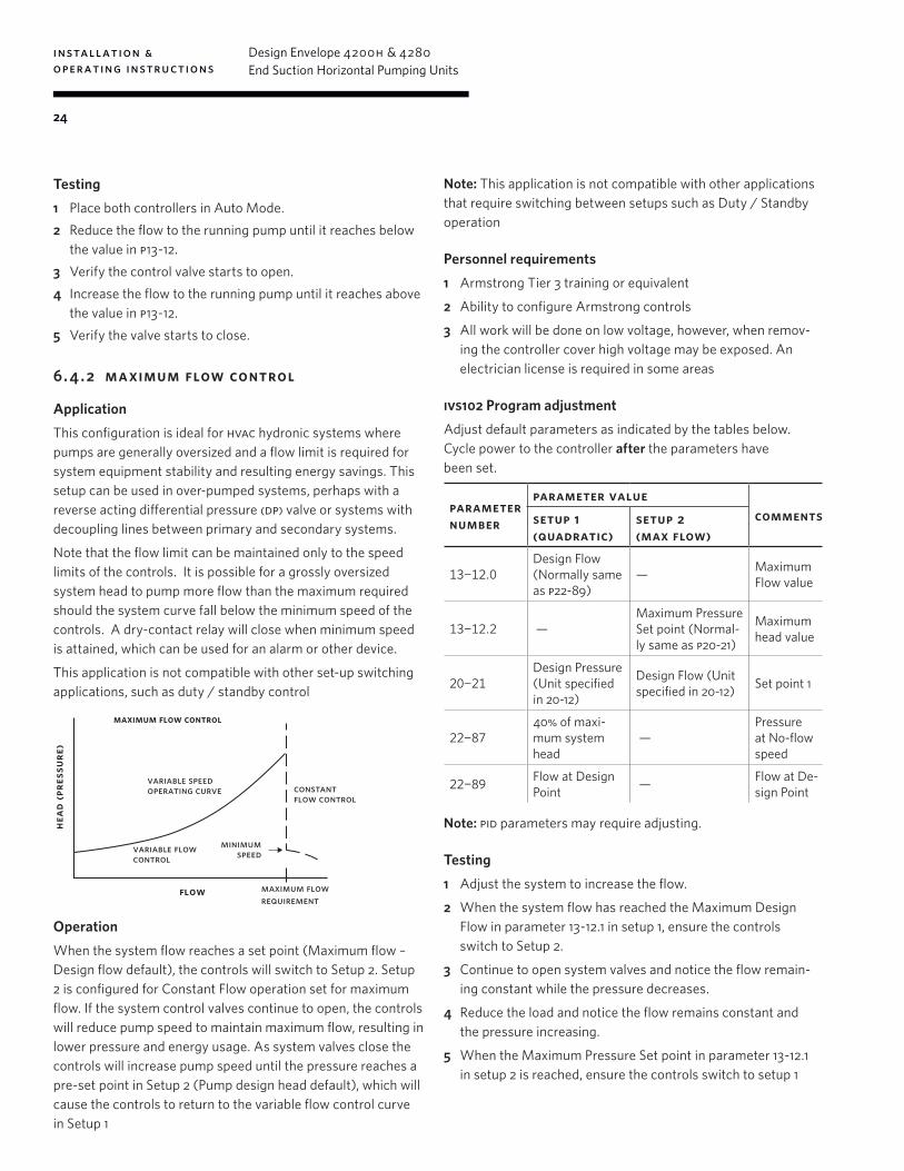
6. 4 . 2 maximum flow control
ApplicationThis configuration is ideal for hvac hydronic systems where pumps are generally oversized and a flow limit is required for system equipment stability and resulting energy savings. This setup can be used in over-pumped systems, perhaps with a reverse acting differential pressure (dp) valve or systems with decoupling lines between primary and secondary systems.
Note that the flow limit can be maintained only to the speed limits of the controls. It is possible for a grossly oversized system head to pump more flow than the maximum required should the system curve fall below the minimum speed of the controls. A dry-contact relay will close when minimum speed is attained, which can be used for an alarm or other device.
This application is not compatible with other set-up switching applications, such as duty / standby control
flow
variable speedoperating curve constant
flow control
maximum flow control
minimum speedvariable flow
control
maximum flowrequirement
head
(pre
ssur
e)
OperationWhen the system flow reaches a set point (Maximum flow – Design flow default), the controls will switch to Setup 2. Setup 2 is configured for Constant Flow operation set for maximum flow. If the system control valves continue to open, the controls will reduce pump speed to maintain maximum flow, resulting in lower pressure and energy usage. As system valves close the controls will increase pump speed until the pressure reaches a pre-set point in Setup 2 (Pump design head default), which will cause the controls to return to the variable flow control curve in Setup 1
Note: This application is not compatible with other applications that require switching between setups such as Duty / Standby operation
Personnel requirements1 Armstrong Tier 3 training or equivalent
2 Ability to configure Armstrong controls
3 All work will be done on low voltage, however, when remov-ing the controller cover high voltage may be exposed. An electrician license is required in some areas
ivs102 Program adjustmentAdjust default parameters as indicated by the tables below. Cycle power to the controller after the parameters have been set.
parameter number
parameter value comments setup 1
(quadratic) setup 2 (max flow)
13-12.0Design Flow (Normally same as p22-89)
— Maximum Flow value
13-12.2 —Maximum Pressure Set point (Normal-ly same as p20-21)
Maximum head value
20-21Design Pressure (Unit specified in 20-12)
Design Flow (Unit specified in 20-12) Set point 1
22-8740% of maxi-mum system head
—Pressure at No-flow speed
22-89Flow at Design Point — Flow at De-
sign Point
Note: pid parameters may require adjusting.
Testing1 Adjust the system to increase the flow.
2 When the system flow has reached the Maximum Design Flow in parameter 13-12.1 in setup 1, ensure the controls switch to Setup 2.
3 Continue to open system valves and notice the flow remain-ing constant while the pressure decreases.
4 Reduce the load and notice the flow remains constant and the pressure increasing.
5 When the Maximum Pressure Set point in parameter 13-12.1 in setup 2 is reached, ensure the controls switch to setup 1
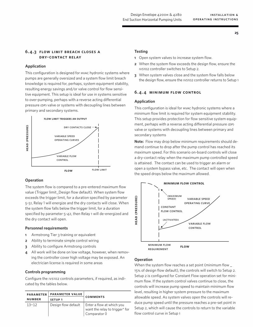
installation & operating instructions
Design Envelope 4200h & 4280End Suction Horizontal Pumping Units
25
6. 4 .3 flow limit breach closes a dry-contact relay
ApplicationThis configuration is designed for hvac hydronic systems where pumps are generally oversized and a system flow limit breach knowledge is required for, perhaps, system equipment stability, resulting energy savings and/or valve control for flow sensi-tive equipment. This setup is ideal for use in systems sensitive to over-pumping, perhaps with a reverse acting differential pressure (dp) valve or systems with decoupling lines between primary and secondary systems.
flow
variable speedoperating curves
flow limit triggers an output
variable flowcontrol
flow limit
dry contacts close
head
(pre
ssur
e)
OperationThe system flow is compared to a pre-entered maximum flow value (Trigger limit_Design flow default). When system flow exceeds the trigger limit, for a duration specified by parameter 5-51, Relay 1 will energize and the dry contacts will close. When the system flow falls below the trigger limit, for a duration specified by parameter 5-42, then Relay 1 will de-energized and the dry contact will open.
Personnel requirements1 Armstrong Tier 3 training or equivalent2 Ability to terminate simple control wiring3 Ability to configure Armstrong controls4 All work will be done on low voltage, however, when remov-
ing the controller cover high voltage may be exposed. An electrician license is required in some areas
Controls programmingConfigure the ivs102 controls parameters, if required, as indi-cated by the tables below.
parameter number
parameter value comments
setup 1 13-12 Design flow default Enter a flow at which you
want the relay to trigger* for Comparator 0
Testing1 Open system valves to increase system flow.2 When the system flow exceeds the design flow, ensure the
ivs102 controller switches to Setup 2. 3 When system valves close and the system flow falls below
the design flow, ensure the ivs102 controller returns to Setup 1
6. 4 . 4 minimum flow control
ApplicationThis configuration is ideal for hvac hydronic systems where a minimum flow limit is required for system equipment stability. This setup provides protection for flow sensitive system equip-ment, perhaps with a reverse acting differential pressure (dp) valve or systems with decoupling lines between primary and secondary systems
Note: Flow may drop below minimum requirements should de-mand continue to drop after the pump control has reached its maximum speed. For this scenario on-board controls will close a dry-contact relay when the maximum pump controlled speed is attained. The contact can be used to trigger an alarm or open a system bypass valve, etc. The contact will open when the speed drops below the maximum allowed.
flow
constant flow control
(maximum speed)
(activated)
variable speedoperating curve
minimum flow control
variable flowcontrol
minimum flowrequirement
head
(pre
ssur
e)
OperationWhen the system flow reaches a set point (minimum flow _ 15% of design flow default), the controls will switch to Setup 2. Setup 2 is configured for Constant Flow operation set for mini-mum flow. If the system control valves continue to close, the controls will increase pump speed to maintain minimum flow level, resulting in higher system pressure to the maximum allowable speed. As system valves open the controls will re-duce pump speed until the pressure reaches a pre-set point in Setup 2, which will cause the controls to return to the variable flow control curve in Setup 1
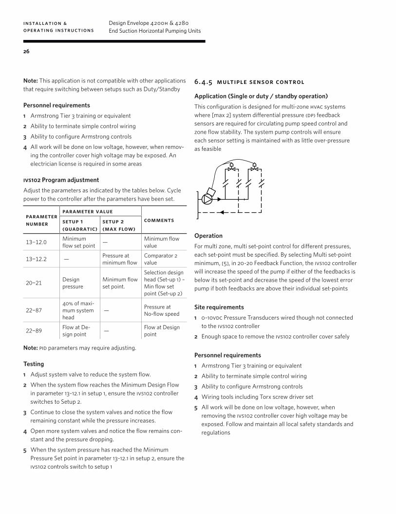
installation & operating instructions
Design Envelope 4200h & 4280End Suction Horizontal Pumping Units
26
Note: This application is not compatible with other applications that require switching between setups such as Duty/Standby
Personnel requirements1 Armstrong Tier 3 training or equivalent
2 Ability to terminate simple control wiring
3 Ability to configure Armstrong controls
4 All work will be done on low voltage, however, when remov-ing the controller cover high voltage may be exposed. An electrician license is required in some areas
ivs102 Program adjustmentAdjust the parameters as indicated by the tables below. Cycle power to the controller after the parameters have been set.
parameter number
parameter value comments setup 1
(quadratic) setup 2 (max flow)
13-12.0Minimum flow set point — Minimum flow
value
13-12.2 — Pressure at minimum flow
Comparator 2 value
20-21Design pressure
Minimum flow set point.
Selection design head (Set-up 1) – Min flow set point (Set-up 2)
22-8740% of maxi-mum system head
— Pressure at No-flow speed
22-89Flow at De-sign point — Flow at Design
point
Note: pid parameters may require adjusting.
Testing1 Adjust system valve to reduce the system flow.
2 When the system flow reaches the Minimum Design Flow in parameter 13-12.1 in setup 1, ensure the ivs102 controller switches to Setup 2.
3 Continue to close the system valves and notice the flow remaining constant while the pressure increases.
4 Open more system valves and notice the flow remains con-stant and the pressure dropping.
5 When the system pressure has reached the Minimum Pressure Set point in parameter 13-12.1 in setup 2, ensure the ivs102 controls switch to setup 1
6. 4 .5 multiple sensor control
Application (Single or duty / standby operation)This configuration is designed for multi-zone hvac systems where [max 2] system differential pressure (dp) feedback sensors are required for circulating pump speed control and zone flow stability. The system pump controls will ensure each sensor setting is maintained with as little over-pressure as feasible
OperationFor multi zone, multi set-point control for different pressures, each set-point must be specified. By selecting Multi set-point minimum, [5], in 20-20 Feedback Function, the ivs102 controller will increase the speed of the pump if either of the feedbacks is below its set-point and decrease the speed of the lowest error pump if both feedbacks are above their individual set-points
Site requirements1 0-10vdc Pressure Transducers wired though not connected
to the ivs102 controller
2 Enough space to remove the ivs102 controller cover safely
Personnel requirements1 Armstrong Tier 3 training or equivalent
2 Ability to terminate simple control wiring
3 Ability to configure Armstrong controls
4 Wiring tools including Torx screw driver set
5 All work will be done on low voltage, however, when removing the ivs102 controller cover high voltage may be exposed. Follow and maintain all local safety standards and regulations

installation & operating instructions
Design Envelope 4200h & 4280End Suction Horizontal Pumping Units
27
WiringWire the two Pressure Transducers as shown below.
ivs 102 - master ivs 102 - slave
(+24v dc) 12
(+24v dc) 13
analog in0-10vdc
analog in0-10vdc
analog incommon
53
54
(+24v dc) 12
(+24v dc) 13
analog in0-10vdc
analog in0-10vdc
analog incommon
53
54
note: Terminal 12 and 13 have a combined current limit of 200mA
Com
mon
Com
mon
Out
put
Out
put
Supp
lySu
pply
PT1
PT2
ivs102 controller programmingSet the parameters as indicated by the table below.
parameter number
parameter value comments
setup 1
6-14minimum sensor measurement range
Terminal 53 Low Ref./ Feedback value
6-15maximum sensor measurement range
Terminal 53 High Ref./ Feedback value
6-24minimum sensor measurement range
Terminal 54 Low Ref./ Feedback value
6-25maximum sensor measurement range
Terminal 54 High Ref./ Feedback value
20-02Measurement unit of external sensor Feedback 1 source unit
20-05Measurement unit of external sensor Feedback 2 source unit
20-20[5] Multi setpoint minimum Feedback function
20-21Design setpoint for sensor 1 Setpoint 1
20-22Design setpoint for sensor 2 Setpoint 2
Multiple [2] sensors with duty/standby configuration
For setup with Duty/Standby configuration, wire and program
the controllers as per the ‘Duty/Standby setup guide’. Wire the Pressure Transducers as shown in the diagram above. Program the additional parameters, specified above, to both controllers.
Testing1 Increasing a sensor set-point and verify the pump increases
speed to reach all set-points.
2 Decrease all set-points and verify the pump reduces speed to cover all set-points.
6. 4 .6 motor pre-heat application
ApplicationsThis configuration is ideal for protecting Design Envelope pumping unit motors in locations where ambient conditions cause condensation to occur in motors; particularly intermit-tently used close-coupled or short-coupled chilled water pump-ing units installed in regions with humid climate conditions
OperationManual method When an operator enables the feature from the keypad (lcp), the ivs102 controller will apply dc current to the motor when the motor is idle
Sensor methodWhen a site sensor has determined there is moisture present, the ivs102 controller will change to a setup where the pre-heat feature is enabled and will apply dc current to the motor when the motor stops.
When the sensor has determined moisture is no longer pres-ent. The ivs102 will change to a setup where the pre-heat feature is temporarily disabled
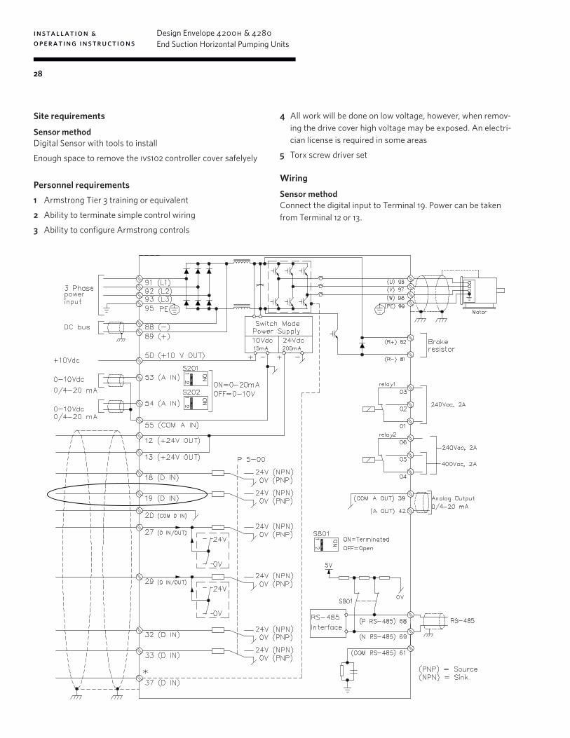
installation & operating instructions
Design Envelope 4200h & 4280End Suction Horizontal Pumping Units
28
Site requirements
Sensor methodDigital Sensor with tools to install
Enough space to remove the ivs102 controller cover safelyely
Personnel requirements1 Armstrong Tier 3 training or equivalent
2 Ability to terminate simple control wiring
3 Ability to configure Armstrong controls
4 All work will be done on low voltage, however, when remov-ing the drive cover high voltage may be exposed. An electri-cian license is required in some areas
5 Torx screw driver set
Wiring
Sensor methodConnect the digital input to Terminal 19. Power can be taken from Terminal 12 or 13.
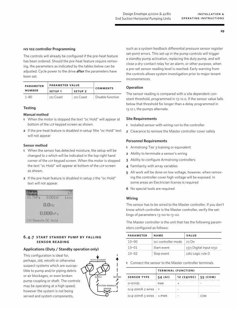
installation & operating instructions
Design Envelope 4200h & 4280End Suction Horizontal Pumping Units
29
ivs 102 controller Programming
The controls will already be configured if the pre-heat feature has been ordered. Should the pre-heat feature require remov-ing, the parameters as indicated by the tables below can be adjusted. Cycle power to the drive after the parameters have been set.
parameter number
parameter value comments
setup 1 setup 2 1–80 [0] Coast [0] Coast Disable function
Testing
Manual method1 When the motor is stopped the text “dc Hold” will appear at
bottom of the lcp keypad screen as shown.
2 If the pre-heat feature is disabled in setup 1the “dc Hold” text will not appear
Sensor method1 When the sensor has detected moisture, the setup will be
changed to 2 which will be indicated in the top right hand corner of the lcp keypad screen. When the motor is stopped the text “dc Hold” will appear at bottom of the lcp screen as shown.
2 If the pre-heat feature is disabled in setup 2 the “dc Hold” text will not appear.
6. 4 .7 start standby pump by falling sensor reading
Applications (Duty / Standby operation only)This configuration is ideal for, perhaps, old, retrofit or otherwise suspect systems which are suscep-tible to pump and/or piping debris or air blockages, or even broken pump coupling or shaft. The controls may be operating at a high speed; however the system is not being served and system components,
such as a system feedback differential pressure sensor register set-point errors. This set-up in the pump controls will trigger a standby pump activation, replacing the duty pump, and will close a dry-contact relay for an alarm, or other purpose, when a pre-set sensor reading level is reached. Early warning from the controls allows system investigation prior to major tenant inconveniences.
OperationThe sensor reading is compared with a site dependent con-stant threshold, programmed in 13-12.0. If the sensor value falls below that threshold for longer than a delay programmed in 13.12.1, the pumps alternate.
Site Requirements1 Installed sensor with wiring run to the controller
2 Clearance to remove the Master controller cover safely
Personnel Requirements1 Armstrong Tier 3 training or equivalent
2 Ability to terminate a sensor’s wiring
3 Ability to configure Armstrong controllers
4 Familiarity with array variables
5 All work will be done on low voltage, however, when remov-ing the controller cover high voltage will be exposed. In some areas an Electrician license is required
6 No special tools are required
WiringThe sensor has to be wired to the Master controller. If you don’t know which controller is the Master controller, verify the set-tings of parameters 13-00 to 13-02.
The Master controller is the unit that has the following param-eters configured as follows:
parameter name value
13-00 slc controller mode [1] On
13-01 Start event [37] Digital input di32
13-02 Stop event [26] Logic rule 0
1 Connect the sensor to the Master controller terminals
terminal (function)
sensor type 54 (ai) 12 (24vdc) 55 (com)
0-10Vdc pwr + -
0/4-20mA 2 wires + -
0/4-20mA 3 wires +/pwr - com
system feedbacksensor
duty/standby
supply return
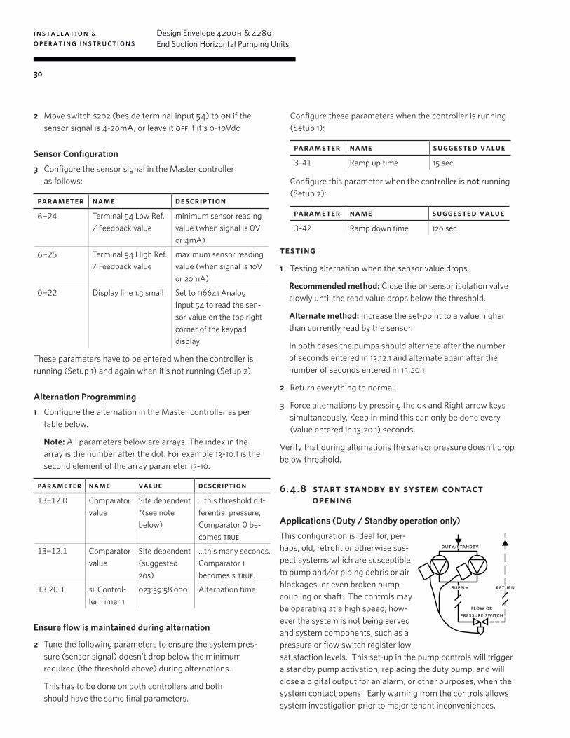
installation & operating instructions
Design Envelope 4200h & 4280End Suction Horizontal Pumping Units
30
2 Move switch s202 (beside terminal input 54) to on if the sensor signal is 4-20mA, or leave it off if it’s 0-10Vdc
Sensor Configuration3 Configure the sensor signal in the Master controller
as follows:
parameter name description
6-24 Terminal 54 Low Ref. / Feedback value
minimum sensor reading value (when signal is 0V or 4mA)
6-25 Terminal 54 High Ref./ Feedback value
maximum sensor reading value (when signal is 10V or 20mA)
0-22 Display line 1.3 small Set to [1664] Analog Input 54 to read the sen-sor value on the top right corner of the keypad display
These parameters have to be entered when the controller is running (Setup 1) and again when it’s not running (Setup 2).
Alternation Programming1 Configure the alternation in the Master controller as per
table below.
Note: All parameters below are arrays. The index in the array is the number after the dot. For example 13-10.1 is the second element of the array parameter 13-10.
parameter name value description
13-12.0 Comparator value
Site dependent*(see note below)
…this threshold dif-ferential pressure, Comparator 0 be-comes true.
13-12.1 Comparator value
Site dependent(suggested 20s)
…this many seconds, Comparator 1 becomes s true.
13.20.1 sl Control-ler Timer 1
023:59:58.000 Alternation time
Ensure flow is maintained during alternation
2 Tune the following parameters to ensure the system pres-sure (sensor signal) doesn’t drop below the minimum required (the threshold above) during alternations.
This has to be done on both controllers and both should have the same final parameters.
Configure these parameters when the controller is running (Setup 1):
parameter name suggested value
3–41 Ramp up time 15 sec
Configure this parameter when the controller is not running (Setup 2):
parameter name suggested value
3–42 Ramp down time 120 sec
testing
1 Testing alternation when the sensor value drops.
Recommended method: Close the dp sensor isolation valve slowly until the read value drops below the threshold.
Alternate method: Increase the set-point to a value higher than currently read by the sensor.
In both cases the pumps should alternate after the number of seconds entered in 13.12.1 and alternate again after the number of seconds entered in 13.20.1
2 Return everything to normal.
3 Force alternations by pressing the ok and Right arrow keys simultaneously. Keep in mind this can only be done every (value entered in 13.20.1) seconds.
Verify that during alternations the sensor pressure doesn’t drop below threshold.
6. 4 .8 start standby by system contact opening
Applications (Duty / Standby operation only)This configuration is ideal for, per-haps, old, retrofit or otherwise sus-pect systems which are susceptible to pump and/or piping debris or air blockages, or even broken pump coupling or shaft. The controls may be operating at a high speed; how-ever the system is not being served and system components, such as a pressure or flow switch register low satisfaction levels. This set-up in the pump controls will trigger a standby pump activation, replacing the duty pump, and will close a digital output for an alarm, or other purposes, when the system contact opens. Early warning from the controls allows system investigation prior to major tenant inconveniences.
flow orpressure switch
duty/standby
supply return
installation & operating instructions
Design Envelope 4200h & 4280End Suction Horizontal Pumping Units
31
OperationIf the contact opens for longer than a delay programmed in parameter 13.12.1, the pumps alternate.
At start up and after each alternation, the open contact is ignored for a period of time programmed in 13.20.1
If the contact stays open (the issue is not fixed by running the other pump), the pumps will continue to alternate every [time in seconds programmed in 13.20.1] until the issue is resolved
Site Requirements1 Switch already installed with wiring run to the pumps (but
not terminated)
2 Enough space to remove the Master drive cover safely
Personnel Requirements1 Armstrong Tier 3 training or equivalent
2 Ability to terminate simple control wiring
3 Ability to configure Armstrong drives
4 All work will be done on low voltage, however, when remov-ing the drive cover high voltage may be exposed. In some areas an Electrician license is required
5 No special tools are required
WiringThe contact wires have to be wired to the Master drive. If it’s unknown which drive is the Master drive, verify the settings of parameters 13-00 to 13-02.
The Master drive is the unit that has the following parameters configured as follows:
parameter name value
13–00 slc Controller Mode [1] On
13–01 Start Event [37] Digital input di32
13–02 Stop Event [26] Logic rule 0
1 Connect the switch to the Master drive terminals 12 (24Vdc output) and 19 (Digital Input)
2 24vdc output provided (Terminal 27) when contact opens
Site programming optionsConfigure the alternation in the Master drive as per the table below.
Note: All parameters below are arrays. The index in the array is the number after the dot. For example 13-10.1 is the second element of the array parameter 13-10.
parameter name value description
13-12.1 Comparator value
Site dependent(suggested 20s)
…this many sec-onds, Comparator 1 becomes true.
13.20.1 sl Controller timer 1
023:59:58.000 Alternation time
Ensure flow is maintained during alternation
1 Tune the following parameters to ensure the system pres-sure doesn’t drop below the minimum required (the thresh-old that opens the contact) during alternations.
This has to be done on both drives and both should have the same final parameters.
Configure these parameters when the drive is running (Setup 1):
parameter name suggested value
3–41 Ramp up time 15 sec
Configure this parameter when the drive is not running (Setup 2):
parameter name suggested value
3–42 Ramp down time 120 sec
Testing1 Testing alternation when the sensor value drops.
Recommended method: Close the flow / pressure switch isolation valve slowly until the contact opens.
Alternate method: Disconnect one of the contact wires from the ivs102 controls (terminals 12 and 19).
In both cases the pumping units should alternate after the number of seconds entered in 13.12.1 and alternate again every [number of seconds entered in 13.20.1]
2 Return everything to normal.
3 Force alternations by pressing the ok and Right arrow keys simultaneously. Keep in mind this can only be done every (value entered in 13.20.1) seconds.
Verify that during alternations the contact doesn’t open.
installation & operating instructions
Design Envelope 4200h & 4280End Suction Horizontal Pumping Units
32
7.0 warnings and alarms
A warning or an alarm is signalled by the relevant led on the front of the inverter and indicated by a code on the display.A warning remains active until its cause is no longer present. Under certain circumstances operation of the pump may still be continued. Warning messages may be critical, but are not necessarily so.
In the event of an alarm, the inverter will have tripped. Alarms must be reset to restart operation once their cause has been rectified. In many cases the auto reset function will restart the pump. Alternatively, the Reset button on the control panel can be pressed.
After a manual reset using the Reset button on the control panel, the Auto On button must be pressed to restart the pump.
If an alarm cannot be reset, the reason may be that its cause has not been rectified, or the alarm is trip-locked (see also table on following page).
Alarms that are trip-locked offer additional protection, means that the mains supply must be switched off before the alarm can be reset. After being switched back on, the inverter is no longer blocked and may be reset as described above once the cause has been rectified.
Alarms that are not trip-locked can also be reset using the automatic reset function in par. 14–20 Reset Mode (Warning: automatic wake-up is possible!) If a warning and alarm is marked against a code in the table on the following page, this means that either a warning occurs before an alarm, or it can be specified whether it is a warning or an alarm that is to be displayed for a given fault. This is possible, for instance, in par. 1–90 Motor Thermal Protection. After an alarm or trip, the motor carries on coasting, and the alarm and warning flash on the inverter. Once the problem has been rectified, only the alarm continues flashing.
7.1 fault messages
wa r n i n g 1, 10 Volts low:The 10 v voltage from terminal 50 on the control card is below 10 v. Remove some of the load from terminal 50, as the 10 v supply is over-loaded. Max. 15 ma or minimum 590 Ω.
wa r n i n g /a l a r m 2 , Live zero error:The signal on terminal 53 or 54 is less than 50% of the value set in par.6–10 Terminal 53 Low Voltage, par. 6–12 Terminal 53 Low Current, par.6–20 Terminal 54 Low Voltage, or par. 6–22 Terminal 54 Low Current respectively.
wa r n i n g /a l a r m 3 , No motor:No motor has been connected to the output of the inverter.
wa r n i n g /a l a r m 4 , Mains phase loss:A phase is missing on the supply side, or the mains voltage imbal-ance is too high. This message also appears in case of a fault in the input rectifier on the inverter. Check the supply voltage and supply currents to the inverter.
wa r n i n g 5 , d c link voltage high:The intermediate circuit voltage (dc) is higher than the over-volt-age limit of the control system. The inverter is still active.
wa r n i n g 6, dc link voltage low:The intermediate circuit voltage (dc) is below the under voltage limit of the control system. The inverter is still active.
wa r n i n g /a l a r m 7, dc over voltage:If the intermediate circuit voltage exceeds the limit, the inverter trips after a time.
wa r n i n g /a l a r m 8, dc under voltage:If the intermediate circuit voltage (dc) drops below the “voltage warning low” limit, the inverter checks if 24 v back-up supply is connected. If no 24 v backup supply is connected, the inverter trips after a given time depending on the unit.
wa r n i n g /a l a r m 9, Inverter overloaded:The inverter is about to cut out because of an overload (too high current for too long). The counter for electronic, thermal inverter protection gives a warning at 98% and trips at 100%, while giving an alarm. You cannot reset the inverter until the counter is below 90%. The fault is that the inverter is overloaded by more than nominal
wa r n i n g /a l a r m 10, Motor etr over temperature:According to the electronic thermal protection (etr), the motor is too hot. You can choose if you want the inverter to give a warning or an alarm when the counter reaches 100% in par. 1–90 Motor Thermal Protection. The fault is that the motor is overloaded by more than nominal current for too long. Check that the motor par. 1–24 Motor Current is set correctly.
wa r n i n g /a l a r m 11, Motor thermistor over temp:The thermistor or the thermistor connection is disconnected. You can choose if you want the inverter to give a warning or an alarm in par. 1-90 Motor Thermal Protection. Check that the thermistor is connected correctly between terminal 53 or 54 (analog voltage in-put) and terminal 50 (+ 10 Volts supply), or between terminal 18 or 19 (digital input pnp only) and terminal 50. If a kty sensor is used, check for correct connection between terminal 54 and 55.
wa r n i n g /a l a r m 12, Torque limit:The torque is higher than the value in par. 4–16 Torque Limit Motor Mode (in motor operation) or the torque is higher than the value in par.4–17 Torque Limit Generator Mode (in regenerative operation).
installation & operating instructions
Design Envelope 4200h & 4280End Suction Horizontal Pumping Units
33
wa r n i n g /a l a r m 13, Over Current:The inverter peak current limit (approx. 200% of the rated cur-rent) is exceeded. The warning will last approx. 8–12 sec., then the inverter trips and issues an alarm. Turn off the inverter and check if the motor shaft can be turned and if the motor size matches the inverter.
a l a r m 14, Earth fault:There is a discharge from the output phases to earth, either in the cable between the inverter and the motor or in the motor itself. Turn off the inverter and remove the earth fault.
a l a r m 15, In-complete hardware:A fitted option is not handled by the present control board (hard-ware or software).
a l a r m 16, Short-circuit:There is short-circuiting in the motor or on the motor terminals. Turn off the inverter and remove the short-circuit.
wa r n i n g /a l a r m 17, Control word timeout:There is no communication to the inverter.The warning will only be active when par. 8–04 Control Timeout Function is not set to off. If par. 8–04 Control Timeout Function is set to Stop and Trip, a warning appears and the inverter ramps down to zero speed, while giving an alarm. par. 8–03 Control Timeout Time could possibly be increased.
wa r n i n g 22, Hoist Mech. Brake:Report value will show what kind it is.0 = The torque ref. was not reached before timeout1 = There was no brake feedback before timeout.
wa r n i n g 23, Internal fans:External fans have failed due to defect hardware or fans not mounted.
wa r n i n g 24, External fan fault:The fan warning function is an extra protection function that checks if thefan is running / mounted. The fan warning can be disabled in par.14–53 Fan Monitor, [0] Disabled.
wa r n i n g 25, Brake resistor short-circuited:The brake resistor is monitored during operation. If it short- circuits, the brake function is disconnected and the warning appears. The inverter still works, but without the brake function. Turn off the inverter and replace the brake resistor (see par. 2–15 Brake Check).
a l a r m / wa r n i n g 26, Brake resistor power limit:The power transmitted to the brake resistor is calculated as a percentage, as a mean value over the last 120 s, on the basis of the resistance value of the brake resistor (par. 2–11 Brake Resistor (ohm)) and the intermediate circuit voltage. The warning is active when the dissipated braking power is higher than 90%. If Trip [2] has been selected in par. 2–13 Brake Power Monitoring, the inverter cuts out and issues this alarm, when the dissipated braking power is higher than 100%.
wa r n i n g /a l a r m 27, Brake chopper fault:The brake transistor is monitored during operation and if it short-circuits, the brake function disconnects and the warning comes up. The inverter is still able to run, but since the brake transistor has short-circuited, substantial power is transmitted to the brake resistor, even if it is inactive. Turn off the inverter and remove the brake resistor. Warning: There is a risk of substantial power being transmitted to the brake resistor if the brake transistor is short-circuited.
a l a r m / wa r n i n g 28, Brake check failed:Brake resistor fault: the brake resistor is not connected/working.
wa r n i n g /a l a r m 2 9 , Drive over temperature:If the enclosure isip00, ip20/Nema1 or ip21/type 1, the cut-out tem-perature of the heat-sink is 203°f +9°f (95°c +5°c). The tempera-ture fault cannot be reset, until the temperature of the heatsink is below 158°f (70°c). The fault could be: -Ambient temperature too high; -Too long motor cable
a l a r m 30, Motor phase U missing:Motor phase U between the frequency converter and the motor is missing.Turn off the frequency converter and check motor phase U.
a l a r m 31, Motor phase V missing:Motor phase V between the inverter and the motor is missing. Turn off the inverter and check motor phase V.
a l a r m 32, Motor phase W missing:Motor phase W between the inverter and the motor is missing. Turn off the frequency converter and check motor phase W.
a l a r m 3 3 , Inrush fault:Too many power ups have occured within a short time period.
wa r n i n g /a l a r m 34, Fieldbus communication fault:The fieldbus on the communication option card is not working.
wa r n i n g /a l a r m 36, Mains failure:This warning/alarm is only active if the supply voltage to the inverter is lost and par. 14–10 Mains Failure is not set to off. Possible correction: check the fuses to the frequency converter
wa r n i n g /a l a r m 37, Phase Imbalance:There is a current imbalance between the power units.
a l a r m 38, Internal fault:Contact your local Armstrong supplier.
a l a r m 39, Heatsink Sensor:No feedback from the heatsink sensor.
wa r n i n g 40, Overload of Digital Output Terminal 27:Check the load connected to terminal 27 or remove short-circuit connection. Check par. 5–00 Digital i/o Mode and par. 5–01 Terminal 27 Mode.

installation & operating instructions
Design Envelope 4200h & 4280End Suction Horizontal Pumping Units
34
wa r n i n g 41, Overload of Digital Output Terminal 29:Check the load connected to terminal 29 or remove short-circuit connection. Check par. 5–00 Digital i/o Mode and par. 5–02 Terminal 29 Mode.
wa r n i n g 42, Overload of Digital Output On x30/6 :Check the load connected to x30/6 or remove short-circuit connection. Check par. 5–32 Term X30/6 Digi Out (mcb 101).
wa r n i n g 42, Overload of Digital Output On x30/7 :Check the load connected to x30/7 or remove short-circuit con-nection. Check par. 5–33 Term x30/7 Digi Out (mcb 101).
a l a r m 46, Pwr. card supply:The supply on the power card is out of range.
wa r n i n g 47, 24 v supply low:The external 24 v dc backup power supply may be overloaded, otherwise contact your Armstrong supplier.
a l a r m 48, 1.8 v supply low:Contact your Armstrong supplier.
wa r n i n g 49, Speed limit:The speed has been limited by range in par. 4–11 Motor Speed Low Limit [rpm] and par. 4–13 Motor Speed High Limit [rpm ].
alarm 50, ama calibration failed:Contact your Armstrong supplier.
a l a r m 51, ama check Unom and Inom:The setting of motor voltage, motor current, and motor power is presumably wrong. Check the settings.
a l a r m 52, ama low Inom:The motor current is too low. Check the settings.
a l a r m 53, ama motor too big:The motor is too big for the ama to be carried out.
a l a r m 54, ama motor too small:The motor is too small for the ama to be carried out.
a l a r m 55, ama par. out of range:The par. values found from the motor are outside acceptable range.
a l a r m 56, ama interrupted by user:The ama has been interrupted by the user.
a l a r m 57, ama timeout:Try to start the ama again a number of times, until the ama is carried out. Please note that repeated runs may heat the motor to a level where the resistance rs and rr are increased. In most cases, however, this is not critical.
wa r n i n g /a l a r m 58, ama internal fault:Contact your Armstrong supplier.
wa r n i n g 59, Current limit:The current is higher than the value in par. 4–18 Current Limit.
wa r n i n g 60, External Interlock:External Interlock has been activated. To resume normal operation, apply 24 v dc to the terminal programmed for External Interlock and reset the inverter (via Bus, Digital i/o or by pressing Reset).
wa r n i n g /a l a r m 61, Tracking Error:Tracking error. Contact your supplier.
wa r n i n g 62, Output Frequency at Maximum Limit:The output frequency is limited by the value set in par. 4–19 Max Output Frequency
wa r n i n g 64, Voltage Limit:The load and speed combination demands a motor voltage higher than the actual dc link voltage.
wa r n i n g /a l a r m / t r i p 65, Control Card Over Temperature:Control card over temperature: The cut-out temperature of the control card is 176°f (80°c).
wa r n i n g 66, Heatsink Temperature Low:The heat sink temperature is measured as 32°f (0°c). This could indicate that the temperature sensor is defective and thus the fan speed is increased to the maximum in case the power part or control card is very hot. If the temperature is below 59°f (15°c) the warning will be present.
a l a r m 67, Option Configuration has Changed:One or more options has either been added or removed since the last power-down.
a l a r m 68, Safe Stop:Safe Stop has been activated. To resume normal operation, apply 24 vdc to terminal 37 then send a Reset signal (via Bus, Digital i/o or by pressing Reset).
a l a r m 69, Pwr. Card Temp:Power card over temperature.
a l a r m 70, Illegal Frequency Converter Configuration:Actual combination of control board and power board is illegal.
a l a r m 90, Feedback Mon.:
a l a r m 91, Analogue Input 54 Wrong Settings:Switch s202 has to be set in position off (voltage input), when a kty sensor is connected to the analogue input terminal 54.
installation & operating instructions
Design Envelope 4200h & 4280End Suction Horizontal Pumping Units
35
a l a r m 92, No Flow:A no load situation has been detected for the system. See parameter group 22–2*.
a l a r m 93, Dry Pump:A no flow situation and high speed indicates that the pump has run dry. See parameter group 22–2*.
a l a r m 94, End of Curve:Feed back stays lower than the set point, which may be indicates a leak-age in the pipe system. See parameter group 22–5*.
a l a r m 95, Broken Belt:Torque is below the torque level set for no load indicating a broken belt. See parameter group 22–6*.
a l a r m 96, Start Delayed:Start of the motor has been delayed due to short cycle protection is active. See parameter group 22–7*.
a l a r m 250, New Spare Part:The power or Switch Mode Power Supply has been exchanged. The inverter type code must be restored in the eeprom. Select the correct type code in par. 14–23 Type code Setting according to the label on unit. Remember to select ‘Save to eeprom’ to complete.
a l a r m 251, New Type Code:The frequency converter has got a new type code.
8.0 acoustic noise and vibration
If the pump or the pipework close to the pump is making noise or vibrations at certain frequencies, try the following:
• Speed Bypass, parameters 4– 6*• Over-modulation, parameter 14– 03 set to off• Switching pattern and frequency parameters 14– 0*• Resonance Dampening, parameter 1–64
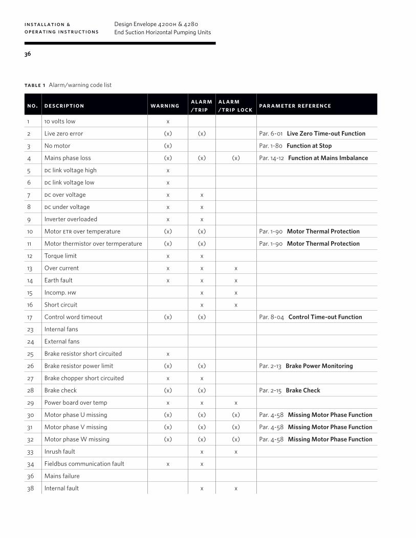
installation & operating instructions
Design Envelope 4200h & 4280End Suction Horizontal Pumping Units
36
table 1 Alarm/warning code list
no. description warning alarm/ trip
alarm/ trip lock par ameter reference
1 10 volts low x
2 Live zero error (x) (x) Par. 6-01 Live Zero Time-out Function
3 No motor (x) Par. 1-80 Function at Stop
4 Mains phase loss (x) (x) (x) Par. 14-12 Function at Mains Imbalance
5 dc link voltage high x
6 dc link voltage low x
7 dc over voltage x x
8 dc under voltage x x
9 Inverter overloaded x x
10 Motor etr over temperature (x) (x) Par. 1-90 Motor Thermal Protection
11 Motor thermistor over termperature (x) (x) Par. 1-90 Motor Thermal Protection
12 Torque limit x x
13 Over current x x x
14 Earth fault x x x
15 Incomp. hw x x
16 Short circuit x x
17 Control word timeout (x) (x) Par. 8-04 Control Time-out Function
23 Internal fans
24 External fans
25 Brake resistor short circuited x
26 Brake resistor power limit (x) (x) Par. 2-13 Brake Power Monitoring
27 Brake chopper short circuited x x
28 Brake check (x) (x) Par. 2-15 Brake Check
29 Power board over temp x x x
30 Motor phase U missing (x) (x) (x) Par. 4-58 Missing Motor Phase Function
31 Motor phase V missing (x) (x) (x) Par. 4-58 Missing Motor Phase Function
32 Motor phase W missing (x) (x) (x) Par. 4-58 Missing Motor Phase Function
33 Inrush fault x x
34 Fieldbus communication fault x x
36 Mains failure
38 Internal fault x x
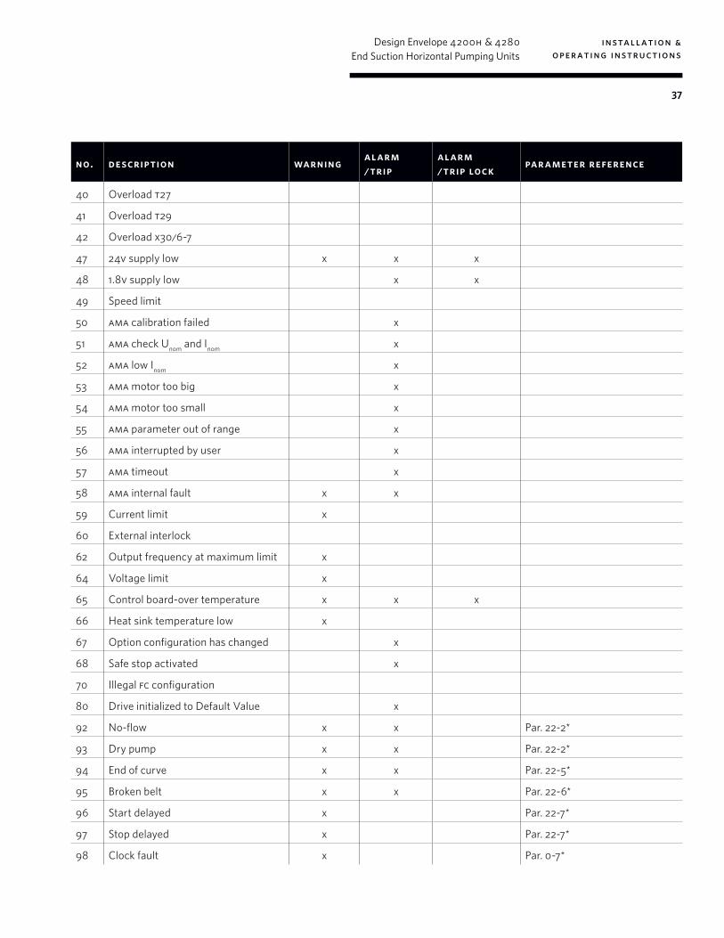
installation & operating instructions
Design Envelope 4200h & 4280End Suction Horizontal Pumping Units
37
no. description warning alarm/ trip
alarm/ trip lock par ameter reference
40 Overload t27
41 Overload t29
42 Overload x30/6-7
47 24v supply low x x x
48 1.8v supply low x x
49 Speed limit
50 ama calibration failed x
51 ama check Unom and Inom x
52 ama low Inom x
53 ama motor too big x
54 ama motor too small x
55 ama parameter out of range x
56 ama interrupted by user x
57 ama timeout x
58 ama internal fault x x
59 Current limit x
60 External interlock
62 Output frequency at maximum limit x
64 Voltage limit x
65 Control board-over temperature x x x
66 Heat sink temperature low x
67 Option configuration has changed x
68 Safe stop activated x
70 Illegal fc configuration
80 Drive initialized to Default Value x
92 No-flow x x Par. 22-2*
93 Dry pump x x Par. 22-2*
94 End of curve x x Par. 22-5*
95 Broken belt x x Par. 22-6*
96 Start delayed x Par. 22-7*
97 Stop delayed x Par. 22-7*
98 Clock fault x Par. 0-7*
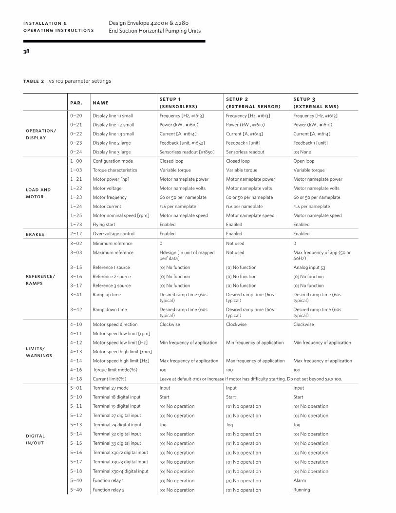
installation & operating instructions
Design Envelope 4200h & 4280End Suction Horizontal Pumping Units
38
par. name setup 1 (sensorless)
setup 2 (external sensor)
setup 3 (external bms)
operation/ display
0-20 Display line 1.1 small Frequency [Hz, #1613] Frequency [Hz, #1613] Frequency [Hz, #1613]
0-21 Display line 1.2 small Power (kW , #1610) Power (kW , #1610) Power (kW , #1610)
0-22 Display line 1.3 small Current [A, #1614] Current [A, #1614] Current [A, #1614]
0-23 Display line 2 large Feedback [unit, #1652] Feedback 1 [unit] Feedback 1 [unit]
0-24 Display line 3 large Sensorless readout [#1850] Sensorless readout [0] None
load and motor
1-00 Configuration mode Closed loop Closed loop Open loop
1-03 Torque characteristics Variable torque Variable torque Variable torque
1-21 Motor power [hp] Motor nameplate power Motor nameplate power Motor nameplate power
1-22 Motor voltage Motor nameplate volts Motor nameplate volts Motor nameplate volts
1-23 Motor frequency 60 or 50 per nameplate 60 or 50 per nameplate 60 or 50 per nameplate
1-24 Motor current fla per nameplate fla per nameplate fla per nameplate
1-25 Motor nominal speed [rpm] Motor nameplate speed Motor nameplate speed Motor nameplate speed
1-73 Flying start Enabled Enabled Enabled
brakes 2-17 Over-voltage control Enabled Enabled Enabled
reference/ramps
3-02 Minimum reference 0 Not used 0
3-03 Maximum reference Hdesign [in unit of mapped perf data]
Not used Max frequency of app (50 or 60Hz)
3-15 Reference 1 source [0] No function [0] No function Analog input 53
3-16 Reference 2 source [0] No function [0] No function [0] No function
3-17 Reference 3 source [0] No function [0] No function [0] No function
3-41 Ramp up time Desired ramp time (60s typical)
Desired ramp time (60s typical)
Desired ramp time (60s typical)
3-42 Ramp down time Desired ramp time (60s typical)
Desired ramp time (60s typical)
Desired ramp time (60s typical)
limits/ warnings
4-10 Motor speed direction Clockwise Clockwise Clockwise
4-11 Motor speed low limit [rpm]
4-12 Motor speed low limit [Hz] Min frequency of application Min frequency of application Min frequency of application
4-13 Motor speed high limit [rpm]
4-14 Motor speed high limit [Hz] Max frequency of application Max frequency of application Max frequency of application
4-16 Torque limit mode(%) 100 100 100
4-18 Current limit(%) Leave at default (110) or increase if motor has difficulty starting. Do not set beyond s.f.x 100.
digital in/out
5-01 Terminal 27 mode Input Input Input
5-10 Terminal 18 digital input Start Start Start
5-11 Terminal 19 digital input [0] No operation [0] No operation [0] No operation
5-12 Terminal 27 digital input [0] No operation [0] No operation [0] No operation
5-13 Terminal 29 digital input Jog Jog Jog
5-14 Terminal 32 digital input [0] No operation [0] No operation [0] No operation
5-15 Terminal 33 digital input [0] No operation [0] No operation [0] No operation
5-16 Terminal x30/2 digital input [0] No operation [0] No operation [0] No operation
5-17 Terminal x30/3 digital input [0] No operation [0] No operation [0] No operation
5-18 Terminal x30/4 digital input [0] No operation [0] No operation [0] No operation
5-40 Function relay 1 [0] No operation [0] No operation Alarm
5-40 Function relay 2 [0] No operation [0] No operation Running
table 2 ivs 102 parameter settings
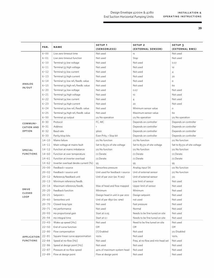
installation & operating instructions
Design Envelope 4200h & 4280End Suction Horizontal Pumping Units
39
par. name setup 1 (sensorless)
setup 2 (external sensor)
setup 3 (external bms)
analog in/out
6-00 Live zero timeout time Not used 1s Not used
6-01 Live zero timeout function Not used Stop Not used
6-10 Terminal 53 low voltage Not used Not used 0.07
6-11 Terminal 53 high voltage Not used Not used 10
6-12 Terminal 53 low current Not used Not used 4
6-13 Terminal 53 high current Not used Not used 20
6-14 Terminal 53 low ref./feedb. value Not used Not used 0
6-15 Terminal 53 high ref./feedb. value Not used Not used 60
6-20 Terminal 54 low voltage Not used 0.07 Not used
6-21 Terminal 54 high voltage Not used 10 Not used
6-22 Terminal 54 low current Not used 4 Not used
6-23 Terminal 54 high current Not used 20 Not used
6-24 Terminal 54 low ref./feedb. value Not used Minimum sensor value 0
6-25 Terminal 54 high ref./feedb. value Not used Maximum sensor value 60
6-50 Terminal 42 output [0] No operation [0] No operation [0] No operation
communi-cation and option
8-30 Protocol FC, MC Depends on controller Depends on controller
8-31 Address 1 Depends on controller Depends on controller
8-32 Baud rate 9600 Depends on controller Depends on controller
8-33 Parity/stop bits Even Prity, 1 Stop bit Depends on controller Depends on controller
special functions
14-10 Mains failure [0] No function [0] No function [0] No function
14-11 Main voltage at mains fault Set to 83.5% of site voltage Set to 83.5% of site voltage Set to 83.5% of site voltage
14-12 Function at mains imbalance [0] No function [0] No function [0] No function
14-60 Function at over temperature [1] Derate [1] Derate [1] Derate
14-61 Function at inverter overload [1] Derate [1] Derate [1] Derate
14-62 Inverter overload derate current (%) 95 95 95
drive closed loop
20-00 Feedback 1 source Sensorless pressure Analog input 54 [0] No function
20-02 Feedback 1 source unit Unit used for feedback 1 source Unit of external sensor [0] No function
20-12 Reference/feedback unit Unit of par 2021 (ex: ft wg) Unit of external sensor [0]
20-13 Minimum reference/feedb. Low limit of sensor Not used
20-14 Maximum reference/feedb. Max of head and flow mapped Upper limit of sensor Not used
20-20 Feedback function Minimum Minimum Not used
20-21 Setpoint 1 Design head in unit in par 2012 Design setpoint Not used
20-60 Sensorless unit Unit of par 1850 (ex: gpm) not used Not used
20-70 Closed-loop type Not used Fast pressure Not used
20-71 pid performance Not used Normal Not used
20-93 pid proportional gain Start at 0.05 Needs to be fine tuned on site Not used
20-94 pid integral time Start at 0.1 Needs to be fine tuned on site Not used
application functions
22-43 Wake up speed [Hz] Not used Need to be fine tuned on site Not used
22-50 End of curve function Off Off Off
22-80 Flow compensation [1] Enabled Not used [0] Disabled
22-81 Square-linear curve approximation 100% Not used 100%
22-84 Speed at no-flow [Hz] Not used Freq. at no flow and min head set Not used
22-86 Speed at design point [Hz] Not used Not used Not used
22-87 Pressure at no-flow speed 40% of maximum system head Not used Not used
22-89 Flow at design point Flow at design point Not used Not used

tm
a r m s t r o n g f lu i dt ec h n o lo g y. co ma r m s t r o n g f lu i d t ec h n o lo g y established 1934
b u f f a l o
t o r o n t o
m a n c h e s t e r
b a n g a l o r e
s h a n g h a i
s ã o p a u l o
#59, first floor, 3rd mainmargosa road, malleswarambangalore, india560 003+91 (0) 80 4906 3555
wolverton streetmanchesterunited kingdomm11 2et+44 (0) 8444 145 145
93 east avenuenorth tonawanda, new yorku.s.a.14120-6594+1 716 693 8813
23 bertrand avenuetoronto, ontariocanadam1l 2p3+1 416 755 2291
no. 1619 hu hang road, xi du townshipfeng xian district, shanghaip.r.c.201401+86 21 3756 6696
rua josé semião rodrigues agostinho, 1370 galpão 6embu das artessao paulo, brazil+55 11 4781 5500
b i r m i n g h a mheywood wharf, mucklow hillhalesowen, west midlandsunited kingdomb62 8dj+44 (0) 8444 145 145