Embed Size (px)
Citation preview

Rev. 3
DESIGN DESCRIPTION DOCUMENTFOR THE U.S. DUAL COOLANT Pb-17Li (DCLL)
TEST BLANKET MODULE
REPORT TO THEITER TEST BLANKET WORKING GROUP (TBWG)
byC.P.C. WONG, M. ABDOU, J. BLANCHARD, P. CALDERONI,
D.P. CAROSELLA, M. DAGHER, J. El-AWADY, P.J. FOGARTY,N. GHONIEM, R. KURTZ, M.P. LABAR, S. MAJUMDAR, S. MALANG,B. MERRILL, N.B. MORLEY, S. REYES, M. SAWAN, S. SHARAFAT,S. SMOLENTSEV, G. SVIATOSLAVSKY, D.K. SZE, M. ULRICKSON,
R.S. WILLMS, M. YOUSSEF, S.J. ZINKLE
NOVEMBER 15, 2005

DISCLAIMER
This report was prepared as an account of work sponsored by an agency of the United StatesGovernment. Neither the United States Government nor any agency thereof, nor any of their
employees, makes any warranty, express or implied, or assumes any legal liability or
responsibility for the accuracy, completeness, or usefulness of any information, apparatus,
product, or process disclosed, or represents that its use would not infringe privately owned rights.
Reference herein to any specific commercial product, process, or service by trade name,
trademark, manufacturer, or otherwise, does not necessarily constitute or imply its endorsement,
recommendation, or favoring by the United States Government or any agency thereof. The views
and opinions of authors expressed herein do not necessarily state or reflect those of the United
States Government or any agency thereof.

DESIGN DESCRIPTION DOCUMENTFOR THE U.S. DUAL COOLANT Pb-17Li (DCLL)
TEST BLANKET MODULEREPORT TO THE
ITER TEST BLANKET WORKING GROUP (TBWG)by
C.P.C. WONG,1 M. ABDOU,2 J. BLANCHARD,3 P. CALDERONI,2
D.P. CAROSELLA,1 M. DAGHER,2 J. El-AWADY,2 P.J. FOGARTY,4
N. GHONIEM,2 R. KURTZ,5 M.P. LABAR,1 S. MAJUMDAR,6 S. MALANG,7
B. MERRILL,8 N.B. MORLEY,2 S. REYES,9 M. SAWAN,3 S. SHARAFAT,2S. SMOLENTSEV,2 G. SVIATOSLAVSKY,3 D.K. SZE,10 M. ULRICKSON11
R.S. WILLMS,12 M. YOUSSEF,2 S.J. ZINKLE4
1General Atomics, San Diego, California USA2University of California, Los Angeles, California USA
3University of Wisconsin, Madison, Wisconsin USA4Oak Ridge National Laboratory, Oak Ridge, Tennessee USA
5Pacific Northwest Laboratory, Richland, Washington USA6Argonne National Laboratory, Argonne, Illinois USA
7Fusion Nuclear Technology Consulting, Linkenheim, Germany8Idaho National Laboratory, Idaho Falls, Idaho USA
9Lawrence Livermore National Laboratory, Livermore, California USA10University of California, San Diego, California USA
11Sandia National Laboratory, Albequerque, New Mexico USA12Los Alamos National Laboratory, Albequerque, New Mexico USA
Work supported bythe U.S. Department of Energy
under DE-FC02-04ER54698, DE-FG02-99ER54313,DE-AC05-76RL01830, DE-FG02-86ER52123,
DE-AC07-05ID14517, W-7405-ENG-48,DE-AC05-00OR22725
NOVEMBER 15, 2005


Design Description Document for the U.S. Dual Coolant Pb-17Li (DCLL) Test Blanket ModuleReport to the ITER Test Blanket Working Group (TBWG)
Rev. 3 iii
SUMMARY
The ITER Test Blanket Working Group (TBWG) requests that all parties interested in the Test
Blanket Module (TBM) program provide a design description document (DDD) for their selected
TBM option. For the liquid breeder design, reduced activation ferritic steel (FS) is selected as the
structural material, helium is selected as the first wall (FW) and blanket structure coolant, and Pb-
17Li is to be the self-cooled liquid breeder (DCLL). The concept is to be tested in one-half of a
designated test port. For the DCLL design, this blanket concept has the potential to satisfy the design
limits of FS which will then allow the possibility a high Pb-17Li outlet temperature. An outlet
temperature of 650oC to 700oC has the potential to lead to high thermal efficiency for a fusion power
reactor design. The U.S. TBM program objective is to generate adequate integrated testing data in a
progressive manner. The results can be used to provide a predictive capability for tritium breeding
blankets that can lead to the FW and blanket design for the DEMO and power producing reactor.
This DDD report includes a description of the functions and requirements of various design areas
and testing plans, the DCLL design, and corresponding analyses performed to support the design,
including necessary ancillary systems and equipment.
The U.S. strategy for ITER testing of the DCLL concept is flexible and still evolving. The test
plan must remain flexible in order to respond to technical issues that are revealed only during testing,
as well as budget issues that must also be accommodated. The approach is to design a series of
vertical half-port DCLL TBMs with dedicated ancillary equipment systems in transporter casks
behind the bioshield and in the TCWS building during the period of the first 10 years of ITER
operation. The consecutive modules that we envision are:
EM/S TBM: The first test module is an Electromagnetic/Structural (EM/S) module designed to
withstand and measure EM forces and the mechanical response of the TBM structure to various loads
during ITER hydrogen phase operations including: chamber conditioning, startup, shutdown, normal
discharges and transient effects including ELMs and disruption.
NT-TBM: Following the EM/S TBM, a Neutronics Testing (NT) TBM will be utilized during the D-
D phase and possibly the very beginning of the Low Duty Cycle D-T phases.
T/M TBM: At the beginning of the Low Duty Cycle D-T phase, a Thermofluid/MHD (T/M) TBM is
planned. The strategy for the T/M TBM is to allow testing of a variety of flow channel insert (FCI)
designs, geometries and integrated functions.
I TBM: During the High Duty Cycle D-T phase an Integrated (I) TBM is planned where the long-
term operation of the system is explored including some accumulation of radiation damage in the
FCI, and tritium and transmutation products in the Pb-17Li.
For the DCLL design and analysis reported, the focus has been on the I TBM design. Detailed
analyses were performed in the areas of nuclear analysis, thermal-hydraulic, MHD analysis of the
slowly circulating Pb-17Li, helium flow distribution, structural design and corresponding
electromagnetic impacts from disruption, including analysis on the system of tritium extraction.
The DCLL ancillary equipment assessment was based on the requirements of handling the FW
heat flux and maximizing the outlet temperature of the breeder coolant up to 650oC as well as the
evaluation of the ancillary systems and equipments required for two coolant loops. The first one is
the FW and structure helium coolant loop, which was designed to carry 54% of the total blanket
energy at the maximum ITER operation level. Dedicated helium piping is then designed between the

Design Description Document for the U.S. Dual Coolant Pb-17Li (DCLL) Test Blanket ModuleReport to the ITER Test Blanket Working Group (TBWG)
iv Rev. 3
TBM and the helium/water heat exchanger at the TCWS vault. The second one is the liquid breeder
loop, which was designed to carry 100% of the blanket energy at the maximum ITER operating level.
This second loop would also allow testing of a single breeder/coolant self-cooled breeder concept. For
this breeder loop, a helium intermediate heat removal circuit was designed between the breeder and
the TCWS water cooling system. Corresponding helium piping was also designed. The Pb-17Li flow
loop is planned to include a Pb-17Li bypass circuit so that the cold-leg Pb-17Li is mixed with the hot
Pb-17Li returning from the TBM before the Pb-17Li proceeds to the heat exchanger equipment in the
hot leg. In this way, the high temperature operation of the TBM itself can be explored, while the
added expense of the high temperature ancillary systems for heat and tritium extraction can be
deferred for testing in later phases of ITER operation beyond the first 10 years.
For this work, a safety assessment was performed on the design which provided guidance for the
TBM and ancillary equipment designs regarding minimizing the vulnerable breeder volume and the
potential loss of tritium through permeation. For the liquid breeder loop design, the requirement of
minimizing the potential tritium loss from the breeder to the vicinity led us to the use of the helium
intermediate heat transport loop. Concentric pipes were recommended to connect the liquid breeder
between the TBM and the breeder/helium heat exchanger. To minimize tritium permeation in the FW-
coolant loop, aluminum tubes are recommended for the He/water heat exchanger. A permeation
barrier like alumina coating or an Al sleeve is recommended for the helium-coolant inlet and outlet
piping. Results from the safety assessment for the ancillary equipment for the two FW/blanket
concepts show that ITER safety criterion can be met provided that we take care of controlling the
amount of breeder used in the system and the reduction of tritium permeation loss from the FW
coolant and liquid breeder loops.
In the US, we have also been interested in the development of dual coolant molten salt (DC)
liquid breeder/coolant first wall and blanket concepts. Ferritic steel was selected as the structural
material and helium was selected as the first wall and blanket structure coolant. In addition to
Pb-17Li, we evaluated a low melting point molten salt (LiBeF3) as a liquid breeder/coolant for a
backup liquid breeder option. Results of our assessment of necessary ancillary equipment are
summarized in Appendix C.

Design Description Document for the U.S. Dual Coolant Pb-17Li (DCLL) Test Blanket ModuleReport to the ITER Test Blanket Working Group (TBWG)
Rev. 3 v
TABLE OF CONTENT
SUMMARY ........................................................................................................................................ iii
1. FUNCTIONS AND REQUIREMENTS ................................................................................. 1-1
1.1. Functions ........................................................................................................................... 1-1
1.2. Design Requirements ........................................................................................................ 1-1
1.3. Safety Requirements ......................................................................................................... 1-1
1.4. Interface Requirements ..................................................................................................... 1-1
1.5. Other Requirements .......................................................................................................... 1-2
1.6. Proposed Test Plan in ITER .............................................................................................. 1-2
2. ENGINEERING DESCRIPTION ........................................................................................... 2-1
2.1. Summary of Overall Description ...................................................................................... 2-1
2.2. DCLL TBM ....................................................................................................................... 2-3
2.2.1. DCLL TBM Design ............................................................................................. 2-3
2.2.1.1. TBM Assembly .................................................................................. 2-5
2.2.1.2. The Coolant Circuits .......................................................................... 2-12
2.2.2. System Description .............................................................................................. 2-19
2.2.2.1. ITER Parameters ................................................................................ 2-19
2.2.2.2. Test Module Design Input Parameters for System Design ............... 2-19
2.2.2.3. Power Management and Intermediate Loop ..................................... 2-20
2.2.2.4. Ancillary System ................................................................................ 2-21
2.2.2.5. Helium Cooling Subsystems .............................................................. 2-26
2.2.2.6. DCLL Bypass System ........................................................................ 2-35
2.2.3. Component Description ....................................................................................... 2-36
2.2.3.1. Heat Exchanger .................................................................................. 2-36
2.2.3.2. Circulator ............................................................................................ 2-37
2.2.3.3. Electrical Heater ................................................................................. 2-38
2.2.3.4. Pipework ............................................................................................. 2-38
2.2.3.5. Valves ................................................................................................. 2-38
2.2.3.6. Pressure Control Unit ......................................................................... 2-38
2.2.3.7. Procurement Packaging ...................................................................... 2-39
2.2.4. Systems Design and Layout ................................................................................ 2-39
2.2.4.1. General Space Allocations and Description for TBM ...................... 2-39
2.2.4.2. Equatorial Test Port ............................................................................ 2-41
2.2.4.3. Pass-Through Design ......................................................................... 2-43
2.2.4.4. Bio-shield Plug ................................................................................... 2-44
2.2.4.5. Space Allocation of Equatorial Port Area ......................................... 2-44
2.2.4.6. Vertical Pipe Chase Area ................................................................... 2-46
2.2.4.7. TCWS Building Layout and Available Space ................................... 2-47
2.2.5. Procurement Package .......................................................................................... 2-48

Design Description Document for the U.S. Dual Coolant Pb-17Li (DCLL) Test Blanket ModuleReport to the ITER Test Blanket Working Group (TBWG)
vi Rev. 3
2.3. Tritium ............................................................................................................................... 2-49
2.3.1. Introduction .......................................................................................................... 2-49
2.3.2. Specifications ....................................................................................................... 2-49
2.3.3. Tritium Extraction Description ........................................................................... 2-50
2.3.4. Equipment Size .................................................................................................... 2-51
2.3.4.1. Tritium Extraction from Pb-17Li ....................................................... 2-51
2.3.4.2. Tritium Extraction from Helium Coolant .......................................... 2-51
2.3.4.3. Tritium Extraction from First Wall Helium ...................................... 2-51
2.3.5. Alternate Tritium Extraction Scheme ................................................................. 2-51
3. PERFORMANCE ANALYSIS ................................................................................................ 3-1
3.1. Nuclear Analysis ............................................................................................................... 3-1
3.1.1. Neutronics Calculation Procedure ...................................................................... 3-1
3.1.2. Tritium Breeding ................................................................................................. 3-2
3.1.3. Nuclear Heating ................................................................................................... 3-3
3.1.4. Structure Radiation Damage ............................................................................... 3-5
3.1.5. Shielding Requirement ........................................................................................ 3-6
3.1.6. Activation Calculation Procedure ....................................................................... 3-6
3.1.7. Radioactivity Inventory ....................................................................................... 3-9
3.1.8. Decay Heat Generation ....................................................................................... 3-11
3.1.9. Radwaste Assessment .......................................................................................... 3-14
3.1.10. Summary .............................................................................................................. 3-14
3.2. Thermo-Hydraulic Analysis ............................................................................................. 3-16
3.2.1. MHD Analysis ..................................................................................................... 3-16
3.2.1.1. Flow in the Poloidal Ducts with FCI ................................................. 3-16
3.2.1.2. MHD Pressure Drop in the Module ................................................... 3-16
3.2.1.3. Heat Transfer in the Concentric Pipe ................................................ 3-19
3.2.1.4. Heat Transfer in the Polodial Channels ............................................. 3-20
3.2.2. First Wall Helium Flow Distribution .................................................................. 3-22
3.2.2.1. First Wall Helium Flow Distribution Procedure ............................... 3-22
3.2.2.2. First Wall Helium Flow Distribution Results ................................... 3-22
3.2.3. Helium Circuit Pressure Drop Analysis ............................................................ 3-24
3.2.4. First Wall Thermal-Hydraulics Analysis ............................................................ 3-27
3.2.4.1. Steady State Analysis Procedure ....................................................... 3-27
3.2.4.2. First Wall Thermal-Hydraulic Analysis Results ............................... 3-28
3.2.4.3. Transient Phenomena Analysis Procedure ........................................ 3-28
3.2.4.4. Transient Phenomena Analysis Results ............................................. 3-29
3.3. Structural Analysis ............................................................................................................ 3-30
3.3.1. Stress Analysis ..................................................................................................... 3-30
3.3.2. Creep Damage Limits .......................................................................................... 3-33
3.3.3. Cyclic Creep-Ratcheting Limit ........................................................................... 3-35
3.3.4. Loss of Coolant Accident Consideration ............................................................ 3-37
3.4. Tritium Extraction Analysis .............................................................................................. 3-39
3.4.1. Analysis of Tritium Pathways for a Bubbler/Heat Exchanger Loop ................. 3-39

Design Description Document for the U.S. Dual Coolant Pb-17Li (DCLL) Test Blanket ModuleReport to the ITER Test Blanket Working Group (TBWG)
Rev. 3 vii
3.4.1.1. Physical Properties ............................................................................. 3-39
3.4.1.2. Model .................................................................................................. 3-39
3.4.1.3. Bubble Nucleation/Outgassing .......................................................... 3-44
3.4.1.4. Active versus Passive Tritium Removal ............................................ 3-44
3.4.1.5. Other Products .................................................................................... 3-45
3.4.1.6. Higher Temperatures .......................................................................... 3-45
3.4.1.7. Conclusions ........................................................................................ 3-45
3.4.2. Analysis of Tritium Permeation from Liquid Pb-17Li through a
Metal Membrane .................................................................................................. 3-45
3.4.2.1. System Description ............................................................................ 3-45
3.4.2.2. Model .................................................................................................. 3-45
3.4.2.3. Mass Transfer Coefficient .................................................................. 3-47
3.4.2.4. Results ................................................................................................ 3-47
3.4.2.5. Overall Permeator Considerations ..................................................... 3-53
3.4.2.6. Issues ................................................................................................... 3-53
3.4.2.7. Conclusions ........................................................................................ 3-54
3.4.2.8. Nomenclature ..................................................................................... 3-54
3.4.2.9. Mass Transfer Coefficient Correlation Evaluation ........................... 3-54
3.4.3. Permeation Extraction Equilibrium Analysis ..................................................... 3-57
3.4.3.1. Method of Analysis ............................................................................ 3-58
3.4.3.2. Diffusion Boundary Conditions and Material Properties ................. 3-59
3.4.3.3. Permeation Results ............................................................................. 3-61
3.5. Safety Analysis .................................................................................................................. 3-65
3.5.1. System Description and Source Terms Involved ............................................... 3-65
3.5.1.1. System Description ............................................................................. 3-65
3.5.1.2. Tritium Inventory ............................................................................... 3-67
3.5.1.3. Breeder Material Radioactive Inventory ........................................... 3-67
3.5.1.4. Structural Material Radioactive Inventory ........................................ 3-67
3.5.1.5. Chemical Energy and Hydrogen Sources .......................................... 3-68
3.5.1.6. Nuclear Energy Sources ..................................................................... 3-69
3.5.2. Accident Analyses ............................................................................................... 3-69
3.5.2.1. Method of Analysis ............................................................................ 3-69
3.5.2.2. TBM Accident Results ....................................................................... 3-72
3.5.3. Evaluation of Radiological Release .................................................................... 3-86
3.5.4. Uncertainties in Results ....................................................................................... 3-87
3.5.5. Summary .............................................................................................................. 3-87
4. DELIVERY AND REQUIRED R&D PLANS ...................................................................... 4-1
4.1. Test Plan and Requirements ............................................................................................. 4-1
4.2. Instrumentation Requirements .......................................................................................... 4-4
4.3. R&D Plan and Requirements ............................................................................................ 4-6
4.4. Hot Cell Requirements ...................................................................................................... 4-7

Design Description Document for the U.S. Dual Coolant Pb-17Li (DCLL) Test Blanket ModuleReport to the ITER Test Blanket Working Group (TBWG)
viii Rev. 3
APPENDIX A: UPDATED TBM FUNCTIONS AND DESIGN REQUIREMENTS
FROM 1997 US-TEST BLANKET PROGRAM, 1998 EU-HCPB AND
1997 EU-WCLL REPORTS .................................................................................................... A-1
APPENDIX B: ITER DCLL TBM CALCULATION SHEETS ................................................ B-1
APPENDIX C: ANCILLARY EQUIPMENT OF THE LiBeF3 DUAL
COOLANT CONCEPT ............................................................................................................ C-1
LIST OF FIGURES
2.1-1. DCLL TBM assembly installed in one of the half ports ................................................... 2-1
2.1-2. DCLL TBM sub-assemblies ............................................................................................... 2-2
2.2.1-1. DCLL TBM frame assembly .............................................................................................. 2-4
2.2.1-2. DCLL TBM assembly ........................................................................................................ 2-4
2.2.1-3. TBM support system .......................................................................................................... 2-4
2.2.1-4. DCLL TBM dimensions ..................................................................................................... 2-5
2.2.1-5. Section view at TBM midplane .......................................................................................... 2-5
2.2.1-6. TBM first wall assembly with internal He channel details ............................................... 2-6
2.2.1-7. Top plate assembly internal details .................................................................................... 2-7
2.2.1-8. Grid and separation plate assembly ................................................................................... 2-8
2.2.1-9. View showing the two sub-assemblies of the grid plate ................................................... 2-9
2.2.1-10. 3D view of the FCI components as they are arranged inside the TBM ............................ 2-10
2.2.1-11. FCI components, slip joint details ...................................................................................... 2-10
2.2.1-12. Back plate assembly ........................................................................................................... 2-11
2.2.1-13. View showing the inner and outer back plates .................................................................. 2-12
2.2.1-14. View of the He and Pb-17Li pipe assemblies .................................................................... 2-13
2.2.1-15. Section view of the TBM in the poloidal direction showing the
Pb-17Li flow circuit ........................................................................................................... 2-14
2.2.1-16. Section view of the lower Pb-17Li manifolds ................................................................... 2-14
2.2.1-17. 3D section view of the Pb-17Li concentric pipe with the SiC liner ................................. 2-14
2.2.1-18. 3D section view of the TBM showing the lower grid plate cutouts for the
Pb-17Li outlet flow ............................................................................................................. 2-15
2.2.1-19. Chart detailing the He flow circuit through the TBM ....................................................... 2-16
2.2.1-20. Back view of the TBM showing the He pipe arrangement ............................................... 2-16
2.2.1-21. He flow details in the outer back plate for FW He coolant in Circuit 1 ........................... 2-17

Design Description Document for the U.S. Dual Coolant Pb-17Li (DCLL) Test Blanket ModuleReport to the ITER Test Blanket Working Group (TBWG)
Rev. 3 ix
2.2.1-22. He flow details in the inner back plate for FW He flow of Circuit 2 ............................... 2-17
2.2.1-23. Top plate He flow details ................................................................................................... 2-18
2.2.1-24. Section view through the grid plate showing the He flow from the top
and bottom plates ................................................................................................................ 2-18
2.2.1-25. View of the grid plate showing the internal He channel details ....................................... 2-19
2.2.2-1. Pb-17Li system layout ........................................................................................................ 2-22
2.2.2-2. Piping from TBM to TCWS building ................................................................................ 2-27
2.2.2-3. Equatorial test port area with transporter ........................................................................... 2-27
2.2.2-4. Arrangement of piping and TBM ancillary equipment areas ............................................ 2-28
2.2.2-5. Helium cooling subsystem flow diagram .......................................................................... 2-29
2.2.2-6. The Pb-17Li loop ................................................................................................................ 2-29
2.2.2-7. DCLL TBM bypass loop schematic .................................................................................. 2-36
2.2.4-1. Test port general arrangement ............................................................................................ 2-40
2.2.4-2. Breeder coolant loop ........................................................................................................... 2-40
2.2.4-3. Coolant loop details ............................................................................................................ 2-41
2.2.4-4. Test module assembly ........................................................................................................ 2-42
2.2.4-5. Vacuum vessel plug ............................................................................................................ 2-43
2.2.4-6. Equatorial test port area with transporter ........................................................................... 2-45
2.2.4-7. Transporter side wall pipe penetrations to vertical pipe chase area .................................. 2-46
2.2.4-8. Pipe penetration into vertical pipe chase area .................................................................... 2-46
2.2.4-9. Equatorial port and pipe chase area ................................................................................... 2-47
2.2.4-10. TBM pipe run through TCWS area .................................................................................... 2-47
2.2.4-11. U.S. TBM primary and secondary coolant loops in TCWS .............................................. 2-48
2.2.4-12. Primary and secondary coolant loops plan view ............................................................... 2-49
2.3.3-1. Functional flow diagram of the tritium system ................................................................. 2-50
3.1-1. Internal structure of the DCLL TBM ................................................................................. 3-1
3.1-2. Radial variation of tritium production rate in Pb-17Li ...................................................... 3-3
3.1-3. Radial distribution of power density in constituent materials
of the DCLL TBM .............................................................................................................. 3-3
3.1-4. Nuclear heating in TBM components ................................................................................ 3-4
3.1-5. Radial variation of damage rates in the ferritic steel structure of the TBM ..................... 3-5
3.1-6. Radial variation of damage rates in the piping region and shield plug behind
the DCLL TBM .................................................................................................................. 3-5

Design Description Document for the U.S. Dual Coolant Pb-17Li (DCLL) Test Blanket ModuleReport to the ITER Test Blanket Working Group (TBWG)
x Rev. 3
3.1-7. Variation of neutron flux with shield plug thickness ........................................................ 3-6
3.1.7-1. Total activity generated in the test blanket module ........................................................... 3-10
3.1.7-2. Total activity in the F82H structure and contribution from each zone ............................. 3-10
3.1.7-3. Total activity in the Pb-17Li breeder and contribution from each zone ........................... 3-11
3.1.8-1. Total afterheat generated in the test blanket module ......................................................... 3-12
3.1.8-2. Total afterheat in the F82H structure ................................................................................. 3-13
3.1.8-3. Total afterheat in the Pb-17Li breeder ............................................................................... 3-13
3.2.1-1. MHD flow in the front poloidal channel with FCI ............................................................ 3-17
3.2.1-2. Cross-section of the concentric pipe .................................................................................. 3-19
3.2.1-3. Cross-sectional temperature distribution in the concentric pipe ....................................... 3-20
3.2.1-4. Bulk temperature in the polodial channel .......................................................................... 3-20
3.2.1-5. Temperature at the exit of the front channel ...................................................................... 3-21
3.2.1-6. Radial temperature distribution .......................................................................................... 3-21
3.2.2-1. Schematic layout of one first wall He flow circuit ............................................................ 3-23
3.2.2-2. CFD header model .............................................................................................................. 3-23
3.2.2-3. Header outlet channel flow distribution ............................................................................. 3-24
3.2.3-1. TBM He cooling circuits .................................................................................................... 3-25
3.2.4-1. Five-pass steady state FW CFD model schematic ............................................................ 3-27
3.2.4-2. First wall temperature contours .......................................................................................... 3-28
3.2.4-3. Two pass FW transient phenomena CFD model schematic .............................................. 3-29
3.3-1. Helium coolant temperatures and thermo-hydraulic parameters used for the
thermo-mechanical FEM analysis of the DCLL ITER-TBM ........................................... 3-30
3.3-2. Details of the meshed FEM of a 5-channel section near the top of the DCLL
ITER TBM .......................................................................................................................... 3-31
3.3-3. Temperatures of a 5-channel section located at the top of the DCLL module ................. 3-32
3.3-4. Primary plus secondary Von Mises stress distribution of a 5-channel section ................ 3-32
3.3-5. Stress breakdown ................................................................................................................ 3-33
3.3-6. Bending shape factor for first wall cross-section .............................................................. 3-34
3.3-7. Average ultimate tensile and yield stress for F82H .......................................................... 3-34
3.3-8. Time-dependent primary stress values for 10,000 and 30,000 h ...................................... 3-35
3.3-9. Net displacements of the 5-channel section located at the top of the DCLL module ...... 3-36
3.3-10. FEM of the entire DCLL TBM for LOCA analysis .......................................................... 3-37
3.3-11. DCLL displacement and Von Mises stress due to LOCA inside the TBM ...................... 3-38

Design Description Document for the U.S. Dual Coolant Pb-17Li (DCLL) Test Blanket ModuleReport to the ITER Test Blanket Working Group (TBWG)
Rev. 3 xi
3.3-12. Reduction of maximum Von Mises stress from 612 to 415 MPa ..................................... 3-38
3.4.1-1. DCLL tritium extraction system flow diagram ................................................................. 3-40
3.4.1-2. Tritium partial pressure variation in time .......................................................................... 3-41
3.4.1-3. Equilibrium partial pressure and partial pressure of tritium versus time .......................... 3-42
3.4.1-4. Tritium partial pressure history .......................................................................................... 3-43
3.4.1-5. Downstream tritium pressure history ................................................................................. 3-43
3.4.1-6. Tritium removal through different pathways ..................................................................... 3-44
3.4.2-1. Important features of the permeator ................................................................................... 3-46
3.4.2-2. Mechanism of tritium removal from Pb-17Li ................................................................... 3-46
3.4.2-3. Mass fraction of tritium in Pb-17Li ................................................................................... 3-48
3.4.2-4. Mass fraction and equilibrium partial of tritium in Pb-17Li ............................................. 3-49
3.4.2-5. Mass fraction of tritium versus mass transfer coefficients ................................................ 3-50
3.4.2-6. Mass fraction of tritium versus wall thickness .................................................................. 3-50
3.4.2-7. Mass fraction of tritium versus permeability ..................................................................... 3-50
3.4.2-8. Mass fraction of tritium at the membrane surface and in the bulk of Pb-17Li ................. 3-51
3.4.2-9. Mass fraction of tritium versus Pb-17Li flow rate ............................................................ 3-52
3.4.2-10. Mass fraction of tritium as function of tube diameter ....................................................... 3-52
3.4.2-11. Mass fraction of tritium at different permeate pressure .................................................... 3-53
3.4.2-12. Mass fraction of tritium versus tritium feed concentration ............................................... 3-53
3.4.2-13. Mass transfer coefficient from different references .......................................................... 3-57
3.4.3-1. Schematic diagram of the TMAP model developed for assessing DCLL
TBM permeation ................................................................................................................. 3-58
3.4.3-2. Tritium pressure and expanded view of the first 50 pulses showing
tritium pressure above Pb-17Li in the TBM for the case with no permeation
barrier on TBM system piping ........................................................................................... 3-62
3.4.3-3. Tritium release rate from TBM system piping for the case with
no permeation barriers ........................................................................................................ 3-62
3.4.3-4. Tritium pressure and expanded view of the first 50 pulses showing tritium pressure
above Pb-17Li in the TBM for the case with perfect permeation barriers on
TBM system piping ............................................................................................................ 3-63
3.4.3-5. TBM system tritium inventory ........................................................................................... 3-63
3.5-1. Schematic diagram of MELCOR model developed for assessing DCLL TBM safety ... 3-70
3.5-2. Coolant temperatures predicted by MELCOR for a TBM high temperature
operating scenario ............................................................................................................... 3-72

Design Description Document for the U.S. Dual Coolant Pb-17Li (DCLL) Test Blanket ModuleReport to the ITER Test Blanket Working Group (TBWG)
xii Rev. 3
3.5-3. TBM FW helium and VV pressures during an in-vessel TBM coolant leak accident ..... 3-73
3.5-4. ITER VV pressuring during a multiple tube in-vessel LOCA .......................................... 3-74
3.5-5. TBM FW break flow and integrated TBM FW break flow .............................................. 3-74
3.5-6. TBM FW maximum temperature and TBM FW beryllium total hydrogen generation ... 3-74
3.5-7. TBM breeder zone pressure, and drain tank, port cell and VV pressure .......................... 3-75
3.5-8. TBM FW temperature, and Pb-17Li volumes during an in-vessel TBM coolant leak .... 3-76
3.5-9. Peak VV pressure comparison during an in-vessel TBM coolant leak accident .............. 3-76
3.5-10. TBM FW helium and TBM breeder zone pressures during an in-blanket
TBM coolant leak accident ................................................................................................ 3-79
3.5-11. Test cell, TCWS vault, and drain tank helium masses ...................................................... 3-79
3.5-12. TBM FW temperature, and FW beryllium clad thickness and hydrogen generation ....... 3-79
3.5-13. TBM FW temperature comparison between variant and base cases ................................ 3-81
3.5-14. Test cell, TCWS vault and VV pressures, and expanded view following break .............. 3-82
3.5-15. Test cell and TCWS vault helium masses, and steam masses .......................................... 3-83
3.5-16. FW and second wall temperatures, and FW hydrogen production ................................... 3-83
3.5-17. TBM breeder zone pressure, and FW temperature comparisons ...................................... 3-84
3.5-18. Pb-17Li volume and VV pressure comparison .................................................................. 3-84
3.5-19. Test cell and TCWS vault pressures and FW temperature comparison ........................... 3-85
3.5-20. DCLL TBM FW temperature evolution due to decay heat ............................................... 3-86
4.1-1. Fluence requirements .......................................................................................................... 4-3
LIST OF TABLES
2.2.2-1. TBM coolant design parameters ........................................................................................ 2-20
2.2.2-2. Pb-17Li flow system specifications ................................................................................... 2-22
2.2.2-3. Pb-17Li/He heat exchanger ................................................................................................ 2-24
2.2.2-4. Design parameters of FW and LB cooling subsystem ...................................................... 2-30
2.2.2-5. First wall helium cooling loop pressure loss and helium inventory under
extreme operating conditions ............................................................................................. 2-31
2.2.2-6. Enveloping dimensions and weights of the first wall helium cooling
loop components ................................................................................................................. 2-31
2.2.2-7. Space requirements and supplies to DCLL helium cooling subsystem ............................ 2-34
2.2.2-8. Heat losses from the first wall cooling subsystem for different operational conditions .. 2-35

Design Description Document for the U.S. Dual Coolant Pb-17Li (DCLL) Test Blanket ModuleReport to the ITER Test Blanket Working Group (TBWG)
Rev. 3 xiii
2.2.3-1. Heat exchanger layout data ................................................................................................ 2-37
2.2.4-1. Vacuum vessel plug penetration summary ........................................................................ 2-43
2.2.4-2. Equatorial port transporter equipment summary ............................................................... 2-45
2.2.4-3. Transporter pipe penetration summary .............................................................................. 2-45
2.2.4-4. Primary and secondary coolant loops equipment summary .............................................. 2-48
2.3.2-1. Tritium recovery specifications .......................................................................................... 2-49
3.1-1. Radial build and composition used in the neutronics calculations ................................... 3-2
3.1-2. Peak power densities in TBM constituent materials ......................................................... 3-4
3.1-3. Nuclear heating in TBM components during 500 MW D-T pulse ................................... 3-4
3.1.6-1. The impurities considered in the F82H structure .............................................................. 3-7
3.1.6-2. Impurities considered in the Pb-17Li, 90% Li-6 breeder and the SiC insert .................... 3-7
3.1.7-1. Radioactivity inventory in the TBM at shutdown ............................................................. 3-9
3.1.8-1. Afterheat in the TBM at shutdown .................................................................................... 3-12
3.2.1-1. MHD pressure drops in the TBM ...................................................................................... 3-19
3.2.3-1. Summary of pressure drop in the helium circuit ............................................................... 3-26
3.2.4-1. Material properties used in the model ................................................................................ 3-28
3.2.4-2. Comparison of steady state and transient phenomena results ........................................... 3-29
3.3-1. Thermal hydraulic parameters used for DCLL thermal conduction and stress analysis .. 3-31
3.3-2. Summary of DCLL 5-channel section temperatures and stresses .................................... 3-33
3.3-3. Primary plus secondary stress limits .................................................................................. 3-36
3.4.2-1. Tritium assessment base case ............................................................................................. 3-48
3.4.2-2. Input parameters for mass transfer coefficient calculation ............................................... 3-55
3.5-1. Energy sources for the DCLL TBM .................................................................................. 3-69
3.5-2. Radial build of CHEMCON thermal model of DCLL TBM ............................................ 3-71
4.1-1. U.S. DCLL TBM schedule during first 10 years of ITER operation ................................ 4-2
4.2-1. Location of instrumentations in response to different monitoring and testing areas ....... 4-5
4.4-1. Miniature specimens for assessing the effect of the ITER service environment on
TBM design and materials ................................................................................................. 4-8


Design Description Document for the U.S. Dual Coolant Pb-17Li (DCLL) Test Blanket ModuleReport to the ITER Test Blanket Working Group (TBWG)
Rev. 3 1-1
1. FUNCTIONS AND REQUIREMENTS
The design and assessment of suitable TBMs to be tested in ITER have been initiated during
ITER-CDA and ITER-EDA studies. The design requirements of all ITER components are described
in the General Design Requirement Document (GDRD) [1-1]. In addition to these general
requirements, there are special requirements for the TBM which are also specific to a particular
blanket concept to be tested in ITER. General and specific functions and requirements have been
listed in the 1997 U.S.-Test Blanket Program [1-2], 1998 EU-HCPB [1-3] and 1997 EU-WCLL [1-4]
reports. To complete the descriptions of the functions and requirements for the DCLL and HCPB
designs, earlier reports were reviewed and updated. Details are presented in Appendix A.
1.1. FUNCTIONS
The principle function of the U.S. TBM is to generate integrated testing data in a progressive
manner and the results can be used to provide a predictive capability for tritium breeding first wall
and blanket designs that are relevant to a DEMO and power producing reactor. Related to this
principle are different specific functions related to tritium breeding, nuclear performance, heat
removal and material performance. These are provided in detail in Appendix A.
1.2. DESIGN REQUIREMENTS
The design requirements of all ITER components are described in the General Design
Requirement Document (GDRD) [1-1]. Appendix A lists specific requirements for the DCLL and
HCPB designs covering the areas of vacuum, structural, electromagnetic, thermal-hydraulic,
mechanical, electrical, nuclear, remote handling, transporter, chemical, seismic, manufacturing,
construction, assembly, testing, instrumentation and control, decommissioning, electrical connections.
1.3. SAFETY REQUIREMENTS
The safety requirements for the TBM System are derived from the ITER General Safety and
Environmental Design Criteria (GSEDC), the General Design Requirements Document (GDRD)
[1-1], the Plant Safety Requirements (PSR), and functional safety requirements (confinement, fusion
power shutdown, decay heat removal, monitoring, and control of chemical energies) which are
necessary for ITER. All criteria and requirements built upon these fundamental safety principles are
listed in Appendix A.
1.4. INTERFACE REQUIREMENTS
In order to successfully complete all test objectives, the TBM System must work in cooperation
with many of the other ITER systems and facilities. These interrelationships are many and complex,
involving both geometric and functional requirements. Requirements for the system interfaces include
vacuum vessel, remote handling equipment, cryostat, primary heat transport system, vacuum pumping
system, tritium plant, tokamak operations and control, building and general testing equipment are
described in Appendix A.

Design Description Document for the U.S. Dual Coolant Pb-17Li (DCLL) Test Blanket ModuleReport to the ITER Test Blanket Working Group (TBWG)
1-2 Rev. 3
1.5. OTHER REQUIREMENTS
Appendix A describes other requirements for the DCLL design which include considerations in
the containment of tritium and activation products, different purification circuits, confinement of
ancillary circuits, guard heating and insulating of the Pb-17Li circuit.
1.6. PROPOSED TEST PLAN IN ITER
A description of the DCLL test and R&D plan is presented in Section 4 of this report.
Functions of the test plan include carrying out the TBM tests efficiently in concert with the ITER
operation and requirements.
Requirements of the test plan are:
• The test plan must be adaptive and flexible to react to changes in the experimental program of
ITER, previous test results, schedules and issues in R&D, fabrication, mock-up testing and
budget support.
• The test plan is required to specify in detail all TBMs and their objectives as well as test
schedules in ITER.
• The test plan should be well documented and updated regularly for various milestones using a
common project software such as Microsoft Office or similar.
• The test plan is required to specify schedules to ensure each test module and required ancillary
equipment are fabricated, tested and qualified on time for installation into the ITER testing
ports.
• The test plan is required to specify ancillary equipment including diagnostics and wiring
attachments for each TBM installation.
• The test plan is required to specify dedicated ITER operations required for specific TBM tests
and test series.
• The test plan is required to specify operational settings for all ancillary, diagnostics and
monitoring equipment for the series of experiments to be performed for each TBM.
• The test plan is required to specify installation and removal procedures of each TMB,
including required PIE, samples to be retained, and ultimate disposal.
References for Section 1
[1-1] Design Requirements and Guidelines Level 1 (DRG1) G A0 GDRD 2 01-07-13 R 1.0.
[1-2] U.S. Contribution to Test Blanket Program, Draft ITER Test Blanket Program GDRD Test
Blanket System DDD, U.S. Proposal on Solid Breeder Blanket Test Program, Test Program
Proposal for U.S. Liquid Breeder (Li/V) and U.S. Proposal on Neutronics Test, UCLA-FNT-
132, October 1995.
[1-3] European Helium Cooled Pebble Bed (HCPB) Test Blanket, ITER Design Description
Document Status, 1.12.1998, Forschungszentrum Karlsruhe, FZKA 6127, 1999.
[1-4] European Water Cooled PbLi (WCLL) Test Blanket, 1997. Personal communication from
Dr. Yves Poitevin of EFDA.

Design Description Document for the U.S. Dual Coolant Pb-17Li (DCLL) Test Blanket ModuleReport to the ITER Test Blanket Working Group (TBWG)
Rev. 3 2-1
2. ENGINEERING DESCRIPTION
2.1. SUMMARY OF OVERALL DESCRIPTION
In support of the ITER Test Blanket Module (TBM) program, the U.S. has been focusing on the
dual coolant Pb-17Li liquid breeder (DCLL) blanket design, a concept that has been explored
extensively in the U.S. [2.1-1, 2.1-2] and by the European Union [2.1-3]. Detailed description of the
U.S. DCLL TBM design is presented in this report. Reduced Activation Ferritic Steel (FS) is selected
as the structural material and helium is selected as the first wall and blanket structure coolant. We
propose to test the concept in one half of a designated test port as shown in Fig. 2.1-1. It is mounted
inside a water cooled frame designed to hold two different test modules. The front surface of the
module is 64.5 cm wide and 186.4 cm high. The total radial depth of the TBM is 41.3 cm followed by
a 30 cm thick inlet/outlet piping zone. A separate 316SS/H2O shield plug is used behind the TBM. A
2 mm-thick beryllium layer is utilized as a plasma facing component (PFC) material on the FS first
wall.
Fig. 2.1-1. DCLL TBM assembly installed in one of the half ports.
A drawing of the DCLL sub-assemblies is shown in Fig. 2.1-2. The sub-assemblies will form the
box structure of the TBM. The support key as shown in Fig. 2.1-2 will be inserted into matching slot
in the Shielding block located behind the TBM, and the four positioning pins will be inserted into the
shielding block and used to set the TBM into the proper position and provide the radial support
needed at the top and bottom during operation. The TBM is designed to accommodate two fluid
flows internally and maintain the total separation between them. Details of the mechanical design are
given in Section 2.2.1. The module is also designed to withstand the maximum He pressures in case
of an internal leak from the He into the Pb-Li chambers described in Section 3.3.
Detail description of the coolant loop systems and ancillary equipments necessary to support the
DCLL and corresponding systems and equipment at the TCWS vault is presented in Sections 2.2.2
and 2.2.3.
The first wall and structure helium loop will be a self-contained loop including heat transport,
tritium extraction, helium purification, and heat exchanger to the TCWS plant cooling water. This
system is designed to extract about 54% of the total power generated in the one-half module.

Design Description Document for the U.S. Dual Coolant Pb-17Li (DCLL) Test Blanket ModuleReport to the ITER Test Blanket Working Group (TBWG)
2-2 Rev. 3
Fig. 2.1-2. DCLL TBM sub-assemblies.
To avoid long liquid breeder pipes running from the TBMs to the heat exchanger in the TCWS,
we decided to utilize a helium coolant intermediate loop. A liquid breeder to helium heat exchanger
is located close to the test module to minimize the amount of liquid breeder and the corresponding
loss of tritium to the surroundings. The liquid breeder transport loop is designed to extract 100% of
the total power generated in the one-half module. This allows the possibility for the testing of a
complete self-cooled liquid breeder design option. To avoid the use of advanced materials for the
handling of high temperature Pb-17Li, a bypass loop system is proposed. Hot Pb-17Li returning from
the TBM is mixed with the bypassed cold Pb-17Li at the bypass section, resulting in only a warm
stream going to the tritium extraction and heat exchange systems. In this way, the high temperature
features of the TBM, especially the function of the SiC composite flow channel insert, as a thermal
insulator at high temperature, can be tested in ITER without requiring high temperature materials in
the tritium extraction and heat exchanger systems. This bypass system is described in Section 2.2.2.4.
The TBM is connected to the transporter through series of pipes providing all the needed service
mainly for cooling and diagnostics. These pipes must penetrate two barriers as they are routed
between the transporter and the TBM. The U.S. TBM design relies on the two coolant loops and
purge lines to provide all the operational services needed. Description of the necessary components
needed on the transporter, including pumps, heat exchangers, tritium extraction system and other
supporting equipment is given in Sections 2.2.2 and 2.2.3.
A space of 16.6 7.3 m with a clear height of 5 m is assigned in the south end of the TCWS
building for all TBM cooling system. This space is shared with all the parties to house the
corresponding cooling systems. The DCLL TBM design requires a primary and secondary He
coolant loops are located in this area. Necessary equipments including heat exchangers, helium
heating unit, pressure control sub-systems, tritium extraction sub-system and various flow meters
were specified, and presented in Section 2.2.3. The tritium processing and extraction system for both
primary and secondary coolant loops are also located in the TCWS area.

Design Description Document for the U.S. Dual Coolant Pb-17Li (DCLL) Test Blanket ModuleReport to the ITER Test Blanket Working Group (TBWG)
Rev. 3 2-3
References for Section 2.1
[2.1-1] M.S. Tillack, S. Malang, "High Performance PbLi Blanket," Proc. 17th IEEE/NPSS Symp.
on Fusion Energy, San Diego, California, 1997 (Institute of Electrical and Electronics
Engineers, Inc. 1998) Vol. 2, p. 1000.
[2.1-2] D.K. Sze, M. Tillack, et al., "Blanket system selection for ARIES ST," Fusion Engin. and
Design 48 (2000) 371.
[2.1-3] P. Norajitra, et al., "The EU advanced dual coolant blanket concept," Fusion Engin. and
Design 61-62 (2002) 449.
2.2. DCLL TBM
2.2.1. DCLL TBM Design
The Dual Coolant, Pb-17Li (DCLL) TBM is designed using low activation ferritic steel as
structural material and He as a coolant for the first wall and structure. The TBM is designed to
occupy one poloidal half section of the equatorial test port designated for testing blanket modules. It
is mounted inside a water cooled frame designed to hold two different test modules. The test port
assembly containing the two test modules will be inserted into the equatorial vacuum vessel port as
one assembly along with the vacuum vessel plug and all associated piping and connectors.
Figure 2.2.1-1 shows the TBM assembly as it inserted into the frame assembly occupying one
half of the test port. The DCLL TBM is a rectangular structure with a faceted first wall designed to
match the surface of the ITER shielding blanket. The front surface of the module is 64.5 cm wide by
194 cm high. The total radial depth of the TBM is 41.3 cm followed by a 30 cm zone reserved for the
inlet/outlet piping and manifolds. A 316SS shield plug is inserted behind the module for shielding and
to provide the support structure for the TBM.
The TBM design provides flow channels for the Pb-17Li to flow poloidally at a slow speed while
the He coolant is flowing throughout the TBM structure. The TBM assembly is shown in Fig. 2.2.1-2.
The TBM will use a center key support system to allow for supporting and centering the TBM
inside the frame. Peripheral (corner) support studs are to retain the TBM and stabilize it during
operation, and allow for movement and expansion without restrain. Figure 2.2.1-3 above shows a
conceptual view of the support key and retaining pin system to be used. Further studies and analysis
will be performed to evaluate the disruption load patterns and its impact on the TBM support. The
support key will be inserted into matching slot in the shielding block located behind the TBM, and the
four positioning pins will be inserted into the shielding block and used to set the TBM into the proper
position and provide the radial support needed at the top and bottom during operation.
The TBM module is designed to occupy one poloidal half of the equatorial test port. As noted
earlier that the TBM will be mounted inside a water cooled support frame. Based on this frame
restriction the overall TBM size is 186.4 mm tall (poloidal) by 645 mm wide (toroidal) as shown in
Fig. 2.2.1-4. The TBM is designed to use He as the primary coolant and Pb-17Li as the self-cooled
breeding material. The TBM was designed to accommodate the two flows internally and maintain a
total separation between the two fluids. Also it is designed to withstand the maximum He pressures in
case of an internal leak from the He into the Pb-17Li chambers. As a result, the internal Pb-17Li
chamber was divided into six compartments in a 2 3 arrangement. Figure 2.2.1-5 shows a cross-
section of the TBM at the equatorial plane. The Pb-17Li is allowed to flow up in the front chamber
and then down in the back chamber. Please refer to Section 2.2.1.2.1 for more details about the Pb-
17Li flow scheme.

Design Description Document for the U.S. Dual Coolant Pb-17Li (DCLL) Test Blanket ModuleReport to the ITER Test Blanket Working Group (TBWG)
2-4 Rev. 3
Fig. 2.2.1-1. DCLL TBM frame assembly.
Fig. 2.2.1-2. DCLL TBM assembly.
Fig. 2.2.1-3. TBM support system (conceptual).

Design Description Document for the U.S. Dual Coolant Pb-17Li (DCLL) Test Blanket ModuleReport to the ITER Test Blanket Working Group (TBWG)
Rev. 3 2-5
Fig. 2.2.1-4. DCLL TBM dimensions.
Fig 2.2.1-5. Section view at TBM midplane.
2.2.1.1. TBM Assembly. The TBM assembly is designed to simplify manufacturability and assembly
and to allow design flexibility for different TBM designs based on testing requirements. The current
TBM design consists of six major subassemblies that will form the final blanket Module. Further
design analysis and design optimization will be needed to finalize the base model design and generate
alternate designs for various tests. The following sections describe each major component in some
detail.

Design Description Document for the U.S. Dual Coolant Pb-17Li (DCLL) Test Blanket ModuleReport to the ITER Test Blanket Working Group (TBWG)
2-6 Rev. 3
2.2.1.1.1. The First Wall Assembly. The first wall assembly is designed to withstand the heat
flux from the plasma chamber and to maintain the TBM structure temperature below the allowable
limits. It is a U shaped structure made of FS material and designed with internal He coolant channel.
The coolant channels are designed to allow multiple passes of the He coolant flow across the FW in
order to maximize heat removal. The FW assembly is 1864 mm tall in the poloidal direction, and 645
mm wide in the toroidal direction. The radial depth is 323 mm. There are a total of 80 coolant
channel 20 mm wide by 19.25 mm deep. Each circuit utilizes 40 channels interconnected by a series
of manifolds in the back plate. These manifolds are designed to allow the He to make five passes
along the FW and two side walls for each circuit. The He flow between the two circuits is always in a
counter flow arrangement in order to achieve a uniform temperature distribution across the FW
surface. The two He circuits flowing through the FW channels are separated from each other and
only mixed in the outlet manifold prior to entering into the outlet pipe. Circuit 1 of the He flow
channels have openings at the edge face of the FW and these openings will match up with the outer
back plate manifolds where the five passes are routed through. Circuit 2 on the other hand has the
channel openings on the inner face of the FW as shown in Fig. 2.2.1-6 details above. This
arrangement allows for the He flow circuit separation and simplifies the assembly process of the
TBM. The FW structure is composed of a 4 mm thick FS plate facing the plasma. This plate will
have a 2 mm Be layer on top of the FS FW. Fabrication and assembly of the FW is still under
investigation however it is anticipated that the FW will be formed using a diffusion bonding and HIP
process.
Fig. 2.2.1-6. TBM first wall assembly with internal He channel details.
2.2.1.1.2. The Top and Bottom Plate Assemblies. The top and bottom plate assemblies are
identical in shape. This assembly is used as a cover to close the top and bottom sections of the TBM.
They are actively cooled plates with He flow channels to keep the structure within the allowable

Design Description Document for the U.S. Dual Coolant Pb-17Li (DCLL) Test Blanket ModuleReport to the ITER Test Blanket Working Group (TBWG)
Rev. 3 2-7
temperature limits. The He coolant enters the top and bottom plate assemblies through the
distribution manifold as shown in Fig. 2.2.1-7. The size of this manifold is designed to allow a
certain fraction of the total He coolant to flow through and provide sufficient coolant for a number of
components including the top and bottom plates, the grid plates, the separation plates and the inner
and outer back plates.
Fig. 2.2.1-7. Top plate assembly internal details, top cover removed for clarity.
As the He enters the top and bottom plates, it flows through the flow channels that are designed to
distribute the He flow to provide the needed cooling; it is then channeled into the two grid plates to
provide the necessary coolant flow to the center divider plate assembly. As shown in Fig. 2.2.1-7, the
He flows through the coolant channels and then exits into the vertical He coolant of the vertical grid
plates. The top and bottom plates are also used as structural member to form a complete box structure
capable of withstanding a maximum pressure of 8 MPa. During assembly the top and bottom plates
will be installed last and internal welds are performed to seal the grid plate joint as is protruded into
the top and bottom plate. Once all the welds are completed, the plate covers are installed and an
external seal weld is performed to close the assembly.
2.2.1.1.3. The Grid Plate Assembly. The grid plate assembly located inside the TBM box
structure is designed to form the flow channels for the Pb-17Li coolant as it flows though the TBM
(Fig. 2.2.1-8). Inside the TBM, as the Pb-17Li flow enters the TBM, it is separated from the outlet
flow by the separation plate. This allows the Pb-17Li to flow up in the front chamber and down in the
back chamber. Grid plates are added as divider plates to separate the flow into three flow channels
across the width of the TBM in the toroidal direction. The grid plate is a vertical poloidal plate 15
mm thick running between the inside surface of the first wall and the inside surface of the back plate
assembly. It is used as a structural member to provide stiffness to the TBM box structure. It is also

Design Description Document for the U.S. Dual Coolant Pb-17Li (DCLL) Test Blanket ModuleReport to the ITER Test Blanket Working Group (TBWG)
2-8 Rev. 3
actively cooled with internal He coolant channels to remove the excess heat from the TBM. The He
coolant enters the grid plate at the top and bottom through the top plate and bottom plate as it was
shown in an earlier section. The second component is the flow separation plate.
Fig. 2.2.1-8. Grid and separation plate assembly.
It is designed to allow the Pb-17Li to flow upward poloidally in the front chamber of the TBM,
and then flow downward in the back chamber of the TBM. This plate is welded to the inside surface
of the side walls and forms yet another structural member of the TBM box structure. The separation
plates are also actively cooled internally with He flow channels for heat removal. The He in the
separation plates is distributed through a manifold at the top with access from the Grid plates.
In order to facilitate assembly of the TBM and to be able to seal weld the grid plate to the FW.
This component is divided in two sub-assemblies. The grid plate tee assembly and the grid plate
cross assembly as shown in Fig. 2.2.1-9. This arrangement will simplify the assembly process and
provide access to all the weld joints needed to secure the grid plates to the FW. It will also facilitate
the insertion of the FCI that will be used as liners for the Pb-17Li flow channels. The FCI
components are designed to cover and insulate all the internal surfaces of the TBM that are in contact
with the Pb-17Li flow. They are designed to serve as both MHD and thermal insulator. The
following section shows the design of these components and all related subcomponents inside the
TBM assembly.
2.2.1.1.4. The FCI Design. The FCIs are designed as wall liners to insulate the interior walls of
the TBM FS channels where the Pb-17Li flows. They are used to provide thermal insulation since the
Pb-17Li is proposed to flow at a higher temperature than the He flow cooling the channels and above
the allowable temperature of the FS structure in many locations. They are also used as an electrical

Design Description Document for the U.S. Dual Coolant Pb-17Li (DCLL) Test Blanket ModuleReport to the ITER Test Blanket Working Group (TBWG)
Rev. 3 2-9
insulator to minimize the MHD effects on the Pb-17Li flow because of the high magnetic fields
present during operation. The current design is based on using SiCf/SiC composite material for the
FCIs. In order to facilitate the insertion of the FCI components into the TBM. Different FCI parts are
designed in simple geometrical shapes according to the chamber where they will be installed.
Fig. 2.2.1-9. View showing the two sub-assemblies of the grid plate.
Figure 2.2.1-10 shows a general arrangement of the FCI components inside the TBM assembly.
Each Pb-17Li flow channel is lined with eight different FCI components. Each component is designed
to fit within the channel geometry. Multiple pieces are used to provide the complete coverage of each
channel. The FCI’s are not fastened to the adjacent walls; instead they are allowed to fit within the
confined space they are designed for. The joint between each of the FCI component is a tongue and
groove slip joint that is not sealed and requires no bonding or welding of the SiC composite material.
The fabrication of these shapes will be based as much as possible on post-machining of a generic box-
channel type shape, which can be manufactured with current technology. The thickness of the FCIs is
5 mm, but may be made thicker in some places as the design evolves. Figure 2.2.1-11 shows some
details of the FCI component as they are assembled together inside the TBM flow chambers. The
inlet flow duct at the bottom is lined for the Pb-17Li inlet channel, it mates with the lower supply
Channel FCI and allows the flow through the top. As shown, the top flow return cap lines the walls
of the upper part of the Pb-17Li chamber as the flow turns downward towards the exit. Opening in
the flow return channels at the bottom will allow the Pb-Li flow to collect and flow out through the
inner pipe of the Pb-Li concentric pipe assembly.

Design Description Document for the U.S. Dual Coolant Pb-17Li (DCLL) Test Blanket ModuleReport to the ITER Test Blanket Working Group (TBWG)
2-10 Rev. 3
Fig. 2.2.1-10. 3D view of the FCI components as they are arranged inside the TBM.
Fig. 2.2.1-11. FCI components, slip joint details.

Design Description Document for the U.S. Dual Coolant Pb-17Li (DCLL) Test Blanket ModuleReport to the ITER Test Blanket Working Group (TBWG)
Rev. 3 2-11
2.2.1.1.5. The Back Plate Assembly. The back plate assembly is considered the strong back of
the TBM and is designed to serve multiple functions. It forms the back support of the TBM where all
the components are connected to it. The back plate is designed with the manifolds for circulating the
He as it flows through the first wall and all five parallel passes. It is also designed with the support
key and locating pins, a system which is used to provide the structural support of the TBM in the
frame structure and to handle all the structural operational loads and disruption loads in case of a
disruption event. Further more, the back plate assembly has the collecting manifolds for the He
return flow before it is routed into the outlet He line, which is located in the center of the back plate
assembly. The Pb-17Li flow is also routed through this assembly by means of a concentric pipe and
an inlet and outlet manifolds. This assembly is composed of two main parts the inner back plate and
the outer back plate. This design simplifies the assembly of the TBM and ensures a fully sealed He
and Pb-17Li flow channels. Figure 2.2.1-12 shows the overall assembly view of the two back plates
as they would be positioned after final assembly into the TBM.
Fig. 2.2.1-12. Back plate assembly.
The He manifolds in the inner back plate are located on the edge of the plate as shown in Fig.
2.2.1-13, in such a way that they will line-up with the openings of the He channels on the inner
surface of the side wall, for He flow of circuit number 2. Details of the He flow distribution through
the FW and the back plate assembly are discussed in more detail in Section 2.2.1.2.2. The outer back
plate also have a similar set of side manifolds with cutouts on the inner surface of the plate as shown
in Fig. 2.2.1-13, designed to be aligned with the openings of the He channels on the edge of the FW
for He flow circuit number 1. The inner back plate also has manifolds for colleting the He flow from
the grid plates and the separation plates, as well as an internal duct to collect the He from the side
manifolds, the lower separation plate manifold and the center grid plate manifold and route the flow
to the outlet pipe. The back plate assembly is also an actively cooled assembly with He channels
throughout the inner and the outer plates to maintain a minimum allowable temperature of the FS

Design Description Document for the U.S. Dual Coolant Pb-17Li (DCLL) Test Blanket ModuleReport to the ITER Test Blanket Working Group (TBWG)
2-12 Rev. 3
structure. Final fabrication and assembly procedures will be developed as more details of the TBM
design are completed, however, the current design is intended to create modular components that will
allow flexible design options and changes as the TBM design requirements evolve.
Fig. 2.2.1-13. View showing the inner and outer back plates with the side He manifolds.
2.2.1.2. The Coolant Circuits. The TBM is a dual coolant blanket design based on a slow moving
Pb-17Li flow in the center and a He flow inside the structural components to maintain the structure at
an allowable temperature. The fluid for these two circuits is delivered to the back plate of the TBM
using two main concentric pipes. One designed for the He flow, and the other for the Pb-17Li flow.
The Pb-17Li is running at a higher temperature than the He and is moving at a much slower velocity.
A concentric pipe arrangement was chosen for the Pb-17Li flow to minimize the impact of the strong
magnetic field thus reducing the pressure drop through the Pb-17Li flow circuit. The outer pipe of this
concentric flow arrangement is used for the inlet flow while the inner pipe carries the hot outlet Pb-
17Li flow. Also in order to facilitate drainage during shutdown the Pb-17Li pipe and manifolds are
located at the lower part of the TBM. The concentric Pb-17Li pipe is connected to the outer back
plate. The outer pipe is connected to a toroidal manifold on the back plate design to distribute the
flow side ways and move the Pb-17Li into the lower flow channel inside the TBM. The inner pipe
however, goes through the outer back plate and connects to the inner back plate where it matches with
the outlet Pb-17Li manifold. Please refer to Section 2.2.1.2.1 for more details about the Pb-17Li flow
circuit and the piping connection.
The He flow circuit is designed to provide coolant to the various TBM subassemblies and remove
the heat from the plasma facing first wall. The He piping arrangement attached to the back plate of
the TBM divides the He flow into four branches. Two main branches for the two FW circuits, and
two smaller branches for the top and bottom plate assemblies. More details on the He flow loop are
found in Section 2.2.1.2.2. The inlet and outlet He pipes are also arranged in a concentric pipe
arrangement similar to that of the Pb-17Li. See Fig. 2.2.1-14 for piping layout and distribution

Design Description Document for the U.S. Dual Coolant Pb-17Li (DCLL) Test Blanket ModuleReport to the ITER Test Blanket Working Group (TBWG)
Rev. 3 2-13
manifolds details. The outer He pipe connects to the outer back plate and has two main branches
connected to it. Each of the branches goes to an opposite corner of the back plate to provide the He
flow to the FW and top and bottom plates. The smaller branch is then taken to connect to a manifold
that is connected to the top and the bottom plates. Internal He flow channels inside the back plate are
connected to the He outlet pipe and allow the He to flow out through the test port assembly. Pipes are
also made of FS material and are covered with thermal insulation. The Pb-17Li pipe will have trace
heating to prevent solidification of the liquid during idle times.
Fig. 2.2.1-14. View of the He and Pb-17Li pipe assemblies on the back side of the TBM.
2.2.1.2.1. The Pb-17Li Circuit. The Pb-17Li flow circuit is designed for a single pass
arrangement through the TBM. As the Pb-17Li enters the TBM from the outer concentric pipe it is
distributed toroidally in the inlet manifold where it is then directed towards the lower channel of the
TBM. Figure 2.2.1-15 shows an overall view of the Pb-17Li flow circuit. As the flow moves radially
towards the first wall it turns up and starts moving poloidally along the front flow channel until it
reach the top plate. The Pb-17Li then flow over the top of the separation plate and moves down along
the back flow channel until it reaches the lower part of the flow separation plate. Figure 2.2.1-16
shows a close up section view of the lower manifold design for the Pb-17Li inlet manifold. The two
grid plates create three independent flow chambers across the width of the TBM. As the flow turns
down and reaches the lower part of the separation plate, special openings in the grid plate allow the
Pb-17Li flow to be collected and flows through the center opening into the center outlet pipe. See
Fig. 2.2.1-17 for more details. Figure 2.2.1-18 shows a cutaway view of the lower part of the TBM
showing the grid plates design in the lower chamber.

Design Description Document for the U.S. Dual Coolant Pb-17Li (DCLL) Test Blanket ModuleReport to the ITER Test Blanket Working Group (TBWG)
2-14 Rev. 3
Fig. 2.2.1-15. Section view of the TBM in the poloidal direction showing the Pb-17Li flow circuit.
Fig. 2.2.1-16. Section view of the lower Pb-17Li manifolds.
Fig. 2.2.1-17. 3D section view of the Pb-17Li concentric pipe with the SiC liner.

Design Description Document for the U.S. Dual Coolant Pb-17Li (DCLL) Test Blanket ModuleReport to the ITER Test Blanket Working Group (TBWG)
Rev. 3 2-15
Fig. 2.2.1-18. 3D section view of the TBM showing the lower grid plate cutouts for the Pb-17Li outlet flow.
2.2.1.2.2. The Helium Circuit. The He flow circuit is more complex than the Pb-17Li circuit
since it is required to provide He flow to all the external and internal TBM components. Furthermore,
the flow in the FW has to be in a multi-pass arrangement in order to meet the heat transfer
requirements and maintain a minimum temperature of the FW. Figure 2.2.1-19 below is a chart
showing the different branches of the He flow as it goes through the TBM. The He flow is divided
into two main branches providing He flow to the two main FW circuits. See Fig. 2.2.1-20 for details.
Two other smaller branches provide He flow to the top and bottom plates. The FW He flow channels
are designed to allow two independent circuits with He flowing in a counter flow configuration. The
flow in each circuit makes five passes across the FW before it exits into the outlet manifold.
The FW He flow for circuit number 1 is detailed in Fig. 2.2.1-21. As the flow enters the back
plate at the upper left corner, it is distributed to the FW channels through manifold no 1. Each
manifold is 85 mm wide by 65 mm deep and cover 8 flow channels of the FW. The He is then forced
through the FW from one side and then enters the back plate into another manifold where it is forced
to flow down and into another set of FW flow channels to start pass number 2. This scenario
continues five times until the He reaches the bottom last manifold when it is then channeled internally
through the outer back plate into the center of the plate where it is then routed into the outlet pipe.
The flow in circuit no 2 follows a similar path as circuit number 1 only it starts at the opposite
end of the FW. Figure 2.2.1-22 below shows a flow schematic of the He for Circuit number 2. The
He inlet pipe passes through the outer back plate and connects to the inner back plate in the lower
right corner and then it is distributed through the first manifold. The He flows through the FW in five
passes as described earlier and is then collected at the last manifold. Internal channels in the inner
back plate carries the He into the center of the plate where a collection manifold forces the He into the
outlet He pipe.
The other two smaller branches are connected to a pipe manifold where it allows a fraction of the
He flow into the top and bottom plates. Figure 2.2.1-23 shows the top plate internal flow channels
with the top cover removed for clarity. The He flow goes through the top plate channels providing
the necessary cooling and is then routed into the vertical coolant channels of the grid plates. The
bottom plate has a similar flow channel configuration. Inside the grid plates the He flow is then
channeled into the flow separation plate to provide the required cooling.

Design Description Document for the U.S. Dual Coolant Pb-17Li (DCLL) Test Blanket ModuleReport to the ITER Test Blanket Working Group (TBWG)
2-16 Rev. 3
He Inlet Flow
Top Plate Bottom Plate
Inlet Manifold Circuit 1Outer Back Plate Inlet Manifold Circuit 2
Inner Back Plate
FW He CoolantCircuit 15 Passes
FW He CoolantCircuit 25 Passes
Circuit 1 Return ManifoldOuter Back Plate
Circuit 2 Return ManifoldInner Back Plate
Separation PlatesHe Coolant
Grid PlatesHe Coolant
He Return Flow
Return ManifoldInner Back Plate
Fig. 2.2.1-19. Chart detailing the He flow circuit through the TBM.
Fig. 2.2.1-20. Back view of the TBM showing the He pipe arrangement.

Design Description Document for the U.S. Dual Coolant Pb-17Li (DCLL) Test Blanket ModuleReport to the ITER Test Blanket Working Group (TBWG)
Rev. 3 2-17
Fig. 2.2.1-21. He flow details in the outer back plate for FW He coolant in Circuit 1.
Fig. 2.2.1-22. He flow details in the inner back plate for FW He flow of Circuit 2.

Design Description Document for the U.S. Dual Coolant Pb-17Li (DCLL) Test Blanket ModuleReport to the ITER Test Blanket Working Group (TBWG)
2-18 Rev. 3
Fig. 2.2.1-23. Top plate He flow details.
Inside the grid plates, the He flow is then channeled into the flow separation plate to provide the
required cooling. As shown in Fig. 2.2.1-24, the He flow is collected in the center of the grid plate
and move radially out towards the back plate. A special manifold in the backplate matching the
channels of the grid plates collects the flow where it is then routed towards the outlet manifold.
Fig. 2.2.1-24. Section view through the grid plate showing the He flow from the top and bottom plates.
The top section of the grid plate has a special channel arrangement where some of the He flow is
collected and routed through a side opening into another manifold at the top of the separation plate.

Design Description Document for the U.S. Dual Coolant Pb-17Li (DCLL) Test Blanket ModuleReport to the ITER Test Blanket Working Group (TBWG)
Rev. 3 2-19
Figure 2.2.1-25 shows conceptually the internal channel arrangement in the grid plates to provide He
flow to the separation plates.
Fig. 2.2.1-25. View of the grid plate showing the internal He channel details and the He collector for the
separation plate.
Further analysis and more detailed design are needed to optimize the channel sizes in order to
provide the appropriate He flow rate throughout the internal structure. As the He flows into the
separation plates it flows down through the internal channels until it reaches the lower part of the
plate where is makes a 90 deg turn towards the back plate where it is then collected and routed into
the outlet manifold.
2.2.2. System Description
This section describes the ancillary systems and equipment for the DCLL TBM.
2.2.2.1. ITER Parameters
• ITER scenario: Fusion power-500 MW, burn time-400 s.
• Design average heat flux: 0.3 MW/m2 and 10% of the surface area at 0.5 MW/m2.
• Design neutron wall loading: 0.78 MW/m2.
• Disruption heat load: 0.55 MJ/m2.
• Disruption heat load during current quench: 0.72 MJ/m2.
• Pulse length: 400 s per 2000 s.
• Duty factor: 0.25.
• Half module frontal dimensions: 64.5 186.4 cm (1.19 m2).
2.2.2.2. Test Module Design Input Parameters for System Design. DCLL design coolant design
parameters are given in Table 2.2.2-1.
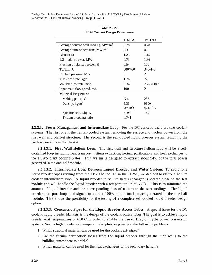
Design Description Document for the U.S. Dual Coolant Pb-17Li (DCLL) Test Blanket ModuleReport to the ITER Test Blanket Working Group (TBWG)
2-20 Rev. 3
Table 2.2.2-1
TBM Coolant Design Parameters
He/FW Pb-17Li
Average neutron wall loading, MW/m2 0.78 0.78
Average surface heat flux, MW/m2 0.3 0.3
Blanket M 1.23 1.15
1/2 module power, MW 0.73 1.36
Fraction of blanket power, % 0.54 100
Tin/Tout, oC 380/460 340/440
Coolant pressure, MPa 8 2
Mass flow rate, kg/s 1.76 72
Volume flow rate, m3/s 0.343 7.75 10-3
Input max. flow speed, m/s 100 2
Material Properties:
Melting point, oC Gas 235
Density, kg/m3 5.33
@440oC
9300
@400oC
Specific heat, J/kg-K 5193 189
Tritium breeding ratio 0.741
2.2.2.3. Power Management and Intermediate Loop. For the DC concept, there are two coolant
systems. The first one is the helium-cooled system removing the surface and nuclear power from the
first wall and blanket structure. The second is the self-cooled liquid breeder system removing the
nuclear power form the blanket.
2.2.2.3.1. First Wall Helium Loop. The first wall and structure helium loop will be a self-
contained loop including heat transport, tritium extraction, helium purification, and heat exchanger to
the TCWS plant cooling water. This system is designed to extract about 54% of the total power
generated in the one-half module.
2.2.2.3.2. Intermediate Loop Between Liquid Breeder and Water System. To avoid long
liquid breeder pipes running from the TBMs to the HX in the TCWS, we decided to utilize a helium
coolant intermediate loop. A liquid breeder to helium heat exchanger is located close to the test
module and will handle the liquid breeder with a temperature up to 650oC. This is to minimize the
amount of liquid breeder and the corresponding loss of tritium to the surroundings. The liquid
breeder transport loop is designed to extract 100% of the total power generated in the one-half
module. This allows the possibility for the testing of a complete self-cooled liquid breeder design
option.
2.2.2.3.3. Concentric Pipes for the Liquid Breeder Access Tubes. A special issue for the DC
coolant liquid breeder blankets is the design of the coolant access tubes. The goal is to achieve liquid
breeder exit temperatures of 650oC in order to enable the use of Brayton cycle power conversion
systems. Such a high breeder exit temperature implies, in principle, the following problems:
1. Which structural material can be used for the coolant exit pipes?
2. Are the tritium permeation losses from the liquid breeder through the tube walls to the
building atmosphere tolerable?
3. Which material can be used for the heat exchangers to the secondary helium?

Design Description Document for the U.S. Dual Coolant Pb-17Li (DCLL) Test Blanket ModuleReport to the ITER Test Blanket Working Group (TBWG)
Rev. 3 2-21
The use of concentric tubes with the “hot” exit flow in the inner tube and the “cold” inlet flow in
the annulus facilitates the points (1) and (2). The inner tube will always assume a temperature
between the hot and cold breeder temperature. This temperature can be influenced by the ratio
between the heat transfer coefficients in these two lines and, if required, by providing some thermal
insulation in the inner tube. (e.g., gap filled with stagnant fluid). By this means, a maximum
temperature of the tube wall below 550oC can be achieved even for a blanket exit temperature of
650oC.
Tritium permeating from the hot liquid breeder has no access to the environment but flows back
into the blanket with the “cold” breeder. The temperature of the outer tube can be made much lower,
reducing tritium permeation losses into the building atmosphere. Only the tube temperatures in the
heat exchange of a power plant will be close to the maximum breeder temperature, but this
temperature can significantly lowered in case of ITER TBMs.
An important point in designing concentric coolant access pipes is the possibility of using sliding
seals for the inner tube. Only the outer tube has to be cut/rewelded for an exchange, since small leaks
in the connection of the inner tube lead to a small bypass flow exclusively from the cold to the hot
side. Such sliding seals also facilitate the compensation of differential thermal expansions of the two
tubes and, as a result, the high temperature tube need only withstand a small pressure difference.
For these reasons we will apply concentric pipes wherever possible. This becomes another
demonstration of the test module technology development directly applicable to the DEMO design.
In the following sections, most of the illustrated liquid breeder piping is in concentric pipes.
Detail MHD and thermal analysis of the concentric piping design are presented in Section 3.2.1.
To avoid high temperature Pb-17Li compatibility problems at the external loop, a bypass Pb-17Li
circuit design is presented in Section 2.2.2.6, which is proposed for the first 10 years of ITER testing.
2.2.2.4. Ancillary System. This section covers the description of ancillary equipment of the Pb-17Li
and the first wall helium cooling loop.
2.2.2.4.1. Pb-17Li Systems
2.2.2.4.1.1. Overview of Flow Circuit Systems. See Fig. 2.2.2-1 for a working schematic of the
Pb-17Li flow systems and Table 2.2.2-2 for a tabulation of assumed and calculated characteristics of
the flow loop. Some points to note are listed below.
• The TBM is connected by concentric pipes that contain SiC flow channel inserts in the highmagnetic field region beginning roughly 2 m from the back of the TBM.
• A fairly low velocity in the magnetic field region is required to avoid fault conditions withlarge pressure drops. This velocity was picked at 2 m/s in a rather arbitrary fashion. This setsthe outer pipe diameter to be 0.16 m.
• Since the concentric tubes are attached at the bottom of the TBM, a bubble/pressure relief lineis required at the top of the TBM to allow filling/draining and venting of bubbles. This line isarbitrarily chosen to have outer diameter 0.025 m.
• Both the main concentric lines and the bubble/pressure relief line penetrate the VV andbioshield plugs back to the transporter region where the rest of the Pb-17Li systems arehoused.
Details of the Pb-17Li systems in the transporter and immediate vicinity are given below.

Design Description Document for the U.S. Dual Coolant Pb-17Li (DCLL) Test Blanket ModuleReport to the ITER Test Blanket Working Group (TBWG)
2-22 Rev. 3
Fig. 2.2.2-1. Pb-17Li system layout.
Table 2.2.2-2
Pb-17Li Flow System Specifications
TBM Base Case Pb-17Li
Average neutron wall loading, MW/m2 0.78
Average surface heat flux, MW/m2 0.3
Blanket M 1.006
One-half port power, MW 1.36
TBM width, m 0.645
TBM height, m 1.94
FW plasma facing area, m2 1.25
Pb-17Li Volume Summary:
TBM volume, m3 0.28
Supply pipe volume, m3 0.062
Pump/exp tank volume, m3 0.050
Heat exchanger volume, m3 0.027
Cold trap volume, m3 0.020
Tritium extraction column, m3 0.125

Design Description Document for the U.S. Dual Coolant Pb-17Li (DCLL) Test Blanket ModuleReport to the ITER Test Blanket Working Group (TBWG)
Rev. 3 2-23
Table 2.2.2-2 (Cont.)
Pb-17Li Thermal Hydraulics:
Pb-17Li Tin, oC 340
Pb-17Li Tout, oC 440
Pb-17Li pressure drop, MPa 2
Mass flow rate, kg/s 72.
Volume flow rate, m3/s 7.74 10-3
Pump efficiency, % 0.80
Pump electrical power, kW 19.35
Ave. Pb-17Li velocity in TBM, m/s 0.098
TBM Pb-17Li supply pipes Concentric
Flow speed, m/s 2
Connection to TBM Bottom
Pipe length, m 8
Flow area (each way), m2 0.004
Inner pipe o.d., m (incl. 5 mm FCI) 0.090
Inner pipe wall thickness, m 0.005
Outer pipe outer wall thickness, m 0.010
Outer pipe o.d., m (incl. 2 5 mm FCIs) 0.161
2.2.2.4.1.2. Pumping System. A similar pumping system as discussed in Ref. 2.2.2-1 is adopted
with an expansion vessel feeding into a free surface, single stage, centrifugal pump with a long,
vertical shaft. The shaft exits the pump housing above the level of the alloy Pb-17Li so seal
compatibility with the alloy is not crucial. Such pumps are commonly used for pumping high
temperature, heavy metal alloys and are both reliable and efficient. The pump electrical power is
approximately 20 kW assuming 80% efficiency.
The expansion vessel helps control the liquid metal level in the pump housing. The total Pb-17Li
volume is roughly assumed to be 0.05 m3 total in expansion tank and pump housing. The size of the
expansion tank is estimated as a vertically oriented cylinder 1 m in height and 0.25 m in diameter.
The size of the pump housing is identical, with an additional vertical height for the motor estimated at
0.5 m with diameter 0.4 m. Gas above the free surface level is controlled by a pressure control
system (details not yet available) and is circulated to remove tritium and volatile heavy metal
impurities (like Hg, see below).
The pump is located in the cold leg downstream of the heat exchanger.
2.2.2.4.2. Detritiation Unit. Current plans are to incorporate a detritiation unit for the Pb-17Li
itself similar in size and capacity to that planned by the HCLL team [2.2.2-2]. The detritiation unit is
a vertical bubble column with a helium purge that is connected to lines that lead to the glovebox in
the tritium plant. The size of the cylindrical unit is 0.4 m diam and 1.6 m high. It is located in the hot
leg, directly fed by the returning Pb-17Li from the TBM. It has a valved bypass system so not all
returning Pb-17Li needs to be fed through the detritiation unit. The bubble/pressure relief line from
the top of the TBM also feeds directly into this unit so that helium/tritium bubbles can be separated in
the same way. For the tritium extraction from the helium coolant, with the use of a Pd/Ag permeator

Design Description Document for the U.S. Dual Coolant Pb-17Li (DCLL) Test Blanket ModuleReport to the ITER Test Blanket Working Group (TBWG)
2-24 Rev. 3
located in the helium circulation loop, an extraction unit that is 2 1 1 m is assumed. In addition, a
pumping package of similar dimension will be needed.
2.2.2.4.3. Pb-17Li to Helium Heat Exchanger. A heat exchanger has been designed to allow
rejection of the full TBM thermal power from the Pb-17Li stream to a secondary helium cooling
system that leads to the TCWS building. This heat exchanger is roughly 0.25 m in diameter and 1.4
m in length with details of its design and analysis given in Table 2.2.2-3.
Table 2.2.2-3
Pb-17Li/He Heat Exchanger
ITER
Calculation By: D. P. Carosella
General Atomics
Calculation Sheet System ITER Test LoopTitle: Pb_17Li to Helium Heat Exchanger Design Max Size
Page No.: 36
Calculation No.: 1
IV. RESULTS:
Summary of Design Data for the Helium to Pb-17Li Heat Exchanger:
Metric English
Heat Duty: Qhex 1362kW� Qhex 4.647 106
� BTU hr1�
�
�
�
Effectiveness/NTU : eff 0.462� / NTU 0.801�
Design Uncertainty UNht 15%�
Pb-17Li Data :
Flow Rate: WPbLi 72.08kg sec1�
�
�
� WPbLi 158.91 lbsec-1
�
Inlet Temperature: TCPbLiin 440C� TFPbLiin 824F�
Outlet Temperature: TCPbLiout 340C� TFPbLiout 644F�
Pressure Drop: �PPbLi 0.0529MPa� �PPbLi 7.669psi�
Percent Pressure Drop:�PPbLi
PPbLimax5.29%�
Pumping Power PPPbLi 408.33watt� PPPbLi 0.548hp�
Helium Data:
Flow Rate: WHe 2.2kg sec1�
�
�
� WHe 4.8lbsec-1
�
Inlet Temperature: TCHein 180C� TFHein 356F�
Outlet Temperature: TCHeout 300C� TFHeout 572F�
Pressure Drop: �Ptot 0.075MPa� �Ptot 10.9psi�
Percent Pressure Drop�Ptot
PHe0.94%�
Pumping Power: PPHe 21.87kW� PPHe 29.33hp�
Maximum He Velocity in Tubes VelHeout 45.8m sec1�
�
�
� VelHeout 150.3ftsec-1
�
Velocity In Pipes: VelHemax 68.1m sec1�
�
�
� VelHemax 223.5ftsec-1
�
Velocity In The Inlet Orifice Velori 100.8m sec1�
�
�
� Velori 330.6 ftsec-1
�
ITER He-PbLi Hex.mcd 6/14/04 2:35 PM

Design Description Document for the U.S. Dual Coolant Pb-17Li (DCLL) Test Blanket ModuleReport to the ITER Test Blanket Working Group (TBWG)
Rev. 3 2-25
Table 2.2.2-3 (Cont.)
ITER
Calculation By: D. P. Carosella
General Atomics
Calculation Sheet System ITER Test LoopTitle: Pb_17Li to Helium Heat Exchanger Design Max Size
Page No.: 37
Calculation No.: 1
Summary of Design Data for Pb-17Li to Helium Heat Exchanger:
Metric English
Geometric Data
Overall DimensionsTotal Length TLtot 1.33m� TLtot 4.363 ft�
Shell Outside Diameter SOD 0.2527m� SOD 9.951in�
Heat Transfer Surface Area TubA 4.22m2
� TubA 45.45 ft2
�
Total Tube Length(Including Tube Sheets) TL 0.93m� TL 3.06 ft�
Heat Transfer Height: H 0.876m� H 2.87ft�
Inside Shell Diameter: Hexdia 0.2411m� Hexdia 9.494 in�
Head Height: b 0.06m� b 2.49in�
Gas Supply & Return Pipe Dia: diaHe 77.9272mm� diaHe 3.07in�
Pb-17Li Supply & Return Pipe Dia: diaPbLi 62.7126mm� diaPbLi 2.47 in�
Hot Tube Sheet Thickness TSThot 0.056m� TSThot 2.22 in�
Baffle Thickness: �baffle 6.35mm� �baffle 0.25 in�
Total Dry Weight: Wttot 95.8kg� Wttot 211.3 lb�
Tube Parameters:Number of Tubes Ntube 56�
Triangular Pitch Pitch 17.94mm� Pitch 0.7064 in�
Tube Inside Diameter: TubeID 12.7mm� TubeID 0.5 in�
Tube Outside Diameter: TubeOD 13.7mm� TubeOD 0.539in�
Tube Wall Thickness: �wall 0.5mm� �wall 0.02 in�
He Inlet Orifice Diameter: diaHeori 7.6mm� diaHeori 0.3 in�
Auxiliary Data
Total Shell Side Volume Volss 0.028m3
� Volss 0.991 ft3
�
Tube Side (He) Nusselt No. NuHe 251.7905�
Tube Side (He) Heat Transfer Coef. hHe 4414watt
m2K�
�
� hHe 777BTU
hr ft2
�
�
R�
�
�
Shell Side (Pb-17Li) Nusselt No. NuPbLi 10.6839�
Shell Side (Pb-17Li) HT Coef. hPbLi 8718watt
m2K�
�
� hPbLi 1535BTU
ft2R�
�
hr�
�
�
ITER He-PbLi Hex.mcd 6/14/04 2:35 PM

Design Description Document for the U.S. Dual Coolant Pb-17Li (DCLL) Test Blanket ModuleReport to the ITER Test Blanket Working Group (TBWG)
2-26 Rev. 3
The heat exchanger has the capacity to operate between two extreme modes. The base operating
mode has Pb-17Li flow rate and temperature rise as indicated in the base case summarized in Table
2.2.2-2. An alternate operating extreme is to have the Pb-17Li peak temperature much higher, at
around 650oC, with correspondingly lower Pb-17Li mass flow rate. This is to test the true dual
coolant feature of high outlet temperature. In both cases, the helium outlet of the HX should not be
higher than 400oC to keep permeation from helium pipes to the TCWS building manageable.
2.2.2.4.4. Liquid Breeder Purification System. Liquid metal purification systems are, in
general, required to control the oxygen content of the system, remove corrosion products, replenish
depleted lithium, and remove heavy metal isotopes [2.2.2-3]. Diffusion-type cold traps are effective
in removing many of these compounds including Polonium. Such a system should be used in the Pb-
17Li ancillary loop as a bypass on the cold leg. It is expected that activated mercury vapor may
accumulate in all cover gas areas [2.2.2-3]. A removal system for mercury has not yet been designed
but will be needed on the various cover gas systems controlling the dump tank, pump/expansion
vessel housing and detritiation unit. Close coordination on this issue with the HCLL group will be
pursued. For now, cold trap size should be estimated based on HCLL [2.2.2-1] and will require a
separate low-temperature coolant for the local heat exchanger.
2.2.2.5. Helium Cooling Subsystems
2.2.2.5.1. Subsystems Description. The helium cooling subsystems include two helium loops:
the primary first wall to helium heat transport loop (FW loop), and the liquid breeder to helium heat
transport loop (LB loop), which connects to the secondary helium to water loop. The helium cooling
subsystem, which interfaces with the secondary water loop is part of the ITER tokamak cooling water
system (TCWS). This system has been designed to supply cold water with a temperature of 35oC and
accept hot water with a temperature of 75oC. The pressure is moderate — lower than 1 MPa.
The helium cooling subsystems are to be housed in the TCWS vault approximately 70 m away
from the TBM (Figs. 2.2.2-2 and 2.2.2-3). The pipe routing is to be described in Section 2.2.3. The
piping must be placed 18 m horizontally and 14 m vertically within the shaft and again 60 m
horizontally plus 10 m between components. U-bend expansion loops are to be included, as required,
to mitigate thermal stresses due to the high temperature operating conditions. This results in a total
length for the hot leg and cold leg of about 100 m and 95 m, respectively, or similar length when
concentric pipes are used.
The envisaged space division among parties is as illustrated in Fig. 2.2.2-4. It is assumed that
there will be no crane available for vertical component handling. A total foot print size of 20 m2 will
be needed for the FW loop and LB loop helium cooling subsystems and approximately 5 m height in
the TCWS vault.
Figure 2.2.2-5 shows a flow diagram of the FW loop and interfaces to ancillary equipment. Figure
2.2.2-6 shows the flow diagram of the Pb-Li loops. Related main components for the FW loop and
one of the LB loops and their arrangement in the allocated space are illustrated in Section 2.2.3.
Besides the main components, several sets of tanks, a rack for pressure control equipment and a
cubicle for local electrical equipment have to be accommodated for the two loops. A more detailed
component description is given in Section 2.2.3.
The control panel for operation/monitoring of the cooling subsystem will be installed in the main
control room requiring a space of approximately 1 to 2 m2 for each one of the two loops. Small
electrical control equipment, like signal transducers, are planned to be placed inside the transfer cask,
where also some equipment of the tritium monitoring and extraction subsystem is housed.

Design Description Document for the U.S. Dual Coolant Pb-17Li (DCLL) Test Blanket ModuleReport to the ITER Test Blanket Working Group (TBWG)
Rev. 3 2-27
Fig. 2.2.2-2. Piping from TBM to TCWS building.
Fig. 2.2.2-3. Equatorial test port area with transporter.

Design Description Document for the U.S. Dual Coolant Pb-17Li (DCLL) Test Blanket ModuleReport to the ITER Test Blanket Working Group (TBWG)
2-28 Rev. 3
RF–He Relief Tank(01.5mX2.5m(h))
JA–H20(3mX7.4mX4.5(h))
EU–H20(3.3mX4.8mX4.5m(h))
JA–He(3.5mX7.4mX4.5m(h))
EU–He(2.5mX7.4mX3m(h))
JA–H20 Cooling Pipes
EU–H20 Cooling Pipes
JA–He Cooling Pipes
EU–He Cooling Pipes
16624.1
7400
Plan View of TBM Space (2001)Fig. 2.2.2-4. Arrangement of piping and TBM ancillary equipment areas.

Design Description Document for the U.S. Dual Coolant Pb-17Li (DCLL) Test Blanket ModuleReport to the ITER Test Blanket Working Group (TBWG)
Rev. 3 2-29
TRITIUMEXTRACTIONSUBSYSTEM
PRESSURECONTROL
SUBSYSTEM
SECONDARYCOOLING
SUBSYSTEM(ITER)
WATER @ 35C
WATER @ 43C
HELIUMPURIFICATIONSUBSYSTEM
TESTMODULE
SAFETYVALVES
FLOW METER
HELIUMCIRCULATOR
ELECTRICAL HEATER
T P
T
T
TP
T
P
HELIUM @ 8 MPa 440C
HELIUM @ 380C
HEAT EXCHANGER
TEMPERATURE TRANSDUCER
PRESSURE TRANSDUCER
Fig. 2.2.2-5. Helium cooling subsystem flow diagram.
Fig. 2.2.2-6. The Pb-17Li loop.

Design Description Document for the U.S. Dual Coolant Pb-17Li (DCLL) Test Blanket ModuleReport to the ITER Test Blanket Working Group (TBWG)
2-30 Rev. 3
2.2.2.5.2. Thermal Design Requirements. The helium cooling subsystem must be designed for
the operating conditions given in Table 2.2.2-4.
Table 2.2.2-4
Design Parameters of FW and LB Cooling Subsystems
First Wall
Helium/Water
Liquid Breeder,
Pb-17Li/Helium/Water
Inner port dimensions (width height), m m 1.31 0.78 1.31 0.78
Projected area of module facing the plasma, m m 1.27 0.74 1.27 0.74
Surface heat flux, MW/m2 0.3 0.3
Neutron wall loading, MW/m2 0.78 0.78
Total heat to be removed, MW 0.73 1.36
Temperature at module in/out, oC 380/460 340/440
Pressure, MPa 8 2
Number of circuits 1 2
Mass flow rate, kg/s 1.76 72
Secondary coolant Water Helium:water
Temperature at heat exchanger in/out, oC 35/43 180/300:35/70
Pressure, MPa <1 8:<1
Number of circuits 1 1
Mass flow rate, kg/s 17 (water) 2.2 (helium)
2.2.2.5.3. Layout of Heat Removal Loops
First Wall Loop. Main components of the FW helium cooling loop are (besides the test module)
a heat exchanger, circulator, electrical heater, control valves, and pipework. A flow diagram is shown
in Fig. 2.2.2-6. The primary loop is directly connected to the helium purification subsystem via small
pipes taking a small bypass flow. The primary function of the purification system is to remove
tritium that diffuses into the helium coolant. No other helium cleanup provisions are required, such
as a dust filter, since there are no sources of dust or other contaminants. Further interfaces are shown
in the flow diagram to the pressure control unit, which is needed for system evacuation, helium
supply, and protection against overpressure. Also shown is the minimum required instrumentation for
process control.
An overview of thermal-hydraulic data such as pressure loss, helium volume, and helium mass
inventory in the different components is displayed in Table 2.2.2-5. The overall pressure loss is 0.65
MPa at the extreme load conditions. During operation the total helium mass inventory in the loop
including the buffer tank and 10% margin amounts to 18.26 kg.
The primary loop components are described in Section 2.2.3 with a summary of the main
dimensions and masses involved, as far as thermal inertia is concerned, being displayed in Table
2.2.2-6. Heat losses are assessed in Section 2.2.2.5.8. An overview of component size is given in
Table 2.2.2-6.

Design Description Document for the U.S. Dual Coolant Pb-17Li (DCLL) Test Blanket ModuleReport to the ITER Test Blanket Working Group (TBWG)
Rev. 3 2-31
Table 2.2.2-5
First Wall Helium Cooling Loop Pressure Loss and
Helium Inventory Under Extreme Operating Conditions
Component Pressure Loss: MPa
Helium Volume
(m3)
Helium Mass
(kg)
Hot leg pipework 0.078 0.82 4.433
Cold leg pipework 0.068 0.78 4.599
Main pipe elbows 0.172 Incl. in pipes Incl. in pipes
Bypass to heat exchanger 0.029 0.0148 0.0873
Valves 0.166 0.0011 0.004
Heat exchanger 0.044 0.010 0.040
Circulator — 0.3 1.78
Electrical heater Bypassed 0.043 0.184
Buffer tank — 0.236 4.92
Test module 0.094 0.090 0.510
Totals 0.65 2.295 16.52(a)
(a)10% margin not shown.
Table 2.2.2-6
Enveloping Dimensions and Weights of the First Wall Helium Cooling Loop Components
(Dimensions Not Including Thermal Insulation)
Component
Number
per Loop
Diameter
(m)
Length
(m)
Weight
(kg)
Pipework (including bypass) 1 0.1023 180 2959
Heat exchanger 1 0.223 (o.d.) 0.63 45.7
Circulator 1 1.54 0.30 1979
Circulator motor 1 0.88 1.46 1670
Electrical heater 1 0.35 1.65 287
Helium storage tanks 9 0.4 2.6 4808
Helium dump tanks 4 0.4 2.6 2137
Buffer tank 1 0.4 2.6 534
Test module 1 2000
Total weight 16420
Pb-17Li Breeder Loop. As an option for the liquid breeder test module design, Fig. 2.2.2-6
shows the layout of the Pb-17Li breeder loop. It includes the intermediate breeder to helium loop.
Details of the Pb-17Li breeder circulation system are given in Section 2.2.2.5.1, and the bypass circuit
in Section 2.2.2.6. Main components of the Pb-17Li breeder helium cooling loop are identical to the
FW helium loop as described above.
2.2.2.5.4. TCWS Secondary Heat Removal Loop. As noted above, both FW and LB loops will
be connected to the secondary water cooled system. The secondary heat removal system is considered
to be part of the ITER cooling system. For the layout of the helium cooling subsystem, the secondary
heat removal system was assumed to provide a steady water flow with nominal inlet temperature of
35oC at the secondary side of the heat exchanger (see Section 5.3.2.1). For the FW cooling loop, Al

Design Description Document for the U.S. Dual Coolant Pb-17Li (DCLL) Test Blanket ModuleReport to the ITER Test Blanket Working Group (TBWG)
2-32 Rev. 3
piping is used to reduce the permeation of tritium into the water cooling system. At a water flow rate
of about 17 kg/s, the outlet temperature of water is at 43oC. This reduced temperature is selected to
maintain the Al piping at a maximum temperature of <160oC. Other means of reducing tritium
permeation will also be evaluated in the future. Some of the alternatives are Al sleeve/coating and
Alumina coating on SS tubes. These alternatives could allow higher water outlet temperature
operation.
For the LB loops, the intermediate loop helium is connected to the secondary water cooled
system. The outlet temperature will then vary according to the burn and dwell cycles between 70oC
and 35oC. Flow, pressure, and temperature monitoring are needed.
Different from that indicated in Figs. 2.2.2-5 and 2.2.2-6, the recommended piping from the
liquid-breeder/helium heat exchange to the helium/water exchanger is connected also by concentric
pipes to reduce thermal tritium losses. Al sleeve and/or Alumina coating applying to the external SS
pipes will also be assessed to further control the migration of tritium.
2.2.2.5.5. Maintenance/Remote Handling. Activation of cooling subsystem components
installed in the TCWS vault is expected to be generally low allowing controlled personnel access after
plant shutdown. In-service inspection such as examination of selected welds by different methods
(visual, eddy current, ultrasonic), inspection of circulator internals, functional tests of valves, leak
tightness of heat exchangers, etc., occur during test module change-out or during planned or
unplanned machine shutdown periods.
Remote handling is envisaged for connection and disconnection of the TBM. The procedure will
be standardized for all the test modules. For this purpose all the FW loop the attachment to the frame,
pipe size, elbow radii close to the TBM, tools, etc., are assumed to be standardized details developed
by ITER. At present, pipe sections of about 10.5 m length of the hot leg and cold leg each next to the
TBM with enlarged inner/outer diameters of 102.3/114.3 mm are foreseen. In the case of any defects
in heat exchangers or electrical heaters, replacement of the whole component may be more
appropriate than an in-situ repair.
TBM dismantling and transfer to the hot cells after testing will be performed with the aid of the
transfer cask, beginning after a shutdown period of at least one day. The decay heat of the whole
module is expected to be less than 1 kW at that time which would result in an adiabatic heating up of
the isolated TBM at a rate of about 2 K/h. It is assumed that during the dismantling procedure, the
vacuum vessel (VV) is vented and purged with dry air at 50oC. Under these conditions, it is expected
that the decay heat of the TBM can be dissipated to the surrounding without active cooling. Flooding
the transfer cask with dry air during the transfer period would likewise stabilize the TBM temperature
at a tolerable level. Thus, no active cooling of the TBM is needed during dismantling and transfer.
2.2.2.5.6. Assembly. All components of the cooling subsystems such as heat exchanger,
circulator, electrical heater, tanks, and valves will be pre-assembled at the factory and delivered to the
site as functional units. Connection of the components will be performed on site by conventional
means. They are mounted on the floor of the TCWS vault and require space for horizontal translation
by means of a lift truck with a load capacity of about 1000 kg. Field-welded joints will be subjected
to surface and/or volumetric inspection, followed by pressure and leak tests. Thermal insulation will
be installed after leak testing of the loop.
An exception is the installation of the test module. It will be brought into place by the aid of a
special transfer cask that is aligned with the test port. It is to be equipped with all tools needed for
positioning, aligning, locking, and connecting the module in the test port.
Design Description Document for the U.S. Dual Coolant Pb-17Li (DCLL) Test Blanket ModuleReport to the ITER Test Blanket Working Group (TBWG)
Rev. 3 2-33
2.2.2.5.7. Subsystem Startup, Control, and Shutdown. For the first startup or startup after a
major repair, the cooling subsystem is assumed to be clean and proof tested, components are at room
temperature and filled with air. Correspondingly, the ITER machine is supposed to be simultaneously
conditioned for startup. The following steps will then be taken with the cooling subsystem:
• Subsystem evacuation to <102 Pa within about 24 h
• Subsystem flooding with helium and pressurization to approx. 4.5 MPa at 25oC
• Heating to approximately 380oC within a few hours by a combination of the electrical heater
and circulator at full or reduced speed (see Section 2.2.3.3) with the HX bypassed
• Establishing secondary cooling water flow in the HX
• Establishing temperature control at desired baking temperature, (about 375oC at circulator
outlet) by controlling the flow through HX with bypass heater power still on
• Keeping subsystem stable for baking period
• Driving circulator to nominal speed
• Establishing temperature and pressure control at stand-by level: 380oC, 8±0.3 MPa at
circulator outlet, heater power off. Subsystem is then ready for operation.
During operation, the typical ITER load cycle is envisaged, i.e., pulse duration of 400 s and
repetition time of 1800 s with specified power ramp-up and ramp-down. The total power removed by
the FW and LB cooling loops thus varies between the maximum of about 1.4 MW (depending on the
actual load conditions at the TBM plus circulator power) and the minimum of the order of 0.14 MW,
the latter coming from circulator at reduced flow and from decay heat. This is a ratio of less than 10:1
as shown in Section 3.1.
Because of the given large mean temperature difference in the HX between the primary and
secondary side of the FW loop, the heat removed in the HX can most effectively be influenced by
primary helium flow control. Hence, the following preliminary subsystem control scheme is proposed
for pulsed operation, based on an initial thermodynamic analysis with consideration of the thermal
inertia of all components:
• The principal objective is to keep the test module FW inlet temperature at 380oC.
• The secondary cooling water inlet temperature is kept at 35oC.
• The circulator is operated at rated speed.
• The electrical heater is turned off.
• Flow partition through the HX and heater bypass is controlled as to maintain the inlet
temperature to the TBM as close as possible to 380oC.
If for some reason much longer dwell times or shutdown periods have to be bridged, decay heat
removal at reduced circulator speed, or even by natural convection, is envisaged.
2.2.2.5.8. Materials. All of the piping and components in the primary cooling subsystem have
been designed. Austenitic stainless steel (AISI 316L) in contact with a liquid breeder cannot be used
for temperatures ~> 420oC to 440oC due to corrosion. This means that for concentric pipes
arrangement, we can only use AISI 316L for the outer tube which is the only one to be cut/welded
during the exchange of a TBM. This would meet the ITER requirement for remote handling. The
inner tube will be designed with ferritic steel sliding seals and must be made of ferritic steel, which is
designed for operation up to ~550oC, allowing a maximum liquid breeder exit temperature of 650oC.
This interface temperature between ferritic steel and liquid breeder will have to be verified. As noted

Design Description Document for the U.S. Dual Coolant Pb-17Li (DCLL) Test Blanket ModuleReport to the ITER Test Blanket Working Group (TBWG)
2-34 Rev. 3
above, to reduce tritium permeation to the water system, Al tubes are proposed for the FW loop
helium/water heat exchanger. All of the piping and components will be equipped with 10 to 15 cm of
a mineral thermal insulation.
2.2.2.5.9. Interfaces to Other Equipment. Using the FW loop as an example, Table 2.2.2-7
summarizes the interfaces of helium cooling subsystem and gives estimates on space requirements for
installation and operation of the FW loop subsystem, based on the assumptions and layout described
in the foregoing. Also estimates on heat losses from the cooling circuit are added (Table 2.2.2-8).
The heat lost through the thermal insulation from the cooling circuit (piping and components, but
excluding the TBM proper) has been calculated. In the calculations, air at 30oC is assumed as ambient
atmosphere, stainless steel as structural material, and mineral wool as insulating material. Insulation
thickness is assumed to be 15 cm for all the piping and components. Table 2.2.2-8 shows main results
for the operating conditions specified in Table 2.2.2-4.
The heat losses amount to 15.29 kW. The insulation surface temperature runs up to 68oC. About
99.6% of the heat losses result from the piping, with more than 57.5% coming from the hot leg. In
addition, there is a total of 51.4 kW lost from the circulator motor. The circulator motor is not
insulated.
2.2.2.5.10. Tritium Extraction System. For the FW loop, in addition to the use of Al piping in
the heat exchanger for the reduction of the tritium into the water coolant system, tritium extraction
from the circulation helium is also envisioned. Description of this tritium extraction system is
presented in Section 2.3.
Table 2.2.2-7
Space Requirements and Supplies to DCLL Helium Cooling Subsystem
Space Requirements
• Foot total print area in TCWS for main components, ancillary equipment and all tanks is about 20 m2,
5 m high (Fig. 2.2.2.5-8 and Section 2.2.2.5.3)
• Space in transfer cask (parking cask) for measuring equipment rack, 0.5 0.5 2 m3 (Section 5.3.1)
• Space in main control room for subsystem control panel and operator, 12 m2 (Section 5.3.1)
• Space for piping from TBM to main components, about 195 m, up to 0.4 m diam with thermal insulation,
routing according to ITER drawings of TCWS vault (schematic shown in Figs. 2.2.2.5-3 and 2.2.2.5-4).
Supplies and Services
• Infrequent evacuation (to ~l00 Pa) of the main loop after maintenance, repair (Section 2.2.2.5.7).
• Secondary cooling water (up to 17 kg/s, 1 MPa, 35oC/43oC) to heat exchanger in TCWS, about 63 mm
diam piping.
• Electrical power for circulator up to about 300 kW (Section 2.2.3.2) and heater up to 170 kW (Section
2.2.3.3).
• Helium supply for main loop (approx. 2.52 m3/ 18.26 kg at operating conditions)
• TBM installation, connection/disconnection, and transfer to the hot cells by the transfer cask, i.e.,
cutting and welding of two main pipes 89 mm o.d. 6.0 mm wall, two purge gas pipes of approximately
25 2 mm
• Instrumentation and electrical cabling

Design Description Document for the U.S. Dual Coolant Pb-17Li (DCLL) Test Blanket ModuleReport to the ITER Test Blanket Working Group (TBWG)
Rev. 3 2-35
Table 2.2.2-8
Heat Losses from the First Wall Cooling Subsystem
for Different Operational Conditions
Nominal
Helium temp. inlet/outlet (oC) 380/460
Circuit heat losses other than the circulator motor (kW) 15.29
Peak insulation surface temp. (oC) 68
References for Section 2.2.2
[2.2.2-1] H. John et al., "DEMO-Relevant Test Blankets for NET/ITER," KFK 4908, 1991.
[2.2.2-2] Y. Poitevin et al. "WSG2-LiPb-LAFS-He Blanket Line Preparation Document on Integral-
TBM & Related Requirements," TBWG Meeting, Naka, Japan, March 2004.
[2.2.2-3] P. Norajitra et al., "Conceptual Design of the Dual-Coolant Blanket in the Frame of the EU
Power Plant Conceptual Study," TW2-TRP-PPCS12D9, FZKA 6780.
2.2.2.6. DCLL Bypass System. The main advantage of the DCLL concept in a power reactor
embodiment is its potential to achieve high Pb-17Li outlet temperature, desirable for achieving high
efficiency power conversion, while using the current generation of reduced activation ferritic steel as
the structural material and SiCf/SiC composites as essentially non-structural electrical and thermal
insulation. While there are several potential materials and systems for handling the high temperature
Pb-17Li flow in power reactor ancillary equipment (such as tritium extractor and heat exchangers)
outside the blanket itself, the development of these systems is not necessary for testing the main
concepts of the DCLL blanket during the early phases of ITER operation.
Low Temperature Operation. The Pb-17Li and primary helium coolant flow systems in the
ITER DCLL TBM are both designed to have flexibility in tuning the coolants mass flowrates and
inlet temperatures. This flexibility allows the entire TBM and TBM ancillary equipment to be
operated at low temperature so that the maximum Pb-17Li temperature is always below any ferritic
steel corrosion limit (~475oC), and the maximum ferritic steel temperature is below its strength limit
(~550oC). Even in such a conservative operating scenario, the coolants can be controlled such that
there still exists in the TBM a temperature difference between the Pb-17Li flow and the helium-
cooled ferritic steel walls, so that the thermal function of the insert can be tested, and issues of natural
convection resulting from temperature differences can still be studied. Even if SiCf/SiC itself is not
yet available as an insert material, a substitute insert made from ferritic-steel-clad alumina (already
produced in EU in the late 1980s) can be used to study the essential thermal behavior of the DCLL
concept in an ITER TBM.
The flexibility in the relative coolant flowrates and inlet temperatures will also allow a wide
matrix of blanket experiments to be performed, including exploration of the electrical insulation
function of the SiC inserts and tritium permeation effects at high Pb-17Li flowrates (nearly self-
cooled) to very low Pb-17Li flowrates (entirely separately-cooled). This redundant and overcapacity
design of the coolant flow systems is also a safety advantage, as even with total failure of the
SiCf/SiC insert, or a failure of one of the flow systems, a properly designed TBM should still be able
to operate safely until the next scheduled maintenance period.

Design Description Document for the U.S. Dual Coolant Pb-17Li (DCLL) Test Blanket ModuleReport to the ITER Test Blanket Working Group (TBWG)
2-36 Rev. 3
High Temperature Operation of the TBM Only. The Pb-17Li flowloop can also have a TBM
bypass capability that allows the reduction of Pb-17Li flowrate that goes to the TBM, resulting in an
increase Pb-17Li outlet temperature from the TBM (up to range of 650oC to 700oC if desired). But
this hot Pb-17Li returning from the TBM is mixed with the bypassed cold Pb-17Li at the bypass
section, resulting in only a warm stream going to the tritium extraction and heat exchanger systems.
In this way, the high temperature features of the TBM, especially the function of the SiCf/SiC as a
thermal insulator at high temperature, can be tested in the TBM without requiring high temperature
materials in the tritium extraction and heat exchanger systems. The bypass should be put as close to
the TBM as needed on the transporter, depending on whether the testing of high temperature access
piping with SiCf/SiC inserts is desired. Testing of high temperature ancillary systems can then be
deferred until later stages of ITER beyond the first 10 years after successful investigation of the high
temperature TBM operation.
Figure 2.2.2-7 shows a graphical representation of these ideas.
Fig. 2.2.2-7. DCLL TBM bypass loop schematic. DCLL TBM bypass loop can control PbLi/metaltemperature.
2.2.3. Component Description
The helium cooling subsystem is described in Section 2.2.2. This section provides design
descriptions of the subsystem components.
2.2.3.1. Heat Exchanger. A first layout has been performed for the FW loop HX assuming a
conventional tube and shell U-tube heat exchanger configuration with high pressure helium flowing
inside the tubes and low pressure water flowing outside (Table 2.2.3-1). The helium volume in the
HX will be 0.0096 m3 (0.0031 m3 in the tubes and 0.0065 m3 in the inlet and outlet plenums). The

Design Description Document for the U.S. Dual Coolant Pb-17Li (DCLL) Test Blanket ModuleReport to the ITER Test Blanket Working Group (TBWG)
Rev. 3 2-37
thermal-hydraulic data like flow velocity, pressure drops and heat transfer coefficients have been
taken from detailed MATHCAD models, Appendix B.
2.2.3.2. Circulator. Variable speed helium circulators will be installed in the cold leg of the helium
loops. An encapsulated type circulator with vertical shaft is envisaged where the type of bearings
(gas lubricated or magnetic) still has to be decided upon. As an example, the design specification for
the FW coolant loop circulator is as follows:
• Design temperature 440oC (maximum temperature __TBD__ oC short term).
• Rated pressure 8 MPa (plus approximately 10% margin for overpressure control).
• Mass flow rate 1.82 kg/s at a pumping head of 0.65 MPa at rated speed and at 380oC at the
outlet nozzle.
• Rated speed about TBD rpm, maximum speed TBD rpm, speed variation max/min of at least
TBD.
Table 2.2.3-1
Heat Exchanger Layout Data
Parameter Unit Extreme
Type of HX U-tube bundle
Number of HX 1
Tube size (outer/inner diam) mm 13.7/12.7
“U” Tube length (incl. plate) m 0.59
Number of “U” tubes per HX 41
Tube bundle diam length m 0.21 0.53
Overall HX diam length m 0.22 0.63
Heat to be removed per HX MW 0.57
Primary coolant Helium inside
Pressure MPa 8
Temperature in/out oC 380/460
Mass flow rate per HX kg/s 1.82
Flow velocity (maximum) m/s 65.1
Pressure drop (approx.) MPa 0.044
Heat transfer coeff. W/(m2K) 3974
Secondary coolant Water outside tubes
Pressure MPa 1
Temperature in/out oC 35/43
Mass flow rate per HX kg/s 16.99
Flow velocity (maximum) m/s 1.73
Heat transfer coeff. W/(m2K) 1.21 104
Under these conditions, the input electrical power of the drive motor would be about 295 kW
when assuming a combined circulator and motor efficiency of 0.68. The helium volume contained in
the circulator is estimated as 0.3 m3 and the overall dimensions of the circulator and drive unit are
expected to be 1.54 m diameter by 1.76 m in height.

Design Description Document for the U.S. Dual Coolant Pb-17Li (DCLL) Test Blanket ModuleReport to the ITER Test Blanket Working Group (TBWG)
2-38 Rev. 3
2.2.3.3. Electrical Heater. The electrical heater is needed for baking the test module first wall at
375oC and for heating the whole cooling subsystem, including the test module, to operating
temperatures after maintenance or repair periods. The heater will be positioned in a bypass to the HX,
assuming that the HX is isolated during heating periods and the circulator is operating at rated or
reduced speed. It has been estimated that an electrical power of 170 kW, together with a circulator
power of 80 kW, would enable the whole TBM system (including the circuit components involved
and heat losses, see Section 2.2.2.5.8) to be heated at a rate of about 200oC per hour in the case of
ideal uniform heating. The main dimensions of the heater are 0.21 m diameter by 1.25 m height,
approximately 18% of which is occupied by the heating rods. This yields a helium volume of 0.031
m3. The estimated pressure loss is small, ~500 Pa. The overall dimensions are assumed to be 0.35 m
diam (at flanges) by 1.65 m height (including the end dome foreseen for electrical terminals).
2.2.3.4. Pipework. For the main pipework of the FW loop, i.e., hot leg, cold leg and elbows, an
outer diameter of 114.3 mm and a wall thickness of 6.0 mm have been chosen. This results in flow
velocities of between 37.6 and 41.1 m/s for the cold and hot extreme operating conditions,
respectively. The pipe length is determined on the basis of the component arrangement in the TCWS
vault shown schematically in Figs. 2.2.2-3 and 2.2.2-4, considering two U-bends for thermal
expansion in the long horizontal pipe sections. Altogether, it yields a total length of the main
pipework of 195 m (95 m for the cold leg and 100 m for the hot leg). The total number of elbows
amounts to 44. Overall, the pipework contributes about 75% to the pressure losses in the loop.
The heater bypass line is supposed to be almost closed during burn times and open during dwell
times (see Section 2.2.2.5.7), in which the flow rate could be reduced compared to the rated mass
flow rate by slowing down the circulator. Also, the baking and heating procedure can be performed at
a reduced flow rate. Thus, the bypass to the HX would allow smaller dimensions than the main
pipework. Nevertheless, for simplicity, the same pipe size has been chosen for the FW loop design,
i.e., outer/inner diameter of 114.3 mm. Its length is only about 4 m.
2.2.3.5. Valves. The number of valves in the FW loop has been minimized to avoid inadvertent
closure, which would mean loss of heat sink, and to avoid additional pressure loss. Hence, only one
valve is installed before the HX in the main loop and another one in the bypass line before the
electrical heater. These two valves are needed for temperature control in normal cyclic operation and
must be position-controlled. Valve size corresponds to pipe dimensions (see Section 2.2.3.4). A
similar approach is required for the LB helium loop design.
2.2.3.6. Pressure Control Unit. This is a combination of equipment needed for evacuation of the
cooling subsystem, helium supply, pressure control, and overpressure protection. The components are
conventional and of relatively small size, except for the battery of tanks (see below). The pressure
control unit is essentially isolated from the main cooling loop during normal operation. However, in
case of a pressure drop caused by a small leak or by a loss of coolant accident, the buffer tank will
discharge into the main loop.
The evacuation unit is needed for the first startup as well as after repair of the main cooling loop.
It is assumed that a vacuum pipe line is provided for the ITER vacuum system. The pipe line has to be
reliably isolated from the loop after evacuation to avoid inadvertent interconnection of the loop with
other subsystems or pressurization of the vacuum system.
The helium supply and storage unit consists of a storage tank, buffer tank, compressor, and
pressure regulators. Except for the fresh helium supply and the decommissioning of the used helium,

Design Description Document for the U.S. Dual Coolant Pb-17Li (DCLL) Test Blanket ModuleReport to the ITER Test Blanket Working Group (TBWG)
Rev. 3 2-39
which are supposed to be provided by ITER, the supply and storage unit is designed to be self-
sufficient during the different TBM testing campaigns.
For the FW loop design, the storage tanks are therefore sized to handle the entire helium
inventory of the loop with 10% margin (excluding the inventory in the buffer tank). The total storage
tank inventory must be 2.269 m3. This can be achieved with nine tanks of 0.4 m diam and 2.6 m
long. With storage conditions of 14 MPa and 50oC, this results in a total mass storage of 47.3 kg.
During normal operation, the helium inventory including 10% margin and one buffer tank, is 18.26
kg. A multi-stage compressor and cooler will be needed to load the storage tank for emptying the
main loop. Similarly, the following parameters apply to the LB helium loop. The maximum helium
inventory (based on the LB case) is 55.9 kg. Hence, a maximum mass of 61.5 kg must be stored at
about 50oC, 14 MPa, resulting in a tank volume of 2.95 m3. This can be achieved by, e.g., twelve
tanks of 0.4 m diam, 2.6 m long.
Pressure control in the helium loop during nominal operation is achieved in the following way.
The storage tank is kept at low pressure (~l.5 MPa) so that the main loop can discharge to the storage
tank via the pressure regulator if the set point “pressure high” is reached. The buffer tank, on the other
hand, has to compensate for the loop pressure if the set point “pressure low” is reached. As it
discharges to the loop, a compressor from the storage tank will recharge it. A buffer tank volume of
10% of the FW loop volume is chosen, about 0.24 m3, at a maximum operating pressure of 14 MPa. If
one tank were to be used, its dimensions could be, e.g., 0.4/0.36 m outer/inner diameter by 2.6 m long
for the FW loop design. Because the helium operating temperature is lower for the LB loops, one
buffer tank will also be adequate for the secondary helium loop.
The overpressure protection of the cooling loop consists of two redundant safety valves or a
combination of one safety valve plus a burst disc. The safety valves discharge into a group of dump
tanks which are kept at controlled low pressure (near atmospheric) during normal operation. This
avoids releasing contaminated helium into the building and completely depressurizing the main loop
in case the valve would fail to close. The dump tanks are created in anticipation of the primary loop
inadvertently pressurizing to the nominal pressure (8 MPa) at room temperature causing the whole
subsystem to subsequently heat up to 380oC, the nominal operating inlet temperature. If, in this case,
the pressure regulator should fail to open, the safety valve would respond and balance the pressure
between the loop and the dump tanks. In order to limit the pressure to 8 MPa, a dump volume of
~50% of the loop volume (excluding the buffer tank volume), i.e., 1.03 m3, would be required This
can be achieved by, e.g., four tanks of 0.4 m diam by 2.6 m long. The lower helium temperature and
the higher helium inventory in the secondary loop result in the need for five dump tanks for the
secondary helium loop.
2.2.3.7. Procurement Packaging
To be provided.
2.2.4. Systems Design and Layout
2.2.4.1. General Space Allocations and Description for TBM. The equatorial ports allocated for
the test blanket modules have limited space and limited access through the port plugs. Space is also
limited outside the port area to accommodate all the ancillary equipment needed to service and run
the TBM. This space must be shared between the parties occupying the port. Furthermore, ITER
safety, remote handling and remote operations requirements must be met when designing the TBM
module and all of its support equipment. Figure 2.2.4-1 shows the standard test port arrangement

Design Description Document for the U.S. Dual Coolant Pb-17Li (DCLL) Test Blanket ModuleReport to the ITER Test Blanket Working Group (TBWG)
2-40 Rev. 3
where the TBM is connected to the transfer cask situated outside the Bio-Shield port opening. The
TBM module is mounted inside the shielding frame, which is water-cooled, providing the support of
the TBM and proper shielding behind the TBM as required by ITER. The TBM module along with
the shielding frame and the VV port plug forms one complete assembly called the VV port plug. The
port plug will be assembled and tested in the hot cell building prior to installation in the VV port
extension. A special transporter will be utilized to carry and install the port assembly into the VV
plug. Once the installation process is completed, the transporter will be moved out making room for
the transfer cask, which houses the supporting equipment for the TBM as shown in Figs. 2.2.4-2 and
2.2.4-3.
Fig. 2.2.4-1. Test port general arrangement.
Fig. 2.2.4-2. Breeder coolant loop.

Design Description Document for the U.S. Dual Coolant Pb-17Li (DCLL) Test Blanket ModuleReport to the ITER Test Blanket Working Group (TBWG)
Rev. 3 2-41
Fig. 2.2.4-3. Coolant loop details.
The TBM is connected to the transporter through series of pipes providing all the needed service
mainly for cooling and diagnostics. These pipes must penetrate two barriers as they are routed
between the transporter and the TBM. The U.S. TBM design relies on the two coolant loops and
purge lines to provide all the operational services needed. There are six pipes running between the
transporter and the TBM. One concentric pipe carrying the breeder Pb-17Li, with the hot liquid
running in the inner pipe, two He coolant lines for cooling the first-wall/structure and the breeder, a
drain pipe for draining the Pb-17Li liquid from the TBM and the VV plug assembly prior to removal
or in case of emergency, and finally a gaseous product purge line from the top of the TBM module.
2.2.4.2. Equatorial Test Port. TBM Module will be tested in pre-designated test ports on the
equatorial level. These test ports are similar in design to the other equatorial ports and could be used
interchangeably. A water cooled shield plug is designed to fill the port in case it was not used for
testing. However a similarly designed shield plug with provisions for the TBM will be used to test
the different blanket modules. The shield plug extends to form one assembly with the VV port
extension plug. This assembly is supported from the VV plug and is independent of the shielding
blanket.
2.2.4.2.1. Test Module Assembly. The TBM is mounted inside a specially designed shield plug
capable of holding two test modules with two different design concepts. As a result this assembly
must accommodate the two different modules and allow for services to support both modules. The
U.S. TBM module assembly shown in Fig. 2.2.4-4 includes the test module, the shield plug and the
VV port plug. The three major components will form on the complete assembly that will be mounted
inside the equatorial port extension. The shield plug is composed of two major segments. They are
the shielding frame which houses the TBM and the shielding module which is designed to fit directly
behind the TBM and will provide the necessary shielding based on ITER requirements. Both the
shielding frame and the shield plug are water cooled, with water pipes running from the VV port to
the TCWS building.

Design Description Document for the U.S. Dual Coolant Pb-17Li (DCLL) Test Blanket ModuleReport to the ITER Test Blanket Working Group (TBWG)
2-42 Rev. 3
Fig. 2.2.4-4. Test module assembly.
2.2.4.2.2. Pipe Penetration through VV Plug. As shown in Fig. 2.2.4-4, the test module
assembly consists of three major components, the test blanket module, the shielding frame and the
VV plug. The shielding frame is designed to be a housing support frame for the TBM and provide
the required shielding for the magnets and surrounding structure. All coolant and service pipes as
well as connectors such as power, control and instrumentation cables must run through the shielding
in order to connect to the TBM. In order to minimize streaming because of the penetrations through
the shielding, piping must be designed to prevent straight through access. This is especially critical
for larger size pipes, however further analysis is needed in order to determine the proper piping
penetration through the shielding block. Pipes connecting TBM to the VV plug are fixed on both
ends because the penetrations through the VV plug are rigid sealed connections. Thus expansion
loops will be used between the shielding and the VV plug to allow for thermal expansion.
The VV plug is designed as part of the test module assembly to provide the extended vacuum
boundary through the VV port extension. Therefore, all penetration through this plug must be sealed
to prevent any vacuum leaks. The TBM penetrations through the VV plug shown in Fig. 2.2.4-5 are
mainly for the He coolant line, the breeder fluid, and drain and purge lines. Table 2.2.4-1 provides a
summary of these penetrations. Space allocation on the plug surface must take into account any
additional area requirements for special penetration design. Isolation valves will be required on all
pipes outside the VV plug to seal and close all piping during transport, maintenance and remote
operations. These valves will also require certain clearances around them to avoid interference. More
details about the space requirements will be provided once the assembly procedure for the test module
assembly is developed and more details become available. This also applies to all cable connectors
running through the VV vessel plug (power, control and sensors). Additional area around each plug
will be needed to allow for a special sealed plug design.

Design Description Document for the U.S. Dual Coolant Pb-17Li (DCLL) Test Blanket ModuleReport to the ITER Test Blanket Working Group (TBWG)
Rev. 3 2-43
Fig. 2.2.4-5. Vacuum vessel plug.
Table 2.2.4-1
Vacuum Vessel Plug Penetration Summary
Description
Size
(mm)
Number
of Pipes
Approx.
Penetration Size
(mm) Tin/out
Concentric Pipe penetration breeder
fluid (Pb-17Li)
Inner pipe o.d. 90mm
Outer pipe o.d. 160 1 190
Primary FW coolant lines, He o.d. 88.9 2 100
Breeder fluid drain line o.d. 88.9 1 100
Bubbler/pressure relief line o.d. 46 1 65 NA
Power/control cable connection 75 2 110 NA
Instrumentation cable connections 50 2 75
2.2.4.2.3. Remote Maintenance and Handling. The TBM assembly including the shielding
plug and the VV plug are preassembled in the hot cell area and transported to the equatorial ports
using a special transporter design for equipment handling and insertion into the VV port. The
transporter will be positioned in front of the bio-shield port opening for test module assembly
installation. Once the Bio-Shield plug is removed and the VV plug with the shielding assembly is
taken out then the remote handling equipment inside the transporter will be used to insert and secure
the TBM plug assembly into the VV port extension. The next step in this process is to make all the
necessary piping connections between the module assembly and the transported. More details of the
step-by-step process will be provided later.
2.2.4.3. Pass-Through Design. Pipe penetrations are designed to facilitate the pipe runs between the
VV plug and the transfer cask outside the bio-shield door. Procedures for installation and removal of
the test blanket plug assembly are carefully planned to utilize both hands on and remote operations.
Hands-on maintenance operations are permitted to the point when the VV plug seal is opened. At this

Design Description Document for the U.S. Dual Coolant Pb-17Li (DCLL) Test Blanket ModuleReport to the ITER Test Blanket Working Group (TBWG)
2-44 Rev. 3
stage, remote operations are required. However, hands-on operation has limitation on the amount of
time maintenance personnel are exposed after the removal of the bio-shield plug.
In order to facilitate the removal of the test blanket assembly, a hands-on cutting operation using
the internal boring tool will be used to cut the pipe on the inboard side of the bio-shield plug. After
all connections are removed, the bio-shield plug will be removed thus exposing the pipes and the VV
plug. The concentric pipe assembly used to transport the breeder fluid will require a special
procedure for separating the inner pipe and then cutting the outer the pipe. Once all connections are
removed and the bio-shield is removed, additional cuts will be performed to remove all piping and
connections in preparation for the removal of the test blanket assembly. Detailed procedures will
later be developed based on final configuration designs.
Because of the use of liquid metal, the use of expansion loops to accommodate the thermal
expansion between the VV and the bio-shield plug may be limited due to drainage issues. This will
require the expansion joints at the bio-shield plug such as bellows to allow the pipe to penetrate the
VV plug without causing any failures. Final design recommendation on the use of expansion loops or
bellows will be considered later, however pipe penetrations through the bio-shield plug must be
spaced to accommodate these possible design requirements.
2.2.4.4. Bio-shield Plug. The Bio-shield plug is a 2-m thick concrete plug designed to provide
shielding of the equipment in the equatorial test port area during operation. The plug is composed of
block designed to accommodate the pipe penetrations as they are connected to the transporter just out
side the bio-shield. Operations outside the bio-shield are considered hands on, thus facilitating the
installation and separation of the transporter from the related services during maintenance operations.
2.2.4.5. Space Allocation of Equatorial Port Area. The equatorial port area just outside the bio-
shield is used as a staging area for a multitude of operations in conjunction with the installation,
removal and operation of the TBM. The area is large enough to accommodate a container 7 m long,
2.65 m high and 2.6 m wide. Longer containers could be used up to 7.6 m long in case confinement is
not required for the particular operation. A series of special design transporter will be utilized during
the course of the test blanket module operation. Transporters will be used to remove and install the
bio-shield plug. Installing and removing the test module assembly will require a special transporter
with heavy lift equipment built into it and designed to perform remote operation for the test module
insertion. During operation the equipment transporter shown in Fig. 2.2.4-6 will be parked in this area
and will contain all the primary coolant loops and tritium extraction system as well as all
instrumentation and control systems to monitor the test module status and collect the test data.
Table 2.2.4-2 is a summary of the equipment installed in the transporter. The space inside the
transporter will be used to house the all the equipment needed for both test modules that are being
tested in the corresponding port. This table lists only the equipment needed for the U.S. test module.
The transporter will be stationed out side the bio-shield and has various connections to the test
modules for the coolant lines, purge and drain lines as well all power control and instrumentation.
Table 2.2.4-3 lists a penetration summary for the transporter. All lines connecting the transporter to
the test module assembly penetrate the transporter through the front side while all lines going between
the test port area and the TCWS area penetrate the transporter through the side as shown in Fig. 2.2.4-
7. Prior to moving the transporter, these connections will be removed. Internal power inside the
transporter may have to be supplied to provide the trace heaters with power during transit between the
test port area and the hot cell area. This is needed to prevent any freezing of the or the liquid metal if
the system is already filled.
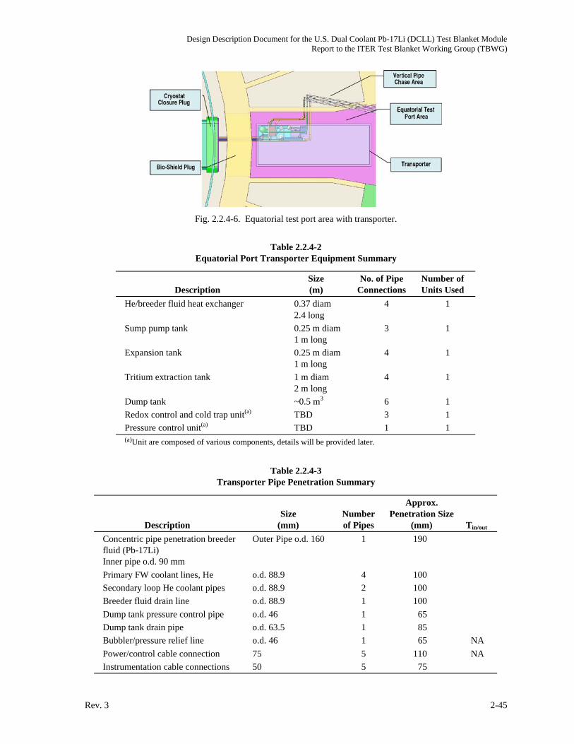
Design Description Document for the U.S. Dual Coolant Pb-17Li (DCLL) Test Blanket ModuleReport to the ITER Test Blanket Working Group (TBWG)
Rev. 3 2-45
Fig. 2.2.4-6. Equatorial test port area with transporter.
Table 2.2.4-2
Equatorial Port Transporter Equipment Summary
Description
Size
(m)
No. of Pipe
Connections
Number of
Units Used
He/breeder fluid heat exchanger 0.37 diam
2.4 long
4 1
Sump pump tank 0.25 m diam
1 m long
3 1
Expansion tank 0.25 m diam
1 m long
4 1
Tritium extraction tank 1 m diam
2 m long
4 1
Dump tank ~0.5 m3 6 1
Redox control and cold trap unit(a) TBD 3 1
Pressure control unit(a) TBD 1 1
(a)Unit are composed of various components, details will be provided later.
Table 2.2.4-3
Transporter Pipe Penetration Summary
Description
Size
(mm)
Number
of Pipes
Approx.
Penetration Size
(mm) Tin/out
Concentric pipe penetration breeder
fluid (Pb-17Li)
Inner pipe o.d. 90 mm
Outer Pipe o.d. 160 1 190
Primary FW coolant lines, He o.d. 88.9 4 100
Secondary loop He coolant pipes o.d. 88.9 2 100
Breeder fluid drain line o.d. 88.9 1 100
Dump tank pressure control pipe o.d. 46 1 65
Dump tank drain pipe o.d. 63.5 1 85
Bubbler/pressure relief line o.d. 46 1 65 NA
Power/control cable connection 75 5 110 NA
Instrumentation cable connections 50 5 75

Design Description Document for the U.S. Dual Coolant Pb-17Li (DCLL) Test Blanket ModuleReport to the ITER Test Blanket Working Group (TBWG)
2-46 Rev. 3
Fig. 2.2.4-7. Transporter side wall pipe penetrations to vertical pipe chase area.
2.2.4.6. Vertical Pipe Chase Area. All pipes and other connectors running between the test port
area and the TCWS will be routed through the vertical pipe chase area. Figure 2.2.4-8 shows the
pipes penetrations at the equatorial port level.
Fig. 2.2.4-8. Pipe penetration into vertical pipe chase area.
There are a total of six pipes running from the transporter to the TCWS area through the vertical
pipe chase. The vertical run between the equatorial port level and the TCWS level is approximately
15 m long. The pipe bundle will have appropriate vertical supports allowing for thermal expansion.
Expansion loops may not be an option through the pipe chase area simply because of space
limitations. In addition to all the TBM piping, the pipe chase area will have the blanket coolant lines
and other services running through it. As a result thermal expansion of this pipe run will be
accommodated in the TCWS area.
Figure 2.2.4-9 shows the pipe run through the vertical pipe chase area as it reaches the TCWS
area.
As the pipes reach the upper TCWS area they turn 90 deg toward the west wall in a horizontal run
approximately 5 m long. Figure 2.2.4-10 shows the pipe run trough the TCWS area. The pipe run is
approximately 28 m long and will have incorporate expansion loops to allow for thermal expansion.

Design Description Document for the U.S. Dual Coolant Pb-17Li (DCLL) Test Blanket ModuleReport to the ITER Test Blanket Working Group (TBWG)
Rev. 3 2-47
Fig. 2.2.4-9. Equatorial port and pipe chase area.
Fig. 2.2.4-10. TBM pipe run through TCWS area.
2.2.4.7. TCWS Building Layout and Available Space. A space of 16.6 7.3 m with a clear height
of 5 m is assigned in the south end of the TCWS building for all TBM cooling system. This space is
shared with all the parties to house the corresponding cooling systems. The U.S. TBM design
requires a primary and secondary He coolant loops that are located in this area. Table 2.2.4-4 lists a
summary of the equipment to be used. The two loops will share some equipment such as the pressure
control system and the tritium processing system.
The coolant lines will be connected directly to He-Water heat exchangers. The water pipes from
the heat exchanger will be routed to the ITER heat removal system. Interface for this area will be
defined in more details at a later time. He circulators located in the TCWS area will circulate the He
back into test module assembly. Figure 2.2.4-11 shows the general arrangement of the cooling
equipment located in the TCWS area.

Design Description Document for the U.S. Dual Coolant Pb-17Li (DCLL) Test Blanket ModuleReport to the ITER Test Blanket Working Group (TBWG)
2-48 Rev. 3
Table 2.2.4-4
Primary and Secondary Coolant Loops Equipment Summary
Description
Size
(m)
No. of Pipe
Connections
Number of
Units Used
He/water heat exchanger, primary and
secondary loops
0.22 diam
0.63 long
4 2
He heating unit 0.35 diam
1.65 long
2 2
He circulator 1.8 diam
2.4 long
2 2
Pressure control sub system(a) TBD 2 2
Tritium extraction sub-system(a) TBD 2 1
Flow meter TBD 2 4
(a)Subsystems include various components, details will be provided later.
Fig. 2.2.4-11. U.S. TBM primary and secondary coolant loops in TCWS.
The tritium processing and extraction system for both primary and secondary coolant loops. are
also located in the TCWS area. Based on the current design and the equipment layout the total area
requirements for the FW/structure and breeder helium cooling systems in the TCWS building should
not exceed 20 m2 for the U.S. TBM design. This requirement may be revised based on additional
design details and changes. Figure 2.2.4-12 shows a plan view of the equipment layout in the TCWS
building. The layout currently occupies an area 6.7 m long by 3 m wide.
Services running from the TCWS area to the general ITER plant include the water coolant for the
primary and secondary loops and the He purification bypass lines. The final pipe runs for these lines
will be determined later based on more design details.
2.2.5. Procurement Package
To be provided.
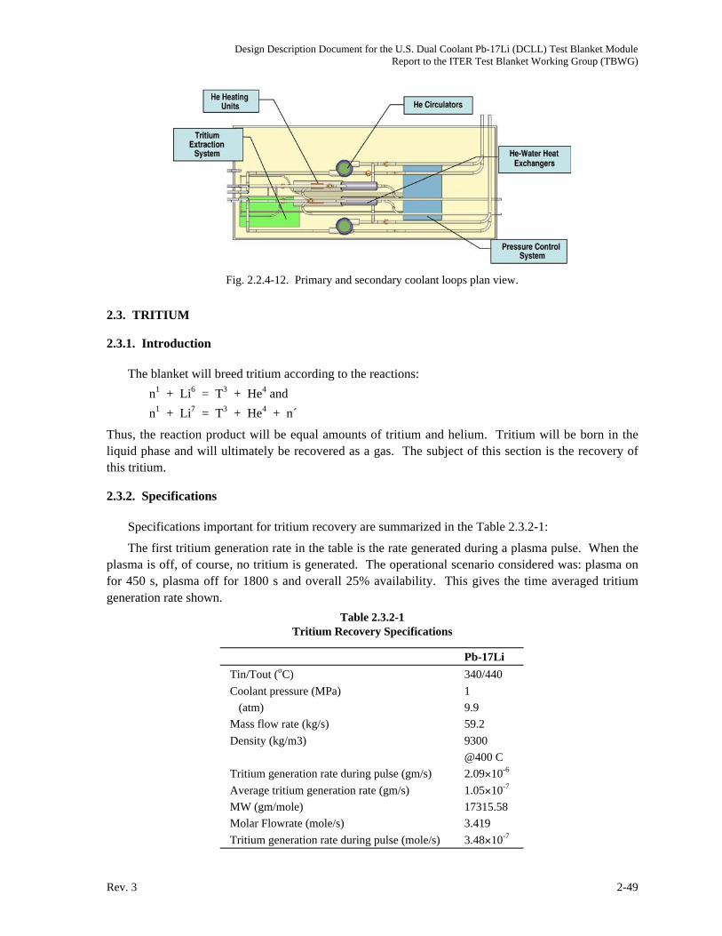
Design Description Document for the U.S. Dual Coolant Pb-17Li (DCLL) Test Blanket ModuleReport to the ITER Test Blanket Working Group (TBWG)
Rev. 3 2-49
Fig. 2.2.4-12. Primary and secondary coolant loops plan view.
2.3. TRITIUM
2.3.1. Introduction
The blanket will breed tritium according to the reactions:
n1 + Li6 = T3 + He4 and
n1 + Li7 = T3 + He4 + n´
Thus, the reaction product will be equal amounts of tritium and helium. Tritium will be born in the
liquid phase and will ultimately be recovered as a gas. The subject of this section is the recovery of
this tritium.
2.3.2. Specifications
Specifications important for tritium recovery are summarized in the Table 2.3.2-1:
The first tritium generation rate in the table is the rate generated during a plasma pulse. When the
plasma is off, of course, no tritium is generated. The operational scenario considered was: plasma on
for 450 s, plasma off for 1800 s and overall 25% availability. This gives the time averaged tritium
generation rate shown.
Table 2.3.2-1
Tritium Recovery Specifications
Pb-17Li
Tin/Tout (oC) 340/440
Coolant pressure (MPa) 1
(atm) 9.9
Mass flow rate (kg/s) 59.2
Density (kg/m3) 9300
@400 C
Tritium generation rate during pulse (gm/s) 2.09 10-6
Average tritium generation rate (gm/s) 1.05 10-7
MW (gm/mole) 17315.58
Molar Flowrate (mole/s) 3.419
Tritium generation rate during pulse (mole/s) 3.48 10-7

Design Description Document for the U.S. Dual Coolant Pb-17Li (DCLL) Test Blanket ModuleReport to the ITER Test Blanket Working Group (TBWG)
2-50 Rev. 3
Table 2.3.2-1 (Cont.)
Pb-17Li
Loop volume (m3) 0.5
Heat exchanger area (m2)
Breeder to He 3.93
He to water 4.45
Heat exchanger tube thickness (mm)
Breeder to He
He to water 0.266
Solubility 1.00 10-8
Units at. fr./Pa0.5
2.3.3. Tritium Extraction Description
A functional flow diagram showing the major elements of tritium generation and extraction is
given in the Fig. 2.3.3-1:
T2/BreederSeparator
HeatExchanger
Breeder, T2 , He
Breeder
T2Breeding
He, T2
Breeder, T2
T2 , He
He
Permeator
T2
He, T2
He
Permeator
To Tritium Plant
T2
To Tritium Plant
Dual CoolantBlanket
HeatExchanger
He
He
Fig. 2.3.3-1. Functional flow diagram of the tritium system.
The two side-by-side vessels represent the dual coolant blanket. The left-hand vessel is an ideal-
ized representation of helium portion of the blanket and the right-hand vessel is the Pb-17Li portion
of the blanket. It is only in the latter vessel that tritium is bred and that vessel is labeled accordingly.
Pb-17Li leaves the blanket. This stream consists of Pb-17Li, tritium and helium. This stream is
sent to the vessel labeled T2/Breeder Separator. This vessel is a relatively simple tank which includes
the capability to sparge helium bubbles into the bottom of the tank. This vessel is a gas-liquid

Design Description Document for the U.S. Dual Coolant Pb-17Li (DCLL) Test Blanket ModuleReport to the ITER Test Blanket Working Group (TBWG)
Rev. 3 2-51
counter-current contactor. The tritium is removed from the Pb-17Li as it moves from the liquid Pb-
17Li into the gaseous helium. The helium/tritium mixture leaves the separator near the top, and this
stream is sent to the Tritium Plant.
The Pb-17Li exits the separator at the bottom. This stream is sent to a heat exchanger. The heat
exchanger is a gas-liquid exchanger where Pb-17Li is the liquid and helium is the gas. This is a high
surface area device intended to transfer heat from the Pb-17Li to the helium. Because of the high
surface area and the fact that tritium is permeable in the heat exchanger tubes, tritium will be
transferred to the helium coolant. Pb-17Li will be sent from the heat exchanger back to the blanket,
thus completing the Pb-17Li circulation loop.
Tritium in the heat exchanger helium will need to be recovered. Shown at the bottom right of the
figure is a permeator. This is to be a Pd/Ag permeator will a vacuum on the permeate side [2.3-1,
2.3-2]. In this manner tritium in the helium will move to the permeate side, and this stream of tritium
(and any other hydrogen isotopes) will be sent to the Tritium Plant.
It is expected that due to permeation, tritium will also migrate into the blanket helium. Shown on
Fig. 2.3.1-1 is another vacuum permeator to recover this tritium (using the same concept as above).
As an alternative to the vacuum permeators, an oxidation/adsorption system could be used, but in
this case the tritium will be converted to the T2O form.
2.3.4. Equipment Size
2.3.4.1. Tritium Extraction from Pb-17Li. Exact sizing of this equipment is not possible at this
point, but it is expected that a tank which holds 100 l of active volume should be sufficient (50 l of
headspace and 50 l for liquid). Insulation and the like would add another 50% to the volume, so the
tank would occupy 150 l of space. The tank would likely be mounted vertically. This would be the
preferred configuration for bubble column operation. If, however, no bubbles were used, horizontal
mounting would be preferred.
2.3.4.2. Tritium Extraction from Helium Coolant. A low-pressure permeator system consists of a
permeator and a high vacuum pumping system. The latter includes a turbo pump and a backing
pump. The permeator will be approximately 2 m long 1 m in diameter (cylinder). The pumping
package will occupy a space of about 2 1 1 m (rectangle).
2.3.4.3. Tritium Extraction from First Wall Helium. This can be performed with a system
identical to the Helium Coolant system (immediately above).
2.3.5. Alternate Tritium Extraction Scheme
The analysis for the bubbler-based tritium extraction scheme (presented later in this document)
shows that only a modest fraction of the tritium will likely be recovered in the bubbler. This
prompted consideration of the possibility of using a vacuum permeator for removal of tritium from
the Pb-17Li. This device which would replace the bubbler would be similar in many respects to a
shell and tube heat exchanger. The tritium-containing Pb-17Li would flow on the inside of the tube
bundle. But, instead of a cooling gas in the shell, a vacuum would be maintained in the shell. This
would promote permeation of tritium from the Pb-17Li to the vacuum. An initial analysis of the
permeation properties of this device (presented later in this document) shows that such a device could
deliver attractive performance. However, such a device has never been constructed and tested. And a
multitude of questions remain open as to whether or not such a device could be successfully operated.

Design Description Document for the U.S. Dual Coolant Pb-17Li (DCLL) Test Blanket ModuleReport to the ITER Test Blanket Working Group (TBWG)
2-52 Rev. 3
Thus, this device cannot presently be recommended for practical use, but, due to its potentially
attractive properties, it should be seriously considered for research and development.
References for Section 2.3
[2.3-1] Willms, R. Scott, Pamela R. Arzu, Kevin G. Honnell and Stephen A. Birdsell; "Initial
Testing of a Low Pressure Permeator for Tritium Processing," Fusion Engin. and Design,
49-50 (2000) 963.
[2.3-2] Willms, R.S., D. Tuggle, S. Birdsell, J. Parkinson, B. Price, D. Lohmeir; “Comparison of
Methods for Separating Small Quantities of Hydrogen Isotopes from an Inert Gas”; Proc.
17th IEEE/NPSS Symp. on Fusion Energy, San Diego, California, 1997 (Institute of
Electrical and Electronics Engineers, Inc. 1998) Vol. 1, p. 304.

Design Description Document for the U.S. Dual Coolant Pb-17Li (DCLL) Test Blanket ModuleReport to the ITER Test Blanket Working Group (TBWG)
Rev. 3 3-1
3. PERFORMANCE ANALYSIS
3.1. NUCLEAR ANALYSIS
3.1.1. Neutronics Calculation Procedure
Neutronics calculations were performed to determine the relevant nuclear performance
parameters for the DCLL TBM. These include tritium breeding, nuclear heating, radiation damage,
and shielding requirements. The neutron wall loading at the TBM is 0.78 MW/m2. The front surface
of the module is 64.5 cm wide and 194 cm high resulting in a total surface area of 1.25 m2. A 2-mm
thick beryllium layer is utilized as a plasma facing component (PFC) material on the ferritic steel first
wall (FW). The lithium in the lithium lead (Li17Pb83) eutectic is enriched to 90% Li-6. 5-mm thick
SiC flow channel inserts (FCI) are used at the inside walls of all Pb-17Li flow channels. The ferritic
steel (FS) alloy F82H is used for structural material [3.1-1].
In this phase of the analysis, one-dimensional (1-D) neutronics calculations were performed to
allow for frequent iteration in the early stage of the TBM design process. The ONEDANT module of
the DANTSYS 3.0 discrete ordinates particle transport code system [3.1-2] was used to perform the
calculations utilizing the FENDL-2 nuclear data library [3.1-3]. Both the inboard (IB) and outboard
(OB) regions were modeled simultaneously to account for the toroidal effects. The IB shielding
blanket is modeled with its radial configuration including the Be tiles and Cu heat sink.
The radial configuration of the DCLL TBM is modeled in the OB region. Material composition in
the radial layers of the TBM was determined to account for the detailed configuration and material
variation in both the toroidal and poloidal directions based on the current CAD drawings of the TBM
as shown in Fig. 3.1-1. Table 3.1-1 gives the radial build and composition used in the calculations.
The total radial depth of the TBM is 41.3 cm (excluding the 2 mm Be PFC). The TBM inlet/outlet
piping zone behind the TBM is 30 cm thick with 5% FS, 1% Pb-17Li (LL), 0.2% SiC, 10% He, and
83.8% void. A separate 316SS/H2O shield plug is used behind the TBM piping zone. The shield is
assumed to consist of 75% 316SS and 25% H2O. A 1.2 m thick shield plug was used in the initial
calculation.
Fig. 3.1-1. Internal structure of the DCLL TBM.

Design Description Document for the U.S. Dual Coolant Pb-17Li (DCLL) Test Blanket ModuleReport to the ITER Test Blanket Working Group (TBWG)
3-2 Rev. 3
Table 3.1-1
Radial Build and Composition Used in the Neutronics Calculations
Zone Description
Thick
(mm)
Be
(%)
FS
(%)
LL
(%)
SiC
(%)
He
(%)
1 PFC Layer 2 100 0 0 0 0
2 Front wall of FW 4 0 100 0 0 0
3 FW cooling channel 20 0 17 0 0 83
4 Back wall of FW 4 0 100 0 0 0
5 SiC insert 1 5 0 8.1 0 80 11.9
6 Front breeding channel 70 0 8.1 75.7 4.3 11.9
7 SiC insert 2 5 0 8.1 6.1 73.9 11.9
8 Flow divider plate 15 0 54.8 6.1 0.4 38.7
9 SiC insert 3 5 0 8.5 6.1 73.3 12.1
10 Back breeding channel 110 0 8.5 74.7 4.7 12.1
15 SiC insert 4 5 0 8.5 1 78.4 12.1
16 Back wall 170 0 62.8 1 0.2 36
Total 415
Once the DCLL TBM design is finalized a detailed 3-D model will be developed for the TBM.
This TBM model will be integrated with the full ITER basic device 3-D model. 3-D neutronics with
the detailed integrated model will be performed using the MCNP, version 5 Monte Carlo code [3.1-4]
to update the neutronics parameters provided here from the 1-D model.
References for Section 3.1
[3.1-1] R. Klueh et al., "Impurity effects on reduced-activation ferritic steels developed for fusion
applications," J. Nucl. Mater. 353-359, 280 (2000).
[3.1-2] R.E. Alcouffe et al., "DANTSYS 3.0, A Diffusion Accelerated Neutral Particle Transport
Code System," LA-12969-M, Los Alamos National Laboratory (June 1995).
[3.1-3] M. Herman and H. Wienke, "FENDL/MG-2.0 and FENDL/MC-2.0, The Processed Cross-
Section Libraries For Neutron-Photon Transport Calculations," Report IAEA-NDS-176,
Rev. 3, International Atomic Energy Agency (October 1998).
[3.1-4] X-5 Monte Carlo Team, "MCNP-A General Monte Carlo N-Particle Transport Code,
Version 5-Volume II: Users Guide," LA-CP-03-0245, Los Alamos National Laboratory
(April 2003).
3.1.2. Tritium Breeding
The calculated local tritium breeding ratio (TBR) in the DCLL TBM is only 0.741 because of the
relatively small thickness used, which is limited by the amount of Pb-17Li that we can use due to
safety reason. During a D-T pulse with 500 MW fusion power, tritium is produced in the DCLL TBM
at the rate of 3.2x10¹⁷ atoms/s (1.59x10⁻⁶ g/s). Figure 3.1-2 shows the radial variation of tritium
production rate in the Pb-17Li during the 500 MW D-T pulse. The peak tritium production rate in Pb-
17Li is 2.94x10⁻⁸ kg/m3s. For a pulse with 400 s flat top preceded by 100 s linear ramp up to full
power and followed by 100 s linear ramp down the total tritium generation in the TBM is 7.97x10⁻⁴

Design Description Document for the U.S. Dual Coolant Pb-17Li (DCLL) Test Blanket ModuleReport to the ITER Test Blanket Working Group (TBWG)
Rev. 3 3-3
g/pulse. For the planned 3000 pulses per year the annual tritium production in the TBM is 2.4 g/year.
The tritium inventory in the TBM at any time will be much smaller since tritium will be continuously
extracted from the Pb-17Li. Tritium production rate in the Be PFC is only 2.2x10⁻⁹ g/s during the 500
MW D-T pulse with total annual generation of 3.3x10⁻³ g/year representing only 0.14% of the total
tritium production in the TBM.
0.0×1000
5.0×10⁻⁹
1.0×10⁻⁸
1.5×10⁻⁸
2.0×10⁻⁸
2.5×10⁻⁸
3.0×10⁻⁸
105 15 20 25 30Radial Distance from FW (cm)
Radial distribution of tritium productionin LiPb breeder
Neutron wall loading 0.78 MW/m2
DCLL TBMLiPb/He/FS
90% Li-6
Triti
um P
rodu
ctio
n Ra
te (k
g/m
3 .s)
Back channelFront
channel
Fig. 3.1-2. Radial variation of tritium production rate in Pb-17Li.
3.1.3. Nuclear Heating
Nuclear heating radial profiles in the different blanket constituent materials were determined for
use in the thermal hydraulics and structural analyses. The results are shown in Fig. 3.1-3 for Pb-17Li,
SiC, and ferritic steel structure. Table 3.1-2 compares the peak power densities in the TBM
constituent materials. The nuclear energy multiplication in the TBM is 1.006. This includes the
energy deposition in the inlet/outlet piping behind the TBM. The neutron power incident on the TBM
front surface is 0.976 MW during the 500 MW D-T pulse. This results in total nuclear heating of
0.982 MW in the TBM. Table 3.1-3 and Fig. 3.1-4 show the breakdown of nuclear heating in the
different components of the DCLL TBM.
0
5
10
15
20
0 5 10 15 20 25 30 35 40
FSLiPbSiC
Pow
er D
ensi
ty (W
/cm
3 )
Radial Distance from FW (cm)
Radial distribution of power densityin DCLL TBM components
Neutron wall loading 0.78
LL
SiC FS
Fig. 3.1-3. Radial distribution of power density in constituent materials of the DCLL TBM.

Design Description Document for the U.S. Dual Coolant Pb-17Li (DCLL) Test Blanket ModuleReport to the ITER Test Blanket Working Group (TBWG)
3-4 Rev. 3
Table 3.1-2
Peak Power Densities (W/cm3) in
TBM Constituent Materials
Constituent
Material
Peak Power Density
(W/cm3)
Be PFC 8.6
Ferritic Steel 8.2
Pb-17Li 18
SiC 5.9
Table 3.1-3
Nuclear Heating in TBM Components
during 500 MW D-T Pulse
Component Nuclear Heating (MW)
First Wall 0.128
Side Walls 0.042
Top/Bottom Walls 0.014
Flow Channel Divider 0.019
Radial Ribs 0.020
Back Wall 0.103
Inlet/Outlet Pipes 0.033
Front Pb-17Li Channel 0.395
Back Pb-17Li Channel 0.228
Total 0.982
Fig. 3.1-4. Nuclear heating in TBM components.

Design Description Document for the U.S. Dual Coolant Pb-17Li (DCLL) Test Blanket ModuleReport to the ITER Test Blanket Working Group (TBWG)
Rev. 3 3-5
3.1.4. Structure Radiation Damage
The radial variation of the dpa, helium production, and hydrogen production rates in the ferritic
steel structure of the DCLL TBM were determined and are shown in Fig. 3.1-5. The results are given
for the 0.78 MW/m2 neutron wall loading corresponding to the 500 MW D-T pulse. For the average
ITER neutron wall loading of 0.57 MW/m2 and the total fluence goal of 0.3 MWa/m2, the total full
power lifetime is 0.526 FPY. The peak cumulative end-of-life dpa in the FW is 5.7 dpa and the peak
end-of-life helium production is 64 He appm. Figure 3.1-6 shows the radial variation of steel damage
rates in the piping zone and shield plug behind the TBM. The cumulative end-of-life He production in
the inlet/outlet pipes is 0.34 He appm. This is less than the limit of 1 He appm adopted in ITER for
rewelding.
10–1
100
101
102
103
0 5 10 15 20 25 30 35 40
dpa/FPYHe appm/FPYH appm/FPY
Dam
age
Rate
in S
teel
Stru
ctur
e pe
r FPY
Depth in Blanket (cm)
Radial distribution of damage rate in steel structure
Neutron wall loading 0.78 MW/m2
DCLL TBMLiPb/He/FS90% Li-6
Fig. 3.1-5. Radial variation of damage rates in the ferritic steel structure of the TBM.
10–5
10–4
10–3
10–2
10–1
10 0
10 1
10 2
10 3
0 50 100 150
dpa/FPYHe appm/FPYH appm/FPY
Dam
age
Rate
in S
teel
Stru
ctur
e pe
r FPY
Radial Distance from FW (cm)
Radial distribution of damage rate in steel structure
Neutron wall loading 0.78 MW/m 2
DCLL TBMLiPb/He/FS
90% Li-6
Pipes region Shield plug
DCLLTBM
Fig. 3.1-6. Radial variation of damage rates in the piping region and shield plug behind the DCLL TBM.

Design Description Document for the U.S. Dual Coolant Pb-17Li (DCLL) Test Blanket ModuleReport to the ITER Test Blanket Working Group (TBWG)
3-6 Rev. 3
3.1.5. Shielding Requirement
The required size of the shield plug is determined primarily by the need to have hands-on access
behind it after shutdown for disconnecting components. Past experience with neutronics and
activation calculations for fusion designs indicated that the activation of the shield and outlying
components will be low enough to result in shutdown dose rates < 25 mSv/h (allowing hands-on
access) if the neutron flux at the back of the shield is kept below ~2x10⁶ n/cm2s during operation.
This rule of thumb was found to be applicable to within a factor of 2. Figure 3.1-7 gives the effect of
shield plug thickness on the neutron flux behind it. Based on these results we estimate that ~1 m thick
shield plug is required behind the DCLL TBM. This needs to be confirmed by performing detailed
activation analysis that accounts for streaming in the shield plug penetrations when design details are
available. Another requirement for the shield plug is to provide adequate shielding for the adjacent TF
coils. This will be assessed in the future using detailed ITER 3-D models.
105
106
107
108
109
1010
1011
1012
1013
0 20 40 60 80 100 120
Shield Plug Thickness (cm)
Neut
ron
Flux
Beh
ind
Shie
ld P
lug
(n/c
m2 s
)
75% 316SS25% H2O
Shield plug
41.3 cm thickDCLL TBMLiPb/He/FS
90% Li-6
Fig. 3.1-7. Variation of neutron flux with shield plug thickness.
3.1.6. Activation Calculation Procedure
The radioactivity inventory and afterheat in the DCLL TBM described in Section 3.1.1 were
assessed at shutdown and at several post-irradiation times using a one-dimensional (1-D) model in
which the inboard (IB) of ITER was simulated at the mid-plane of the Tokamak while the TBM was
considered to occupy the outboard (OB) region. In this model, the IB of ITER basic machine was
approximated with a 1 cm-thick beryllium front layer, a 2 cm-thick copper heat sink layer (70% Cu-
ITER grade, 20% H2O, 10% 316SS-lw), a 53 cm-thick ITER shielding blanket (75% 316SS-lw, 25%
H2O), and a 1 m-thick vacuum vessel (75% 316SS-lw, 25% H2O). The IB front Be tile is located at a
radial distance of 3.56 m while the Be PFC layer of the TBM (2 mm-thick) is located at a radial
distance of 8.5 m from the center of the torus. The material composition and radial build described in
Table 3.1-1 were used in modeling the OB. A 0.307 m-thick piping zone and a 1.28 m-thick
shielding plug zone were placed behind the TBM. For the later, we assume that it consists of the
conventional ferritic steel F82H structure and coolant water with a volume ratio of 3:1.

Design Description Document for the U.S. Dual Coolant Pb-17Li (DCLL) Test Blanket ModuleReport to the ITER Test Blanket Working Group (TBWG)
Rev. 3 3-7
The 1-D discrete ordinates code [3.1.6-1], ANISN, was used to calculate the neutron flux in the 1-
D toroidal model described above along with a multigroup cross-section library based on FENDL-2
data [3.1-3]. The flux in turn was used as input to the activation code, DKR-PULSAR [3.1.6-2], to
calculate the radioactivity and afterheat levels at shutdown and at 11 post-irradiation times up to 1000
years. The activation/decay data library of FENDL-2 was used in the calculation [3.1.6-3] and the
impurities in the F82H structure, the Pb-17Li breeder, and the SiC insert were accounted for, since
their transmutation dominates the level of activation/afterheat at long times after shutdown. The
impurities (expressed in wppm) of these materials are described in Tables 3.1.6-1 and 3.1.6-2. Natural
isotopes for a given material are also included since transmutation rates are different in each isotope.
Table 3.1.6-1
The Impurities Considered in the F82H Structure
Material wppm
Cobalt: Co59 33.916
Niobium: Nb93 3.99
Molybdenum: Mo 69.806
Palladium: Pd 0.1796
Silver: Ag 0.1596
Cadmium: Cd 0.0499
Europium: Eu 0.0499
Dysposium: Dy 0.0499
Holmium: Ho165 0.0499
Erbium: Er 0.0499
Osmium: Os 0.01995
Iridium: Ir 0.0499
Bismuth: Bi209 0.0499
Table 3.1.6-2
Impurities Considered in the Pb-17Li,
90% Li-6 Breeder and the SiC Insert
Material wppm
Sodium: Na23 1.839
Potassium: K 1.226
Calcium: Ca 1.839
Copper: Cu 2.044
Silver: Ag 10.22
Antimony: Sb 3.066
Bismuth: Bi209 40.88
SiC Insert
Scandium: Sc45 0.0016
Chromium: Cr 0.518
Iron: Fe 3.626

Design Description Document for the U.S. Dual Coolant Pb-17Li (DCLL) Test Blanket ModuleReport to the ITER Test Blanket Working Group (TBWG)
3-8 Rev. 3
In the following, the integrated activity (Ci) and afterheat (MW) are estimated for a TBM of 64.5
cm toroidal width, 194 cm poloidal height and 200.5 cm radial depth, including the 30.7 cm-thick
piping zone and the 128 cm-thick shield (results from the 1-D calculations are multiplied by a
modification factor of
/2 where =64.4/850 is the angle, in radians, subtended by the TBM FW).
The assumptions made are as follows:
1. The TBM is assumed to be placed in the test port for the entire mission of ITER operation
during the first phase (10 years), starting from the beginning of the low duty D-T phase (fifth
year) when the 14.1 MeV neutrons are generated. It is envisioned that 3-4 types of TBM to be
utilized for testing, namely the Electromagnetic/structural (EM/S) TBM, the Neutronics (NT)
TBM, the Thermofluid/MHD TBM, and the Integrated (I) TBM. These TBM’s are utilized at
different periods according to a proposed test plan. Therefore, they are subjected to difference
machine operation conditions (no neutrons during the H-H phase up to the third year, and the
D-D operation in the fourth year). We assume that neutron fluence starts to build up from the
fifth year to the tenth year where it reaches a value of 0.3 MWa/m2. Without replacement for
the TBM during this period (as assumed in the present analysis), the results reported here
would give upper conservative estimates for the activation and afterheat levels in the TBM.
2. The 500 MW pulses are assumed to be generated one after another. Their number is
calculated by dividing the full-power-year (FPY) operation that corresponds to a fluence limit
of 0.3 MWa/ m2 by 400s. For an average NWL of 0.57 MW/m2 in ITER, we get 0.526 FPY
and the number of pulses is 41494. Each pulse is assumed to be 400 s full flat top followed by
1800 s dwell time.
3. The Structure and SiC inserts are irradiated during a pulse and allowed to decay during the
1800 s dwell time. This is repeated 41494 times.
4. For the Pb-17Li breeder, in addition to the above irradiation scenario, within each pulse, it is
irradiated for 36 s and not irradiated for 20 s (out of the reactor). The total Pb-17Li transit
time is 56 s. The in-and-out time is estimated from the volume of the Pb-17Li in the TBM and
coolant loop (~0.42 m3), the nominal Pb-17Li volumetric flow rate (~7.74x10⁻³ m3/s) and the
volume of the TBM (~28 m3). Thus, the number of transit (cycles during an effective 500 s
pulse) is 500/56 ~9 cycles.
References for Section 3.1.6
[3.1.6-1] W.W. Angle, "ANISN: A One Dimensional Discrete Ordinates Transport Code with
Anisotropic Scattering," Report K-1693, Union Carbide Corporation (1967).
[3.1.6-2] M.J. Sisolak, Q. Wang, H. Khater D. Henderson, "DKR-PULSAR2.0: A Radioactivity
Calculation Code that Includes Pulsed/Intermittent Operation," UWFDM-1250, University
of Wisconsin Report (2003).
[3.1.6-3] A. Pashchenko et al., "FENDL/A-2.0: Neutron Activation Cross-Section Data Library for
Fusion Applications," Report INDC (NDS)-173, IAEA Nuclear Data Section, March 1997.
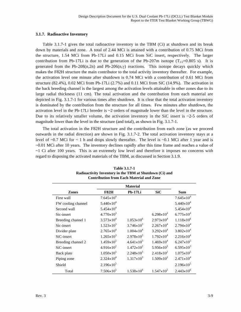
Design Description Document for the U.S. Dual Coolant Pb-17Li (DCLL) Test Blanket ModuleReport to the ITER Test Blanket Working Group (TBWG)
Rev. 3 3-9
3.1.7. Radioactive Inventory
Table 3.1.7-1 gives the total radioactive inventory in the TBM (Ci) at shutdown and its break
down by materials and zone. A total of 2.44 MCi is attained with a contribution of 0.75 MCi from
the structure, 1.54 MCi from Pb-17Li and 0.15 MCi from SiC insert, respectively. The larger
contribution from Pb-17Li is due to the generation of the Pb-207m isotope (T1/2=0.805 s). It is
generated from the Pb-208(n,2n) and Pb-206(n, ) reactions. This isotope decays quickly which
makes the F82H structure the main contributor to the total activity inventory thereafter. For example,
the activation level one minute after shutdown is 0.74 MCi with a contribution of 0.61 MCi from
structure (82.4%), 0.02 MCi from Pb-17Li (2.7%) and 0.11 MCi from SiC (14.9%). The activation in
the back breeding channel is the largest among the activation levels attainable in other zones due to its
large radial thickness (11 cm). The total activation and the contribution from each material are
depicted in Fig. 3.1.7-1 for various times after shutdown. It is clear that the total activation inventory
is dominated by the contribution from the structure for all times. Few minutes after shutdown, the
activation level in the Pb-17Li breeder is ~2 orders of magnitude lower than the level in the structure.
Due to its relatively smaller volume, the activation inventory in the SiC insert is ~2-5 orders of
magnitude lower than the level in the structure (and total), as shown in Fig. 3.1.7-1.
The total activation in the F82H structure and the contribution from each zone (as we proceed
outwards in the radial direction) are shown in Fig. 3.1.7-2. The total activation inventory stays at a
level of ~0.7 MCi for ~ 1 h and drops slowly thereafter. The level is ~0.1 MCi after 1 year and is
~0.01 MCi after 10 years. The inventory declines rapidly after this time frame and reaches a value of
~1 Ci after 100 years. This is an extremely low level and therefore it imposes no concerns with
regard to disposing the activated materials of the TBM, as discussed in Section 3.1.9.
Table 3.1.7-1
Radioactivity Inventory in the TBM at Shutdown (Ci) and
Contribution from Each Material and Zone
Material
Zones F82H Pb-17Li SiC Sum
First wall 7.645 104 7.645 10
4
FW cooling channel 5.440 104 5.440 10
4
Second wall 5.454 104 5.454 10
4
Sic-insert 4.770 103 6.298 10
4 6.775 104
Breeding channel 1 3.573 104 1.053 10
6 2.973 104 1.118 10
6
Sic-insert 1.523 103 3.746 10
3 2.267 104 2.794 10
4
Divider plate 2.765 104 1.004 10
4 3.292 104 3.802 10
4
SiC-insert 1.265 103 2.978 10
3 1.792 104 2.216 10
4
Breeding channel 2 1.459 105 4.641 10
5 1.469 104 6.247 10
5
SiC-insert 4.916 102 1.472 10
2 5.956 103 6.595 10
3
Back plate 1.050 105 2.248 10
3 2.418 102 1.075 10
5
Piping zone 2.324 104 1.317 10
3 1.509 102 2.471 10
4
Shield 2.196 105 2.196 10
5
Total 7.506 105 1.538 10
6 1.547 105 2.443 10
6

Design Description Document for the U.S. Dual Coolant Pb-17Li (DCLL) Test Blanket ModuleReport to the ITER Test Blanket Working Group (TBWG)
3-10 Rev. 3
10–5
10–4
10–3
10–2
10–1
10 0
10 1
10 2
10 3
10 4
10 5
10 6
10 7
10
Tota
l Act
ivity
(Ci)
–1 100 101 102 103 104 105 106 107 108 109 1010 1011
F82HLiPbSiCTotal
Time after Shutdown (s)
1 s 1 m 1 h 1 d 1 mo 1 y 10 y 100 y 1000 y
TBM dimension64.5 cm toroidal194 cm poloidal200.2 cm radial (including 128 cm shield)
Fig. 3.1.7-1. Total activity generated in the test blanket module and contribution from each material.
10–5
10–4
10–3
10–2
10–1
100
101
102
103
104
105
106
10–1 100 101 102 103 104 105 106 107 108 109 1010 1011
FWFW cooling chnlSecond wallSiC insertBreeding chnl1SiC insertDivider plateSiC insertBreeder chnl2SiC insertBack platePiping zoneShieldTotal
Time after Shutdown (s)
Tota
l Act
ivity
(Ci)
1 s 1 m 1 h 1 d 1 mo 1 y 10 y 100 y 1000 y
TBM dimension64.5 cm toroidal194 cm poloidal200.2 cm radial (including 128 cm shield)
Fig. 3.1.7-2. Total activity in the F82H structure and contribution from each zone.
With regard to the breakdown of the total inventory, it is shown in Fig. 3.1.7-2 that the
contribution from the structure in the shield is dominant up to ~ 1 day after shutdown when the
contribution from the structure in the back breeder channel starts to be the largest. The activation in
the back plate is also large. To be noted that the activation inventories in the first and second wall (0.4
cm-thick) are comparable but they are less than those attainable in the shield, the back breeder
channel, and the back plate. This illustrates the importance of accounting for the activation in zones
other that the FW when assessing the total radioactive inventory in the TBM and blanket in general.
The total radioactive inventory in the Pb-17Li breeder and the contribution from each zone are
shown in Fig. 3.1.7-3. It drops rapidly from ~1.5 MCi at shutdown to ~0.01 MCi in one minute due
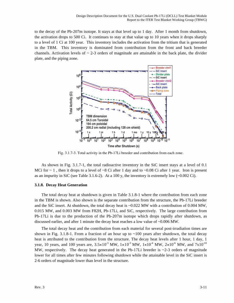
Design Description Document for the U.S. Dual Coolant Pb-17Li (DCLL) Test Blanket ModuleReport to the ITER Test Blanket Working Group (TBWG)
Rev. 3 3-11
to the decay of the Pb-207m isotope. It stays at that level up to 1 day. After 1 month from shutdown,
the activation drops to 500 Ci. It continues to stay at that value up to 10 years when it drops sharply
to a level of 1 Ci at 100 year. This inventory includes the activation from the tritium that is generated
in the TBM. This inventory is dominated from contribution from the front and back breeder
channels. Activation levels of ~ 2-3 orders of magnitude are attainable in the back plate, the divider
plate, and the piping zone.
10–4
10–2
100
102
104
106To
tal A
ctiv
ity (C
i)
10–1 100 101 102 103 104 105 106 107 108 109 1010 1011
Breeder chnl1SiC insertDivider plateSiC insertBreeder chnl2SiC insertBack platePiping zoneTotal
Time after Shutdown (s)
1 s 1 m 1 h 1 d 1 mo 1 y 10 y 100 y 1000 y
TBM dimension64.5 cm Toroidal194 cm poloidal200.2 cm radial (including 128 cm shield)
Fig. 3.1.7-3. Total activity in the Pb-17Li breeder and contribution from each zone.
As shown in Fig. 3.1.7-1, the total radioactive inventory in the SiC insert stays at a level of 0.1
MCi for ~ 1 , then it drops to a level of ~8 Ci after 1 day and to ~0.08 Ci after 1 year. Iron is present
as an impurity in SiC (see Table 3.1.6-2). At a 100 y, the inventory is extremely low (~0.002 Ci).
3.1.8. Decay Heat Generation
The total decay heat at shutdown is given in Table 3.1.8-1 where the contribution from each zone
in the TBM is shown. Also shown is the separate contribution from the structure, the Pb-17Li breeder
and the SiC insert. At shutdown, the total decay heat is ~0.022 MW with a contribution of 0.004 MW,
0.015 MW, and 0.003 MW from F82H, Pb-17Li, and SiC, respectively. The large contribution from
Pb-17Li is due to the production of the Pb-207m isotope which drops rapidly after shutdown, as
discussed earlier, and after 1 minute the decay heat reaches a low value of ~0.006 MW.
The total decay heat and the contribution from each material for several post-irradiation times are
shown in Fig. 3.1.8-1. From a fraction of an hour up to ~100 years after shutdown, the total decay
heat is attributed to the contribution from the structure. The decay heat levels after 1 hour, 1 day, 1
year, 10 years, and 100 years are, 3.5 10-3 MW, 1 10-3 MW, 1 10-4 MW, 2 10-6 MW, and 7x10⁻¹⁰
MW, respectively. The decay heat generated in the Pb-17Li breeder is ~2-3 orders of magnitude
lower for all times after few minutes following shutdown while the attainable level in the SiC insert is
2-6 orders of magnitude lower than level in the structure.
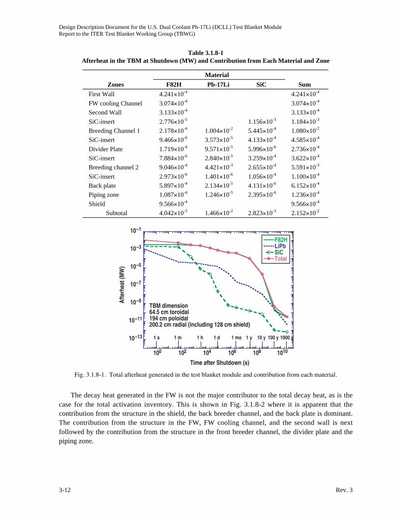
Design Description Document for the U.S. Dual Coolant Pb-17Li (DCLL) Test Blanket ModuleReport to the ITER Test Blanket Working Group (TBWG)
3-12 Rev. 3
Table 3.1.8-1
Afterheat in the TBM at Shutdown (MW) and Contribution from Each Material and Zone
Material
Zones F82H Pb-17Li SiC Sum
First Wall 4.241 10-4 4.241 10-4
FW cooling Channel 3.074 10-4 3.074 10-4
Second Wall 3.133 10-4 3.133 10-4
SiC-insert 2.776 10-5 1.156 10-3 1.184 10-3
Breeding Channel 1 2.178 10-4 1.004 10-2 5.445 10-4 1.080 10-2
SiC-insert 9.466 10-6 3.573 10-5 4.133 10-4 4.585 10-4
Divider Plate 1.719 10-4 9.571 10-5 5.996 10-6 2.736 10-4
SiC-insert 7.884 10-6 2.840 10-5 3.259 10-4 3.622 10-4
Breeding channel 2 9.046 10-4 4.421 10-3 2.655 10-4 5.591 10-3
SiC-insert 2.973 10-6 1.401 10-6 1.056 10-4 1.100 10-4
Back plate 5.897 10-4 2.134 10-5 4.131 10-6 6.152 10-4
Piping zone 1.087 10-4 1.246 10-5 2.395 10-6 1.236 10-4
Shield 9.566 10-4 9.566 10-4
Subtotal 4.042 10-3 1.466 10-2 2.823 10-3 2.152 10-2
10–13
10–11
10–9
10–7
10–5
10–3
10–1
100 102 104 106 108 1010
F82HLiPbSiCTotal
Time after Shutdown (s)
1 s 1 m 1 h 1 d 1 mo 1 y 10 y 100 y 1000 y
TBM dimension
Afte
rhea
t (M
W)
64.5 cm toroidal194 cm poloidal200.2 cm radial (including 128 cm shield)
Fig. 3.1.8-1. Total afterheat generated in the test blanket module and contribution from each material.
The decay heat generated in the FW is not the major contributor to the total decay heat, as is the
case for the total activation inventory. This is shown in Fig. 3.1.8-2 where it is apparent that the
contribution from the structure in the shield, the back breeder channel, and the back plate is dominant.
The contribution from the structure in the FW, FW cooling channel, and the second wall is next
followed by the contribution from the structure in the front breeder channel, the divider plate and the
piping zone.

Design Description Document for the U.S. Dual Coolant Pb-17Li (DCLL) Test Blanket ModuleReport to the ITER Test Blanket Working Group (TBWG)
Rev. 3 3-13
10
Afte
rhea
t (M
W)
-12
10-11
10-10
10-9
10-8
10-7
10-6
10-5
10-4
10-3
10-2
10-1 100 101 102 103 104 105 106 107 108 109 1010 1011
FWFW cooling chnlSecond wall SiC insertBreeding chnl1SiC insertDivider plateSiC insertBreeder chnl2SiC insertBack platePiping zoneShieldTotal
Time after Shutdown (s)
1 s 1 m 1 h 1 d 1 mo 1 y 10 y 100 y 1000 y
TBM dimension64.5 cm toroidal194 cm poloidal200.2 cm radial (including 128 cm shield)
Fig. 3.1.8-2. Total afterheat in the F82H structure and contribution from each zone.
The total decay heat generated in the Pb-17Li breeder and the contribution from each zone is
depicted in Fig. 3.1.8-3. The decay heat after 1hour, 1 day, 1 year, 10 years and 100 years after
shutdown are ~3 10-5 MW, ~1 10-5 MW, ~9 10-8 MW, 1 10-9 MW, and 3 10-10 MW, respectively.
The decay heat generated in the front and back breeder channels are the largest among the other
zones. The decay heat generated in the divider plate zone is about two orders of magnitude lower
than the values in these channels.
10–12
10–11
10–10
10–9
10–8
10–7
10–6
10–5
10–4
10–3
10–2
10–1
10 –1 10 0 101 102 103 104 105 106 107 108 109 10 10 10 11
Breeder chnl1SiC insertDivider plateSiC insertBreeder chnl2SiC insertBack platePiping zoneTotal
Time after Shutdown (s)
1 s 1 m 1 h 1 d 1 mo 1 y 10 y 100 y 1000 y
TBM dimension64.5 cm toroidal194 cm poloidal200.2 cm radial (including 128 cm shield)
Afte
rhea
t (M
W)
Fig. 3.1.8-3. Total afterheat in the Pb-17Li breeder and contribution from each zone.
The total decay heat generated in the SiC inserts is larger than the decay heat generated in the Pb-
17Li breeder for few minutes after shutdown, as shown in Fig. 3.1.8-1. It drops sharply thereafter and
reaches very low values. After 1 hour, 1 day, 1 year, 10 years, and 100 years following shutdown,

Design Description Document for the U.S. Dual Coolant Pb-17Li (DCLL) Test Blanket ModuleReport to the ITER Test Blanket Working Group (TBWG)
3-14 Rev. 3
these values are 1 10-5 MW, 2 10-8 MW, 1 10-10 MW, 8 10-11 MW, and 1 10-12 MW, respectively.
These values are insignificant and impose no safety concerns.
3.1.9. Radwaste Assessment
The waste disposal rating (WDR) depends on the level of the long-term activation. For the F82H
structure, Nb-94 (T1/2 = 2.03 104 y), Mn-53 (T1/2 = 3.7 106 y) Ni-59 (T1/2 =7.5 104 y), and Nb-91
(T1/2 = 6.8 1 02 y) are the main contributors. In Pb-17Li, the main contributor to the long-term
activation is the Pb-205 isotope (T1/2 = 1.52 107 y) while the C-14 isotope (T1/2 = 5730 y) and the Be-
10 isotope (T1/2 = 1.51 106 y) are the main contributors in the SiC insert. The radwaste classification
of these materials was evaluated according to the Nuclear Regulatory Commission [3.1.9-1] (NRC)
10FR61 and Fetter [3.1.9-2] waste disposal concentration limits. The limits given are based on the
assumption that all solid components are crushed before being disposed (no voids). Components
having WDR >1, according to Class C limits, do not qualify for shallow land burial.
The WDR values for F82H structure, the Pb-17Li breeder, and the SiC insert are 6.9 10-3,
2.9 10-9, and 7.3 10-14, respectively, based on the NRC limits. The corresponding WDRs based on
Fetter limits are 1.3 10-2, 8.7 10-3, and 2.1 1 0-4, respectively. Although the Fetter limits are
generally more conservative, still the values are much lower than unity and therefore these materials
are qualified for shallow land burial according to the Class C limits.
References for Section 3.1.9
[3.1.9-1] Nuclear Regulatory Commission, 10CFR part 61, "Licensing Requirements for Land
Disposal of Radioactive Waste," Federal Register, FR 47, 57446 (1982).
[3.1.9-2] S. Fetter, E. Cheng, F. Mann, "Long Term Radioactive Waste from Fusion Reactors,"
Fusion Engin. and Design 13 (1990) 239.
3.1.10. Summary
Neutronics calculations were performed to determine the relevant nuclear performance
parameters for the DCLL TBM. These include tritium breeding, nuclear heating, radiation damage,
and shielding requirements. The neutron wall loading at the TBM is 0.78 MW/m2. The front surface
area of the module is 1.25 m2. A 2 mm thick beryllium layer is utilized as a plasma facing material
on the ferritic steel FW. The lithium in the lead lithium (Pb-17Li) eutectic is enriched to 90% Li-6.
The ferritic steel alloy F82H is used for structural material. The total radial depth of the TBM is 41.3
cm followed by a 30 cm thick inlet/outlet piping zone. A separate 316SS/H2O shield plug is used
behind the TBM.
The calculated local tritium breeding ratio (TBR) in the DCLL TBM is only 0.741 because of the
relatively small thickness used. During a D-T pulse with 500 MW fusion power, tritium is produced
in the TBM at the rate of 3.2 1017 atoms/s (1.59 10-6 g/s). For the planned 3000 pulses per year the
annual tritium production in the TBM is 2.4 g/year. Nuclear heating profiles in the different blanket
constituent materials were determined for use in the thermal hydraulics analysis. The total nuclear
heating in the TBM is 0.982 MW. Adding the surface heating, the total thermal power to be removed
from the TBM is 1.357 MW. The He coolant carries about 54% of that power. For the ITER fluence
goal of 0.3 MWa/m2, the peak cumulative dpa and He production in the FW are 5.7 dpa and 64 appm,
respectively. The cumulative end-of-life He production in the inlet/outlet pipes is 0.34 appm allowing

Design Description Document for the U.S. Dual Coolant Pb-17Li (DCLL) Test Blanket ModuleReport to the ITER Test Blanket Working Group (TBWG)
Rev. 3 3-15
for rewelding. We estimated that ~1 m thick shield plug is required behind the DCLL TBM to allow
personnel access for maintenance.
The radioactivity inventory and afterheat in the TBM were assessed at shutdown and at several
post-irradiation times. Also assessed is the waste disposal rating (WDR) of various components of the
TBM. The pulsed operation mode in ITER were accounted for and thus allowing for the decay of the
accumulated radionuclides between pulses. The TBM is assumed to be placed in the test port when
the 14.1 MeV neutrons are generated (fifth year) and stays in the port until an accumulated fluence of
0.3 MWa/m2 is reached. (tenth year). Although 3-4 types of TBM may be utilized for testing during
that period, the results reported here give upper conservative estimates for the activation and afterheat
levels under the assumption of no replacement for the TBR.
The total radioactive inventory in the TBM (Ci) at shutdown is relatively small (2.44 MCi ) and
drops rapidly within a minute to reach a level of ~0.7 MCi due to the decay of the Pb-207m isotope. It
stays at that level for ~ 1 h and drops slowly thereafter. The level is ~0.1 MCi after 1 year and is
~0.01 MCi after 10 years. The inventory declines rapidly after this time frame and reaches a value of
~1 Ci after 100 years. This inventory is almost entirely due to the activation of the F82H structure in
the TBM, and in particular, to the structure in the back breeder channel, the back plate, and the shield.
The activation inventories in the first and second wall (0.4 cm-thick) are comparable but they are less
than the level attainable in these large zones. Few minutes after shutdown, the activation level in the
Pb-17Li breeder is ~2 orders of magnitude lower than the level in the structure, even with the
inclusion of the activation of the tritium bred. Due to its relatively smaller volume, the activation
inventory in the SiC insert is ~2-5 orders of magnitude lower than the level in the structure (and
total).
At shutdown, the total decay heat is as low as ~0.022 MW. After the decay of the Pb-207m
isotope, the total decay heat is attributed mainly to the structure. The total decay heat after 1 hour, 1
day, 1 year, 10 years, and 100 years are, 3.5 10-3 MW, 1 10-3 MW, 1 10-4 MW, 2 10-6, and 7 10-10
MW, respectively. These are extremely low values and impose no safety concerns. As is the case for
the radioactive inventory, the decay heat generated in the FW is not the major contributor to the total
decay heat. The contribution from the structure in the shield, the back breeder channel, and the back
plate is dominant. The decay heat generated in the Pb-17Li breeder is ~2-3 orders of magnitude
lower for all times after few minutes following shutdown while the attainable level in the SiC insert is
2-6 orders of magnitude lower than level in the structure.
The waste disposal rating (WDR) depends on the level of the long-term activation. For the F82H
structure, Nb-94 (T1/2=2.03 104 y), Mn-53 (T1/2=3.7 106 y) Ni-59 (T1/2=7.5 104 y), and Nb-91
(T1/2=6.8 102 y) are the main contributors. In Pb-17Li, the main contributor is the Pb-205 isotope
(T1/2=1.52 107 y) while the C-14 isotope (T1/2=5730 y) and the Be-10 isotope (T1/2=1.51 106 y) are
the main contributors in the SiC insert. The WDR values for F82H structure, the Pb-17Li breeder,
and the SiC insert are 6.9 10-3, 2.9 10-9, and 7.3 10-14, respectively, based on the NRC limits. The
corresponding WDRs based on Fetter limits are 1.3 10-2, 8.7 10-3, and 2.1 10-4, respectively. It was
assumed that all solid components are crushed before being disposed (no voids). Although the Fetter
limits are generally more conservative, still the values are much lower than unity and therefore these
materials are qualified for shallow land burial according to the Class C limits.

Design Description Document for the U.S. Dual Coolant Pb-17Li (DCLL) Test Blanket ModuleReport to the ITER Test Blanket Working Group (TBWG)
3-16 Rev. 3
3.2. THERMO-HYDRAULIC ANALYSIS
3.2.1. MHD Analysis
3.2.1.1. Flow in the Poloidal Ducts with FCI. Flow Channel Insert (FCI) made of silicon carbide
composite (SiCf/SiC) is the central element of the DCLL concept. To address the MHD pressure drop,
insulating properties of the FCI, and the velocity in the poloidal channels of the module, numerical
computations were performed. The liquid moves slowly (about 10 cm/s) upward through the front
channels, and then downward through the return (back) channels. The cross-sectional dimensions of
the front and back channels are slightly different (see Section 2.2.1). The mathematical model used,
assumes fully developed, laminar flow [3.2.1-1]. The flows in the channels are considered separately,
without taking into account possible electromagnetic coupling between them. However, the effect of
electromagnetic coupling between the bulk flow and the flow in the thin gap of the same channel is
considered. The computer code [3.2.1-2] solves the governing equations in the domain that includes
the bulk flow region, FCI, gap flow region, and the ferritic wall. The electrical conductivity of the SiC
composite can vary in a wide range (1-500 S/m), depending on the fabrication technique, neutron
irradiation and many other factors. In the present MHD calculations, the electrical conductivity is 20
S/m, and the FCI thickness is 5 mm. The magnetic field (toroidal) is 4 T. As shown in Ref. 3.2.1-1,
such FCI reduces the MHD pressure drop by about 100 times as compared to the same flow without
insulation.
Figure 3.2.1-1 shows the computational mesh, induced magnetic field distribution and velocity
profile. The flow demonstrates two velocity jets near the side walls (the walls parallel to the magnetic
field) indicating that the FCI is not a perfect insulator. One should distinguish two sections of the gap:
parallel (side gap) and perpendicular (Hartmann gap) to the magnetic field. In the two Hartmann gaps,
the flow is almost stagnant, while in the two side gaps it can be as high as that in the jet flow in the
bulk region. The terminology “side” and “Hartmann” is used here in analogy with standard MHD
flows in rectangular channels. As shown in Ref. 3.2.1-1, such a velocity distribution has a significant
effect on heat transfer. However, heat transfer conditions in Ref. 3.2.1-1 (reference DCLL blanket)
are different from those for the ITER TBM. Therefore, basic conclusions on heat transfer deduced in
Ref. 3.2.1-1 are not directly applicable to the present concept. Specific heat transfer analysis is thus
required for the ITER TBM.
3.2.1.2. MHD Pressure Drop in the Module. Liquid metal enters the module at its bottom from the
outer annulus of the concentric pipe. From the inlet poloidal manifold it is distributed into the three
front poloidal rectangular channels, where it flows upwards. At the top of the module, the liquid metal
makes a 180° turn and then flows downwards through the three return (back) channels. At the bottom
of the module, the liquid metal is collected and leaves the TBM from the outlet manifold through the
internal tube of the concentric pipe. Electrical insulation of the flows is provided via SiCf/SiC FCIs.
For the flow details and sketches see Section 2.2.1. The goal of the present analysis is to estimate the
MHD pressure drop over the whole Pb-17Li flow path when the TBM works in a high performance
regime. The parameters of the high performance regime are the following: Pb-17Li TBM inlet
temperature is 400°C; Pb-17Li TBM outlet temperature is 650°C; Pb-17Li mass flow rate is 13 kg/s.
The flow can be subdivided into the following components:
1. Counter-current flow in the concentric pipe within a near-uniform magnetic field.
2. Flow in the concentric pipe in a fringing magnetic field.

Design Description Document for the U.S. Dual Coolant Pb-17Li (DCLL) Test Blanket ModuleReport to the ITER Test Blanket Working Group (TBWG)
Rev. 3 3-17
Fig. 3.2.1-1. MHD flow in the front poloidal channel with FCI: computational mesh (a); induced magnetic fieldlines (b); velocity profile (c). Velocity is scaled with the mean velocity; z and y are scaled with b (half of thechannel width).
3. Flow in the inlet poloidal manifold.
4. Flow in the front channels including radial flows at the module bottom and top.
5. Flow in the return channels.
6. Flow in the outlet manifold.
The external Pb-17Li flow circuit and the bypass system are located outside the strong magnetic
field region and therefore not included in the MHD analysis. Almost all flows are electrically
connected since SiCf/SiC is not a perfect insulator. Vertical flows in the poloidal channels will also be
affected by natural convection. Appearance of two-dimensional turbulence is quite possible. These
effects are of primary importance when considering heat and mass (tritium transport) transfer and will
be taken into consideration in the future. At present, their influence on MHD pressure drop is not
taken into account.
Poloidal Front Channels with Radial Sections. The front channel has the following
dimensions: 0.18 m (toroidal); 0.08 m (radial); 1.9 m (poloidal). The channels extend to short radial

Design Description Document for the U.S. Dual Coolant Pb-17Li (DCLL) Test Blanket ModuleReport to the ITER Test Blanket Working Group (TBWG)
3-18 Rev. 3
sections at the module bottom and top. Changes in the flow direction from radial to poloidal at the
bottom, and from poloidal to radial and then to poloidal at the top occur in the plane perpendicular to
the magnetic field. Therefore, the MHD pressure drop associated with the induced axial electric
currents is smaller than that caused by the cross-sectional currents. The latter was calculated
numerically assuming fully developed flow conditions for a 5 mm thick FCI with electrical
conductivity of SiCf/SiC 20 S/m and in a 4 T magnetic field. The flow velocity is 0.0975 m/s. In the
calculations, the total flow length was extended to 2.1 m by taking into account radial flow sections.
The pressure gradient is
d P/d x = 1882 U .
Poloidal Return (back) Channels. The analysis for the back channel is similar to that for the
front channels. The dimensions are slightly different: 0.18 m (toroidal); 0.12 m (radial); 1.9 m
(poloidal). The velocity is 0.065 m/s. The pressure gradient is
d P/d x = 3947 U .
Flow in the Concentric Pipe within a Near-Uniform Magnetic Field. The internal concentric
pipe is insulated inside. Providing that electrical resistance of the FCI is high enough, the MHD
pressure drop in the flow through the internal pipe can be estimated assuming perfect insulation
conditions. Perfect insulation also suggests that the internal flow and the annulus flow are decoupled.
The flow in the annulus is insulated only from the external side. At the internal side, liquid metal
contacts with the ferritic wall. The MHD pressure drop for a non-conducting pipe is calculated with
the following formula [3.2.1-3]:
d P
d x
=U
R2
3
8
Ha . (3.2.1-1)
Here, the Hartmann number is built through the internal pipe radius R = 0.017 m. The MHD pressure
drop in the annulus flow is calculated via numerical computations for the magnetic field at 3.7 T. The
pressure gradient in the annulus is
d P/d x = 9370 U . The computations also showed that the
velocity in the annulus has a maximum at the top and bottom and is fully stagnant at two point
locations at the left and right sides. This velocity distribution was approximated with the following
formula:
U = 0.5U0 sin . (3.2.1-2)
Here, U0 is the mean velocity in the annulus, = 3.141, and is the azimuthal angle. Equation
(3.2.1-2) is used in Section 3.2.1.3 in the heat transfer calculations
Flow in the Concentric Pipe in a Fringing Magnetic Field. Reliable techniques for calculating
MHD pressure drop for flows in a fringing magnetic field are not available. This part of MHD
pressure losses is associated with the axial currents and cannot be eliminated by insulation. The
following formula is recommended in Ref. 3.2.1-4:
= P/ U2
/ 2
= k Ha
2/ Re . (3.2.1-3)
For an abruptly changing magnetic field, the coefficient k in the pipe flow is about 0.5. In the
absence of correlations for the annulus flows, the same pressure is assumed in the annulus.
Flow in the Inlet Poloidal Manifold. The same empirical correlation, Eq. (3.2.1-3), is applied.
For different geometries reported in special literature [3.2.1-5], recommended values for k range
from 0.25 to 2. Based on this information and taking into account the complex fluid redistribution in
the manifold, we use here k = 1 2.

Design Description Document for the U.S. Dual Coolant Pb-17Li (DCLL) Test Blanket ModuleReport to the ITER Test Blanket Working Group (TBWG)
Rev. 3 3-19
Flow in the Outlet Manifold. The pressure drop is calculated using the same procedure as
explained for the inlet manifold.
All MHD pressure drop calculated above are summarized in Table 3.2.1-1. The table also shows
the pressure drop for each component as a fraction of the total MHD pressure drop. One can see that
the MHD pressure losses in the poloidal channels are much smaller than the 3-D MHD pressure drops
associated with the manifolds and a fringing magnetic field.
Table 3.2.1-1
MHD Pressure Drops in the TBM
Flow
Pi(MPa)
Pi / P(%)
Front channels 0.384 10-3 0.13
Return channels 0.485 10-3 0.16
Concentric pipe (internal, uniform B-field) 15.4 10-3 5.1
Concentric pipe (annulus, uniform B-field) 0.0286 9.5
Concentric pipe (internal, fringing B-field) 0.0585 19.3
Concentric pipe (annulus, fringing B-field) 0.0585 19.3
Inlet manifold 0.070-0.140 23.2
Outlet manifold 0.070-0.140 23.3
Total 0.302-0.442 100
3.2.1.3. Heat Transfer in the Concentric Pipe. The goal of this analysis is to assure that the
maximum temperature of the internal ferritic wall is below the allowable temperature limit. Heating
of the ferritic wall occurs due to radial heat leakage from the internal pipe with the “hot” Pb-17Li
inside. Thermal calculations were performed using commercial CFD software FLUENT. The cross-
sectional area of the concentric pipe is shown in Fig. 3.2.1-2. The radial velocity profile obtained in
the MHD analysis (as described in the previous sections) was used to define the flow in the thermal
calculations. Uniform velocity distribution was assumed for the internal pipe. Equation (3.2.1-2)
gives the velocity profile in the annulus. No flow in the thin gap between the FCI and the internal
ferritic wall was assumed first. The other variant suggested uniform flow in the gap with the same
velocity as in the internal pipe. Typical temperature distribution over the cross-sectional area is shown
in Fig. 3.2.1-3. Maximum temperatures occur at the points of minimum velocity. The maximum
temperature of the ferritic wall in the calculations is slightly higher for the case with no flow in the
gap, but does not exceed the compatibility limit of 475°C.
FCI5 mm Thick
1 mm Pb-17Li Gap
3 mm FeInner Wall
Cold Pb-17Li
Hot Pb-17Li
MagneticField
Fig. 3.2.1-2. Cross-section of the concentric pipe.

Design Description Document for the U.S. Dual Coolant Pb-17Li (DCLL) Test Blanket ModuleReport to the ITER Test Blanket Working Group (TBWG)
3-20 Rev. 3
Fig. 3.2.1-3. Cross-sectional temperature distribution (°C) in the concentric pipe.
3.2.1.4. Heat Transfer in the Poloidal Channels. Velocity profiles in the poloidal channels
calculated in Section 3.2.1.1 are used as input data in heat transfer calculations. The 3-D energy
equation that describes the temperature field in the module and the computer code that solves this
equation are presented in Ref. 3.2.1-1. The analysis was performed for the reference TBM design (Pb-
17Li inlet/outlet temperature is 360/470°C). In this regime, the temperature losses into the He are
driven by relatively small temperature gradients; there are no special requirements imposed on the
thermal conductivity of the insert. Therefore, all calculations were performed at kSiC=15 W/m-K. The
heat transfer coefficient in the He flows was estimated as 4000 W/m2-K. The calculations are
performed in two steps: for the front channel first, and then for the back (return) channel. When doing
so, the temperature at the exit of the front channel is used as an inlet temperature in the calculations of
the back channel. The bulk temperature distribution in the breeder along the Pb-17Li flow path is
shown in Fig. 3.2.1-4.
Fig. 3.2.1-4. Bulk temperature in the poloidal channels.

Design Description Document for the U.S. Dual Coolant Pb-17Li (DCLL) Test Blanket ModuleReport to the ITER Test Blanket Working Group (TBWG)
Rev. 3 3-21
Most of the temperature increase occurs in the front channel, where the volumetric heating is
sufficiently higher. The shape of the curve over each channel departs slightly from the straight line,
indicating some heat losses. A detailed 2-D temperature distribution at the exit of the front channel is
shown in Fig. 3.2.1-5. The maximum interface temperatures can be seen from the radial temperature
distributions in Fig. 3.2.1-6, which shows the temperatures along the channel axis at the exit of each
channel. The analysis performed has shown that the referenced temperature increase of 110 K can be
achieved, while all the interface temperatures are sufficiently lower than the maximum allowable
temperatures.
Fig. 3.2.1-5. Temperature at the exit of the front channel. The domainincludes: Pb-17Li flows, SiCf/SiC FCI, First Wall, FS grid, He flows.
Fig. 3.2.1-6. Radial temperature distribution in: FS wall (I); gap (II);SiCf/SiC FCI (III); Pb-17Li core flow (IV) at the exit of each channel.

Design Description Document for the U.S. Dual Coolant Pb-17Li (DCLL) Test Blanket ModuleReport to the ITER Test Blanket Working Group (TBWG)
3-22 Rev. 3
Reference for Section 3.2.1
[3.2.1-1] S. Smolentsev, M. Abdou, N.B. Morley, M. Sawan, S. Malang, C. Wong, "Numerical
analysis of MHD flow, heat transfer and tritium transport in a poloidal channel of the DCLL
blanket with a SiCf/SiC flow channel insert," ISFNT-7, Japan, 2005.
[3.2.1-2] S. Smolentsev, N.B. Morley, M. Abdou, "Code development for analysis of MHD pressure
drop reduction in a liquid metal blanket using insulation technique based on a fully
developed flow model," Fusion Engin. Design 73 (2005) 83.
[3.2.1-3] J.A. Shercliff, "Magnetohydrodynamic pipe flow," Part 2. High Hartmann number, JFM 13
(1962) 513-518.
[3.2.1-4] V.A. Glukhih, A.V. Tananaev, I.R. Kirillov, "Magnetohydrodynamics in Fusion," (in
Russian), Moscow, Energoatomizdat, 1987.
[3.2.1-5] I.R. Kirillov, C.B. Reed, L. Barleon, K. Miyazaki, "Present understanding of MHD and heat
transfer phenomena for liquid metal blankets," Fusion Engin. Design 27 (1995) 553.
3.2.2. First Wall Helium Flow Distribution
3.2.2.1. First Wall Helium Flow Distribution Procedure. Computational Fluid Dynamic (CFD)
calculations using the commercial software FLUENT [3.2.2-1], were performed to determine the
helium gas flow distribution in the channels of the first wall (FW). Results of the calculations were
used to evaluate and optimize the design of the headers for the FW helium flow circuits. In addition
to determining channel flow distribution, the CFD analysis also calculates pressure losses in the
headers.
Cooling of the FW is achieved with two counter-flowing helium circuits. Each circuit consists of
eight channels making five passes of the FW (see schematic, Fig. 3.2.2-1). Helium transitions from
one pass to the next through headers. The configuration of the headers determines the uniformity of
channel flow distribution from one pass to the next.
The three-dimensional CFD model consists of a single header with eight inlet channels and eight
outlet channels (see Fig. 3.2.2-2). The mass flow rate is defined for each channel inlet and the
resulting steady-state outlet rates are calculated. Flow distribution through subsequent down-stream
headers is then determined by defining the inlet mass flow rates using the outlet channel results of the
up-stream header calculation. In this way it is possible to evaluate the flow distribution through an
entire first wall helium circuit.
Turbulence is accounted for by utilizing the k-epsilon turbulence model. Helium density is
defined as 5.7 kg/m3 and Helium viscosity, as 3.5x10⁻⁵ kg/m-s.
3.2.2.2. First Wall Helium Flow Distribution Results. Uniform flow distribution to the channels
can be achieved, either with a constant header cross section area that is equal to or greater than three
times the sum of the cross section areas of the down stream channels, or by varying the header cross
section to maintain a constant flow velocity along the header [3.2.2-2]. Space restrictions along with
ease of fabrication requirements preclude either of these configurations from being applied for TBM.

Design Description Document for the U.S. Dual Coolant Pb-17Li (DCLL) Test Blanket ModuleReport to the ITER Test Blanket Working Group (TBWG)
Rev. 3 3-23
Fig. 3.2.2-1. Schematic layout of one (of two) first wall He flow circuit.
Fig. 3.2.2-2. CFD header model.
Considering the TBM design constraints, five different header configurations, incorporating both
fixed and variable cross-sections, were evaluated. Of the five header configurations, analysis results
indicate that a 65mm x 85mm fixed-area header configuration (see Fig. 3.2.2-2) achieves the most
uniform flow distribution, with outlet channel flows varying by as much as 12%. Therefore, in order
to meet a minimum channel flow velocity of 42.6 m/s, some channels experience velocities as high as
49.3 m/s. Figure 3.2.2-3 summarizes the flow distribution by plotting the outlet velocity results for a
single circuit. The average pressure loss for the headers is 0.0148 MPa.

Design Description Document for the U.S. Dual Coolant Pb-17Li (DCLL) Test Blanket ModuleReport to the ITER Test Blanket Working Group (TBWG)
3-24 Rev. 3
40
42
44
46
48
50
1 2 3 4 5 6 7 8Outlet Channels
Velo
city
(m/s
)
Header Pass 1 to Pass 2Header Pass 2 to Pass 3Header Pass 3 to Pass 4
Header Pass 4 to Pass 5
Fig. 3.2.2-3. Header outlet channel flow distribution. Minimum target velocity 42.6 m/s.
References for 3.2.2
[3.2.2-1] FLUENT, Release: 6.1.22
[3.2.2-2] I.E. Idelchik Handbook of Hydraulic Resistance, Second Edition (Hemisphere Publishing
Corporation, Washington, 1986).
3.2.3. Helium Circuit Pressure Drop Analysis
The DCLL TBM uses a pressurized helium circuit to cool the module in addition to the heat
leaking through the FCI from the lithium lead flow. Most of the heat is from the surface heat flux
generated by the plasma and the volumetric power deposition from the neutrons to the TBM structure.
The required helium mass flow can be calculated with an overall energy balance once the inlet
and outlet temperature of the helium are fixed. The inlet temperature is selected at 360ºC, while the
outlet temperature is at 420ºC in normal operative condition. These values have been optimized to
allow adequate cooling of the first wall.
The average heat flux over the 1.25 m2 plasma facing surface of the module is given as 0.3
MW/m2, thus the total power from surface heat flux is 0.4 MW. The total nuclear heating in the TBM
is 0.982 MW. Of this, 0.623 MW are generated in the lithium lead and extracted by the flowing metal
itself. No leakage from the lithium lead channels is assumed through the thermally insulating SiC
composite FCI. The total power that the helium flow needs to handle is thus 0.734 MW. The
necessary total mass flow is 2.353 kg/s.
To estimate the pressure losses the helium circuit is divided in three main parts, also described in
Fig. 3.2.3-1:
• The TBM, which is formed by 4 parallel circuits in the first wall and the back plate and
internal structure (Fig. 3.2.3-1, refer to Section 2.2.1 for details)
• The flow distribution pipes behind the TBM (refer to Section 2.2.1 for details)
• The connecting pipes from the TBM to the heat exchanger (refer to Section 2.2.1 for details)

Design Description Document for the U.S. Dual Coolant Pb-17Li (DCLL) Test Blanket ModuleReport to the ITER Test Blanket Working Group (TBWG)
Rev. 3 3-25
Inlet / Outlet Pipes
Flow Distribution
TBM
Inlet360°C
2.2 k g/s
Outlet420°C
1.1 kg/s
0.8 kg/s
0.3 kg/s
0.1 kg/s
5 ConsecutiveVertical Sections
FW1
FW2
BW1
BW2
Fig. 3.2.3-1. TBM He cooling circuits.
The components of the TBM have already been introduced in the neutronics analysis of Section 3.1.
The helium circuit inside the TBM is divided in two main parts: the first wall and the internal
structure. The first part includes the plasma facing and side plates. The latter part includes the top and
bottom plates, the flow channel divider, the radial ribs and the back wall. The first wall is cooled by
two counter flowing circuits, one flowing top to bottom, and one bottom to top. From each of the two
circuits a by-pass is used to cool separate components of the internal structure. The design of the
circuit is symmetrical in order to ensure that the flow resistance in each of the parallel circuits is the
same. The scheme of the helium cooling circuit is summarized in Fig. 3.2.3-1. For details refer to the
TBM design description in Section 2.2.1.
The heat generated in the first wall circuit (FW1 and FW2) is due to the radiative flux
contribution (0.4 MW) and the nuclear heating of the first wall and side wall structure (0.17 MW).
This accounts for 78% of the total heat handled by the helium circuit. The remaining 22% is
generated in the internal and back structure circuits (BW1 and BW2). In this analysis we will assume
that 70% of the flow is used to cool the first wall, and 30% the inner and back structure. This is
ensured by balancing the resistive losses in the back plate circuits with the flow restriction imposed
by the by-pass channel size. The pressure drop can then be evaluated considering any of the four
parallel branches of the helium circuit in the TBM (FW1, FW2, BW1 or BW2).
The helium flow in each of the two counter-flow passes of the first wall is 0.8235 kg/s. Each pass
is divided in 8 channels in the inlet/outlet manifolds. The manifolds are designed to cover the first
wall height with 5 consecutive passes. The flow from the 8 parallel channels is collected by the outlet
manifold and guided into the next consecutive section, following the cooling scheme described in
detail in Section 3.2.4. The mass flow of helium in each channel is on average 0.103 kg/s,
corresponding to an average flow velocity of 46.8 m/s. The channel friction coefficient has been

Design Description Document for the U.S. Dual Coolant Pb-17Li (DCLL) Test Blanket ModuleReport to the ITER Test Blanket Working Group (TBWG)
3-26 Rev. 3
calculated for the configuration in which the heat transfer on the plasma side of the channel is
enhanced using transverse square ribs of 1 mm height and 6.3 mm pitch resulting in 0.249 mm of
equivalent roughness. The proposed correlation estimates the friction coefficient f as 0.1148 [3.2.3.1].
The total length of a single pass channel including the plasma facing wall and the TBM sides is
1.272 m. Accordingly, for two 90 degree smooth bends to transition from the sides to the plasma
facing wall, the total pressure drop between inlet and outlet of an average channel is 55.4 kPa
[3.2.3.2]. The pressure drop in the manifolds that collect the flow from the 8 channels and
redistributes it to the next section (above or below depending on the pass direction) has been
estimated with the numerical calculations described in Section 3.2.2 and amounts to 14.8 kPa. Thus
the total pressure drop in one section is 70.2 kPa, and the total pressure drop across the first wall is
0.351 MPa. This assumes that the losses in the entrance and exit manifold are the same as those in
each transition between consecutive passes.
The other main component of the pressure drop occurs along the 80 m inlet and outlet pipes from
the TBM to the heat exchanger building. The inner diameter of the pipes is 76 mm. The total mass
flow is 2.35 kg/s, corresponding to a 90 m/s flow velocity in the pipes. The friction coefficient is
estimated using Petukhov correlation for smooth walls as f = 0.01138 [3.2.3.1]. The helium inlet and
outlet connection to the TBM maintains the coaxial design of the lithium lead circuit (see Section
2.2.1). The inner pipe of the coaxial configuration is the same as the one running to the heat
exchanger building. The outer pipe inner diameter is 120 mm, and is designed to maintain a similar
velocity than the inner pipe. Since the friction coefficient in the annular pipe is also similar, the 10 m
coaxial length can be added to the 80 m of the inlet and outlet pipes outside the transporter to
calculate pressure losses. Considering that 12 smooth bends are needed to accommodate the pipe
distribution through the building, the total losses amount to 0.624 MPa [3.2.3.3]. In the future design
evolution, part of the coaxial pipe leading to the TCWS vault could be changed to two simple pipes
with corresponding thermal insulation on the outside.
Other pressure losses occur in the flow distribution section behind the TBM. This part of the
circuit includes all the pipes, bends and splits between the inlet and outlet manifolds of the first wall
and back plate circuits and the coaxial pipe. Pressure losses are estimated using standard engineering
correlations for smooth pipes and assuming that adequate care will be taken to minimize losses at
bends and collecting manifolds (round corners, large radius turns, etc) [3.2.3.3]. The losses can be
estimated following any of the four branches of the circuit in Fig. 3.2.3-1. The pressure drop in the
flow distribution circuit is estimated as 0.14 MPa.
Total pressure drop in the helium circuit is then estimated as 1.115 MPa, which accounts to
13.9% of the circuit inlet pressure of 8 MPa (Table 3.2.3-1). This is acceptable for a testing
component and can be much reduced for a power production device like the DEMO.
Table 3.2.3-1
Summary of Pressure Drop in the Helium Circuit
Circuit Part
Pressure Drop
(MPa)
Fraction of Inlet Pressure
(%)
Inlet / outlet pipes 0.624 7.8
Flow distribution 0.14 1.7
First wall 0.351 4.4
Total 1.115 13.9

Design Description Document for the U.S. Dual Coolant Pb-17Li (DCLL) Test Blanket ModuleReport to the ITER Test Blanket Working Group (TBWG)
Rev. 3 3-27
References for Section 3.2.3
[3.2.3-1] A.F. Mills Basic Heat and Mass Transfer, Second edition (Prentice Hall, Upper Saddle
River, New Jersey, 1999).
[3.2.3-2] J.A Roberson, C.T. Crowe Engineering Fluid Mechanics, Third Edition (Houghton Mifflin
Company, Boston, 1985).
[3.2.3-3] I.E. Idelchik, Handbook of Hydraulic Resistance, Second Edition (Hemisphere Publishing
Corporation, Washington, 1986).
3.2.4. First Wall Thermal-Hydraulic Analysis
3.2.4.1. Steady State Analysis Procedure. Computational Fluid Dynamic (CFD) calculations using
the commercial software FLUENT [3.2.4-1], were performed to evaluate the thermal performance of
the first wall (FW), specifically, the maximum first wall temperature, helium outlet temperature and
the heat transfer coefficients in the channels.
The FW is represented by modeling a single channel for each of the five passes of the two
counter-flowing helium circuits. Therefore, the eighty channels in the FW are simplified to a ten
channel model (see Fig. 3.2.4-1). The model channel length is equal to the TBM plasma facing
length of 64.5 cm.
The helium inlet temperature of the first pass was set as 360 C, with the inlet temperatures of
down stream passes based on the outlet temperature of the preceding upstream pass. A flow velocity
of 42.6 m/s was assigned for each channel in the circuit.
The plasma side heat flux was set at 0.3 MW/m2, while the Pb-17Li side was assumed to be
adiabatic. A constant nuclear heating energy density of 7.75 MW/m3 was set for the steel structure of
the first wall.
Fig. 3.2.4-1. Five-pass steady state FW CFD model schematic.
The CFD model’s plasma-side channel walls were defined as having a uniform sand-grain
roughness height of 0.25 mm, while all other channel walls were smooth. Turbulence is accounted
for by utilizing the k-epsilon turbulence model. Material properties used in the model are listed in
Table 3.2.4-1.

Design Description Document for the U.S. Dual Coolant Pb-17Li (DCLL) Test Blanket ModuleReport to the ITER Test Blanket Working Group (TBWG)
3-28 Rev. 3
Table 3.2.4-1
Material Properties
MaterialDensity
(kg/m3)
Cp
(J/kg-K)
Thermal
Conductivity
(W/m-K)
Viscosity
(kg/m-s)
Helium 5.72 5200 0.253 3.5 10-5
Fe-(8-9)%Cr 7700 520 to 810(a) 33 NA
(a)Cp is a piecewise-linear function of temperature.
3.2.4.2. Steady State Analysis Results. The maximum FW temperature of 523 C occurs locally
along the pass in the fifth channel of each circuit. Figure 3.2.4-2 shows resulting temperature
contours of the FW.
With the inlet helium temperature set at 360 C in the first pass, the exiting helium reaches a
temperature of 432 C at the outlet of the fifth pass.
The resulting average heat transfer coefficient for the plasma side channel wall is 6674 W/m2-C.
Fig. 3.2.4-2. First wall temperature contours.
3.2.4.3. Transient Phenomena Analysis Procedure. In addition to the steady-state analysis, a
transient event with a localized elevated heat flux was analyzed. The analysis used the same ten
channel model to simulate a ten second transient of 0.5 MW/m2 heat flux over 12.5% of the FW
surface (i.e., 10 of 80 total channels for 12.5% of the FW plasma facing surface area).
Rather than modeling all five passes for each circuit, the transient phenomena procedure focused
on the channels where localized heating is the greatest. Since this occurs along the fifth pass

Design Description Document for the U.S. Dual Coolant Pb-17Li (DCLL) Test Blanket ModuleReport to the ITER Test Blanket Working Group (TBWG)
Rev. 3 3-29
channels, the model consists of five fifth pass channels counter flowing along side five first pass
channels. With this model, several cases were solved to determine the Helium mass flow rate
required to keep the FW below 550C. In each case the following three step approach was used:
1. Solve the five-pass steady-state case defined in Section 3.2.4.1 to determine the pass five inlet
temperature for a given mass flow rate (pass one is fixed at 360C).
2. Apply the above results to the pass five inlet temperature and solve a steady-state ten
channel/two pass model with a 0.3 MW/m2 FW heat flux.
3. Apply the above results as initial conditions and solve a ten second transient calculation with
0.5 MW/m2 heat flux.
Fig. 3.2.4-3. Two pass FW transient phenomena CFD model schematic.
3.2.4.4. Transient Phenomena Analysis Results. Given the same Helium velocity and inlet
temperature used in the steady state analysis, the maximum FW temperature increases from 523 C to
576 C in ten seconds following an increase in the FW heat flux from 0.3 to 0.5 MW/m2.
In order to maintain the FW temperature below 550 C, the Helium velocity must increase to 50.8
m/s, a mass flow increase of 1.5 kg/s for the system. Table 3.3.4-2 compares steady-state results and
several transient phenomena results.
Table 3.2.4-2
Comparison of Steady State and Transient Phenomena Results
Case
Heat
Flux
(MW/m2)
He
Velocity
(m/s)
He Mass
Flow Rate
(kg/s)
Max FW
Temp
(C)
He Outlet
Temp
(C)
Avg. Heat
Transfer Coef
(W/m2-K)
Steady-state 0.3 42.6 7.5 523 432 6672
Transient 1 0.5 42.6 7.5 576 436 6468
Transient 2 0.5 50.8 9 549 419 7732
References for Section 3.2.4
[3.2.4-1] FLUENT, Release: 6.1.22

Design Description Document for the U.S. Dual Coolant Pb-17Li (DCLL) Test Blanket ModuleReport to the ITER Test Blanket Working Group (TBWG)
3-30 Rev. 3
3.3. STRUCTURAL ANALYSIS
3.3.1. Stress Analysis
Thermal and thermoelastic analyses of the US-ITER Dual Coolant Lead Lithium (DCLL) Test
Blanket Module (TBM) were carried out using the finite element program ANSYS [3.3-1]. The
structural material for the DCLL is the ferritic-martensitic reduced activation F82H steel [3.3-2]. The
nominal composition of F82H is Fe-8Cr-2W. A 3-dimensional CAD model of a 5-channel section of
the DCLL ITER-TBM is shown in Fig. 3.3-1. The thermal hydraulic parameters shown in Table 3.3-1
are chosen for a 5-channel section located at the very top of the TBM. This is where the FW section
will develop the highest temperatures because of the maximum LiPb breeder temperatures inside the
TBM.
The first wall (FW) is cooled by 8 MPa pressure helium making 5 winding paths between the
inlet and outlet coolant manifolds (see Fig. 3.3-1). Details of the meshed model of the 5-channel
section are shown in Fig. 3.3-2. Particular care was taken to develop the model using only brick
elements with no distortion errors. Through the thickness of the FW a minimum of 10 elements were
set up to capture details of future transient analyses.
The 5-channel section at the top of the DCLL TBM was analyzed. Heat conduction in the
poloidal direction was considered by applying the temperature conditions of adjacent coolant
channels above and below the section. The analysis of the 5-channel section results in a slightly
higher T across the FW than would be the case if poloidal conduction was ignored.
Fig. 3.3-1. Helium coolant temperatures and thermo-hydraulic parameters used for the thermo-mechanicalFEM analysis of the DCLL ITER-TBM. The helium coolant pressure inside all channels is 8 MPa.

Design Description Document for the U.S. Dual Coolant Pb-17Li (DCLL) Test Blanket ModuleReport to the ITER Test Blanket Working Group (TBWG)
Rev. 3 3-31
Table 3.3-1
Thermal Hydraulic Parameters used for DCLL Thermal Conduction and Stress Analyses
First Wall Internal Rib Structure Back Plate
Qr = 0.5 (MW/m2)
QLiPb = 0.15 (MW/m2)
Neutron Power Density (MW/m3) 15 1.53 0.179
Tbulk: (In/Out) (oC) Ch. 1: 360/372 Poloidal: 438/440 Front: 438/440
Ch. 2: 372/384
Ch. 3: 384/396
Ch. 4: 396/408
Ch. 5: 408/420
Abs. Pressure (MPa) 8 8 8
HTC (W/m2-K) Plasma Side: 6979 3586 3686
Other Sides: 3586
Qr is the radiation power onto the FW assumed constant over 5 channel section.
QLiPb is the heat absorbed by the structure from the LiPb breeder assumed to be constant on all surfaces.
Neutron power density is base on q''' = 15 exp(-10 ) (MW/m3), where x is radial distance from the FW.
HTC is the heat transfer coefficient.
Internal Rib Structure: poloidally running support structure (see Fig. 3.3-1).
Fig. 3.3-2. Details of the meshed FEM of a 5-channel section near the top of the DCLL ITER TBM using 8-node brick elements.
Steady state temperature distributions in a 5-coolant channel section were calculated using
conditions and parameters listed in Table 3.3-1. Figure 3.3-3 shows the temperature distribution of
the 5-channel DCLL TBM section. The maximum temperatures are 559oC and 557oC at the FW and
the Back Plate, respectively.

Design Description Document for the U.S. Dual Coolant Pb-17Li (DCLL) Test Blanket ModuleReport to the ITER Test Blanket Working Group (TBWG)
3-32 Rev. 3
Fig. 3.3-3. Temperatures of a 5-channel section located at the top of the DCLL module (temperature are in K).
The stress analyses were conducted using 8-node brick elements. Figure 3.3-4 shows the von
Mises stress distribution in the 5-channel DCLL blanket section. The temperatures and stresses in the
5-channel blanket section are given in Table 3.3-2. The average primary membrane stress was taken
as the average across the plasma-facing side of the FW and the primary bending stress was taken as
~2/3 of the peak stress based on the ISDC definition depicted in Fig. 3.3-5 [3.3-3].
Table 3.3-2 summarizes temperatures along with primary and secondary stresses. The last two
columns list the time-independent primary stress allowable Sm and the time-dependent primary stress
allowable St.
Fig. 3.3-4. Primary plus secondary Von Mises stress distribution of a 5-channel section located at the top of theDCLL module (stresses are in MPa).

Design Description Document for the U.S. Dual Coolant Pb-17Li (DCLL) Test Blanket ModuleReport to the ITER Test Blanket Working Group (TBWG)
Rev. 3 3-33
Table 3.3-2Summary of DCLL 5-Channel Section Temperatures and Stresses
Temperature (oC)Primary StressIntensity (MPa)
LocationAverage Peak
Memb.Pm
(MPa)Bending(PL+Pb)
Memb. +Bending(PL+Pb)
SecondaryStress
Intensity, Q(MPa)
Primary +Secondary
StressIntensity
(MPa)PL +
PbKt
Sm(MPa)
St (MPa)10,000 h
FW 523 559 45 70 115 190 305 107 132 135Supportstructure
471 477 25 45 70 157 227 65 143 179
Black plate 520 557 22 38 60 187 247 56 135 140Pm: general primary membrane stress intensity.
PL: local primary membrane intensity.
Pb: primary bending stress intensity.
Q: secondary stress intensity.
Support structure: poloidal internal support structure (see Fig. 3.3-1).
TotalStress
Linear Stress
hc ht
SupportingLine Segment
0
Non-linear Stress
Bending Stress
Membrane Stress
(σij )nl
σij
(σij )m
(σij )b
(σij )l
x3
x3
Fig. 3.3-5. Stress breakdown (ISDC; IRB 2514-1; [3.3-3]).
3.3.2. Creep Damage Limits
Based on the ITER structural design criteria (ISDC) [3.3-3], the time-independent primary
allowable stress Sm and the time-dependent primary stress St have to satisfy the following primary
stress limits for membrane (Pm and PL) and bending (Pb) to guard against creep damage [3.3-5]:
Pm
Sm Tm( ) at thickness averaged temperature
St Tm ,t l( ) at thickness averaged temperature and design life
, (3.3-1)
PL + Pb K Sm , (3.3-2a)
and
PL +Pb
Kt
St , (3.3-2b)
where Pm and
PL is the average primary and local primary membrane stress limits and K is the
bending shape factor and Kt = (K + 1)/2; Tm is the section average temperature and tl is the design
lifetime. Based on Fig. 3.3-6, the bending shape factor for the DCLL FW coolant channels is

Design Description Document for the U.S. Dual Coolant Pb-17Li (DCLL) Test Blanket ModuleReport to the ITER Test Blanket Working Group (TBWG)
3-34 Rev. 3
estimated to be K=1.15 [3.3-3]. Tavassoli et al. [3.3-2] derived variations of Sm and St as a function
of temperature for F82H steel, as shown in Figs. 3.3-7 and 3.3-8. A total of 10,000 hours was used as
a design life time for this study. Table 3.3-2 shows that all the primary stress limits are satisfied
within the 5-channel section of the TBM.
Fig. 3.3-6. Bending shape factor (K) for first wall cross-section (ISDC; IRB 3211-3, [3.3-3]).
0
100
200
300
400
500
600
700
0 200 400 600 800
Temperature (oC)
Stre
ss (M
Pa)
Su (avg) plateSu (min) plateSy (avg) plateSy (min) plateSm = 1/3 Su(min)
Sm = 1/3 Su (min)
Fig. 3.3-7. Average ultimate tensile and yield stress for F82H.

Design Description Document for the U.S. Dual Coolant Pb-17Li (DCLL) Test Blanket ModuleReport to the ITER Test Blanket Working Group (TBWG)
Rev. 3 3-35
0
50
100
150
200
250
350 450 550 650 750
Temperature (oC)
Stre
ss (M
Pa)
St (10,000 h)St (30,000 h)
Fig. 3.3-8. Time-dependent primary stress (St) values for 10,000 and 30,000 h.
3.3.3. Cyclic Creep-Ratcheting Limit
The ITER Structural Design Criteria provides a conservative and simple rule to prevent
progressive deformation (cyclic creep-ratcheting) on the basis of elastic analysis by using either the 3
Sm or the Bree-diagram rule. These rules include the effects of the combined primary stress plus the
maximum thermal stress (Q).
3 Sm Rule:
Max PL + Pb( ) + P + Q[ ]
max3Sm Tm , tm( ) , (3.3-3)
where Sm is the allowable membrane stress and [P +Q]max = the maximum range of cyclic primary
plus secondary stress intensities
Bree-Diagram Rule:
X =Pm
S y
or
X =PL +
Pb
K
S y
, (3.3-4a)
and
Y =
P+ Q[ ]S y
, (3.3-4b)
where K is the bending shape factor defined earlier, and Sy is the average minimum yield strength,
evaluated at the minimum and maximum thickness-averaged temperatures and fluences during the
cycle, calculated along the supporting line segment [3.3-3, 3.3-5].

Design Description Document for the U.S. Dual Coolant Pb-17Li (DCLL) Test Blanket ModuleReport to the ITER Test Blanket Working Group (TBWG)
3-36 Rev. 3
For each operating period, the following criteria must be satisfied at all points of the structure:
Y1
X
for 0 X 0.5 , (3.3-5a)
Y 4 1 X( ) for 0.5 X 1.0 . (3.3-5b)
The combined primary plus secondary Von Mises stress distribution is shown in Fig. 3.3-4. The
maximum Von Mises stress occurs not at the FW but at the sharp interface corner between the
internal support structure and the side of the FW. Using more realistic rounding of such interface
corners will reduce these high stress concentrations.
A conservative rule for meeting primary plus secondary stress limits to prevent cyclic ratcheting
is outlined in the Test A2 of the ISDC, which states that:
X + Y 1 . (3.3-6)
Using Eqs. (3.3-4a) and (3.3-4b) it is shown that Eq. (3.3-5a) is satisfied. Table 3.3-3 shows that Eq.
(3.3-6) holds for the top 5-channel section of the DCLL ITER-TBM. For a 10,000 h life time, the
current DCLL design satisfies the cyclic creep-ratcheting criteria as well as the time-independent
stress limits.
Table 3.3-3
Primary Plus Secondary Stress Limits
Location
Average(a)
Temperature
(oC)
Yield Stress
(MPa) X=(PL+Pb/Kt)/Sy Y = Q/Sy Y = ( P + Q)/Sy
FW 523 387 0.17 0.49 0.79
Poloidal inner support
structure 471 421 0.10 0.37 0.54
Back plate 520 392 0.09 0.48 0.63
(a)Average temperature for one plasma-on and plasma-off cycle.
Figure 3.3-9 shows the vector sum of displacements of the 5-channel section to be less than 3
mm. These displacements are based on symmetry boundary conditions in the poloidal direction and a
fixed area along back of the back plate, which represents the inlet and out coolant tubes.
Fig. 3.3-9. Net displacements of the 5-channel section located atthe top of the DCLL module (displacements are in mm).

Design Description Document for the U.S. Dual Coolant Pb-17Li (DCLL) Test Blanket ModuleReport to the ITER Test Blanket Working Group (TBWG)
Rev. 3 3-37
3.3.4. Loss of Coolant Accident Consideration
Leakage of helium coolant into the test blanket module could result in pressurizing the internal
structures of the TBM with 8 MPa Helium. The TBM has to be able to withstand this Loss of
Coolant Accident (LOCA) for sufficient length of time until action is taken to relieve the loads.
The response to a LOCA was considered using steady state structural analysis as a first
approximation. A fully transient analysis using creep-fatigued properties is required for a complete
LOCA analysis. The transient LOCA analysis will be performed once the DCLL geometry has been
finalized. A FEM of the entire DCLL module was constructed including the details of all FW
channels. Figure 3.3-10 show the FEM of the DCLL TBM. The FW is the most critical component of
the TBM, therefore all the FW channels were included in modeling the LOCA. The internal rib
structures do not include coolant channels, but are represented using geometrically equivalently thick
plates based on conservation of stress.
Fig. 3.3-10. FEM of the entire DCLL TBM for LOCA analysis (left: external view; right: internal viewshowing details of FW-channels, internal rib structure, and top lid).
The LOCA analysis assumes that the entire structure has reached an equilibrium temperature of
550oC and pressurization is spatially uniform inside the TBM. A steady state structural analysis was
performed. Figure 3.3-11 shows displacement and Von Mises stress due to a LOCA of 8 MPa Helium
inside the TBM. Maximum displacements are about 8 mm and maximum Von Mises Stress is about
612 MPa. The FW experiences maximum Von Mises stresses of between 70 MPa and 140 MPa. The
location of the 612 MPa maximum occurred at the joint between the top lid and the side of the FW.
By adding additional material (4 x 4 mm strip) along the joint between the FW and the lid, the maxi-
mum Von Mises stress was reduced to 415 MPa. This stress level is within the ultimate (avg) of 402
MPa at 550oC for F82H (Fig. 3.3-12). The additional material was modeled with 90o sharp angles and
did not include any rounding radius. This results in stress concentrations. Addition of rounds would
result in reducing these stress concentrations. Optimization of material along FW-lid joint lines is
being performed, and results will be reported at a later time.

Design Description Document for the U.S. Dual Coolant Pb-17Li (DCLL) Test Blanket ModuleReport to the ITER Test Blanket Working Group (TBWG)
3-38 Rev. 3
Fig. 3.3-11. DCLL displacement and Von Mises stress due to LOCA inside the TBM (8 MPa internal heliumpressurization).
Fig. 3.3-12. Reduction of maximum Von Mises stress from 612 to 415 MPa by adding 4 4 mm2 strip along theFW-lid joint line inside the TBM.
References for Section 3.3
[3.3-1] ANSYS Version 8.0, 2004; http://www.ansys.com/
[3.3-2] A.A.F. Tavassoli, J.-W. Rensman, M. Schirra, K. Shiba, "Materials design data for reduced
activation martensitic steel type F82H," Fusion Engin. and Design 61-62 (2002) 617.
[3.3-3] ITER structural design criteria for in-vessel components (ISDC); SECTION B: In-Vessel
COMPONENTS; ITER IDoMS S74MA 1 97-12-12 R 0.2; ITER document IRB.M51; 1998.
[3.3-4] "High temperature design analysis for the FLiBe-He-Pb blanket at the midplane," APEX
(http://fusion.ucla.edu) Memo from S. Majumdar to C. Wong dated April 13, 2004.
[3.3-5] S. Majumdar, "Structural design criteria for high heat flux components," Fusion Engin. and
Design 49-50 (2000) 119.

Design Description Document for the U.S. Dual Coolant Pb-17Li (DCLL) Test Blanket ModuleReport to the ITER Test Blanket Working Group (TBWG)
Rev. 3 3-39
3.4. TRITIUM EXTRACTION ANALYSIS
3.4.1. Analysis of Tritium Pathways for a Bubbler/Heat Exchanger Loop
3.4.1.1. Physical Properties. The permeability K p of deuterium through austenitic stainless steel is
given by Louthan and Derrick [3.4-1] as:
K p = 6 10-3 exp (-14,300/RT) cc(STP)/(cm-atm0.5-s) .
[note: R = 1.987 cal/(K-mole)]
For the purposes of this analysis the tritium permeation is taken to be the same as the deuterium
permeation rate.
The rate of permeation of tritium through a metal such as stainless steel is given by:
F =
AK p
lpa pb( ) .
Where F is flowrate, A is permeation area, l is the permeation length, pa is the tritium partial
pressure on the “upstream” side of the metal, and pb is the tritium partial pressure on the
“downstream” side of the metal.
The solubility of tritium in Pb-17Li is given by Caorlin and Gervasini [3.4-2] as approximately 1
10-8 atom fraction/Pa0.5. This number can be considered to be independent of temperature. This can
be converted to:
s = 5.5 108 kgT
kg Pb83Li17 atm .
The equilibrium partial pressure of tritium over the Pb-17Li, p* , is related to the mass fraction of
tritium in the Pb-17Li, x , by Sievert’s law:
s p* = x .
3.4.1.2. Model
3.4.1.2.1. Model Description. A flow diagram for the tritium generation and extraction system
(Pb-17Li loop) is given in the Fig. 3.4.1-1:
Vessel 1 is the blanket. Breeder material leaves the blanket in stream 1 and returns in stream 2.
Tritium is bred in the blanket and this tritium is shown entering the blanket as stream 6. The change
in mass fraction of tritium and Pb-17Li in the blanket over time is given by:
d x1
d t
=F2 x3 F1 x1 + F6 x7
m1
Where:
xi is the mass fraction of a given component (tritium or Pb-17Li) in vessel i
F j is the total mass flowrate of stream j
mi is the total mass of material in vessel i
t is time

Design Description Document for the U.S. Dual Coolant Pb-17Li (DCLL) Test Blanket ModuleReport to the ITER Test Blanket Working Group (TBWG)
3-40 Rev. 3
From Breeder
Return to Breeder
To Tritium Plant
Q2/BreederSeparator
HeatExchanger
CollectionVolume
1Breeder , Q2
2Breeder , Q2
5Q2
Blanket
6Q2
8He, Q2
10Q2
7Breeder, Q2
9Q21
3
4
5
Bred Tritium
7
Fig. 3.4.1-1. DCLL tritium extraction system flow diagram.
Vessel 4 is a Q2 /breeder separator. This is a tank which allows tritium and helium to accumulate
in the head space. The mass fraction of tritium in the Pb-17Li is given by:
d x4
d t
=F1x1 F7 x4 F8
m4
.
Where F8 if the flowrate of tritium from the vessel 4 headspace to a collection volume (vessel 5).
The mole fraction of Pb-17Li in vessel 4 is given by the same equation, but F8 is zero.
The rate of transfer of material from vessel 4 to vessel 5 is presumed to be described by a mass
transfer coefficient according to:
F8 = kml p
2
*p5
.
And the rate of removal of material from vessel 5 to the Tritium Plant is also assumed to follow a
mass transfer-like equation as:
F9 = km 2 p5 pvacuum( ) .
The amount of material in vessel 5, then, will follow:
d m5
d t
= F8 F9 .
Vessel 3 is the heat exchanger. The mass fraction of tritium in this vessel’s Pb-17Li is described
by:
d x3
d t
=F7 x4 F2 x3 F10
m3
.
Where F10 is the rate of tritium permeation through the stainless steel heat exchanger tubes. The
mass fraction of Pb-17Li in vessel 3 is also given by this equation, but in this case F10 is zero.
3.4.1.2.2. Model Input. Besides the values given in the table above, the following values were
also set:
m1 = 2000 kg (for all t )

Design Description Document for the U.S. Dual Coolant Pb-17Li (DCLL) Test Blanket ModuleReport to the ITER Test Blanket Working Group (TBWG)
Rev. 3 3-41
m4 = 1000 kg (for all t )
m3 = 1650 kg (for all t )
m5 = 0 kg (at t = 0 )
V5 = 100 liters (volume of vessel 5)
Initially vessels 1, 4 and 3 are filled with tritium-free Pb-17Li.
The model was run to time = 100 days.
3.4.1.2.3. Model Results
No Extraction/Permeation. It is instructive to run the model with no removal of tritium from
the Pb-17Li in vessel 4 (i.e., the mass transfer coefficient is set to zero) and no permeation occurs in
the heat exchanger. While not practical, this is an instructive case to explore operational limits. The
tritium partial pressure which develops is shown on Fig. 3.4.1-2:
0
2
4
6
8
10
12
14
0 20 40 60 80 100 120
Time (Days)
Triti
um P
artia
l Pre
ssur
e (a
tm)
Fig. 3.4.1-2. Tritium partial pressure variation in time.
While the tritium generation rate is linear, the pressure builds up according to t2
due to the
square root in the solubility equation. For this case, at t = 100 days the tritium partial pressure is 12.5
atm, the mass fraction of tritium in the Pb-17Li is 1.9 10-7 and the total tritium in the Pb-17Li is 0.9
gm.
While the amount of tritium is rather small, this generates a substantial partial pressure due to its
low solubility.
Tritium Extraction by Collection in Tank. For the next case a finite mass transfer coefficient
is used for transfer of tritium from vessel 4 to vessel 5. However, the coefficient for transfer out of
vessel 5 remains at zero. Thus, all tritium that can be removed by mass transfer is collected in vessel
5. At present there has not been sufficient time to research and estimate the mass transfer coefficient.
Rather, what is believed to be an optimistic value for the coefficient was selected as 1 10-7 kg/s/atm.
Using this value the equilibrium partial pressure of tritium and the partial pressure of tritium in vessel
5 develop as shown in Fig. 3.4.1-3:

Design Description Document for the U.S. Dual Coolant Pb-17Li (DCLL) Test Blanket ModuleReport to the ITER Test Blanket Working Group (TBWG)
3-42 Rev. 3
0.00
0.01
0.02
0.03
0.04
0.05
0.06
0.07
0.08
0.09
0 20 40 60 80 100 120Time (Days)
Pres
sure
(atm
)Equilibrium partial pressure of tritium in PbLi (based on solubility) Partial pressure of
tritium in vessel 5
Fig. 3.4.1-3. Equilibrium partial pressure and partial pressure of tritium versus time.
As shown, the partial pressure of tritium in vessel 5 (100 l) and the equilibrium partial pressure of
tritium exerted by the Pb-17Li are nearly identical. If a high mass transfer coefficient were selected,
these two values would be identical. If a lower value were selected, then a significant mass transfer
resistance would be observed. This would seem to be a reasonable estimate.
For this case, after 100 days, the tritium mass fraction in the Pb-17Li rose to 1.5 10-8. This
results in 0.71 gm tritium in the Pb-17Li, and 0.83 gm tritium in the amount in the tank. The total is
the same as in the previous case since no tritium has been sent to the Tritium Plant. Compared to the
previous case, the reduced amount of tritium in the Pb-17Li results in a much reduced pressure
exerted by the tritium in the Pb-17Li (i.e. 0.076 atm versus 12.5 atm) it is observed that providing an
expansion volume (100 l) greatly reduces the pressure exerted by the tritium in the Pb-17Li.
Tritium Extraction by Collection in Tank with Removal to Tritium Plant. For the next case
the second “mass transfer coefficient” ( km2 ) is given a finite value which is a factor of 10 larger than
the other mass transfer coefficient. This is justified since there should be less resistance to moving
tritium through a pipe compared with removing tritium gas from solution. A vacuum pressure of 10-5
Torr is maintained on the outlet of vessel 5. The resulting pressure history is shown in Fig. 3.4.1-4:
As shown, the pressures increase for the first three days, but then reach a steady state value as
tritium is being removed to the tritium plant as fast as it is being generated. The partial pressure of
tritium from the Pb-17Li is 0.0011 atm (down from 0.076 atm in the previous case). The mass
fraction of tritium in the Pb-17Li is 1.9 10-9. The amount of tritium in the Pb-17Li is 0.0087 gm and
in the tank is 0.0012 gm. Thus, the total tritium in the blanket module system is 0.0099. Most of the
tritium has been sent to the Tritium Plant.
Tritium Extraction by Collection in Tank with Removal to Tritium Plant and by
Permeation through Heat Exchanger Tubes. Now to bring all phenomena into the model,
permeation through the heat exchanger tubes is allowed. All the values used for the previous case are
also maintained.

Design Description Document for the U.S. Dual Coolant Pb-17Li (DCLL) Test Blanket ModuleReport to the ITER Test Blanket Working Group (TBWG)
Rev. 3 3-43
0.0000
0.0002
0.0004
0.0006
0.0008
0.0010
0.0012
0.0014
0 20 40 60 80 100 120Time (Days)
Pres
sure
(atm
)
Equilibrium partial pressure of tritium in PbLi (based on solubility)
Partial pressure of tritium in vessel 5
Fig. 3.4.1-4. Tritium partial pressure history.
The permeability for tritium through stainless steel was developed using gas with metal. For the
test module, we are considering tritium migration from the liquid Pb-17Li directly to the metal. It is
unclear what effect this will have on permeation. For the gas-to-solid case, hydrogen isotopes must
dissociate to enter the metal while for the Pb-17Li the hydrogen isotopes are already dissociated.
This would cause the permeation for Pb-17Li to be enhanced. However, gas phase diffusion is much
faster than liquid phase diffusion, so this would tend to retard permeation for Pb-17Li. For this study
it was assumed that the permeation for Pb-17Li was the same as the gas-solid case. The “upstream”
tritium partial pressure was assumed to be the equilibrium partial pressure of tritium for Pb-17Li (i.e.
the equation given above). For the “downstream” pressure, it was assumed that the tritium partial
pressure in the helium coolant was 10-4 Torr. The resulting pressures are given on Fig. 3.4.1-5:
0.000000
0.000005
0.000010
0.000015
0.000020
0.000025
0.000030
0 20 40 60 80 100 120Time (Days)
Pres
sure
(atm
)
Equilibrium partial pressure of tritium in PbLi (based on solubility)
Partial pressure of tritium in vessel 5
Fig. 3.4.1-5. Downstream tritium pressure history.

Design Description Document for the U.S. Dual Coolant Pb-17Li (DCLL) Test Blanket ModuleReport to the ITER Test Blanket Working Group (TBWG)
3-44 Rev. 3
Qualitatively, the pressure history is similar to the previous case, but the pressures are much
lower.
For this present case, tritium is removed from the test blanket module system both by vacuum
pumping out of the collection tank and by permeation. Figure 3.4.1-6 was prepared to compare these
two pathways:
0.0
0.2
0.4
0.6
0.8
1.0
0 20 40 60 80 100 120Time (Days)
Triti
um R
emov
ed (g
m)
Total tritium removed
Tritium removed by permeation through HX tubes
Tritium removed by mass transfer (through collection tank)
Fig. 3.4.1-6. Tritium removal through different pathways.
As shown, much more tritium leaves the system through heat exchanger tube permeation.
The mass fraction of tritium in the Pb-17Li is 2.9 10-10. The amount of tritium in the test blanket
module system is 0.0014 gm in the liquid and 0.000030 gm in the tank for a total of 0.0014 gm.
Using mass transfer coefficients which are 100 times those listed above, the model shows that
most of the tritium leaves the system via the collection tank, but still a substantial amount (36%)
leaves via heat exchanger permeation.
3.4.1.3. Bubble Nucleation/Outgassing. There has not been sufficient time to determine whether or
not tritium (and helium) degassing will be by mass transfer/permeation alone, or whether bubbles will
nucleate and rise to the surface. For bubbles to form the amount of dissolved gas must rise to a
threshold level. From the low mass fractions listed here, it is likely that bubbles will not nucleate, but
further study is needed to determine this.
Whether or not tritium/helium bubbles nucleate, these gases will have a tendency to evolve from
any liquid surface. This gas will migrate to the highest point in the system. Thus, the entire liquid
Pb-17Li loop should be constructed in a manner so that gas will collect at planned-for points.
Pressure vents should be provided at these points.
3.4.1.4. Active versus Passive Tritium Removal. The analysis performed here did not specify
whether tritium was actively or passively removed from the extraction tank (i.e. an arbitrary mass
transfer coefficient was used).
The active way of removing tritium from the tank would be sparge helium into the bottom of the
tank, and, as these bubble rise through the tank, tritium will diffuse into the bubbles which will

Design Description Document for the U.S. Dual Coolant Pb-17Li (DCLL) Test Blanket ModuleReport to the ITER Test Blanket Working Group (TBWG)
Rev. 3 3-45
accumulate in the headspace. The passive method does not employ sparging; it just allows tritium to
naturally accumulate in the headspace. The active method should have significantly higher mass
transfer, but it is presently unclear how effective this will be and whether or not it will be desirable.
It is expected that this will be part of the practical testing of the tritium extraction system. It is
proposed that helium sparging be included as a system capability so that operations can be performed
with and without helium bubbling.
3.4.1.5. Other Products. This analysis has not considered other gases which might evolve from the
breeder due to transmutation and radiolysis.
3.4.1.6. Higher Temperatures. There may be reasons to operate blankets at temperatures higher
than those used for this analysis. In this case the tritium permeability in the heat exchanger will be
increased while the solubility in Pb-17Li will not change appreciably. This will result in a larger
fraction of tritium permeating through the heat exchanger relative to the amount of tritium removed in
the tritium extraction tank. Nonetheless, the same basic equipment and pathways will be needed.
3.4.1.7. Conclusions
1. Both tritium and helium will be produced in the breeder
2. Tritium is only sparingly soluble in Pb-17Li. Thus, it will have a tendency to leave the Pb-
17Li by mass transfer.
3. Tritium is also has a substantial permeable through stainless steel at the blanket temperatures.
Approximately half or more of the tritium will permeate through the heat exchanger tubes into
the helium coolant.
4. Helium that is bred will not permeate through the heat exchanger. Much of it should
accumulate in the collection tank together with some of the bred tritium.
5. A collection tank is needed to accumulate tritium and helium which will be evolved by mass
transfer and possibly by bubble accumulation.
6. In this analysis a 100 l (of gas) collection tank was used. This is probably larger than needed,
but would be a good size if space is available.
7. It would be valuable to include the capability to bubble helium through the Pb-17Li in the
collection tank to enhance the transfer of tritium out of the liquid.
8. Any high point in the Pb-17Li circulation loop should include a gas vent line.
9. A system will be needed to recovery tritium from the helium coolant system. This can be a
low-pressure permeator or an oxidation/adsorption system.
3.4.2. Analysis of Tritium Permeation from Liquid Pb-17Li through
a Metal Membrane (Nb or Ta)
3.4.2.1. System Description. Pb-17Li with dissolved tritium flows into a tube constructed of Nb or
Ta. Tritium permeates through the tube to a vacuum. Determine the tritium concentration as a
function of distance down the tube. Include mass transfer resistance from the Pb-17Li bulk to the
membrane surface in the model
3.4.2.2. Model. The important features of the permeator are shown in Fig. 3.4.2-1:
Pb-17Li with dissolved tritium at concentration, C, enters the inside of the membrane tube from
the left with flowrate, F . As the Pb-17Li moves within the tube, tritium permeates through the
membrane to the surrounding space which is maintained at vacuum by an external pump. The local

Design Description Document for the U.S. Dual Coolant Pb-17Li (DCLL) Test Blanket ModuleReport to the ITER Test Blanket Working Group (TBWG)
3-46 Rev. 3
tritium permeation rate, G , varies along the length of the tube. The total permeated tritium leaves the
permeator at the upper right with a flowrate, Gtot . Pb-17Li with a now-reduced amount of dissolved
tritium leaves the permeator at the right.
F, Ci F, Ci
Gtot
z
Δz
G
PbLi, T
T2
PbLi, T
Membrane
Fig. 3.4.2-1. Important features of the permeator.
The mass fraction of tritium will vary along the length of the membrane according to:
d x
d z
=D MW G
F
.
The mechanism for tritium removal from the Pb-17Li is depicted in Fig. 3.4.2-2:
xi
x0
pr
pp
Permeationthrough membrane
Liq bulk-to-surface massxfer
Liq to solidxfer
Solid to gasxfer
Fig. 3.4.2-2. Mechanism of tritium removal from Pb-17Li.
Tritium must migrate from the bulk Pb-17Li to the membrane surface by a mass transfer process.
Tritium leaves the liquid and enters the solid membrane by a dissolution-dissociation-solution
process. Tritium moves through the membrane by diffusion. Tritium leaves the membrane and enters
the gas phase by a dissolution-recombination process.
The mass transfer flux of component i from the bulk liquid to liquid at the membrane surface is
given by:
Ni = km (ci c0 ) .
Or, in mass fraction terms:
Ni =km
MW
xi x0( ) .

Design Description Document for the U.S. Dual Coolant Pb-17Li (DCLL) Test Blanket ModuleReport to the ITER Test Blanket Working Group (TBWG)
Rev. 3 3-47
x0 is related to the effective partial pressure at the membrane wall by the Sievert’s law solubility:
x0 = ks pr ,
or,
pr =x0
ks
2
.
The permeation rate at a position, z , through the membrane is given by:
G =
kp A
lpr p p( ) .
And the permeation flux is:
G
_
=G
A=
kp
lpr p p( ) .
To conserve mass, the flux to the surface and the flux through the membrane must be equal, i.e.:
Ni = G .
Which leads to:
x0 =x i + p p
1
ks
.
Where:
=l km
kp M W .
3.4.2.3. Mass Transfer Coefficient. As will be shown below, the mass transfer coefficient is a very
important parameter affecting the permeator performance, and it has not been measured for the
system under consideration. Thus, a number of general mass transfer coefficient correlations were
evaluated with respect to their applicability to the Pb-17Li permeator design. Details of this analysis
are given in Appendix A. The conclusion was that the most applicable correlation is:
km D
DAB
= 0.0096 Re0.913
Sc0.346
3.4.2.4. Results
Base Case. These equations were solved to determine the mass fraction of tritium in the Pb-17Li
along the length of the membrane tube under expected conditions. The “base case” set of conditions
are given in Table 3.4.2-1:

Design Description Document for the U.S. Dual Coolant Pb-17Li (DCLL) Test Blanket ModuleReport to the ITER Test Blanket Working Group (TBWG)
3-48 Rev. 3
Table 3.4.2-1
Tritium Assessment Base Case
Description Value Value in other units
Temperature 973.150 K 700oC
Permeate pressure 1.32 10-008 atm 1 10-5 Torr
Membrane diameter 0.01 m 1 cm
Membrane wall thickness 5.00E-4 m 500 microns
Area for flow of Pb-17Li 7.85 10-5 m2
Molecular weight of tritium 0.006 kg/mol 6 gm/mole
Tritium solubility in Pb-17Li 0.162 mol T/m3/atm0.5 5.5 10-8 kg T/kg Pb-17Li/atm0.5
Diffusivity of tritium in Pb-17Li 8.87 10-9 m2/s
Tritium solubility in Nb 6740 mol T/m3/atm0.5
Tritium diffusivity in Nb 1.24 10-8 m2/s
Permeability of tritium in Nb 4.16 10-5 mol T2/m/s/atm0.5
Viscosity of Pb-17Li 7.4 10-4 kg/m/s
Density of Pb-17Li 8813 kg/m3
Flow velocity 5 m/s
Volumetric flowrate 3.93 10-4 m3/s
Schmidt number 9.47
Reynolds number 595000.
Mass transfer coefficient 3.47 10-3 m/s
Beta-collection of constants 61200
Mass fraction of T in feed 2 10-10 1 10-2 Torr partial pressure
Results using these conditions are shown in Fig. 3.4.2-3:
2.5×10⁻¹⁰
2.0×10⁻¹⁰
1.5×10⁻¹⁰
1.0×10⁻¹⁰
5.0×10⁻¹¹
0.0×100 5 10 15
Distance Along Tube (m)
Mas
s Fr
actio
n of
Trit
ium
in P
bLi
0×10
2×10⁻³
4×10⁻³
6×10⁻³
8×10⁻³
1×10⁻²
1×10⁻²
Equilibrium Partial p of T O
ver PbLi (Torr)
Practical length of tube?
Exit conc. target
Fig. 3.4.2-3. Mass fraction of tritium in Pb-17Li.
Shown is the mass fraction of tritium in the bulk Pb-17Li. Also shown is the partial pressure of
tritium that would develop if the tritium-Pb-17Li solution were allowed to come to vapor liquid

Design Description Document for the U.S. Dual Coolant Pb-17Li (DCLL) Test Blanket ModuleReport to the ITER Test Blanket Working Group (TBWG)
Rev. 3 3-49
equilibrium (only true before the entrance and after the exit). Results were determined to a tube
length of 15 m, but practical design might limit tube length to 5 m.
At the 5 m point the permeator has recovered about 75% of the tritium that could ultimately be
recovered, so this makes 5 m a reasonable design point.
It is also of interest to extend the same calculations to a longer tube length and to present the
equilibrium tritium partial pressure of tritium over the Pb-17Li on a long scale. This is shown on Fig.
3.4.2-4:
2.5×10⁻¹⁰ 1×10⁻²
1×10⁻³
1×10⁻⁴
1×10⁻⁵
1×10⁻⁶
2.0×10⁻¹⁰
1.5×10⁻¹⁰
1.0×10⁻¹⁰
5.0×10⁻¹¹
0.0×100 5 10 15 20 25 30
Distance Along Tube (m)
Mas
s Fr
actio
n of
Trit
ium
in P
bLi
Equilibrium Partial p of T O
ver Pb-Li (Torr)
Exit conc. target
Fig. 3.4.2-4. Mass fraction and equilibrium partial of tritium in Pb-17Li.
The partial pressure curve shows normal exponential decay (i.e. straight line on semi-log plot) up
to about 13 m. There performance appears to shift from a mass transfer limitation to a permeation
limitation as the partial pressure approaches its asymptotic limit.
Mass Transfer Coefficient. To evaluate the impact of the mass transfer coefficient on permeator
performance, the model was run with a wide range of mass transfer coefficients above and below the
base case. The results are given in Fig. 3.4.2-5:
A mass transfer coefficient approximately two orders of magnitude above the base case, i.e. 0.5
m/s, effectively eliminates all mass transfer resistance and the permeator reaches ultimate recovery at
about 0.1 m. The base case performance (0.0035 m/s) with about 75% ultimate recovery at 5 m is
much worse than this, indicating that mass transfer resistance is quite substantial.
Tube Wall Thickness. The effect of membrane wall thickness was assessed by increasing/
decreasing the thickness by an order of magnitude relative to the base case. The result is shown on
the following graph (Fig. 3.4.2-6):
While membrane wall thickness is a very important parameter for gas-to-gas permeators, this
parameter has essentially no effect on the Pb-17Li liquid-to-gas permeator. This is consistent with
the process being mass transfer limited rather than permeation limited.
Permeability. The effect of permeability on the permeator performance was assessed by
decreasing the permeability by one, two and three orders of magnitude from the base case (i.e. Nb
membrane). The results are shown on Fig. 3.4.2-7:

Design Description Document for the U.S. Dual Coolant Pb-17Li (DCLL) Test Blanket ModuleReport to the ITER Test Blanket Working Group (TBWG)
3-50 Rev. 3
2.5×10⁻¹⁰
2.0×10⁻¹⁰
1.5×10⁻¹⁰
1.0×10⁻¹⁰
5.0×10⁻¹¹
0.0×100 2 4 6 8 10 12 14 16
Distance Along Membrane Tube (m)
Mas
s Fr
actio
n of
Trit
ium
in P
bLi
0.05 m/s
0.005 m/s
0.0005 m/s
0.00005 m/s
km = 0.0035 m/s (base case)
0.5 m/s
1.3 Pa (1x10⁻² Torr)
0.0013 Pa (1x10⁻⁵ Torr)
Exit conc. target
Fig. 3.4.2-5. Mass fraction of tritium versus mass transfer coefficients.
2.5×10⁻¹⁰
2.0×10⁻¹⁰
1.5×10⁻¹⁰
1.0×10⁻¹⁰
5.0×10⁻¹¹
0.0×100 2 4 6 8 10 12 14 16
Distance Along Tube (m)
Mas
s Fr
actio
n of
Trit
ium
in P
bLi
Wall = 0.0005 m(base case) Wall = 0.005 m
Wall = 0.00005
Exit conc. target
Fig. 3.4.2-6. Mass fraction of tritium versus wall thickness.
2.5×10⁻¹⁰
2.0×10⁻¹⁰
1.5×10⁻¹⁰
1.0×10⁻¹⁰
5.0×10⁻¹¹
0.0×100 2 4 6 8 10 12 14 16
Distance Along Tube (m)
Mas
s Fr
actio
n of
Trit
ium
in P
bLi
kp = Nb (base case)
kp = Nb/10 (like Pd)
kp = Nb/100
kp = Nb/1000 (like Fe)
Exit conc. target
Fig. 3.4.2-7. Mass fraction of tritium versus permeability.

Design Description Document for the U.S. Dual Coolant Pb-17Li (DCLL) Test Blanket ModuleReport to the ITER Test Blanket Working Group (TBWG)
Rev. 3 3-51
Reducing the permeability by one order of magnitude (e.g. use Pd rather than Nb for the
membrane material) has essentially no effect on performance. Reducing the permeability by another
order of magnitude results in a small decrease in performance. Reducing the permeability by a total
of three orders of magnitude finally results in a substantial decrease in the permeator’s performance.
This is the performance that would be expected if the membrane was made from Fe. These results
again, are consistent with a mass transfer limited process.
Surface Concentration. To further assess the permeator performance, both bulk and membrane
surface tritium mass fractions were calculated for the base case and plotted together on Fig. 3.4.2-8:
2.5×10⁻¹⁰
2.0×10⁻¹⁰
1.5×10⁻¹⁰
1.0×10⁻¹⁰
5.0×10⁻¹¹
0.0×100 2 4 6 8 10 12 14 16
Distance Along Tube (m)
Mas
s Fr
actio
n of
Trit
ium
in P
bLi
In bulk
At tube surface
Exit conc. target
Fig. 3.4.2-8. Mass fraction of tritium at the membrane surface and in the bulk of Pb-17Li.
As shown, the tritium mass fraction at the membrane surface is essentially constant at the ultimate
concentration (i.e. the concentration at the end of an infinitely long tube) along the entire length of the
tube. This shows that, once tritium reaches the membrane surface, it is quickly removed to the
permeate side. This is a clear indicator that the process is completely mass transfer limited.
Flowrate. The effect of Pb-17Li flowrate on permeator performance was assessed by
increasing/decreasing the flowrate by up to one order of magnitude. The result is shown on Fig.
3.4.2-9:
As shown, even large changes in the flowrate have little effect on the permeator’s performance.
Higher flowrates increase the mass transfer coefficient, but decrease the amount of time the fluid
spends in the permeator. These completing effects largely offset one another. The converse
argument applies to the lower flowrates.
Tube Diameter. The effect of tube diameter on permeator performance was assessed by
increasing/decreasing the tube diameter by a factor of 2. The results are shown on Fig. 3.4.2-10:
As shown, tube diameter has a significant effect on performance. The 5 m base case performance
can be achieved in about 2 m if the tube diameter is cut in half. This is to be expected since this
greatly increases the surface-to-volume ratio and shortens the distance tritium must traverse across a
significant mass transfer resistance. Of course, a smaller diameter tube with the same flow velocity
means that many more tubes will be required and that pressure drop considerations will be
exacerbated.

Design Description Document for the U.S. Dual Coolant Pb-17Li (DCLL) Test Blanket ModuleReport to the ITER Test Blanket Working Group (TBWG)
3-52 Rev. 3
0.0×10
5.0×10⁻¹¹
1.0×10⁻¹⁰
1.5×10⁻¹⁰
2.0×10⁻¹⁰
2.5×10⁻¹⁰
0 2 4 6 8 10 12 14 16Distance Along Tube (m)
Mas
s Fr
actio
n of
Trit
ium
in P
bLi
v = 0.5 m/s
v = 2.5 m/s
v = 5 m/s (base case)
v = 10 m/s
v = 50 m/s
Exit conc. target
Fig. 3.4.2-9. Mass fraction of tritium versus Pb-17Li flow rate.
2.0×10⁻¹⁰
1.5×10⁻¹⁰
1.0×10⁻¹⁰
5.0×10⁻¹¹
0.0×10
2.5×10⁻¹⁰
0 2 4 6 8 10 12 14 16Distance Along Tube (m)
Mas
s Fr
actio
n of
Trit
ium
in P
bLi
D = 0.005 D = 0.01 m (base case)
D = 0.02 m
Exit conc. target
Fig. 3.4.2-10. Mass fraction of tritium as function of tube diameter.
Permeate Pressure. The effect of permeate pressure on permeator performance was assessed by
increasing/decreasing the permeate pressure by one order of magnitude relative to the base case. The
result is shown on Fig. 3.4.2-11:
At infinite tube length, each order of magnitude increase in permeate pressure will ultimately
result in a significantly lower mass fraction of tritium in the Pb-17Li. However, in the finite region of
interest here (up to about 5 m), significant changes in the permeate pressure are observed to have little
effect on the permeator performance.
Feed Concentration. The effect of the tritium feed concentration on permeator performance was
assessed by increasing/decreasing the feed concentration by one order of magnitude relative to the
base case. The results are shown on Fig. 3.4.2-12:
Because of the large difference in starting conditions, these results are shown on a semi-log plot.
In this format results at the permeator entrance fall on a straightline as expected for an exponential
decay type process. Results begin to flatten as concentration near the ultimate recovery conditions.

Design Description Document for the U.S. Dual Coolant Pb-17Li (DCLL) Test Blanket ModuleReport to the ITER Test Blanket Working Group (TBWG)
Rev. 3 3-53
0.0×10
2.5×10⁻¹⁰
2.0×10⁻¹⁰
1.5×10⁻¹⁰
1.0×10⁻¹⁰
5.0×10⁻¹¹
0 2 4 6 8 10 12 14 16Distance Along Tube (m)
Mas
s Fr
actio
n Tr
itium
in P
bLi
Pperm = 1x10⁻⁶ Torr
Pperm = 1x10⁻⁵ Torr (base case)
Pperm = 1x10⁻⁴ Torr
Exit conc. target
Fig. 3.4.2-11. Mass fraction of tritium at different permeate pressure.
1.0×10⁻⁸
1.0×10⁻⁹
1.0×10⁻¹⁰
1.0×10⁻¹¹
1.0×10–120 2 4 6 8 10 12 14 16
Distance Along Tube (m)
Mas
s Fr
actio
n Tr
itium
in P
bLi
x0 = 2x10–11
x0 = 2x10⁻¹⁰ (base case)
x0 = 2x10⁻⁹
Exit conc. target
Fig. 3.4.2-12. Mass fraction of tritium versus tritium feed concentration.
3.4.2.5. Overall Permeator Considerations. It has been estimated that a Demo reactor Pb-17Li
dual coolant blanket will have a Pb-17Li flowrate of 26270 kg/s. Using the base case conditions
(0.01 m diameter tubes and 5 m/s), 7592 tubes would be required. 2.6 tons of Nb would be required
to produce this number of 5 m long tubes. If Nb can be obtained for $200/kg, the cost of the Nb
would be about $0.5M. If each tube occupies a cross sectional area of 1 cm2 and twice that area is left
between tubes, the permeator would have a cross sectional area of 2.3 m2. This could be contained in
a cylindrical vessel with an inner diameter of 1.7 m. Thus, the type of permeator being considered is
a substantial device, but one that could practically be constructed.
3.4.2.6. Issues. This study was intended to answer the most fundamental questions regarding the
feasibility of using a permeator to recover tritium from a flowing Pb-17Li stream. Beyond these
questions, there are a multitude of issues that need to be resolved before a device could be placed in
practical use. These include:
• Measurement of mass transfer coefficients for the Pb-17Li-T system
• Compatibility of Pb-17Li with Nb at 700oC

Design Description Document for the U.S. Dual Coolant Pb-17Li (DCLL) Test Blanket ModuleReport to the ITER Test Blanket Working Group (TBWG)
3-54 Rev. 3
• Beyond the ones identified here, are there additional resistances to tritium permeation such as
surface resistance?
• At the Pb-17Li-membrane interface, is the effective partial pressure exerted by tritium indeed
given by the solubility equation? Is this process significantly different from the dissolution-
dissociation-solution process described here?
• What pressure can be practically maintained on the permeate side of the membranes? (Will
tube supports significantly reduce vacuum conductance?)
• Will Nb tubes rapidly degrade due to reactions such as oxidation? Will a surface treatment be
needed?
3.4.2.7. Conclusions
• A mathematical model was developed and used to study of the concept of using a multi-tube
permeator to recover tritium from Pb-17Li.
• This study shows that this concept has the possibility of being feasible.
• Mass transfer resistance is a significant effect which retards the performance of the permeator.
At the conditions studied here, this is clearly the rate controlling step.
• There are many issues which must be resolved before a device can be practically constructed
and operated, and some of these issues have been identified.
3.4.2.8. Nomenclature
F volumetric flow into the tube
G permeation rate of tritium through a tube section of length
z at position z
G mass flux of tritium through the tube at position z
x mass fraction of tritium in the Pb-17Li
D diameter of the membrane tube
kp permeability of tritium in the tube
A area of permeation
l wall thickness of the tube
ks solubility of tritium in Pb-17Li
km mass transfer coefficient for tritium in Pb-17Li
Ci concentration of component i (tritium) (mole/m3)
DAB Diffusion coefficient
Sc Schmidt Number
Re Reynolds Number
3.4.2.9. Mass Transfer Coefficient Correlation Evaluation
3.4.2.9.1. Introduction. A variety of mass transfer correlations were considered. Below each
correlation is briefly summarized and referenced. Each correlation was used to calculate a mass
transfer coefficient at the conditions expected for the Pb-17Li permeator. Values used for these
calculations are given in Table 3.4.2-2:

Design Description Document for the U.S. Dual Coolant Pb-17Li (DCLL) Test Blanket ModuleReport to the ITER Test Blanket Working Group (TBWG)
Rev. 3 3-55
Table 3.4.2-2
Input Parameters for Mass Transfer Coefficient Calculation
Gas Constant 8.31 J/mol/K
Temperature 973.15 K
Tube diameter 1.0 10-2 m
Tube area 7.85 10-5 m2
Tube length 5 m
Diffusion coefficient for T in Pb-17Li 8.87 10-9 m2/s
Viscosity of Pb-17Li 7.40 10-4 kg/m/s
Density of Pb-17Li 8813 kg/m3
Flow velocity 5 m/s
Volumetric flowrate 3.93 10-4 m3/s
Sc (Schmidt number) 9.46598
Re (Reynolds number based on tube diameter),
Note other values of Re are used in some
correlations
595473
3.4.2.9.2. Correlations
1. For laminar flow over a flat plate a first principles derivation gives [3.4-1].
km L
DAB
= 0.332 ReL
0.5Sc
0.33 ,
km(bar) = 0.000021 m/s .
2. Mass transfer from a solid surface to a falling liquid film (tube and plate) was correlated in the
laminar and turbulent region [3.4-1]
km zversus
y0
2
DAB t ,
km = 0.00002 m/s .
3. For a flat plate which has laminar flow over the first part of the plate and subsequently
transitions to turbulent flow [3.4-3]:
kmL
DAB
= 0.037 Sc0.333
* Re L0.8
15,500
km(bar) = 0.00083 m/s
4. For a wetted wall tower, Gilliland and Sherwood [3.4-4] found that:
km D
DAB
= 0.023 Re0.81
Sc0.44 ,
km = 0.0026 m/s .
5. For turbulent tube flow, Linton and Sherwood [3.4-5]:
km D
DAB
= 0.023 Re0.83
Sc0.33 ,

Design Description Document for the U.S. Dual Coolant Pb-17Li (DCLL) Test Blanket ModuleReport to the ITER Test Blanket Working Group (TBWG)
3-56 Rev. 3
km = 0.0018 m/s .
6. For turbulent flow over a flat plate data have been correlated with [3.4-6]:
km L
DAB
= 0.0292 ReL0.8
Sc0.33 ,
km = 0.00066 m/s .
7. A mass transfer coefficient developed for ferricyanide/ferrocyanide corrosion of smooth nickel
tube with fully developed turbulent flow [3.4-7] is:
km = 0.0165v
0.86D
0.14 μ( )0.530
DAB
0.670 ,
km = 0.0028 m/s .
8. Using a separate derivation oriented toward high Schmidt number, a mass transfer coefficient
developed for ferricyanide/ferrocyanide corrosion of Pt-coated smooth nickel tube under fully
developed turbulent flow [3.4-8] is:
km = 0.0177 v
0.875D
0.125 μ( )0.579
DAB
0.704
km = 0.0035 m/s
9. Using smooth pipe sections of benzoic acid dissolving in glycerine-water solutions, the
following equation (10,000 < Re < 100,000 and 430 < Sc < 100,000) was developed for mass
transfer coefficients in turbulent pipe flow geometry [3.4-9]:
km D
DAB
= 0.0096 Re0.913
Sc0.346 ,
km = 0.0035 m/s .
10. For comparison a liquid-side mass transfer coefficient correlation for a packed bed adsorber
was considered (even though the permeator tube will not be a packed bed) [3.4-10]. This
complicated equation gave:
km = 0.037 m/s
This is significantly higher than the other values. This is not surprising since mass transfer in
well-mixed packed bed should be faster than mass transfer to a vessel wall.
3.4.2.9.3 Summary. A summary of all the mass transfer coefficients calculated here are given in
Fig. 3.4.2-13. As expected the laminar correlations give the smallest km . Turbulent correlations give
higher values. The packed bed value is much higher (far off-scale high on this chart).
3.4.2.9.4. Recommendation. Use a correlation for turbulent flow in a tubular geometry.
Correlations 7-9 appear to have been developed using systems most closely resembling the Pb-17Li
system. Furthermore, correlation 9 built on previous work and was developed to be as generally
applicable as possible. Thus, it is recommended that correlation 9 be used for the present scoping
studies. However, it should be clearly noted that considering how different the hot Pb-17Li blanket
situation is from the correlation conditions (organics and water at about room temperature), this will
only be a rough approximation.

Design Description Document for the U.S. Dual Coolant Pb-17Li (DCLL) Test Blanket ModuleReport to the ITER Test Blanket Working Group (TBWG)
Rev. 3 3-57
0.0000
0.0005
0.0010
0.0015
0.0020
0.0025
0.0030
0.0035
0.0040
1. Plat
e, Lam
inar
2. Wett
ed Tube/P
late,
Lam/Turb
3. Plat
e, Lam
/Turb
4. Wett
ed Tube,
Turbulent
5. Tube,
Turbulent
6. Plat
e, Turbulen
t
7. Tube,
Turbulent
8. Tube,
Turbulent
9. Tube,
Turbulent
10. P
acke
d Bed, T
urbulent
Mas
s Tr
ansf
er C
oeffi
cien
t (m
/s)
Fig. 3.4.2-13. Mass transfer coefficient from different references.
3.4.3. Permeation Extraction Equilibrium Analysis
The US Participant Team is developing an ITER TBM based on a dual-cooled lead-lithium
(DCLL) DEMO blanket concept [3.4-11]. This blanket concept employs high-pressure helium to
cool the blanket structure, and employs a liquid Pb-17Li breeder to self-cool the interior of the
blanket module. The structural material for the TBM is F82H low activation martensitic steel. A key
technology issue regarding the success of this DEMO blanket concept is the extraction of tritium from
the Pb-17Li to a level that avoids high tritium inventories in the Pb-17Li-helium heat exchangers and
unacceptable permeation rates from the primary and secondary systems into the confinement building
during normal operation. Because the Pb-17Li temperature entering these heat exchangers is 700ºC,
the materials most likely to work in this environment as heat exchanger tubes are refractory metal
alloys. Alloys of niobium and tantalum are presently under consideration. Unfortunately, because
the solubility of tritium is high and because the diffusivity of tritium is rapid for these alloys, the
partial pressure of tritium above the Pb-17Li breeder entering the heat exchanger must be kept below
~0.02 Pa in order to maintain DEMO heat exchanger inventories below 400 g-T [3.4-11] and
permeation rates below the allowed operational release guidelines for DEMO fusion facilities of 1
g-T/a as HTO [3.4-12].
An extraction method that appears promising for the DEMO is the vacuum permeator. This
component contains a bank of small diameter, thin wall, niobium alloy tubes through which the entire
Pb-17Li primary coolant flows at 5 m/s. At the outside of the tube is a high vacuum region. Because
the Pb-17Li is turbulent at this velocity, the mass transport of tritium to the Pb-17Li/tube interface is
greatly enhanced over ordinary diffusion. Once at this surface, the tritium readily diffuses through
the niobium tube walls and into the vacuum region where it is pumped away in the elemental form to
the tritium processing plant. Because there are significant material development issues associated
with the proposed permeator for the DEMO, a niobium-tube permeator is not being proposed for the
ITER DCLL TBM system. Instead, a prototype permeator made of martensitic steel is being

Design Description Document for the U.S. Dual Coolant Pb-17Li (DCLL) Test Blanket ModuleReport to the ITER Test Blanket Working Group (TBWG)
3-58 Rev. 3
proposed for DCLL TBM as the primary component of one possible TBM tritium extraction system
(TES) design, and the performance of this prototype permeator is described in this section.
3.4.3.1. Method of Analysis. In order to estimate the tritium inventory and permeation rates for the
DCLL TBM cooling systems, a TMAP code [3.4-13] model of the entire TBM system was
developed. This model includes the structural material associated with the TBM proper and the major
components of the TBM ancillary loops (e.g., pipes, heat exchangers, and TES), and the fluid
volumes containing Pb-17Li and helium in the TBM system. A schematic of this model appears in
Fig. 3.4.3-1.
The TBM is simulated in this TMAP model as five enclosure volumes and seven diffusion
structures or walls. Three of five enclosures are Pb-17Li volumes that represent the combined
volume of the breeder zones of the TBM (~0.28 m3). These volumes simulate the core TBM flow,
that Pb-17Li flow within the SiC insert, and the flow in two types of gaps between the SiC inserts and
TBM walls, designated as Hartmann gaps (HG) and non-Hartman gaps (nHG). Of the 13 kg/s Pb-
17Li that flows into the TBM, 95.6% of this flow is into the core volume, 4.3% flows into the nHG
volume, and the remainder flows into the HG volume. This flow split was imposed in this model to
match two-dimensional MHD fluid flow results obtained by Ref. 3.4-11. The temperature of this Pb-
17Li was set at 650ºC. While the TBM Pb-17Li flow has been split to match MHD calculations, the
1.59x10⁻⁶ g/s of tritium generated in the Pb-17Li when ITER is at full power (500 MW) is partitioned
according to volume, with the core volume, nHG volume, and HG volume, receiving 94.1%, 4.2%,
and 1.7% of the tritium source, respectively. The remaining two enclosure volumes represent the
helium flow in the TBM. The first volume simulates the FW helium coolant, both the radial and
toroidal flow channels. The second volume simulates the helium cooling channels within the
rib/divider, top plate, bottom plate, and back plate structures. The helium flow rate in these volumes
is 1.8 kg/s, and the flow temperature set at 420ºC.
Fig. 3.4.3-1. Schematic diagram of the TMAP model developed for assessing DCLL TBM permeation.
The seven TBM diffusion structures represent the outer structures of the TBM that have a
vacuum on one side and is helium cooling on the other, which are the first wall, side walls, top plate,

Design Description Document for the U.S. Dual Coolant Pb-17Li (DCLL) Test Blanket ModuleReport to the ITER Test Blanket Working Group (TBWG)
Rev. 3 3-59
bottom plate, and back plate structures, and the interior walls of the TBM that have helium on one
side and Pb-17Li gaps on the other, which are the second wall, side walls, top plate, bottom plate,
back plate, and ribs/divider structures. The total exterior wall area is set at 2.8 m2, which excludes the
FW surface area facing the vacuum since it is clad with beryllium. The total interior wall in contact
with the HG and nHG is 2.4 m2 and 5.8 m2, respectively. All TBM walls of this model were given a
thickness 4 mm and temperature of 500ºC. The SiC inserts are assumed to be perfect permeation
barriers in this analysis. This is why the core flow has been modeled as isolated from other TBM
interior regions.
The ex-vessel components of the TBM Pb-17Li loop are modeled by eight enclosure volumes and
diffusion structures, representing the Pb-17Li flow in the outlet pipe, permeator, heat exchanger, and
inlet pipe. The Pb-17Li flow in these volumes is 72 kg/s, which includes the 59 kg/s that bypasses
the TBM inlet and remixes with the TBM outlet flow of 13 kg/s to reduce the Pb-17Li temperature
prior to entering the outlet piping of the ex-vessel loop components. The 10 m long inlet and outlet
concentric pipes have volumes of 0.032 m3, wall surface areas of 2.6 m2, and wall thicknesses of 1
cm. The inlet and outlet pipe temperatures are 400ºC and 450ºC, respectively. The permeator
consists of twenty 1-cm diameter, 0.5 mm thick tubes. The five enclosure volumes and diffusion
structures used to model this component have a total volume of 0.079 m3 and a total surface area of
3.14 m2. The Pb-17Li flows in parallel through these tubes, resulting in a total flow rate of 72 kg/s at
a velocity of 5 m/s. The temperature of this component was set at 450 ºC. The 1 mm thick heat
exchanger tubes were modeled as a single enclosure volume and diffusion structure, with a volume of
0.028 m3, and a surface area of 4.22 m2, respectively. The temperature of this component was set also
at 450ºC.
The ex-vessel FW helium cooling loop is modeled as three enclosure volumes and three diffusion
structures, simulating the inlet pipe, outlet pipe, and helium-water heat exchanger. The 100 m long, 1
cm thick pipes have a volume of ~1 m3 and a surface area of 24 m2. The inlet and outlet pipe and
helium temperatures were set at 340ºC and 440ºC, respectively. The 1 mm thick heat exchanger
tubes were modeled as a single enclosure volume and diffusion structure, with a volume of 0.01 m3,
and a surface area of 1.0 m2, respectively. The temperature of this component was set also at 440ºC.
The secondary helium cooling system was modeled in a similar fashion, but with an added helium
volume for the Pb-17Li-helium heat exchanger helium (0.3 m3), and with a helium outlet temperature
of 400ºC.
3.4.3.2. Diffusion Boundary Conditions and Material Properties. The adopted material for the
TBM and Pb-17Li loop components is F82H martensitic steel. The adopted material for all ex-vessel
helium cooling system components for this analysis is Austenitic 316L stainless steel. An aluminum
alloy, yet to be determined, will be used as the material for the helium-water heat exchanger tubes.
Aluminum was selected to reduce the permeation of tritium into the ITER heat removal system. All
TBM system metallic surfaces, excluding the aluminum heat exchanger tubes, in contact with either a
vacuum, helium, or air are modeled by the molecular Disassociation/Recombination Kinetics Theory
boundary condition option available in the TMAP code. This approach was adopted to allow for the
influence on tritium permeation of possible thin oxide layers, in particular on the permeator itself.
The uptake of tritium by the aluminum tube surface in contact with helium was modeled by the
Sievert’s Law option in TMAP, while the release of tritium into the water on the opposite side of the
tube was modeled by a zero tritium surface concentration to provide additional conservatism for this
analysis.

Design Description Document for the U.S. Dual Coolant Pb-17Li (DCLL) Test Blanket ModuleReport to the ITER Test Blanket Working Group (TBWG)
3-60 Rev. 3
Because the required constants for disassociation and recombination are not readily available for
F82H martensitic steel, the measured constants for a similar martensitic steel, called MANET II, were
adopted for this analysis. In particular, correlations for tritium disassociation and recombination,
solubility, and diffusivity for MANET II steel with a natural oxide layer (~ 5 nm) were obtained from
Ref. 3.4-14. Correlations for the same material properties of SS-316, with a 50 nm oxide layer, were
obtained from Ref. 3.4-15. Correlations for tritium solubility and diffusivity in aluminum were
obtained from Ref. 3.4-16.
Release of the tritium bred in the TBM Pb-17Li requires the modeling of the transport of tritium
within the bulk of the liquid metal (LM) to the interface between the LM and steel structure, and,
once at this surface, released from the LM and reabsorbed by the steel structure. Transport in the LM
is by bulk diffusion, enhanced by turbulence within the LM. The flux of tritium atoms, T (T/m2-s),
arriving at the LM surface from the bulk can be defined as follows:
T = KT CT,B - CT,S( )
where,
KT = mass transport coefficient (m/s)
CT,B = LM bulk tritium concentration (T/m3)
CT,S = LM surface tritium concentration (T/m3)
The correlation adopted to predict the tritium mass transport coefficient in Pb-17Li is the following
correlation from Ref. 3.4-9:
KT =D
T
L
0.0096 Re0.913
Sc0.346
where,
DT = tritium diffusion coefficient in Pb-17Li (m2/s)
L = characteristic dimension (m)
Re = Reynolds number = Lv/μ
Sc = Schmidt number = μ/ DT
= LM density (kg/m3)
v = LM bulk velocity (m/s)
μ = LM viscosity (kg/m-s)
The diffusivity of tritium in Pb-17Li was obtained for this study from the correlation developed by
Ref. 3.4-17. Given the conditions expected in the permeator, the mass transport coefficient for tritium
in the Pb-17Li based on the above correlation is 1.2 mm/s.
Once tritium reaches the surface of the LM, the tritium is modeled as being released according to
Sievert’s Law. However, once out of the LM in gas form (T2), this tritium should be immediately
reabsorbed by the martensitic steel. This re-absorption process is also modeled by Sievert’s Law. If
there is no holdup at the steel/LM interface, the result is a discontinuity in tritium concentration that is
proportional to the ratio of the solubility coefficients for tritium in these materials, as follows:
CT,Ssteel
CT,SPb-17Li
=Ks
steel
KsPb-17Li
.

Design Description Document for the U.S. Dual Coolant Pb-17Li (DCLL) Test Blanket ModuleReport to the ITER Test Blanket Working Group (TBWG)
Rev. 3 3-61
Tritium solubility coefficients for Pb-17Li are obtained from the correlation developed by Ref.
3.4-18.
3.4.3.3. Permeation Results. Figure 3.4.3-2 contains tritium pressure above the Pb-17Li inside of
the TBM during ITER operation. The operational scenario assumed for this calculation is the
maximum planned number of ITER pulses (3000) per year, run consecutively to obtain a duty factor
of ~0.25. As such, these pulses include a linear 100 s ramp up to full power, a 400 s full power flat
top, a linear ramp down in 100 s, and an 1800 s dwell time. This operating scenario is unlikely, since
it means that ITER would operate continuously for three months, and then be unavailable for the
following nine months of the year. However, this adopted scenario should result in conservative
permeation results. As can be seen in Fig. 3.4.3-2, the pressure builds to an oscillatory equilibrium in
1000 pulses with a high of 1.6 Pa and a low of 0.6 Pa. Figure 3.4.3-2 also contains an expanded view
of the pulse trends during the first 50 pulses.
Figure 3.4.3-3 shows the permeation of tritium from the TBM piping into the ITER-FEAT
confinement building. The martensitic steel permeation rate quickly reaches an equilibrium of 180
mg-T/a, which is close to the yearly average rate for this piping. The austenitic steel permeation rate
takes much longer to reach an equilibrium of 350 mg-T/a, with an annual average of 290 mg-T/a. Of
the 2.33 g of tritium produced annually by the DCLL TBM, 69.6% permeates through the permeator,
12.5% permeates through the helium piping, 7.8% permeates through the Pb-17Li piping, and 6.1%
permeates through the TBM walls into the ITER VV. This means that the remaining 4%, or 93 mg-T,
resides in the TBM systems, with ~91 mg in the structure and ~2 mg in the Pb-17Li.
According to Ref. 3.4-19, the target annual release of tritium as HTO to the environment from a
TBM should be ~1/100th of that for the ITER facility annual limit, which is 100 mg-T as HTO [3.4-
20]. Since the efficiencies of detritiation systems for the rooms of the ITER confinement building
where the TBM airborne releases will occur is 99% [3.4-21], a 1 mg-T/a release to the environment as
HTO translates into an annual in-building target release limit of 100 mg-T/a. For this reason, the
above calculation was repeated assuming a non-flow boundary condition on all TBM piping. The
intent of this analysis is to simulate an Aluminide coating on the exterior of this piping, which should
reduce the permeation rate by a factor of 10 to over 10,000 for a 50 m layer [3.4-22]. However, this
layer will also produce the higher tritium inventories the TBM system. Figures 3.4.3-4 and 3.4.3-5
show the tritium pressure in the Pb-17Li, and the tritium inventory buildup in TBM structures,
respectively, for this calculation. The tritium pressure above the Pb-17Li in the TBM oscillates
between 0.75 Pa and 1.8 Pa after 3000 pulses, and the tritium inventory in all structures of TBM
system builds to ~235 mg. Of the 2.33 g-T produced annually in the DCLL TBM, 79.3% permeates
through the permeator, and 10.5% permeates into the VV. Of the remaining 10.2%, most of this
tritium (98%) resides in the austenitic steel piping of the helium cooling systems.
The tritium permeation rate into the ITER heat removal system though the TBM helium-water
heat exchangers is ~0.06 mg-T/a. The annual guideline for TBM releases is the sum of airborne plus
water releases. Since the total TBM annual release target is 1 mg-T/a as HTO, then the 0.06 mg-T/a
does not appear to be a problem when compared to the release guideline, or when compared to the
TBM airborne release.

Design Description Document for the U.S. Dual Coolant Pb-17Li (DCLL) Test Blanket ModuleReport to the ITER Test Blanket Working Group (TBWG)
3-62 Rev. 3
Fig. 3.4.3-2. Tritium pressure and expanded view of the first 50 pulses showing tritium pressure above Pb-17Liin the TBM for the case with no permeation barrier on TBM system piping.
0 1000 2000 3000
Number of Pulses
0
100
200
300
400
Triti
um R
elea
se (m
g-T/
a)
Helium piping
Pb -17Li piping
ITER limit
Fig. 3.4.3-3. Tritium release rate from TBM system piping for the case with no permeation barriers on TBMsystem piping.

Design Description Document for the U.S. Dual Coolant Pb-17Li (DCLL) Test Blanket ModuleReport to the ITER Test Blanket Working Group (TBWG)
Rev. 3 3-63
0 10 20 30 40 500.0
0.5
1.0
1.5
2.0
Triti
um P
ress
ure
Abov
e Pb
Li (P
a)
Number of Pulses
0 1000 2000 30000.0
0.5
1.0
1.5
2.0
Number of Pulses
Triti
um P
ress
ure
Abov
e Pb
-17L
i (Pa
)
Expanded View
Fig. 3.4.3-4. Tritium pressure and expanded view of the first 50 pulses showing tritium pressure above Pb-17Liin the TBM for the case with perfect permeation barriers on TBM system piping.
30000 1000 20000.0
0.1
0.2
0.3
0.4
Heliu
m P
ipe
Triti
um In
vent
ory
(g)
Number of Pulses
Fig. 3.4.3-5. TBM system tritium inventory for the case with perfect permeation barriers on TBM systempiping.
References for Section 3.4
[3.4-1] J.R. Welty, C.E. Wicks, R.E. Wilson, Fundamentals of Momentum, Heat and Mass Transfer,
Second Edition (John Wiley & Sons, Inc., New York, 1976) Eq. 28-20, p. 589.

Design Description Document for the U.S. Dual Coolant Pb-17Li (DCLL) Test Blanket ModuleReport to the ITER Test Blanket Working Group (TBWG)
3-64 Rev. 3
[3.4-2] Sherwood, Pigford and Wilke, Mass Transfer, (McGraw-Hill, 1975) Fig. 6.4, p. 210.
[3.4-3] Sherwood, Pigford and Wilke, Mass Transfer, (McGraw-Hill, 1975) Eq. 6.1, p. 201.
[3.4-4] McCabe and Smith, Unit Operations of Chemical Engineering, 3rd Ed., (McGraw-Hill,
1960) p. 694; Bird, Stewart and Lightfoot, Transport Phenomena, (Wiley, 1960) p. 681.
[3.4-5] W.H. Linton, Chem. Eng. Prog. 46 (1950) 258.
[3.4-6] J.R. Welty, C.E. Wicks, R.E. Wilson, Fundamentals of Momentum, Heat and Mass Transfer,
Second Edition (John Wiley & Sons, Inc., New York, 1976) Eq. 28-24, p. 590.
[3.4-7] Berger and Hau, Int. J. Heat Mass Transfer 20 (1977) 1185.
[3.4-8] Silverman, "Corrosion," 40 (1984) 220; 44 (1988) 42.
[3.4-9] Harriott and Hamilton, Chem. Engin. Sci. 20 (1965) 1073.
[3.4-10] Froment and Bischoff, Chemical Reactor Analysis and Design, (Wiley, 1979) Eq. 14.3.a-5,
p. 703.
[3.4-11] C. Wong, et al., "An Overview of Dual Coolant Pb-17Li Breeder First Wall and Blanket
Concept Development for the US ITER-TBM Design," to be published at the 7th Intl. Symp.
on Fusion Nuclear Technology (ISFNT-7), Tokyo, Japan, May 22-27, 2005.
[3.4-12] D.A. Petti, Idaho National Laboratory, private communication, April 20, 2005.
[3.4-13] B.J. Merrill, J.L. Jones, D.F. Holland, "TMAP/MOD1: Tritium migration analysis program
code description and user’s manual," Idaho National Engineering Laboratory Report, EGG-
EP-7407, April 1988.
[3.4-14] E. Serra, A. Perujo, "Influence of the Surface Condition on the Permeation in the
Deuterium-MANET System," J. Nucl. Mater. 240 (1997) 215.
[3.4-15] D.M. Grant, D.L. Cummings, and D.A. Blackburn, "Hydrogen in 316 Steel - Diffusion,
Permeation, and Surface Reaction," J. Nucl. Mater. 152 (1988) 139.
[3.4-16] H.F. Anderson, et al., "Guide to good practices at DOE tritium facilities," Mound Laboratory
Report MLM-3610, October 1989, pp. 3-15/27.
[3.4-17] T. Terai, et al., "Diffusion Coefficient of Tritium in Molten Lithium-Lead Alloy (Li17Pb83)
Under Neutron Irradiation at Elevated Temperatures," J. Nucl. Mater. 187 (1992) 247.
[3.4-18] F. Reiter, "Solubility and diffusivity of hydrogen isotopes in liquid Pb-17Li," Fusion Engin.
and Design 14 (1991) 207.
[3.4-19] M. Iseli, "Test Blanket Confinement Strategy," ITER-IT Garching, Test Blanket Working
Group Meeting, Garching, July 6, 2004.
[3.4-20] ITER, "Generic Site Safety Report: Volume 1," G 84 RI 1 R 0.2, July (2004), pp. I-4.
[3.4-21] ITER, "Safety Analysis Data List," G 81 RI 10 03-08-08 W 0.1, Version: 4.0.3SADL,
September 26, 2003.
[3.4-22] G. W. Hollenberg, et al., "Tritium/hydrogen Barrier Development," Fusion Engin. Design 28
(1995) 190.
Design Description Document for the U.S. Dual Coolant Pb-17Li (DCLL) Test Blanket ModuleReport to the ITER Test Blanket Working Group (TBWG)
Rev. 3 3-65
3.5. SAFETY ANALYSIS
The US Participant Team is developing an ITER TBM based on a dual-cooled lead-lithium
(DCLL) DEMO blanket concept. This blanket concept employs high-pressure helium to cool the
blanket structural material, including the first wall (FW), and employs a liquid Pb-17Li breeder to
self-cool the interior of the blanket module. The structural material for the TBM is F82H reduced
activation martensitic steel.
Because safety considerations are an integral part of the design process to ensure that this TBM
does not adversely impact the safety of ITER-FEAT, a safety analysis has been conducted for this
DCLL TBM and TBM ancillary system. As stated in Appendix A of the ITER-FEAT Generic Site
Safety Report [3.5-1], at the present time the safety assessments of TBMs must address a number of
concerns or issues that are directly caused by TBM system failures. These concerns stem from four
basic accident events, which are:
1. In-vessel TBM coolant leaks,
2. In-TBM breeder box coolant leaks,
3. Ex-vessel TBM ancillary coolant leaks, and
4. A complete loss of active TBM cooling.
These events were selected to address, where applicable, the following ITER-FEAT reactor safety
concerns:
1. Vacuum vessel (VV) pressurization,
2. Vault pressure build-up,
3. Purge gas system pressurization,
4. Temperature evolution in the TBM,
5. Decay heat removal capability,
6. Tritium and activation products release from the TBM system, and
7. Hydrogen and heat production from chemical reactions.
A more detailed discussion of the Safety Design Requirements for this TBM can be found in
Section 1.3 of this report.
The following sub-sections present a general description of the DCLL TBM and its associated
ancillary equipment, safety related source terms of the DCLL TBM system components, an
assessment of the TBM system during the selected event sequences, and a summary of our findings.
3.5.1. System Description and Source Terms Involved
3.5.1.1. System Description. Design details for the DCLL TBM and ancillary TBM systems are
continuing to evolve, even at this time. For example, a by-pass loop has recently been incorporated
into the Pb-17Li ancillary system of the DCLL TBM. These design details will be incorporated in
future DCLL TBM safety analyses, but these changes are not expected to significantly impact the
result of this analysis since the Pb-17Li inventory, and the operating TBM system pressures and
temperatures for the evolving design are the same or lower than those used in this study.
The DCLL TBM is approximately a box that is 64.5 cm in width, 194 cm in height, and 30.5 cm
in depth. This TBM will occupy one half of an ITER TBM test port. During the flat top portion of a
full power D-T 500 MW ITER-FEAT pulse, the average TBM FW heat flux will be 0.3 MW/m2, with

Design Description Document for the U.S. Dual Coolant Pb-17Li (DCLL) Test Blanket ModuleReport to the ITER Test Blanket Working Group (TBWG)
3-66 Rev. 3
a peak heating of 0.5 MW/m2 over 10% of the FW area. The TBM FW neutron wall loading will be
0.78 MW/m2. For the TBM energy multiplier stated in Section 3.1 of 1.006, the resulting total TBM
thermal heat load is approximately 1.38 MW.
The 0.4 cm thick ferritic steel FW is clad with a 0.2 cm thick beryllium layer that has a beryllium
mass of 4.6 kg on the plasma side. Fast flowing helium in toroidal channels behind the FW provides
cooling to both the first and second walls. Two Pb-17Li breeding zones are radially situated behind
the second wall, with a combined Pb-17Li inventory of ~0.28 m3. SiC-composite inserts in these
breeding zones provide thermal insulation for the poloidally flowing Pb-17Li from the helium cooled
TBM structure walls. In addition, these inserts serve as an electrical insulator to reduce the MHD
forces and pressure drop on the flowing Pb-17Li. A 5 cm thick back-plate forms the outer radial edge
of the TBM.
The TBM FW, side walls, back-plate, and inner rib/divider plate structures are cooled by 8 MPa
helium. This helium enters the module at 340oC and exits the module at 420oC. This helium is
delivered to the TBM by concentric pipes, with the outlet stream contained by the inner pipe. Once
outside of the ITER VV, these pipes separate into individual pipes that run approximately 80 to 90 m
to a heat exchanger located in the Tokamak Cooling Water System (TCWS) vault. Here, the helium
rejects the TBM wall heating to water through an aluminum tube heat exchanger. The primary safety
reason for adopting an aluminum tube heat exchanger is to reduce tritium permeation into the
ancillary cooling water. Permeation barriers will be placed on the helium cooling pipes, with the
most likely option being an Alumina coating, to reduce tritium permeation into the ITER confinement
building. This particular cooling system will contain approximately ~17 kg of helium.
The self-cooled breeder zones of the TBM are cooled by the Pb-17Li liquid breeder material,
which enters the module at a temperature between 340oC and 450oC and exits the module at a
temperature between 440oC to 700oC, depending on the desired operating scenario. Compared to the
helium cooling system, this system is a relatively low-pressure cooling system (0.4 MPa), and the
adopted breeding material contained within this loop is a very low-vapor-pressure fluid. The pipes
that supply the breeding material to the TBM are also concentric pipes that run from the TBM into the
TBM test cell, where they enter the shell side of a helium-cooled heat exchanger. The total breeder
volume for the TBM plus ancillary equipment is presently estimated to be ~0.4 m3.
The helium in the tube side of the breeder heat exchanger is supplied by separate inlet and outlet
pipes that run ~ 80 to 90 m from the breeder heat exchanger to a second water-cooled aluminum tube
heat exchanger that resides in the TCWS vault. This 8 MPa helium enters the breeder heat exchanger
at 200oC and exits the heat exchanger at 360oC. The total helium inventory for this intermediate
helium loop is also ~17 kg.
A heated drain tank will be part of the ancillary equipment to contain the liquid breeding material
prior to charging of the breeder-cooling loop and to maintain the breeder above its freezing point
during reactor down times. This tank will be pressurized with helium to charge the loop prior to
operation. Once the loop has been charged, the tank will be isolated from the loop by valves, and the
tank pressure reduced. There are two safety components associated with this drain tank. The first
component is a rupture disk that will open a line into the drain tank at a set pressure below the
maximum allowable design pressure for the TBM breeder zone. The second component is a valve
located atop the drain tank. The purpose of these components is to allow draining of the Pb-17Li
from the TBM and the subsequent venting of helium from the tank during in-TBM helium leaks.

Design Description Document for the U.S. Dual Coolant Pb-17Li (DCLL) Test Blanket ModuleReport to the ITER Test Blanket Working Group (TBWG)
Rev. 3 3-67
A more detailed description of the DCLL TBM and its ancillary systems can be found in Section
2 of this report.
3.5.1.2. Tritium Inventory. Tritium will be bred in this DCLL TBM in the liquid breeding material
and in the beryllium FW cladding. The tritium production rate for the liquid breeder is estimated to
be 1.59x10⁻⁶ gm/s, as stated in Section 3.1. A TMAP code calculation that predicts the tritium
inventory for the DCLL TBM and its ancillary system can be found in Section 3.4. Based on this
calculation, the structural material of the entire TBM system is predicted to contain ~235 mg of
tritium, and the breeding material to contain ~2 mg of tritium. The quantity of tritium bred in the
beryllium, based on 30,000 full power ITER-FEAT pulses and production rates calculated in Section
3.1, is estimated to be 33 mg. This tritium will be trapped in the beryllium, and at the neutron fluence
anticipated for this TBM will not be released unless the beryllium temperature exceeds ~800oC [3.5-
2]. However, even when these tritium sources are combined the total tritium inventory is less that
270 mg. This inventory is ~1600 times less than the estimated mobilizable ITER VV tritium
inventory of 450 g [3.5-3] produced within the VV by normal operation of ITER.
3.5.1.3. Breeder Material Radioactive Inventory. Based on previous safety studies, the
mobilizable radioactive isotopes that are a safety concern for the Pb-17Li breeding material are Po-
210 and Hg-203 [3.5-4]. The activation calculation performed for the DCLL TBM, as presented in
Section 3.1, found that after operating for 30,000 full power ITER pulses the entire Pb-17Li inventory
would contain 1.8 Ci of Po-210, and 36 Ci of Hg-203. This calculation assumes that no cleanup of
the Pb-17Li occurs during operation and that the original Pb-17Li inventory will remain in the TBM
systems during the entire lifetime of ITER-FEAT. If this entire inventory of Po-210 were to be
released to the environment as a stacked release during average weather conditions, the dose at the
site boundary would be 0.08 mSv [3.5-5]. A similar calculation for Hg-203 results in a dose of 0.002
mSv. Therefore, the anticipated dose associated with Pb-17Li even under conservative assumptions
will be 600 times less than the ITER site limit value of 50 mSv [3.5-6]. This dose estimate is
conservative for the following reasons:
1. The Pb-17Li inventory will not remain in the loop for the entire lifetime of ITER, and if it did
steps would be taken to remove the Po-210 in-situ,
2. As demonstrated by Ref. 3.5-4, Pb-17Li is a low vapor pressure fluid that will quickly solidify
before a significant fraction of the Po-210 within the bulk of the Pb-17Li can diffuse to the
surface of the spill and be released,
3. No credit for the deposition or filtration of the aerosol that would form from this release was
taken in estimating this dose.
3.5.1.4. Structural Material Radioactive Inventory. Radioactive isotopes will be generated within
the TBM F82H structural material during operation as a consequence of neutron irradiation. The five
isotopes that dominate the F82H radioactivity at shutdown are Fe-55, Mn-56, W-187, Cr-51, and Mn-
54, respectively. However, unlike the radioactive sources listed previously, these isotopes are in a
form that is difficult to mobilize. One mobilization mechanism that can occur during the accident
scenarios being considered by this safety assessment is the oxidation of the F82H structural material
in a steam environment. Oxidation data for F82H steel in steam does not presently exist. However,
steam oxidation data for ferritic steel HT-9 (12Cr-1Mo) has been reported in Ref 3.5-7. This data
gives temperature-dependent alloy constituent mobilization rates that can be used to estimate the
mobilization of F82H radioactive isotopes during accident conditions. Once these mobilization
estimates are made based on this data, the dose at the site boundary can be calculated by assuming no

Design Description Document for the U.S. Dual Coolant Pb-17Li (DCLL) Test Blanket ModuleReport to the ITER Test Blanket Working Group (TBWG)
3-68 Rev. 3
confinement holdup and by applying the dose conversion factor calculated by Ref. 3.5-5 for stacked
releases during average weather conditions. Given these assumptions, the differences in material
compositions between F82H and HT-9 steel, and the assumption that the entire TBM surface (FW,
SW, top, bottom, and back plate) are at the same temperature and have the same level of radioactivity,
then the dose rate at the site boundary is estimated to be ~6x10⁻³ mSv/d at 700ºC. If the release were
to be stacked, a more realistic scenario, the dose rate would be a factor of ~10 less. This dose is
dominated by the following five isotopes: Ta-183 (69%), W-187 (14%), Co-60 (7%), and Mn-54
(3%). As will be demonstrated in the following report sections, the FW temperature does not remain
above 700ºC for more than several hundred seconds. Given this information, it appears there should
be little safety concern regarding this source of radioactivity during accident conditions. However,
more detailed analyses will have to be completed in the future to confirm this finding.
3.5.1.5. Chemical Energy and Hydrogen Sources. There are chemical energy and hydrogen
generation safety issues associated with the spill of the Pb-17Li breeder from the DCLL TBM into the
ITER VV during accidents that simultaneously spill water from the ITER FW/shield into the VV.
The stoichiometric equations of the Pb-17Li-water chemical reaction are as follows [3.5-8]:
Li + H2O LiOH +
1
2 H2 + 204 kJ/mol-Li; T < 450oC
2 Li + H2O Li2O + H2 + 186 kJ/mol-Li; T > 450oC
Experiments have shown that the fraction of lithium reacted in the Pb-17Li liquid metal (LM)
strongly depends on the temperature of the LM and the contact mode between the LM and the water
[3.5-8]. In the literature, these contact modes have been categorized as:
• Injection - pressurized injection of water into liquid metal (LM)
• Pouring - pouring of LM into water
• Layered - pouring of water onto LM
• Pool - steam environment over LM pool
• Spray - steam environment present during LM spray
For the layered, pool, and spray contact modes the reactions cited above have been found to be
self-limiting by the formation of a solid LiOH or Li2O layer that shields the LM from water or steam
at the LM/water interface [3.5-8]. Because the accident under consideration does not inject water into
the LM, the only remaining contact mode of concern is that of pouring.
The quantity of hydrogen generated depends on the mass of LM poured into the water pool that
forms in the VV as a result of a ITER FW break, and the reaction rates associated with the contact
mode of pouring. The reaction rates are faster for LM at temperatures above the melting temperature
of LiOH; that is, for conditions when Li2O formation dominates the reaction. Reference 3.5-9
presents data for pouring Pb-17Li into excess water, which is the anticipated condition for this event.
For that test, 20 g of LM at 600oC was poured into 4000 g of water at 95oC. The quantity of hydrogen
generated was measured to be 2.5x10⁻⁴ mol-H2/g LM. The volume of Pb-17Li in the DCLL TBM and
ancillary system is limited to 0.4 m3. Given this reaction measurement, the mass of hydrogen
generated from pouring the entire TBM/ancillary loop inventory of 0.4 m3 of Pb-17Li is 1.8 kg, which
is less than the allowed limit of 2.5 kg. However, even if the most violent Pb-17Li-water reaction
rates measured were to be used, those from high pressure water injection into the Pb-17Li, where the
maximum measured reacted lithium fraction is 71.5%, then the total quantity of hydrogen generated

Design Description Document for the U.S. Dual Coolant Pb-17Li (DCLL) Test Blanket ModuleReport to the ITER Test Blanket Working Group (TBWG)
Rev. 3 3-69
from 0.4 m3 of Pb-17Li reacting with water is 2.55 kg, which is only slightly above the allowed limit
of 2.5 kg.
A second chemical energy and hydrogen generation safety issue is that associated with the TBM
FW beryllium cladding. The stoichiometric equation of this chemical reaction is as follows [3.5-3]:
Be + H2O BeO + H2; 370 kJ/mol-Be
The quantity of beryllium in the 2 mm TBM FW clad is 4.6 kg, which is less than the 10 kg
beryllium limit set by ITER. This mass of beryllium would produce 2.5 kg of hydrogen if the
beryllium clad were completely oxidized in a steam environment. While the mass of hydrogen
generated by the TBM FW beryllium is not a significant safety concern, the chemical heat generated
(330 MJ) is a concern regarding the thermal integrity of the TBM FW. As a consequence, models
developed to analyze the accidents of this safety assessment include the beryllium-steam reaction rate
information called out in Section 6 of the ITER-FEAT Safety Analysis Data List (SADL) Report
[3.5-3].
3.5.1.6. Nuclear Energy Sources. The nuclear energy sources that the DCLL TBM must withstand
during accident conditions are contained in Table 3.5-1.
Table 3.5-1
Energy Sources (MJ) for the DCLL TBM
Plasma disruption (1.8 MJ/m2 on a 1.25 m2 surface) 2.25
Delayed plasma shutdown (normal: 3 s delay, 1 s ramp-down) 4.8
Decay heat integrated over:
1 minute
1 hour
1 day
1 month
0.2
12
136
1640
3.5.2. Accident Analyses
This section contains the accident analyses performed for the following four accident scenarios:
(1) in-vessel TBM coolant leaks, (2) in-TBM breeder box coolant leaks, (3) ex-vessel TBM ancillary
coolant leaks, and (4) a complete loss of active TBM cooling. The following sub-section describes
the method of analysis used for these accidents, while the remaining sub-sections describe each
accident and the results obtained for that accident scenario.
3.5.2.1. Method of Analysis
3.5.2.1.1. TBM Coolant Leaks. A modified version of the MELCOR 1.8.5 code [3.5-10,3.5-11]
was used to analyze these accident scenarios. The input model developed for MELCOR includes the
TBM proper, the TBM ancillary equipment, and ITER-FEAT relevant enclosures. A schematic
diagram of this model is shown in Fig. 3.5-1. In total, the model consists of 30 control volumes, 37
flow paths, 72 heat structures, 6 valves, 1 rupture disk, 1 pump and 2 circulators.

Design Description Document for the U.S. Dual Coolant Pb-17Li (DCLL) Test Blanket ModuleReport to the ITER Test Blanket Working Group (TBWG)
3-70 Rev. 3
First Wall
Concentric Pipe
Permeator
PbLi/He HX
Back Plate
He Pipes
He/H2O HXs
Vacuum Vessel
Be/FS/HE/FS/SiC
Drain Tank
Port Cell
TCWS Vault
• 30 control volumes• 37 flow paths• 72 heat structures
(psuedo 3D TBMconduction)
• 6 valves• 1 rupture disk• 1 pump and 2 circulators
Fig. 3.5-1. Schematic diagram of MELCOR model developed for assessing DCLL TBM safety.
The TBM was modeled by two Pb-17Li control volumes representing the breeding zones within
the TBM (combined volume of 0.28 m3), seven helium filled control volumes representing the FW,
SW, ribs/divider plate, and top, bottom and back-plates (combined volume of 0.12 m3), and 54 one
dimensional heat structures representing the F82H structure of the TBM. Pseudo three-dimensional
heat conduction is achieved among these heat structures though MELCOR user defined control
functions and the user specified boundary condition of combined fluid convection plus a specified
surface heat flux. The FW was modeled by six heat structures, with 90% of the 1.25 m2 surface area
simulated by three heat structures with an operating surface heat flux of 0.3 MW/m2, and 10% of the
FW area simulated by the remaining three heat structures with an operating surface heat flux of 0.5
MW/m2. The decay heating, presented in Section 3.4, was added to the heat structures of the model.
In addition, the TBM conduction model was developed to obtain the material compositions per
module region as called out in Section 3.4 (also note Table 3.5-2).
The pipes, heat exchangers, temperature control valves and pumps or circulators were modeled
for all three cooling systems of the TBM, which are: 1) the Pb-17Li breeder cooling loop, 2) FW
helium cooling loop, and 3) Pb-17Li secondary helium cooling loop. In addition, the model of the
Pb-17Li loop includes volumes that simulate an accumulator, drain tank, and permeator. The Pb-17Li
volume for the breeder cooling loop is 0.12 m3, and that of the helium volumes in the other two loops
at 3 m3. The drain tank has a volume of 0.5 m3. A rupture disk connects the concentric Pb-17Li pipes
and the drain tank which is set to open at a pipe pressure of 3.5 MPa. A pressure relief valve is also
attached to the top of the tank that vents into the port cell at a tank pressure greater than 4 MPa. One
dimensional heat structures (surface area 24.5 m2) were added to simulate pipe walls, with an
adiabatic boundary condition imposed on the outside surface area of the pipes, and MELCOR
calculated heat transfer coefficients for the boundary condition imposed on the inside surface area of
the pipes. One dimensional heat structures were also used to simulate the tube surface areas of the
loop heat exchangers (HXs), with the steel pipe tube surface areas of 4.22 m2 for the Pb-17Li-He HX
and aluminum tube surface area of 1.03 m2 for the He-water HXs. Convective heat transfer boundary
conditions for the Pb-17Li-He HX and the helium side of the He-water HXs were calculated by the

Design Description Document for the U.S. Dual Coolant Pb-17Li (DCLL) Test Blanket ModuleReport to the ITER Test Blanket Working Group (TBWG)
Rev. 3 3-71
MELCOR convective heat transfer package. The water side surface temperature of the He-water HXs
was maintained at temperature of 35oC to simulate heat transfer into ITER heat removal system.
Table 3.5-2
Radial Build of CHEMCON Thermal Model of DCLL TBM
Zone
Inner
Radius
(cm) Component
Thickness
(cm) Steel % SiC % LiPb % He %
1 850 First wall 0.4 100 0 0 0
2 850.4 FW cooling channel 3 17 0 0 83
3 853.4 Second wall 0.4 100 0 0 0
4 853.8 SiC insert 0.5 3 82 0 15
5 854.3 Breeding channel 1 7 3 4 78 15
6 861.3 SiC insert 0.5 3 82 0 15
7 861.8 Divider plate 1.5 16 1 8 75
8 863.3 SiC insert 0.5 3 82 0 15
9 863.8 Breeding channel 2 11 3 4 78 15
10 874.8 SiC insert 0.5 3 82 0 15
11 875.3 Back plate 5.2 80 1 8 11
12 880.5 Shield 69.5 75 0 0 0
13 950 VV 25 100 0 0 0
The test cell and TCWS vault enclosures are simulated in this model, with control volumes of 250
m3, and 22,970 m3, respectively. The thermal inertia of the walls of these enclosures was not
simulated in this model. However, the port cell relief valve was included in the model to open at a
pressure differential of 20 kPa and to reseat once the differential drops to 1 kPa. The free volume
within the ITER VV was modeled as a MELCOR time-dependent or boundary control volume where
the transient conditions in the VV are determined by MELCOR models developed to predict ITER-
FEAT FW in-vessel LOCAs, in particular that developed for the multiple FW cooling channel break
accident scenario [3.5-1].
ITER pulsed operating conditions for this model where established by running this MELCOR
model from an initial temperature condition of 460oC through consecutive ITER-FEAT 500 MW D-T
pulses. The adopted pulse scenario is a 100 s power ramp-up, a 400 s pulse flat top, a 100 s ramp-
down, and an 1800 s dwell time. This operation history results in an availability of 0.25 after 3000
consecutive pulses. The TBM was operated in one of the proposed high performance modes, with
temperature control valves set to give TBM helium inlet and outlet temperatures of 340oC and 450oC
respectively, and Pb-17Li temperatures of 460oC and 650oC, respectively. To obtain these
temperatures, the helium flow rate was set at 1.8 kg/s and the Pb-17Li flow rate set at 6 kg/s. Figure
3.5-2 contains coolant temperature predictions for this model during three consecutive pulses. As can
be seen, pulse equilibrium conditions are obtained within two consecutive pulses starting from a “hot
standby” temperature state.
3.5.2.1.2. TBM Loss of Active Cooling. The CHEMCON [3.5-12] 1D heat transfer code was
used to analyze the anticipated temperature response of this DCLL TBM under decay heating during
this event. The radial build for the CHEMCON model developed for this study appears in Table 3.5-

Design Description Document for the U.S. Dual Coolant Pb-17Li (DCLL) Test Blanket ModuleReport to the ITER Test Blanket Working Group (TBWG)
3-72 Rev. 3
2. A 69.5 cm steel shield was assumed to reside behind the TBM, with decay heating of this shield
included. The decay heat input for this model was that obtained from activation analyses for the
DCLL TBM (note Section 3.1.6). The resulting decay heat at shutdown for the TBM is estimated to
be 3.5 kW. This decay heat decreases to 1.0 kW after one day. Only radiation heat transfer is
assumed between the back of the TBM and the shield and between the shield and the ITER VV. The
emissivity for the surfaces of these gaps was set at 0.3 [3.5-3], resulting in an effective emissivity of
0.18 for these gaps. For this study, the VV temperature was held at < 135oC, in order to simulate the
VV cooling system operating in the natural convection heat transfer mode.
0 2000 4000 6000 8000Time (s)
300
400
500
600
700Te
mpe
ratu
re (C
)
PbLi HX
Pb-17Li Zone 1
FW He inletFW He outlet
Pb-17Li Zone 2
Fig. 3.5-2. Coolant temperatures predicted by MELCOR for a TBM high temperature operating scenario.
3.5.2.2. TBM Accident Results. Results for the four scenarios analyzed are contained within the
following report sub-sections.
3.5.2.2.1. In-vessel TBM Coolant Leaks
Identification of Causes and Accident Description. This accident has been classified as a
reference event for the TBM (e.g., probability of occurrence > 10-6/a). The postulated accident occurs
as a result of a small leak of TBM FW helium coolant into the ITER VV. Caused by a TBM weld
failure. The ingress of this TBM FW helium into the ITER plasma induces an intense plasma
disruption that deposits 1.8 MJ of plasma stored thermal energy onto the TBM FW over a period of
time assumed to be 1 s in durations [3.5-3]. During the current quench phase of this disruption,
runaway electrons are produced that when lost from the plasma current channel cause multiple TBM
and ITER FW cooling tube failures within a 10 cm high toroidal strip. The size of the break has been
defined as the double-ended rupture of all coolant channels within this toroidal strip around the entire
reactor. For the DCLL TBM, this represents 5 FW channels. The size of the ITER FW break is
stated by Ref. 3.5-1 to be 0.2 m2. Consequently, a simultaneous blow-down of TBM FW helium
coolant and ITER FW water coolant occurs, injection helium and water/steam into the ITER VV.
This pressurization causes the VV pressure suppression system (VVPSS) to open in an attempt to
contain the pressure below the VV safety limit of 0.2 MPa.
A one hour loss of off-site power is assumed to occur coincidently with the initiation of this
accident, resulting in pump and circulator coast downs for ITER and the TBM ancillary cooling
loops. The coast down time for these components was taken to be that defined for pumps in Ref. 3.5-

Design Description Document for the U.S. Dual Coolant Pb-17Li (DCLL) Test Blanket ModuleReport to the ITER Test Blanket Working Group (TBWG)
Rev. 3 3-73
3. The coincident loss of off-site power is equivalent to a loss of heat sink in the TBM and ITER
cooling systems, resulting in-vessel component temperatures rising due to decay heating. The VV
cooling system is assumed to operate in the natural convection mode, maintaining the VV inner
surface temperature at or below 135oC.
As a hypothetic variant to the above base case, a postulated simultaneous failure of a FW helium
cooling channel is assumed to occur into the TBM breeding zone, allowing steam from the VV to
come into contact with the Pb-17Li breeding material either inside the TBM breeding zone or within
the VV depending on the relative pressure difference between the VV and TBM interior. The breeder
zone break area is assumed to be 10 cm2.
The objectives and purposes of these scenarios are to
• Assess VV pressurization caused by the release of TBM coolant
• Show that decay heat is removed passively
• Show that no excessive chemical (Be-steam and Pb-17Li-steam) reactions occur
The accident is assumed to begin at the end of the flat top of a 500 MW pulse, or 500 s into the pulse,
to guarantee peak TBM temperatures at the time of the accident.
Transient Analysis Results. The wave forms in Figs. 3.5-3 through 3.5-6 contain the results for
the base case accident. Figure 3.5-3 contains the predicted TBM FW helium pressure and ITER VV
pressure as a function of time. The FW helium pressure decreases from its initial value of 8 MPa to
0.101 MPa within 4 s. At this time, the TBM helium pressure comes into equilibrium with the steam
pressure in the VV. For the next 6 s, the TBM pressure increases as the VV pressurization continues
due to the ITER cooling system LOCA, eventually reaching a peak of 0.168 MPa. Beyond this point,
TBM FW and VV pressures decrease as the VV pressure suppression system (VVPSS) continues to
condense the steam within the VV. These pressures reach a minimum of 71.8 kPa after ~870 s, as
can be seen in Fig. 3.5-4. This same figure demonstrates that the pressure suppression function of the
VVPSS has not been compromised by this event, since only a slight pressure increase (~5 kPa) above
that pressure predicted for an ITER FW LOCA alone results from the TBM FW helium injection.
2795 2800 2805 2810 2815
Time (s)
TBM FW helium
VV
0 2000 4000 6000Time (s)
0
2
4
6
8
10
Pres
sure
(MPa
)
TBM FW helium
VV
(a) (b)
Fig. 3.5-3. (a) TBM FW helium and VV pressures during an in-vessel TBM coolant leak accident, and (b) anexpanded view of pressures just following the TBM FW break accident.

Design Description Document for the U.S. Dual Coolant Pb-17Li (DCLL) Test Blanket ModuleReport to the ITER Test Blanket Working Group (TBWG)
3-74 Rev. 3
0.00
0.05
0.10
0.15
0.20
1800 3800 5800Time (s)
Pres
sure
(MPa
)
VV pressurewithout TBM helium
VV pressurewith TBM helium
Fig. 3.5-4. ITER VV pressure during a multiple tube in-vessel LOCA, with and without the TBM coolanthelium leak included.
(a) (b)
0 2000 4000 6000 8000
Time (s)
–2
0
2
4
6
8
10
Mas
s Fl
ow R
ate
(kg/
s)
Steam
Helium
0.0
5.0
10.0
15.0
Mas
s (k
g)
–0.8
–0.6
–0.4
–0.2
0 2000 4000 6000 8000Time (s)
Steam
Helium
Fig. 3.5-5. (a) TBM FW break flow and (b) integrated TBM FW break flow during an in-vessel TBM coolantleak accident.
0 2000 4000 6000 8000Time (s)
200
400
600
800
1000
Tem
pera
ture
(C)
0 2000 4000 6000 8000Time (s)
0
2
4
6
8
Hydr
ogen
Pro
duce
d (g
)
(a) (b)
Fig. 3.5-6. (a) TBM FW maximum temperature and (b) TBM FW beryllium total hydrogen generation duringan in-vessel TBM coolant leak accident.

Design Description Document for the U.S. Dual Coolant Pb-17Li (DCLL) Test Blanket ModuleReport to the ITER Test Blanket Working Group (TBWG)
Rev. 3 3-75
Figure 3.5-5 contains the predicted FW break flows and the integral of these flows with time.
The predicted flow of FW helium into the VV prior to achieving a pressure-equilibrium between the
TBM FW cooling system and the VV is ~13 kg of the 17 kg cooling system total. MELCOR predicts
that ~0.6 kg of steam will enter the TBM FW cooling system after 2800 s due to the slight
overpressure that exists between the VV and this helium cooling system.
Figure 3.5-6 contains the maximum TBM FW temperature and total hydrogen generation for this
accident. The FW temperature drops following the plasma disruption to a value of 470ºC within 10 s
of the FW break. This temperature peaks again after 210 s at a value of 500ºC because of a
redistribution of TBM latent heat by conduction, then decays to 380ºC by 2800 s primarily due to
convection with the steam within the VV. Only 5.5 g of hydrogen are produced as a result of the FW
beryllium clad reacting with the VV steam. This is considerably less hydrogen than the allowed 2.5
kg for beryllium-steam reactions.
Figures 3.5-7 through 3.5-9 contain results for the variant accident compared to results from the
base case in-vessel TBM leak accident. Figure 3.5-7 contains pressures of the TBM breeder zone,
TBM drain tank, ITER port cell, and ITER VV. The TBM FW break into the breeder box causes the
pressure in the breeding zones to reach 8 MPa in 100 ms. This pressure opens the rupture disk to the
drain tank and the pressure in this tank rises, reaching 0.4 MPa in 4 s. No significant venting of the
tank occurs and the port cell pressure remains constant. The breeder zone and drain tank take about
70 s and 80 s, respectively, to reach a pressure-equilibrium with the ITER VV.
Figure 3.5-8 contains the predicted maximum TBM FW temperature and the time-dependent Pb-
17Li inventory during this accident. The FW temperature for the variant case is almost identical to
that of the base case up until the loss of the TBM Pb-17Li into the VV. From this point on, the FW
temperature decays to 295ºC in 2800 s. The thermal impact of retaining the Pb-17Li in the TBM can
be clearly seen in this figure by comparing the FW temperatures between the two cases analyzed.
(a) (b)
0 2000 4000 6000 8000Time (s)
0.0
2.0
4.0
6.0
8.0
10.0
Pres
sure
(MPa
)
He leak into breeder zone
Base case
0.0
0.1
0.2
0.3
0.4
0.5
0 2000 4000 6000 8000Time (s)
Drain tank
VV
Port cell
Fig. 3.5-7. (a) TBM breeder zone pressure, and (b) drain tank, port cell and VV pressure during an in-vesselTBM coolant leak with a simultaneous in-TBM helium leak accident.

Design Description Document for the U.S. Dual Coolant Pb-17Li (DCLL) Test Blanket ModuleReport to the ITER Test Blanket Working Group (TBWG)
3-76 Rev. 3
(a) (b)
200
400
600
800
1000
Tem
pera
ture
(C)
He leak into breeder zone
Base case
0 2000 4000 6000 8000Time (s)
0 2000 4000 6000 8000Time (s)
PbLi
Vol
ume
(m3 )
0.0
0.1
0.2
0.3
0.4
0.5
TBM system
VV
Tank
Fig. 3.5-8. (a) TBM FW temperature, and (b) Pb-17Li volumes during an in-vessel TBM coolant leak with asimultaneous in-TBM helium leak accident.
2800 2850 2900Time (s)
0.10
0.15
0.20
Pres
sure
(MPa
)
ITER FEATMultiple tube in-vessel break
Base case
Pb -17Li — water reaction
2825 2875
Fig. 3.5-9. Peak VV pressure comparison during an in-vessel TBM coolant leak accident.
The volume of Pb-17Li that enters the VV and contacts the water pool forming at the bottom of
the VV during this accident is 0.12 m3 (~1100 kg of Pb-17Li) over a time period of ~60 s. This Pb-
17Li will cause additional water to vaporize because of the energy that the Pb-17Li will give up to the
water. This energy is in the form of latent heat and chemical heat. Pb-17Li droplets the size of that
studied by Ref. 3.5-9 (radius of 8 mm) have a thermal time constant of ~0.2 s-1. According to charts
in Ref. 3.5-13, these droplets will take about 3 s to transfer 99% of their heat to the water assuming
that the only resistance to heat flow is thermal conductance within the droplet. For droplets that start
at 650ºC in contact with 95ºC water, the 1100 kg of Pb-17Li will release 115 MJ of energy over this 3
s time period, or 38 MW of heat. As stated in Section 3.5.1, Ref. 3.5-9 states that the quantity of

Design Description Document for the U.S. Dual Coolant Pb-17Li (DCLL) Test Blanket ModuleReport to the ITER Test Blanket Working Group (TBWG)
Rev. 3 3-77
hydrogen generated during a reaction test was 2.5x10⁻⁴ mol-H2/g LM. Reference 3.5-9 also states that
the time to reach peak water temperature was 60 s. Assuming that the LiOH reaction dominates this
reaction, then the additional heating to the water for this 60 s time period equals 2.5x10⁻⁴ mol-H2/g
LM 2 mol-Li/mol-H2 1.1x10⁶ g LM 204 kJ/mol-Li/60 s, or 1.9 MW of heat.
Figure 3.5-9 illustrates the effect this additional heating has on VV pressurization during this
accident. Shown in this figure is the peak pressure for the ITER multiple FW tube break accident, the
base case, and this variant case where helium plus the Pb-17Li heating of the water is considered.
The peak pressures are 0.164 MPa, 0.168 MPa, and 0.17 MPa, respectively. As can be seen from
these results neither the base case or the variant case challenge the integrity of the primary and
secondary confinement barriers by exceeding the safety ITER limit of 0.2 MPa. Because three-
fourths of the Pb-17Li remains in the TBM ancillary system and will only react with steam in the pool
contact mode, a very slight contact mode scenario according to Ref. 3.5-8, then the quantity of
hydrogen generated will be 2.5x10⁻⁴ mol-H2/g LM 2 g-H2/mol-H2 1.1x10⁶ g LM, or 550 g, which
is below the 2.5 kg ITER limit for Pb-17Li-water reactions. There will be an additional 5.5 g of
hydrogen generated from the FW beryllium-steam reaction which is also below the ITER 2.5 kg limit
for beryllium-steam reactions.
The long term TBM temperature response for this accident are enveloped by the results presented
in Section 3.5.2.2.4 for the TBM loss of active cooling event.
3.5.2.2.2. In-TBM Breeder Box Coolant Leaks
Identification of Causes and Accident Description. This accident has been classified as a
reference event for the TBM (e.g., probability of occurrence > 10-6/a). The postulated accident is the
break of the largest helium cooling tube inside of the TBM, resulting in the pressurization the TBM
Pb-17Li breeding zones and cooling system. If a gas bubbler is used as the Pb-17Li tritium extraction
subsystem (TES), this TES will require very rapid isolation to avoid pressurization, and to isolate this
system from the ITER tritium plant. If a vacuum permeator is used as the Pb-17Li TES, the option
considered in this assessment, this TES will be designed to contain the helium pressure.
Because the helium manifolds inside the TBM are contained within the back-plate structure of the
TBM, it is unlikely that these manifolds will catastrophically fail at a failure rate greater than 1x10-
6/a, and such failures would more likely vent helium directly into the VV instead of into the TBM
breeder zones. In addition, the failure of a manifold-coolant channel weld, a much more likely event,
would result in the detachment of only a single cooling channel. As a consequence, it was assumed
for this accident that a single channel breach is the bounding event. The adopted break area for this
accident was set at twice the cross-sectional area of a single cooling channel, since regardless of the
breach size the area that would restrict flow is the area in which choked flow develops, which is the
cross-sectional area of a single cooling channel in two flow directions. The resulting break area is 12
cm2.
This scenario leads to the following time sequence of events. ITER is operating at full power
(500 MW). The TBM channel rupture occurs 100 s prior to the end of the flat top of the pulse,
resulting in the break occurring at peak TBM temperature conditions. The internal helium leak
pressurizes the TBM Pb-17Li breeder zones and cooling system causing a rupture disk in the Pb-17Li
outlet pipe to fail at 0.35 MPa, opening a line that leads to the drain tank. Once the pressure in the
drain tank reaches 0.4 MPa, a vent valve will open above the drain tank and relieve the helium
pressure into the port cell. Eventually the simultaneous loss of both Pb-17Li and helium cooling will
cause the Pb-17Li pump and helium circulator of these systems to trip, producing a pump/circulator

Design Description Document for the U.S. Dual Coolant Pb-17Li (DCLL) Test Blanket ModuleReport to the ITER Test Blanket Working Group (TBWG)
3-78 Rev. 3
coast down and a loss of cooling condition in these loops. Because ITER will continue to operate at
full power and because FW cooling has been lost, the TBM FW will rise in temperature until the
beryllium clad melts, releasing beryllium vapor into the ITER plasma. At a temperature of 1278ºC
[3.5-14], the TBM FW beryllium evaporation rate will induce the ITER plasma to disrupt.
The intense plasma disruption that ensues will deposit 1.8 MJ of plasma stored thermal energy
onto the TBM FW and generate runaway electrons that when lost from the plasma cause multiple
TBM and ITER FW cooling tube failures within a 10 cm high toroidal strip. The size of the break has
been defined as the double-ended rupture of all coolant channels within this toroidal strip around the
entire reactor. For the DCLL TBM, this represents 5 FW channels. The size of the ITER FW break
is stated by Ref. 3.5-1 to be 0.2 m2. Consequently, a simultaneous blow-down of TBM FW helium
coolant and ITER FW water coolant occurs, injecting helium and water/steam into the ITER VV.
This pressurization causes the VVPSS to open in an attempt contain the pressure below VV design
limits.
As an aggravating condition, a simultaneous one hour loss of off-site power is to be assumed,
leading to a loss of FW and VV cooling pump flow. The VV cooling system is assumed to operate in
natural circulation mode.
As a hypothetic variant to the above base case, a high pressure signal from within the TBM
breeding zones is assumed to activate ITER’s Fusion Power Shutdown System (FPSS), resulting in an
active shutdown of the plasma within 3 s of receiving the fault signal.
The objectives and purposes of these scenarios are to:
• Assess TBM box and VV pressurization caused by release of TBM coolant
• Demonstrate TES protection from pressurization
• Show that decay heat is removed passively
• Show that no excessive chemical reactions occur
• Show how fusion power affects the transient
Transient Analysis Results. The wave forms in Figs. 3.5-10 and 3.5-12 contain the results for
the base case accident. Figure 3.5-10 presents the MELCOR predicted pressure trends in the TBM,
test cell, TCWS vault, and VV. The breeder zone of the TBM comes into pressure equilibrium with
the TBM FW helium stream within ~100 ms at pressure of 8.5 MPa [note Fig. 3.5-10(a)]. As stated
in Section 3.3, a pressure of 8.5 MPa can be tolerated by the TBM without a catastrophic failure of
the blanket module. This high TBM Pb-17Li pressure will cause the rupture disk and vent valves in
the drain tank to open at ~160 ms, allowing the Pb-17Li cooling system to depressurize. The
depressurization continues for ~100 s, at which time the FW fails from melting and a second more
rapid depressurization from 10 MPa to 0.15 MPa occurs [note Fig. 3.5-10(b)]. The initial venting of
the drain tank 160 ms after the in-TBM break causes the test cell pressure to rise to 0.12 MPa by 13 s
after, causing the test cell vent valve to the TCWS vault to open to relieve the cell pressure. The
TCWS vault pressure shows only a small increase due to the TBM helium, increasing by 850 Pa in
110 s after the in-TBM break. By this time the VV pressure has dropped below that of the vault and
the port cell vent valve reseats, terminating pressure communication between the port cell and the
vault. The VVPSS continues to condense the steam entering the VV, causing the TBM, test cell, and
VV pressure to become sub-atmospheric, reaching a minimum of 0.068 MPA by 1000 s after the in-
TBM break. All reported pressures are within the design limits of the ITER confinement barriers.

Design Description Document for the U.S. Dual Coolant Pb-17Li (DCLL) Test Blanket ModuleReport to the ITER Test Blanket Working Group (TBWG)
Rev. 3 3-79
0 2000 4000 6000Time (s)
0
2
4
6
8
10
Pres
sure
(MPa
)2600 2700 2800 2900
Time (s)
0
2
4
6
8
10
Pres
sure
(MPa
)
(a) (b)
Breederzone
FW helium
0 1000 2000 3000 4000 5000
Time (s)
0.00
0.05
0.10
0.15
0.20Breederzone
VaultTest cell
VV
Fig. 3.5-10. (a) TBM FW helium and TBM breeder zone pressures during an in-blanket TBM coolant leak
accident, and (b) breeder zone, test cell, TCWS vault and VV pressures during an in-blanket TBM coolant leak
accident.
(a)
(c)
0 1000 2000 3000 4000 5000Time (s)
Pb-1
7Li V
olum
e (m
3 )
Drain tank
Loop
0.0
0.1
0.2
0.3
0.4
0.5
0.0
2.0
4.0
6.0
8.0
Heliu
m M
ass
(kg)
Test cell
Drain tank
Vault
(b)
0 2000 4000 6000Time (s)
0.0
0.2
0.4
0.6
0.8
Stea
m M
ass
(kg)
Test cell
Drain tankVault
Fig. 3.5-11. (a) Test cell, TCWS vault, and drain tank helium masses, (b) test cell, TCWS vault, and drain tank
steam masses, and (c) Pb-17Li volumes in the TBM system and drain tank during an in-blanket TBM coolant
leak accident.
(a)
0 1000 2000 3000 4000 5000Time (s)
0
500
1000
1500
Tem
pera
ture
(C)
FW
Time (s)
0
1
2
3
Ber
ylliu
m T
hick
ness
(mm
)
0.00
0.05
0.10
0.15
Hydrogen G
eneration (kg)Hydrogen
Beryllium
(b)
0 1000 2000 3000 4000 5000
Fig. 3.5-12. (a) TBM FW temperature, and (b) FW beryllium clad thickness and hydrogen generation fromberyllium-steam reactions during an in-blanket TBM coolant leak accident.

Design Description Document for the U.S. Dual Coolant Pb-17Li (DCLL) Test Blanket ModuleReport to the ITER Test Blanket Working Group (TBWG)
3-80 Rev. 3
The predicted drain tank, test cell and TCWS vault helium and steam masses as a function of time
are given in Fig. 3.5-11(a) and (b). Of the 13.1 kg of helium lost from the TBM FW cooling system
during this accident, 7.2 kg remains in the port cell, 3.1 kg resides in the TCWS vault, and 2.8 kg
enters the VV and VV suppression system 2300 s after the in-TBM break. This quantity of helium
should not retard the pressure suppression function of the VVPSS. The steam mass in the test cell
peaks at a value of 0.65 kg just after the FW breaks and decreases to 0.6 kg 2300 s later. Similarly,
the steam in the drain tank reaches a maximum of 60 g and then drops to a few grams within 300 s.
Figure 3.5-9(c) contains the volumes of Pb-17Li in the TBM system and drain tank during this
accident. Of the 0.4 m3 Pb-17Li inventory, 0.33 m3 is displaced into the drain tank during the TBM
depressurization, and 0.07 m3 remains in the TBM system. Only a few grams of Pb-17Li are
predicted to have been leaked into the ITER VV.
Predicted TBM FW temperature and beryllium oxidation for this accident are presented in Fig.
3.5-12. Due to the loss of FW helium cooling during this accident, the FW temperature rises to a
beryllium melt temperature of 1278ºC in ~100 s, at which temperature the beryllium evaporation
disrupts the plasma sending the temperature to 1360ºC. Past this time, the temperature decays to
350ºC in 2300 s following the in-TBM break, indicating that a self-sustaining beryllium-steam
reaction did not develop, due to FW heat conduction into the TBM. The predicted quantity of
hydrogen generated by the beryllium-steam reaction is only about 10 g, which is less than the ITER
limit of 2.5 kg for this reaction. Very little hydrogen is anticipated from the Pb-17Li-steam reaction
because of two factors. First, as reported by Ref. 3.5-8, Pb-17Li-steam reactions are relatively
benign. Second, the mass of available steam in the locations that the Pb-17Li is predicted to reside is
very low. Even if all of the steam that enters the failed TBM, drain tank, and test cell were to react
(0.7 kg), then the maximum amount of hydrogen that can be generated is only ~80 g, which is far
below the Pb-17Li-steam limit of 2.5 kg.
Figure 3.5-13 contains results for the variant accident compared to results of the base case.
Figure 3.5-13(a) compares base and variant case FW temperatures. As can be seen, because the FPSS
acts while some FW cooling exists, the FW temperature for the variant case rapidly decreases
following the in-TBM break instead of rising as in the base case. As a consequence, the TBM and
ITER FWs do not fail. Figure 3.5-13(b) contains pressures of the TBM breeder zone, ITER test cell,
and ITER TCWS vault. For this case, the venting of the drain tank causes the test cell pressure to rise
to 0.12 MPa by 13 s, opening the test cell vent line to the TCWS vault and relieving this test cell
pressure. The TCWS vault pressure shows only a small increase due to the TBM helium, reaching an
increase of 900 Pa by ~100 s after the in-TBM break. Because the TBM and ITER FW do not fail,
helium and steam do not enter the VV in this variant case.
The long term TBM temperature response for this accident is enveloped by the results presented
in Section 3.5.2.2.4 for the TBM loss of active cooling event.
3.5.2.2.3. Ex-vessel TBM Ancillary Coolant Leaks
Identification of Causes and Accident Description. This accident has been classified as an
ultimate safety margin event for the TBM (e.g., probability of occurrence < 10-6/a). For this accident,
a double-ended pipe break of the TBM FW helium cooling loop is postulated to occur, discharging
helium into the test cell during the plasma burn. The pump in this failed loop is assumed to trip.
Since no active plasma shutdown is assumed, ITER will continue to operate at full power and because
FW cooling has been lost, the TBM FW will rise in temperature until the FW beryllium clad melts,
releasing beryllium vapor into the ITER plasma. At a temperature of 1278ºC [3.5-14], the TBM FW

Design Description Document for the U.S. Dual Coolant Pb-17Li (DCLL) Test Blanket ModuleReport to the ITER Test Blanket Working Group (TBWG)
Rev. 3 3-81
beryllium evaporation rate will cause the ITER plasma to disrupt. The intense plasma disruption that
ensues will deposit 1.8 MJ of plasma stored thermal energy onto the TBM FW and generate runaway
electrons that when lost from the plasma will cause multiple TBM and ITER FW cooling tube failures
within a 10 cm high toroidal strip. The size of the break has been defined as the double-ended rupture
of all coolant channels within this toroidal strip around the entire reactor. For the DCLL TBM, this
represents 5 FW channels. The size of the ITER FW break is stated by Ref. 3.5-1 to be 0.2 m2.
Consequently, a blow-down of ITER FW water coolant occurs, injecting water and steam into the
ITER VV. This pressurization causes the VVPSS to open up in an attempt contain the pressure below
VV design limits, and forces steam into the TBM through the failed TBM FW. After the coolant
inventory is lost, the FW and the whole TBM will be cooled by radiation to the surrounding in-vessel
components, and by internal radial heat transport in the TBM to the VV.
(b)(a)
0 2000 4000Time (s)
0
500
1000
1500
Variant case
Base case
Tem
pera
ture
(C)
Pres
sure
(MPa
)
Test cell
Vault
Breederzone
0.08
0.10
0.12
0.14
0.16
0.18
0 2000 4000Time (s)
Fig. 3.5-13. (a) TBM FW temperature comparison between variant and base cases, and (b) breeder zone, testcell, and vault pressures during the variant in-blanket TBM coolant leak accident.
As an aggravating condition, a simultaneous one hour loss of off-site power is to be assumed,
leading to a loss of FW and VV cooling pump flow. The VV cooling system is assumed to operate in
natural circulation mode, maintaining the VV temperature at 135ºC.
Two hypothetic variants to the above base case are to be analyzed for this event. The first variant
assumes that the induced plasma disruption further damages the TBM box such that Pb-17Li spills
into the steam filled VV. Postulated break size is 10 cm2. The second variant assumes that a low
pressure signal from within the failed TBM cooling loop activates the ITER’s FPSS, resulting in an
active shutdown of the plasma within 3 s of receiving the fault signal.
The objectives and purposes of these scenarios are to
• Show that the pressure transient inside the vault stays within design limits
• Show that post accident cooling is established to a safe shutdown state
• Show that in-vessel hydrogen generation is limited to 2.5 kg
• Show how fusion power shutdown affects the transient
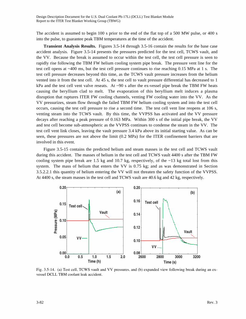
Design Description Document for the U.S. Dual Coolant Pb-17Li (DCLL) Test Blanket ModuleReport to the ITER Test Blanket Working Group (TBWG)
3-82 Rev. 3
The accident is assumed to begin 100 s prior to the end of the flat top of a 500 MW pulse, or 400 s
into the pulse, to guarantee peak TBM temperatures at the time of the accident.
Transient Analysis Results. Figures 3.5-14 through 3.5-16 contain the results for the base case
accident analysis. Figure 3.5-14 presents the pressures predicted for the test cell, TCWS vault, and
the VV. Because the break is assumed to occur within the test cell, the test cell pressure is seen to
rapidly rise following the TBM FW helium cooling system pipe break. The pressure vent line for the
test cell opens at ~400 ms, but the test cell pressure continues to rise reaching 0.15 MPa at 1 s. The
test cell pressure decreases beyond this time, as the TCWS vault pressure increases from the helium
vented into it from the test cell. At 45 s, the test cell to vault pressure differential has decreased to 1
kPa and the test cell vent valve reseats. At ~90 s after the ex-vessel pipe break the TBM FW heats
causing the beryllium clad to melt. The evaporation of this beryllium melt induces a plasma
disruption that ruptures ITER FW cooling channels, venting FW cooling water into the VV. As the
VV pressurizes, steam flow through the failed TBM FW helium cooling system and into the test cell
occurs, causing the test cell pressure to rise a second time. The test cell vent line reopens at 106 s,
venting steam into the TCWS vault. By this time, the VVPSS has activated and the VV pressure
decays after reaching a peak pressure of 0.163 MPa. Within 300 s of the initial pipe break, the VV
and test cell become sub-atmospheric as the VVPSS continues to condense the steam in the VV. The
test cell vent link closes, leaving the vault pressure 3.4 kPa above its initial starting value. As can be
seen, these pressures are not above the limit (0.2 MPa) for the ITER confinement barriers that are
involved in this event.
Figure 3.5-15 contains the predicted helium and steam masses in the test cell and TCWS vault
during this accident. The masses of helium in the test cell and TCWS vault 4400 s after the TBM FW
cooling system pipe break are 1.5 kg and 10.7 kg, respectively, of the ~13 kg total lost from this
system. The mass of helium that enters the VV is 0.75 kg; and as was demonstrated in Section
3.5.2.2.1 this quantity of helium entering the VV will not threaten the safety function of the VVPSS.
At 4400 s, the steam masses in the test cell and TCWS vault are 40.6 kg and 42 kg, respectively.
(b)(a)
0.0 0.5 1.0 1.5 2.0Time (h)
0.00
0.05
0.10
0.15
0.20
Pres
sure
(MPa
)
Test cell
Vault
VV
2600 2800 3000 3200Time (s)
0.08
0.10
0.12
0.14
0.16
0.20
Test cell
Vault
VV
Fig. 3.5-14. (a) Test cell, TCWS vault and VV pressures, and (b) expanded view following break during an ex-vessel DCLL TBM coolant leak accident.

Design Description Document for the U.S. Dual Coolant Pb-17Li (DCLL) Test Blanket ModuleReport to the ITER Test Blanket Working Group (TBWG)
Rev. 3 3-83
(b)(a)
Test cell
Vault
0.0 0.5 1.0 1.5 2.0Time (h)
0
5
10
15
Heliu
m M
ass
(kg)
0
10
20
30
40
50
Stea
m M
ass
(kg)
Test cell
Vault
0.0 0.5 1.0 1.5 2.0Time (h)
Fig. 3.5-15. Test cell and TCWS vault (a) helium masses, and (b) steam masses during an ex-vessel DCLLTBM coolant leak accident.
(b)(a)
0
250
500
750
1000
1250
1500
Tem
pera
ture
(C)
0.0 0.5 1.0 1.5 2.0Time (h)
FW
SW2800 3000 3200
Time (s)
0
500
1000
1500
FW
SW
0
1
2
3FW
Ber
ylliu
m T
hick
ness
(mm
)
FW
0.00
0.05
0.10
0.15
FW Hydrogen Production (kg)
0.0 0.5 1.0 1.5 2.0Time (h)
FW hot strip
Fig. 3.5-16. (a) FW and second wall (SW) temperatures, and (b) FW hydrogen production during an ex-vesselDCLL TBM coolant leak accident.
Figure 3.5-16 presents FW temperature and beryllium oxidation for this accident. The TBM FW
beryllium reaches a temperature of 1278ºC within 90 s of the loss of FW cooling caused by the TBM
helium pipe break. At this temperature, the beryllium evaporation rate disrupts the plasma. Past this
time, the temperature continues to increase due to the beryllium-steam reaction, but once the steam
pressure in the VV starts to decrease this reaction slows and the FW temperature begins to decay. By
4400 s, the FW temperature has dropped to 340ºC. The predicted quantity of hydrogen generated by
the beryllium-steam reaction is 0.15 kg with the “hot strip”, that is the FW region receiving a FW heat
flux of 0.5 MW/m2, losing half of its beryllium. However, 0.15 kg of hydrogen generated is less than
the ITER limit of 2.5 kg for beryllium-steam reactions.
Figures 3.5-17 and 3.5-18 contain results for the first variant case of this accident, which is a
TBM ex-vessel helium leak coupled with an in-vessel Pb-17Li leak. For the most part the results for

Design Description Document for the U.S. Dual Coolant Pb-17Li (DCLL) Test Blanket ModuleReport to the ITER Test Blanket Working Group (TBWG)
3-84 Rev. 3
this variant case are similar to those of the base case. Figures 3.5-17 and 3.5-18 contain those results
that vary between cases. Figure 3.5-17(a) displays the TBM breeder zone pressure for the base case
and this variant case. As was expected, the pressure rapidly decreases as the Pb-17Li is lost from the
TBM through the break that is postulated to occur as a consequence of forces produced by the
induced plasma disruption. Figure 3.5-17(b) presents a comparison between the FW temperature for
the base case and this variant case. As can be seen, the temperatures differ once the Pb-17Li is lost
from the TBM and with it the thermal inertia of this material that keeps the blanket temperatures
higher in the base case. The variant case FW is lower in temperature by ~30ºC by 4400 s after the
occurrence of the ex-vessel leak.
(b)(a)
0.0
1.0
2.0
3.0
Pres
sure
(MPa
)
0.0 0 .5 1.0 1 .5 2.0Time (h)
Base case
Variant case
0.0 0 .5 1.0 1 .5 2.0Time (h)
0
500
1000
1500
Tem
pera
ture
(C)
Base case
Variant case
Fig. 3.5-17. (a) TBM breeder zone pressure, and (b) FW temperature comparisons during a variant ex-vesselDCLL TBM coolant leak accident with a simultaneous in-vessel blanket break.
(b)(a)
PbLi
Vol
ume
(m3 )
0.0
0.1
0.2
0.3
0.4
0.5
0.0 0 .5 1.0 1 .5 2.0Time (h)
TBM system
VV
2800 2825 2850 2875 2900Time (s)
0.10
0.15
0.20
Pres
sure
(MPa
)
Base case
Variant case
Fig. 3.5-18. (a) Pb-17Li volume and (b) VV pressure comparison during a variant ex-vessel DCLL TBMcoolant leak accident with a simultaneous in-vessel blanket break.
Figure 3.5-18(a) gives the volume of the Pb-17Li that is predicted to enter the VV and the volume
that remains in the TBM system during this event. In ~100s, 0.32 m3, or ~2920 kg, of Pb-17Li leaks

Design Description Document for the U.S. Dual Coolant Pb-17Li (DCLL) Test Blanket ModuleReport to the ITER Test Blanket Working Group (TBWG)
Rev. 3 3-85
into the VV. The quantity of hydrogen that would be generated by the ensuring Pb-17Li-water
reaction is ~ 2.5x10⁻⁴ mol-H2/g LM ~ 2.92x10⁶ g LM ~ 2 g-H2/ mol-H2 = 1460 g. The Pb-17Li that
remains in the TBM system resides primarily in the TBM ancillary system, and would only come into
contact with steam. Since the Pb-17Li-steam reaction is fairly benign, and since only 25 g of steam
enters the TBM system during the time analyzed due to the expansion of the accumulator helium
cover gas within this TBM loop, at most only an additional 3 g of hydrogen will be produced. The
result is that the hydrogen generated is less than the ITER allowed limit for Pb-17Li-water reactions
of 2.5 kg. The impact on VV pressure of this hydrogen, the latent heat liberated from the Pb-17Li,
and the 0.75 kg of helium that enters the VV is given in Fig. 3.5-18(b). The maximum VV pressure is
predicted to be 0.175 MPa, which is less than the design limit for this confinement barrier of 0.2 MPa.
Figure 3.5-19 contains results for the second variant case. Figure 3.5-19(a) shows that the test
cell pressure peaks at 0.15 MPa, then decays to 0.102 MPa after ~40 s as a result of the test cell vent
line opening to relieve the pressure in this ITER confinement barrier. The TCWS vault pressure rises
to 0.101 MPa as a consequence of the 5 kg of TBM helium that enters this vault. The resulting peak
pressures are less than the ITER pressure limit for these enclosure of 0.2 MPa. Figure 3.5-19(b) gives
a comparison between the TBM FW predicted for the base case and this variant case. Because the
plasma burn has been terminated by the FPSS, following the low pressure signal from the TBM FW
helium cooling system, the FW temperature immediately drops to 550ºC for this variant case. By
4400 s, the FW temperature will only decay to 540ºC in comparison to the 340ºC value predicted for
the base case. This temperature difference is primarily due to the fact that for the base case an
induced plasma disruption fails the ITER FW, introducing steam into the VV that cools the failed
TBM FW. This steam cooling does not occur in the variant case.
(b)(a)
2790 2800 2810 2820 2830 2840Time (s)
Pres
sure
(MPa
)
0.10
0.12
0.14
0.16
Test cell
Vault
Base case
Variant case
0.0 0.5 1.0 1.5 2.0Time (h)
0
500
1000
1500
Tem
pera
ture
(C)
Fig. 3.5-19. (a) Test cell and TCWS vault pressures and (b) FW temperature comparison with base case duringa variant ex-vessel DCLL TBM coolant leak accident with a simultaneous activation of FPSS.
The long term TBM temperature response for this accident is enveloped by the results presented
in the following section for the TBM loss of active cooling event.
3.5.2.2.4. Complete Loss of TBM Active Cooling
Identification of Causes and Accident Description. This accident can be classified as an
ultimate safety margin event for the TBM (e.g., probability of occurrence < 10-6/a). This accident is a

Design Description Document for the U.S. Dual Coolant Pb-17Li (DCLL) Test Blanket ModuleReport to the ITER Test Blanket Working Group (TBWG)
3-86 Rev. 3
station blackout of at least 10 days duration. The accident has been assumed to occur at the end of the
flat top of a 500 MW ITER pulse. This accident leads to a shutdown of the ITER plasma, and a
complete loss of all active cooling systems for the TBM and ITER-FEAT. As a consequence, the
ITER VV cooling system is assumed to operate in natural circulation mode, maintaining the VV
temperature at 135ºC.
The purpose of this accident analysis is to demonstrate the decay heat removal capability of the
DCLL TBM. This capability must be demonstrated in order to meet ITER safety requirements.
Transient Analysis Results. Figure 3.5-20 shows the TBM FW temperature evolution for this
decay heat removal analysis for two cases. Case 1 is the baseline low-performance design with lower
inlet/outlet LiPb temperatures (340oC/440oC). Case 2 assumes a high performance design where the
inlet/outlet breeder temperatures are 450oC/700oC.
Fig. 3.5-20. DCLL TBM FW temperature evolution due to decay heat during complete loss-of-power event.
In both cases, the FW is initially at 400oC and rapidly increases the temperature due to heat
transfer from the breeder. In the baseline case, the FW temperature reaches a peak of 445oC in about
3 hours and then decreases due to heat transfer to the cooler structures. This peak temperature
increases to 590oC in Case 2, demonstrating the impact initial operating conditions have on predicted
TBM decay heat removal. For comparison, the predicted temperature history for the ITER FW due to
decay heating has been included in Fig. 3.5-20. The ITER curve heats to a peak of ~465oC and then
drops as the decay heat is conducted to the ITER VV and removed by natural convection.
These are positive results for the DCLL TBM in the sense that it shows that the TBM temperature
will remain very close to the operational values during the first few hours of the accident and will
passively decrease below ITER FW values at later times.
3.5.3. Evaluation of Radiological Release
Radiological releases into ITER confinement volumes (e.g., the VV, cell, and TCWS vault)
during the accidents analyzed in the previous section are limited to the mobilizable source terms
called out in Section 3.5.1, which are 150 mg of tritium, 1.8 Ci of Po-210, 36 Ci of Hg-203, and

Design Description Document for the U.S. Dual Coolant Pb-17Li (DCLL) Test Blanket ModuleReport to the ITER Test Blanket Working Group (TBWG)
Rev. 3 3-87
activated F82H oxidation aerosols. The resulting dose if these radioactive source terms were
simultaneously released to the environment would be several orders in magnitude less than the hazard
posed by ITER’s primary radiological source terms. As a consequence, the impact on ITER safety of
these additional sources is negligible.
3.5.4. Uncertainties in Results
There are two primary uncertainties regarding these analyses, which are the validity of the
MELCOR code in simulating such accidents and the ability of the developed MELCOR input model
to accurately simulate the response of the DCLL TBM system. Validation and verification (V&V)
studies for MELCOR in both fusion and fission environments have been extensive and are well
documented by Ref. 3.5-15. In contrast, additional validation of and model development for the TBM
system is required. This validation and model development will be undertaken in the near future
based on results from the two and three-dimensional thermal hydraulic models used in Section 3.2 to
design the DCLL TBM.
There are additional uncertainties regarding the material data base used in the model. However
most of these data come from Ref. 3.5-3, and as such has a safety factor applied to it to ensure
conservative analysis results. However, more oxidation data for the Pb-17Li-water pouring contact
mode will be needed to reduce the uncertainty associated with this reaction and with the hydrogen
generation rate adopted in this safety analysis.
3.5.5. Summary
This assessment of the safety impact on ITER of a DCLL TBM concept shows that the
anticipated radiological inventories are small in comparison to those produced in the ITER VV due to
normal operation of ITER. Possible hydrogen sources were examined in this assessment and the
conclusion was drawn that the maximum quantities produced during accident conditions should be
less than the ITER limit of 2.5 kg. Pressurization of the ITER VV, TBM test cell and TCWS vault by
the helium coolant from the TBM ancillary system does not pose a serious threat to these confinement
structures. Passive decay heat removal is assured, resulting in long term TBM temperatures less than
300oC after 5 days. However, at this time these are preliminary conclusions that are based on
assumptions about the DCLL TBM. More rigorous analyses will be required once more design
details become available for the DCLL TBM concept.
References for Section 3.5
[3.5-1] ITER, "Generic Site Safety Report: Volume VII Appendix A," G 84 RI 6 01-07-10 R 1.0,
July (2004), p. VII 267-292.
[3.5-2] D.V. Andreev et al., "Post-irradiation studies of beryllium reflectors of fission reactor,
examination of gas release, swelling and structure of beryllium under annealing," J. Nucl.
Mater. 244-237 (1996) 880.
[3.5-3] ITER, "Safety Analysis Data List," G 81 RI 10 03-08-08 W 0.1, Version: 4.0.3 SADL,
September 26, 2003.
[3.5-4] D.A. Petti et al., "Safety and Environmental Assessment of ARIES-AT," Fusion Technol. 39
(2001) 449.

Design Description Document for the U.S. Dual Coolant Pb-17Li (DCLL) Test Blanket ModuleReport to the ITER Test Blanket Working Group (TBWG)
3-88 Rev. 3
[3.5-5] M.L. Abbot, L.C. Cadwallader, and D.A. Petti, "Radiological Dose Calculations for Fusion
Facilities," Idaho National Engineering and Environmental Laboratory, INEEL/EXT-03-
00405, April 2003.
[3.5-6] ITER, "Generic Site Safety Report: Volume 1," G 84 RI 1 R 0.2, July (2004), p. I 4.
[3.5-7] K.A. McCarthy, G.R. Smolik, and S.L. Harms, "A Summary and Assessment of Oxidation
Driven Volatility Experiments at the INEL and Their Application to Fusion Reactor Safety
Assessments," Idaho National Engineering and Environmental Laboratory, EGG-FSP-
11193, September, 1994.
[3.5-8] M. Corradini and D.W. Jeppson, "Lithium alloy chemical reactivity with reactor materials:
current state of knowledge," Fusion Engin. and Design 14 (1991) 273.
[3.5-9] D.W. Jeppson, "Fusion reactor breeder material safety compatibility studies," Nucl.
Technol./Fusion 4 (1983) 277.
[3.5-10] Gauntt et al., MELCOR computer code manuals, NUREG/CR-6119, SAND2000-2417/2,
Vol. 2, Rev. 2, version 1.8.5, October 2000.
[3.5-11] B.J. Merrill, R.L. Moore, S.T. Polkinghorne, D.A. Petti, "Modifications to the MELCOR
code for application in fusion accident analysis," Fusion Engin. and Design 51-52 (2000)
555.
[3.5-12] M.J. Gaeta, B.J. Merrill, "CHEMCON User’s Manual Version 3.1," Idaho National
Engineering and Environmental Laboratory, INEL-95/0147 (1995).
[3.5-13] J.R. Welty, C.E. Wicks, R.E. Wilson, Fundamentals of Momentum, Heat and Mass Transfer,
(John Wiley & Sons, Inc., New York, 1969), p. 286.
[3.5-14] M. Iseli, "Safety Criteria for LiPb-He TBM: LiPb Inventory Guideline for He-cooled TBM,"
ITER Draft Memorandum, ITER Garching JWS, January 26 (2005).
[3.5-15] ITER, "Generic Site Safety Report: Volume XI," G 84 RI 10 W 0.2, July (2004), p. XI 16-
25.

Design Description Document for the U.S. Dual Coolant Pb-17Li (DCLL) Test Blanket ModuleReport to the ITER Test Blanket Working Group (TBWG)
Rev. 3 4-1
4. DELIVERY AND REQUIRED R&D PLANS
4.1. TEST PLAN AND REQUIREMENTS
The U.S. strategy for ITER testing of the DCLL concept is flexible and still evolving. The test
plan must remain flexible in order to respond to technical issues that are revealed only during testing,
as well as budget issues that must also be accommodated. The baseline assumption underlying the
current planning and TBWG documentation is:
• For a series of vertical half-port DCLL TBMs,
• With dedicated ancillary equipment systems in transporter casks behind the bioshield and in
space in the TCWS building,
• During the period of the first 10 years of ITER operation.
The strategy for ITER testing progresses from basic structural and MHD performance tests to
more integrated module tests as a function of the ITER operational phases during the first 10 years. It
should be noted that this test program is developed assuming successful testing in previous phases.
An overview of the testing phases is provided in Table 4.1-1.
EM/S TBM: The first test module is an Electromagnetic/Structural (EM/S) module designed to
withstand and measure EM forces and the mechanical response of the TBM structure to such loads
during ITER hydrogen phase operations including: chamber conditioning, startup, shutdown, normal
discharges and transient effects including ELMs and disruption. The EM/S TBM should look like,
and be built from the same FS structural material and using the same fabrication techniques as, more
integrated TBMs in order to validate that structure’s ability to resist disruption loads in particular, and
also measure the effect of the FS on perturbation of the local magnetic fields. The EM/S TBM should
have similar electrical characteristics to more integrated TBMs as well, so that the induced eddy
current and its distributions are simulated. A phased approach proceeding from an empty TBM, to
one filled with frozen metal (possibly a Pb-alloy other than PbLi), stagnant liquid metal and finally
flowing liquid metal is suggested. At the beginning of ITER operation, only a nominal FW coolant
(could even be water) will be required to remove the relatively low surface heat flux coming from the
plasma for pulses of around two hundred seconds. During the H-H phase it is planned to be
continually adding ancillary systems including Helium coolant and PbLi circulations systems and
diagnostic systems, which could be put in operation with the EM/S TBM during the annual
maintenance period. A detailed schedule will need to be developed, but tests of ancillary equipment,
FW cooling, and initial MHD flow tests may be possible during the H-H phase.
NT-TBM: Following the EM/S TBM a Neutronics TBM (NT TBM) will be tested during the D-D
phase and possibly the very beginning of the Low Duty Cycle D-T phases. These neutronics tests can
be performed on a similar “look-alike” structure as the EM/S TBM but clearly we will need the PbLi
itself rather than a surrogate. These dedicated tests aim at examining the present state-of-the-art
neutron cross-section data, various methodologies implemented in transport codes, and system
geometrical modeling as to the accuracy in predicting key neutronics parameters such as
neutron/gamma spectra, tritium production rate (TPR), and nuclear heating rates. The first campaign
in this NT-TBM is quantifying the nuclear field through neutron and gamma spectra measurements.
Multi-foil activation pellets (MFA) can be used for that purpose. The second campaign is for TPR
measurements (can be performed with some techniques such as using lithium glass scintillators for

Design Description Document for the U.S. Dual Coolant Pb-17Li (DCLL) Test Blanket ModuleReport to the ITER Test Blanket Working Group (TBWG)
4-2 Rev. 3
ITER
Yea
r0
12
34
56
78
910
ITER
Ope
ratio
n Ph
ase
Mag
net
test
ing
&va
cuum
• Tor
oida
l Bfie
ld
• FW va
cuum
• Mou
nting
integ
ratio
n
• Mag
netic
pertu
rbat
ion
HH
-Fi
rst
Plas
ma
HH
HH
DD
Low
Dut
yD
T
Low
Dut
yD
T
Low
Dut
yD
T
Hig
h D
uty
DT
• Flue
nce
Accu
mula
tion
Hig
h D
uty
DT
Hig
h D
uty
DT
• Hea
t flu
x• B
Fie
ld• V
acuu
m• D
isru
ptio
ns
• Sm
all
neut
ron
field
• Neu
tron
gam
ma
fluxe
s
• Trit
ium
prod
• Nuc
lear
heat
ing
• MH
D fl
owan
d he
attra
nsfe
r
• Trit
iumpe
rmea
tion
and
rem
oval
• Int
egra
ted
func
tion
• Rad
iatio
nda
mag
e• R
elia
bilit
y
• Be eros
ion
• Dis
rupt
ion
load
s
• Hot
FW
test
• Flo
win
gLM
test
s
• NW
L
• Ful
ldi
srup
tion
ener
gy• L
M fi
lling/
freez
ing/
rem
elt
• Dis
rupt
ion
load
s
• Fin
aliz
eD
esig
n
• Fin
aliz
eD
esig
n
• Fin
aliz
eD
esig
n
Prog
ress
ive
ITER
Test
ing
Cond
ition
s
Elec
trom
agne
tic/
Stru
ctur
al (E
M/S
)TB
M O
pera
tion
Neut
roni
cs (N
T)TB
M O
pera
tion
Ther
mof
luid
/M
HD (T
/M) T
BMO
pera
tion
Inte
grat
ed (I
)TB
M O
pera
tion
Tabl
e 4.
1-1
U.S
. DC
LL
TB
M S
ched
ule
Dur
ing
Firs
t 10
year
s of I
TE
R O
pera
tion

Design Description Document for the U.S. Dual Coolant Pb-17Li (DCLL) Test Blanket ModuleReport to the ITER Test Blanket Working Group (TBWG)
Rev. 3 4-3
detecting TPR from Li-6 and Li-7, lithium foils/pellets, etc.). Fluence requirements for neutronics
tests are shown in Fig. 4.1-1. Generally, all neutronics parameters, except activation and damage
parameters can be measured at one of two fluence levels, namely: low fluence level (~1 W.s/m2).
These levels are the minimum fluence requirements, but higher levels are generally desirable for
improving measuring statistics. The low fluence level could be realized, for example, with a wall load
of 1 MW/m2 and 1-s pulse, or alternatively, a wall load of 0.0025 MW/m2 and 400 s pulse, as is the
case in ITER. Clearly the NWL of ~0.78 MW/m2 at the TBM is much larger than the 0.0025 MW/m2
needed to achieve the required low fluence level for these types of neutronics tests. Therefore, most
of these measurements can be made within the duration of a single pulse. Performing the
measurements of spectra and TBR measurements during the D-D pulses will give information on the
prediction uncertainties under a typical nuclear environment of incident neutrons whose average
energy is ~2.5 MeV. It is therefore desirable to repeat these measurements during the low duty D-T
phase to derive more representative estimates to the prediction uncertainties under a typical fusion
environment. Furthermore, we must have accessibility to reach several locations in the TBM to
perform the aforementioned tests. This can be carried out by inserting two or three radial measuring
tubes in which we place the foils/pellets (in a train) and be able to retrieve them after irradiation from
behind (mechanically, or by a rabbit system) without removing the TBM and/or interrupting the
operation of ITER. Details of this system will have to be designed.
1 mW s/m2 1 W s/m2 ~ 1 kW s/m2 1 MW y/m 2Integral Parameters
Neutron yield NE-213, fission chamber Multifoil Activation (MFA)
Liquid scintillators
Tritium production rate Lithium glass detectors Gas counters
Mass spectroscopy
Proportional counters
Thermoluminescent dosimeter (TLD)
Nuclear heating Gas filled counter TLD Calorimeter
Nuclear reaction rate Fission chamber Activation foil
Mass spectrometry
Neutron and gamma spectrum NE-213, proton recoil MFA
Fig. 4.1-1. Fluence requirements.
T/M TBM: At the beginning of the Low Duty Cycle D-T phase a Thermofluid/MHD (T/M) TBM is
planned. The strategy for the T/M TBM is to allow testing of a variety of flow coolant insert (FCI)
design, geometries and integrated functions. The plan during this period is for moderate temperature
operation of the TBM with PbLi temperature always below the temperature limits of the FS so that
the FCI function can be evaluated safely. Surrogate FCIs using ferritic steel cladding of alumina
insulators may be used in testing if SiC composite FCIs are still under development at that time.
Surrogate FCIs can still be useful to study MHD pressure drop, flow balance and natural convection,
but obviously moving to SiC FCIs at the earliest possible time makes sense in preparing for integrated
TBM experiments to follow. Various geometry and flow conditions will be explored during this

Design Description Document for the U.S. Dual Coolant Pb-17Li (DCLL) Test Blanket ModuleReport to the ITER Test Blanket Working Group (TBWG)
4-4 Rev. 3
period where the goal is to understand and demonstrate the thermal and electrical insulation
properties of the FCI in a lower performance integrated environment, and how these functions may
change over time. The effect of FCIs on tritium permeation at moderate temperature will also be
investigated. A tritium removal system in the PbLi circulation loop is required during this phase to
prepare for the high duty cycle phase to follow. It is noted the MHD tests can proceed even during
dwell periods as the main toroidal field is still present. The rather strong steady toroidal field (~5 T at
the first wall) with prototypic gradients in a large magnetic volume provides in itself a unique
environment for MHD testing probably not available prior to ITER testing. In conjunction with
thermofluid MHD performance, nuclear heating measurements will be performed since this module
will experience the first nuclear heating effects.
I-TBM: During the High Duty Cycle DT phase an Integrated (I) TBM is planned where the longer
term operation of the system is explored including some accumulation of radiation damage in the
FCI, and tritium and transmutation products in the PbLi. SiC composite FCIs should be used at this
time, with operation of the PbLi again at moderate temperature. When confidence is established,
testing of the TBM itself at higher PbLi temperature is desired. This is required to demonstrate the
high temperature capability and potential failure modes. The PbLi flow loop is planned to include a
TBM bypass circuit so that cold-leg PbLi is mixed with the hot PbLi returning from the TBM before
the PbLi proceeds to the ancillary equipment in the hot leg. In this way, the high temperature
operation of the TBM itself can be explored, while the added expense of the high temperature
ancillary systems for heat and tritium extraction can be deferred for testing in later phases of ITER
operation beyond the first 10 years.
4.2. INSTRUMENTATION REQUIREMENTS
Test blanket modules must be diagnosed both to monitor the performance during operation in
order to provide information to the main ITER control systems (sensing for potentially dangerous off-
normal or accident situations) as well as acquire data related to many phenomena being studied by the
specific TBM experiment. Instrumentation includes not just transducers, but any sampling and
conditioning systems needed in order to achieve desired measurements, as well as wiring, conduit,
and feed-through electronic systems, that are compatible at different locations of the TBM system to
the Tokamak environment and during different phases of ITER operation.
Some instrument transducers and measuring systems will need to be embedded in the TBM itself
(T) and must survive in the same fusion environment that the TBM experiences, some instruments
may be located directly behind the TBM (BT), some in the ancillary system in the transporter area
(A), and some in remote locations (R) in the TCWS building and in the tritium processing plant. Each
of these locations has a different environment where diagnostic sensors and wiring insulation must
operate in the conditions as shown in Table 4.2-1.
Line-of-sight view ports to the front of the TBM will be required for visual and IR camera
viewing of the TBM FW surface. Depth markers to indicate the erosion rate of the Be first wall
coating.
It seems likely that all the TBMs and the ITER shield blanket will share many common needs for
basic instrumentation, and any development of such instrumentation specifically for the fusion
environment should be performed in coordination with interested ITER partners and the International
Team. It should also be recognized that while the magnetic field (for instance) will be present from
the beginning of operation, the degree to which other conditions like radiation fields are present will

Design Description Document for the U.S. Dual Coolant Pb-17Li (DCLL) Test Blanket ModuleReport to the ITER Test Blanket Working Group (TBWG)
Rev. 3 4-5
Table 4.2-1
Location of Instrumentations in Response to Different Monitoring and Testing Areas
Monitor and Testing Areas T BT A R
High surface heat flux to the first wall, including auxiliary heating X
Magnetic field of several Tesla, static and transient effects X X X
High power AC EM fields from RF system and plasma fluctuations X X
Induced current and forces during disruptions X X
Acceleration and thermal shocks during disruptions X X
Gamma, beta, alpha, and neutron radiation from plasma and activated
materials
X X X X
High temperature from 300oC to more than 800oC X X X X
High Helium pressure up to 8 MPa X X X X
High Helium speed and possible vibration in Helium channels X X X X
Impurity transport in Helium X X X X
Corrosion by PbLi X X X
Impurity transport and control in PbLi X X X
not be strong until several years after the first plasma, in the DT phases. Similarly, the required heat
removal from the first wall will also be increased gradually. Development of diagnostics should be
synchronized in time with their need in ITER, especially if an extensive development for a given
diagnostic, e.g. robust operation under irradiation, is required. Possible fields to be experimentally
measured in TBMs include:
• Structural resistance, deformations, stress, creep, shocks during disruptions (strain gauges,
displacement sensors, pressure sensors)
• Eddy currents (potential probes, flux coils)
• Temperature (thermocouples, IR pyrometers & cameras, thermistors, RTDs)
• Pressure (piezo, others?)
• PbLi filling/draining, leak detection (ultrasound, RGA, others)
• Helium velocity (flowmeters, hotwire)
• PbLi MHD (potential probes, hall sensors)
• Tritium partial pressure (RGA, mass spec)
• Corrosion by PbLi (mass spec, sample analysis)
• Neutron/Gamma spectra, Tritium production rate (NE213, proton recoil counters)
• Tritium production rates (Li-glass detectors, TLD, Proportional counters, others)
• Nuclear heating (Gas-filled counters, TLD, calorimeters)
Many of the instrumentations being used in operating tokamaks can be considered, with the
added requirement of operating under radiation field.
Selection and integration of suites of diagnostics for individual U.S. TBMs should proceed in
conjunction with more details TBM designs.

Design Description Document for the U.S. Dual Coolant Pb-17Li (DCLL) Test Blanket ModuleReport to the ITER Test Blanket Working Group (TBWG)
4-6 Rev. 3
4.3. R&D PLAN AND REQUIREMENTS
The U.S. pre-ITER DCLL TBM R&D strategy seeks to encourage close collaboration with the
worldwide effort and interest in PbLi systems. Currently, this effort is mostly concentrated in the EU
for the HCLL, but China is beginning work on the PbLi blanket as well. While no agreement has
been formalized, a shared, coordinated and mutually beneficial R&D (including instrumentation
development) and ITER testing program on the HCLL and DCLL is the most productive and cost
effective strategy for developing scientific understanding and technological systems needed for PbLi
breeding blankets. The DCLL concept shares several development issues with the EU-HCLL
concept.
• Ferritic Steel (FS) thermal physical and irradiated properties, production, joining and
fabrication technologies
• PbLi corrosion with FS (EUROFER)
• PbLi chemistry control of corrosion and transmutation products
• Tritium permeation into, and removal from, helium coolants
• Tritium removal from PbLi
• Instrumentation
These are all issues requiring R&D for the HCLL and the DCLL.
The DCLL also has unique issues whose resolution requires both near term R&D as well as a
considered and coordinated testing program in ITER. Circulating PbLi for power removal requires
higher mass flow rates than the HCLL, and magnetohydrodynamic (MHD) effects on flow and
temperature profiles, flow balancing between parallel channels, and pressure drop must be analyzed
in detail. The function of SiCf/SiC as FCI is an integral part of these MHD and thermal
considerations, since flaws and failures of the FCIs will impact the MHD and thermal behavior in
significant ways.
The FCI material (SiC composite or some surrogate) must be fundamentally compatible with
PbLi at high temperature in a dynamic, non-isothermal system with FS structure and ancillary
equipment at lower temperature. The material must be stable in a neutron environment with well
characterized thermophysical properties meeting the needs of the MHD, thermal and tritium
permeation issues cited above.
The DCLL structure with poloidal channels PbLi channels and complex helium flow channels
needs careful design and optimized in order to ensure adequate wall cooling with no “hot” spots
operating above the strength or corrosion limits of the ferritic steel, as well as sufficient strength for
accidental pressurization of the PbLi channels by high pressure helium and for electromagnetic and
thermal loads from normal and off-normal plasma operation, including startup and shutdown.
For a power reactor application, there must also be a goal oriented strategy developed for tritium
and heat extraction from high temperature PbLi, in order to capitalize on the potential for high
efficiency power conversion. The use of FCI as a thermal insulator can be extended into access
piping and heat exchanger shells outside the blanket itself so that FS structure can be used for these
components below its temperature limits. The use of refractory alloys, SiC composite, and corrosion-
barrier-coated super-alloys are all being evaluated for high temperature tritium permeator and heat
exchanger tubes, as are direct contact tritium stripers and heat exchanger technologies. These are

Design Description Document for the U.S. Dual Coolant Pb-17Li (DCLL) Test Blanket ModuleReport to the ITER Test Blanket Working Group (TBWG)
Rev. 3 4-7
presently planned as complementary R&D programs to be implemented in parallel with the ITER
TBM program.
Research into the DCLL concept in the U.S. is proceeding along several avenues:
• Continued design and analysis of TBM including material, thermomechanical, thermal-
hydraulic, neutronics, EM, tritium systems, and safety analyses including documentation for
TBWG.
• MHD and heat transfer analysis of TBM flows in poloidal channels and manifold regions, and
function of FCI as thermal, and electrical insulator. The need for a flow PbLi loop for testing
MHD effects and PbLi compatibility with FCIs is envisioned in the near future.
• SiC composite properties and fabrication techniques including some compatibility experiments
with PbLi in static tests and electrical conductivity measurements.
A detailed planning and costing exercise to determine required R&D and resources needs to bring
the DCLL concept to ITER testing is just now beginning in the U.S. community. During this time as
well, more contacts with the HCLL community in EU and the PbLi development in China are needed,
hopefully leading to an agreement regarding joint development and resource sharing among the
international community interested in PbLi breeder blankets. Finally, the R&D plan aims at
completing the qualification and delivery of the first TBM (either unit cells or submodules) to ITER
one year before ITER installation. This allows one year for port integration tests. On the other hand, it
has been estimated that it may take about 36 months to complete fabrication and testing of a 0.5 m3
module starting from the engineering design. The R&D plan calls for initiating this process about 4
years before the target date of the ITER installation.
4.4. HOT CELL REQUIREMENTS
Test blanket modules (TBM) exposed to the ITER service environment will require post-
irradiation examination (PIE) to assess the condition of the TBM and evaluate the root causes of
unanticipated failures. With progressive testing of different TBMs during different operational
phases of ITER it is essential to perform PIE to gather information on TBM performance so that the
design and fabrication procedures can be modified to achieve greater reliability during succeeding
ITER operational phases, and to project possible performance for DEMO. The capability to handle
highly activated metallic and ceramic components, gases, and liquids will be needed in order to carry
out PIE. The U.S. anticipates the need to recover small exposed sections and possibly specimen
cassettes from the TBM. These cassettes will contain miniaturized test specimens for determining the
integrated effects of the ITER environment on TBM materials. Details of specimen cassettes and
their incorporation into different phases of the DCLL TBM designs need to be determined.
Specimens extensively used in fission reactor irradiation studies to assess mechanical and
microstructural property changes and the corrosive effects of liquid metals and gases will likely be
included. Representative sizes of such specimens are presented in Table 4.4-1.
It is commonly assumed that transportation of an activated TBM back to the country of origin
will not be possible. Therefore, the capability to section the TBM into smaller, more manageable
pieces that can be readily shipped will be needed. It is assumed that facilities to perform detailed PIE
on miniature specimens or on small sections of a TBM will not be available at the ITER site since
each Party already maintains extensive facilities for specimen preparation, examination and testing.
To avoid the expense and difficulty of shipping large radioactive components the main function of the

Design Description Document for the U.S. Dual Coolant Pb-17Li (DCLL) Test Blanket ModuleReport to the ITER Test Blanket Working Group (TBWG)
4-8 Rev. 3
TBM Hot Cell should be to perform optical and other nondestructive examinations, sectioning and
preparation of samples for shipment, diagnostics instrument replacement, extraction of specimen
cassettes, limited repairs and perhaps simple mechanical testing of pre-machined specimens.
Table 4.4-1
Miniature Specimens for Assessing the Effect of the
ITER Service Environment on TBM Design and Materials
Typical Dimensions
Specimen Type
Length
(mm)
Width
(mm)
Thickness
(mm)
Tensile 16 4 0.25
Fracture toughness 12.5 diam — 4.0
Charpy impact 20 1.5 1.5
Bend Bar 18.3 3.4 1.7
DFMB 9 1.7 1.7
Fatigue 16 4 0.25
Creep 25 4.6 diam 0.25
Electron microscopy 3 diam — 0.25
Since it will be difficult to know in every instance how a TBM should be sectioned to recover
pieces for more detailed PIE it is essential that the TBM Hot Cell be equipped to carry out the
following:
1. Remote manipulators for handling the TBM, sections removed from the TBM, and specimen
cassettes.
2. Remote visual inspection and recording to examine and record the condition of the TBM and
sections of a TBM. Such equipment is essential for guiding subsequent cutting operations.
3. Ultrasonic and eddy current nondestructive inspection of the TBM and sections removed from
the TBM.
4. Metrology to characterize dimensional changes with an accuracy of ±1 m.
5. Computer controlled cutting tools such as laser and argon-arc torches, mechanical cropping
equipment and electro discharge machining capability for careful sectioning the TBM and
subcomponents into more manageable pieces.
6. The capability to perform simple mechanical tests such as tensile or Charpy impact testing of
pre-machined specimens over a range of temperatures and possibly under vacuum or inert gas
environment.
7. RF or thermocouple monitoring to track the temperature of the TBM and TBM sections.
8. Radiation monitoring for radioactive decay of the TBM, TBM sections, and test specimens.
9. The capability to load sections of a TBM and test specimens into appropriate activated
material shipping casks for shipment.
Detailed technical parameters and corresponding spatial requirements will need to be specified in
the future. Taking advantage of the hydrogen, DD and then DT operational phases of the ITER
program, the implementation of remotely handled and irradiation tolerant equipment in the TBM Hot
Cell can also be installed in a progression corresponding to the successive phases.

Design Description Document for the U.S. Dual Coolant Pb-17Li (DCLL) Test Blanket ModuleReport to the ITER Test Blanket Working Group (TBWG)
Rev. 3 4-9
ACKNOWLEDGMENTS
This work supported by the U.S. Department of Energy under DE-FC02-04ER54698, DE-FG02-
99ER54313, DE-AC05-76RL01830, DE-FG02-86ER52123, DE-AC07-05ID14517, W-7405-ENG-
48, DE-AC05-00OR22725.


Design Description Document for the U.S. Dual Coolant Pb-17Li (DCLL) Test Blanket ModuleReport to the ITER Test Blanket Working Group (TBWG)
Rev. 3 A-1
APPENDIX A
UPDATED TBM FUNCTIONS AND DESIGN REQUIREMENTS FROM
1997 US-TEST BLANKET PROGRAM [A-1], 1998 EU-HCPB [A-2] AND
1997 EU-WCLL REPORTS [A-3]
1.0 FUNCTIONS AND DESIGN REQUIREMENTS
1.1 FUNCTIONS
The Test Blanket System(s) performs the following functions:
1.1.1. Breed tritium to demonstrate the technical objectives of the test program.
1.1.2. Produce high-grade heat that is removed with a suitable coolant medium to demonstrate the
technical objectives of the test program.
1.1.3. Remove the surface heat flux and the nuclear heating within the allowable temperature or
stress limits.
1.1.4. Reduce the nuclear responses in the vacuum vessel structural material for the ITER fluence
goal.
1.1.5. Protect the superconducting coils, in combination with the vacuum vessel, from excessive
nuclear heating and radiation damage.
1.1.6. Provide a maximum degree of mechanical and structural self-support to: (1) minimize the
loads transmitted to the vacuum vessel, and (2) decouple the operating temperature ranges between
the test blanket system and the vacuum vessel.
1.2. DESIGN REQUIREMENTS
1.2.1. General Requirements
1.2.1.1 The system must be designed for the power requirements set for ITER
a. Nominal Fusion Power 0.5 GW
b. Maximum Fusion Power Excursions +20% of 0.3 MW/m2
c. Burn time/cycle time 400 s per 2000s
d. Average surface heat flux 0.3 MW/m2
10% of the surface heat flux can be 0.5 MW/m2
e. Neutron wall loading 0.78 MW/m2
f. Disruption heat load 0.55 MJ/m2 for 40 ms, 300 cycles per year
g. Duty factor 0.25
1.2.1.2 The primary wall of the Test Blanket shall provide a vacuum tight, cooled barrier between the
plasma and the underlying blanket/shield structure capable of removing the surface heat flux and the
highest level of nuclear heating as specified above.
1.2.1.3 The Test Blanket shall be designed for a FW boundary fluence of 0.3 MW a/m2.

Design Description Document for the U.S. Dual Coolant Pb-17Li (DCLL) Test Blanket ModuleReport to the ITER Test Blanket Working Group (TBWG)
A-2 Rev. 3
1.2.1.4 The Test Blanket System shall demonstrate a tritium breeding ratio sufficiently high to
perform measurements and to allow reliable extrapolation of the breeding ratio to a full size blanket
design.
1.2.1.5 The Test Blanket System shall provide adequate neutron shielding protection to the vacuum
vessel and magnets.
1.2.1.6 The Test Blanket System shall generate high grade heat and remove the heat from the blanket
system with reactor-relevant coolant conditions comparable or higher than PWRs.
1.2.1.7 The Test Blanket System shall be designed for installation, routine maintenance, and removal
by remote handling equipment through horizontal test ports in the cryostat and vacuum vessel. The
time required by these operations shall be minimized.
1.2.1.8 Due to its high level of importance in the successful operation of ITER and its potentially
large effect on the overall machine availability, the Test Blanket System design, R&D, procurement,
manufacture, test, installation, and operation will be to high quality standards.
1.2.1.9 The Test Blanket System will be designed according to the Test Blanket Program standards
and to the applicable codes, manuals, and guidelines specified. The system shall be designed in
compliance with the applicable structural design criteria.
1.2.1.10 System and component reliability requirements are TBD pending outcome of FMEA,
Reliability, and other System Engineering Studies.
1.2.2. Vacuum Requirements
1.2.2.1 A double barrier with intermediate leak detection will be used as the primary tritium
containment boundary at vulnerable locations (i.e. flanges, bellows, etc.). For the Test Blanket
System, this boundary will be established at the nominal Vacuum Vessel.
1.2.2.2 The leak rate inside the primary vacuum must be <10-7 Pa-m3 / sec. The Test Blanket System
should have a leak rate <10-8 Pa-m3 / sec.
1.2.2.3 The Test Blanket System will have to undergo both hot and cold vacuum leak tests.
1.2.2.4 Materials, design, and surface finish must be consistent with the generation and maintenance
of a high quality vacuum and with the ITER outgassing requirements.
1.2.3. Structural Requirements
1.2.3.1 The Test Blanket System shall be designed to withstand stresses in nominal and accidental
situations according to ITER Structural Design Criteria. Details are TBD.
1.2.3.2 The Test Blanket System shall be supported by the vacuum vessel extension and be
cantilevered into its nominal position using an appropriate support structure. It shall be designed to
withstand the following conditions:
1.2.3.2.1 The external pressure inside the vessel will be 10-6 Pa during normal operation, 0.5
MPa for off-normal conditions, and 0.1 MPa for maintenance.
1.2.3.2.2 The helium coolant pressure will be less than:
• Normal operation 10 MPa
• Off-normal conditions TBD MPa
• During system test TBD MPa

Design Description Document for the U.S. Dual Coolant Pb-17Li (DCLL) Test Blanket ModuleReport to the ITER Test Blanket Working Group (TBWG)
Rev. 3 A-3
1.2.3.2.3 Electromagnetic loads as defined in 1.2.4.
1.2.3.2.4 Heat loads at maximum power conditions defined in 1.2.5 and the resulting thermal
stresses.
1.2.3.3 The shield structure must accommodate the loads resulting from the cooling pressure, the
external pressure within the vacuum vessel, and the full range of electromagnetic loads.
1.2.3.4 The Test Blanket System structure must react the range of axisymmetric radial and poloidal
loads on the components that it supports. The weight, net vertical, and net toroidal loads will be
transmitted to the Vacuum Vessel Extension depending on their respective strength.
1.2.4. Electromagnetic Requirements
The system must be designed to withstand the electromagnetic loads resulting from the
interaction of the magnetic fields and eddy current induced in the system during plasma transient
conditions. The combination of these currents and fields existing in the device may result in radial,
toroidal, and / or poloidal pressures on different faces of the modules. The direction and magnitude of
these loads must be determined based on design dependent factors such as: location, electrical
characteristics, size, segmentation, and connection to other components. The loads at all positions
must be calculated for:
a. normal operation, including start-up and shut-down.
b. the system must be designed to withstand a reduced set of electromagnetic induced resulting
from plasma disruptions at 0.55 MJ/m2, duration of 1 ms and 300 cycles per year, and vertical
displacement events (VDE’s) with the parameters described in (ITER design guideline TBD)
and for the number of disruptions specified in (ITER design guideline TBD). Specific values
are TBD.
1.2.5. Thermo-Hydraulic Requirements
1.2.5.1 System Requirements at nominal fusion power of 0.5 GW
1.2.5.1.1 DCLL Design. The blanket is to design to a neutron wall loading of 0.78 MW/m2 and
an average surface heat flux of 0.3 MW/m2. A peak heat flux of 0.5 MW/m2 covering 10% of the
module surface shall be used for the design and lay-out of the first wall and its coolant circuit. The
module will have to be able to withstand transient effects like disruption and VDE as specified by
ITER. The nuclear power deposition distribution shall be specified by 3-D neutronics model
calculations, results are to be used for detail thermalhydraulic calculations and design. Specific
coolant and breeder operating conditions will be selected by the testing objectives of the DCLL TBM
design according to the milestones of development to be further evolved.
1.2.5.1.2 HCPB Design. The thermohydraulic system is designed to remove all the heat
deposited in the proposed test unit cells/submodules. The heat to be removed is 0.1074 MW in the
unit cell option and 0.785 MW if the submodule option is considered. The main coolant is 8 MPa
helium. The coolant inlet and outlet temperature are further guided by the testing objectives. In the
low temperature operational scenario, the inlet and outlet temperatures are set at 100 and 300ºC,
respectively, while in the high temperature operational tests, they are 300 and 500ºC, respectively.
1.2.5.2 System Requirements in off-normal conditions are specified in Heat Loads and Operational
Conditions of the TBM document [A-4].

Design Description Document for the U.S. Dual Coolant Pb-17Li (DCLL) Test Blanket ModuleReport to the ITER Test Blanket Working Group (TBWG)
A-4 Rev. 3
1.2.5.3 The power of the test module shall be iteratively recalculated as the material and specific
TBM design evolve.
1.2.5.4 The Test Blanket System first wall and blanket circuit design will be determined by the
specific blanket option
1.2.5.4.1 DCLL Design. Frist wall and Pb-17 Li breeder zone shall be separately cooled by
independent cooling circuits. The first wall and structure to be cooled by 8 MPa helium coolant. The
breeder zone is cooled by the circulation of Pb-17Li. An over power of 20% and steady state
conditions shall be assumed for the circuit design. The shielding, vacuum vessel, and support
structure will be cooled with a low-temperature helium coolant or a compatible fluid. These coolant
fluids will be preheated by external means to a temperature (300ºC TBD) significantly higher than the
Pb-17Li melting point (235ºC) for keeping the Pb-17Li in liquid form and for material degassing. The
duration of the heating shall be in the order of TBD hours, the test module shall be able to withstand
temperature for degassing and for Pb-17Li fill at least (one TBD) day. The helium coolant circuit
shall be equipped with a control system enabling to keeping the coolant inlet temperatures
approximately constant during the ITER pulsed operation. The high pressure and the chemical
energy of these coolant fluids along with the requirement to isolate and contain tritium-bearing fluids
will require the use of intermediate heat exchangers. These heat exchangers will be located near to
the test port openings, location TBD. The secondary or perhaps tertiary coolant fluids will interface
with the ITER plant systems. The processed tritium streams will interface with the ITER Tritium
Plant.
For the last integrated testing phase of the DCLL TBM program, the module will be designed to
operate at elevated temperature 650oC to demonstrate the generation of high-grade heat. A by-pass
coolant system will be coupled to the heat exchanger to assure that the external circulating Pb-17Li
temperature away from the TBM will not exceed the compatibility temperature limit of 475ºC (TBD)
between the Pb-17Li and FS and the maximum allowable temperature of 550ºC for the FS.
1.2.5.4.2 HCPB Design. The proposed ITER TBM for the helium-cooled solid breeder concept
with FS structure option is not to have US independent ancillary equipments, but rather to have a
partial or complete sharing of other parties’ helium line and auxiliary systems. The main helium
coming from and returning to the TCWS is regulated in the helium coolant conditioning system,
which is equipped with valves, a heater, and a mixer. The system is housed in the piping integration
cask located behind the bioshield plug. The purpose of this coolant conditioning system is to divide
the main coolant into a number of cooling streams and regulate the temperature according to the flow
condition required for sub-units. The proposed unit cell TBM does not have its own first wall
structure. It is housed behind the EU’s FW structural box. In this scheme, a stream of helium of about
0.138 kg/s is extracted from the main coolant and fed to cool the three breeder test units. During the
thermomechanics tests, this coolant will be preheated to a temperature of 350oC (from 300 oC) before
entering into the units. For optional submodule tests, a much larger amount of 8 MPa helium coolant
will be needed (about 0.9 kg/s). The various helium streams from the TBMs will be merged in a
mixer into one stream before it is sent back to the TCWS.
1.2.6. Mechanical Requirements
1.2.6.1 The TBM system including its support structure shall be supported by the vacuum vessel
extension and the be cantilevered into its nominal position using an appropriate support structure.
The corresponding dimensional tolerances and loads (mechanical, thermomechanical and
Design Description Document for the U.S. Dual Coolant Pb-17Li (DCLL) Test Blanket ModuleReport to the ITER Test Blanket Working Group (TBWG)
Rev. 3 A-5
electromagnetical) are TBD. The shield support shall be determined when the TBM support frame,
penetration and TBM transport systems are better defined.
1.2.6.2 The coolant and helium purge lines will be routed through the horizontal test port Vacuum
Vessel ports and will be designed to allow movements during thermal transients.
1.2.6.3 The penetrations of the coolant, breeder, tritium, electrical and diagnostics lines will be
routed through the horizontal ports through the Vacuum Vessel, and will be designed to fulfill all
requirements of a vacuum and safety boundary, and allowing spatial displacement during thermal
transients.
1.2.6.4 Welds that contain water and are in high fluence and / or stress level regions, such as near the
first wall, are subject to stress corrosion cracking and should be avoided.
1.2.6.5 The Test Blanket First Wall shall be bakeable to 240oC.
1.2.6.6 The Test Blanket Articles shall be designed to be removable (RH Class 1) by remote handling
through the horizontal test ports.
1.2.6.7 The Test Blanket structural connections shall use remote handling compatible connectors,
accessible from the back side. The time requirements for this operation shall be minimized.
1.2.7. Electrical Requirements
1.2.7.1 The in-vessel potion of the Test Blanket system shall contribute to meeting the requirement
that the combined toroidal resistance of the blanket in-vessel structures and the Vacuum Vessel must
be larger than 4 . as specified in (GDRD Section 5.3.3.3.1, update TBD)
1.2.7.2 A continuous electrical connection (poloidal and toroidal) between all FW of adjacent
modules is desirable to decrease the above electromagnetic loads at the expense of large localized
effects on these connections.
1.2.7.3 The connection from the tokamak assembly to the outside, through the supply pipes of the
blanket system, shall have a resistance of TBD
1.2.8. Nuclear Requirements
1.2.8.1 The Test Blanket System shall provide enough shielding so that the Vacuum Vessel remains
reweldable at specific locations until an average fluence of 1 MWa / m2 is reached on the FW (Ref.
GDRD 5.5.2.3.3.1, update TBD)
1.2.8.2 The Test Blanket System shall be designed so that the nuclear responses for 0.3 MW a/m2 at
the First Wall are limited to a helium production of < 1 appm at all components behind the shield that
may need to be rewelded, such as Vacuum Vessel, blanket ancillary components, or piping.
1.2.8.3 The blanket system (including the Test Blanket System), in combination with the vacuum
vessel and divertor, shall be designed so that the power dissipated by the attenuated radiation in the
cryogenic toroidal magnet remains within the limits specified in (GDRD Section 5.3.3.6, update
TBD). The peak insulator dose shall be limited to 3x10⁸ rad with 0.3 MWa/m2 at the First Wall.
1.2.8.4 Tritium shall be bred in the test blanket during the DD and DT phases with a tritium breeding
ratio from which the self-sufficiency in a power reactor can be extrapolated. Bred tritium will be
extracted in-situ from the test blankets.

Design Description Document for the U.S. Dual Coolant Pb-17Li (DCLL) Test Blanket ModuleReport to the ITER Test Blanket Working Group (TBWG)
A-6 Rev. 3
1.2.9. Remote Handling Requirements
1.2.9.1 All systems inside the biological shield boundary shall be remotely maintainable. The Test
Blanket System and its supporting subsystems shall be designed in complete compliance with the
remote handling requirements applicable to their respective handling classification. All Test Blanket
System components are to be considered as RH Class 1, except the frames interposing between the
modules and the back plate, which are RH Class 2.
1.2.9.2 The Test Blanket System may be removed and installed without disturbing ITER Blanket/
shield Modules and ITER operation.
1.2.9.3 The Test Blanket System and its supporting ancillary systems inside the shield must be
capable of insertion/removal through the horizontal test ports by fully remote handling.
1.2.9.4 The Test Blanket System and its supporting in-vessel subsystems must be capable of
insertion/removal through the horizontal test ports by use of horizontal test remote handling
equipment.
1.2.9.5 For any maintenance actions, the more important corrective action should meet the following
design goals, see (GDRD Section 5.5.1.3.3.3. and 5.19.3.9.3.1, update TBD)
Test Blanket:
a. be able to replace a module in 4-8 weeks during scheduled maintenance period
b. be able to repair a leak at a fluid joint within 6 weeks
(Not including time required to locate and isolate leak)
1.2.9.6 At prescribed intervals (TBD) and after significant off normal, including electromagnetic,
events it shall be possible, using existing in-vessel inspection equipment, to:
a. inspect/verify modules position
b. inspect/verify First Wall integrity
c. conduct all specified pre-operational tests
1.2.9.7 Special assembly and maintenance tools shall be provided:
a. for structural attachment of the test blanket article to the back plate:
i. for Welded connections:
wall thickness TBD cm
speed:
welding TBD cm / s
cutting TBD cm / s
inspection TBD cm / s
ii. for mechanical connections:
end effectors type and capacity TBD
tools type and capacity TBD
iii. for pipe welding, cutting and inspection of manifolds to blanket module/FW connections;
pipe size 5-50 mm ID (TBD)
wall thickness TBD mm
position from inside pipe

Design Description Document for the U.S. Dual Coolant Pb-17Li (DCLL) Test Blanket ModuleReport to the ITER Test Blanket Working Group (TBWG)
Rev. 3 A-7
speeds:
welding TBD cm / s
cutting TBD cm / s
inspection TBD cm / s
be capable of joining, cutting and leak testing the of the TBM system
iv. others TBD
1.2.9.8 other in-vessel requirements include:
a. Gripping points must be provided on all replaceable components or assemblies capable of
supporting their full weight over the full range of motion required for installation and removal.
b. The structural supports, coolant line joints, instrumentation, and all other interfaces necessary
for (dis)assembly must be compatible with the capability of the remotely operated tools.
c. Sufficient space for the insertion and removal of tools must be assured.
d. All liquid and gas pressure bearing joints must be capable of being leak detected by remote
means.
e. Mechanical guides should be provided to aide the transporter for final positioning and
alignment and to protect adjacent components from damage due to collisions.
f. The maximum mass to be supported by the VV extension shall not exceed TBD kg.
1.2.9.9 Transporter Requirements:
a. The size of the TBM and the transportable supporting and ancillary equipment shall be within
the transporter dimensions. Maximum transported mass is <50,000 kg (TBD.) Afterheat of
(TBD) MW of heat removal capability will be provided by the Transporter, hot cell and /or
storage facility. Active cooling of the test articles will be required during the transport.
Remote surveillance and monitoring may be required (TBD).
b. The transporter shall be designed with adequate flexible for the accommodation and easy
change out of different TBM concepts.
c. The transporter shall be designed to allow intervention or repair in case of the transporter itself
or the transporter equipment fail.
1.2.10. Chemical Requirements
The Test Blanket System and its supporting subsystems must be compatible with the breeder and
coolant chemistry. The chemistry will be specified with the requirement to limit corrosion,
electrochemical, tritium containment and other effects to acceptable levels over the life of the system.
Specifications TBD.
1.2.11. Seismic Requirements
The earthquake resistance of the Test Blanket System and subsystems shall be consistent with the
specifications adopted for the ITER building. The Test Blanket System shall in particular contribute
to the efficient confinement of radioactive material and chemicals during an earthquake so that the
allowable release will not be exceeded.

Design Description Document for the U.S. Dual Coolant Pb-17Li (DCLL) Test Blanket ModuleReport to the ITER Test Blanket Working Group (TBWG)
A-8 Rev. 3
1.2.12. Manufacturing Requirements
The TBM shall be manufactured according to the RCC-MR code class 1 (TBD) with particular
emphasis on tolerances between the TBM and interface frame as well as between interface frame and
shielding blanket in the following situations:
a. installation and shut-down after operation;
b. nominal operation taking into account the pulsed conditions and irradiation effects (e.g.
swelling) on ITER blanket, interface frame and TBM;
c. accidental situations which could lead to deformations of the TBM or its surroundings;
The manufacture of the test blanket system shall be accompanied by an approved quality
assurance plan and pass an acceptance test prior to installation. (Other testing requirements see
1.2.15). These acceptance tests are TBD but shall include among others:
• Pressure and flow testing of all fluid channels
• Vacuum leak testing
• NDT certification of structural welds
• Certification of bonding of dissimilar melts
• Certification of critical dimensions
1.2.13. Construction Requirements
Construction requirements are TBD; however it is anticipated that specific requirements will be
applied to the transportation, handling, and storing of the various components of the TBM system.
1.2.14. Assembly Requirements
1.2.14.1 The alignment of the Test Blanket First Wall to the magnetic surface of the shielding
blanket is TBD. At the equatorial level, a maximum recess of 50 mm with respect to the magnetic
surface of the primary first wall can be used for the first wall of the test blanket.
1.2.14.2 The Test Blanket will also have the requirement (TBD) to minimize any gap to adjacent
modules in order to minimize neutron streaming.
1.2.14.3 The Test Blanket System shall be installed from the horizontal test ports using remote
handling equipment. The structural support element for the blanket portion of the Test Blanket
System shall be attached to the Shielding Blanket Backplate by bolting or welding. Provisions are to
be provided to react to all design basis loads.
1.2.14.4 The shielding and vacuum vessel portion of the Test Blanket System shall attach to the
nominal Vacuum Vessel.
1.2.14.5 All assembly techniques must be compatible with maintaining the vacuum requirements on
the system. Handling, cleaning, limits on the use of potential contaminants, etc. must be in
compliance with the vacuum specifications.
1.2.15. Testing Requirements
1.2.15.1 The Test Blanket System must pass both a hot and cold leak test after completion of its
assembly within the vacuum vessel and prior to start of operation. This will supplement the Test
Blanket System full operational test in the Hot Cell prior to installation on the ITER device.

Design Description Document for the U.S. Dual Coolant Pb-17Li (DCLL) Test Blanket ModuleReport to the ITER Test Blanket Working Group (TBWG)
Rev. 3 A-9
Cold leak tests
a. Internal pressure TBD MPa w/helium
b. External pressure 1 Pa
c. Component temperature 20oC/300ºC (TBD)
d. Total leak rate acceptance level 1x10⁻⁸ Pa m3/s
Hot leak tests
a. Internal pressure TBD MPa w/helium
b. External pressure 1 Pa
c. Component temperature 200-700oC (TBD)
d. Total leak rate acceptance level 1x10⁻⁸ Pa m3/s
1.2.15.2 The system must be pressure tested with operational coolant according to the applicable
rules for pressure vessels after welding of the shield and first wall coolant connections to their
respective manifolds. Each flow circuit must be flow tested to demonstrate the required flow rate at
the design pressure differential.
1.2.16. Instrumentation & Control Requirements
1.2.16.1 The instrumentation (number and location TBD) of the breeder and cooling circuits shall
include:
1.2.16.1.1 DCLL design
• pressure (absolute pressure and pressure drops)
• temperature (at various locations in the Test Blanket system)
• radioactivity in primary and secondary coolant and Pb-17Li
• hydrogen isotope concentration (protium, deuterium, tritium in primary and secondary
cooling water and Pb-17Li)
• mass flow-rates in coolant and Pb-17Li
• tritium concentration in Pb-17Li
• gas detection in Pb-17Li
• level (water and Pb-17Li)
• neutron detector in test blanket
• scan wires in test blanket
• surveillance of component integrity (TBD)
• leak detection
• positioning and deformation
• stress
• others (TBD)
1.2.16.1.2 HCPB design
• pressure gauges (absolute pressure and differential pressure gauges)
• thermocouples (at various locations in the test blanket units and auxiliary systems)
• tritium measurement system
• flow meter

Design Description Document for the U.S. Dual Coolant Pb-17Li (DCLL) Test Blanket ModuleReport to the ITER Test Blanket Working Group (TBWG)
A-10 Rev. 3
• neutron detector in test blanket
• scan wires in test blanket
• strain gauges inside the test blanket units
• others (TBD)
1.2.16.2 Redundant control systems are required for flow rate, temperature and pressure control in the
breeder and coolant circuits. Details are TBD.
1.2.16.3 A data acquisition system shall process the measurement values and shall issue alarm
messages in case of abnormal indications (TBD) which shall lead to reactor shut-down in case of
confirmed abnormal behaviour. The response time between the detection of an abnormal event and
reactor shut-down (< TBD sec) shall be optimized. The development of a licensed safety strategy is
TBD.
1.2.17. Decommissioning Requirements
The system shall be designed to minimize the disposal rating. Since the rating criteria are site
specific, the specific criteria are TBD.
1.2.18. Electrical Connections/Earthing / Insulation Requirements
The grounding requirements are TBD.
1.2.19. Material Requirements
1.2.19.1 The materials of the in-vessel components will be chosen according to the test blanket
requirements, the compatibility between materials, and their outgassing requirements and to the
physics requirements with the objective of limiting the impurity level inside the machine.
1.2.19.2 The materials of the in-vessel components have to be consistent with the generation and
maintenance of a high quality vacuum.
1.2.19.3 Materials shall be used with well characterized mechanical, structural and irradiation
properties for their respective service conditions (temperature, stress, irradiation, hydrogen etc.) in
order to obtain a high degree of confidence in their performance capability.
1.2.19.3.1 The materials used in the DCLL test blanket are anticipated to be:
Table 1.2.19-1
Summary of Structural Material Requirements
Structural material 9% Cr martensitic steel (grade is TBD)
First wall structural material 9% Cr martensitic steel (grade is TBD)
First wall protection Be (form and attachment are TBD)
Breeder material Pb-17Li, 6Li enrichment 90%
Flow coolant insert SiC-composite
Shielding stainless steel (water cooled)
First wall and structure coolant 8 MPa helium
Piping 9% Cr martensitic steel for in-vessel components (grade is TBD),
stainless steel for other ancillary equipment

Design Description Document for the U.S. Dual Coolant Pb-17Li (DCLL) Test Blanket ModuleReport to the ITER Test Blanket Working Group (TBWG)
Rev. 3 A-11
1.2.19.3.2 The materials used in the PCPB test blanket are anticipated to be:
Table 1.2.19-2
Summary of Structural Material Requirements
Structural material 9% Cr martensitic steel (grade is TBD)
First wall structural material 9% Cr martensitic steel (grade is TBD)
First wall protection 2 mm Be (form and attachment are TBD)
Breeder material Li4SiO4 or Li2TiO3 pebbles (TBD)
Neutron multiplier Be pebbles
Shielding stainless steel (water cooled)
First wall and structure coolant 8 MPa helium
Piping 9% Cr martensitic steel for in-vessel components (grade is TBD),
stainless steel for other ancillary equipment
1.2.20. HVAX Requirements
Not directly applicable
1.2.21. Layout Requirements
1.2.21.1 Structural and leak tightness welds shall be removed as far away as possible from high
neutron flux locations.
1.2.21.2 Welds shall be isolated from gaps whenever possible. Field welds shall be protected by
sufficient shielding to allow rewelding.
1.2.21.3 The main coolant headers shall be minimum of TBD cm diameter with TBD minimum bend
radius everywhere along the required traveling route of in-pipe welding equipment to be determined
by the method and approach of cutting/welding.
1.2.21.4 Special attention shall be given to gaps between modules. Radiation streaming shall be
minimized by design.
1.2.21.5 The Test Blanket System shall be sized for insertion and removal through the horizontal
mid-plane test port and the transporter shall be sized to accommodate the Test Blanket System and
corresponding ancillary equipment.
1.2.21.6 Wherever structural welding is required, the module arrangement shall include a (TBD) mm
space adjacent to welds for remote welding/cutting equipment. This layout must include an
unobstructed route, of this corss-sectional size, between the weld and the point of entry for the
welding equipment. Welding and cutting of the coolant manifolds may be from the interior of the
pipes.
1.2.21.7 The Test Blanket System shall be designed to be safely drained of all liquids.
1.2.22. Safety Requirements
The safety requirements for the Test Blanket System are derived from the General Safety and
Environmental Design Criteria (GSEDC), the General Design Requirements Document (GDRD) and
functional safety requirements (confinement, fusion power shutdown, decay heat removal,
Design Description Document for the U.S. Dual Coolant Pb-17Li (DCLL) Test Blanket ModuleReport to the ITER Test Blanket Working Group (TBWG)
A-12 Rev. 3
monitoring, and control of chemical energies) which are generally necessary for ITER. All criteria
and requirements build upon the fundamental safety principles stated below:
• Design, construction, operation and decommissioning shall meet technology-independent
radiological dose and radioactivity release limits for the public and site personnel based on
recommendations by international bodies such as IAEA and ICRP.
• During normal operation, including maintenance and decommissioning, radiation exposure of
site personnel and the public shall remain below the prescribed limits and be kept as low as
reasonably achievable (ALARA).
• ITER shall make maximum use of favorable safety characteristics which are inherent to
fusion. Uncertainties of plasma physics shall not have an effect on public safety.
• The defense in depth concept shall be applied to all safety activities so that multiple levels of
protection are provided to prevent or minimize the consequences of accidents.
• Special attention should be given to passive safety.
• The design shall minimize the amounts of radioactive and toxic materials and the hazards
associated with their handling.
• All conventional (non-nuclear) safety and environmental impacts from construction, operation,
and decommissioning shall meet common industrial standards for industrial practice. This
includes chemical toxins and electromagnetic hazards.
1.2.22.1 Safety Functions. The Test Blanket System may contain ‘experimental’ components to
which no safety function will be assigned. The Test Blanket System may, however, support the
safety function ‘fusion power shutdown’ in off-normal situations by passive or active action;
however, the definition of and requirements on this type of system depend on the TBM behavior in
off normal conditions and are treated in Section 3.5 (Safety Analysis)..
1.2.22.2 Safety Classification of Items. The Test Blanket System equipment shall be classified
according to its importance to safety into four classes according to Table 4.1.2.-3 “Safety Importance
Classification” in [GDRD – Safety v.5 (4/21/95)] and the associated rules. The following provisional
Safety Importance Classes (SIC) are suggested by the Environmental and Health Division (SEHD):
Component SIC Comment
In-vessel part of the Test Blanket System 3 or 4 TBD No design and related safety
analyses are presently available
Ex-vessel part of the Test Blanket System
and blanket coolant loops
2 SIC-2 for confinement
SIC-4 for decay heat removal
1.2.22.3 Safety Design Limits and Analysis Requirements. The safety limits shall be determined by
iterating deterministic and probabilistic safety analysis with the design of the Test Blanket System.
The safety analyses shall use the process adopted by the project which aims at systematic
identification, modeling, and analysis of the representative event sequences. Depending on the
required degree of detail, this process will be graded from qualitative analysis up to detailed
simulations and calculations. Accident initiating events will be identified through Failure Modes and
Effects Analysis (FMEA) and then grouped in Postulated Initiating Event (PIE) categories. The PIEs
will be supplemented by the related accident source terms (tritium, activation products), determined

Design Description Document for the U.S. Dual Coolant Pb-17Li (DCLL) Test Blanket ModuleReport to the ITER Test Blanket Working Group (TBWG)
Rev. 3 A-13
in a conservative manner. Particularly, detailed fault analysis shall be performed where there is
potential for challenging confinement barriers.
Provisional safety design limits are as follows:
• Because beryllium (Be) is used as FW armor material, short term temperatures shall stay
below 800oC (TBD) to avoid Be-steam ignition scenarios.
• Long term (decay heat driven) Be FW armor material temperatures shall be limited to 500oC
(TBD) to avoid excessive H2 production.
• The maximum allowable H2 production inside the Vacuum Vessel is 5 kg (TBD).
• Maximum steel temperatures are TBD and depend on the final material choice. Environmental
effects (e.g. DBTT or hydrogen embrittlement) shall be accounted for.
• The inventory of Be dust inside the vacuum vessel shall be limited to 100 kg (TBD). This
value is provided provisionally for ease of EDA design.
• The total mobilizable tritium inventory inside the PFCs (first wall, divertor, limiters,
launchers) shall be limited to 1 kg.
• The corrosion products in the blanket cooling loops shall be limited to a total of 10 kg (TBD).
• The tritium concentration in the water cooling loops, resulting from coolant activation,
permeation through surfaces or leakage, shall stay below 1 Ci/kg.
The consequences for the TBM are TBD.
1.2.22.4 Safety Assessment. The safety analyses will include but are not limited to the following
events (cf. Section 3.5 Safety Analysis):
• Plasma disturbances (such as disruptions, VDEs, power excursions) resulting in an overload of
the TBM.
• Over-pressure in the VV from water LOCAs causing steam formation and H2 generation on
hot TBM FW armor surfaces.
• Temperature/pressure transients of the Test Blanket due to LOFAs or in-/ex-vessel LOCAs in
one or both primary heat transfer systems and from in- and ex-vessel LOCAs with eventual
chemical interaction between water and Pb-17Li.
• Pressure and temperature transients with related chemical reactions inside the TBM due to
water ingress by LOCAs.
• Pressure and temperature transients and related chemical reactions at the FW surface due to air
or water ingress into the VV.
• Loss of Heat Sink Accident in one or both cooling circuits
• Loss of Heating Event with undesired solidification of Pb-17Li.
• Loss of Breeder Material Event and related chemical reactions at the FW surface or elsewhere
due to Pb-17Li ingress into the VV.
• Mechanical loads to the TBM from magnet accidents and disruptions.
• Others (TBD)
1.2.22.5 Test Blanket System Safety Requirements
1.2.22.5.1 The design basis for the Test Blanket System shall take into account the initiating
events and potential loads due to accidents as identified by the safety analysis (cf. Section 3.5).

Design Description Document for the U.S. Dual Coolant Pb-17Li (DCLL) Test Blanket ModuleReport to the ITER Test Blanket Working Group (TBWG)
A-14 Rev. 3
1.2.22.5.2 The design of the blanket module support structure shall react a large portion of the
load acting on the modules thus minimizing the load on the Vacuum Vessel, the first radioactivity
confinement barrier.
1.2.22.5.3 The Test Blanket System shall not significantly contribute to the ITER radioactivity
source term and the blanket parameters shall be chosen accordingly.
1.2.22.5.4 The design should minimize the volume of liquid spills from the Test Blanket article
into the Vacuum Vessel.
1.2.22.5.5 The temperature limits specified in 1.2.22.3 shall be respected by an appropriate design
to avoid in-vessel LOCA with the related concerns (radioactivity release, hydrogen production). For
this purpose, the cooling circuits for the First Wall and the Breeder Zone shall be separate and
independent, each ensuring the cooling of the complete Test Blanket article from an accidental
situation to a stable and safe condition. Redundancy/diversity/spatial separation of cooling circuits
and components are TBD and a trade-off between component reliability and system availability.
1.2.22.5.6 The design should limit the long term (several hours after shutdown) decay heat driven
FW temperatures to avoid H2 concentrations in the Vacuum Vessel which are prone to
deflagration/detonation if air ingress in the Vacuum Vessel cannot be excluded.
1.2.22.5.7 The cooling loops are segmented into two independent systems (redundancy, diversity,
spatial separation are TBD), see also 2.2.1.
1.2.22.5.8 Attention should be paid to potentially asymmetric temperature distributions due to
these measures which should not cause thermal stress in the first wall/blanket equipment above
permissible limits.
1.2.22.5.9 Off-normal heat removal should be as passive as possible. The envisaged heat-
exchanger location in the pit area limits, however, the possibilities for decay heat removal by natural
coolant circulation. It is suggested further to increase by adequate surface treatment (selective
coatings), if the vacuum requirements allow, the relative emissivity of thermal radiation between the
adjacent surfaces of Test Blanket System and Vacuum Vessel to values significantly above the
natural ones (such as 0.8 vs. 0.3).
1.2.22.5.10 In general, the design should limit:
• the inventory of radioactive, chemically reactive, or toxic dust inside the Vacuum Vessel
• the mobilizable tritium inventory inside the Test Blanket System
• the corrosion products in the Test Blanket System cooling loops
• the tritium concentration in the Test Blanket System coolant system
• the activation products in involved materials
• the toxicity of the involved materials or derivatives formed during an accident
• the chemical energy release potential
• the physical energy release potential
1.2.22.5.11 Monitoring shall be provided to indicate whether the above requirements are being
met.
1.2.22.5.12 The design of decontamination, shielding, remote operation, flask transfer functions
should minimize the dose to personnel in the course of maintenance and decommissioning.

Design Description Document for the U.S. Dual Coolant Pb-17Li (DCLL) Test Blanket ModuleReport to the ITER Test Blanket Working Group (TBWG)
Rev. 3 A-15
1.2.22.5.13 Amounts and radio-toxicity of radioactive waste from operation and
decommissioning of the Test Blanket System equipment should be minimized within the limits set by
the applicable material.
1.2.22.5.14 The experimental nature of the FW leads to the design requirement for the Vacuum
Vessel that failures of the FW should not cause rupture of the vessel which is the first radioactivity
confinement barrier.
1.2.22.5.15 Other Requirements
1.2.23. Interfaces Requirements (e.g., with frame, port cell, TWCS vault, transporters, hot cell,etc.)
In order to successfully complete all test objectives, the Test Blanket System must work in
cooperation with many of the other ITER systems and facilities. These interrelationships are many
and complex, involving both geometric and functional requirements. The system interfaces are
described in Section 1.2.30.
1.2.24. Other Requirements (R&D, maintenance, inspection, code & standard, reliability, etc...)
1.2.24.1 R&D Requirements. Several aspects of the Test Blanket System require special
development, demonstrations, or testing in order to adequately assure that the design satisfies system
requirements. The R&D programs will be necessary to: (1) support the blanket system design by
confirming its basic viability, influencing the design details in critical areas, determining irradiated
and non-irradiated material properties; and (2) to help determine detail design and fabrication
parameters, procedures, and specifications. Key design inputs required from the R&D program are:
1.2.24.1.1 DCLL R&D Requirements (Included in Section 4.3)
1.2.24.1.2 HCPB R&D Requirements (Included in HCPB DDD Section 4.1)
1.2.25. Operation and Maintenance
The operational and maintenance requirements for the Test Blanket System are included in
Section 1.2.1 and 1.2.9.
1.2.26. Surveillance and In-Service Inspection
The surveillance and in-service inspection requirements are included in Section 1.2.9.
1.2.27. Quality Assurance
The quality assurance requirements are included in Section 1.2.1.
1.2.28. System Configuration & Essential Features
The configuration and essential features are included in Section 1.2.21
1.2.29. Codes and Standards
Codes and standards requirements are included in Section 1.2.1. The ITER Structural Design
Code shall be used wherever applicable.

Design Description Document for the U.S. Dual Coolant Pb-17Li (DCLL) Test Blanket ModuleReport to the ITER Test Blanket Working Group (TBWG)
A-16 Rev. 3
1.2.30. Interfacing Systems
In order to successfully complete all test objectives, the Test Blanket System must work in
cooperation with many of the other ITER systems and facilities. These interrelationships are many
and complex, involving both geometric and functional requirements. Below is a list of the systems
that have a significant impact on the operational capability of the Test Blanket System. A brief
description of the geometric and functional requirements are given to each interfacing system. In the
future, a set of interface control documents will be prepared to identify the complete listing of
interfaces and define the detailed requirements of each interface.
1.2.30.1 Vacuum Vessel. The Vacuum Vessel System is to provide twenty horizontal ports for
systems to access the plasma chamber. Specifically, this involves ports or access chambers of a
particular size and structural capability to properly accommodate the port systems, including ancillary
equipment, and the associated remote handling equipment.
The unique requirements imposed by the Test Blanket System will involve the mounting
configuration onto the Vacuum Vessel Wall, the structural requirements during operation and
maintenance periods, the thermal conditions of the shield and ancillary equipment, and
accommodations for routing of plumbing lines.
• Number of Test Ports Required
• Horizontal port size / geometry
• Load support requirement
• Thermal requirements
• Coolant plumbing requirements
— Size / Location
— Mechanical loads and displacements
— Special Seal requirements
— Penetration requirements
Shielding Blanket. The Test Blanket System will work in close cooperation with this system.
One of the primary requirements for the Shielding Blanket is to support the static and dynamic loads
of the Test Blanket First Wall and Blanket portion of the Test System. This support will be provided
by the Shielding Blanket Backplate. To support the imposed loading conditions, the Backplate will
have to be strengthened to provide additional support. The Backplate will also have to provide
provisions to handle the to-be-specified shear loads (e.g. shear keys).
There must be a high level of geometric synergism between these two systems to meet the ITER
gap requirements for neutronic streaming and not have contact load transfer between systems
modules.
In order to provide limited protection from direct plasma ion impingement on the test blanket first
wall, the Test Blanket shall be recessed below the general surface level of the surrounding Shielding
Blanket First Wall. This will impose additional surface heating requirements on the adjacent
Shielding Blanket First Wall components. The temperatures and surface conditions (emissivity,
absorptivity, and surface area) of the interfacing surfaces will have to be determined to estimate the
anticipated heat transfer.
• Geometry
• Mechanical Loads

Design Description Document for the U.S. Dual Coolant Pb-17Li (DCLL) Test Blanket ModuleReport to the ITER Test Blanket Working Group (TBWG)
Rev. 3 A-17
• Physical Properties
• Thermal Loads
1.2.30.2 Remote Handling Equipment. Remote handling equipment will be required to install,
inspect, and maintain diagnostic, plasma heating, maintenance, test blanket modules, and shield port
systems through the horizontal access ports. The specific interface requirements for the Test Blanket
System will involve unique geometry, weight, positioning, and thermal constraints. The geometry
will involve not only the Test Blanket, which may be separated into two elements, but will also
include the ancillary equipment that will be positioned behind the blanket in the Vacuum Vessel
Extension area. Special-use and effectors will be the responsibility of the Test Blanket System.
Some of the interface requirements are listed below:
• Maximum supported weight
• Positioning accuracy
• Kinematics requirements
• Inspection requirements
• Accommodation of special end effectors
• Accommodation of special materials and coolants
1.2.30.3 Cryostat. The Cryostat System is to provide twenty horizontal ports for access to the
Vacuum Chamber. Additionally, the Cryostat is to provide the Second Tokamak Confinement
Boundary.
The unique requirements imposed by the Test Blanket System will involve the unique geometry
constraints and special maintenance requirements. Plumbing lines shall be accommodated in the port
areas.
• Number of test ports required
• Horizontal port size / geometry
• Thermal requirements
• Coolant plumbing requirements
— Size / location
— Mechanical loads and displacements
— Special seal requirements
— Penetration requirements
1.2.30.4 Primary Heat Transport System. This system is to provide water coolant to remove the heat
generated in the test blanket and shield. Detailed information needed;
• Number of loops
• Inlet and outlet temperature for each loop
• Flow rate for each loop
1.2.30.5 Vacuum Pumping System. The blanket system is partially contained within the primary
vacuum boundary and affects the volume pumped by the Vacuum Pumping System. As a result,
emissions from surfaces and leaks from the blanket system must be within the capability of the
pumping system. In addition, the vacuum pumping may include specific components, such as tracer
gas sources, for remote leak checking. These components must be permanently mounted on the
blanket components near high potential leak sources.

Design Description Document for the U.S. Dual Coolant Pb-17Li (DCLL) Test Blanket ModuleReport to the ITER Test Blanket Working Group (TBWG)
A-18 Rev. 3
• Outgassing requirement
• Leakage Rate
1.2.30.6 Tritium Plant. The use of unique materials will affect the Tritium Plant System involving the
possible airborne elements.
1.2.30.7 Tokamak Operations and Control. The Test Blanket System instrumentation needs shall be
integrated into the Tokamak Operations and Control System.
1.2.30.8 Building. The building space external to the cryostat and biological shield shall
accommodate the Test Blanket System maintenance scheme. Space and support services shall be
provided for operational support equipment near the horizontal test ports. Radial space must be
provided to remove the modules from the mid-plane maintenance ports and transport them to the hot
cells.
• Location and size of needed space
• Support services (electrical, I&C fluids)
Waste Treatment and Storage. The Test Blanket System will impose some additional requirements
on the Waste Treatment and Storage System. This will evolve from the use of unique materials (see
Section 1.2.19) and coolants.
1.2.30.9 General Testing Equipment. The Test Blanket System will impose some additional
requirements on the General Testing Equipment System. This will evolve from the use of unique
materials (see Section 1.2.19) and coolants.
Codes and standards requirements are included in Section 1.2.1.
Reliability requirements are included in Section 1.2.1
1.2.31. Other Special Requirements
1.2.31.1 Both the cooling and the breeder circuits are expected to contain tritium (from both breeding
and permeation) as well as activation products. Purification (on-line or batch) is foreseen for both
circuits. A suitable confinement of the ancillary circuits is therefore required to meet safety and
maintenance requirements.
1.2.31.2 Guard heating of the complete Pb-17Li circuit to keep the liquid metal liquid. A moderate
increase in melting point (due to Li depletion by Pb-17Li/water interaction) should be taken into
account for the dimensioning.
1.2.31.3 The Pb-17Li and the coolant circuits shall be thermally insulated against their environment
and comply with the requirements of the areas they penetrate (e.g. vacuum, impurities).
1.2.31.4 Tritium carrying fluids shall have a double confinement with leak detection from the TBM to
the circuit caissons (TBD).
1.2.31.5 Other Requirements are TBD

Design Description Document for the U.S. Dual Coolant Pb-17Li (DCLL) Test Blanket ModuleReport to the ITER Test Blanket Working Group (TBWG)
Rev. 3 A-19
References for Appendix A
[A-1] U.S. Contribution to Test Blanket Program, Draft ITER Test Blanket Program GDRD Test
Blanket System DDD, U.S. Proposal on Solid Breeder Blanket Test Program, Test Program
Proposal for U.S. Liquid Breeder (Li/V) and U.S. Proposal on Neutronics Test, UCLA-FNT-
132, October 1995.
[A-2] European Helium Cooled Pebble Bed (HCPB) Test Blanket, ITER Design Description
Document Status, 1.12.1998, Forschungszentrum Karlsruhe, FZKA 6127, 1999.
[A-3] European Water Cooled PbLi (WCLL) Test Blanket, 1997. Personal communication from
Dr. Yves Poitevin of EFDA.
[A-4] Heat Loads and Operational Conditions of the Test Blanket Modules (TBM), by K. Ioki,
TBWG meeting, 9-11 March 2004.


Design Description Document for the U.S. Dual Coolant Pb-17Li (DCLL) Test Blanket ModuleReport to the ITER Test Blanket Working Group (TBWG)
Rev. 3 B-1
APPENDIX B
ITER DCLL TBM CALCULATION SHEETS
Note: The following heat exchanger flow sheet is shown with earlier results with helium Tin at 440oC
and Tout at 380oC, where the updated design has helium Tin at 460oC and Tout at 380oC, due to the
increase in TBM module frontal area and therefore power input, the corresponding helium mass flow
rates are maintained to be similar. Therefore, the heat exchanger area will be larger, but not by too
much and the basic parameters should not be very different between the earlier and updated designs.
In the future, heat exchanger designs will be re-visited.

Design Description Document for the U.S. Dual Coolant Pb-17Li (DCLL) Test Blanket ModuleReport to the ITER Test Blanket Working Group (TBWG)
B-2 Rev. 3
Table B-1
Summary of FW-Loop Helium to Water Heat Exchanger Design
ITER
Calculation By: D. P. Carosella
General Atomics
Calculation Sheet System ITER Test LoopTitle: "U" Tube Helium Heat Exchanger Design Cold Aluminum
Page No.: 41
Calculation No.: 1
IV. RESULTS:
Summary of Design Data for the Helium to Water Heat Exchanger:
Metric English
Heat Duty: Qhex 569.2kW� Qhex 1.942 106
� BTU hr1�
�
�
�
Effectiveness/NTU: eff 0.148� / NTU 0.162�
Design Uncertainty UNht 15%�
Water Data :
Flow Rate: WH2O 16.99kg sec1�
�
�
� WH2O 37.47 lbsec-1
�
Inlet Temperature: TCH2Oin 35C� TFH2Oin 95F�
Outlet Temperature: TCH2Oout 43C� TFH2Oout 109.4F�
Pressure Drop: �PH2O 0.0287MPa� �PH2O 4.162psi�
Percent Pressure Drop:�PH2O
PH2Omax2.87%�
Pumping Power PPH2O 491.02watt� PPH2O 0.658hp�
Maximum Velocity: VelH2Omax 1.73m
sec� VelH2Omax 5.68ftsec
-1�
Saturation Temperature: TCSAT 179.9C� TFSAT 355.8F�
Helium Data:
Flow Rate: WHe 1.82kg sec1�
�
�
� WHe 4.02lbsec-1
�
Inlet Temperature: TCHein 440C� TFHein 824F�
Outlet Temperature: TCHeout 380C� TFHeout 716F�
Pressure Drop: �Ptot 0.044MPa� �Ptot 6.43psi�
Percent Pressure Drop�Ptot
PHe0.55%�
Pumping Power: PPHe 14.35kW� PPHe 19.24hp�
Tube Wall Temperature: TCwallin 157.2C� TFwallin 315F�
Maximum Velocity: VelHemax 65.1m sec1�
�
�
� VelHemax 213.5ftsec-1
�
Velocity in the Orifice Velori 113.9m sec1�
�
�
� Velori 373.7 ftsec-1
�
ITER He HexCold.mcd 6/10/04 4:55 PM

Design Description Document for the U.S. Dual Coolant Pb-17Li (DCLL) Test Blanket ModuleReport to the ITER Test Blanket Working Group (TBWG)
Rev. 3 B-3
Table B-1 (Cont.)
ITER
Calculation By: D. P. Carosella
General Atomics
Calculation Sheet System ITER Test LoopTitle: "U" Tube Helium Heat Exchanger Design Cold Aluminum
Page No.: 42
Calculation No.: 1
Summary of Design Data for Helium to Water Heat Exchanger:
Metric English
Geometric Data
Overall DimensionsTotal Length TLtot 0.629m TLtot 2.063 ft
Shell Outside Diameter SOD 0.2231m SOD 8.785 in
Heat Transfer Surface Area: TubA 0.536m2
TubA 5.77ft2
Total Tube Length ("U" Tube)(Including Tube Sheet) Lentube 0.59m Lentube 1.94 ft
Inside Shell Diameter: Hexdia 0.206m Hexdia 8.096 in
Head Height: b 0.06m b 2.2 in
Gas Supply & Return Pipe Dia: diaHe 102.26mm diaHe 4.03 in
Water Supply & Return Pipe Dia: diaH2O 62.71mm diaH2O 2.47 in
Hot Tube Sheet Thickness TSThot 0.063m TSThot 2.49 in
Baffle Thickness baffle 6.35mm baffle 0.25 in
Total Dry Weight Wttot 45.7kg Wttot 100.7 lb
Tube Parameters:Number of Tubes Ntube 41
Inlet Orifice Diameter diaHeori 9.6mm diaHeori 0.3779 in
Rectangular Pitch Pitch 17.94mm Pitch 0.7064 in
Tube Inside Diameter: TubeID 12.7mm TubeID 0.5 in
Tube Outside Diameter: TubeOD 13.7mm TubeOD 0.539 in
Tube Wall Thickness: wall 0.5mm wall 0.0197 in
ITER He HexCold.mcd 6/10/04 4:55 PM

Design Description Document for the U.S. Dual Coolant Pb-17Li (DCLL) Test Blanket ModuleReport to the ITER Test Blanket Working Group (TBWG)
B-4 Rev. 3
Table B-1 (Cont.)
ITER
Calculation By: D. P. Carosella
General Atomics
Calculation Sheet System ITER Test LoopTitle: "U" Tube Helium Heat Exchanger Design Cold Aluminum
Page No.: 43
Calculation No.: 1
Auxiliary Data
Total Water Side Volume Volss 0.005m3
Volss 0.191 ft3
Total Helium Side Volume VolHeHex 0.0096m3
VolHeHex 0.339 ft3
Helium Inventory WtHeHex 0.0395kg WtHeHex 0.087 lb
Tube Side (He) Nusselt No. NuHe 239.9114
Tube Side (He) Heat Transfer Coef. hHe 5100watt
m2K
hHe 898BTU
hr ft2R
Shell Side (H2O) Nusselt No. NuH2O 306.5572
Shell Side (H2O) HT Coef. hH2O 1.21 104 watt
m2K
hH2O 2127BTU
ft2R hr
ITER He HexCold.mcd 6/10/04 4:55 PM

Design Description Document for the U.S. Dual Coolant Pb-17Li (DCLL) Test Blanket ModuleReport to the ITER Test Blanket Working Group (TBWG)
Rev. 3 C-1
APPENDIX C
ANCILLARY EQUIPMENT OF THE LiBeF3 DUAL COOLANT CONCEPT
SUMMARY TO APPENDIX C
In the US, we have been interested in the development of dual coolant (DC) liquid
breeder/coolant first wall and blanket concepts. Ferritic steel is selected as the structural material and
helium is selected as the first wall and blanket structure coolant; and in addition to Pb-17Li we have
also evaluated a low melting point molten salt (MS) as liquid breeder/coolant to be tested in one half
of a designated test port. This appendix is a summary of our DC design on MS. LiBeF3 is selected
as an example of the low melting point MS options. Equipment size is designed to the maximum
power handling of ITER heat flux of 0.5 MW/m2 and a neutron wall loading of 0.78 MW/m2 for half
of an ITER test port. Based on the requirements of handling the first wall heat flux and maximizing
the outlet temperature of the breeder coolant up to 650°C, we evaluated the ancillary equipment
required for LiBeF3. The first ancillary loop is for the first wall and structure helium cooled system,
which we have designed to carry 40% of the total blanket energy at the maximum ITER operation
level. Dedicated helium piping is then designed between the TBM and the helium/water heat
exchanger at the TCWS vault. The second ancillary loop is the liquid breeder loop, which we
designed to carry 100% of the blanket energy at the maximum ITER operating level. This second
loop would also allow the testing of a single breeder/coolant self-cooled breeder concepts if our
blanket development evolves to such direction in the future. For this breeder loop we also designed a
helium intermediate heat removal loop between the breeder and the TCWS water cooling system.
Corresponding helium piping was also designed.
For the liquid breeder loop design, the requirement of minimizing the potential tritium loss from
the breeder to the vicinity, led us to the use of the helium intermediate heat transport loop. This
intermediate loop also helps to minimize the required pressure drop when the high viscosity fluid
LiBeF3 is utilized by keeping the distance between the TBM and the liquid breeder/helium heat
exchanger to a minimum. We also recommended concentric pipes to be used to connect the liquid
breeder between the TBM and the breeder/helium heat exchanger. For the FW-coolant loop, to
minimize tritium permeation aluminum tubes are recommended for the He/water heat exchanger and
permeation barrier like alumina coating or Al outside sleeve are recommended to be applied to the
helium-coolant inlet and outlet piping. Results from the preliminary safety assessment for the
ancillary equipment for the two FW/blanket concepts show that ITER safety criterion can be met
provided that we take care of controlling the amount of breeder used in the system and the reduction
of tritium permeation loss from the FW coolant loop and from the liquid breeder loop.
Details of key ancillary equipments including heat exchangers, circulators, electrical heater, and
helium storage and dump tanks for the LiBeF3 loop have been estimated. Results show that all our
liquid breeder test equipment can be located within half of the test module transporter envelope. For
the heat transport equipment in the TCWS vault, the required foot print is estimated to be a total of
20 m2 and 5 m high for both helium to water loops. Piping size for the two loops connecting the TBM
to the TCWS vault has also been estimated including the necessary inclusion of 10 to 15 cm of
thermal insulation. The propose heat exchanger will be able to handle the low coolant outlet
condition of 520°C and the high performance condition of 650°C.

Design Description Document for the U.S. Dual Coolant Pb-17Li (DCLL) Test Blanket ModuleReport to the ITER Test Blanket Working Group (TBWG)
C-2 Rev. 3
During the phase of ancillary equipment assessment, the main focus was on the space and power
requirements of key ancillary equipments to support the development of our DC liquid breeder
blanket concepts. More detailed components design, fluid, tritium and safety handling design and
analysis will be needed. The scenario of testing FW/blanket concepts in difference phases of ITER
operation will have to be developed and the corresponding sequence of installing necessary testing
components will have to be coordinated. But the requested envelope for the two testing loops
proposed in this report will be able to provide the flexibility of testing the selected DC liquid breeder
FW/blanket concepts.
C.1. INTRODUCTION
This appendix covers the ancillary systems description of the US LiBeF3 dual coolant (DC) liquid
breeder test blanket module designs. The goal is to provide TBWG the required information
regarding the interfaces between the US TBM and the external loop systems for heat extraction,
coolant circulation, tritium extraction and coolant purification, as well as the space requirements for
all external systems. We have also included an assessment on the corresponding safety impacts.
Based on the selection of ferritic steel as the first wall and blanket structural material and in order to
handle the first wall heat flux and maximize the outlet temperature of the blanket coolant, we focused
on the DC, which means helium-cooled first-wall/steel structure and self-cooled liquid breeder,
design concepts. For the low melting point MS option, we are interested in the use of LiBeF3 and
FLiNaBe breeders. Relatively, FLiNaBe has a lower melting point and viscosity, but with incomplete
thermal and physical properties at this time. In this assessment, we have been focusing on the
ancillary systems requirements for the LiBeF3 option, and these results should be able to cover the
case for FLiNaBe. This would allow us to switch to this liquid breeder if its thermal and physical
properties continue to be proven favorable.
C.2. DUAL COOLANT OPTIONS AND INPUT PARAMETERS
C.2.1. Dual Coolant Option Configuration
The basic dual coolant FLiBe+Be blanket design option is shown in Fig. C–1.
Fig. C–1. DC FLiBe+Be blanket concept.

Design Description Document for the U.S. Dual Coolant Pb-17Li (DCLL) Test Blanket ModuleReport to the ITER Test Blanket Working Group (TBWG)
Rev. 3 C-3
C.2.2. DC Test Module Design Parameters
ITER TBM design input parameters are:
• ITER scenario: Fusion power-500 MW, burn time-400 s.
• Design heat flux: 0.5 MW/m2 at steady state (earlier guide line was 0.25 MW/m2 at steady
state and 0.5 MW/m2 with MARFEs for 10 s).
• Design neutron wall loading: 0.78 MW/m2
(Under high power operation, the outboard mid-plane could see 1.09 MW/m2)
• Disruption heat load: 0.55 MJ/m2
• Disruption heat load during current quench: 0.72 MJ/m2
• Pulse length: 400 s/ <2000 s.
• Duty factor: <0.3.
• Half module frontal dimensions: 55.4 176.0 cm (0.975 m2)
MS test module design input parameters are given in Table C-1.
Table C-1
MS Test Module Design Input Parameters
He/FW LiBeF3 FLiNaBe
Average neutron wall loading, MW/m2 0.78 0.78 0.78
Average surface heat flux, MW/m2 0.5 0.5 0.5
Blanket M 1.23 1.2 1.23
1/2 module power, MW 0.57 1.4 1.423
Fraction of blanket power, % 40 100 100
Tin/Tout, °C 380/440 420/520 360/520
Coolant pressure, MPa 8 2(b) 2(b)
Mass flow rate, kg/s 1.827 5.88 3.6
Volume flow rate, m3/s 0.343 2.94x10⁻³ 1.9x10⁻³
Input max. flow speed, m/s 100 4 5
Material Properties:
Melting point, °C Gas 380 ~305+15
Density, kg/m3 5.33
@440°C
2000
@540°C
1900
@500°C
Specific heat, J/kg-K 5193 2380 2470
@700°C
Fusion power onto the module, MW 0.951 0.951 0.951
Tritium breeding ratio 1.25 1.25 1.25
Tritium generation rate, gm/s 2.1x10⁻⁶ 2.1x10⁻⁶ 2.1x10⁻⁶
Tritium generation rate, #/s 4.2x10¹⁷ 4.2x10¹⁷ 4.2x10¹⁷

Design Description Document for the U.S. Dual Coolant Pb-17Li (DCLL) Test Blanket ModuleReport to the ITER Test Blanket Working Group (TBWG)
C-4 Rev. 3
C.3. POWER MANAGEMENT AND INTERMEDIATE LOOP
For the DC MS concept, there are two coolant systems. The first one is the helium-cooled system
removing the surface and nuclear power from the first wall and blanket structure. The second is the
self-cooled liquid breeder system removing the nuclear power form the blanket.
C.3.1. First Wall Helium Loop
The first wall and structure helium loop will be a self-contained loop including heat transport,
tritium extraction, helium purification, and heat exchanger to the TCWS plant cooling water. This
system is designed to extract about 40% of the total power generated in the one-half module.
C.3.2. Intermediate Loop Between Liquid Breeder and Water System
To avoid long liquid breeder pipes running from the TBMs to the HX in the TCWS, we decided
to utilize a helium coolant intermediate loop. A liquid breeder to helium heat exchanger is located
close to the test module and will handle the liquid breeder with a temperature up to 650°C. This is to
minimize the amount of liquid breeder and the corresponding loss of tritium to the surroundings. The
liquid breeder transport loop is designed to extract 100% of the total power generated in the one-half
module. This allows the possibility for the testing of a complete self-cooled liquid breeder design
option.
C.3.3. Concentric Pipes for the Liquid Breeder Access Tubes
A special issue for the DC coolant liquid breeder blankets is the design of the coolant access
tubes. The goal is to achieve liquid breeder exit temperatures of ~650°C in order to enable the use of
Brayton cycle power conversion systems. Such a high breeder exit temperature implies, in principle,
the following problems:
1. Which structural material can be used for the coolant exit pipes?
2. Are the tritium permeation losses from the liquid breeder through the tube walls to the
building atmosphere tolerable?
3. Which material can be used for the heat exchangers to the secondary helium?
The use of concentric tubes with the “hot” exit flow in the inner tube and the “cold” inlet flow in
the annulus facilitates the points (1) and (2). The inner tube will always assume a temperature
between the hot and cold breeder temperature. This temperature can be influenced by the ratio
between the heat transfer coefficients in these two lines and, if required, by providing some thermal
insulation in the inner tube. (e.g., gap filled with stagnant fluid). By this means, a maximum tempera-
ture of the tube wall below 550°C can be achieved even for a blanket exit temperature of 650°C.
Tritium permeating from the hot liquid breeder has no access to the environment but flows back
into the blanket with the “cold” breeder. The temperature of the outer tube can be made much lower,
reducing tritium permeation losses into the building atmosphere. Only the tube temperatures in the
heat exchange of a power plant will be close to the maximum breeder temperature, but this
temperature can significantly lowered in case of ITER TBMs.
An important point in designing concentric coolant access pipes is the possibility of using sliding
seals for the inner tube. Only the outer tube has to be cut/rewelded for an exchange, since small leaks
in the connection of the inner tube lead to a small bypass flow exclusively from the cold to the hot
side. Such sliding seals also facilitate the compensation of differential thermal expansions of the two
tubes and, as a result, the high temperature tube need only withstand a small pressure difference.

Design Description Document for the U.S. Dual Coolant Pb-17Li (DCLL) Test Blanket ModuleReport to the ITER Test Blanket Working Group (TBWG)
Rev. 3 C-5
For these reasons we will apply concentric pipes wherever possible. This becomes another
demonstration of the test module technology development directly applicable to the DEMO design.
C.4. ANCILLARY SYSTEM
This section covers the description of ancillary equipment of the MS option and the first wall
helium cooling loop. Corresponding tritium extraction systems are also presented.
C.4.1. Overview of Flow Circuit Systems
Figure C-2 illustrates a schematic of the LiBeF3 flow systems and Table C-2 lists a tabulation of
assumed and calculated characteristics of the flow loop. Some points to note are listed below:
• The TBM is connected by concentric pipes behind the test module to the LiBeF3/helium heat
exchanger. At an assumed inlet and outlet flow velocity of 4 m/s, the annular tube has an
inner diameter of 0.03 m and external diameter of 0.08 m. The selected tube wall thickness is
0.01 m.
• The LiBeF3 annular pipes are attached to the bottom of the TBM, and a bubble/pressure relief
line is located at the top of the TBM to allow fluid filling, draining and venting of the gaseous
product.
• The LiBeF3 flow is pumped by the sump-type high temperature centrifugal pump and
connected to an expansion tank of similar dimensions.
• The LiBeF3 dump tank and the corresponding flush tank are connected at the bottom of the
LBM, and helium gas pressure control can be used to load the LiBeF3 into the TBM.
• All the LiBeF3 containers and piping are electrically heated to ensure that the fluid can be
circulated effectively.
• What is not shown in Fig. C-2 are all the other necessary gaseous control and purification
systems connected to all the LiBeF3 containers.
Fig. C-2. DC LiBeF3 test module subsystem flow diagram.

Design Description Document for the U.S. Dual Coolant Pb-17Li (DCLL) Test Blanket ModuleReport to the ITER Test Blanket Working Group (TBWG)
C-6 Rev. 3
Table C-2
LiBeF3 Test Module Parameters
LiBeF3
Average neutron wall loading, MW/m2 0.78
Average surface heat flux, MW/m2 0.5
Blanket M 1.2
1/2 module power, MW 1.4
Tin/Tout, °C 420/520
TBM pressure drop, MPa 0.6–0.8
Mass flow rate, kg/s 5.88
Volume flow rate, m3/s 2.94 10–3
Pump electrical power, kW 2.5
Average MS velocity in TBM, m/s 0.1
Breeder volume fraction 0.66
Breeder colume TBM, m3 0.26
TBM and piping LiBeF3 Volume, m3 0.5
Dump tank volume, m3 0.75
TBM width, m 0.554
TBM height, m 1.76
TBM depth, m 0.4
FW plasma facing area, m2 0.98
Breeder pipe style Concentric
Supply pipe connection to TBM Bottom
Average MS flow velocity, m/s 4
Inlet pipe ID, m 0.031
Inner pipe wall thickness, m 0.01
Outer pipe wall thickness, m 0.01
Concentric tube outside D, m 0.08
LiBeF3 material:
Melting point, °C 380
Density @ 540°C, kg/m3 2000
Specific heat, J/kg-K ~2380
Tritium breeding ratio 1.25
Tritium generation rate, #/s 4.2 1017
Tritium generation rate, gm/s 2.1 10–6
C.5. PUMPING SYSTEM
The LiBeF3 breeder pump is located in the cold leg downstream of the heat exchanger. The fluid
is pumped by a sump-type, single stage centrifugal pump with a long vertical shaft feeding into a free
surface as shown in Fig. C-2. The shaft exits the pump housing above the level of alloy — conse-
quently seal compatibility with the alloy is not crucial. Such pumps are commonly used for pumping
molten salt at high temperature and are both reliable and efficient. The required pump electrical
power is approximately 2.5 kW assuming a 80% efficiency. The pump housing is connected to an
expansion vessel, which helps to control the molten salt level in the pump housing. The total LiBeF3
volume is roughly assumed to be 0.05 m3 total in expansion tank and pump housing. The size of the

Design Description Document for the U.S. Dual Coolant Pb-17Li (DCLL) Test Blanket ModuleReport to the ITER Test Blanket Working Group (TBWG)
Rev. 3 C-7
expansion tank is estimated as vertically oriented cylinder 1 m in height and 0.25 m in diameter. The
size of the pump housing is identical, with an additional vertical height for the motor estimated at 0.5
m with diameter 0.3 m. Gas above the free surface level is controlled by a pressure control system
(details not yet available) and is circulated to remove tritium and volatile impurities.
C.5.1. Detritiation Unit
It is currently planned to have a detritiation unit for the LiBeF3 itself similar in size and capacity
to that planned by the HCLL team [C-1]. It is a vertical bubble column with helium purge that is
connected to lines that go to the glove box in the tritium plant. The size of the cylindrical unit is 0.4
m diam and 1.6 m high. It is located in the hot leg, directly fed by the returning LiBeF3 from the
TBM. It has a valved bypass system so not all returning LiBeF3 needs to be fed through the
detritiation unit. The bubble/pressure relief line from the top of the TBM also feeds directly into this
unit so that helium/tritium bubbles can be separated in the same way.
For the tritium extraction from the helium coolant, with the use of a Pd/Ag permeator located in
the He circulation loop, an extraction unit that is 2 m long and 1 m diam is assumed. In addition, a
pumping package of similar dimension will be needed.
C.5.2. LiBeF3 to Helium Heat Exchanger
A heat exchanger has been designed to allow rejection of the full TBM thermal power from the
LiBeF3 stream to a secondary helium cooling system that goes to the TCWS building. This heat
exchanger is roughly 0.37 m in diameter and 2.4 m in length with details of its design and analysis
given in Table C-3. The heat exchanger has the capacity to operate between two extreme modes. The
base operating mode has LiBeF3 flowrate and temperature rise as indicated in the base case summar-
ized in Table C-3. An alternate operating extreme is to have the LiBeF3 peak at an outlet temperature
of 650°C, with correspondingly lower LiBeF3 mass flowrate. This is to test the dual coolant feature
of high outlet temperature. In both cases, the helium outlet of the heat exchanger should not be high-
er than 400°C to keep tritium permeation from helium pipes to the surrounding buildings manageable.
C.5.3. TF Control and Purification System
In a nuclear application, Be will react with neutrons in a (n,2n) reaction to generate additional
neutrons and He, while the Li in LiBeF3 will react with neutrons to produce tritium. With these
reactions, either free fluorine or TF will be formed. HF (or TF) will react with many structural
materials, including Fe and Cr. Therefore, it is important to control TF activities in the molten salt.
This process is called REDuction-OXidation (REDOX) process.
The reduction process is to control all the TF into T2 form. The most effective reducing agents
are Li and Be. Therefore, we can use the following reaction to control the TF activities:
Be + 2TF BeF2 + T2 .
Based on the free energy of formation, this reaction is very favorable from thermodynamic
considerations. However, it is not certain if kinetically this reaction is fast enough. The LiBeF3
REDOX experimental program at INEEL is to confirm the kinetics of this reaction. At the same time,
the corrosion product BeF2 will need to be removed. A REDOX and corresponding corrosion
products control system for the LiBeF3 design has not been performed. However, the expected
equipment system dimension will be approximately TBD m3 in volume for the LiBeF3 test module.

Design Description Document for the U.S. Dual Coolant Pb-17Li (DCLL) Test Blanket ModuleReport to the ITER Test Blanket Working Group (TBWG)
C-8 Rev. 3
Table C-3
LiBeF3/He Heat Exchanger Details
Summary of Design Data for the LiBeF3 to Helium Heat Exchanger

Design Description Document for the U.S. Dual Coolant Pb-17Li (DCLL) Test Blanket ModuleReport to the ITER Test Blanket Working Group (TBWG)
Rev. 3 C-9
C.5.4. Helium Cooling Subsystems
C.5.4.1. Subsystems Description. The helium cooling subsystems include two helium loops: the
primary first wall to helium heat transport loop (FW loop), and the liquid breeder to helium heat
transport loop (LB loop), which connects to the secondary helium to water loop. The helium cooling
subsystem which interfaces with the secondary water loop as part of the ITER tokamak cooling water
system (TCWS). This system has been designed to supply cold water with a temperature of 35°C and
accept hot water with a temperature of 75°C. The pressure is moderate — lower than 1 MPa.
The helium cooling subsystems are to be housed in the TCWS vault approximately 70 m away
from the TBM (Figs. C-3 and C-4). The piping must be placed 18 m horizontally and 14 m vertically
within the shaft and again 60 m horizontally plus 10 m between components. U-bend expansion loops
are to be included, as required, to mitigate thermal stresses due to the high temperature operating
conditions. This results in a total length for the hot leg and cold leg of about 100 m and 95 m,
respectively, or similar length when concentric pipes are used.
The envisaged space division among parties is as illustrated in Fig. C-5. It is assumed that there
will be no crane available for vertical component handling. A total foot print size of 20 m2 will be
needed for the FW loop and LB loop helium cooling subsystems and approximately 5 m height in the
TCWS vault.
Figure C-6 shows a flow diagram of the FW loop and interfaces to ancillary equipment. Figure
C-7 shows the flow diagrams of the LB loops for LiBeF3 liquid breeder options, respectively.
Besides the main components, several sets of tanks, a rack for pressure control equipment and a
cubicle for local electrical equipment have to be accommodated for the two loops.
The control panel for operation/monitoring of the cooling subsystem will be installed in the main
control room requiring a space of approximately 1 to 2 m2 for each one of the two loops. Small
electrical control equipment, like signal transducers, are planned to be placed inside the transfer cask,
where also some equipment of the tritium monitoring and extraction subsystem is housed.
Fig. C-3. Piping from TBM to TCWS building.

Design Description Document for the U.S. Dual Coolant Pb-17Li (DCLL) Test Blanket ModuleReport to the ITER Test Blanket Working Group (TBWG)
C-10 Rev. 3
Fig. C-4. TBM and transfer cask.
Fig. C-5. Arrangement of piping and TBM ancillary equipment areas.

Design Description Document for the U.S. Dual Coolant Pb-17Li (DCLL) Test Blanket ModuleReport to the ITER Test Blanket Working Group (TBWG)
Rev. 3 C-11
Fig. C-6. Helium cooling subsystem flow diagram.
Fig. C-7. The LiBeF3 loop.

Design Description Document for the U.S. Dual Coolant Pb-17Li (DCLL) Test Blanket ModuleReport to the ITER Test Blanket Working Group (TBWG)
C-12 Rev. 3
C.5.5. Thermal Design Requirements
The helium cooling subsystem must be designed for the operating conditions given in Table C-4.
Table C-4
Design Parameters of FW and LB Cooling Subsystems
First Wall
Helium/Water
Liquid Breeder,
LiBeF3/Helium/Water
Inner port dimensions (width x height),
m m1.31 0.78 1.31 0.78
Projected area of module facing the plasma,
m m1.27 0.74 1.27 0.74
Surface heat flux, MW/m2 0.5 0.5
Neutron wall loading, MW/m2 0.78 0.78
Total heat to be removed, MW 0.57 1.4
Temperature at module in/out, °C 380/440 420/520
Pressure, MPa 8 2
Number of circuits 1 2
Mass flow rate, kg/s 1.82 5.88
Secondary coolant Water Helium:water
Temperature at heat exchanger in/out, °C 35/43 200/360:35/70
Pressure, MPa <1 8:<1
Number of circuits 1 1
Mass flow rate, kg/s 17 (water) 1.7 (helium)
C.5.5.1. Layout of Heat Removal Loops
First Wall Loop. Main components of the FW helium cooling loop are (besides the test module)
a heat exchanger, circulator, electrical heater, control valves, and pipework. A flow diagram is shown
in Fig. C-7. The primary loop is directly connected to the helium purification subsystem via small
pipes taking a small bypass flow. The primary function of the purification system is to remove
tritium that diffuses into the helium coolant. No other helium cleanup provisions are required, such
as a dust filter, since there are no sources of dust or other contaminants. Further interfaces are shown
in the flow diagram to the pressure control unit, which is needed for system evacuation, helium
supply, and protection against overpressure. Also shown is the minimum required instrumentation for
process control.
An overview of thermal-hydraulic data such as pressure loss, helium volume, and helium mass
inventory in the different components is displayed in Table C-5. The overall pressure loss is 0.65
MPa at the extreme load conditions. During operation the total helium mass inventory in the loop
including the buffer tank and 10% margin amounts to 18.26 kg.
The primary loop components are described in Sections 2.2.3 with a summary of the main
dimensions and masses involved, as far as thermal inertia is concerned, being displayed in Table C-4.
An overview of component size is given in Table C-6.
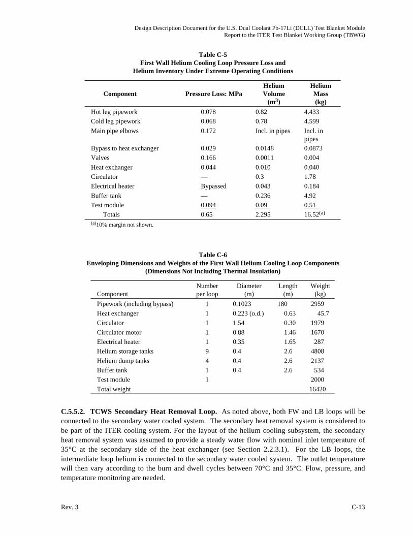
Design Description Document for the U.S. Dual Coolant Pb-17Li (DCLL) Test Blanket ModuleReport to the ITER Test Blanket Working Group (TBWG)
Rev. 3 C-13
Table C-5
First Wall Helium Cooling Loop Pressure Loss and
Helium Inventory Under Extreme Operating Conditions
Component Pressure Loss: MPa
Helium
Volume
(m3)
Helium
Mass
(kg)
Hot leg pipework 0.078 0.82 4.433
Cold leg pipework 0.068 0.78 4.599
Main pipe elbows 0.172 Incl. in pipes Incl. in
pipes
Bypass to heat exchanger 0.029 0.0148 0.0873
Valves 0.166 0.0011 0.004
Heat exchanger 0.044 0.010 0.040
Circulator — 0.3 1.78
Electrical heater Bypassed 0.043 0.184
Buffer tank — 0.236 4.92
Test module 0.094 0.09 0.51
Totals 0.65 2.295 16.52(a)
(a)10% margin not shown.
Table C-6
Enveloping Dimensions and Weights of the First Wall Helium Cooling Loop Components
(Dimensions Not Including Thermal Insulation)
Component
Number
per loop
Diameter
(m)
Length
(m)
Weight
(kg)
Pipework (including bypass) 1 0.1023 180 2959
Heat exchanger 1 0.223 (o.d.) 0.63 45.7
Circulator 1 1.54 0.30 1979
Circulator motor 1 0.88 1.46 1670
Electrical heater 1 0.35 1.65 287
Helium storage tanks 9 0.4 2.6 4808
Helium dump tanks 4 0.4 2.6 2137
Buffer tank 1 0.4 2.6 534
Test module 1 2000
Total weight 16420
C.5.5.2. TCWS Secondary Heat Removal Loop. As noted above, both FW and LB loops will be
connected to the secondary water cooled system. The secondary heat removal system is considered to
be part of the ITER cooling system. For the layout of the helium cooling subsystem, the secondary
heat removal system was assumed to provide a steady water flow with nominal inlet temperature of
35°C at the secondary side of the heat exchanger (see Section 2.2.3.1). For the LB loops, the
intermediate loop helium is connected to the secondary water cooled system. The outlet temperature
will then vary according to the burn and dwell cycles between 70°C and 35°C. Flow, pressure, and
temperature monitoring are needed.

Design Description Document for the U.S. Dual Coolant Pb-17Li (DCLL) Test Blanket ModuleReport to the ITER Test Blanket Working Group (TBWG)
C-14 Rev. 3
C.6. TRITIUM EXTRACTION
Specifications important for tritium recovery are summarized in Table C-7. The first tritium
generation rate in Table C-7 is the rate generated during a plasma pulse. When the plasma is off, of
course, no tritium is generated. The operational scenario considered was: plasma on for 450 s,
plasma off for 1800 s and overall 25% availability. This gives the time averaged tritium generation
rate shown.
Table C-7
Tritium Recovery Specifications
He LiBeF3 FLiNaBe
Tin/Tout (°C) 380/440 420/520 360/520
Coolant pressure (MPa/atm) 8/7.9 1/9.9 1/.9.9
Mass flow rate (kg/s) 1.514 4.86 2.98
Density (kg/m3) 5.33 2000 1900
@440°C @540°C @500°C
Tritium generation rate during pulse (gm/s) 2.09 10–6 2.09 10–6 2.09 10–6
Average tritium generation rate (gm/s) 1.05 10–7 1.05 10–7 1.05 10–7
MW (gm/mole) 72.95 57.94
Molar flowrate (mole/s) 66.62 51.43
Tritium molar flowrate (mole/s) 3.48 10–7 3.48 10–7
Loop volume (m3) 0.5 0.5
Heat exchanger area (m2)
Breeder to He 37
He to water 0.536 4.7
Heat exchanger tube thickness (mm) 0.5 0.5
Solubility (at. fr./Pa0.5)
References for Appendix C
[C-1] Y. Poitevin et al. “WSG2-LiPb-LAFS-He Blanket Line Preparation Document on Integral-
TBM & Related Requirements,” TBWG-12 Meeting, Naka, Japan, Mar 2004.