Embed Size (px)
Citation preview

Design Conventions
for Catalogues and Specifications

DisclaimerInformation of a technical nature, and particulars of the product and its use, is given by AVEVASolutions Ltd and its subsidiaries without warranty. AVEVA Solutions Ltd and its subsidiaries disclaimany and all warranties and conditions, expressed or implied, to the fullest extent permitted by law.
Neither the author nor AVEVA Solutions Ltd, or any of its subsidiaries, shall be liable to any person orentity for any actions, claims, loss or damage arising from the use or possession of any information,particulars, or errors in this publication, or any incorrect use of the product, whatsoever.
CopyrightCopyright and all other intellectual property rights in this manual and the associated software, and everypart of it (including source code, object code, any data contained in it, the manual and any otherdocumentation supplied with it) belongs to AVEVA Solutions Ltd or its subsidiaries.
All other rights are reserved to AVEVA Solutions Ltd and its subsidiaries. The information contained inthis document is commercially sensitive, and shall not be copied, reproduced, stored in a retrievalsystem, or transmitted without the prior written permission of AVEVA Solutions Ltd Where suchpermission is granted, it expressly requires that this Disclaimer and Copyright notice is prominentlydisplayed at the beginning of every copy that is made.
The manual and associated documentation may not be adapted, reproduced, or copied, in any materialor electronic form, without the prior written permission of AVEVA Solutions Ltd. The user may also notreverse engineer, decompile, copy, or adapt the associated software. Neither the whole, nor part of theproduct described in this publication may be incorporated into any third-party software, product,machine, or system without the prior written permission of AVEVA Solutions Ltd, save as permitted bylaw. Any such unauthorised action is strictly prohibited, and may give rise to civil liabilities and criminalprosecution.
The AVEVA products described in this guide are to be installed and operated strictly in accordance withthe terms and conditions of the respective licence agreements, and in accordance with the relevantUser Documentation. Unauthorised or unlicensed use of the product is strictly prohibited.
First published September 2007
© AVEVA Solutions Ltd, and its subsidiaries 2007
AVEVA Solutions Ltd, High Cross, Madingley Road, Cambridge, CB3 0HB, United Kingdom
TrademarksAVEVA and Tribon are registered trademarks of AVEVA Solutions Ltd or its subsidiaries. Unauthoriseduse of the AVEVA or Tribon trademarks is strictly forbidden.
AVEVA product names are trademarks or registered trademarks of AVEVA Solutions Ltd or itssubsidiaries, registered in the UK, Europe and other countries (worldwide).
The copyright, trade mark rights, or other intellectual property rights in any other product, its name orlogo belongs to its respective owner.
AVEVA Solutions Ltd
AVEVA
Design Conventions i
1 About This Guide11.1 Who Should Read This Guide11.2 Purpose of the Guide11.3 What the Guide Contains11.4 Other Sources of Information2
2 Conventions for Setting Up SteelworkCatalogues and Specifications12.1 Catalogues12.1.1 Standard Catalogue Reference Data12.1.2 Administrative Elements22.2 Datasets42.2.1 Standard Profile Catalogue42.2.2 Standard Fittings Catalogue52.2.3 Standard Structural Joints62.3 Specifications102.3.1 Specification for Structural Profiles112.3.2 Specification to Limit Panel Thickness112.3.3 Specification for Structural Fittings122.3.4 Specification for Structural Panel Fittings132.3.5 Specification for Structural Joints142.4 Materials in DESIGN15
3 Conventions for Setting Up Hangers & Supports Catalogues and Specs.13.1 Introduction13.1.1 The Hanger Catalogue13.2 Hanger Specifications43.3 Catalogue Naming Conventions for Catalogue /PSL-HANG-CAT4
4 Design Parameters & Selector Lists1

AVEVA
5 Hangers & Supports15.1 Naming Conventions for Hanger Configuration Specifications15.2 Hangers & Supports Configurations and Data Tables195.2.1 Configurations195.2.2 Hanger Configurations195.2.3 Hanger Configuration Specifications265.2.4 Support Configuration Specifications295.2.5 Data Tables29
Conventions for Catalogues and SpecificationsAbout This Guide
1 About This Guide
1.1 Who Should Read This GuideThis guide is intended for specialists who are responsible for building up and maintainingthe standard Catalogue databases within a project team.
1.2 Purpose of the GuideAlthough in principle you have a lot of flexibility in the ways in which you can construct thedatabase hierarchy for Catalogues and Specifications, in practice it is very important thatyou follow strict conventions within any given project to ensure complete compatibility of alldata within that project. Further, unless there are exceptional reasons for not doing so, it issensible to adopt common conventions for structuring all PDMS databases within yourcompany, thus simplifying the exchange of data between projects.
If you intend to use the standard applications for building Catalogue databases (usingPARAGON) and for accessing those databases during the Plant Design process (usingDESIGN), it is important that your data structures are compatible with those expected by theapplication macros. If this is not so, the transfer of information to and from the databasesmight not work successfully and the applications could fail.
This guide explains, with some examples, the essential features of the conventions used inbuilding up the Catalogues and Specifications which are supplied by AVEVA. You mustfollow these conventions in your own Catalogues and Specifications if you want thestandard AVEVA applications to work reliably with your data. In particular, some parts of theCatalogue database have been used to store information which is essential for thesuccessful use of some design applications but which is not obvious catalogue data by theconventional definitions; for example, the Hangers and Supports application uses datastored in user-defined attributes in the Catalogues and Specifications to access associatedinformation needed by the application.
1.3 What the Guide ContainsThis version of the guide includes the detailed data needed by two major types ofapplication supplied for use with DESIGN:
• Chapter 2 details the conventions used for setting up the structural Catalogues andSpecifications used by the Beams & Columns and Panels & Plates applications.
• Chapter 3 details the conventions used for setting up the structural Catalogues andSpecifications used by the Hangers & Supports applications.
• Chapter 4 details the Design Parameters and Selector lists.• Chapter 5 lists the full Specification Tables used to hold data specific to the Hangers &
Supports application.
12.0 1:1© 2007 AVEVA Solutions Ltd

Conventions for Catalogues and SpecificationsAbout This Guide
1.4 Other Sources of InformationThis guide does not attempt to tell you how to build Catalogue databases; it onlysummarises the final format for the data which you should seek to achieve. For details ofthe commands and specific applications which you need to use to carry out your work, referto the Catalogues and Specifications Reference Manual.
12.0 1:2© 2007 AVEVA Solutions Ltd
Conventions for Catalogues and SpecificationsConventions for Setting Up Steelwork Catalogues and
2 Conventions for Setting Up SteelworkCatalogues and Specifications
2.1 CataloguesYou must use the following conventions for structural catalogues so that the DESIGNapplications can recognise them and so that the PARAGON applications can use them:
• The PURPose of the CATAlogue must be set to one of the following: STL, FITT, JOINor PFIT. This ensures that any specifications and applications which are built canrecognise the correct catalogue element. Thus the steel Profile specification looks forthe purpose STL, the Joint specification looks for the purpose JOIN, the Fittingspecification looks for the purpose FITT and the Panel Fitting specification looks for thepurpose PFIT. A meaningful DESCription is also beneficial.
• The PURPose of the STSEction must be set to REF for Reference Data, PRFL forProfiles, FITT for Fittings, JOIN for Joints and PFIT for Panel Fittings.
• The PURPose of the STCAtegory must be set to REF for Reference Data, PRFL forProfiles, FITT for Fittings, JOIN for Joints and PFIT for Panel Fittings.
• The GTYPE of the Profile, Fitting, Joint or Panel Fitting must be set. This ensures thatspecific restrictions can be applied to Joints and Fittings when building thespecifications. For example: any Section with a GTYPE set to BEAM can be used witha Joint which has its GTYPE set to BEAM; any Fitting with a GTYPE set to FITT can beused with any Fitting specification.
• The purpose of a CSTANdard is to let you define in a text string the type of standardthat is being used. It is used purely for information and administration of the Catalogue.For example, the CSTANdard for British Sections is BS 5950.
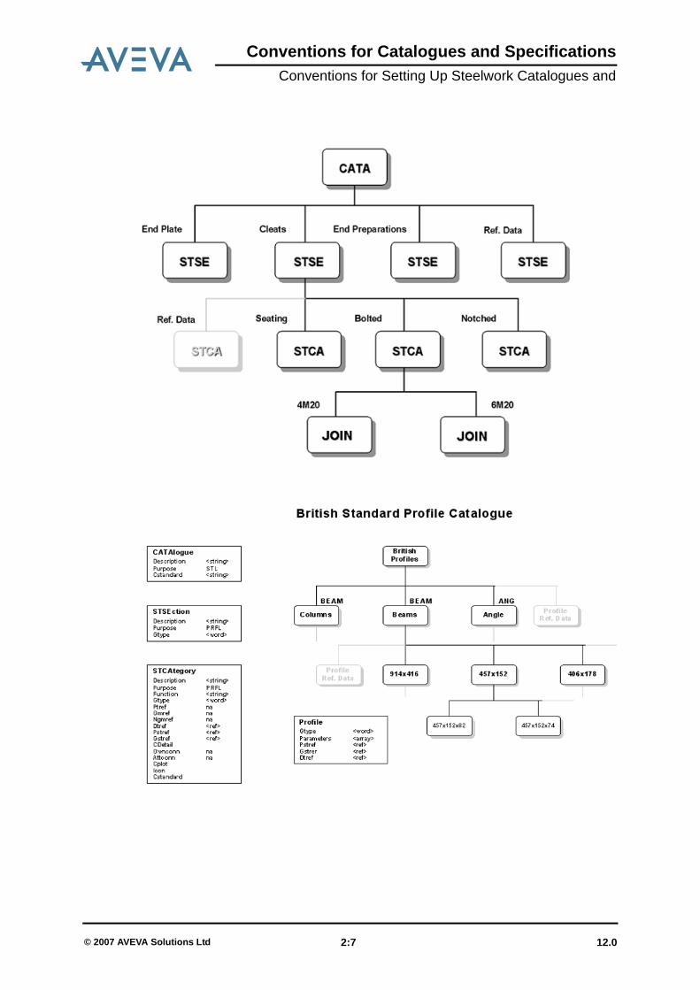
The diagrams in the following subsection illustrate the structure of the catalogues.
2.1.1 Standard Catalogue Reference DataAs with the piping catalogue, there are many ways in which you can structure yoursteelwork catalogues. The same two ways of structuring both types of catalogue arepreferred, the difference being the types of administrative elements used. However,whereas for piping there is only one type of catalogue (namely for piping components), thefollowing three types of catalogue are used for steelwork:
• PROFILES• JOINTS• FITTINGS (FITT and PFIT)
The basic layout of the catalogues is the same as for piping, i.e. where the reference data isstored, but the way in which the data is separated differs.
12.0 2:1© 2007 AVEVA Solutions Ltd

Conventions for Catalogues and SpecificationsConventions for Setting Up Steelwork Catalogues and
2.1.2 Administrative Elements
• CATAlogue
• STSEction - Structural Section
• STCAtegory - Structural Category
Description Description of catalogue
Purpose Purpose should be the same as the SPEC with which thecatalogue is to be used (STL, FITT, JOIN, PFIT etc.)
Cstandard Catalogue standard
Description Description of Section
Gtype- Generic type of element contained in section; this should bethe same as the type of element used in DESIGN,e.g.BEAM
Description Description of category
Purpose Purpose should equate to the STYP of the items asdefined in the Spec
Function Description
Gtype Identifies the Generic element type
12.0 2:2© 2007 AVEVA Solutions Ltd
Conventions for Catalogues and SpecificationsConventions for Setting Up Steelwork Catalogues and
• PTSE - Point Sets
• GMSE - 3D Geometry Set
Skey not applicable
Ptref Point set reference
Gmref Geometry set reference
Ngmref Negative geometry reference
DataSetRef Data set reference
Pstreference Pline set reference
Gstreference Profile set reference
CDetail Detail reference
Ownconn Owning connection profile type
Attconn Attached connection profile type
CPlot Plot file for reference used in documentation
Icon Icon name
Cstandard Standard·
Description Description of category
Description Description of point set
Gtype Identifies the Generic element type
Skey Symbol Key to which point set relates
Purpose Purpose of point set
Description Description of geometry set
Gtype Identifies the Generic element type
Purpose Purpose of geometry set
12.0 2:3© 2007 AVEVA Solutions Ltd
Conventions for Catalogues and SpecificationsConventions for Setting Up Steelwork Catalogues and
• NGMS - Negative Geometry Sets
• DTSE - Datasets
• PTSS - Point sets
• GMSS - 2D Geometry Set
2.2 DatasetsThe general purpose of Datasets is twofold :
• To let you query catalogue parameters• To let you input design parameters via simple forms and menus
(See Catalogues and Specifications Reference Manual Section 3)
2.2.1 Standard Profile CatalogueThe Profile catalogue should be structured so that the separation of the data is sensible, e.g.all sections of the same generic profile should be under the structural section. Thesegregation beneath the section should be used to associate groups within the generic type;for example, in the case of British Standards, each category should contain sections with the
Description Description of geometry set
Gtype Identifies the Generic element type
Purpose Purpose of geometry set
Description Description of dataset
Gtype Identifies the Generic element type
Purpose Purpose of dataset
Description Description of point set
Gtype Identifies the Generic element type
Purpose Purpose of point set
Description Description of geometry structural set
Gtype Identifies the Generic element type
Purpose Purpose of geometry structural set
12.0 2:4© 2007 AVEVA Solutions Ltd
Conventions for Catalogues and SpecificationsConventions for Setting Up Steelwork Catalogues and
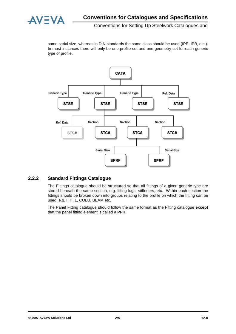
same serial size, whereas in DIN standards the same class should be used (IPE, IPB, etc.).In most instances there will only be one profile set and one geometry set for each generictype of profile.
2.2.2 Standard Fittings CatalogueThe Fittings catalogue should be structured so that all fittings of a given generic type arestored beneath the same section, e.g. lifting lugs, stiffeners, etc. Within each section thefittings should be broken down into groups relating to the profile on which the fitting can beused, e.g. I, H, L, COLU, BEAM etc.
The Panel Fitting catalogue should follow the same format as the Fitting catalogue exceptthat the panel fitting element is called a PFIT.
12.0 2:5© 2007 AVEVA Solutions Ltd
Conventions for Catalogues and SpecificationsConventions for Setting Up Steelwork Catalogues and
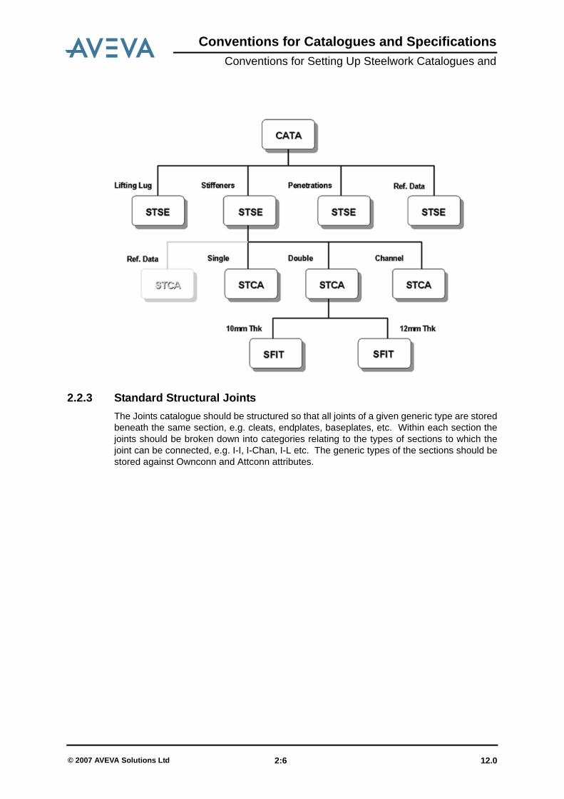
2.2.3 Standard Structural JointsThe Joints catalogue should be structured so that all joints of a given generic type are storedbeneath the same section, e.g. cleats, endplates, baseplates, etc. Within each section thejoints should be broken down into categories relating to the types of sections to which thejoint can be connected, e.g. I-I, I-Chan, I-L etc. The generic types of the sections should bestored against Ownconn and Attconn attributes.
12.0 2:6© 2007 AVEVA Solutions Ltd
Conventions for Catalogues and SpecificationsConventions for Setting Up Steelwork Catalogues and
12.0 2:7© 2007 AVEVA Solutions Ltd

Conventions for Catalogues and SpecificationsConventions for Setting Up Steelwork Catalogues and
12.0 2:8© 2007 AVEVA Solutions Ltd

Conventions for Catalogues and SpecificationsConventions for Setting Up Steelwork Catalogues and
12.0 2:9© 2007 AVEVA Solutions Ltd

Conventions for Catalogues and SpecificationsConventions for Setting Up Steelwork Catalogues and
2.3 SpecificationsThe following conventions for structural specifications must be followed to ensure that acorrect specification is built. The application follows strict rules when building thesespecifications and reads the specification in a tabulated format. Description should be givenat the correct level and any question of Tanswers must be input for the forms and menus tobe correctly built. The steelwork specifications work in a different way to pipingspecifications, where there can be more than one answer. For example, a typicalconnection for two beams can either be a bolted or welded connection; hence there can betwo answers to one question.
12.0 2:10© 2007 AVEVA Solutions Ltd
Conventions for Catalogues and SpecificationsConventions for Setting Up Steelwork Catalogues and
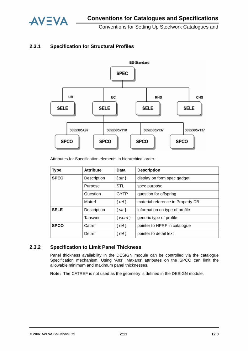
2.3.1 Specification for Structural Profiles
Attributes for Specification elements in hierarchical order :
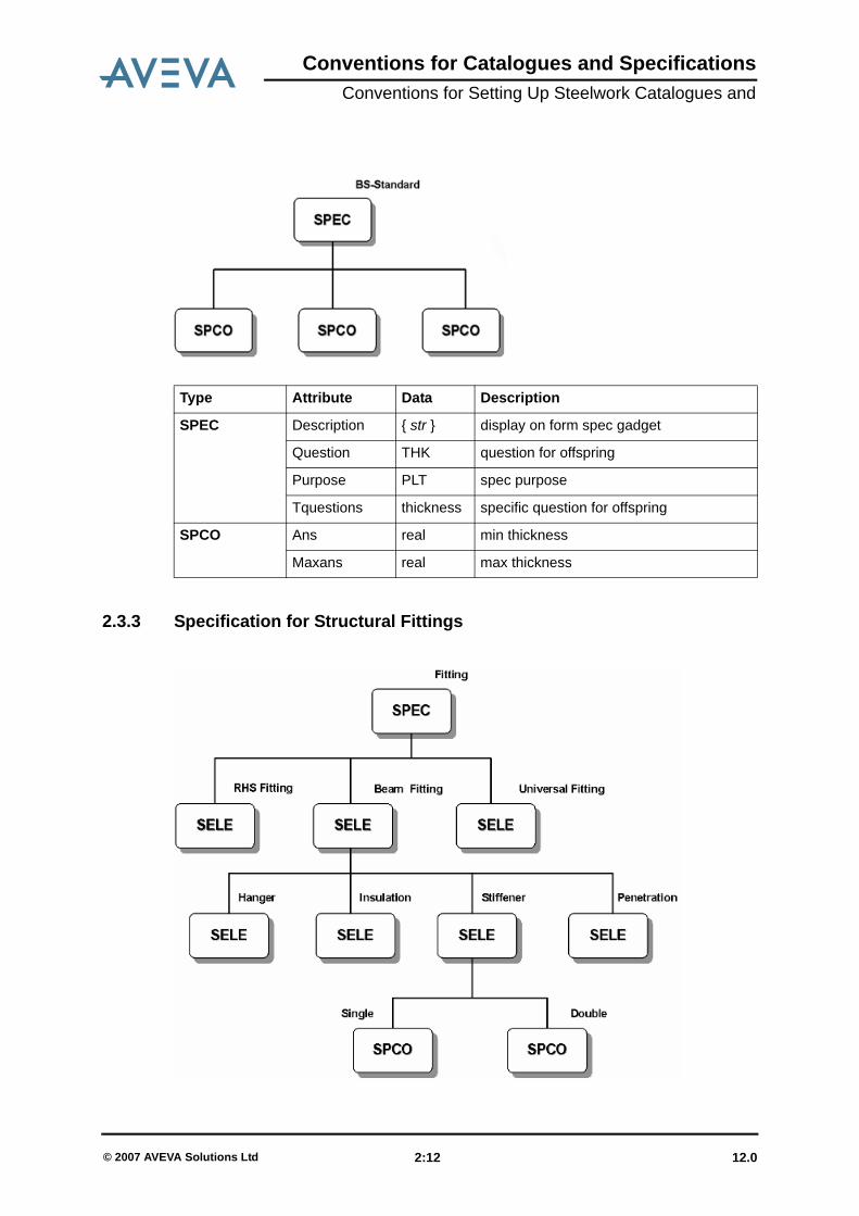
2.3.2 Specification to Limit Panel ThicknessPanel thickness availability in the DESIGN module can be controlled via the catalogueSpecification mechanism. Using ‘Ans’ ‘Maxans’ attributes on the SPCO can limit theallowable minimum and maximum panel thicknesses.
Note: The CATREF is not used as the geometry is defined in the DESIGN module.
Type Attribute Data Description
SPEC Description { str } display on form spec gadget
Purpose STL spec purpose
Question GYTP question for offspring
Matref { ref } material reference in Property DB
SELE Description { str } information on type of profile
Tanswer { word } generic type of profile
SPCO Catref { ref } pointer to HPRF in catalogue
Detref { ref } pointer to detail text
12.0 2:11© 2007 AVEVA Solutions Ltd
Conventions for Catalogues and SpecificationsConventions for Setting Up Steelwork Catalogues and
2.3.3 Specification for Structural Fittings
Type Attribute Data Description
SPEC Description { str } display on form spec gadget
Question THK question for offspring
Purpose PLT spec purpose
Tquestions thickness specific question for offspring
SPCO Ans real min thickness
Maxans real max thickness
12.0 2:12© 2007 AVEVA Solutions Ltd

Conventions for Catalogues and SpecificationsConventions for Setting Up Steelwork Catalogues and
Attributes for Specification elements in hierarchical order :
2.3.4 Specification for Structural Panel Fittings
Type Attribute Data Description
SPEC Description { str } display on form spec gadget
Purpose FITT spec purpose
Question TYPE question for offspring
Matref { ref } material reference in Property DB
SELE Description { str } information on type of profile
Tanswer { word } generic type of profile that can own thefitting. ANY will allow a fitting to be usedon any profile type.
Questions STYP question for offspring
SELE Description { str } display on form stype gadget
Tanswer { word } sub-type of fitting, e.g. LUG, HOLE, etc.
SPCO Catref { ref } pointer to HFIT in catalogue
Detref { ref } pointer to detail text
12.0 2:13© 2007 AVEVA Solutions Ltd
Conventions for Catalogues and SpecificationsConventions for Setting Up Steelwork Catalogues and
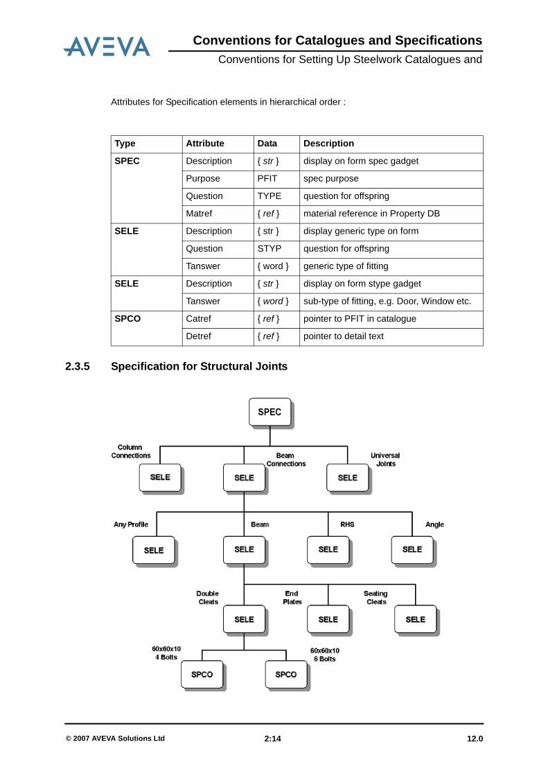
Attributes for Specification elements in hierarchical order :
2.3.5 Specification for Structural Joints
Type Attribute Data Description
SPEC Description { str } display on form spec gadget
Purpose PFIT spec purpose
Question TYPE question for offspring
Matref { ref } material reference in Property DB
SELE Description { str } display generic type on form
Question STYP question for offspring
Tanswer { word } generic type of fitting
SELE Description { str } display on form stype gadget
Tanswer { word } sub-type of fitting, e.g. Door, Window etc.
SPCO Catref { ref } pointer to PFIT in catalogue
Detref { ref } pointer to detail text
12.0 2:14© 2007 AVEVA Solutions Ltd

Conventions for Catalogues and SpecificationsConventions for Setting Up Steelwork Catalogues and
Attributes for Specification elements in hierarchical order
2.4 Materials in DESIGNFor the materials of a structural element (MATR) to be set in DESIGN, you must be able tosee a Properties DB containing the available materials.
To create a Material World, carry out the following steps:
1. In ADMIN, change the module definition for PARAGON so that it has Read/Writeaccess to the Properties DB, thus:
edit module PARAGON mode PROP rw
2. Create a Properties DB (if there is not one already) and include it into the relevantdatabases. If there is a Properties DB with a Material World already existing, go to step4.
3. Enter PROPCON in Read/Write mode and create a MATW.4. Enter PARAGON in Read/Write mode (R/W to the Properties DB) and run the property
loading macro, thus:
$m/%PDMSUI%/DES/DATA/MLOADPROP
By default, the DENSITY.DAT data in the PDMSDFLTS directory will be loaded into thefirst Material World found. Where elements already exist, the macro will modify them tothe values contained in the file.
Type Attribute Data Description
SPEC Description { str } display on form spec gadget
Purpose JOIN spec purpose
Question OTYP question for offspring
Matref { ref } material reference in Property DB
SELE Description { str } display on form stype gadget
Tanswer { word } generic type of profile which joints can beowned by. ANY will allow joints to beowned by any profile, NONE will allowsetting of PJOI specrefs.
Question ATYP question for offspring
SELE Description { str } information on type of profile
Tanswer { word } generic type of profile that can be attachedto joint. ANY will allow any type of profile tobe attached to the joint.
Question STYP question for offspring
SPCO Catref { ref } pointer to PFIT in catalogue
Detref { ref } pointer to detail text
12.0 2:15© 2007 AVEVA Solutions Ltd
Conventions for Catalogues and SpecificationsConventions for Setting Up Steelwork Catalogues and
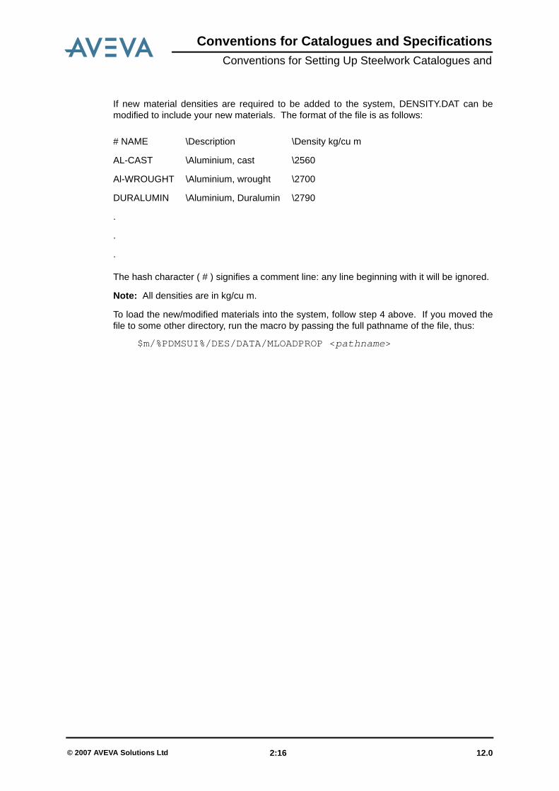
If new material densities are required to be added to the system, DENSITY.DAT can bemodified to include your new materials. The format of the file is as follows:
The hash character ( # ) signifies a comment line: any line beginning with it will be ignored.
Note: All densities are in kg/cu m.
To load the new/modified materials into the system, follow step 4 above. If you moved thefile to some other directory, run the macro by passing the full pathname of the file, thus:
$m/%PDMSUI%/DES/DATA/MLOADPROP <pathname>
# NAME \Description \Density kg/cu m
AL-CAST \Aluminium, cast \2560
Al-WROUGHT \Aluminium, wrought \2700
DURALUMIN \Aluminium, Duralumin \2790
.
.
.
12.0 2:16© 2007 AVEVA Solutions Ltd

Conventions for Catalogues and SpecificationsConventions for Setting Up Hangers & Supports Catalogues and
3 Conventions for Setting Up Hangers & Supports Catalogues and Specs.
3.1 Introduction
3.1.1 The Hanger CatalogueThe Hanger catalogue is analogous to the Piping catalogue. Components are created inmuch the same way, using the element types PCLA (Pipe Clamp), HELE (Hanger Element),ROD, and SCLA (Steel Clamp). You are advised to study the sample catalogue provided byAVEVA, together with these notes, before creating your own catalogue components.
Component Point Sets
In general, arrive and leave p-points should be in the same direction as the axes aboutwhich the component can be rotated at the respective ends. For variable heightcomponents, the positions of arrive and leave p-points should be related to the distancebetween the leave of the previous and the arrive of the next, and not the actual height. If amaximum or minimum distance is applicable to the component, p-points should be providedfrom which this distance can be measured.
Bores
For hangers, the PBOR attribute is interpreted as the equivalent hanger rod diameter. It isvalid to have a zero-bore rod and still successfully use the CHOOSE command. Itemswhich are not sized by rod (or pin) diameter or which do not have a concept of rod diameter(such as pipe shoes and welded attachments) should have PBOR set to zero. In suchcases, the system will not attempt to set the LSRO attribute of the component.
Pipe Clamps (PCLAs)
Pipe clamps should always have their P1 pointing in the direction of flow in the pipe as thisis the direction used for the hanger head. For PCLAs to be used on implied tube, the P2 willbe perpendicular to the P1. For PCLAs to be used on piping components (e.g. ELBOs) theP2 will be opposite in direction to the P1. The PBOR of the pipe end of the PCLA (P1)should be set to the equivalent nominal bore of the pipe. Some PCLAs (such as U-Bolts)can be applied to sloping pipes and the angle between the P1 and P2 will be variable. Insuch cases, put the DDANG on the P2.
Steel Clamps (SCLAs)
A p-point should be provided which will be used to orientate the SCLA with respect to thesteelwork to which it is attached. The direction should be that of the attached steel whenconnected to the flange.
12.0 3:1© 2007 AVEVA Solutions Ltd

Conventions for Catalogues and SpecificationsConventions for Setting Up Hangers & Supports Catalogues and
• Material TextsThe supplied catalogue uses the XTEX attribute of HMTE elements to store material data
• Detail TextsThe supplied catalogue uses the RTEX attribute of HDTE elements to store longdescriptions of components for drawings, etc.; the STEX attribute to store concise orderingcodes for MTO, etc.; and the TTEX attribute to store details of additional items which formpart of the component but which need to be ordered separately.
• DatasetsThe Hangers & Supports application makes great use of the catalogue Datasets. Thefollowing rules apply to their use.
For Datakeys which tell the appware to set certain Design Parameters:• The PPROP attribute must be set to an expression which gives the value of the design
parameter; for example, (ATTRIB DESPARA[1]).• The PURP attribute must be set to DESP.• The NUMB attribute must be set to the number of the relevant design parameter.
P-Point Connection Types:
NONE No connection
WELD Welded connection
FPIN Female pin
MPIN Male pin
BOLT Bolted connection
RHOL Right-hand-threaded hole
RROD Right-hand-threaded rod
LHOL Left-hand-threaded hole
LROD Left-hand-threaded rod
CLAM Clamped connection
HOLE Hole (for rod)
FSWA Female spherical washer
MSWA Male spherical washer
12.0 3:2© 2007 AVEVA Solutions Ltd
Conventions for Catalogues and SpecificationsConventions for Setting Up Hangers & Supports Catalogues and
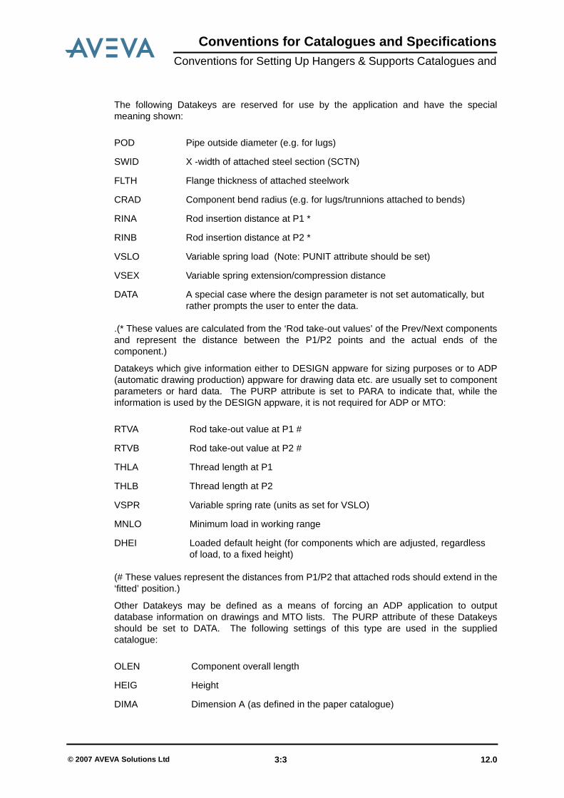
The following Datakeys are reserved for use by the application and have the specialmeaning shown:
.(* These values are calculated from the ‘Rod take-out values’ of the Prev/Next componentsand represent the distance between the P1/P2 points and the actual ends of thecomponent.)
Datakeys which give information either to DESIGN appware for sizing purposes or to ADP(automatic drawing production) appware for drawing data etc. are usually set to componentparameters or hard data. The PURP attribute is set to PARA to indicate that, while theinformation is used by the DESIGN appware, it is not required for ADP or MTO:
(# These values represent the distances from P1/P2 that attached rods should extend in the‘fitted’ position.)
Other Datakeys may be defined as a means of forcing an ADP application to outputdatabase information on drawings and MTO lists. The PURP attribute of these Datakeysshould be set to DATA. The following settings of this type are used in the suppliedcatalogue:
POD Pipe outside diameter (e.g. for lugs)
SWID X -width of attached steel section (SCTN)
FLTH Flange thickness of attached steelwork
CRAD Component bend radius (e.g. for lugs/trunnions attached to bends)
RINA Rod insertion distance at P1 *
RINB Rod insertion distance at P2 *
VSLO Variable spring load (Note: PUNIT attribute should be set)
VSEX Variable spring extension/compression distance
DATA A special case where the design parameter is not set automatically, butrather prompts the user to enter the data.
RTVA Rod take-out value at P1 #
RTVB Rod take-out value at P2 #
THLA Thread length at P1
THLB Thread length at P2
VSPR Variable spring rate (units as set for VSLO)
MNLO Minimum load in working range
DHEI Loaded default height (for components which are adjusted, regardlessof load, to a fixed height)
OLEN Component overall length
HEIG Height
DIMA Dimension A (as defined in the paper catalogue)
12.0 3:3© 2007 AVEVA Solutions Ltd
Conventions for Catalogues and SpecificationsConventions for Setting Up Hangers & Supports Catalogues and
• Naming ConventionsA naming convention for catalogue components has been developed following theconventions of the ISOCAT style in use by AVEVA and a number of customers for manyyears. This convention is detailed later in this section.
3.2 Hanger SpecificationsIn order for the CHOOSE command to function correctly, the first question in the hangerspecification must be PBOR0.
The sample specification supplied uses the more descriptive TANS instead of the usualANS, and this is recommended to make the configuration macro code more readable.
Because, by default, the system uses the CHOOSE command, it is safe to assume thatsome questions will be left unanswered at design time. The specification should beconstructed taking this into consideration. For ease of use, the selectors STYP, TTYP andUTYP have been used, in that order, where multiple levels of selector are required.
It is important to set the DESC, PURP and :VISI attributes of the hanger specification.PURP and :VISI should be set to HANG and True, respectively.
Any Hangers & Supports specifications should reside in a SPWL with its PURP attribute setto HSUP.
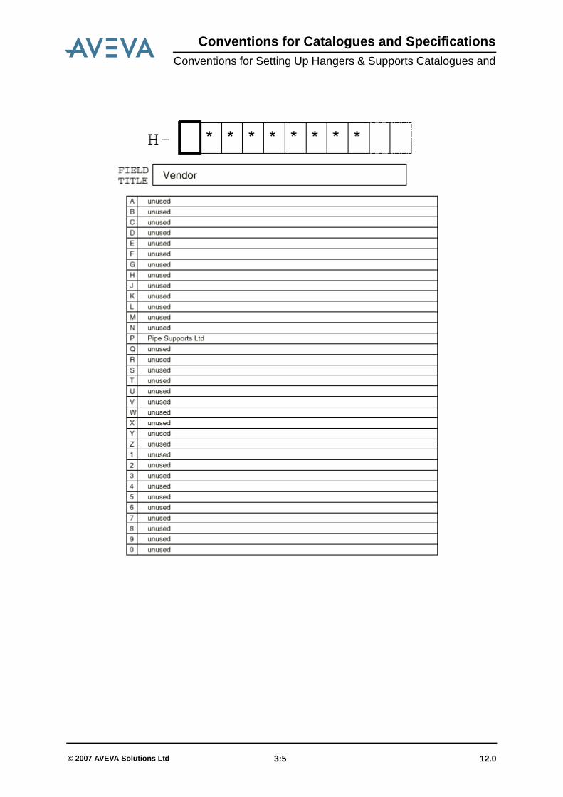
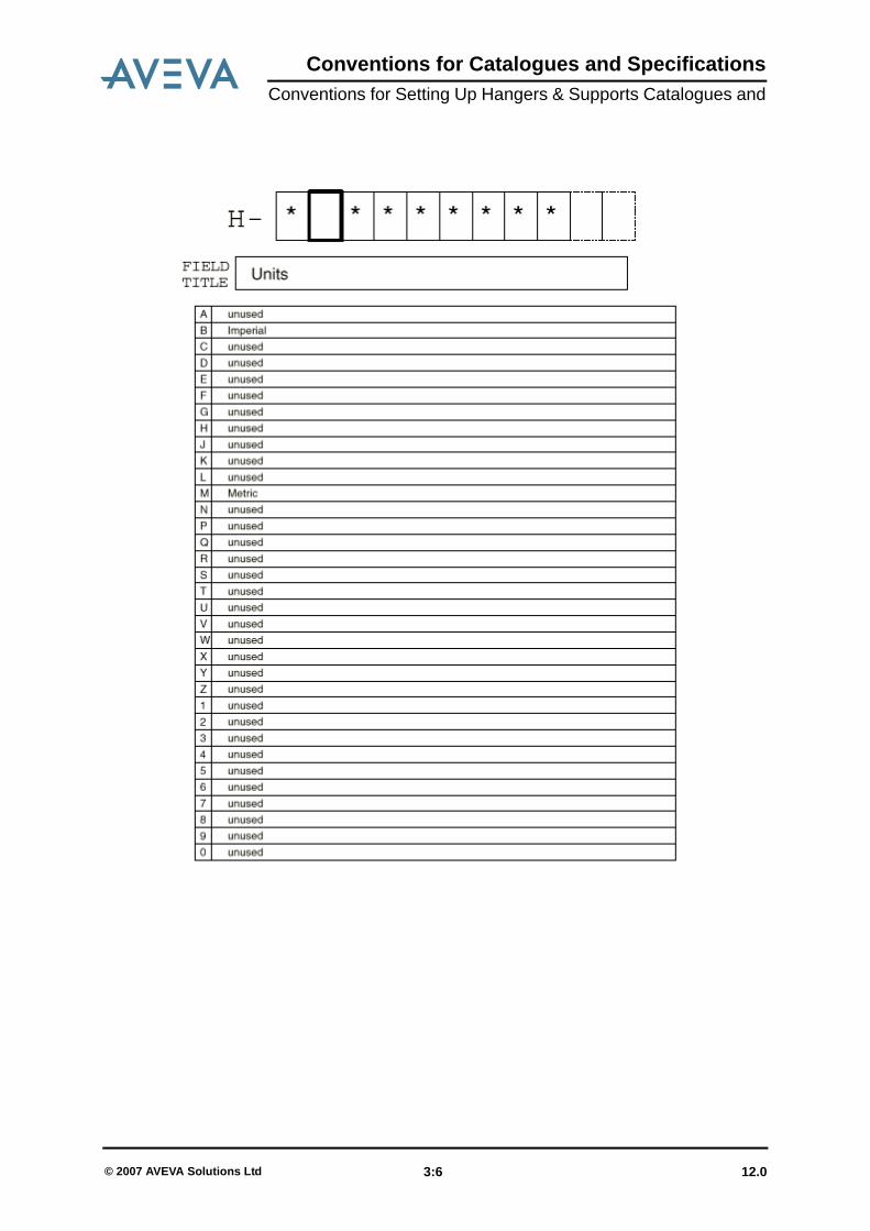
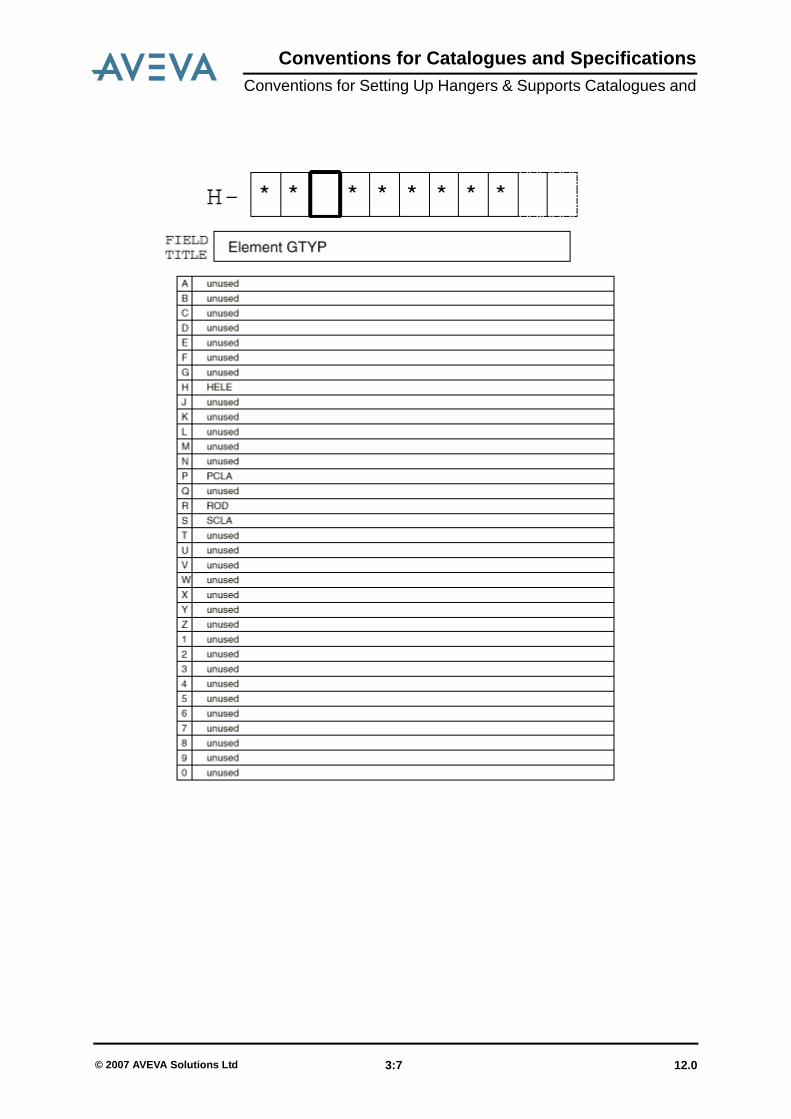
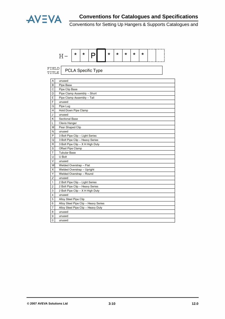
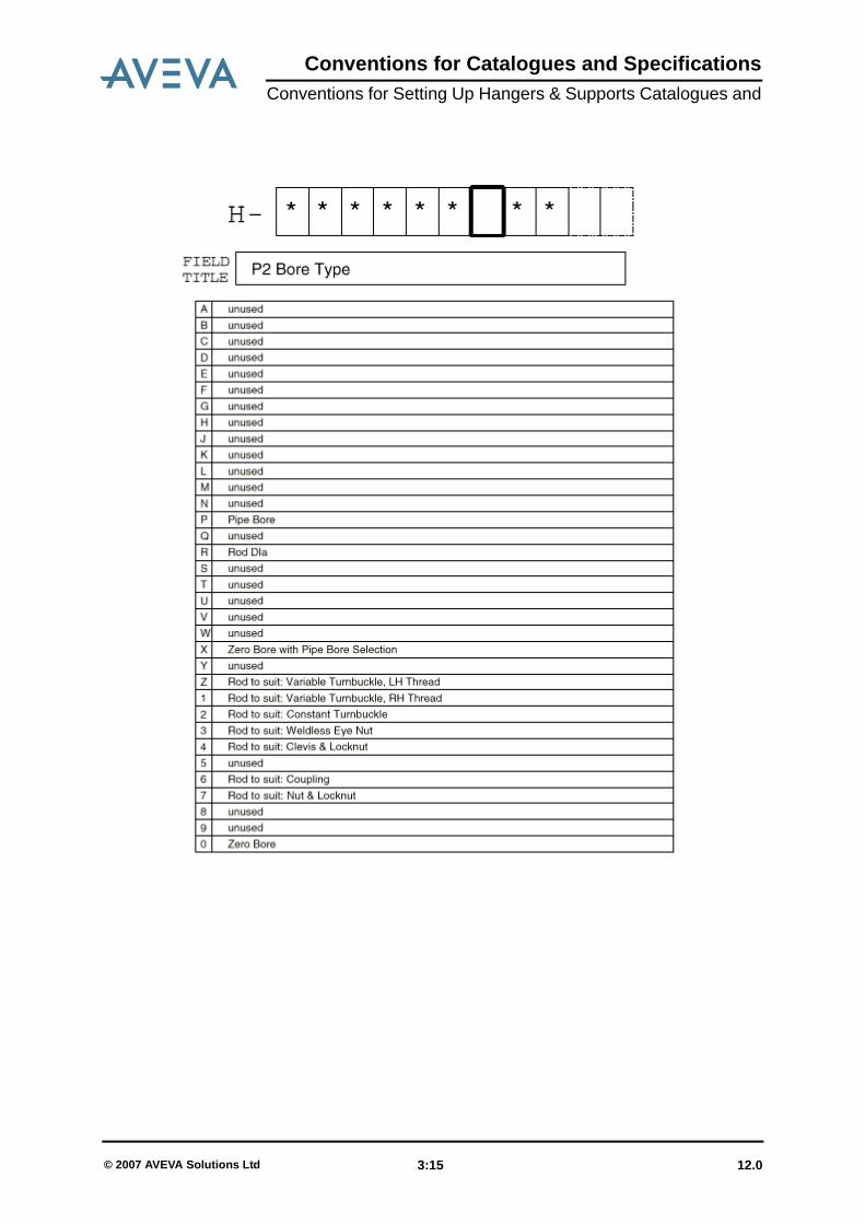
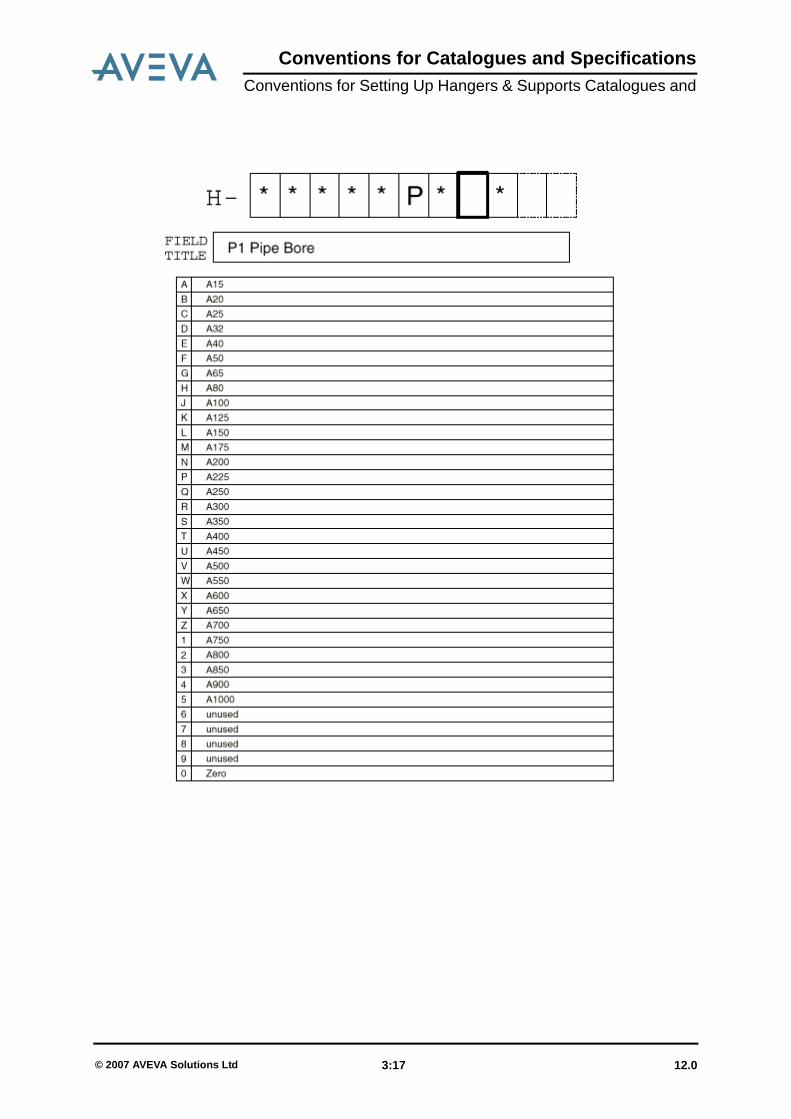
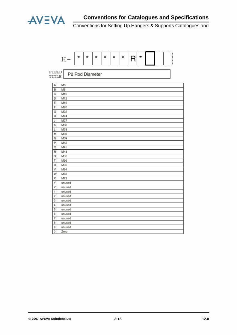
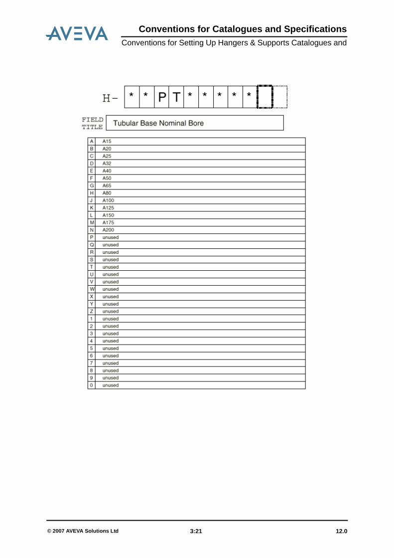
3.3 Catalogue Naming Conventions for Catalogue /PSL-HANG-CAT(Derived from the hanger catalogue of Pipe Supports Ltd)
12.0 3:4© 2007 AVEVA Solutions Ltd
Conventions for Catalogues and SpecificationsConventions for Setting Up Hangers & Supports Catalogues and
12.0 3:5© 2007 AVEVA Solutions Ltd
Conventions for Catalogues and SpecificationsConventions for Setting Up Hangers & Supports Catalogues and
12.0 3:6© 2007 AVEVA Solutions Ltd
Conventions for Catalogues and SpecificationsConventions for Setting Up Hangers & Supports Catalogues and
12.0 3:7© 2007 AVEVA Solutions Ltd

Conventions for Catalogues and SpecificationsConventions for Setting Up Hangers & Supports Catalogues and
12.0 3:8© 2007 AVEVA Solutions Ltd

Conventions for Catalogues and SpecificationsConventions for Setting Up Hangers & Supports Catalogues and
12.0 3:9© 2007 AVEVA Solutions Ltd
Conventions for Catalogues and SpecificationsConventions for Setting Up Hangers & Supports Catalogues and
12.0 3:10© 2007 AVEVA Solutions Ltd

Conventions for Catalogues and SpecificationsConventions for Setting Up Hangers & Supports Catalogues and
12.0 3:11© 2007 AVEVA Solutions Ltd

Conventions for Catalogues and SpecificationsConventions for Setting Up Hangers & Supports Catalogues and
12.0 3:12© 2007 AVEVA Solutions Ltd

Conventions for Catalogues and SpecificationsConventions for Setting Up Hangers & Supports Catalogues and
12.0 3:13© 2007 AVEVA Solutions Ltd

Conventions for Catalogues and SpecificationsConventions for Setting Up Hangers & Supports Catalogues and
12.0 3:14© 2007 AVEVA Solutions Ltd
Conventions for Catalogues and SpecificationsConventions for Setting Up Hangers & Supports Catalogues and
12.0 3:15© 2007 AVEVA Solutions Ltd

Conventions for Catalogues and SpecificationsConventions for Setting Up Hangers & Supports Catalogues and
12.0 3:16© 2007 AVEVA Solutions Ltd
Conventions for Catalogues and SpecificationsConventions for Setting Up Hangers & Supports Catalogues and
12.0 3:17© 2007 AVEVA Solutions Ltd
Conventions for Catalogues and SpecificationsConventions for Setting Up Hangers & Supports Catalogues and
12.0 3:18© 2007 AVEVA Solutions Ltd

Conventions for Catalogues and SpecificationsConventions for Setting Up Hangers & Supports Catalogues and
12.0 3:19© 2007 AVEVA Solutions Ltd

Conventions for Catalogues and SpecificationsConventions for Setting Up Hangers & Supports Catalogues and
12.0 3:20© 2007 AVEVA Solutions Ltd
Conventions for Catalogues and SpecificationsConventions for Setting Up Hangers & Supports Catalogues and
12.0 3:21© 2007 AVEVA Solutions Ltd

Conventions for Catalogues and SpecificationsConventions for Setting Up Hangers & Supports Catalogues and
12.0 3:22© 2007 AVEVA Solutions Ltd
Conventions for Catalogues and SpecificationsDesign Parameters & Selector Lists
4 Design Parameters & Selector Lists
These lists are available in a separate PDF file and can be found here:
Design_Param_Sel_Lists.pdf.
Design Parameters & Selector Lists include two sections:• Design Parameters and Dataset Properties for PDMS Catalogue /PSL-HANG-CAT• Selector List for PDMS Specification /PSL
12.0 4:1© 2007 AVEVA Solutions Ltd

Conventions for Catalogues and SpecificationsDesign Parameters & Selector Lists
12.0 4:2© 2007 AVEVA Solutions Ltd

Conventions for Catalogues and SpecificationsHangers & Supports
5 Hangers & Supports
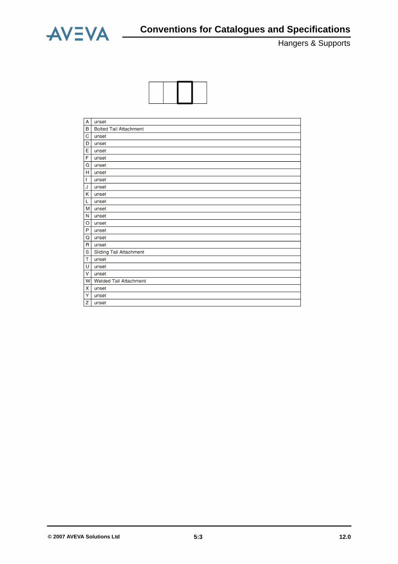
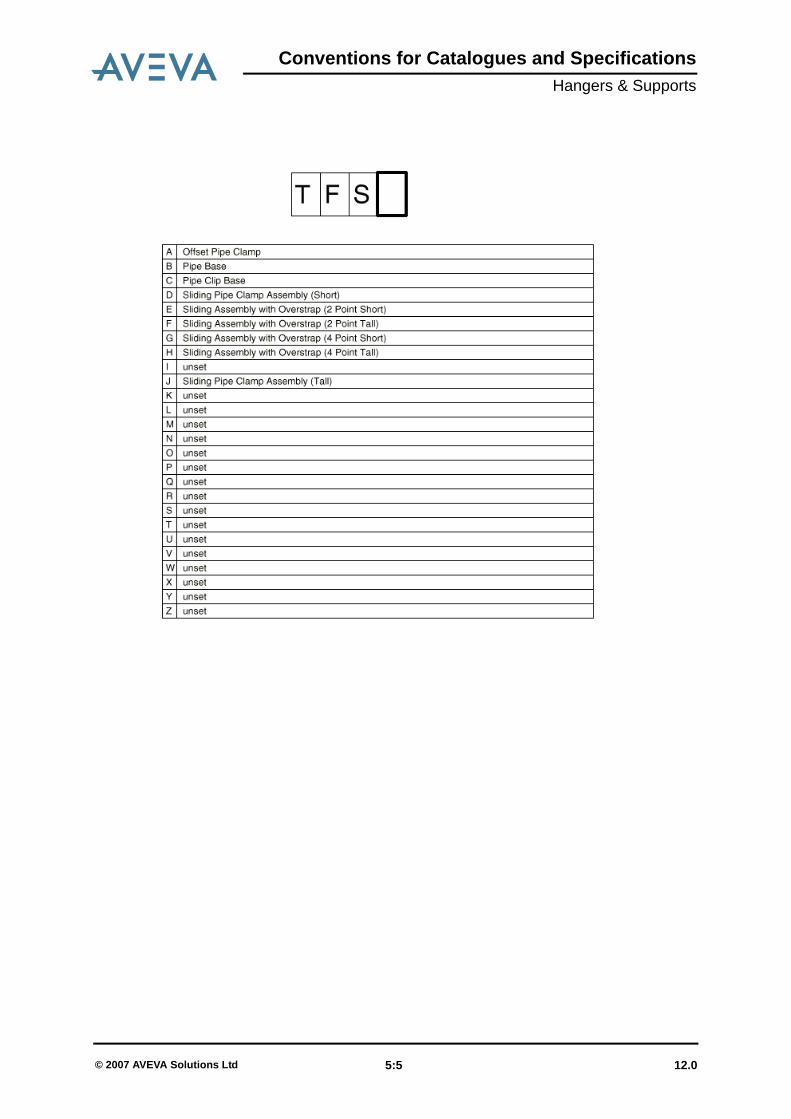
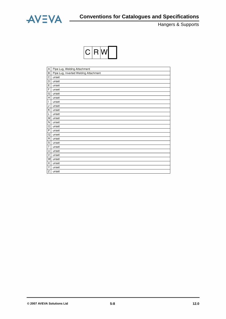
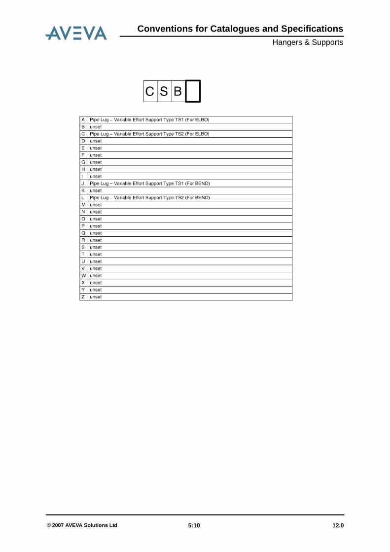
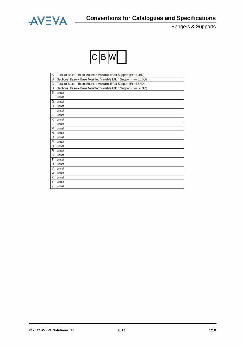
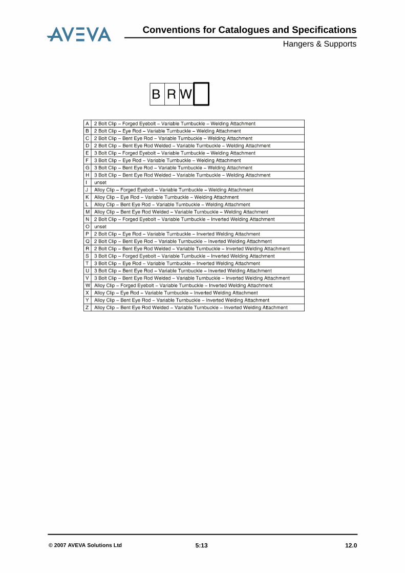
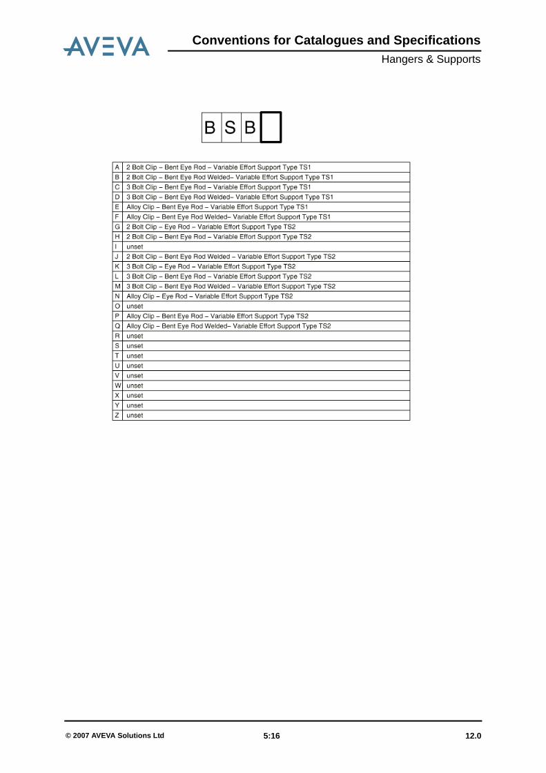
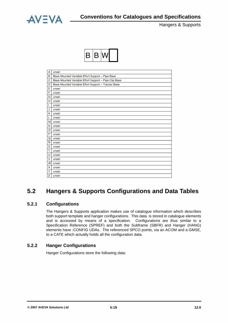
5.1 Naming Conventions for Hanger Configuration Specifications
12.0 5:1© 2007 AVEVA Solutions Ltd

Conventions for Catalogues and SpecificationsHangers & Supports
12.0 5:2© 2007 AVEVA Solutions Ltd
Conventions for Catalogues and SpecificationsHangers & Supports
12.0 5:3© 2007 AVEVA Solutions Ltd

Conventions for Catalogues and SpecificationsHangers & Supports
12.0 5:4© 2007 AVEVA Solutions Ltd
Conventions for Catalogues and SpecificationsHangers & Supports
12.0 5:5© 2007 AVEVA Solutions Ltd

Conventions for Catalogues and SpecificationsHangers & Supports
12.0 5:6© 2007 AVEVA Solutions Ltd

Conventions for Catalogues and SpecificationsHangers & Supports
12.0 5:7© 2007 AVEVA Solutions Ltd
Conventions for Catalogues and SpecificationsHangers & Supports
12.0 5:8© 2007 AVEVA Solutions Ltd

Conventions for Catalogues and SpecificationsHangers & Supports
12.0 5:9© 2007 AVEVA Solutions Ltd
Conventions for Catalogues and SpecificationsHangers & Supports
12.0 5:10© 2007 AVEVA Solutions Ltd
Conventions for Catalogues and SpecificationsHangers & Supports
12.0 5:11© 2007 AVEVA Solutions Ltd

Conventions for Catalogues and SpecificationsHangers & Supports
12.0 5:12© 2007 AVEVA Solutions Ltd
Conventions for Catalogues and SpecificationsHangers & Supports
12.0 5:13© 2007 AVEVA Solutions Ltd

Conventions for Catalogues and SpecificationsHangers & Supports
12.0 5:14© 2007 AVEVA Solutions Ltd

Conventions for Catalogues and SpecificationsHangers & Supports
12.0 5:15© 2007 AVEVA Solutions Ltd
Conventions for Catalogues and SpecificationsHangers & Supports
12.0 5:16© 2007 AVEVA Solutions Ltd

Conventions for Catalogues and SpecificationsHangers & Supports
12.0 5:17© 2007 AVEVA Solutions Ltd

Conventions for Catalogues and SpecificationsHangers & Supports
12.0 5:18© 2007 AVEVA Solutions Ltd
Conventions for Catalogues and SpecificationsHangers & Supports
5.2 Hangers & Supports Configurations and Data Tables
5.2.1 ConfigurationsThe Hangers & Supports application makes use of catalogue information which describesboth support template and hanger configurations. This data is stored in catalogue elementsand is accessed by means of a specification. Configurations are thus similar to aSpecification Reference (SPREF) and both the Subframe (SBFR) and Hanger (HANG)elements have :CONFIG UDAs. The referenced SPCO points, via an ACOM and a GMSE,to a CATE which actually holds all the configuration data.
5.2.2 Hanger ConfigurationsHanger Configurations store the following data:
12.0 5:19© 2007 AVEVA Solutions Ltd
Conventions for Catalogues and SpecificationsHangers & Supports
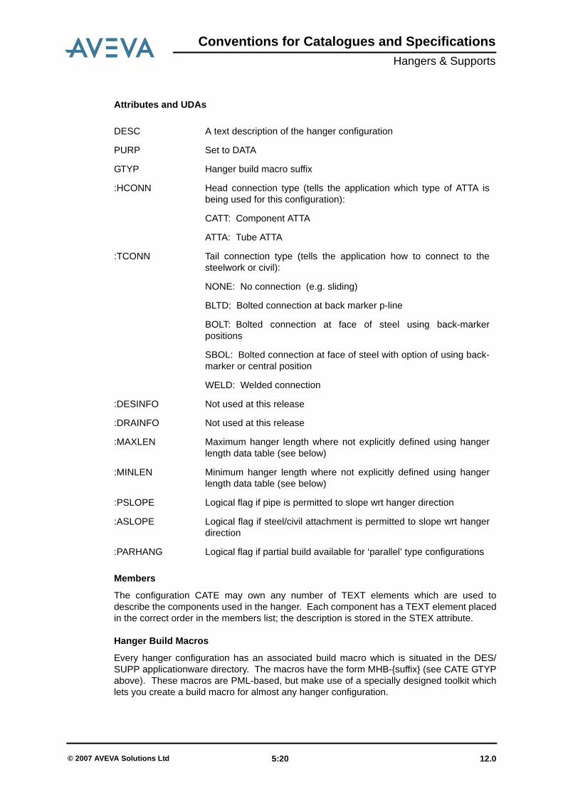
Attributes and UDAs
Members
The configuration CATE may own any number of TEXT elements which are used todescribe the components used in the hanger. Each component has a TEXT element placedin the correct order in the members list; the description is stored in the STEX attribute.
Hanger Build Macros
Every hanger configuration has an associated build macro which is situated in the DES/SUPP applicationware directory. The macros have the form MHB-{suffix} (see CATE GTYPabove). These macros are PML-based, but make use of a specially designed toolkit whichlets you create a build macro for almost any hanger configuration.
DESC A text description of the hanger configuration
PURP Set to DATA
GTYP Hanger build macro suffix
:HCONN Head connection type (tells the application which type of ATTA isbeing used for this configuration):
CATT: Component ATTA
ATTA: Tube ATTA
:TCONN Tail connection type (tells the application how to connect to thesteelwork or civil):
NONE: No connection (e.g. sliding)
BLTD: Bolted connection at back marker p-line
BOLT: Bolted connection at face of steel using back-markerpositions
SBOL: Bolted connection at face of steel with option of using back-marker or central position
WELD: Welded connection
:DESINFO Not used at this release
:DRAINFO Not used at this release
:MAXLEN Maximum hanger length where not explicitly defined using hangerlength data table (see below)
:MINLEN Minimum hanger length where not explicitly defined using hangerlength data table (see below)
:PSLOPE Logical flag if pipe is permitted to slope wrt hanger direction
:ASLOPE Logical flag if steel/civil attachment is permitted to slope wrt hangerdirection
:PARHANG Logical flag if partial build available for ‘parallel’ type configurations
12.0 5:20© 2007 AVEVA Solutions Ltd

Conventions for Catalogues and SpecificationsHangers & Supports
It is recommended that you follow an example, of which there are many supplied with theproduct, to aid your understanding of this section.
The toolkit subroutines which you can call in your build macros are as follows:
Apart from these, the amount of PML writing you need to do is minimal, although someknowledge of PML and macro writing would be useful. In some cases, the order of elementcreation means that some additional work needs to be done by the build macro. For anexample of this, see the supplied macro MHB-CBWA.
Each of these subroutines is called by using the syntax
CALLSUP <subroutine name> <args>
and requires arguments which enable it to perform its task correctly. Each argument shouldbe enclosed in the delimiters $< ... $> if there is any whitespace. Each macro may alsorequire that a global variable is set, or may in turn set a global variable. For descriptions ofRTO values, see the section which details hanger catalogues and datasets.
• XHBPCLA:
Arguments
XHBPCLA To create, orientate and position a PCLA element
XHBFITT To reposition fitting once last component is known
XHBHELE To create, orientate and position a HELE element
XHBHORI To orientate a HELE element
XHBSCLA To create, orientate and position an SCLA element
XHBSTART To start Hanger building
XHBSTART To start Hanger building
XHBSPAC To create steel profile spacer between specified hanger elements
XHBHCLN To check the fitted length on any hanger element
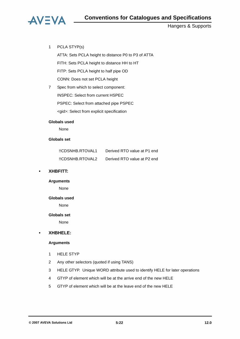
1 PCLA STYP(s)
For tube ATTAs, single value (quoted if using TANS)
For component ATTAs, space or / separated list for TEE, ELBO, BEND components
(NONE if not applicable)
2 Any other selectors (quoted if using TANS)
3 COMP or TUBE
4 Hanger Direction p-point (for TUBE). This p-point will be orientated to point in thedirection of the hanger Rotation Direction p-point (for COMP). This p-point will beorientated to point in the perpendicular direction of BENDs or ELBOs.
5 Angle flag. True if the component has a DDANG which needs to be deduced.
6 Connection/Fitting instructions:
12.0 5:21© 2007 AVEVA Solutions Ltd
Conventions for Catalogues and SpecificationsHangers & Supports
Globals used
None
Globals set
• XHBFITT:
Arguments
None
Globals used
None
Globals set
None
• XHBHELE:
Arguments
ATTA: Sets PCLA height to distance P0 to P3 of ATTA
FITH: Sets PCLA height to distance HH to HT
FITP: Sets PCLA height to half pipe OD
CONN: Does not set PCLA height
7 Spec from which to select component:
INSPEC: Select from current HSPEC
PSPEC: Select from attached pipe PSPEC
<gid>: Select from explicit specification
!!CDSNHB.RTOVAL1 Derived RTO value at P1 end
!!CDSNHB.RTOVAL2 Derived RTO value at P2 end
1 PCLA STYP(s)
1 HELE STYP
2 Any other selectors (quoted if using TANS)
3 HELE GTYP. Unique WORD attribute used to identify HELE for later operations
4 GTYP of element which will be at the arrive end of the new HELE
5 GTYP of element which will be at the leave end of the new HELE
12.0 5:22© 2007 AVEVA Solutions Ltd

Conventions for Catalogues and SpecificationsHangers & Supports
Globals used
Globals set
N.B. If argument 4 identifies an element which occurs later in the hanger'smembers list than argument 5, this will cause the new element to be created in‘backwards’ mode. This can be very useful in some circumstances
6 Arrive p-point/Leave p-point (e.g. 2/1)
7 Connection/Fitting instructions:
FIT: Fit the HELE into the available space (by setting HEIGHT attribute)
CONN: Connect the HELE to the previous element (or HH/HT)
DIST: Set the HELE at a specified distance from the previous element
PROP: Set the HELE at a specified proportional distance between the previous andthe next elements
DIST and PROP both have the format <keyword> <value> <p-point> (the p-pointdesignation is optional and defaults to P0)
8 Angle flag. True if the component has a DDANG which needs to be deduced.
9 Specification from which to select component:
INSPEC: Select from current HSPEC
PSPEC: Select from attached pipe PSPEC
<gid>: Select from explicit specification
!!CDSNHB.RINS1 Rod insertion length at P1
!!CDSNHB.RINS2 Rod insertion length at P2
!!CDSNHB.RTOVAL1 Derived RTO value at P1 end
!!CDSNHB.RTOVAL2 Derived RTO value at P2 end
1 HELE STYP
12.0 5:23© 2007 AVEVA Solutions Ltd

Conventions for Catalogues and SpecificationsHangers & Supports
• XHBHORI:
Arguments:
Globals used:
Globals set:
• XHBSCLA:
Arguments
1 HELE GTYP
2 Mode FORW or BACK
3 Connection/Fitting instructions
FIT: Fit the HELE into the available space (by setting HEIGHT attribute)
CONN: Connect the HELE to the previous element (or HH/HT)
DIST: Set the HELE at a specified distance from the previous element
PROP: Set the HELE at a specified proportional distance between the previousand the next elements
DIST and PROP both have the format <value> {<p-point>}
The default p-point is P0.
4 Angle Flag to direct component arrive/leave
!!CDSNHB.RINS1 Rod Insertion Length at P1
!!CDSNHB.RINS2 Rod Insertion Length at P2
!!CDSNHB.RTOVAL1 Derived RTO value for component (P1-Rod End)
!!CDSNHB.RTOVAL2 Derived RTO value for component (P2-Rod End)
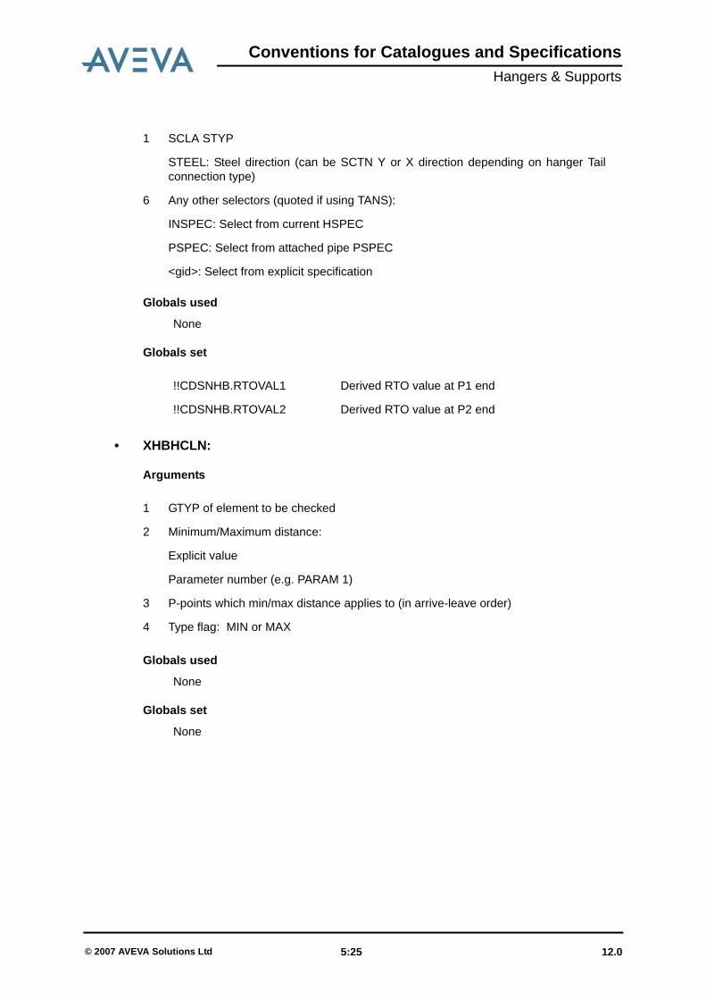
1 SCLA STYP
2 Any other selectors (quoted if using TANS)
3 Fit flag. True if SCLA is to be fitted into the available space.
4 P-point to orientate towards previous component. The subroutine will attempt toalign the PA/PL, but if this in insufficient, then it will use this p-point. Defaultorientation is determined by argument 5.
5 Default orientation:
TUBE: Pipe flow direction
12.0 5:24© 2007 AVEVA Solutions Ltd
Conventions for Catalogues and SpecificationsHangers & Supports
Globals used
None
Globals set
• XHBHCLN:
Arguments
Globals used
None
Globals set
None
STEEL: Steel direction (can be SCTN Y or X direction depending on hanger Tailconnection type)
6 Any other selectors (quoted if using TANS):
INSPEC: Select from current HSPEC
PSPEC: Select from attached pipe PSPEC
<gid>: Select from explicit specification
!!CDSNHB.RTOVAL1 Derived RTO value at P1 end
!!CDSNHB.RTOVAL2 Derived RTO value at P2 end
1 SCLA STYP
1 GTYP of element to be checked
2 Minimum/Maximum distance:
Explicit value
Parameter number (e.g. PARAM 1)
3 P-points which min/max distance applies to (in arrive-leave order)
4 Type flag: MIN or MAX
12.0 5:25© 2007 AVEVA Solutions Ltd

Conventions for Catalogues and SpecificationsHangers & Supports
• XHBSPAC
Arguments:
Globals used
None
Globals set
None
5.2.3 Hanger Configuration SpecificationsHanger configuration specifications should have their purpose set to HCFG, the DESC setto indicate the configuration type (see below), and the first question set to TYPE. Theanswer refers to the type of pipe element which the hanger will attach to. For tubeconfigurations, the TANS will be ANY (because an LSTU can occur after any component)and for component types, there will be a selector for each type (TEE, BEND or ELBO). Thenext question must be GTYP, which represents the generic type of the configuration(Welded, Base Mounted, etc.). The description is put into the TANS attribute of the nextselector. The next question should be PBOR, so that the configuration specification candetermine a list of configurations which can be applied to the current hanger. The lastquestion should be STYP, and represents the actual configuration. The description is putinto the TANS attribute of the relevant SPCO.
There are three types of hanger configuration specification:• Template Configurations which have a fixed length and can be used to determine the
positions of support steel when creating a steelwork template• Tube Configurations which have variable length which can be applied to tube type
hangers.• Component Configurations which have variable or fixed length which can be applied
to component type hangers.
Support Configurations
Support configurations store the following data:
1 Arrive end GTYP
2 Leave end GTYP (or HT)
12.0 5:26© 2007 AVEVA Solutions Ltd
Conventions for Catalogues and SpecificationsHangers & Supports
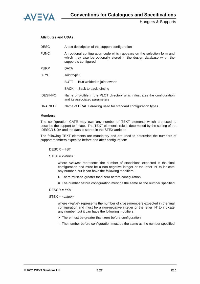
Attributes and UDAs
Members
The configuration CATE may own any number of TEXT elements which are used todescribe the support template. The TEXT element's role is determined by the setting of the:DESCR UDA and the data is stored in the STEX attribute.
The following TEXT elements are mandatory and are used to determine the numbers ofsupport members expected before and after configuration:
DESC A text description of the support configuration
FUNC An optional configuration code which appears on the selection form andwhich may also be optionally stored in the design database when thesupport is configured
PURP DATA
GTYP Joint type:
BUTT - Butt welded to joint owner
BACK - Back to back jointing
:DESINFO Name of plotfile in the PLOT directory which illustrates the configurationand its associated parameters
DRAINFO Name of DRAFT drawing used for standard configuration types
DESCR = #ST
STEX = <value>
where <value> represents the number of stanchions expected in the finalconfiguration and must be a non-negative integer or the letter ‘N’ to indicateany number, but it can have the following modifiers:
> There must be greater than zero before configuration
= The number before configuration must be the same as the number specified
DESCR = #XM
STEX = <value>
where <value> represents the number of cross-members expected in the finalconfiguration and must be a non-negative integer or the letter ‘N’ to indicateany number, but it can have the following modifiers:
> There must be greater than zero before configuration
= The number before configuration must be the same as the number specified
12.0 5:27© 2007 AVEVA Solutions Ltd

Conventions for Catalogues and SpecificationsHangers & Supports
Each type of member enumerated above must be described by another TEXT element:
DESCR = <member type>_<member number>
where <member type> is XM or ST and <member number> is the number ofthe stanchion/cross-member being described
STEX = <start connection info> <end connection info>
where <start connection info> takes the form
S:<member at start>/<joint position>/<Attached or Owner>:<clearancecode>
and <end connection info> takes the form
E:<member at end>/<joint position>/<joint ownership>:<clearance code>
<member at start> is a support member identifier of the start connection
<member at end> is a support member identifier of the end connection
Member identifiers can have the following forms:
<value> For a specific member number
N Representing the Nth member
< The most extreme ST/XM member in the XM/ST direction
> The least extreme ST/XM member in the XM/ST direction
<joint position> can take one of the following values:
Z At whatever ZDIST is required by the current position of the member
S At the start of the member
E At the end of the member
<joint ownership> is either of:
A Attached
B Owner
<clearance code> refers to the minimum clearance between the nearest pipeand the respective end as defined in the clearance data table:
A Perpendicular joint at end
B Free end
C Angled (brace) joint at end
A final TEXT element stores data about the parameters, as follows
DESCR = PARAM
12.0 5:28© 2007 AVEVA Solutions Ltd
Conventions for Catalogues and SpecificationsHangers & Supports
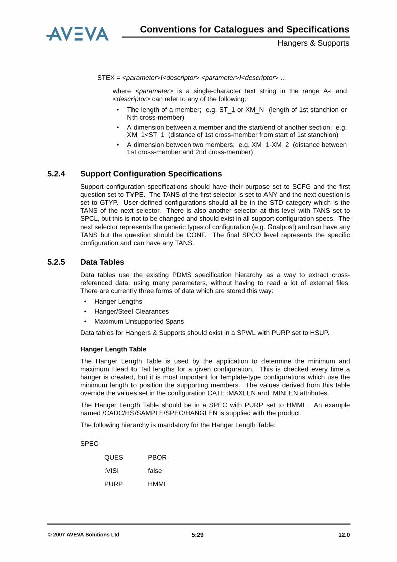
5.2.4 Support Configuration SpecificationsSupport configuration specifications should have their purpose set to SCFG and the firstquestion set to TYPE. The TANS of the first selector is set to ANY and the next question isset to GTYP. User-defined configurations should all be in the STD category which is theTANS of the next selector. There is also another selector at this level with TANS set toSPCL, but this is not to be changed and should exist in all support configuration specs. Thenext selector represents the generic types of configuration (e.g. Goalpost) and can have anyTANS but the question should be CONF. The final SPCO level represents the specificconfiguration and can have any TANS.
5.2.5 Data TablesData tables use the existing PDMS specification hierarchy as a way to extract cross-referenced data, using many parameters, without having to read a lot of external files.There are currently three forms of data which are stored this way:
• Hanger Lengths• Hanger/Steel Clearances• Maximum Unsupported Spans
Data tables for Hangers & Supports should exist in a SPWL with PURP set to HSUP.
Hanger Length Table
The Hanger Length Table is used by the application to determine the minimum andmaximum Head to Tail lengths for a given configuration. This is checked every time ahanger is created, but it is most important for template-type configurations which use theminimum length to position the supporting members. The values derived from this tableoverride the values set in the configuration CATE :MAXLEN and :MINLEN attributes.
The Hanger Length Table should be in a SPEC with PURP set to HMML. An examplenamed /CADC/HS/SAMPLE/SPEC/HANGLEN is supplied with the product.
The following hierarchy is mandatory for the Hanger Length Table:
STEX = <parameter>/<descriptor> <parameter>/<descriptor> ...
where <parameter> is a single-character text string in the range A-I and<descriptor> can refer to any of the following:
• The length of a member; e.g. ST_1 or XM_N (length of 1st stanchion orNth cross-member)
• A dimension between a member and the start/end of another section; e.g.XM_1<ST_1 (distance of 1st cross-member from start of 1st stanchion)
• A dimension between two members; e.g. XM_1-XM_2 (distance between1st cross-member and 2nd cross-member)
SPEC
QUES PBOR
:VISI false
PURP HMML
12.0 5:29© 2007 AVEVA Solutions Ltd

Conventions for Catalogues and SpecificationsHangers & Supports
Hanger Clearance Table
This table is used at two stages during the creation of a support (with steelwork). First wheninitially applying a configuration to deduce the lengths of the supporting members, andagain when the profiles have been selected to maintain the minimum clearance betweenhanger attachment points and supporting member ends. There are three types of clearancecode, depending on the type of joint at the member end:
DESC <optional text description>
1st Level of SELE
ANS <pipe nominal bore>
QUES SMAT
2nd Level of SELE
TANS <steel material code> *
QUES PMAT
3rd Level of SELE
TANS <pipe material code> *
QUES HTYP
SPCO level
ANS <length type code> **
TANS <hanger configuration type code> ***
COMM <min length>/<max length> (including units, e.g. 0mm/60mm)
* Material codes are defined in the application defaults from theSettings>Admin>Materials menu option.
** This can be set to 0 or 1:
1 - Lengths are calculated from outside of pipe. This is the default mode if aconfiguration is not defined in the Hanger Length Table.
0 - Lengths are calculated from the C/L of the pipe. In this mode, the applicationselects the PCLA to calculate the minimum length when creating supporttemplates
*** Code corresponds to the Hanger Build Macro suffix and the GTYP of theconfiguration CATE.
A1 Free end (no joint) before profiles set
A2 Free end after profiles set
B Perpendicular joint
12.0 5:30© 2007 AVEVA Solutions Ltd
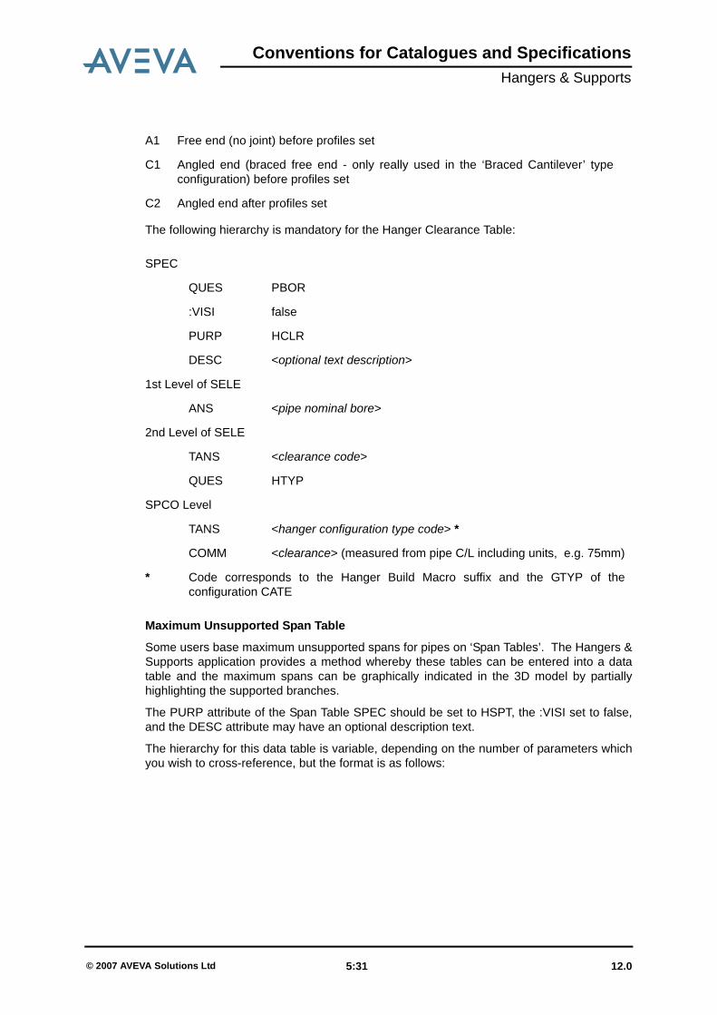
Conventions for Catalogues and SpecificationsHangers & Supports
The following hierarchy is mandatory for the Hanger Clearance Table:
Maximum Unsupported Span Table
Some users base maximum unsupported spans for pipes on ‘Span Tables’. The Hangers &Supports application provides a method whereby these tables can be entered into a datatable and the maximum spans can be graphically indicated in the 3D model by partiallyhighlighting the supported branches.
The PURP attribute of the Span Table SPEC should be set to HSPT, the :VISI set to false,and the DESC attribute may have an optional description text.
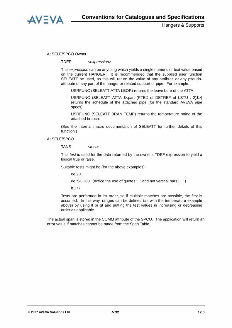
The hierarchy for this data table is variable, depending on the number of parameters whichyou wish to cross-reference, but the format is as follows:
C1 Angled end (braced free end - only really used in the ‘Braced Cantilever’ typeconfiguration) before profiles set
C2 Angled end after profiles set
SPEC
QUES PBOR
:VISI false
PURP HCLR
DESC <optional text description>
1st Level of SELE
ANS <pipe nominal bore>
2nd Level of SELE
TANS <clearance code>
QUES HTYP
SPCO Level
TANS <hanger configuration type code> *
COMM <clearance> (measured from pipe C/L including units, e.g. 75mm)
* Code corresponds to the Hanger Build Macro suffix and the GTYP of theconfiguration CATE
A1 Free end (no joint) before profiles set
12.0 5:31© 2007 AVEVA Solutions Ltd
Conventions for Catalogues and SpecificationsHangers & Supports
The actual span is stored in the COMM attribute of the SPCO. The application will return anerror value if matches cannot be made from the Span Table.
At SELE/SPCO Owner
TDEF <expression>
This expression can be anything which yields a single numeric or text value basedon the current HANGER. It is recommended that the supplied user functionSELEATT be used, as this will return the value of any attribute or any pseudo-attribute of any part of the hanger or related support or pipe. For example:
USRFUNC (SELEATT ATTA LBOR) returns the leave bore of the ATTA.
USRFUNC (SELEATT ATTA $<part (RTEX of DETREF of LSTU , 2)$>)returns the schedule of the attached pipe (for the standard AVEVA pipespecs).
USRFUNC (SELEATT BRAN TEMP) returns the temperature rating of theattached branch.
(See the internal macro documentation of SELEATT for further details of thisfunction.)
At SELE/SPCO
TANS <test>
This test is used for the data returned by the owner's TDEF expression to yield alogical true or false.
Suitable tests might be (for the above examples):
eq 20
eq 'SCH80' (notice the use of quotes '...' and not vertical bars |...| )
lt 177
Tests are performed in list order, so if multiple matches are possible, the first isassumed. In this way, ranges can be defined (as with the temperature exampleabove) by using lt or gt and putting the test values in increasing or decreasingorder as applicable.
12.0 5:32© 2007 AVEVA Solutions Ltd
AVEVA
Numerics2D Geometry Set 43D Geometry Set 3AAdministrative Elements 1, 2Attconn 6Automatic Drawing Production 3BBores 1British Standards 4BS 5950 1CCatalogues and Specifications Reference Manual 2CHOOSE 4Clearance code 30Component Configurations 26Component Point Sets 1Conventions for structural catalogues 1CSTANdard 1DDatakeys 2Datasets 4, 2Densities 16DENSITY.DAT 15, 16Detail Texts 2DIN 5FFittings catalogue 5HHanger Build Macros 20Hanger Clearance Table 30Hanger Length Table 29Hash character 16IISOCAT 4JJoints catalogue 6LLSRO 1MMaterial codes 30Material Texts 2Material World 15

AVEVA
MATR 15Maximum Unsupported Span Table 31Member identifiers 28Members 20, 27NNaming Conventions 4Negative Geometry Sets 4OOwnconn 6PPBOR 1Pipe Clamps 1Point sets 3, 4Profile catalogue 4Properties DB 15RRod take-out values 3SSample Catalogue 1Specification Reference 19Steel Clamps 1Structural Category 2Structural Section 2Subframe 19Subroutines 21Support Configurations 26TTabulated format 10TANS 26Tanswers 10Template Configurations 26Template-type configurations 29Toolkit 20Tube Configurations 26UUser-defined configurations 29VVariable Height Components 1