Embed Size (px)
Citation preview

DESIGN AND REALIZATION OF A STEP MOTOR DRIVER WITH MICRO-STEPPING CAPABILITY
A THESIS SUBMITTED TO THE GRADUATE SCHOOL OF NATURAL AND APPLIED SCIENCES
OF MIDDLE EAST TECHNICAL UNIVERSITY
BY
EMEL HĐZAL ATEŞ
IN PARTIAL FULFILLMENT OF THE REQUIREMENTS FOR
THE DEGREE OF MASTER OF SCIENCE IN
ELECTRICAL AND ELECTRONICS ENGINEERING
MAY 2011

Approval of the thesis:
DESIG AD REALIZATIO OF A STEP MOTOR DRIVER WITH MICRO-
STEPPIG CAPABILITY
submitted by EMEL HĐZAL ATEŞ in partial fulfillment of the requirements for the
degree of Master of Science in Electrical and Electronics Engineering, Middle East
Technical University by,
Prof. Dr. Canan Özgen ______________
Dean, Graduate School of atural and Applied Sciences
Prof. Dr. Đsmet Erkmen ______________
Head of Department, Electrical and Electronics Engineering
Prof. Dr. Mirzahan Hızal ______________
Supervisor, Electrical and Electronics Engineering Dept., METU
Examining Committee Members
Prof. Dr. Ahmet Rumeli ______________
Electrical and Electronics Engineering Dept., METU
Prof. Dr. Mirzahan Hızal ______________
Electrical and Electronics Engineering Dept., METU
Prof. Dr. Muammer Ermiş ______________
Electrical and Electronics Engineering Dept., METU
Prof. Dr. Osman Sevaioğlu ______________
Electrical and Electronics Engineering Dept., METU
Msc. Arif Yılmaz ______________
TÜBĐTAK UZAY
Date: 02.05.2011

iii
I hereby declare that all information in this document has been obtained and presented in accordance with academic rules and ethical conduct. I also declare that, as required by these rules and conduct, I have fully cited and referenced all material and results that are not original to this work.
ame, Last name : Emel Hizal Ateş
Signature :

iv
ABSTRACT
DESIG AD REALIZATIO OF A STEP MOTOR DRIVER WITH MICRO-
STEPPIG CAPABILITY
Hizal Ateş, Emel
M.Sc., Department of Electrical and Electronics Engineering
Supervisor: Prof. Dr. Mirzahan Hızal
May 2011, 69 pages
Step motors are motion control mechanisms that convert digital pulses into mechanical
shaft rotation. They provide high precision positioning and repeatability of movement
without a closed loop control, which is preferable for industrial applications in which
accurate positioning control is needed. In this thesis, design and realization of a step motor
driver will be performed using micro-stepping, which is based on controlling the current of
each winding of the motor continuously and solves noise and resonance problems as well as
providing an increase in accuracy and resolution.
Keywords: micro-stepping, microcontrollers

v
ÖZ
MĐKRO-ADIMLAMA YETEEKLĐ BĐR ADIMLI MOTOR SÜRÜCÜÜ
TASARIM VE GERÇEKLEŞTĐRĐMĐ
Hizal Ateş, Emel
Yüksek Lisans, Elektrik-Elektronik Mühendisliği Bölümü
Tez Yöneticisi: Prof. Dr. Mirzahan Hızal
Mayıs 2011, 69 sayfa
Adımlı motorlar, sayısal darbe işaretlerini mekanik mil dönüşlerine çeviren hareket denetim
mekanizmalarıdır. Yüksek doğruluklu konumlandırma gerektiren endüstriyel
uygulamalarda tercih edilir olan duyarlıklı konumlandırma ve geribeslemeli denetimsiz
hareket yinelenebilirliği sağlarlar. Bu tezde, motorun her sargısının akımını sürekli olarak
denetlemeye dayalı ve gürültü sorununu çözmekle birlikte duyarlık ve çözünürlükte artış
sağlayan mikro-adımlama kullanılarak bir adımlı motor sürücünün tasarımı ve
gerçekleştirimi yapılacaktır.
Anahtar Kelimeler: mikro-adımlama, mikrokontrolörler

vi
To My Beloved Husband

vii
ACKOWLEDGMETS
I would like to express my gratitude and deep appreciation to my supervisor Prof. Dr.
Mirzahan Hızal for his guidance and positive suggestions.
I am grateful to my family, my parents Fatma and Seyfettin and my sister Elif for their
support and love.
Finally, I would like to express my special thanks to my husband, Tuğrul, for his precious
help, great support and understanding. I believe without him this work would hardly be
possible. This thesis is dedicated to him.

viii
TABLE OF COTETS
ABSTRACT ......................................................................................................................... IV
ÖZ ......................................................................................................................................... V
ACKNOWLEDGMENTS .................................................................................................. VII
TABLE OF CONTENTS .................................................................................................. VIII
LIST OF TABLES ............................................................................................................... XI
LIST OF FIGURES ............................................................................................................ XII
CHAPTERS ........................................................................................................................... 1
1. INTRODUCTION ..................................................................................................... 1
1.1 Scope .................................................................................................................. 2
1.2 Related Work ..................................................................................................... 2
1.3 Outline................................................................................................................ 5
2. STEP MOTOR THEORY .......................................................................................... 6
2.1 Basic Operation of Step Motors ......................................................................... 6
2.2 Types of Step Motors ....................................................................................... 10
2.2.1 Variable Reluctance Step Motors ............................................................ 10
2.2.2 Permanent Magnet Step Motors ............................................................... 11
2.2.3 Hybrid Step Motors .................................................................................. 12
2.3 Step Motor Winding Types .............................................................................. 13
2.3.1 Monofilar and Bifilar Winding ................................................................ 13
2.3.2 Unipolar and Bipolar Winding Drive ....................................................... 14
2.4 Step Motor Excitation Modes .......................................................................... 15
2.4.1 Wave Drive Excitation ............................................................................. 16

ix
2.4.2 Two-Phase On Excitation ........................................................................ 16
2.4.3 Half-Step Excitation ................................................................................. 17
2.4.4 Micro-Stepping ........................................................................................ 18
3. STEP MOTOR CONTROL METHODS ................................................................. 21
3.1 Position Control Methods ................................................................................ 22
3.2 Current Control Methods ................................................................................. 23
4. PROPOSED SYSTEM ............................................................................................ 27
4.1 Overall System ................................................................................................. 28
4.2 Full-Bridge Converters .................................................................................... 30
4.2.1 Topology and Operation .......................................................................... 30
4.2.2 Drive and Decay ...................................................................................... 31
4.2.3 Component Selection ............................................................................... 34
4.2.4 Simulation ................................................................................................ 37
4.3 Gate Drivers ..................................................................................................... 41
4.4 Digital Control ................................................................................................. 45
4.4.1 Microcontroller ........................................................................................ 45
4.4.2 Scope and Specifications ......................................................................... 45
4.4.3 Algorithm ................................................................................................. 47
4.5 Current Control Feedback ................................................................................ 49
5. EXPERIMENTS ...................................................................................................... 51
5.1 Experimental Setup .......................................................................................... 51
5.2 Waveform Measurements ................................................................................ 54
5.3 CNC Operation ................................................................................................ 58
6. CONCLUSIONS...................................................................................................... 62
6.1 Summary .......................................................................................................... 62
6.2 Discussions ...................................................................................................... 63
6.3 Future Work ..................................................................................................... 64

x
REFERENCES .................................................................................................................... 65

xi
LIST OF TABLES
TABLES
Table 1 Electrical characteristics of IRF640N. .................................................................... 37
Table 2 Source-drain ratings and characteristics of IRF640N. ............................................ 37
Table 3 Electrical characteristics of MUR420. .................................................................... 37
Table 4 Electrical characteristics of IR2110. ....................................................................... 42
Table 5 Absolute maximum ratings of IR2110. ................................................................... 42
Table 6 Step motors tested for driver operation. .................................................................. 51
Table 7 Results for positional accuracy tests with a CNC controller................................... 59
Table 8 Test results for the maximum load torques achieved before the test motor starts to
lose steps for micro-step resolution γ=32. .............................................................. 60
Table 9 Test results for the maximum load torques achieved before the test motor starts to
lose steps for micro-step resolution γ=8. ................................................................ 61

xii
LIST OF FIGURES
FIGURES
Figure 1 Cross sectional diagram of a 3-phase variable reluctance step motor. (a) Stator and
rotor teeth. (b) Winding arrangement. ...................................................................... 7
Figure 2 Rotor position at (a) excitation of phase-A, (b) some time after excitation of phase-
B and (c) stable position after excitation of phase-B. ............................................... 8
Figure 3 Full revolution of a step motor with a step angle of 30°. ........................................ 9
Figure 4 Cross sectional view of (a) a 4-phase variable reluctance step motor and (b) a 3-
phase variable reluctance step motor with two teeth on each pole. ........................ 11
Figure 5 Cross sectional diagram of a 4-phase permanent magnet step motor. (a) Stator
teeth and cylindrical magnet rotor and (b) winding arrangement. .......................... 12
Figure 6 (a) Teeth and magnetic structure of the rotor of a hybrid step motor. (b) Bifilar
windings of two phases of a 4-phase stator of a hybrid motor................................ 13
Figure 7 (a) Monofilar winding, unipolar drive, (b) Unipolar drive with a center-tap (c)
monofilar winding, bipolar drive and (d) bifilar winding, bipolar drive. ............... 14
Figure 8 Wave drive excitation sequence for a 3-phase step motor..................................... 16
Figure 9 Full-step excitation sequence for a 3-phase step motor. ........................................ 17
Figure 10 Rotor position at (a) excitation of phase-A and phase-C, (b) some time after
turning off phase-C and turning on phase-B and (c) stable position after excitation
of phase-A and phase-B. ......................................................................................... 17
Figure 11 Half-step excitation sequence for a 3-phase step motor. ..................................... 18
Figure 12 Micro-step excitation sequence for a 3-phase step motor. .................................. 19
Figure 13 Space vector representations of phase currents in a 1/8th micro-stepping
operation. ................................................................................................................ 20
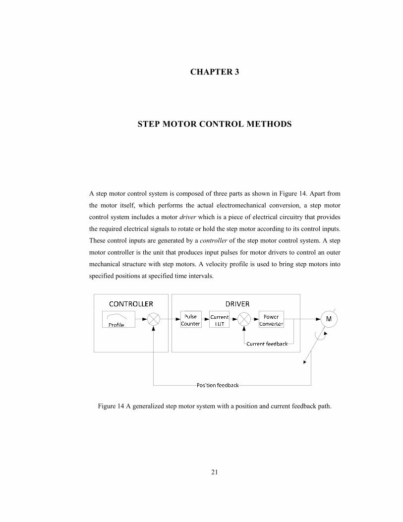
Figure 14 A generalized step motor system with a position and current feedback path. ..... 21
Figure 15 Control of motor current with a PWM chopper................................................... 24
Figure 16 (a) L/R drive circuit and (b) switching response of its output current. ................ 25
Figure 17 Block diagram of PI control. ............................................................................... 26
Figure 18 Overall motor driver system. ............................................................................... 28

xiii
Figure 19 (a) Natural steps in bipolar drive of a 2-phase hybrid step motor. (b) Winding
current waveform of both phases in bipolar wave drive and (c) bipolar micro-
stepping excitation of the same motor. ................................................................... 29
Figure 20 The full-bridge converter. .................................................................................... 30
Figure 21 Full-bridge decay modes corresponding to different PWM states. (a) Drive with
vo = +Vbus state and (b) its decay with vo = -Vbus state in two-state PWM. Different
decay modes in three-state PWM: (c) slow decay low diode re-circulation, (d) slow
decay low mosfet re-circulation, (e) slow decay high mosfet re-circulation and (f)
slow decay high diode re-circulation. ..................................................................... 33
Figure 22 Simplorer schematic of full-bridge circuit. .......................................................... 38
Figure 23 Duty cycle inputs of PWM blocks. ...................................................................... 38
Figure 24 Voltage waveforms on SPICE_D1 and SPICE_D2............................................. 39
Figure 25 Voltage waveforms on MOS1 and MOS2. .......................................................... 39
Figure 26 Voltage and current waveforms on the motor model. ......................................... 40
Figure 27 Sensing resistor voltage and current waveforms. ................................................ 40
Figure 28 Bootstrap configuration for IR2110. ................................................................... 43
Figure 29 Timing diagram of input commands. .................................................................. 46
Figure 30 Opto-coupler circuit for input command. ............................................................ 46
Figure 31 Flowcharts for (a) Main execution and (b) interrupt routine for microcontroller
software. .................................................................................................................. 48
Figure 32 Implemented step motor driver on PCB. ............................................................. 52
Figure 33 Experimental setup: step motor and load on the left, driver in the middle and the
power supply on the right. PC controller interface is seen in the front. .................. 52
Figure 34 Laboratory test setup with controller PC on the left and two different controller
interfaces on the right. The CNC drilling machine to operate is shown on the upper
right corner. ............................................................................................................. 53
Figure 35 Setup for positioning tests. .................................................................................. 53
Figure 36 Phase current waveforms for 128 micro-step resolution. Blue is phase-A and red
is phase-B. (a) Clockwise rotation under no load, (b) counter-clockwise rotation
under no load and (c) counter-clockwise rotation under fixed load........................ 55
Figure 37 Phase current waveforms for 64 micro-step resolution. Blue is phase-A and red is
phase-B. (a) 40rpm speed under no load, (b) 40rpm speed under fixed load and (c)
54rpm speed under load. ......................................................................................... 56

xiv
Figure 38 Phase current waveforms for 8 micro-step resolution. Blue is phase-A and red is
phase-B. (a) 320rpm rotation under no load and (b) 320 rpm rotation under fixed
load. ........................................................................................................................ 57
Figure 39 Load – speed curves for two different micro-stepping resolutions. .................... 61

1
CHAPTER 1
1. ITRODUCTIO
A step motor [1,2,3,4,5,6,7,8,9,10] is a type of brushless synchronous motor that generates
mechanical energy from discrete electrical pulses. Shaft of a step motor performs discrete
rotation movements with respect to the input electric signal. It is possible to drive a step
motor with digital signals directly from a computer or a microcontroller. In this manner,
step motor drive system can be regarded as a digital to angular position converter. Along
with the fact that its structure allows a simple control system, step motor has several
features that make it an ideal candidate as a positioning device.
• The speed and the amount of rotation are proportional to the frequency and number
of the input pulses. Thus, a wide rotational speed range can be achieved and precise
positioning is possible with small angular increments.
• Accurate operation can be provided with open loop control since positional error is
non-cumulative and the accuracy of a step motor is high, typically in the order of
5% of one step angle.
• Being a brushless motor, step motor is very reliable.
• Starting, stopping and reversing the device is easy.
There are also some disadvantages of using step motor. Some of which are:
• Resonances may occur at certain speed ranges.
• Step accuracy and resolution are directly dependent to the structure of the device
and can be a limiting factor for applications where high resolution is needed.
CHAPTERS

2
Micro-stepping [11,12,13] is a step motor driving method where input pulses are converted
to discrete estimations of the sinusoidal functions. This results in fractional input signals as
opposed to zero, full positive or full negative input signals used in commonly employed
full-step and half-step excitation methods. This method results in smoother operation with
less vibration and highly enhanced angular resolution of motor control; namely, minimizes
the effects of the disadvantages of step motors mentioned.
1.1 Scope
This thesis presents a step motor driver design with the aim of achieving micro-stepping
capabilities. Step motors are analyzed and different driving methods including several
possible control approaches are discussed. An electronic board for drive and control of a
hybrid step motor with adjustable user controls has been developed and used in experiments
to compare different driving strategies with respect to their electrical and mechanical
performances.
1.2 Related Work
Early studies on step motors are dated back to 1920’s [14]. Although the same motor
structure was known and used as an electromagnetic engine in the 19th century, a three-
phase variable reluctance step motor was introduced as a position control device in an
article named “The Application of Electricity in Warships” for the first time [4,14]. In this
article, a 3-phase variable reluctance step motor and a mechanical rotary switch that causes
motor to move in steps of 15° were described [4]. Inventions which enhanced step accuracy
and torque capability of step motors proceeded gradually [15,16] and the use of permanent
magnets in step motor structure was introduced in this period. Hybrid step motor, which is
widely used today, was invented, patented [17] and manufactured by General Electric
Company in 1952. First examples of this motor were used as synchronous motors running
at low speeds. However, hybrid motors have been used increasingly as a position control
device ever since. Especially, in 1960’s and 1970’s, evolving computer technology has also
led an improvement in step motor technology. Computer manufacturers, such as IBM, has
used step motors as actuators in terminal devices and promoted production of high
performance step motors.
In addition, as microprocessors become widespread, the use of step motors became easier
and more preferable due to the discrete nature.

3
Since the roots of step motor applications are found nearly a century earlier from now, it is
possible to observe almost all footsteps of the digital control history by reviewing step
motor drivers used throughout time. As mentioned before, first examples utilized to excite
step motors were manual mechanical switches. Later, with the invention of switching
devices such as thyratron gas tubes, more complicated and autonomous driver options have
become in use. A widespread implementation was an information storage application.
Operation instructions for numerically controlled machines were stored in the form of
perforations on tapes and a sensing device was used to convert the information on the tape
to the control signals for the switches. These switches were gradually replaced by thyristors
and transistors. With the appearance of the integrated circuits, the implementation of logic
circuit of drivers became simpler with lower costs.
Step motors are attractive and widely used in the industry due to their low price, simplicity
and low cost driver solutions. There are various alternatives to implement the power
converter block of a driver, partly or whole on-chip solutions are provided by various
manufacturers. L297-L298 IC’s from ST Microelectronics is among the classic and popular
driver solutions. In 2006, ST announced a new 65W fully integrated step motor driver IC
[18]. Ji et al. [19] proposes an application circuit utilizing DMOS full-bridge motor driver
IC LMD18245 [20] from National Semiconductor.
There are also highly sophisticated single chip solutions for driving step motors in the
market today. Allegro’s A3981 [21] and A4980 [22] and AMIS-30523 [23,24] from ON
Semiconductor (formerly AMI Semiconductor) are some examples of this type of drivers.
Although on chip solutions offer simple construction, a fully-functional drive circuitry with
a few external components; discrete driver solutions are still widely used. One reason for
this is that the maximum output power capability of the system is limited in on-chip
solutions. Power converter block constructed with discrete components gives more
flexibility in this case. Similarly, drive control logic circuitry options are also limited and
cannot be changed for most integrated driver IC’s. However, a PCB level driver with driver
logic being handled by a microcontroller device offers a flexible environment to improve
various driver algorithms.
The core component of a PCB level step motor driver is the processor where driver logic is
generated. Besides microcontrollers, DSP’s (Digital Signal Processor) are also widely used
as processors in step motor drivers. An application report from Texas Instruments describes
an implementation of a micro-stepping algorithm for TMS320F2808 DSPs [25]. Bellini et

4
al. [26] presents a micro-stepping implementation where a DSP is utilized as the processor
of the driver where a new pulse width modulation (PWM) method, which is called as
mixed-mode PWM, is proposed.
Field Programmable Gate Array (FPGA) based step motor driver solutions were also
implemented in recent years [27,13,28], although not as very widespread as
microcontrollers or DSP’s. Le and Jeon [27] propose an open-loop step motor driver based
on FPGA. Although FPGA based solutions are relatively a harder to implement and more
costly, their rationale is that FPGA based designs are compatible with Application Specific
Integrated Circuit (ASIC) conversion and thus they may be preferred. Another example to
FPGA based solutions is the work of A. Astarloa et al. [13] where they propose a step
motor control system which achieves the control of the micro-stepping resolution on-the-
fly; which most of the step motor driver systems cannot offer, by dynamically
reconfiguring block RAM in the FPGA used as the processor of the driver.
An application note from Microchip [29], introduces a step motor driver implementation
realized with a new generation PIC family, called the dsPIC. The study covers different
controlling schemes and micro-stepping options with several resolutions. Part of this thesis
is built upon the ideas presented in this application note.
Ran Zhang et al. [30] present a PIC18F2331 [31] based step motor driver with closed-loop
current control using micro-stepping method for a two-phase hybrid step motor. In this
study, a high and low side driver IR2110 [32] is used to drive the discrete power block
elements and cycle-by-cycle current limiting, a feature of the driver IC, is utilized to control
current output of the driver. The study presented in this paper matches with the design
presented in this thesis work on the grounds that parallel approaches are used and also
PIC18F4431 [31], a PIC in the same family with PIC18F2331, forms the core of the
realization of the driver presented in this thesis work.
Many other studies on step motor driving exist in the literature. Different driving
approaches exist for different step motor structures, such as linear motors [12]. A driving
scheme for 5-phase step motors is proposed in [33]. Step motor modeling is a major area
where Morar [34] discusses accurate simulation modeling of step motors. Closed-loop
positioning methods form another major area [35]. Brown et al. [7] introduce a damping
circuit to solve oscillation problems.

5
1.3 Outline
This thesis contains six chapters. Chapter 2 introduces step motors which are the
mechanical components to be driven with the driver circuitry and Chapter 3 provides a
discussion on step motor control methods. The proposed driver circuit is presented in
Chapter 4. Chapter 5 discusses experimental work and their results. Finally, Chapter 6 puts
forward conclusive remarks and future directions.

6
CHAPTER 2
2. STEP MOTOR THEORY
Step motors are brushless synchronous motors which perform a full rotation cycle in a fixed
number of steps. Theory of step motors deals with operability, physical structure and their
driving approaches along with electromechanical analysis of their operation.
This chapter deals with the fundamental ideas behind step motor theory. The discussion is
opened with the basic operation principle of step motors in the first section. The second
section introduces different types of step motors in use and different winding structures are
mentioned in the third section. Afterwards, several methods that are used to excite and
operate step motors are discussed. Micro-stepping method, a primary focus of this thesis, is
presented in this fourth and final section.
2.1 Basic Operation of Step Motors
Mechanical operation of step motors is possible with moving active parts with magnetic
force which is induced with discrete electrical signals. A basic type of step motor, called the
variable reluctance step motor, consists of stator and rotor parts made of ferromagnetic
material, such as steel. This section explains the principles of motion inside a simple 3-
phase variable reluctance motor in order to make an introduction to the basic concepts of
step motors. Different types of step motors and excitation modes are discussed in following
sections in more detail.
Basic structure of a variable reluctance step motor is shown in Figure 1. This motor has a
stator with six teeth and a rotor with four teeth and both parts are made of steel with high
permeability allowing high magnetic flux flowing through the structure. The stator is

7
wound in a 3-phase arrangement as shown in Figure 1 (b). Each phase (A, B or C) connects
two opposing stator teeth in series and induces a directed magnetic flux along the diameter
when excited.
In a simplified configuration, each phase of the stator is connected to the DC power source
through a switch. Phases of the stator are energized; in technical terms excited; in a
sequence by means of controlling the switches. Basic operation of the motor relies on the
principle that rotor aligns itself with the position where the magnetic reluctance is at
minimum and the magnetic flux produced is at maximum. This position is called
equilibrium position or rest position.
(a) (b)
Figure 1 Cross sectional diagram of a 3-phase variable reluctance step motor. (a) Stator and
rotor teeth. (b) Winding arrangement.
Figure 2 (a) shows the rest position of the rotor when only phase-A winding is excited. The
rotor is magnetized and aligned with the flux lines. If excitation switches from phase-A to
phase-B, magnetization of the rotor changes with new flux lines. In order to reduce the air
gap in which the magnetic flux occurs and reduce the Maxwell stress [36], the rotor starts
moving in counter-clockwise direction towards a position with lower reluctance as shown
in Figure 2 (b) and finally reaches the rest position as shown in Figure 2 (c).
A
A’
B’
C
C’
B
Phase C Phase B
Phase A
SB SA SC

8
(a) (b) (c)
Figure 2 Rotor position at (a) excitation of phase-A, (b) some time after excitation of phase-
B and (c) stable position after excitation of phase-B.
The amount of rotation of the step motor between two consecutive equilibrium positions in
two different phases is called the step angle. Step angle is related to the number of stator
phases (p) and rotor teeth () and its value is governed by (1). Thus the variable reluctance
motor having three phases and four rotor teeth, as depicted in Figure 1, has a step angle of
360º/(3·4) = 30º. The number of steps required for a full rotation of rotor back to its initial
position, or the step number, is 12 in this case.
= 360° ∙
(1)
The flux lines flow downwards when the stator windings of phase-A is excited and phase-B
and phase-C are switched off. This causes the stator tooth at A magnetized to north pole
and the stator tooth at A’ magnetized to south pole. Similarly the rotor tooth pointing
upwards in cross-sectional representation is magnetized to south pole and the rotor tooth
pointing downwards is magnetized to north pole.
Consider the case where phase-A windings are arranged in a reverse manner so that the
induced magnetic flux flows upwards. In this case, pole configurations would reverse but
the rest position will not change. Thus, rotation direction or step size does not depend on
the direction of flux for this type of motor.

9
Figure 3 Full revolution of a step motor with a step angle of 30°.
I II III
IV V VI
VII VIII IX
X XI XII

10
A switch from phase-A to phase-B causes the rotor to rotate 30º counter-clockwise.
Similarly, a switch from phase-B to phase-C will cause the rotor to rotate 30º more degrees
to the same direction. A full revolution is completed in twelve steps as shown in Figure 3
where phase windings are excited in successive repetition. A small dot placed on the rotor
shaft indicates a reference mechanical angle.
A rotation in clockwise direction can be achieved by reversing the excitation order.
Successively switching from phase-A to phase-C, afterwards to phase-B and finally back to
phase-A will cause the rotor to rotate in the reverse direction with the same step size.
2.2 Types of Step Motors
The core idea in the operation principle of step motors is the fact that the rest position of the
rotor changes by a fixed angle amount when excitation switches from one phase to another.
This process is elaborated in the previous section with a variable reluctance motor which
consisted of ferromagnetic mechanical components only.
This section lists and describes different types of step motors according to their magnetic
structure and how magnetic flux triggers the motion of their rotors. Firstly, the variable
reluctance motors are discussed further and several different variants are given. The second
type of step motor is the permanent magnet motor, which utilizes permanent magnets to
perform electromechanical rotation. Finally, the hybrid step motors combine mechanical
and electromagnetic properties of the former two types to achieve higher torque within the
same physical volume.
2.2.1 Variable Reluctance Step Motors
Variable reluctance step motors consist of wired iron rotors and wound stators. In a
variable reluctance motor, stator poles are excited with DC input and rotor windings
become attracted and perform rotation. A 3-phase variable reluctance motor with six stator
teeth and four rotor teeth is presented in Figure 1.
A change in DC input from one phase to another changes the amount of actual air gap and
thus the amount of instantaneous reluctance present under magnetic flux lines. The step
motor reaches an equilibrium position when the rotor teeth under magnetic flux align with
the excited phase.
Step motors in use generally have step angles much lower than 30º. A lower step angle is
achieved by increasing the number of phases and rotor teeth. Figure 4 (a) shows a variable

11
reluctance step motor with eight stator teeth and six rotor teeth. A single step in this motor
results in 15º of rotation. This motor sacrifices ease of control with an additional electrical
phase in order to obtain a higher step number.
An alternative approach to increase the step number is using two or more teeth per pole. A
3-phase variable reluctance motor structure with 14 rotor teeth is given in Figure 4 (b). This
motor attains a step number of 42 and a step angle of 8.57º.
(a) (b)
Figure 4 Cross sectional view of (a) a 4-phase variable reluctance step motor and (b) a 3-
phase variable reluctance step motor with two teeth on each pole.
2.2.2 Permanent Magnet Step Motors
Permanent magnet step motors have cylindrical magnet rotors and single pole electrical
phases. When a phase is excited, magnetic flux occurs inducing north or south pole on a
single stator teeth, which in turn aligns the permanent magnet rotor inside. Illustration of a
permanent magnet step motor is shown in Figure 5.
The rotor of a permanent magnet motor stays at a detent position enforced by the magnetic
structure of the motor when no excitation is in place. This position can be different from the
rest position of the motor when any of the windings are excited.
Similar to a variable reluctance motor, rotation in a permanent magnet step motor is
realized by alternating excitation between consecutive phases. The rotor inside the motor
given in Figure 5 rotates clockwise when phase excitation order is A-B-C-D. Exciting the
stator winding in A-D-C-B order will result in a counter-clockwise motion. Step angle of
this motor is 90º. Step angle of permanent magnet motors can be decreased by introducing
more stator teeth and phases.
A
A’
C’
D’
B’
C
D
B A
A’
B’
C
C’
B

12
(a) (b)
Figure 5 Cross sectional diagram of a 4-phase permanent magnet step motor. (a) Stator
teeth and cylindrical magnet rotor and (b) winding arrangement.
The permanent magnet step motor, whose windings are shown in Figure 5, is excited with
unipolar winding excitation where current flows towards a single direction. In this
example, each stator teeth is excited to south pole with the windings coiled around. This
configuration results in an inefficient operation in terms of generated torque since opposing
stator teeth with respect to stator magnetization are not utilized. The alternative is the
bipolar winding excitation where stator windings can be excited in both directions. In this
configuration opposing stator teeth are excited to opposing poles, i.e. Pole C is magnetized
to north when pole A is magnetized to south, and the induced magnetic flux increases as
well as the generated torque per motor volume. In bipolar excitation, opposing poles are
regarded as a single phase and they are named such as A, B, A’ and B’ instead of A, B, C
and D. Detailed discussions on different winding configurations are given in the next
section.
2.2.3 Hybrid Step Motors
Hybrid step motors combine operation principles of both variable reluctance motors and
permanent magnet motors. In a typical hybrid step motor, the rotor structure is cylindrically
stacked into two more sections as shown in Figure 6 (a). Interior of the rotor is a cylindrical
permanent magnet with different poles in consecutive stacks and the teeth of the rotor are
laminated steel. Different stacks have a fractional tooth pitch difference.
Phase B
Phase A
SB SA SC
A
C
B D
S
Phase D
Phase C
SD

13
(a) (b)
Figure 6 (a) Teeth and magnetic structure of the rotor of a hybrid step motor. (b) Bifilar
windings of two phases of a 4-phase stator of a hybrid motor.
The stator structure of hybrid motors with misaligned rotor teeth are not different from
stator structures of other motor types covered so far. However, the windings are arranged in
bifilar scheme that allows induction of magnetic flux in both directions. Bifilar filing in a
two phase hybrid motor is shown in Figure 6 (b). In a hybrid step motor, during excitation
of phase A, both magnetic poles of the rotor become attracted and align to a specific
position. When excitation switches to phase-B, the rotor teeth become attracted in the
opposing direction and movement is realized in a specific direction designed by proper
teeth alignment.
Different variations of hybrid motors can be obtained either by using a permanent magnet
as the stator instead of the rotor or by enforcing teeth misalignment to stator stacks instead
of the rotor.
2.3 Step Motor Winding Types
2.3.1 Monofilar and Bifilar Winding
Each winding spans two opposing stator teeth in a variable reluctance motor which is
shown in Figure 1 and each winding spans a single stator teeth in a permanent magnet
motor which is shown in Figure 5. Each coil around a single stator tooth belongs to a single
phase in both motor types. This is called the monofilar winding scheme. Figure 1 (b) and
Figure 5 (b) shows examples of this winding type.
S
Phase A Phase B

14
Windings in a hybrid step motor share stator poles, in contrast to monofilar winding. Thus,
both magnetic poles can be realized on a single stator tooth. This is called the bifilar
winding scheme and an example is seen in Figure 6 (b).
Two coils wound around a single tooth are magnetically coupled when an excitation on any
of them is applied. This coupling allows better positioning than wiring these two coils
separately[4].
2.3.2 Unipolar and Bipolar Winding Drive
Same voltage polarity applied to monofilar windings will create a magnetic flux always in
the same direction. The stator tooth around which the coil is wound will have a single
magnetic polarity dictated by the winding orientation. This kind of excitation is called the
unipolar drive of the winding. A simple circuit for unipolar drive on a monofilar winding is
shown in Figure 7 (a). A transistor in series allows switching the excitation current on and
off.
(a) (b)
(c) (d)
Figure 7 (a) Monofilar winding, unipolar drive, (b) Unipolar drive with a center-tap (c)
monofilar winding, bipolar drive and (d) bifilar winding, bipolar drive.

15
Permanent magnet and hybrid step motors require attraction of both magnetic poles. Center
taps are used to achieve this with unipolar driven windings as shown in Figure 7 (b). A 2-
phase permanent magnet or hybrid step motor with a unipolar winding structure has five or
six wires, composed of two terminals for each winding and one combined or two center
taps respectively. These center taps are typically used as the positive supply side, and the
terminals of the windings are grounded. In this step motor winding configuration, two
switches are required, one for each half of the winding. Only a single half of the winding
can be excited at a time and the torque output reduces as a result.
Current on a monofilar winding can induce a magnetic flux in the opposing direction if it is
flowing through the coil in reverse. Selectively changing the flux direction, thus magnetic
polarity, can be achieved with the full-bridge converter given in Figure 7 (c) with four
transistors. This excitation technique is called the bipolar drive of the monofilar winding.
The full-bridge topology is discussed in Chapter 4.
The winding structure of bipolar step motor does not have center taps. A 2-phase permanent
magnet or hybrid step motor with a bipolar winding structure has four wires as shown in
Figure 7 (c). In this configuration, the whole winding can be energized at once as opposed
to the unipolar drive with a center tap. As a result, the torque capability of the motor can be
fully utilized. However, the bipolar drive circuitry is more complex than the unipolar
driving circuitry.
Finally, the bifilar winding method allows inducing magnetic flux in any direction by
selectively exciting one of the coupled coils. Bipolar drive of the bifilar scheme is shown in
Figure 7 (d).
2.4 Step Motor Excitation Modes
In the examples given so far, only one phase of any step motor is excited at any time during
rotation. In this section different phase excitation approaches are presented. First of all, the
basic method of wave drive excitation is given and it is followed by two-phase on
excitation, which is an alternative to produce full steps. The discussion continues with half
step excitation, which doubles the effective step number and thus increases the positional
accuracy. Finally, micro-stepping excitation, which is the most important of all regarding
this thesis, is explained.

16
2.4.1 Wave Drive Excitation
Wave drive excitation is the step motor excitation method where only a single phase
winding is excited at a time. All phases are excited one by one in an alternating sequence as
represented in Figure 8. In wave drive excitation, each clock rotates the rotor by one natural
step angle, θs. This makes wave drive a method for full-step excitation of the motor, since it
causes rotation in full steps. The sequence given in Figure 8 rotates a 3-phase variable
reluctance motor as shown in Figure 3.
Figure 8 Wave drive excitation sequence for a 3-phase step motor.
2.4.2 Two-Phase On Excitation
Two-phase on excitation is the step motor excitation method where two phase windings are
excited simultaneously at a time, as the name implies. This operation is also called full-step
excitation since it causes rotation in full natural steps. Similar to the wave drive, two-phase
on excitation is a full step operation. The polarity of the input is reversed for one of the
phases each time to trigger a new step. This results in full rated torque. The excitation
sequence for a 3-phase motor is given in Figure 9.
A
B
C
pos
. cl
ock
0 1 2 3 4 5 6 7 8
0° 2 3 4 5 6 7 8

17
Figure 9 Full-step excitation sequence for a 3-phase step motor.
Excitation of two phases together provides a better transient response than exciting a single
phase only. The details of this phenomenon can be found in the fourth chapter of [4] where
further information on the dynamical analysis of one-phase on and two-phase on excitation
modes and comparison of their damping characteristics is given. Figure 10 shows the step
transition in two-phase on excitation from phases A and C to phases A and B of the variable
reluctance motor given in Figure 1.
(a) (b) (c)
Figure 10 Rotor position at (a) excitation of phase-A and phase-C, (b) some time after
turning off phase-C and turning on phase-B and (c) stable position after excitation of phase-
A and phase-B.
2.4.3 Half-Step Excitation
In half-step excitation, a step motor driver switches between two-phase on excitation and
wave drive excitation. The combined sequence for a three phase motor is shown in Figure
A
B
C
pos
. cl
ock
0 1 2 3 4 5 6 7 8
− 12
12
32
52
72
92
112
132
152

18
11. All possible rotor positions from both wave drive excitation and two-phase on
excitation are available in half-step excitation, reducing the effective step angle to half. This
operation results in higher angular precision but lower torque.
Figure 11 Half-step excitation sequence for a 3-phase step motor.
2.4.4 Micro-Stepping
This thesis focuses on micro-stepping excitation method, which is based on subdividing
one natural step of a step motor into many small steps with use of electronics [3,4].
In traditional drives, stator phases are excited with discrete pulses [26]. This type of
excitation brings some limitations to the motor operation. One limitation is, step size,
therefore system position accuracy is generally bounded to the natural step size of the
motor, which is directly determined by the stator phases and rotor teeth count. Another
limitation is the poor dynamic torque characteristics. One way to overcome this problem is
to generate new intermediate equilibrium positions [26] to smoothen the motor operation.
An example to micro-step excitation sequence for a 3-phase step motor is shown in Figure
12.
In wave-drive and two-phase on excitation, step size is equal to the natural step size. In
half-step excitation, step number is doubled and step size is halved. This is achieved by
mixing equilibrium positions from the wave-drive and two-phase on methods. On the other
hand, micro-stepping method divides one full-step into a large number of smaller discrete
steps by continuously varying winding currents [37].
A
B
C
pos
. cl
ock
0 1 2 3 4 5 6 7 8
0° 12
32 2
52 3
72 4

19
Figure 12 Micro-step excitation sequence for a 3-phase step motor.
Assuming an ideal micro-stepping drive system by neglecting the non-linear effects of both
the motor and the driving circuitry, currents of a two-phase hybrid step motor can be
represented as a space vector [38,26] given in (2). Amplitude of the resultant current vector
i remains constant and is equal to I if phase currents are chosen as in (3) and (4) where θe is
the electrical position and I is the current amplitude per phase.
= + (2)
= sin " (3)
= cos " (4)
As shown in Figure 13, produced torque of the motor will be constant over the full
operation cycle since torque is directly proportional to current. In other words, the torque
behavior under sinusoidal excitation and the full step equilibrium position will be the same.
Thus, it is at least theoretically possible to obtain infinitely many intermediate equilibrium
positions [38,26]. However in practice, non-linear factors of the system bring restrictions on
the number of micro-steps achievable and also introduce difficulties in achieving constant
current and torque outputs. Yet, micro-stepping method can significantly improve system
performance.
A
B
C

20
Figure 13 Space vector representations of phase currents in a 1/8th micro-stepping
operation.
7/8 step
1/8 step
5/8 step
6/8 step
Full step
2/8 step
3/8 step
4/8 step
A
B Current Percentage
Cur
rent
Per
cent
age
100%
100%
Constant
Torque
21
CHAPTER 3
3. STEP MOTOR COTROL METHODS
A step motor control system is composed of three parts as shown in Figure 14. Apart from
the motor itself, which performs the actual electromechanical conversion, a step motor
control system includes a motor driver which is a piece of electrical circuitry that provides
the required electrical signals to rotate or hold the step motor according to its control inputs.
These control inputs are generated by a controller of the step motor control system. A step
motor controller is the unit that produces input pulses for motor drivers to control an outer
mechanical structure with step motors. A velocity profile is used to bring step motors into
specified positions at specified time intervals.
Figure 14 A generalized step motor system with a position and current feedback path.

22
Input pulses brought to a step motor driver are used to control the number of steps or micro-
steps to apply to the motor. Generally, these input pulses are converted into iterations using
a look-up-table, which stores the amount of current to supply to each phase of the motor in
a micro-stepping application.
The first section of this chapter deals with the methods used in controlling the position of
the step motor whereas the second section deals with the types of current control methods
of the motor driver. These methods are associated with the position and current feedback
loops, which are shown in Figure 14.
3.1 Position Control Methods
Step motors perform rotation by switching between equilibrium positions. Rotor position is
known to the driver at any time if the initial position is known and the motor is operating
properly under no load. Thus, it is possible to drive a step motor by directly sending
appropriate electrical signals to bring the rotor into a specific position without using a
position feedback loop. This technique is called the open loop position control of the step
motor.
A load which is connected to the shaft of the step motor can manipulate the rotor position if
it applies an amount of torque that is higher than the equilibrium torque, which is caused by
the magnetization from stator windings at an equilibrium position. If the load range is small
enough, open loop control can still be utilized by increasing the equilibrium torque to
compensate for the load. On the other hand, accurate positioning under a wide range of
loads can be achieved by closed loop position control of the step motor where rotor position
is converted to electrical signals by a sensing mechanism and returned to the controller with
a feedback path. The controller can respond to the load by adjusting the speed until the
rotor comes to a desired position.
In a closed loop position control system, instantaneous rotor position is measured and fed
back to the system during operation. Thus, the synchronism is ensured continuously
between step commands of the controller and rotor position. The system processes the next
command after the controller receives the information that the former step is completed and
hence the rotational acceleration of the rotor is adjusted automatically.
Acarnley [39] proposes two methods for position detection mechanism which are optical
detection of rotor position and waveform detection. Optical position detection is based on

23
utilizing an optical encoder, which is a directly connected to the rotor shaft, measures the
angular displacement of the shaft and converts this information to a proper electrical signal.
Drawbacks of this method are the additional cost of encoder and additional mechanical
connections introduced to the system. Waveform detection overcomes both of these
drawbacks by monitoring the phase currents of each phase of the motor and analyzing their
waveforms [39].
Closed loop systems are superior to the open loop systems when utilization of the torque
capacity of the system is considered since it is necessary to use a closed loop system in
order to run the system in full torque capacity without stalling the motor. On the other hand,
the reason why step motors are popular in the market is their ability to operate without a
position control mechanism. For applications with light load requirements open loop
position control generally suffice.
3.2 Current Control Methods
The aim of current control is managing the power which is supplied to the step motor.
Similar to position control, current can be controlled in either an open loop or closed loop
fashion.
Open loop current control refers to the control of the step motor without measuring the
current flowing through the windings. One of the simplest of open loop control methods is
the fixed voltage control, which is preferred for systems where torque demand of the system
is not critical. Fixed voltage control method aims to provide a fixed amount of voltage,
which is generally the rated voltage, to drive the motor and current limitation is left to the
internal resistance of the motor [40]. Fixed voltage control is ideal if low noise operation is
needed and the system is operated under fixed conditions such as fixed motor speed or
fixed load [29].
In systems with a higher torque demand, fixed current control is employed where the motor
is operated around the rated current. Fixed current control method refers to open loop
current control as in the case in the fixed voltage control. This time, the voltage level
applied to the windings is increased. As a result, output current of the driver can reach to
the desired levels more rapidly and thus allows faster operation.
Current control can be implemented in various ways. One approach is directly applying the
rated voltage to the phase windings in a sequence in accordance with the desired excitation

24
mode. This is the method mentioned as fixed voltage control. Another option is using a
power source with a higher voltage than the rated voltage of the motor. Stepping this
voltage down to the rated voltage is achieved either by applying linear control or by a pulse
width modulation (PWM) chopper [29,40] as shown in Figure 15.
Figure 15 Control of motor current with a PWM chopper.
The classical scheme of current limiting techniques, which is referred as L/R drive, was
commonly used and recommended until 1980’s to overcome the slew rate problem of
voltage control [40]. Slew rate problem is the inability of output current to instantaneously
settle after excitation due to the inductive nature of the motor.
The step motor can be modeled as a series L/R circuit. At the time of excitation, (5) and (6)
are valid where Lm and Rm are motor parameters and τ is the time constant of the circuit.
%& = '( ∙ ))* + +( ∙ (5)
, = '( +(
(6)
The more dominant the inductive behavior, the lower the slew rate of the output is. Time
constant of the drive is increased by adding a series resistor, as in (7) and (8).

25
%& = '( ∙ ))* + -+( + +"./0 ∙ (7)
, = '(-+( + +"./0 (8)
It is possible to have a higher bus voltage than in the former case. V’bus > Vbus is applied to
the windings. The new circuit with added Rext and the output current are given in Figure 16
(a) and (b) respectively.
Vbus‘ > Vbus
QL1
QH1
QL2
QH2
M
Rext
s
(a) (b)
Figure 16 (a) L/R drive circuit and (b) switching response of its output current.
Step motor systems that incur a varying amount of torque from their load can utilize closed
loop current control, where output current is measured and adjusted according to torque
demands. Closed loop current control offers a better performance compared to open loop
current control.
Closed loop current control can be achieved with peak detection [41] where the peak value
of the phase current over many steps is detected and regulated by adjusting the duty cycles
of the PWM signals accordingly. Achieving this type of regulation is possible with a PWM
chopper on a full-bridge topology [29]. A low starting reference value is selected and the
duty cycle of the PWM signal is gradually increased until the maximum measured current
value is equal to the rated current of the motor. The measured maximum current is sampled

26
for each electrical cycle and the fixed current control is implemented continuously. As a
result, motor performance under variable speed conditions significantly increases. This
method also has the advantage of operability with different step motor types. Prior tuning
specific to the motor type is not required [29].
It is also possible to adjust the whole shape of the current waveform with closed loop
current control where system measures the winding currents forces them to follow a
reference pattern.
PI control is a generic framework for process output manipulation and can be utilized for
matching step motor current to specific waveforms [29]. In a PI step motor controller
system, the difference, or error, between measured and desired instantaneous current, also
called the set-point, is collected and summed with its integral to generate a PI output as
shown in Figure 17. A negative PI output invokes an inhabitation of output current and a
positive output leads to a boost.
Figure 17 Block diagram of PI control.
A step motor driver utilizing a closed loop PI current controller can gradually adjust its
operation according to the PI block output, e.g. by altering the duty cycle of its PWM
generator [27]. Shutting off current supplies to the motor on negative PI output is another
option [30].

27
CHAPTER 4
4. PROPOSED SYSTEM
Step motors are devices that convert discrete electrical pulses into mechanical rotation. A
hybrid step motor, which combines the principles of both variable reluctance and
permanent magnet motors, is an efficient and widely utilized step motor type.
A step motor control system is composed of controller and driver parts. Motor controllers
are devices that drive a step motor according to a predefined velocity profile. On the other
hand, a step motor driver is responsible for the generation and timing of electrical pulses to
perform rotation as well as the driving of the current to energize the motor windings.
This chapter introduces the step motor driver circuit, which is designed and implemented as
part of this thesis. This driver performs the bipolar micro-step excitation of 2-phase hybrid
step motors.
Generation and timing of electrical pulses to generate motor steps are accomplished in a
functional unit which is called the digital control of the driver. These pulses are passed to
gate drivers, which shift the level of electrical inputs to operate a set of switches inside the
full-bridge converters introduced in Chapter 2. The full-bridge circuit drives the current for
the motor windings according to electrical pulse inputs.
The overall view of the whole driver system is introduced in the first section to provide a
general discussion on the problem. The chapter continues with the full-bridge converter in
the second section, with the gate driver in the third section and with the digital control
counterpart in the fourth section. The fifth section deals with the closed-loop current control
in this driver.

28
4.1 Overall System
Step motor driver system implemented in this thesis is divided into three components.
Digital control generates the logical signals that form a micro-stepping waveform. These
signals are converted electrical levels for transistor gate switches by gate drivers. Finally, a
full-bridge converter is used to drive each phase of the step motor. Overall architecture is
summarized in Figure 18.
Figure 18 Overall motor driver system.
Hybrid step motors introduced in Chapter 2 are efficient and compact step motor types. A
hybrid step motor is implemented by stacking different rotor or stator poles on a single
shaft. Motor size is reduced by allowing bipolar drive, i.e. the ability to excite motor
windings in both directions. Bipolar excitation of a 2-phase hybrid step motor results in
four distinct step pulses as shown in Figure 19 (a) where θs is the natural step angle.
Winding currents of Phase-A and Phase-B follow the patterns given in Figure 19 (b).
Micro-stepping, discussed in Chapter 2 can increase the positioning precision and accuracy
of the motor system by switching current from one phase to the other smoothly by
subdividing natural steps of the step motor. The waveforms given in Figure 19 (b) can be
converted to the sinusoidal forms as in Figure 19 (c) by micro-step excitation.
Micro-stepping resolution is the number of distinct excitation current configurations in a
micro-stepping drive. In other words, it is the number of micro-steps in full electrical input
pulse period, which contains four natural steps in bipolar drive of a 2-phase hybrid step
motor. The number of micro-steps needed for one natural step, µs, of the motor is given by
(9), where γ is the operation resolution.
1 = 24 (9)
Digital Control
Gate Drivers
Full Bridge Circuits
Step Motor

29
(a)
(b)
(c)
Figure 19 (a) Natural steps in bipolar drive of a 2-phase hybrid step motor. (b) Winding
current waveform of both phases in bipolar wave drive and (c) bipolar micro-stepping
excitation of the same motor.
A
B
A
B
A+
B+
A-
pos
. cl
ock
0 1 2 3 4 5 6 7 8
0° 2 3 4 5 6 7 8
B-

30
Full-bridge converters for each phase of the motor control the amount and direction of the
current flowing through the associated winding. Digital control and gate drivers supply the
switching inputs for the transistors in full-bridge circuits.
4.2 Full-Bridge Converters
4.2.1 Topology and Operation
The full-bridge converter is a topology that allows winding current to flow in both
directions and it is the typical driving circuitry for bipolar step motors. Full-bridge
converter has two legs as shown in Figure 20. Each leg contains two switches and two anti-
parallel diodes, also called catch diodes. The center points of the two legs are the output
ports of the bridge and connected to the load. Full-bridge circuitry is also called H-bridge.
Figure 20 The full-bridge converter.
The output voltage is given in (10) with respect to the node voltages given in Figure 20.
Each switch and its anti-parallel diode constitute a bi-directional path to the current to flow.
Thus, v17 and v37 are independent of the polarity of the output current and they can be
manipulated by only changing the state of the switches. The value of v17 and v37 can be
expressed by (11) and (12).
34 = 356 − 376 (10)
356 = 8%& ; :1 ;<=)>;*=? @=) :2 ABB0 ; :2 ;<=)>;*=? @=) :1 ABBC (11)
376 = 8%& ; :3 ;<=)>;*=? @=) :4 ABB0 ; :4 ;<=)>;*=? @=) :3 ABBC (12)

31
The average values of v17 and v37 are given in (13) and (14) where t1on is the on time and
t1off is the off time for S1, Ts is the full period time and D1 is the duty ratio of S1. The mean
value of vo is found as in (15).
356DDDDD = %& ∙ *14E + 0 ∙ *14FFG
= %& ∙ H5 (13)
376DDDDD = %& ∙ H7 (14)
34DDD = %& ∙ -H1 − H30 (15)
4.2.2 Drive and Decay
The driver implemented in this thesis uses PWM chopping for driving the phase winding
currents. PWM signals control the winding excitation of each phase where the duty cycle is
proportional to the absolute value of the current waveform at a single micro-step. A full-
bridge circuit for each phase ensures that during the on state of the PWM, phase windings
are energized and during the off state phase currents decay.
An important issue to note is that conducting of both the switches in a single leg creates a
short circuit between the voltage source and the ground and this must be avoided. To
prevent this, an additional toff time is introduced before one switch is turned on and after the
other one is turned off. This time is called blanking time or dead-time and necessary for
safe operation in cases where simultaneous switching is needed. In the analysis of vo dead-
time is neglected and it turned out to be directly proportional to the reference voltage
selected. However, dead-time brings nonlinearity to the system and in a practical bridge, vo
formulation is more complicated than presented here.
One technique to drive the bridge is turning S1 and S4 on while turning S2 and S3 off as the
first state, and in the second state turning S2 and S3 on while turning S1 and S4 off. This is
achieved by giving complementary PWM signals to the gate drive circuitries of S1-S4 and
S2-S3 switch pairs. In full-bridge terminology, this type of driving is referred as bipolar
driving mode, and the PWM scheme is called two-level PWM. Bipolarity achieved because
vo changes between two output voltage levels, +Vbus and -Vbus. Duration ratios of these two

32
states are D1 and D3, which determine the winding current from the average of voltage
chopper introduced in Chapter 3.
Another PWM technique is called the three-level PWM scheme. This name indicates the
+Vbus, -Vbus and zero level of vo can be obtained from (15). The third output state, vo = 0, can
be achieved when S1 and S3 are turned off while S2 and S4 are turned on or vice-versa.
This mode allows a passive decay of the current inside the windings. Current in positive
direction can be achieved by switching between vo = +Vbus and vo = 0 states. Current in the
opposite direction is achieved by switching between vo = -Vbus and vo = 0 states.
One typical difference between two-level PWM and three-level PWM is the rate of change
of output current, io during the operation. In two-level PWM scheme, io changes faster than
the three-level PWM scheme. This allows higher PWM frequency in the expense of higher
current ripple.
Several other different switching schemes can be applied on full-bridge converters besides
two-level and three-level PWM [42,43]. One method is based on mixing these two schemes
in order to benefit from the advantages of the two schemes to some extent. This method is
called mixed-mode PWM [26].
In step motor terminology, different PWM techniques are referred as decay modes since
they only differ in the switch configuration when the current inside the windings are
decaying. Two-level PWM scheme is called fast-decay. Three-level PWM corresponds to a
set of slow-decay modes. Slow-decay can be implemented in many ways. Some drive and
decay modes are shown in Figure 21. The states in two-state PWM are shown in Figure 21
(a) and (b). In these states, +Vbus and -Vbus is applied to the motor windings respectively,
thus one state can be used to decay the current driven by the other. Thus, a fast active decay
occurs. Figure 21 (c), (d), (e) and (f) show different variations of slow decay
implementation. In these operations, the motor winding is short circuited. All four of these
examples show the decay current that is driven previously by the drive shown in Figure 21
(a). Slow decay low mosfet re-circulation as shown in Figure 21 (d) is used as the third
PWM state in the step motor driver implemented in this thesis because bootstrapping
occurs naturally during operation. Bootstrapping is the charging of gate driver capacitors
and discussed in the next section.

33
(a) (b)
(c) (d)
(e) (f)
Figure 21 Full-bridge decay modes corresponding to different PWM states. (a) Drive with
vo = +Vbus state and (b) its decay with vo = -Vbus state in two-state PWM. Different decay
modes in three-state PWM: (c) slow decay low diode re-circulation, (d) slow decay low
mosfet re-circulation, (e) slow decay high mosfet re-circulation and (f) slow decay high
diode re-circulation.

34
4.2.3 Component Selection
Selection of the switching elements is a key issue. Controlled switching elements which are
named as S1 to S4 in Figure 20 are generally realized as MOSFET or IGBT. These devices
are preferable over BJTs for their ease of control mechanism. MOSFET's are voltage
controlled devices having high input impedance. The gate current needed to turn on and off
a MOSFET is small, whereas BJTs are current controlled devices and the base drive current
requirement is a significant portion of the collector current. This makes MOS-gated
devices, MOSFET and IGBT preferable for this application.
Selection between MOSFET and IGBT is made primarily according to the power
requirement of the application. Typically MOSFET is preferred for applications with
operating voltages up to several hundred volts and output power up to 500W. IGBT is more
suitable for the operating ranges above 1000V and 5kW output power. Other conditions
such as switching frequency or operating temperature are the deterministic features for the
device selection for the operating area between these ranges. MOSFET is more preferable,
for high frequency applications because MOSFETs have typically relatively shorter turn off
times leading to a better transient characteristics. However, despite switching frequency is
still the dominant feature, IGBTs become more preferable with lower switching frequencies
for high operating temperatures [44]. As the proposed driver for this thesis is assigned to be
below 100W, MOSFET selection criteria will be discussed hereafter.
Voltage and current ratings are basic parameters for power switching devices. The average
voltage rating of MOSFET should be larger than the bus voltage in an H-bridge circuitry.
An additional safety margin should be added considering the bus voltage variations or
spikes originated from load side. There are typically two types of current ratings specified
for switching devices, continuous current and the peak pulse current.
MOSFET acts as a resistor in on-state. RDSon indicates the on-time resistance of the switch
and this value greatly changes with temperature. This change can be calculated
approximately with (16) where RDSon(SPEC) is the on-time resistance corresponding to the
junction temperature Tj(SPEC), and RDSon(HOT) is effective resistance when Tj(HOT) is the
operating temperature [45].
+IJ4E-KLM0 = +IJ4E-JNOP0 ∙ Q1 + 0.005 ∙ SGT-KLM0 − GT-JNOP0UV (16)

35
Power dissipation on the device at on-time is referred as conduction loss and it is directly
dependent on effective on-time resistance (17).
WXY4E = +IJ4E ∗ -IJ0[ (17)
Selecting a device with low RDSon is more preferable. However, there is a trade-off.
Typically, as RDSon gets smaller, the package of the device gets bigger [46]. This brings a
new concern such that a bigger package size means a bigger gate and gate capacitance.
Gate capacitance is a characteristic parameter that determines the ton, turn-on time and toff,
turn-off time of the MOSFET gate. High gate capacitance leads to slower turn-on and turn-
off gate, thus higher switching loss. Switching power dissipation is given in (18), where Eon
and Eoff are the values of dissipated energy during switching, turn-on and turn-off
respectively, while fsw is the switching frequency. Eon and similarly Eoff can be
approximated as in (19) in a hard switching case.
WXY\ = S]4E + ]4FFU ∙ \ (18)
]4E ≈ *4E ∙ %IJ ∙ IJ2 (19)
Parameters relating to the gate charge are more useful than internal capacitance values,
CGD, CGS and CDS for comparing switching characteristics of two different MOSFETs. These
parameters are Qg, total gate charge, Qgs, gate-to-source charge and Qgd, gate-to-drain
charge and they provide an initial idea on the switching times with a simple calculation in
(20).
`a = a/" ∙ *4E (20)
Selection of the uncontrolled switching elements, which are also named as catch diodes and
are labeled as D1 to D4 in Figure 20, is done among power diodes and they are chosen
usually as of Schottky type. These diodes carry current in the circuit when their anti-parallel

36
switches are not conducting. The role of catch diodes becomes important especially for
inductive loads. Being an inductive load, step motor builds an electromagnetic field inside
the mechanical components during on-time. This field collapses when the switch is turned-
off, but this cannot happen instantaneously. The current needs to flow through the load in
the same way for some duration. Catch diodes provide a low resistance path for this current
[46]. Thus, forward current capability of the diode should be equal to or greater than the
rated current of the bridge.
One critical property of the diodes in a full-bridge converter application is the turn-on delay
value. The load voltage forward biases the diodes to conduct after switches are turned-off.
However, due to the gate capacitance of the diode, a turn-on delay is introduced. The load
voltage can rise to levels that may damage the switching devices in this interval. Thus, turn-
on delay should be as small as possible. Ultrafast diodes are preferred for this task.
Forward voltage drop of the diode is another important parameter. This value typically
varies between 0.5V and 2V and it is intended to be small for power dissipation
considerations. Power dissipation on the freewheeling diode can be approximated as in (21)
by considering an ideal inductive load where Vf is the forward voltage drop on the diode
and D is the on ratio of the diode in an off-cycle.
WXY4X" = b4X ∙ %F ∙ H2 (21)
Power dissipation on the diode becomes significant as the on ratio of the diode gets higher.
This is related to the decay rate of the load current. If a duty ratio is selected for the bridge
switch that does not allow the field current to decay to zero completely in the off-cycle, i.e.
D = 1, power dissipation of the diode can become significant. In addition, power diode
should have a reverse blocking voltage higher than the bus voltage.
In the light of these discussions, a MOSFET with a part name of IRF6407 is selected as the
controlled switching device [47] for this driver. Some parameters of the IRF640N are
summarized in Table 1. MOSFET IRF640N body diode characteristics are given in
IRF640N source-to-drain characteristics table, Table 2 separately. Utilizing the internal
body diode of MOSFET as the freewheeling diode is an option. An ultrafast diode

37
MUR420 with better transient performance than the body diode of IRF640N MOSFET is
selected for this driver [48]. Some parameters of the MUR420 are summarized in Table 3.
Table 1 Electrical characteristics of IRF640N.
VDSS Drain-to-Source Breakdown Voltage at VGS=0Vand ID= 250µA 200V ID Continuous Drain Current at VGS=10V and TC=25°C 18A
ID Continuous Drain Current at VGS=10V and TC=100°C 13A IDM Pulsed Drain Current 72A
RDS(on)_MAX Static Drain-to-Source On-Resistance at VGS=10V, ID=11A 150mΩ VGS(th)_MAX Gate Threshold Voltage at VDS=VGS and ID=250µA 4V
VGS Gat -to-Source Voltage ± 20V Qg Total Gate Charge at ID=11A, VDS=160V and VGS=10V 67nC Qgs Gate-to-Source Charge at ID=11A, VDS=160V and VGS=10V 11nC Qgd Gate-to-Drain Charge at ID=11A, VDS=160V and VGS=10V 33nC tr Rise Time at VDD=100V, ID=11A, RGATE=2.5Ω and RDRAI7 =9Ω 19ns
td(on) Turn-on Delay at VDD=100V, ID=11A, RGATE=2.5Ω, RDRAI7=9Ω 10ns tf Fall Time at VDD=100V, ID=11A, RGATE=2.5Ω and RDRAI7 =9Ω 5.5ns
td(off) Turn-off Delay at VDD=100V, ID=11A, RGATE=2.5Ω, RDRAI7 =9Ω 23n
Table 2 Source-drain ratings and characteristics of IRF640N.
IS Continuous Source Current (Body Diode) 18A ISM Pulsed Source Current (Body Diode) 72A
VSD Diode Forward Voltage at IS=11A, VGS=0V 1.3V trr_MAX Reverse Recovery Time at IF=11A and di/dt=100A/µs 251ns Qrr_MAX Reverse Recovery Charge at IF=11A and di/dt=100A/µs 1394nC
IS Continuous Source Current (Body Diode) 18A
Table 3 Electrical characteristics of MUR420.
If(AV) Average Rectified Forward Current at TA=80°C 4A VRRM Peak Repetitive Reverse Voltage 200V
Vf Maximum Instantaneous Forward Voltage at If=3A, TJ=150°C 0.71V trr Maximum Reverse Recovery Time at If=1A, di/dt=50 A/µs 35ns tfr Maximum Forward Recovery Time at If=1A, di/dt=100 A/µs 25ns
4.2.4 Simulation
Before constructing the circuitry, the H-bridge circuit is simulated using a computer
simulation package program, Ansoft Simplorer V7.0. [49].

38
Figure 22 Simplorer schematic of full-bridge circuit.
In simulation, the motor is regarded as a series L-R circuit and back EMF is neglected for
simplicity. Some parasitic elements, namely L2, L3, L4, L5, L6, L7, R3 and R4, are
added. The control signals for the MOSFET switches are in value format and created via
math and time blocks in the simulation tool. Duty cycle variable of each PWM block is fed
with its corresponding COMP block output which takes the related portion of the
sinusoidal signal (output of the SIE1 block), add dead-time (output of the DT block) and
takes its absolute value. These signals are shown in Figure 23.
Figure 23 Duty cycle inputs of PWM blocks.
Bus voltage is selected as E1 = 30V. Switches of the H-bridge circuit are exposed to this
voltage and waveforms of voltage waveforms on SPICE_D1-SPICE_D2 and MOS1-
MOS2 can be seen Figure 24 and Figure 25, respectively.
L6L7
SPICE_D1
SPICE_D2
SPICE_D3
SPICE_D4
+
V
VM1
+
V
VM3
MOS1
MOS2
PWM
PWMH2
PWM
PWML2
PWM
PWML1
L1
MOS3
MOS4
R2
+
V
VM2
PWM
PWMH1
E1
L2
L3
R1
L4
L5
SINE1
COMPH1
COMPH2
CONST
DT
COMPL1
COMPL2
R3R4

39
Figure 24 Voltage waveforms on SPICE_D1 and SPICE_D2.
Figure 25 Voltage waveforms on MOS1 and MOS2.
Motor current and voltage waveforms are shown in Figure 26 while voltage and current
waveforms on the sensing resistor R1 = 0.1Ω are in Figure 27. Voltage and current
waveforms on the sensing resistor are in a pulsed form, since in slow decay low MOSFET
recirculation mode, only the drive current flows through this resistor. Decay current re-
circulates over the motor and low-side switching elements. This brings a challenge to the
evaluation process of the sensing current. Especially considering the cases where a high bus
voltage is used in order to manipulate the current quickly, duty cycle on-time becomes
small.
Rapid voltage and current changes occur due to the nature of the chopper configuration.
Thus, there is a potential risk of observing unwanted signals on the sensing resistor that
occurs right after the starting of the on-time originated from ground bounce issues. To
overcome this problem, one solution can be taking the voltage sample from the sensing

40
resistor when the waveform settles to the exact value after the effect of ground bounce is
ended. Some series of processors from Microchip offer ADC capture for sensing current
measurement after each PWM period beginning with an arrangement called special event
trigger with a programmed delay value. By this way, the needed current sample can be
provided from the pulsed and non-ideal waveform. Alternatively, the circuit configuration
can be changed slightly so as to take the current waveform in a continuous manner. In this
alternative configuration, the anodes of low-side freewheeling diodes are connected to
ground instead of the upper node of the current sensing resistor. Thus, decay mode current
also flows through sensing resistor. The pulsed waveform which is shown in the simulation
results in Figure 27 changes to continuous form in the shape of the envelope of the former
waveform. This waveform is easier to process. Moreover, it is now possible to close the
current loop without using a complex digital processor.
Figure 26 Voltage and current waveforms on the motor model.
Figure 27 Sensing resistor voltage and current waveforms.

41
4.3 Gate Drivers
Gate driver circuit is the interface between the signal processing unit that generates the
required logic levels and the MOSFETs. It does the amplification of these logic levels to
the needed gate drive signals for the power switches. There may be some additional
requirements based on the application such as isolation and timing issues.
High side and low side drivers are the two fundamental categories of gate drivers [50]. In a
half bridge topology, there is one low-side and one high-side switch. The critical part of
drive circuitry of an H-bridge is the drive of the high-side switch, since the gate voltage of a
high-side switch is referenced to a floating ground other than the system ground. There
should be an isolated ground in the system and source voltage of the high-side switch
should be level shifted to this floating ground.
The gate voltage of the switch is probably the highest voltage found in the system [51] for a
half bridge circuit constructed with N-channel MOSFETs, being typically 10-15V above
the source voltage.
There are different drive methods that can be applicable to high-side switches such as
charge pump drivers, pulse transformers as gate drive, secondary isolated power supplies or
bootstrap drive circuits. Each drive method has its own advantages and disadvantages. For
example, pulse transformers are ineffective for high switching frequencies due to the
parasitics introduced by the transformer and as the frequency decreases, the transformer
gets more bulky. Charge pump drivers are also not proper for the high frequency
applications if the high side drive is provided by pumping the gate when the high-side
switch is turned on [51]. Level shifting has its own difficulties which most of the
configurations mentioned are subject to. First of all, the high-side reference voltage level is
required to be constant. Also, meantime minimal switching times must be achieved to build
a driver with a good performance. Secondary power supply brings a significant additional
cost to the system. And lastly, bootstrap configuration has constraints related to the duty
cycle and on-time of the high-side switch.
In this thesis, IR2110, a MOS-gate driver IC from International Rectifier is used [32].
Selected parameters among electrical characteristics of IR2110 are summarized in Table 4
and some of the absolute maximum ratings are given in Table 5.

42
Table 4 Electrical characteristics of IR2110.
VIH_MI7 Logic-1 input voltage at VDD=VCC=15V, VSS=0V 9.5V VIL_MAX Logic-0 input voltage at VDD=VCC=15V, VSS=0V 6.0V VOH_MAX High level output voltage at VDD=VCC=15V, VSS=0V, Io=0A 16.2V VOL_MAX Low level output voltage at VDD=VCC=15V, VSS=0V, Io=0A 0.1V
VBSUV-_MAX VBS supply under-voltage negative going threshold 9.4V ILK Offset supply leakage current 50µA IQBS Quiescent VBS supply current 230 µA
ton_MAX Turn-on propagation delay at VSS=VS=0V, CL=1000pF 150ns toff_MAX Turn-off propagation delay at VS=500V, CL=1000pF 125ns TSD_MAX Shut-down propagation delay at VS=500V, CL=1000pF 140ns
tr Turn-on rise time at VS=500V, CL=1000pF 35ns tf Turn-off fall time at VS=500V, CL=1000pF 25ns
MT Delay matching of high-side and low-side during turn-on and off 10ns
Table 5 Absolute maximum ratings of IR2110.
VB High side floating supply voltage (-0.3V) – (525V) VCC Low side fixed supply voltage (-0.3V) – (25V) VDD Logic supply voltage (-0.3V) – (Vss + 25V) Vss Logic supply offset voltage (VCC - 25V) – (VCC + 0.3V) VI7 Logic input voltage (HIN, LIN & SD) (VSS - 0.3V) – (VDD + 0.3V )
High side switching can be achieved by using an isolated power supply or a bootstrap
configuration by utilizing this integrated circuit. In this application, bootstrap configuration
is chosen where a few external components called bootstrap components are added to the
driver circuit. These components are shown in Figure 28 as CBOOT and DBOOT. Bootstrap
capacitor can be used instead of the isolated power supply of the high-side MOS-gated
switch, since MOS type gates need a certain amount of gate charge to be turned on instead
of continuous current as in the case of BJTs as discussed before. This capacitor is charged
by VCC through bootstrap diode.
As mentioned before, the basic limitation of bootstrap drive scheme is related to the duty
cycle and on-time of high-side switches. This limitation stems from the charging issues of
bootstrap capacitor. For a proper operation, bootstrap capacitor should be charged initially
and remain charged during operation. When QL is turned-on in Figure 28, the source
terminal of QH is at VDSon potential which is near to ground potential. QH cannot be turned-
on meantime in order not to short circuit the bus voltage. The charging path of CBOOT which

43
is shown in Figure 28 is open in this case. When QL is turned-off and QH is turned-on, the
source terminal of QH begins to rise and CBOOT provides gate current to turn the QH on. If
high-side switch is left open indefinitely, bootstrap capacitor eventually discharges. In such
a situation, bootstrap capacitor charge needs to be refreshed. Thus, to avoid such situation,
duty cycle of the high-side switch should be limited. Capacitor sizing is critical to
overcome these limitations to some extent.
Figure 28 Bootstrap configuration for IR2110.
Selection criteria for bootstrap capacitor are discussed in [52]. First step to choose the value
of the bootstrap capacitor is given as calculating the voltage drop on VBS voltage in a state
where turning on QH is guaranteed. The maximum allowed VBS voltage drop value, ∆VBS,
where high-side switch can still be controlled by CBOOT can be estimated by using (22),
under the condition of (23). In these equations, VCC is low-side driver fixed supply and is
selected as 15V for this driver, VF is the forward voltage drop of DBOOT and VF = 1.7V [53]
and VDSon is the voltage drop on the low-side switch when it is on and it can be found by
(24) as VDSon = 0.3V for ID = 2A.
Δ%dJ ≤ %PP − -%f + %gJ(YE + %IJ4E0 (22)
%gJ(YE > %dJijk (23)
%IJ4E = +IJ4E ∙ I (24)
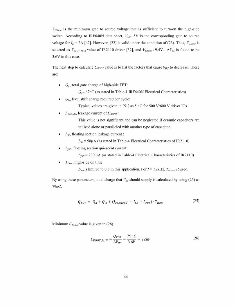
44
VGSmin is the minimum gate to source voltage that is sufficient to turn-on the high-side
switch. According to IRF640N data sheet, VGS = 5V is the corresponding gate to source
voltage for ID = 2A [47]. However, (22) is valid under the condition of (23). Thus, VGSmin is
selected as VBSUV-MAX value of IR2110 driver [32], and VGSmin = 9.4V. ∆VBS is found to be
3.6V in this case.
The next step to calculate CBOOT value is to list the factors that cause %dJ to decrease. These
are:
• Qg , total gate charge of high-side FET:
Qg = 67nC (as stated in Table-1 IRF640N Electrical Characteristics)
• Qls, level shift charge required per cycle:
Typical values are given in [51] as 5 nC for 500 V/600 V driver ICs
• Icbs(leak), leakage current of CBOOT :
This value is not significant and can be neglected if ceramic capacitors are
utilized alone or paralleled with another type of capacitor.
• ILK, floating section leakage current :
ILK = 50µA (as stated in Table-4 Electrical Characteristics of IR2110)
• IQBS, floating section quiescent current:
IQBS = 230 µA (as stated in Table-4 Electrical Characteristics of IR2110)
• THon , high-side on time:
Don is limited to 0.8 in this application. For f = 32kHz, THon = 25µsec.
By using these parameters, total charge that VBS should supply is calculated by using (25) as
79nC.
`MLM = `a + `b + -l-b"m0 + no + pdJ0 ∙ GK4E (25)
Minimum CBOOT value is given in (26).
qdLLM_st6 = `MLM∆%dJ
= 79=q3.6% = 22nF (26)

45
UF4007 is suitable for DBOOT with a fast recovery time (trr = 75ns). A blocking voltage
higher than VBUS is selected.
Another important issue about the H-bridge topology is adding a dead-time between high-
side and low-side switches to avoid short circuiting the bus voltage. IR2110 introduces an
approximately 25ns dead-time as a consequence of close mismatch of propagation delays
where worst case MT is stated as 10ns and turn-on propagation delay being 25ns longer
than turn-off propagation delay. To add a safety margin, a resistor-diode network is added
to the gate [51]. The effect of this network is further delaying the turn-on, without changing
the turn-off time.
4.4 Digital Control
4.4.1 Microcontroller
All the digital domain operations are accomplished on a microcontroller. These are
interpreting the input commands coming from the controller unit, storing the current
reference table, managing the current control calculations utilizing ADC channels or
alternatively, analog comparator outputs and generating the PWM signals accordingly.
PIC18F4431 [31] is selected for this task. PIC18F4431 is an 8-bit microcontroller that can
be operated at up-to 40MHz with external oscillator and is preferable due to its features that
are useful for motor control applications, such as advanced PWM, A/D modules and
encoder interface.
4.4.2 Scope and Specifications
The first task according to the operation sequence is interpreting the input commands.
These are step and the direction input. Step input comes in a pulse form, where negative
edge of the each active low pulse represents a command for a new step. Direction input is
in binary format, where one represents clockwise direction, and zero represents a counter-
clockwise direction. Waveform diagrams of these input signals are shown in Figure 29.

46
Figure 29 Timing diagram of input commands.
These two signals are generated in the controller unit and conditioned in an opto-coupler
circuitry which is shown in Figure 30. This circuit provides isolation between controller
unit and driver, and also filters input spikes with proper R_I7 and C_I7 values. t2 is
restricted by the input filter time constant which is given in (27) and is expected to be about
ten times of this value. t1 and t3 are restricted by the microcontroller speed.
, = +_ ∗ q_ (27)
Figure 30 Opto-coupler circuit for input command.
Step input is connected to one of the timer inputs of the microcontroller check at every
PWM period beginning along with the direction input.
A/D interface is capable of simultaneously processing two ADC inputs at a time and
sequential sampling is possible. A/D module is triggered by the power control PWM period
beginning. Acquisition time of the A/D module is programmable.
PWM outputs are generated by using the power control PWM module which simplifies
generation of the needed gate signals for half-bridge switches by utilizing the available
complementary mode and programmable dead-time generator.
PWM signals are controlled over a digital counter inside the microcontroller. PWM outputs
are generated by comparing this counter, ptmr, with the reference duty cycle value dPWM
3
4
2
1

47
according to the formula given in (28), where CS1 is the appropriate drive signal that
controls gate voltages of upper full-bridge transistors and CS2 is its inverse.
q:1 = 1, q:2 = 0 ; )Nxs ≥ *zq:1 = 0, q:2 = 1 ; )Nxs < *z (28)
The on time of S1, ton, can be expressed in terms of the newly introduced parameters in (29)
and [50] where pPWM is the PWM period value and the maximum of ptmr where ptmr drops
to zero when reached to pPWM. Duty ratio of S1 is also revealed with (30).
*4E = )NxsNxs
∙ G (29)
H1 = *4EG
= )NxsNxs
(30)
Thus D1 and D3, and therefore also D2 and D4 can easily be controlled by adjusting the
duty cycle and period values inside the microcontroller. This results in a complete control
of all available vo levels.
4.4.3 Algorithm
The microcontroller runs an interrupt driven software program where the most critical
operations are handled in an interrupt handler routine. The execution is switched to the
interrupt routine when ptmr resets to zero and a new PWM period begins. Figure 31 shows
the summary of the software code that generates the PWM signals for driving the step
motor.
The microcontroller performs initialization tasks on reset. Firstly, pin control registers are
set to enable correct communication between microcontroller and the peripherals.
Afterwards, several variables and flags are reset to their default values. This includes
setting the iteration index for current micro-step to the beginning of a look-up table that is
stored inside the electrically erasable programmable read-only memory (EEPROM) of the
microcontroller. This table stores PWM duty cycles for every possible micro-step and its
contents are calculated offline on a desktop computer.

Controller inputs, which are direction and step pulse, are connected to two different digital
input pins of the microcontroller. The direction input is continuous and thus it is polled
periodically. Step pulse input is a short logical pulse that is sent by the controller
a single micro-stepping rotation
is collected asynchronous from the instruction execution with the external counter
capabilities of microcontroller timer. A periodic check on this co
pulses even if they end before the check.
(a)
Figure 31 Flowcharts for (a) Main execution and (b) interrupt routine for microcontroller
software.
The PIC18F4431 features a power PWM module that
output complementary modes, programmable dead
override with logical levels. Eight PWM pins are connected to the eight gate driver inputs
to drive eight transistors contained in two full
pins are run in complementary mode where even numbered PWM pins output the inverse of
their odd numbered counterparts with possible dead
connected to high side transistors and low
inverse PWM signals. PWM module is also configured to raise interrupts when
changes to zero.
Initialize pins and variables
Initialize timer counter
Initialize PWM module
Enable interrupts
Debug Loop
48
ts, which are direction and step pulse, are connected to two different digital
input pins of the microcontroller. The direction input is continuous and thus it is polled
periodically. Step pulse input is a short logical pulse that is sent by the controller
stepping rotation in the direction dictated by the direction input. Pulse input
is collected asynchronous from the instruction execution with the external counter
capabilities of microcontroller timer. A periodic check on this counter ensures capture of
pulses even if they end before the check.
(b)
Flowcharts for (a) Main execution and (b) interrupt routine for microcontroller
The PIC18F4431 features a power PWM module that supports eight PWM outputs with
output complementary modes, programmable dead-time insertions and optional PWM
with logical levels. Eight PWM pins are connected to the eight gate driver inputs
to drive eight transistors contained in two full-bridge converters for two phases. The PWM
pins are run in complementary mode where even numbered PWM pins output the inverse of
their odd numbered counterparts with possible dead-time insertions. Odd numbered pins are
connected to high side transistors and low side transistor gates are always fed with the
inverse PWM signals. PWM module is also configured to raise interrupts when
Initialize pins and variables
Initialize timer counter
Initialize PWM module
Enable interrupts
Debug Loop
Read direction from
controller
Read step pulse from
If step pulse is given, iterate
on LUT
Read sin and cos table
Change PWM duty cycles interrupt flag
ts, which are direction and step pulse, are connected to two different digital
input pins of the microcontroller. The direction input is continuous and thus it is polled
periodically. Step pulse input is a short logical pulse that is sent by the controller to request
in the direction dictated by the direction input. Pulse input
is collected asynchronous from the instruction execution with the external counter
unter ensures capture of
Flowcharts for (a) Main execution and (b) interrupt routine for microcontroller
supports eight PWM outputs with
tions and optional PWM
with logical levels. Eight PWM pins are connected to the eight gate driver inputs
ge converters for two phases. The PWM
pins are run in complementary mode where even numbered PWM pins output the inverse of
time insertions. Odd numbered pins are
gates are always fed with the
inverse PWM signals. PWM module is also configured to raise interrupts when ptmr
Read step pulse from
timer
If step pulse is given, iterate
on LUT
Clear interrupt flag

49
Initialization on microcontroller reset ends with the enabling of system-wide interrupts.
This starts the periodic call of the interrupt handler when PWM periods begin. After
initialization, the main execution switches to a continuous debug loop where variables in
the code are sent to some digital output pins serially at low speeds. This is only used to
trace and confirm correct operation of the software during development stage.
The system automatically increments ptmr at every clock of the external oscillator
connected to the microcontroller. When ptmr exceeds pPWM, it is reset back to zero and an
interrupt flag is set to break main execution and switch instruction flow to an interrupt
handler at the first opportunity. The actual work of the microcontroller is done inside this
interrupt handler.
The interrupt handler routine starts with the polling of controller commands. Direction
input is read directly from the connected input port and the step pulse is read from an
externally incremented counter value. If this counter contains a value and clockwise
direction is requested, the iterator index on sinusoidal look-up table is incremented. If
counter-clockwise direction is requested this index is decremented.
The table index, whether it is modified or not, stores the duty cycle to use for the current
micro-step for the first phase. The duty cycle for the second phase can be found by fetching
from the table with an offset corresponding to 90º, e.g. an offset of 32 is used for a micro-
step resolution of 128. These duty cycles are written to duty cycle registers of the
microcontroller to take effect starting from the next PWM period. Delaying of duty cycle
change is possible with the double buffering features of power PWM module.
The interrupt routine ends by clearing the interrupt flag which caused the handler to
execute. This ensures the handling of further requests if necessary.
The software for the microcontroller is written in C and compiled to chip binary with HI-
TECH Picc18 compiler of Microchip Technology.
4.5 Current Control Feedback
Current reference table stored inside the EEPROM of the microcontroller keeps reference
current values for micro-stepping operation. A pulse counter is incremented for each step
input when direction is positive and decremented when direction is negative. This counter
is used as an index for the current reference table. So, referent current value is refreshed

50
based on this information. The output of the driver is forced to follow the reference current
by means of the power converter components described earlier.
There are two approaches to control current in step motor drives [27] in a loop. First
approach is to use an ADC to convert measured analog current to digital and compare this
current value with the referent current in digital domain. In second approach, referent
current is converted to analog by using a DAC and the comparison is done in analog
domain by means of a comparator.
The implemented driver supports both current control mechanisms and it can switch from
one to another with its microcontroller software. The ADC measurement approach is
supplemented with a PI control software block which performs tuning of duty cycle values
with respect to the PI output as described in Chapter 3. The DAC approach leads to a
simple P control where appropriate gate drivers are shutdown when the control error is
negative.

51
CHAPTER 5
5. EXPERIMETS
Conducted experiments to test the operational validity and performance of the designed
step motor driver are explained in this chapter. The chapter starts with an introduction of
the experimental setup in the first section. Then, tests relating to validation of the operation
of the motor driver are presented. Finally, test results of the implemented driver with a
CNC controller for its performance on accuracy and torque output are discussed.
5.1 Experimental Setup
The designed step motor driver is implemented on a four layer printed circuit board (PCB)
as seen in Figure 32. Also, an accompanying test setup composed of a controller with user
input panel and a power stage that provides 34V DC supply from 220V AC input has been
established for the tests of the step motor driver designed and implemented in this thesis.
User input contains power on/off switch and direction input switches, a POT as the
adjustable step input and a button to start and stop motion. The setup is shown in Figure 33.
Table 6 Step motors tested for driver operation.
Motor Type Specifications
57SH-46N2C 5 deg/rev, R=0.94Ω/phase 23LM C058-05H 1.8 deg/rev, 1.4A/phase, 3.5V/phase 103G770-3441 1.8deg/rev, 1.35A, 3.9V
Several two-phase bipolar hybrid step motors are used in the tests. The names of these
motors are given in Table 6 with their specifications.

52
Figure 32 Implemented step motor driver on PCB.
Figure 33 Experimental setup: step motor and load on the left, driver in the middle and the
power supply on the right. PC controller interface is seen in the front.

53
Figure 34 Laboratory test setup with controller PC on the left and two different controller
interfaces on the right. The CNC drilling machine to operate is shown on the upper right
corner.
Figure 35 Setup for positioning tests.

54
Also, a DC motor with a type number of MAXON 2332.968-201 is used as a load generator
for the test step motor. The DC motor shaft is matched to the shaft of the test motor with a
flexible belt and the DC motor is operated in generator mode with a potentiometer
connected across the wires of the DC motor to adjust the load of the test motor.
5.2 Waveform Measurements
Step motor driver is tested under different speed, current set-point conditions and micro-
step resolutions. A Tektronix TDS5104 digital oscilloscope with two TCPA300 current
probes is used for the measurements. The results are shown in Figure 36, Figure 37 and
Figure 38.
Figure 36 (a) shows the clockwise and Figure 36 (b) shows the counter-clockwise operation
when the desired current set-point is 500mA peak, micro-step resolution is 128 and shaft
speed is 20rpm. The measurements are taken under no load condition.
Figure 36 (c) shows the current waveforms when a fixed load is connected to this
configuration. Here, motor is still capable of positioning without error, but there is a slight
distortion on the shape of current waveforms.
Figure 37 (a) shows the phase current waveforms when the desired current set-point is
800mA peak, micro-step resolution is 64 and shaft speed is 40rpm at no load. Since micro-
stepping resolution is halved, rotor displacement corresponding to one step command is
doubled. As a result, the speed of the rotor shaft is doubled with the same controller output
pulse settings. The shapes of the current waveforms are smoother as a result of increased
set current value. Figure 37 (b) shows the waveforms for the same configuration under a
fixed load. On the other hand, Figure 37 (c) still provides the no load waveforms, but this
time, step input rate from controller panel is increased. It can be observed that the peak
current value that the phase currents can reach is lower due to the increased back-EMF
voltage as the rotor speed increases from 40rpm to 54rpm.
Finally, Figure 38 (a) and (b) presents the current waveforms under no load and fixed load
conditions when micro-step resolution is reduced to 8. In no load condition, test motor is
able to start and stop properly. However, it loses steps with the same conditions under load.
This is expected as the current waveform in this case varies radically from the wave drive
pattern given in Figure 19 (b).

55
Current set-point 500mA
Micro-stepping resolution 128
Shaft speed 20rpm
Direction CW
Load None
(a)
Current set-point 500mA
Micro-stepping resolution 128
Shaft speed 20rpm
Direction CCW
Load None
(b)
Current set-point 500mA
Micro-stepping resolution 128
Shaft speed 20rpm
Direction CCW
Load Fixed
(c)
Figure 36 Phase current waveforms for 128 micro-step resolution. Blue is phase-A and red
is phase-B. (a) Clockwise rotation under no load, (b) counter-clockwise rotation under no
load and (c) counter-clockwise rotation under fixed load.

56
Current set-point 800mA
Micro-stepping resolution 64
Shaft speed 40rpm
Direction CW
Load None
(a)
Current set-point 800mA
Micro-stepping resolution 64
Shaft speed 40rpm
Direction CW
Load Fixed
(b)
Current set-point 800mA
Micro-stepping resolution 64
Shaft speed 54rpm
Direction CCW
Load Fixed
(c)
Figure 37 Phase current waveforms for 64 micro-step resolution. Blue is phase-A and red is
phase-B. (a) 40rpm speed under no load, (b) 40rpm speed under fixed load and (c) 54rpm
speed under load.

57
Current set-point 800mA
Micro-stepping resolution 8
Shaft speed 320rpm
Direction CCW
Load None
(a)
Current set-point 800mA
Micro-stepping resolution 8
Shaft speed 320rpm
Direction CCW
Load Fixed
(b)
Figure 38 Phase current waveforms for 8 micro-step resolution. Blue is phase-A and red is
phase-B. (a) 320rpm rotation under no load and (b) 320 rpm rotation under fixed load.

58
5.3 C1C Operation
Step motors are widely used in computer numerical control (CNC) applications. Proposed
step motor driver is also aimed to be suitable for a CNC application and the driver is tested
with a CNC machine.
The CNC machine used in the tests is a desktop CNC machine with a type number of
HC501. Besides its drilling head mechanism, it is composed of several components. There
are three step motors from Sanyo Denki Inc. with per phase specifications of 5V - 1.4A and
a holding torque of 50 oz-inch for the X, Y and Z axes. Each motor is driven by a separate
step motor driver with the code name M2MD504. There is a power converter module for all
of the electronic equipment on the machine and also a controller unit which provides the
control signals for each of the three step motor drivers. The controller provides the control
signals by converting the input signals generated by utilizing a CAD program Matkap-pro
v4.3 on a PC, and carried to the controller via parallel port. The connections are shown in
Figure 34.
To test the step motor driver, a sample 2 dimensional model is selected where Y axis is
commanded to follow a line and come back to the original position. Step motor driver unit
under test is connected to the Y axis controller output and an indicator is put to the shaft of
the test motor to observe if the step motor comes to its first rest position after operation of
the program. Length of the path is calibrated to a value under no load and low speed to a
value where the step motor under test performs a single revolution or its integral multiples.
CNC operation tests start with validating correct operation of the controller interface of the
designed step motor driver by using the controller unit of the CNC machine. It is a
necessity for the implemented driver to advance a single micro-step for each step pulse sent
from the controller and to respond immediately after a change in direction input occurs.
These requirements are confirmed by giving the same amount of step commands in the
positive direction from a known rotor position and afterwards in the opposite direction. The
controller-driver interface will be validated when it is observed that the rotor returns back
to the initial position. An indicator,which is put on the rotating shaft as seen in Figure 35, is
used to observe if the rotor returns to the initial position. The motor is rotated for multiples
of one full revolution and observed whether a cumulative position error occurs or not. The
test is done in a low speed light load condition to avoid any error that may occur if the
system falls in the region under the pull out torque characteristic curve.

59
Table 7 Results for positional accuracy tests with a CNC controller.
Micro-step
Resolution
Current
Set-point
7umber of micro-step commands
required for one full revolution Passed/Failed
128 1.6A(p-p) 6400 Passed
64 1.6A(p-p) 3200 Passed
32 1.6A(p-p) 1600 Passed
16 1.6A(p-p) 800 Passed
8 1.6A(p-p) 400 Passed
The accuracy of different micro-stepping resolutions is tested with the test setup described.
The results are summarized in Table 7. Number of step commands needed for one full
revolution are calculated with (31) where ps is the number of full steps per revolution and µs
is the number of micro-steps per one natural step.
= 1 ∗ (31)
Number of micro-steps per full step, µs, is calculated as one fourth of the micro-step
resolution. Because, spanning all distinct micro-steps for a complete sinusoidal wave
iterates over four natural steps as shown in Figure 19. Thus, for a micro-step resolution of
128, µs is 32. In this test, ps = 200 as the test motor is a 1.8°/rev step motor.
This test is conducted with different motors and micro-stepping with different resolutions is
achieved with a 1.8°/rev mini-angle step motor from Astrosyn Inc. having a type number of
23LM-C058-05H. The second motor used is another 1.8°/rev step motor from Sanyo Denki
Inc. having a type number of 103G770-3441. Micro-stepping is also achieved with this
motor. However, tests with a 5°/rev step motor having a type number of 57SH-4672C,
which is the step motor used from DPM Inc., was not able to return to the initial position
after the micro-step commands required for one full revolution was sent from the controller,
i.e., the test motor has failed to achieve micro-stepping in the desired resolutions this time.
This result indicates that motor selection is an important issue to ensure proper micro-
stepping operation. There are some common concerns that may limit accurate positioning in

60
a micro-stepping realization. If the motor is optimized for full-stepping, micro-stepping
operation accuracy is reduced as in this case [37].
The next step is to constitute the load-speed diagrams of the driver system. A DC motor
load with a type number of MAXO7 2332.968-201 is connected to the shaft of the test
motor using a flexible band to ensure a smooth start for the step motor. Load motor is
operated in generator mode. A variable resistor is connected across the windings of the
motor to provide an adjustable load. The step motor driver is operated for different micro-
stepping resolutions. The load capacity is observed by changing speed and load torque
conditions. Load torque is approximately calculated by using the formula in (32).
Gb4X = %4l ∙ b4X4/4
(32)
In (32), %4l is the open circuit average voltage seen across the winding terminals of the load
motor corresponding to the angular velocity of test motor rotor shaft or wrotor. Iload is the
value of the current that flows through the adjustable load. Immeasurable loads such as
friction effects, additional inertia of the shaft or power loss on the motors are neglected in
this calculation.
The test motor is operated under various speed and load conditions, where potentiometer is
adjusted to six different resistance settings and the motor speed is increased until the test
motor starts to lose step. The test is repeated for two different micro-step resolutions. These
measurements for micro-step resolution 32 and 8 are given in Table 8 and Table 9.
Table 8 Test results for the maximum load torques achieved before the test motor starts to
lose steps for micro-step resolution γ=32.
Iload
(mA)
Voc
(V)
t
(s/rev)
f
(rev/s)
wrotor
(rad/s)
Tload
(m7·m)
44 3.00 0.962 1.039 6.531 20.211 50 3.00 1.008 0.992 6.234 24.061 60 3.00 1.054 0.949 5.963 30.185 80 2.80 1.191 0.840 5.275 42.464
110 2.30 1.374 0.728 4.572 55.340 120 2.10 1.532 0.652 4.100 61.464

61
Table 9 Test results for the maximum load torques achieved before the test motor starts to
lose steps for micro-step resolution γ=8.
Iload
(mA)
Voc
(V)
t
(s/rev)
f
(rev/s)
wrotor
(rad/s)
Tload
(m7·m)
38 2.80 1.198 0.835 5.244 20.290 43 2.80 1.198 0.835 5.244 22.960 54 2.60 1.273 0.785 4.935 28.447 69 2.40 1.348 0.742 4.661 35.527 99 2.10 1.572 0.636 3.995 52.035
100 1.90 2.210 0.452 2.843 66.830
The maximum load torque values which do not lead to any displacement error in the rotor
shaft for 1/8th micro-stepping condition (γ=8) and 1/32nd micro-stepping condition (γ=32),
that are shown in Table 8 and Table 9 are displayed together in Figure 39. The results have
their own limitations as the current set point is below the rated value of the motor.
However, the Figure 39 underlines the fact that the performance of the driver is clearly
improved by increasing the micro-step resolution where all other conditions remain same as
it is expected. The torque output of the motor is expected to be more stable. These results
are important in this sense.
Figure 39 Load – speed curves for two different micro-stepping resolutions.
0
0.01
0.02
0.03
0.04
0.05
0.06
0.07
0.08
0 1 2 3 4 5 6 7
Tor
qu
e (
·m)
Angular velocity (rad/s)
γ=8
γ=32

62
CHAPTER 6
6. COCLUSIOS
This chapter begins with a summary of the work presented in this thesis. Second section
provides remarks on the experimental results obtained. The third and the final section
provide a discussion of possible improvements to the methods presented.
6.1 Summary
Step motors provide fine control of rotation angle and speed through discrete excitation
signals. Micro-stepping enables higher precision through fractional excitation of step motor
windings.
Microcontrollers enable efficient and simple generation of discrete digital signals. Low cost
and effective electronic utilities are realized with the use of microcontrollers and
accompanying circuitry in conjunction.
There are different driver topologies for step motor control, each having advantages and
disadvantages for certain needs. Micro-stepping can be enabled using the H-bridge
topology.
This thesis puts forward a step motor driver system that performs bipolar drive of 2-phase
hybrid step motors. PIC18F4431, which is an 8-bit microcontroller in motor control family
of Microchip Inc., forms the core of the realization of the driver presented in this thesis
work. The microcontroller manages the controller – driver interface, executes the
operations required for realization of micro-stepping and also provides PWM outputs of the
power converter section of the driver properly. The power converter section is constructed

63
by utilizing the full-bridge topology with discrete circuit elements. Constructed full bridge
circuits provide a flexible environment to improve output power capability and enable
driver algorithm selection in contrast to IC alternatives.
6.2 Discussions
A step motor driver with micro-stepping capability is designed and realized on a PCB in
this thesis. The micro-stepping property is tested and functional operation is validated
through tests. The driver is realized and tested for Vbus = 34Vdc and 1.6A (p-p) currents per
phase. The driver works successfully by using the fixed current control method introduced
in Chapter 3.
For an improved torque capability, two current feedback loop alternatives are constructed
and the loop components are validated through functional tests. However, there are some
problems encountered related to current measurements from sensing resistors which are
discussed in detail in section 4.2.3. To summarize, voltage and current waveforms on the
sensing resistors are in a pulsed form. This brings a challenge to the evaluation process of
the sensing current. Especially considering the cases where a high bus voltage is used in
order to manipulate the current quickly, on-time of duty cycle becomes small. Also, rapid
voltage and current changes occur due to the nature of the chopper configuration. Thus,
there is a potential risk of observing unwanted signals on the sensing resistors occurring
right after the start of the on-time originated from ground bounce issues. To overcome this
problem, PIC18F4431 ADC captures input data each time a special event trigger occurs.
Samples can be taken from unambiguous points on the waveform by this way. There is also
a programmed delay element to adjust the exact sample points. This feature is also used to
ensure that analog input is captured after the waveform settles and the effect of ground
bounce is ended. However, sampling the voltage values that are the exact representations of
the phase currents is impossible because the effects of these ripples are dominating. Since
further solutions to this problem require design and implementation of a new PCB from
scratch, this issue is left as a future work.
Tests reveal that increased current set-point and increased micro-stepping resolution results
in higher torque output and more stable operation. Higher torque output leads to clean
waveforms for phase current and thus less audible noise and less chance of missing steps.
Current sensing feedback will enable efficient operation for a wider range of load and speed
configurations.

64
6.3 Future Work
Step motors can operate with a fairly well performance without a position control feedback
mechanism. In case of some unexpected operating conditions, a position feedback control
mechanism can be helpful to detect a fault condition. Thus, adding a position sensor and a
closed-loop position feedback system is expected to provide an improvement to the step
motor driver.
The user interface of the step motor driver can be improved. For example, a software tool
can be added to the system that allows user to simply choose the system parameters and
operation modes of the driver by means of a GUI as in some industrial examples of step
motor drivers.
It is also possible to enhance the driver design by adding some protection functions such as
output short circuit protection or over temperature protection.

65
REFERECES
[1] A. G. Thomas and F. J. Fleischauer, "The power stepping motor- a new digital
actuator," Control engineering 4, pp. 74-81, January 1957.
[2] T. Roland Frederiksen, "Applications of the closed-loop stepping motor," IEEE
Transactions on Automatic Control, vol. 13, no. 5, pp. 464-474, October 1968.
[3] E. K. Pritchard, "Ministepping step motor drives," in Proc. 5th Annual Sympmosium of
Incremental Motion Control Systems Devices, 1976.
[4] Kenjo Takashi, Stepping motors and their microprocessor controls. Kanagawa, Japan:
Clarendon Press, 1984.
[5] Muhammed F. Rahman and Aun-Neow Poo, "An application oriented test procedure
for designing microstepping step motor controllers," IEEE Transactions on Industrial
Electronics, vol. 35, no. 4, pp. 542-546, November 1988.
[6] T.C. Chin, D.P. Mital, and M.A. Jabbar, "A stepper motor controller," in Proceedings
of the International Conference on Control, Oxford, UK, 1988, pp. 500-505.
[7] R.H. Brown and K. Srinivas, "A damping circuit for chopper driven bifilar hybrid
stepper motors," in Proceedings of the Power Electronics Specialists Conference,
Milwaukee, WI , USA, 1989, pp. 446-451.
[8] A. Imagi, M. Tomisawa, and T. Koizumi, "State and parameter estimation for step
motors under actual working conditions," in Conference Proceedings of the 16th
Annual Conference on Industrial Electronics Society, Pacific Grove, CA, USA, 1990,
pp. 114-119.
[9] A.J. Blauch, M. Bodson, and J. Chiasson, "High-speed parameter estimation of stepper
motors," IEEE Transactions on Control Systems Technology, vol. 1, no. 4, pp. 270-
279, December 1993.
66
[10] J. Chen, D. Gaeiro, and E Stoeckert, "Spice modeling of a stepper motor with its
control, drive and load," in Proceedings of the Industry Applications Society Annual
Meeting, Seattle, WA , USA, 1990, pp. 190-195.
[11] G. Baluta, "Microstepping mode for stepper motor control," in International
Symposium on Signals, Circuits and Systems , Iasi, Romania, 2007.
[12] Sheng-Ming Yang, Feng-Chieh Lin, and Ming-Tsung Chen, "Micro-Stepping Control
of a Two-Phase Linear Stepping Motor With Three-Phase VSI Inverter for High-Speed
Applications," IEEE transactions on industrial applications, vol. 40, no. 5, September
2004.
[13] A. Astarloa, U. Bidarte, A. Zuloaga, and I.M. de Alegria, "Reconfigurable
microstepping control of stepper motors using fpga embedded ram," in Proceedings of
the 29th Annual Conference of the IEEE of the Industrial Electronics Society,
Roanoke, VA, USA, 2003, pp. 2221-2226.
[14] W. McClelland, "The application of the electricity in warships," Journal of the
Instutition of Electrical Engineers, vol. 65, no. 369, pp. 866 - 869, September 1927.
[15] C. L. Walker, "Improvements in and connected with electromagnetic step by step
signaling and syncronous rotation," 137,150, 1919.
[16] C. B. and Thain, J. H. Chicken, "Electrical Signaling Apparatus," 1,353,025, 1920.
[17] K. M. Feiertag and J.T. Donahoo, "Dynamoelectric machine," 2589999, 1952.
[18] V. Marano and D. Arrigo, "Novel fully-integrated 65W stepper motor driver IC," in
International Symposium on Power Electronics, Electrical Drives, Automation and
Motion, 2006.
[19] Pu Ji, Xiuhe Wang, Feng Lin, Rong Zhang, and Shiyong Liu, "Application of
LMD18245 in two phase hybrid stepping motor driver," in Proceedings of the Eighth
International Conference on Electrical Machines and Systems, Nanjing, China, 2005,
pp. 706-709.
[20] National Semiconductor, "LMD18245 3A, 55V DMOS Full-Bridge Motor Driver ,"

67
Data Sheet 2006.
[21] Allegro, "A3981, Automotive, Programmable Stepper Driver," Data Sheet 2010.
[22] Allegro, "A4980, Automotive, Programmable Stepper Driver," Data Sheet 2010.
[23] ON Semiconductor, "AMIS-30523 CAN micro-stepping motor driver," Data Sheet.
[24] Peter Cox and Guido Remmerie, "Driver ICs elevate design of stepper-motor control,"
Power Electronics Technology, August 2007.
[25] Mongkol Konghirun and Chawakorn Yodsanti, "Microstepping Bipolar Drive of Two-
Phase Hybrid Stepping Motor on TMS320F2808 DSC," King Mongkut's University of
Technology, Thonburi, Application Report 2008.
[26] A. Bellini, C. Concari, G. Franceschini, and A. Toscani, "Mixed-mode pwm for high-
performance stepping motors," IEEE Transactions on Industrial Electronics, vol. 54,
no. 6, pp. 3167-3177, December 2007.
[27] Ngoc Quy Le and Jae Wook Jeon, "An open-loop stepper motor driver based on fpga,"
in Proccedings of the International Conference on Control, Automation and Systems,
Seoul, Korea, 2007, pp. 1322-1326.
[28] Xiaodong Zhang, Junjun He, and Chunlei Sheng, "An approach of micro-stepping
control for the step motors based on fpga," in Proceedings of the IEEE International
Conference on Industrial Technology, Hong Kong, PRC, 2005, pp. 125-130.
[29] Sorin Manea, "Stepper Motor Control with dsPIC® DSCs," Microchip Technology
Inc., Application Note 2009.
[30] Ran Zhang, Xiuhe Wang, Yubo Yang, and Dongwei Qiao, "Design of two-phase
hybrid stepping motor driver with current closed-loop control based on PIC18F2331,"
in Proceedings of the International Conference on Electrical Machines and Systems,
Wuhan, PRC, 2009, pp. 2998-3001.
[31] Microchip Technology Inc, "PIC18F2331/2431/4331/4431 Data Sheet," 2003.

68
[32] International Rectifier, "IR2110 High and low side driver," Data Sheet 2005.
[33] T.S. Weerakoon and L. Samaranayake, "Development of a Novel Drive Topology for
a Five Phase Stepper Motor," in IEEE Region 10 Colloquium and the Third ICIIS,
2008.
[34] Alexandru Morar, "Stepper motor model for dynamic simulation," Achta Electronica,
vol. 44, no. 2, pp. 117-122, 2003.
[35] M. Zribi and J. Chiasson, "Position Control of a PM Stepper Motor by Exact
Linearization," IEEE transactions on automatic control, vol. 36, no. 5, pp. 620-625,
May 1991.
[36] David J. Griffiths, "Maxwell's stress tensor," in Introduction to Electrodynamics.:
Benjamin Cummings Inc., 2008, pp. 351 - 352.
[37] Ericsson. Industrial Circuits Application Note: Stepper Motor Basics. [Online].
http://www.solarbotics.net/library.html
[38] G. Baluta and M. Coteata, "Precision microstepping system for bipolar stepper motor
control," in Conference Proceedings of the International Aegean Conference on
Electrical Machines and Power Electronics, Muğla, Turkey, 2007, pp. 291-296.
[39] Acarnley, Stepping Motors: a guide to modern theory and practice, 3rd ed. England:
Peter Peregrinus Ltd, 1992.
[40] Douglas W. Jones, "Current limiting for stepping motors," in Handbook of small
electric motors, Alan W. Yeadon William H. Yeadon, Ed.: McGraw-Hill, 2001, ch. 10.
[41] ST Microeelectronics, "Microstepping Stepper Motor Drive Using Peak Detecting
Current Control," Application Note 2004.
[42] K. L. Sh and Hui Li, "Optimized PWM strategy based on genetic algorithms," IEEE
Transactions on industrial electronics, vol. 52, no. 5, pp. 1458-1561, October 2005.
[43] L. Peng, Y. Kang, X. Pei, and J. Chen, "A novel pwm technique in digital control,"
IEEE Transactions on Industrial Electronics, vol. 54, no. 1, pp. 338-346, February

69
2007.
[44] Carl Blake and Chris Bull, "IGBT or MOSFET: Choose Wisely," International
Rectifier, Application Note 2006.
[45] Maxim Integrated Products, "Power supply engineer's guide to calculate dissipation for
MOSFETs in high-power supplies ," Application Note 2002.
[46] (2005) H-bridge secrets. [Online]. http://www.modularcircuits.com/h-
bridge_secrets1.htm
[47] International Rectifier, "IRF640N," Data Sheet 2004.
[48] ON Semiconductor, "MUR420 Switchmode power rectifiers," Data Sheet 2010.
[49] Ansoft, Ansoft-Simplorer V7.0. A power electronics simulation software, 2004.
[50] Ned Mohan, Tore M. Undeland, and William P. Robbins, Power Electronics
Converters, Applications, and Design, 3rd ed.: John Wiley and Sons, Inc., 2003.
[51] International Rectifier, "HV floating MOS-gate driver ICs," Application Note 2007.
[52] A. Merello, A. Rugginenti, and M. Grasso, "Using monolithic high voltage gate
drivers," International Rectifier, Design tips.
[53] Fairchild Semiconductor, "UF4001-UF4007 Fast Rectifiers," Data Sheet 2005.