Embed Size (px)
Citation preview

DESIGN AND PERFORMANCE OF THE OPTICAL FIBER LENGTH STABILIZATION SYSTEM FOR SACLA
H. Maesaka#, T. Ohshima, Y. Otake, RIKEN SPring-8 Center, Kouto, Sayo, Hyogo, 679-5148, Japan S. Matsubara, JASRI XFEL Utilization Division, Kouto, Sayo, Hyogo, 679-5198, Japan
Abstract In order to synchronize precisely between accelerator
components in the x-ray free-electron laser facility, SACLA, an optical fiber length stabilization system for a reference rf signal transmitter was developed and installed. A tolerance of timing drift is set to be 50 fs. In order to achieve this stability, we employed an optical interferometer to measure the optical path-length variation. A frequency-stabilized laser with a wavelength of 1.5 μm is transmitted to a receiver together with an rf signal and it is reflected back to the interferometer. The fiber length drift is compensated with a piezo-electric fiber stretcher according to the optical length variation detected by the interferometer. By using this system, the timing drift of a reference rf signal transferred through a several-100m-long optical fiber was confirmed to be suppressed within 50 fs. Consequently, the optical fiber length stabilization system has sufficient accuracy for SACLA.
INTRODUCTION The accelerator components of the x-ray free electron
laser (XFEL) facility, SACLA, must be precisely synchronized with a master clock for stable generation of x-ray laser pulses. For some user experiments, such as a pump-and-probe experiment, synchronization between the accelerator and experimental apparatus is also needed. The timing stability of such synchronization is required to be 50 fs for SACLA [1] throughout the 700m-long facility. In order to achieve this timing stability, we developed a stable optical rf distribution system [2] by using optical communication technologies around the wavelength of 1550 nm.
In the optical rf distribution system, following techniques are employed in order to reduce timing drift. 1. A phase-stabilized optical fiber having a temperature
coefficient of 5 ps/km/K is used for optical signal transmission.
2. Optical fiber cables are inserted into a temperature-regulated duct with a temperature stability of 0.4 K peak-to-peak.
3. All the electronics are enclosed in water-cooled 19-inch racks with a temperature stability of 0.4 K peak-to-peak.
Even in this case, a timing drift of more than 1 ps can be anticipated for a 1km-long optical fiber. In fact, a timing drift of more than 100 fs has been observed by many instruments in SACLA [3]. Since one of the reasons of this timing drift can be optical fiber length variation, we
developed an optical fiber length stabilization system and installed into SACLA.
In this article, we describe the design and performance of the fiber length stabilization system for SACLA. Some of the performance data taken during actual accelerator operation are also reported.
SYSTEM OVERVIEW A schematic diagram of the optical fiber length
stabilization system is shown in Fig. 1 together with the optical rf distribution system. There are two optical fibers connected to a destination. One is for the optical fiber length stabilization system (OptRef) and the other is for transmission of rf signals used by accelerator components (RfRef). Since the optical fiber for OptRef is separated with that of RfRef, a flexible design for the OptRef system can be enabled and a failure in the OptRef system does not affect the RfRef system. By using the two fiber links, moreover, we can compensate the length variation of not only the transmission fiber, but also optical components in the RfRef system, such as an erbium-doped fiber amplifier (EDFA).
In an OptRef fiber, frequency-stabilized laser light is transmitted to a receiver as a length standard. This laser light is reflected back to a transmitter side. The optical path length variation is detected by an interferometer and fed back to a piezo-electric fiber stretcher in order to compensate the length variation. In addition, an optical 5712 MHz rf signal is transmitted together in this OptRef fiber. This rf signal is utilized for the phase reference of the rf signal transferred by the RfRef system.
For the RfRef system, rf signals of 5712 MHz and its sub-harmonics are generated by a master oscillator and converted to optical signals with electric-to-optical (E/O) converters. These signals are combined into one optical fiber by using the wavelength-division multiplexing (WDM) technology. These optical signals are amplified by an EDFA and distributed to accelerator components. Each optical signal is converted back to the electric rf signal with an optical-to-electric (O/E) converter in a receiver and used for an accelerator unit, beam diagnostics etc. One of the 5712 MHz signals is sent to a phase detector and the optical length drift is monitored as a phase difference with the 5712 MHz signal from the OptRef system. The detected phase is utilized for driving a piezo-electric fiber stretcher for the RfRef system inserted before the receiver and the optical length drift is compensated with the stretcher.
___________________________________________
5th International Particle Accelerator Conference IPAC2014, Dresden, Germany JACoW PublishingISBN: 978-3-95450-132-8 doi:10.18429/JACoW-IPAC2014-WEOBB01
WEOBB011906
Cont
entf
rom
this
wor
km
aybe
used
unde
rthe
term
soft
heCC
BY3.
0lic
ence
(©20
14).
Any
distr
ibut
ion
ofth
isw
ork
mus
tmai
ntai
nat
tribu
tion
toth
eau
thor
(s),
title
ofth
ew
ork,
publ
isher
,and
DO
I.
06 Instrumentation, Controls, Feedback & Operational AspectsT24 Timing and Synchronization

SETUP OF OPTICAL FIBER LENGTH STABILIZATION SYSTEM
A block diagram of the OptRef system is illustrated in Fig. 2. We use two length standards for optical fiber length measurements. One is a frequency-stabilized laser and the optical path length is detected as the phase of an optical frequency (f0 ~193 THz). The dynamic range of the length measurement is 1.5 μm, corresponding to 5 fs. The other is a pair of optical signals, f+ and f-, where the frequency difference between them is 91.4 GHz (millimeter wave). The path length is measured by detecting a phase of this millimeter-wave signal. The measurement dynamic range by using this signal is 11 ps.
Since there are two length standards, two feedback control loops for the length stabilization are constructed. In order to distinguish these two loops, we call the feedback loop of the frequency-stabilized laser “fine loop”, and that of the millimeter wave “coarse loop”. One of the advantages of this dual loop configuration is that we can cross-check control accuracy by comparing the detected lengths between the two loops. Moreover, since the dynamic range of the coarse loop is sufficiently large, the absolute length of the optical fiber can be restored even after the power off of the system. Thus, when the system is tuned on, the coarse loop recalls the absolute length and then the fine loop is activated for precise control.
In the interferometer, the optical signal passes through a polarization beam splitter (PBS) and fiber stretchers. The optical signal is reflected by a Faraday rotating
mirror (FRM) at the destination and an optical signal having an orthogonal polarization with respect to the forward light is returned. By using the FRM, only the returned light from the FRM can be obtained by the PBS and the other scattered light from a connector, an optical coupler, etc. is eliminated.
A portion of the optical signal is extracted for the reference light of the interferometer and the frequency of the reference light is shifted by a 238 MHz signal with an acousto-optic modulator (AOM). The reference light and the returned one are mixed by an optical coupler. The optical signal for each length standard is separated by a band-pass filter and detected with a photo-diode (PD). Since the frequency of the reference light is 238 MHz different from the returned light, a 238 MHz beat signal is obtained from the PD as an interferometry signal. The optical phase of the fine loop is reproduced as the phase difference of the beat signal with respect to the AOM input signal. The phase of the millimeter-wave signal in the coarse loop is detected by comparing the phases of the PD signals from the two optical signals, f+ and f-. The phase of the 238 MHz beat signal is detected by a phase-frequency discriminator (PFD). The detected phase is processed by a loop filter and fed into the fiber stretcher in order to regulate the optical fiber length.
As described in the previous section, the optical 5712 MHz rf signal is also generated in the OptRef system as the phase reference for the RfRef system. This optical rf signal is combined to the main optical fiber just after the PBS and detected with an O/E converter at the receiver side.
Figure 1: Schematic diagram of the optical rf distribution (RfRef) system in SACLA, including the optical fiber length stabilization (OptRef) system.
Figure 2: Block diagram of the optical fiber length stabilization (OptRef) system.
5th International Particle Accelerator Conference IPAC2014, Dresden, Germany JACoW PublishingISBN: 978-3-95450-132-8 doi:10.18429/JACoW-IPAC2014-WEOBB01
06 Instrumentation, Controls, Feedback & Operational AspectsT24 Timing and Synchronization
WEOBB011907
Cont
entf
rom
this
wor
km
aybe
used
unde
rthe
term
soft
heCC
BY3.
0lic
ence
(©20
14).
Any
distr
ibut
ion
ofth
isw
ork
mus
tmai
ntai
nat
tribu
tion
toth
eau
thor
(s),
title
ofth
ew
ork,
publ
isher
,and
DO
I.
The wavelength of the frequency-stabilized laser for the fine loop is locked to 1548.955 nm by using the P9 absorption line of H13C14N (hydrogen cyanide). The frequency stability of the stabilized laser is better than 1x10⁻⁹, corresponding to 1 μm accuracy for 1km-long distance measurement.
The optical signal for the coarse loop is generated by an external cavity laser diode (ECLD) followed by a LiNbO3 modulator (LN-MOD) driven by a 45.7 GHz signal (8 x 5712 MHz). The LN-MOD produces two sidebands (f+ and f-) around an input light frequency and the frequency difference of these sidebands is 91.4 GHz (= f+ – f-). A band-reject filter after the LN-MOD removes the input light and only the two sidebands, f+ and f-, are utilized for the length measurement. This light source is carefully designed to create a stable frequency interval of 91.4 GHz with almost the same stability as the 5712 MHz signal, which is better than 1x10⁻⁹. Therefore, the length measurement stability is almost same as the fine loop.
A piezo-electric fiber stretcher is used as a phase shifter of this system and it has a dynamic range of 3 mm. An optical fiber is coiled around a piezo-electric actuator and the actuator controls the path length by expanding the fiber. The frequency response of this fiber stretcher is flat up to 3 kHz and it has a mechanical resonance at 15 kHz.
For the feedback loop response, the corner frequencies of the fine and coarse loops are set to 1 kHz and 0.01 Hz, respectively. Since the fine loop is sensitive to nano-meter level perturbation, the bandwidth of the fine loop is designed to be wide for robust control under high frequency vibration. On the other hand, the bandwidth of the coarse loop is narrow, because of the low sensitivity to the small perturbation and the wide dynamic range of length measurement.
PERFORMANCE DATA The optical fiber length stabilization system is installed
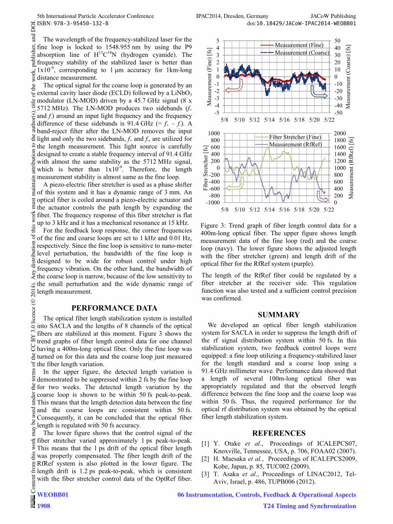
into SACLA and the lengths of 8 channels of the optical fibers are stabilized at this moment. Figure 3 shows the trend graphs of fiber length control data for one channel having a 400m-long optical fiber. Only the fine loop was turned on for this data and the coarse loop just measured the fiber length variation.
In the upper figure, the detected length variation is demonstrated to be suppressed within 2 fs by the fine loop for two weeks. The detected length variation by the coarse loop is shown to be within 50 fs peak-to-peak. This means that the length detection data between the fine and the coarse loops are consistent within 50 fs. Consequently, it can be concluded that the optical fiber length is regulated with 50 fs accuracy.
The lower figure shows that the control signal of the fiber stretcher varied approximately 1 ps peak-to-peak. This means that the 1 ps drift of the optical fiber length was properly compensated. The fiber length drift of the RfRef system is also plotted in the lower figure. The length drift is 1.2 ps peak-to-peak, which is consistent with the fiber stretcher control data of the OptRef fiber.
The length of the RfRef fiber could be regulated by a fiber stretcher at the receiver side. This regulation function was also tested and a sufficient control precision was confirmed.
SUMMARY We developed an optical fiber length stabilization
system for SACLA in order to suppress the length drift of the rf signal distribution system within 50 fs. In this stabilization system, two feedback control loops were equipped: a fine loop utilizing a frequency-stabilized laser for the length standard and a coarse loop using a 91.4 GHz millimeter wave. Performance data showed that a length of several 100m-long optical fiber was appropriately regulated and that the observed length difference between the fine loop and the coarse loop was within 50 fs. Thus, the required performance for the optical rf distribution system was obtained by the optical fiber length stabilization system.
REFERENCES [1] Y. Otake et al., Proceedings of ICALEPCS07,
Knoxville, Tennessee, USA, p. 706, FOAA02 (2007). [2] H. Maesaka et al., Proceedings of ICALEPCS2009,
Kobe, Japan, p. 85, TUC002 (2009). [3] T. Asaka et al., Proceedings of LINAC2012, Tel-
Aviv, Israel, p. 486, TUPB006 (2012).
Figure 3: Trend graph of fiber length control data for a 400m-long optical fiber. The upper figure shows length measurement data of the fine loop (red) and the coarse loop (navy). The lower figure shows the adjusted length with the fiber stretcher (green) and length drift of the optical fiber for the RfRef system (purple).
-50-40-30-20-1001020304050
-5-4-3-2-1012345
5/8 5/10 5/12 5/14 5/16 5/18 5/20 5/22
Mea
sure
men
t (C
oars
e) [
fs]
Mea
sure
men
t (Fi
ne)
[fs]
Measurement (Fine)Measurement (Coarse)
0200400600800100012001400160018002000
-1000-800-600-400-200
0200400600800
1000
5/8 5/10 5/12 5/14 5/16 5/18 5/20 5/22
Mea
sure
men
t (R
fRef
) [f
s]
Fib
er S
tret
cher
[fs
]
Fiber Stretcher (Fine)Measurement (RfRef)
5th International Particle Accelerator Conference IPAC2014, Dresden, Germany JACoW PublishingISBN: 978-3-95450-132-8 doi:10.18429/JACoW-IPAC2014-WEOBB01
WEOBB011908
Cont
entf
rom
this
wor
km
aybe
used
unde
rthe
term
soft
heCC
BY3.
0lic
ence
(©20
14).
Any
distr
ibut
ion
ofth
isw
ork
mus
tmai
ntai
nat
tribu
tion
toth
eau
thor
(s),
title
ofth
ew
ork,
publ
isher
,and
DO
I.
06 Instrumentation, Controls, Feedback & Operational AspectsT24 Timing and Synchronization


![[Fiber length distribution]](https://img.dokumen.tips/doc/110x75/577cd9b61a28ab9e78a4009e/fiber-length-distribution.jpg)