Embed Size (px)
Citation preview
DESIGN AND OPERATION OF A DEPLOYABLE TRUSS STRUCTURE
Xoryo Miura*
ABSTRACT
A new concept for the one-dimensional deployable truss structure is presented. The depioyed configuration of the structure consists of the repetition of an octahedral truss module longitudinally, and thus it is exactly the so-callctd "geodesic beam" structure. The principal me;hanical feature of the truss is that the lateral a~embers comprising the lateral triangular truss are telescoping beams. Contracting of th? lateral members results in the deploymen.; of the truss s t r ~ ~ x r c . The geometric transformation of this truss of variable geometry is presented. It is shown that both simultaneous and sequential modes of transformation are possible. The validity of the transformation applied to the depl~yment is verified through design of a conceptual model. This concept of a deployable structure could be a potential candidate for future space applications.
INTRODUCTION
At present, the only established concept for the deployable m e - dimensional structure for space applications is the coilable longeron beam. However, a study (reference 1 ) has shown that the coilable longeron beam (Astromast ) i s l i m i t e d t o beam dimensions of l e s s than 1 meter because o f d i f f i c u l t i e s i n packaging the stowed energy i n t h e beam. For a p p l i c a t i o n s that require large beams, deployable beams with hinged longerons or erectable beams must be developed.
Recently, the Rockwell International Corporation and the Vought Corporation studied a number of existing structural concepts for fully deployable beams and platfornis (references 2, 3 ) . In spite of these efforts, a satisfactory structural concept which has an advantage over others in every respect has not yet been found. This situation is not changed even if a different set of criteria for selection is used. Under these circumstances, the derivation of new concepts through various possible approaches seems to be beneficial.
The present author has succeeded in devising a new concept for a one- dimensional deployable structure through a unique geometric approach.
*The Institute of Space and Astronautical Science, Keguro, Tokyo, Japan
https://ntrs.nasa.gov/search.jsp?R=19840017014 2018-06-08T07:59:52+00:00Z
The concept was v e r i f i e d through a conceptual model. This paper d e s c r i b e s b r i e f l y t h e t h e o r e t i c a l foundat ion o f t h e concept , t h e i n h e r e n t mechanisms, and t h e mode o f t h e deployment.
DEPLOYABLE TRUSS CONCEPT
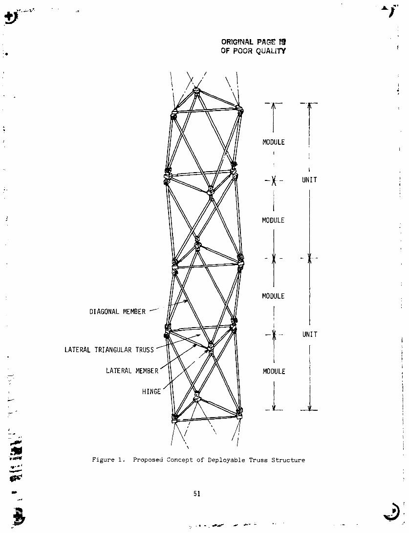
The c o n c e p t of t h e deployable t r u s s , which t h e a u t h o r proposes h e r e i n , is e s s e n t i a l l y a t r u s s of v a r i a b l e geometry. Figure 1 i l l u s t r a t e s a t y p i c a l example of t h e p r o p o s e d c o n c e p t f o r t h e deployable t r u s s s t r u c t u r e . The fundamental module of t h e t r u s s is an o c t a h e d r a l t r u s s composed of a p a i r of l a t e r a l t r i a n g u l a r t r u s s e s and s i x d i a g o n a l members. The two ad jacen t modules, which s h a r e t h e l a t e r a l t r u s s , compase a r e p e a t i n g u n i t of t h e t r u s s . Thus , t h e r e p e t i t i m of t h e u n i t i n t h e l o n g i t u d i n a l d i r e c t i o n forms t h e whole s t r u c t u r e uf t h ~ l deployable t r u s s .
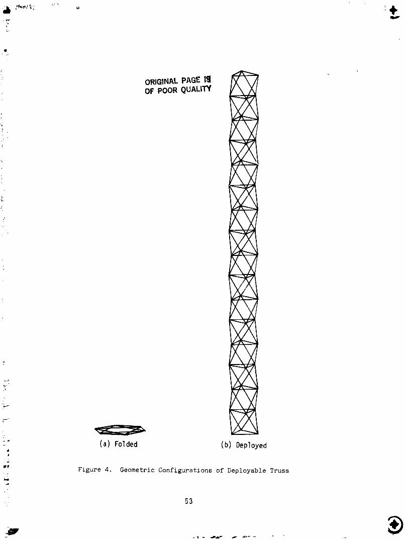
A p a r t of Figure 1 i s en la rged and shown i n Figure 2 , which I l l u s t r a t e s t h e v i c i n i t y around a l a t e r a l t r i a n g u l a r t r u s s . The d e t a i l s of a l a t e r a l member a r e shown i n Figure 3. Th i s member, which is a t e l e s c o p i n g beam whose l e n g t h c a n v a r y , c o n t a i n s i n s i d e t h e t u b u l a r s e c t i o n a n e l a s t i c t e n s i l e s p r i n g t h a t is connected t o b o t h e n d s of t h e beam. I n a d d i t i o n , a l a t c h i s i n s t a l l e d i n t h e beam t o f i x i t s l e n g t h a t t h e s h o r t e s t s t a t e . Figures 4a and 4b i l l u s t r a t e t h e p u r e l y g e o m e t r i c c o n f i g u r a t i o n of t h e t r u s s i n t h e c o m p l e t e l y fo lded and deployed c o n d i t i o n s , r e s p e c t i v e l y . Figure 5 shows t h e almost fo lded s t a t c of t h e t r u s s .
The ou tward a p p e a r a n c e of t h e deployable t r u s s shown i n t h e preceding s e c t i o n i s known e l s e w h e r e i f i t i s a r i g i d s t a t i c s t r u c t u r e i n s t e a d o f a s t r u c t u r e o f v a r i a b l e geometry . For i n s t a n c e , i n r e f e r e n c e 4 , t h a t type of t r u s s (geodesic o r i n v e r t e d b a t t e n beam) is s t u d i e d t o v e r i f y t h e t h e o r y of con t inuum a n a l o g y f o r l a r g e s p a c e s t r u c t u r e s . Ac tua l ly , t h i s t r u s s i s one of the most e f f i c i e n t l ight-weight s t r u c t u r e s u s i n g t h e minimum number of component members. I n t h i s s e c t i o n , t h e au thor shows t h e geometric t r a n s - format ion by which t h e t r u s s can be t r a n s f e r r e d t o a compact c o n E i g u r a t i o n . With mechanisms i n s t a l l e d i n t h e t r u s s a s descr ibed i n t h e previous s e c t i o n , t h e t r u s s becomes deployable.
The geometric t r ans fo rmat ion expla ined i n t h i s s e c t i o n is t h e mode where t h e fo lding/deploying is c a r r i e d o u t s imul taneously through t h e whole s t r u c t u r e . Let i t be c a l l e d t h e s imul taneous mode t r ans fo rmat ion .
LATE RAl
ORIGINAL PAGE R3 OF POOR QlJALiTY
MODULE I
- 1. -
1 MODULE
- I - MODULE
I I
-I I
MODULE
-
F i g u r e 1. Proposed Concept o f Deployable T r u s s S t r u c t u r e
5 1
. . , - .a&- d d m - - .. .
!
I
UNIT
1
- I
I -.. .-
UNIT

ORlGiNAL PAGE 19 OF POOR QUALITY
TUBE
Figure 3 . Detai ls o f Lateral Member
MEMBER
MEMBER
ORIGINAL PAGE lg OF POOR QUALIW
( a ) Folded (b ) Deployed
Figure 4. Geometric Configurations of Deployable Truss

ORIGINAL PAGE 13 OF POOR QUALIN
ORIGINAL PAGE 19 OF POOR QUALlN
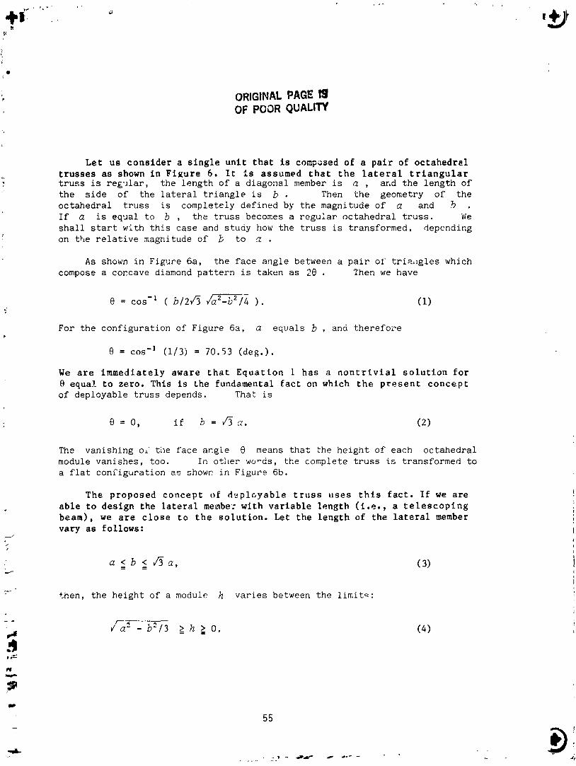
Let us consider a s ing le uni t t h a t i s cocposed of a pa i r of octahedral t russes a s shown i n F igu re 6. I t i s assumed t h a t t h e l a t e r a l t r i a n g u l a r t r u s s i s r e g ~ l a r , t h e l e n g t h o f a d i a g o n a l member i s a , and t h e l e n g t h o f t h e s i d e o f t h e l a t e r a l t r i a n g l e is b . Then t h e geometry o f t h e o c t a h e d r a l t r u s s is comple tc iy d e f i n e d by t h e magnitude o f a and .? . If a is equa l t o b , t h e t r u s s becomes a r e g u l a r o c t a h e d r a l t r u s s . We s h a l l s t a r t wi th t h i s c a s e and s t u d y how t h e t r u s s is t r ans fo rmed , depending on t h e r e l a t i v e magnitude o f b t o a .
A s shown i n Figl i re 6a, t h e f a c e a n g l e between a p a i r o f t r i a i g l e s which compose a coccave diamond p a t t e r n is t aken a s 20 . Then we have
For t h e c o n f i g u r a t i o n of F igu re 6a, a e q u a l s b , and t h e r e f o x
8 = cos-' (1 /3 j = 70.53 (deg.).
We a r e immediately aware t h a t Equat ion 1 has a n o n t r i v i a l s o l u t i o n f o r 8 equal t o zero. This i s the fundamental f ac t on which t h e p r e s e n t concept of dep loyab le t r u s s depends. Thak is
The v a n i s h i n g or' t i le f a c e a n g l e 8 means t h a t :he h e i g h t o f each o c t a h e d r a l module v a n i s h e s , t oo . I n o t l ~ e r words, t h e complete t r u s s is t r ans fo rmed t o a f l a t c o n r i g u r a t i o n a s shown i n F igu ro 6b.
The proposed concept o f d e p l ~ ~ y a b l e t r u s s uses t h i s f a c t . I f we are able t o design the l a t e r a l member with variable length ( i . e . , a t e l e s c o p i n g beam), we a r e c l o s e t o t h e so lu t ion . Let the length of the l a t e r a l member vary a s follows:
a r b - < = &a,
t h e n , t h e h e i g h t of a module h v a r i e s between t h e l i m i t = :
ORIGINAL PAGE 19 OF POOR QUALrrY
Deplo
(b ) Folded c , I
F igwe 6. Repoatin2 Unit of Truss
T h i s means t h a t , by e x t e n d i n g t h e l a t e r a l members by a f a c t o r of h 8 t he height of the t r u s s should v a ~ i s h .
See F igu re 3 f o r a n example of t h e l a t e r a l t e lescoping member. This member cons i s t s of an ex t e rna l tube, an inner tube, a t e n s i l e e l a s t i c sp r ing i n s i d e t h e t u b e , and a l a t c h mechanism t h a t i s ac tua t ed when t h e member is shortened t o a de f ined l e n g t h . The d f agonal members a r e f i x e d l e n g t h members. Although the hinge mechanism is not shown i n d e t a i l , i t is designed t o follow the movement of t he t russ . Figure 5 shows t h e shape of t h e t r u s s a t a lmos t f u l l y f o l d e d s t a t e . T h i s r a t h e r s t r a n g e ro id ing mechanism may be somewhat beyond one's ins igh t . It i s e a s i e r f o r one t o unde r s t and t h e mechanism through a three-dimensional k i n e t i c model.
GEOMETRIC TRlLYSFORMATION OF THE TRUSS (SEQUENTIAL MODE)
Theoret ical ly speaking , a geome t r i c t r a n s f o r m a t i o n i n a s e q u e n t i a l mode is p o s s i b l e i n which each module i s deployed successively and o the r modules remain fixed. Because t h e s e q u e n t i a l mode i s i m p ~ r t a n t from t h e point of view of deployment cont ro l , we w i l l s tudy t h a t mode i n t h i s section.
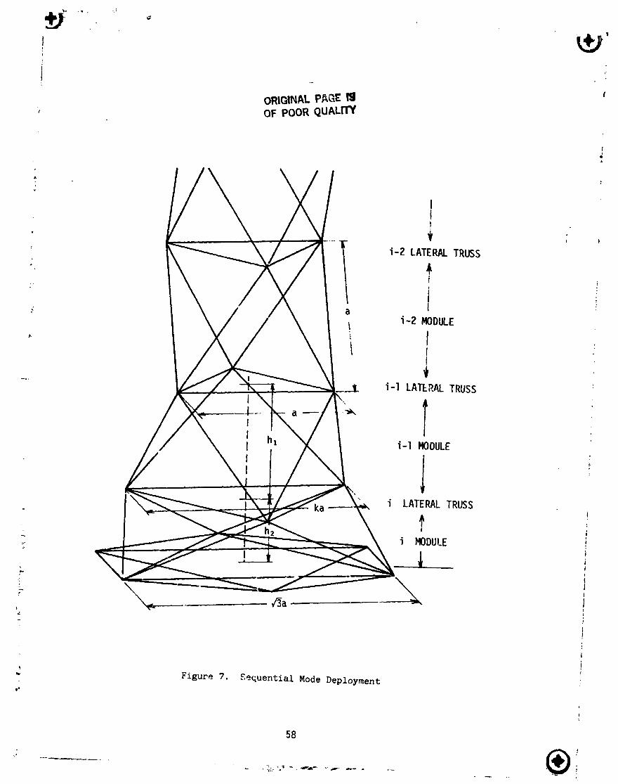
Figure 7 shows the zone of t he t r u s s where t h e s e q u e n t i a l deployment i s underway. For c l a r i t y of explanat ion, it is b e t t e r t o d iv ide t h e whole t r u s s i n t o the following three zones: t he deployed zone, the t r a n s i e n t zone, and t h e folded zone. It is assumed t h a t the trcss comprises n l a t e r a l t r i an - glilar t r u s se s and n-1 nodules . The p r e v i o u s l y mentioned t h r e e zones a r e explaine2 3s follows:
Deployed Zone - Trans t en t Zono Folded Zone
Latera l t r u s s 1,2,3,..... i-1 i i+l,.....
Module 1,2,3,......1-2 i-1, i i , i + l , . . . The important f a c t i s t h a t t h e r e e x i z t s a geome t r i c t r a a s f o r m a t i o n
which a l l o w s t h e c o n t r a c t i o n o f the i - th l a t e r a l t r i a n g u l a r t r u s s and the following deployment of the (i-1)-th and i - t h modules w i thou t i n t e r f e r i n g with o ther zonen of the t russ .
The sequence of motions of t he t r u s s , which c o n s t i t u t e s t he cont rac t ion of the i-th l a t e r a l t r u s s , is explained as f o l i ~ w s : When the i - th t r i angu la r t r u s s s t a r t s c o n t r a c t i n g , i t is r a i s e d from the base and t h e i - t h module s t a r t s t o deploy. Before t h a t , the (i-1)-th module is p a r t i a l l y dep loyed ,
ORIGINAL PBGE 19 OF POOR QUALm
Figure 7. Sequential Mode Deployment

and is continuing to deploy. When the i-th lateral truss finishes its contrac- tion and is latched, the (i-1)-th module completes the deployment. The se- quence of this process is illustrated in the series of figures in Figure 8.
The relation between the length of the diagonal membx a , the lenqth of the lateral member b , and the height of the morhle h is obtained easily by using Figure 7. If a and b are conrected with the variable parameter .Ic ,
b = k-a, where J ? I k l l , -
then, the heights of the modules are
h , = / ( 2 + k - k 2 ) 1 3 - a , ( (i-1)-th module ) (6)
= m- k2/3 0. ( i-th module ) (7)
From a practical standpoint, the sequential mode transformation possesses a great ~dvantage over the simultaneous one. This is because in the former case the c!eploying/folding takes place near the base and thus design of the mechanism is simpler. The outer truss is then al~ays extending from the base as a rigid structure.
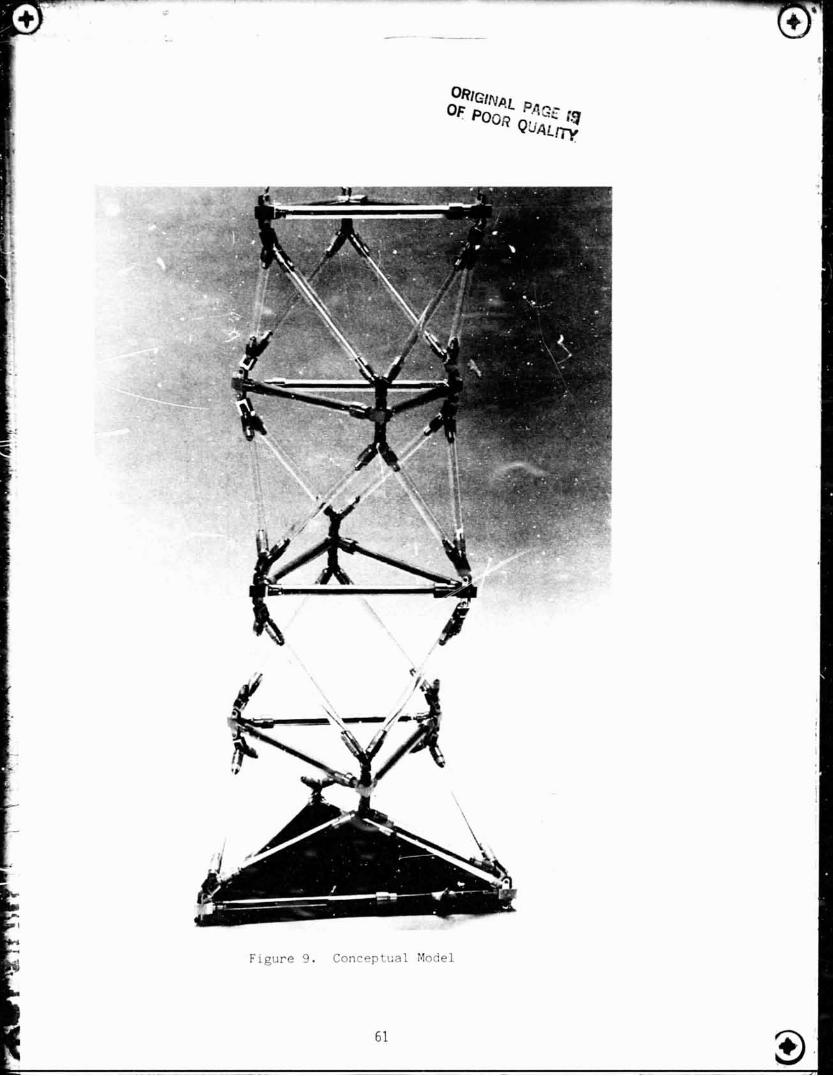
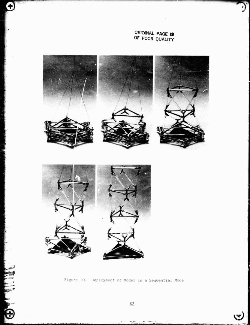
C0NCEPTUF.L MODEL
Although 'here is no doubt of the validity of the geometric transtcrma- tions, a model i . 3 ~ been constructed to demonstrate the concept. This model, made of acrylic glass tubes and aluminum hinges, is shown in Figure 9. The deployment of the modtl in a sequential mode is shown in the series of photos in Figure 10. The model ;*arks as expected and demonstrates the validity of the geometric ttansCorrnatfon.
CONCLUDING REMARKS
A new concept for the one-dimensional deployable truss structure is presented. The deployed configuration of the structure cmsists of the repetitlon of an octahedral truss module longitudinally, arid thus is exactly the so-called "geodesic beam" structure. The principal mechanical feature

ORIGINAL PAGE 19 OF POOR QUALlTY
of the truss is that the lateral members comprising the lateral triangular truss are telescoping beams. Contraction of the lateral members results in deployment of the truss. The geometric transformation of this truss of variable geometry is presented. It is shown that both simultaneous and sequential modes of deployment are possible. The validity of the concept is verified by means of a conceptual model. Though the study is in its initial phase, this concept for the deployable truss structure seems to have qualities suitable for space applications.
ACKNOWLEDGEMENT
The author wishes to thank to Mr. Kenichi Suzuki of Godo Seisakusho for his contribution in designing the conceptual model.
REFERENCES
1. Mikulas, Martin M., Jr., and Harold G. Bush, "Advances in Structural Concepts, Large Space Antenna Systems Technology - 1982," NASA CP-2269, November 1982, pp. 258-283.
2. Greenberg, H. S., "Development of Deployable Structures for Large Space Platforms," NASA CR-170689, December 1982.
3. Cox, R. L., and R. A. Nelson, "Development of Deployable Structures for Large Space Platforms," NASA CR-170690, December !982.
4. Noor, A. K., M. S. Anderson and W. H. Greene, "Continuum Models for Beam- and Plate-Like Lattice Structures," AAZA J., - 16 (12), December 1978.