Embed Size (px)
Citation preview

© 2019 JETIR January 2019, Volume 6, Issue 1 www.jetir.org (ISSN-2349-5162)
JETIR1901A56 Journal of Emerging Technologies and Innovative Research (JETIR) www.jetir.org 449
Design and Manufacturing of Test Rig for estimation
of Shear Strength and Bending Behavior
1Nikhil Patil, 2Shubham Ilag, 3Amol Junnarkar, 4Nikhil Kulkarni 1N. N. Patil, 2S. M. Ilag, 3 A. S. Junnarkar, 4N. P. Kulkarni
1Department of Mechanical Engineering, 1,2,4K.K.Wagh College of Engineering, Nashik, Maharashtra, India, 3Jawahar Institute of Technology, Nashik, Maharashtra, India
Abstract— The mechanical properties of engineering materials determines their application and serviceability. The
designing of a test rig is aimed to estimate mechanical properties of materials. It is designed to evaluate shear strength and
bending behavior by using combine action of compression-shear loading. Test rig features attachments and fixtures to
conduct different tests by application of compressive force. The test specimen taken under observation is of smaller cross
section which helps to lower the effort required. The estimated values can be rectified by using different methods like Split-
Hopkinson pressure-shear testing method, mathematical model, simulation software etc. This paper represents key
parameters of shear behavior of specimen under different testing conditions and using them for manufacturing of a test rig
for evaluation of the same.
Index Terms— Compression-shear loading, Split-Hopkinson pressure-shear testing, bending behavior, Truss etc.
I. INTRODUCTION (HEADING 1)
Main purpose of this paper is to understand the design and Manufacturing of Test rig for estimation of Shear Strength and Bending
Behavior. Design and mechanism is kept simple. The concept of the project is such that the knowledge of designing, mechanism and
manufacturing are increased.
This project consists of designing and development of a testing rig to determine the shear strength and bending behavior of
specimen with such ease so that the material analysis can be done with greater precision. This project can be directly applied for
commercial purposes to produce number of identical machines as a testing equipment.
This project includes the process of designing and fabrication of different parts of this Test rig considering economical and
ergonomic factor for manufacturers to use. Main purpose of this project is to develop new technology for testing that would be more
accurate, precise so as to make things easier than before. After the design and manufacturing, it was transformed to a sublimely
productive equipment which made the objectives accomplished.
II. PROBLEM FORMULATION
We are going to do design and development of Testing rig means for accurate estimation of mechanical properties like shear
strength and bending behavior of random material in practice, usually of smaller cross-section.
Concept and Objective of the machine is explained below
a. Concept
By introducing a low cost machine so as to overcome various limitations with the current traditional method. The concept of the
work is,
(1) Development of simple, user-friendly test rig to achieve ease in maintenance
(2) To identify various process variables.
(3) Fabrication of parts by using easily available and higher strength materials considering their price too.
(4) Analysis of components using finite element analysis that will help in strengthening and reducing the weight of components.
(5) Achieving higher reliability and serviceability to create benchmark in estimating accurate values.
b. Objective
The main objective of this project is to overcome the traditional method,
(1) To design and manufacture a test rig for determination of shear strength and bending behavior of specimen.
(2) To develop an alternative method for estimation and verification of estimated values of mechanical properties of particular
material in practice.
(3) To design components of test rig and perform their analysis on suitable software and strengthen them against failure
(4) To maintain sound engineering practices and standards during manufacturing of test rig.
III. DESIGN AND SPECIFICATIONS OF THE TEST RIG
(1) Strengths and permissible stresses of materials
© 2019 JETIR January 2019, Volume 6, Issue 1 www.jetir.org (ISSN-2349-5162)
JETIR1901A56 Journal of Emerging Technologies and Innovative Research (JETIR) www.jetir.org 450
(1) Shear strength of test specimen, τ = 250 N/mm2
(2) Crushing strength of Bush, σcr = 580 N/mm2
(3) Crushing strength of Eye and Fork, σcref = 380 N/mm2
(4) Shear strength of Eye and Fork, σsef = 190 N/mm2
(5) Crushing failure of Bush in Eye, σcrbe = 133.33 N/mm2
(6) Crushing failure of Bush in Fork, σcrbf = 133.33 N/mm2
(7) Crushing failure of Eye, σe = 66.67 N/mm2
(8) Crushing failure of Fork, σf = 66.67 N/mm2
(2) Design of Frame body
(1) Working length of frame, Lw = 320 mm
(2) Diameter of support column, Dc = 30 mm
(3) Upper plate dimension, L × B × H = 360 mm × 220 mm × 50 mm
(4) Outer diameter of Tabular side member, Do = 19 mm
(5) Thickness of Tabular side member, t = 2 mm
(3) Design of Bolt
(1) Type of bolt used = Hexagon slot headed bolt
(2) Core diameter of bolt, dc = 8 mm
(3) Nominal diameter of bolt, dm = 10 mm
(4) Specifications of hydraulic system
(1) Standard cylinder bore diameter, D = 60 mm
(2) Total hydraulic force, F = 50 kN
(3) Total hydraulic pressure, p = 17.68 MPa
(4) Power requirement, P = 2000 W, hence 2.2 KW, 3 HP motor is selected.
IV. MANUFACTURING PHASE AND ASSEMBLY
Prior to manufacturing of original fixture, we have decided to manufacture a prototype of our design. So we managed to build
wooden fixture of the same size. That fixture helped us to visualize actual size of fixture. Also, modification of some parts according
to assembly point of view was possible due to wooden fixture.
Important components of the Test rig are:-
(1) Fixture.
(2) Bush.
(3) Base plate with Guide ways.
(4) Truss.
(5) L-Brackets.
(6) Bolts.
(7) Hydraulic system.
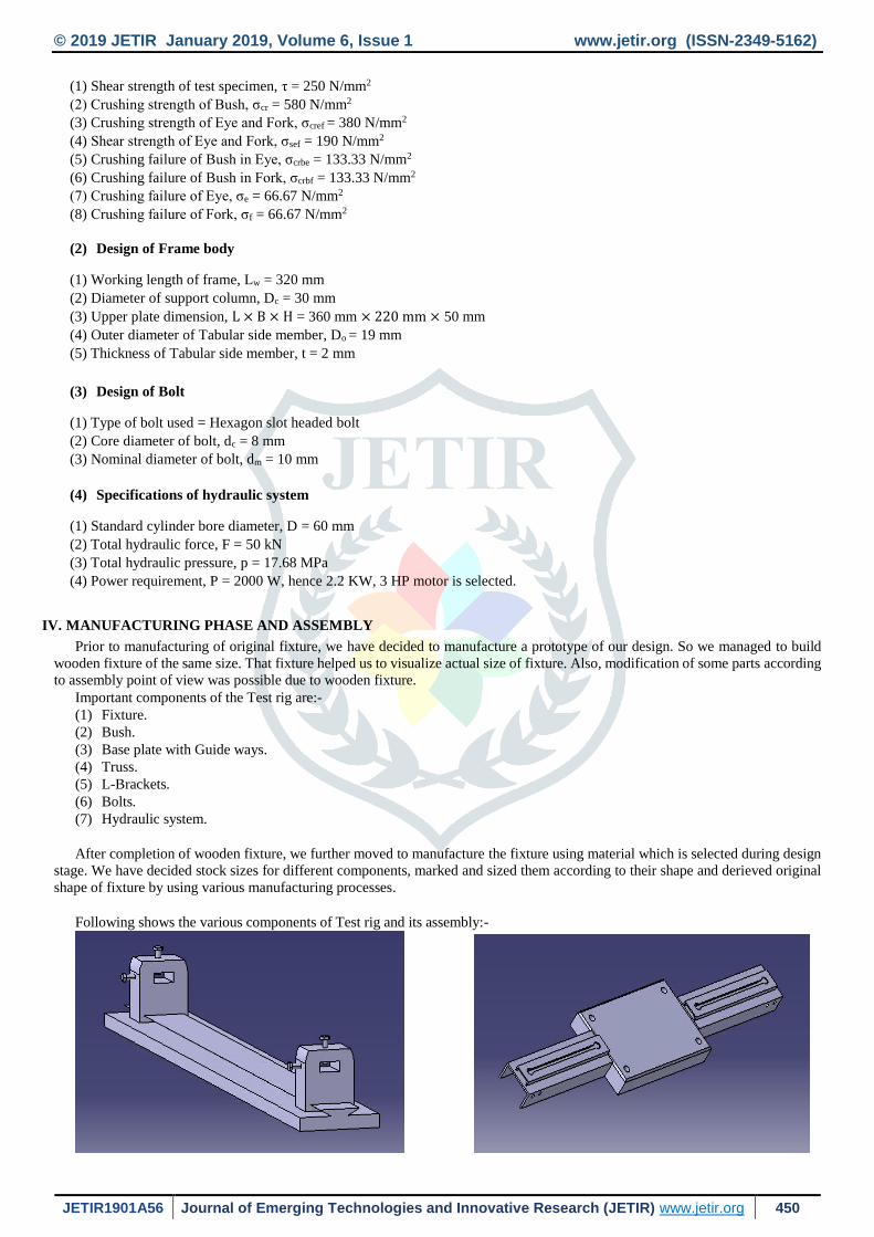
After completion of wooden fixture, we further moved to manufacture the fixture using material which is selected during design
stage. We have decided stock sizes for different components, marked and sized them according to their shape and derieved original
shape of fixture by using various manufacturing processes.
Following shows the various components of Test rig and its assembly:-

© 2019 JETIR January 2019, Volume 6, Issue 1 www.jetir.org (ISSN-2349-5162)
JETIR1901A56 Journal of Emerging Technologies and Innovative Research (JETIR) www.jetir.org 451
Fig. 1 CAD Model of Bending Fixture Fig. 2 CAD model of Lower Plate
’
Fig. 3 CAD model of Support Column Fig. 4 CAD model of Upper Plate
Fig. 5 CAD model of Tubular Side Member Fig. 6 CAD model of Setup Showing Bolt
Fig. 7 CAD Model of Shear Fixture Fig. 8 Wooden Prototype of Fixture

© 2019 JETIR January 2019, Volume 6, Issue 1 www.jetir.org (ISSN-2349-5162)
JETIR1901A56 Journal of Emerging Technologies and Innovative Research (JETIR) www.jetir.org 452
Fig. 9 Final Assembly of Test Rig after Welding
V. TESTING AND ANALYSIS
The stress analysis helps you identify where structures are meeting expectations and how we can improve on others. Finite
element analysis provides a mean to examine and visualize the stress-strain results while operating. In this chapter, ANSYS - FEA
analysis of some load bearing components is done and results are recorded and examined.
Fig. 3 Equivalent stress on Fixture
So applying above static condition with gradual load application, the Finite Element Analysis of Fixture is done in order to seek
whether it can sustain the maximum applied pressure or not.
Result shows that the maximum stress is seems to be 129 MPa.
The yield stress, Syt = 540 MPa.
So, The Factor of Safety (FOS) = Yield Stress (Syt)/129 = 4.18 means design is safe.

© 2019 JETIR January 2019, Volume 6, Issue 1 www.jetir.org (ISSN-2349-5162)
JETIR1901A56 Journal of Emerging Technologies and Innovative Research (JETIR) www.jetir.org 453
VI. RESULTS
Fig. 4 Directional Deformation of Fixture
The result of the analysis done by the ANSYS is that
(1) The maximum stress is on the one edge of the Fixture.
(2) Deformation of the Fixture will start from one side as the pressure is given from the bottom side by the hydraulic cylinder.
(3) The material used can sustain stress up to 540 MPa.
VII. CONCLUSION
This work represents the design of a Hydraulic powered Test rig for estimation of Shear strength and Bending failure. In this
project, the manufactured fixture performed well in testing and produced good results of the specimens. We inspected fixture as
well as whole setup for any failure, but the setup withstood loading conditions. Hence, with respect to this, we conclude that, the
designed and fabricated Test rig for shear strength estimation and verification of bending behavior, stood to expectations and
performed well under different types of loading. The advantage to be derived from the use of this testing equipment far out weights
its shortcomings.
VIII. ACKNOWLEDGMENT
A guide acknowledges the help rendered by Prof. P.J.Pawar, HOD of Production Engineering Department, K.K. Wagh college of Engineering, Nashik, Prof. M.B.Murugkar, HOD of Mechanical Engineering Department, K.K. Wagh college of Engineering, Nashik and Prof. D.R.Patil, HOD of Mechanical Engineering Department, Jawahar Institute of Technology, Nashik for the help
rendered in design and manufacturing of this Test rig.
.
REFERENCES
[1] Indian Standard IS: 5242-1979, Method of Test for determining Shear Strength of Metals, Indian Standards Institution,
MTD3: Mechanical Testing of Metals, pp. 1-6.
[2] Bo Yao, Fangchao Li, Xiao Wang, Gang cheng, Evaluation of the Shear Characteristics of Steel-Asphalt Interface by a
Direct Shear Test Method, International Journal of Adhesion and Adhesives 68 (2016), pp.70-79.
[3] Xin Wang, Zihao Wang, Zhisen Wu, Shear Behavior of Basalt Fibre Reinforced Polymer (FRP) and Hybrid FRP rods as
Shear resistance members, Construction and Building Materials 73 (2014); pp.781-789
[4] S. Sharma, V. M. Chavan, Split Hopkinson Pressure Bar: An Experimental Technique for High Strain Rate Test, Technical
Report, BARC (2011).
[5] Lin Yuliang, Lu Fangyun, Zhao Pengduo, Cui Yunxiao, A New Split Hopkinson Pressure Shear Testing Set, DYMAT
(2009); pp. 583–589.
[6] Poologanathan Keerthan, Mahen Mahendran, Experimental Studies on Shear Behaviour and Strength of Lite-Steel Beams,J.
of Constructional Steel Research, Vol.66, pp.1309-1319.
[7] V.B. Bhandari, Design of Machine Elements, Tata McGraw-Hill Education, first edition, 330-334, 2010.
[8] Dr. S.K. Somani, Machine Design, McGraw-Hill Education, Indian edition, 24.1-24.15, 2008.