Embed Size (px)
Citation preview

http://www.iaeme.com/IJMET/index.asp 42 [email protected]
International Journal of Mechanical Engineering and Technology (IJMET)
Volume 8, Issue 10, October 2017, pp. 42–52, Article ID: IJMET_08_10_006
Available online at http://www.iaeme.com/IJMET/issues.asp?JType=IJMET&VType=8&IType=10
ISSN Print: 0976-6340 and ISSN Online: 0976-6359
© IAEME Publication Scopus Indexed
DESIGN AND MANUFACTURING OF 2-STAGE
SPEED REDUCER FOR A BAJA ALL TERRAIN
VEHICLE
Vijay Kanase, Dnyanada Rane, Vishal Dongare, Rhuturaj Shinde, Atul Tangade
Department of Mechanical Engineering,
Pimpri Chinchwad College of Engineering, Pune, India
ABSTRACT
The gearbox designed and fabricated should be reliable, safe and cost effective. It
should be able to transmit sufficient power and torque to generate the required
traction at the wheels at a particular rpm. The vehicle should be able to complete all
the dynamics events and the endurance race satisfactorily. The reduction ratio of the
gearbox was finalized after considering various road resistances, maximum
acceleration and grad ability performance. Standard procedures have been adopted
for design of gears, shafts and casing of the gearbox.
Bearing selection is also done according to standards specified. The analytical
calculations are evaluated using Hypermesh for finite element analysis. Machining of
components is done after exploring various methods and further heat treated to
improve their wear strength. After the completion of the ATV prototype, the 2-stage
speed reducer has undergone rigorous testing to check its durability.
Key words: Design, Speed Reducer, Gearbox, Baja, Transmission, Traction, Driving
resistances, Reduction ratio, Gears, Shaft, Casing, Bearing, Torque.
Cite this Article: Vijay Kanase, Dnyanada Rane, Vishal Dongare, Rhuturaj Shinde,
Atul Tangade, Design and Manufacturing of 2-Stage Speed Reducer for a Baja all
Terrain Vehicle, International Journal of Mechanical Engineering and Technology
8(10), 2017, pp. 42–52.
http://www.iaeme.com/IJMET/issues.asp?JType=IJMET&VType=8&IType=10
1. INTRODUCTION
The main goal when developing a vehicle transmission is to convert the power from the
engine into vehicle traction as efficiently as possible, over a wide range of road speeds. This
has to be done ensuring a good compromise between the number of speeds, climbing
performance, acceleration and fuel consumption of the vehicle. Technical and technological
advances have to be taken into account, as do operational reliability and adequate service life.
[1]
Gisbert Lechner, Harald Naunheimer (1999) [1] have given full account of the
development process for automotive transmission, detailed study of driving resistances,
Design and Manufacturing of 2-Stage Speed Reducer for a Baja all Terrain Vehicle
http://www.iaeme.com/IJMET/index.asp 43 [email protected]
various characteristics for transmission variables and drivetrain power losses. Selection of
optimum gearbox ratio considering maximum acceleration and gradability is also analyzed.
Budynas, Nisbett (2008) [3] have explained the basics of machine design, including design
process, engineering mechanics and materials and failure prevention under static and variable
loading conditions. Analysis of spur gears to resist bending failure of teeth as well as pitting
failure of tooth surfaces using AGMA standard 2001: D04 is done.
Reza N. Zajar (2013) [2] has explained vehicle dynamics concepts in detail. Effect of CG on
vehicle dynamics as well forward vehicle dynamics, tire dynamics, and driveline dynamics.
Forward dynamics refers to weight transfer, accelerating, braking, engine performance, and
gear ratio design.
Tushar N. Khobragade, P. Priadarshani (2008) [7] have studied static analysis of gearbox
casing using FEA softwares Hypermesh/Optistruct and Ansys 11.0. The optimum design is
achieved using iterative design and analysis procedure. The various loading and boundary
conditions are given for static analysis of gearbox casing.
2. CALCULATING GEARBOX RATIO ACCORDING TO TRACTION
REQUIREMENT
2.1. Assumptions
Weight Distribution: 40% - Front; 60% - Rear
Total Weight of the Vehicle (with driver): 220kg
Static coefficient of friction: 0.85
2.2. Driving Resistance
The anticipated driving resistance is an important variable when designing vehicle
transmission. [1] Driving resistance is made up of:
Wheel resistance or Rolling resistance FR
Air resistance FL
Gradient resistance Fst
Acceleration resistance Fa
2.2.1. Rolling Resistance FR:
Wheel resistance comprises the resisting forces acting on the rolling wheel. It is made up of
rolling resistance, road surface resistance and slip resistance. [1]
FR= fR x GR fR =
(1)
Where, fR = rolling resistance coefficient,
GR = wheel load,
e = eccentricity,
rdyn = dynamic wheel radius.

Vijay Kanase, Dnyanada Rane, Vishal Dongare, Rhuturaj Shinde, Atul Tangade
http://www.iaeme.com/IJMET/index.asp 44 [email protected]
Table 1 Values of Rolling Resistances fR. [1]
Road surface fR
Very good earth tracks 0.045
Bad earth tracks 0.16
Loose sand 0.15-0.13
Smooth tarmac road 0.01
Bad worn road surface 0.035
Smooth Concrete Road 0.011
Figure 1 Rolling Resistance [1]
2.2.2 Air Resistance FL:
The air resistance is made up of the pressure drag including induced drag (turbulences
induced by differences in pressures), surface resistance and internal (through-flow) resistance.
[1]
FL =
ρL cW A v
2 (2)
Where, ρL = air density= 1.199kg/m3,
cW = coefficient of drag=1.2,
A = projected frontal area in m2,
v = speed of vehicle.
2.2.4. Acceleration Resistance Fa:
In addition to the driving resistance occurring in steady state motion (v = constant), inertial
forces also occur during acceleration and braking. The total mass of the vehicle mF and the
inertial mass of the rotating parts of the drive acceleration or brakes are the factors influencing
the resistance to acceleration [1]
Fa = λ mF a (3)
λ = Rotational inertia coefficient which represents proportion of total mass that is rotary
2.2.3. Gradient Resistance Fst:
The gradient resistance or downhill force relates to the slope descending force and is
calculated from the weight acting at the centre of gravity. [1]
FSt = mF g sin(αSt) (4)

Design and Manufacturing of 2-Stage Speed Reducer for a Baja all Terrain Vehicle
http://www.iaeme.com/IJMET/index.asp 45 [email protected]
Where, mF = mass of vehicle,
g = acceleration due to gravity (m/s2),
αSt = grade angle =45deg
Figure 2 Free Body Diagram of a Vehicle on an Inclined Plane [1]
2.2.5. Total Driving Resistance
F = FR + FL + FST + Fa (5)
F = mF g (fR cos(αSt) + sin(αSt)) +
ρL cW A v
2 + λ mF a (6)
2.3. Traction Available
The traction available at wheels can be found out from engine characteristics. [1]
Traction =
(7)
Where TM is the max torque=18.9N-m
Gr is the overall gear ratio
ɳall is the total transmission efficiency=0.85(assumed)
rdyn is the dynamic radius of the wheel.(22x7-10)=0.276m
2.4. Gearbox Reduction Ratio
2.4.1. Selecting the Largest Power-Train Ratio
At the drive wheels, a balance must be struck between the required acceleration and gradient
road surface, trailer load. The gearbox reduction ratio is calculated by equating traction
available at wheels to the traction required. [1]
Maximum traction available = Maximum traction required
= mF g (fR cos(αSt) + sin(αSt)) +
ρL cW A v
2 + λ mF a (8)

Vijay Kanase, Dnyanada Rane, Vishal Dongare, Rhuturaj Shinde, Atul Tangade
http://www.iaeme.com/IJMET/index.asp 46 [email protected]
3. DESIGN OF TWO STAGE SPEED REDUCER
The overall reduction ratio obtained in previous step is split into two stages using the formula:
i1 = 0.76 × iT0.65
i2 =
(9)
3.1. Design of Gears According to AGMA 2001-D04
The intent of the AGMA strength rating formula is to determine the load which can be
transmitted for the design life of the gear drive without causing root fillet cracking.
The module of gears for each stage is obtained from the following formula [6]
d =
; m =
(10)
C is Center distance between input to output gear and G is the overall gear ratio. The gears
are designed using AGMA 2001-D04 standard procedure considering factor of safety for spur
gear bending and wear with stress cycles 107 and reliability of 0.99. The gears were
manufactured using hobbing cutter with pressure angle of 200 with minimum number of teeth
on pinion as 18.
3.1.1. Bending Strength Equation
The fundamental formula for bending stress number in a gear tooth is: [3]
σ = wt*ko kv ks*
*
(11)
where, Wt = tangential transmitted load, lbf (N),
Ko = overload factor,
Kv = dynamic factor,
Ks = size factor,
Pd = transverse diametral pitch,
F = face width of the narrower member, in (mm),
Km = load-distribution factor,
Kb = rim-thickness factor,
J = geometry factor for bending strength (which includes root fillet stress-concentration
factor Kf).
Gear bending endurance strength: [3]
σall =
*
(12)
Where, KT = Temperature factor,
KR = Reliability factor,
YN = Stress cycle factor.
Bending Factor of Safety: [3]

Design and Manufacturing of 2-Stage Speed Reducer for a Baja all Terrain Vehicle
http://www.iaeme.com/IJMET/index.asp 47 [email protected]
Sf =
(13)
3.1.2. Wear Strength Equation: [3]
σc = Cp (Wt Ko Kv Ks
)1/2
(14)
Where, σc = contact stress number, lb/in2,
Cp = elastic coefficient, [lb/in2]0.5
,
Wt = transmitted tangential load lb,
Ko = is overload factor,
Kv = is dynamic factor,
Ks = size factor,
Km = load distribution factor,
Cf = surface condition factor for pitting resistance,
F = net face width of narrowest member, inch,
I = geometry factor for pitting resistance,
d = operating pitch diameter of pinion, inch.
Gear contact endurance strength: [3]
σc,all=
(15)
Where, Sc = allowable contact stress number lb/in2,
ZN = stress cycle factor for pitting resistance,
CH = hardness ratio factor for pitting resistance,
St = safety factor for pitting,
KT = temperature factor,
KR = reliability factor.
Wear factor of safety: [3]
SH=
(16)
4. DESIGN OF SHAFT
The forces acting on the gears were calculated using the free body diagram. These forces are
then considered for the design of shafts and the selection of bearings. [4]
4.1. ASME Code for Shaft Design
τmax = 0.30 Syt (17)

Vijay Kanase, Dnyanada Rane, Vishal Dongare, Rhuturaj Shinde, Atul Tangade
http://www.iaeme.com/IJMET/index.asp 48 [email protected]
τmax = 0.18 Sut (18)
If keyways are present the above values are reduced by 25 per cent.
τmax =
√
(19)
σ1 =
[ √
(20)
The diameters of the shafts were calculated using the above formulae, the shear force and
bending moment diagrams were drawn considering the forces acting on the gears and the self-
weight of the gears. [4]
5. BEARING SELECTION:
5.1. Equivalent Dynamic Load
The equivalent dynamic load is defined as the constant radial load in radial bearings (or thrust
load in thrust bearings), which if applied to the bearing would give same life as that which the
bearing will attain under actual condition of forces. [8]
The expression for the equivalent dynamic load is written as,
P = XVFr + YFa (21)
For Spur gears axial loading is zero, P=Fr
Where, P = equivalent dynamic load(N)
Fr = radial load(N)
V = race rotation factor=1 (inner race rotating)
X and Y = radial and thrust load factors=1
5.2. Load-Life Relationship
The life expressed in operating hours using [8]
Lh10=
(22)
The basic rating life of a bearing in accordance with ISO 281 is
Lh10=(
) (23)
Where, L10 = basic rating life (at 90% reliability) [million revolutions]
Lh10 = basic rating life (at 90% reliability) [operating hours]
C = basic dynamic load rating [kN]
P = equivalent dynamic bearing load [kN]
n = rotational speed [r/min]
a = exponent of the life equation
for ball bearings, a = 3
for roller bearings, a = 10/3

Design and Manufacturing of 2-Stage Speed Reducer for a Baja all Terrain Vehicle
http://www.iaeme.com/IJMET/index.asp 49 [email protected]
Figure 3 Layout of 2 stage speed reducer Figure 4 Exploded view of assembly
6. FINITE ELEMENT ANALYSIS
Finite element analysis of gearbox shaft, gears and casing is done using Hypermesh software.
Tangential load is applied on single gear tooth face of integrated pinion shaft and gears. The
static structural analysis was done considering standstill position and sudden application of
load. For analysis of casing the reactions obtained from freebody diagram at bearing position
were applied and the gearbox mounting points were fixed. Load values and stress induced are
mentioned in following tables. [7]
Figure 5
Table 2 FEA of Input Shaft
INPUT SHAFT
Static structural analysis
Syt 880 N/mm2
Maximum stress 466.462 N/mm2
FOS 1.8

Vijay Kanase, Dnyanada Rane, Vishal Dongare, Rhuturaj Shinde, Atul Tangade
http://www.iaeme.com/IJMET/index.asp 50 [email protected]
Figure 5
Table 3 FEA of First Stage Gear
Figure 6
Table 4 FEA of Gearbox Casing
7. MANUFACTURING OF 2-STAGE SPEED REDUCER
In order for gears to achieve their intended performance, durability and reliability, the
selection of a suitable gear material is very important. High load capacity requires a tough,
hard material that is difficult to machine; whereas high precision favors materials that are easy
to machine and therefore have lower strength and hardness ratings. Gears are made of variety
of materials depending on the requirement of the machine. They are made of plastic, steel,
wood, cast iron, aluminum, brass, powdered metal, magnetic alloys and many others. The
final selection should be based upon an understanding of material properties and application
FIRST STAGE GEAR
Static Structural Analysis
Syt 880 N/mm2
Maximum stress 438.647 N/mm2
FOS 2
GEARBOX CASING
Static Structural Analysis
Syt 270N/mm2
Maximum stress 70.641 N/mm2
FOS 4.28
Design and Manufacturing of 2-Stage Speed Reducer for a Baja all Terrain Vehicle
http://www.iaeme.com/IJMET/index.asp 51 [email protected]
requirements. Materials such as SAE8620, 20MnCr5, 16MnCr5, Nylon, Aluminum, etc. used
for automobile gears. Taking into account hardness and machinability of material selected
gear tooth were obtained using hobbing cutter of specified module.To improve wear
resistance case hardening was done to maintain case hardness of 40HRC and 3mm depth.
Bearing Tolerances were achieved by grinding on shafts. [5]
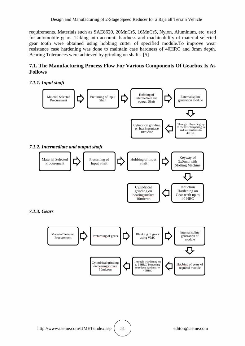
7.1. The Manufacturing Process Flow For Various Components Of Gearbox Is As
Follows
7.1.1. Input shaft
7.1.2. Intermediate and output shaft
7.1.3. Gears
Material Selected Procurement
Preturning of Input Shaft
Hobbing of intermediate and
output Shaft
External spline generation module
Through Hardening up to 55HRC Tempering to
reduce hardness to 40HRC
Cylindrical grinding on bearingsurface
10micron
Material Selected Procurement
Preturning of Input Shaft
Hobbing of Input Shaft
Keyway of 5x5mm with
Slotting Machine
Induction Hardening on
Gear teeth up to 40 HRC
Cylindrical grinding on
bearingsurface 10micron
Material Selected Procurement
Preturning of gears Blanking of gears
using VMC
Internal spline generation of
module
Hobbing of gears of required module
Through Hardening up to 55HRC Tempering to reduce hardness to
40HRC
Cylindrical grinding on bearingsurface
10micron

Vijay Kanase, Dnyanada Rane, Vishal Dongare, Rhuturaj Shinde, Atul Tangade
http://www.iaeme.com/IJMET/index.asp 52 [email protected]
7.1.4. Casing
7.2. Assembly of Gearbox
The assembly of the gearbox was done on the manual press machine available in the
workshop. The load was applied gradually using the hand wheel. Initially all the bearings
were fitted in both the casings. The shafts with gears mounted on them were press fitted in the
bearings on one side. The other side of the casing was then fitted on. A rubber gasket with a
gasket maker was used to seal the gearbox and prevent any leakage. Both the sides of the
casing were then fixed with the help of Allen bolts of size M6.
REFERENCES
[1] Gisbert Lechner, Harald Naunheimer, Automotive Transmissions, Verlag Berlin
Heidelberg Germany: Springer, 1999, pp.58-64,83
[2] Reza N. Jazar, Vehicle Dynamics:Theory and Application, New York: Springer
Science+Business Media, LLC, 2008, pp.53
[3] Budynas−Nisbett, Shigley’s Mechanical Engineering Design, Eighth Edition, USA:
McGraw−Hill Companies, 2008, chapter14, pp.744,745
[4] V.B. Bhandari, Design of Machine Elements, Third Edition, Tata McGraw- Hill
Education, 2010,
[5] Shastri, D., Ramamurthy, S., and Parab, P. Strategies For Automobile Gear Material
Selection, SAE Technical Paper, 2008
[6] Omar D. Mohammad, The Effect Of Center Distance Change On Gear Teeth Engagement
And Stress Analysis, Assistant Lecturer-University of Mosul
[7] Tushar N. Khobragade, P. Priadarshani, Static analysis of gearbox casing, 2008.
[8] SKF Rolling Bearings Catalogue, pp.64
[9] Aditya Patankar, Rohit Kulkarni, Sanket Kothawade and Sameer Ingale, Design and
Development of a Transmission System for an All - Terrain Vehicle. International Journal
of Mechanical Engineering and Technology, 7( 3 ), 2016, pp. 351 – 359 .
[10] Aditya Shahane, Manasi Kathale, Pratik Rathi and Ashank Gujar , Kinematics of Rear
Suspension System for A Baja All - Terrain Vehicle , International Journal of Mechanical
Engineering and Technology 8(8), 2017, pp. 164 – 171 .
Material Selected Procurement
Preturning of gears Machining of casing using VMC or other
milling options
Boring operation on bearing surface to achieve desired
tolerances
Drilling and tapping for Breather, drain plug and sight glass
Buffing operation to get surface finish.