Embed Size (px)
Citation preview

Electronic Power Control
Design and Function
Self-Study Programme 210
Service.

2
Please always refer to the relevant Service Literature
for all inspection, adjustment and repair instructions.
Service literature.
The Self-Study Programme is not a Workshop Manual.
New ImportantNote
With the Electronic Power Control system, the throttle valve is actuated only by an electric motor.This eliminates the need for a Bowden cable between the accelerator pedal and the throttle valve.
It means that the driver input is relayed to the engine control unit via the accelerator pedal.The engine control unit then sends a correspond-ing command to the throttle valve positioner.
By positioning the throttle valve, the engine con-trol unit can regulate engine torque even if the driver has not depressed the accelerator pedal.
The result is better co-ordination between and within the engine management systems.
We will now demonstrate that the Electronic Power Control is more than just a substitute for the Bowden accelerator cable.

3
Introduction . . . . . . . . . . . . . . . . . . . . . . . . . . . . . . . . . . 4
Throttle valve positioning . . . . . . . . . . . . . . . . . . . . . . . . 4
System description . . . . . . . . . . . . . . . . . . . . . . . . . . . . . 5
Control process . . . . . . . . . . . . . . . . . . . . . . . . . . . . . . . . 6
System design . . . . . . . . . . . . . . . . . . . . . . . . . . . . . . . . . 7
What happens and when? . . . . . . . . . . . . . . . . . . . . . . 8
System components . . . . . . . . . . . . . . . . . . . . . . . . . . 10
System overview . . . . . . . . . . . . . . . . . . . . . . . . . . . . . . 10
The engine control unit . . . . . . . . . . . . . . . . . . . . . . . . . 11
The accelerator pedal module . . . . . . . . . . . . . . . . . . 14
The throttle valve control unit . . . . . . . . . . . . . . . . . . . 16
The fault indicator lamp . . . . . . . . . . . . . . . . . . . . . . . . 22
Auxiliary signals . . . . . . . . . . . . . . . . . . . . . . . . . . . . . . 23
Function diagram . . . . . . . . . . . . . . . . . . . . . . . . . . . . 25
Self-diagnosis . . . . . . . . . . . . . . . . . . . . . . . . . . . . . . . 26
Test your knowledge . . . . . . . . . . . . . . . . . . . . . . . . . 30
Table of contents
4
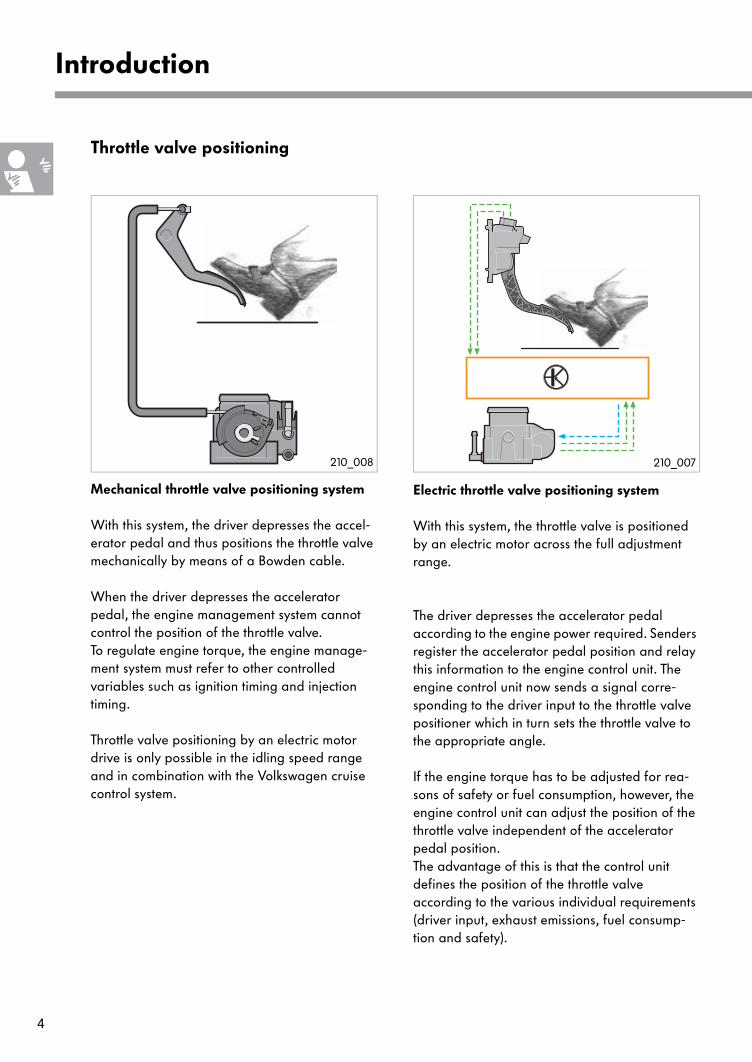
Throttle valve positioning
Mechanical throttle valve positioning system
With this system, the driver depresses the accel-erator pedal and thus positions the throttle valve mechanically by means of a Bowden cable.
When the driver depresses the accelerator pedal, the engine management system cannot control the position of the throttle valve. To regulate engine torque, the engine manage-ment system must refer to other controlled variables such as ignition timing and injection timing.
Throttle valve positioning by an electric motor drive is only possible in the idling speed range and in combination with the Volkswagen cruise control system.
Electric throttle valve positioning system
With this system, the throttle valve is positioned by an electric motor across the full adjustment range.
The driver depresses the accelerator pedal according to the engine power required. Senders register the accelerator pedal position and relay this information to the engine control unit. The engine control unit now sends a signal corre-sponding to the driver input to the throttle valve positioner which in turn sets the throttle valve to the appropriate angle.
If the engine torque has to be adjusted for rea-sons of safety or fuel consumption, however, the engine control unit can adjust the position of the throttle valve independent of the accelerator pedal position. The advantage of this is that the control unit defines the position of the throttle valve according to the various individual requirements (driver input, exhaust emissions, fuel consump-tion and safety).
Introduction
210_007210_008

5
System description
Engine torque control with mechanical throttle valve positioning
The various torque requirements are signalled individually to the engine control unit and then processed.The torque demands cannot be matched opti-mally because the engine control unit cannot access the mechanically adjustable throttle valve directly.
Engine torque control with electric throttle valve positioning
This system permits torque-oriented engine management.
What does this mean?First, the engine control unit gathers all the internal and external torque demands. Then it calculates the necessary control actions. This system is more precise and efficient than the previous system.
Internal torque demands include:
- Start- Catalytic converter heating- Idle speed control- Power limitation - Speed limiting device- Lambda control
External torque demands originate from:- the automatic gearbox (shift point)- the brake system (Traction Control System,
engine braking control)- the air conditioning system
(air conditioner compressor ON/OFF) and- the cruise control system
Internalrequirements
Externalrequirements
Optimalefficiency
210_009
The "tools“ which the engine management system uses to influence the engine torque are:throttle valve, charge pressure, injection timing, cylinder suppression and ignition advance angle.
Enginecontrol unit
6
Introduction
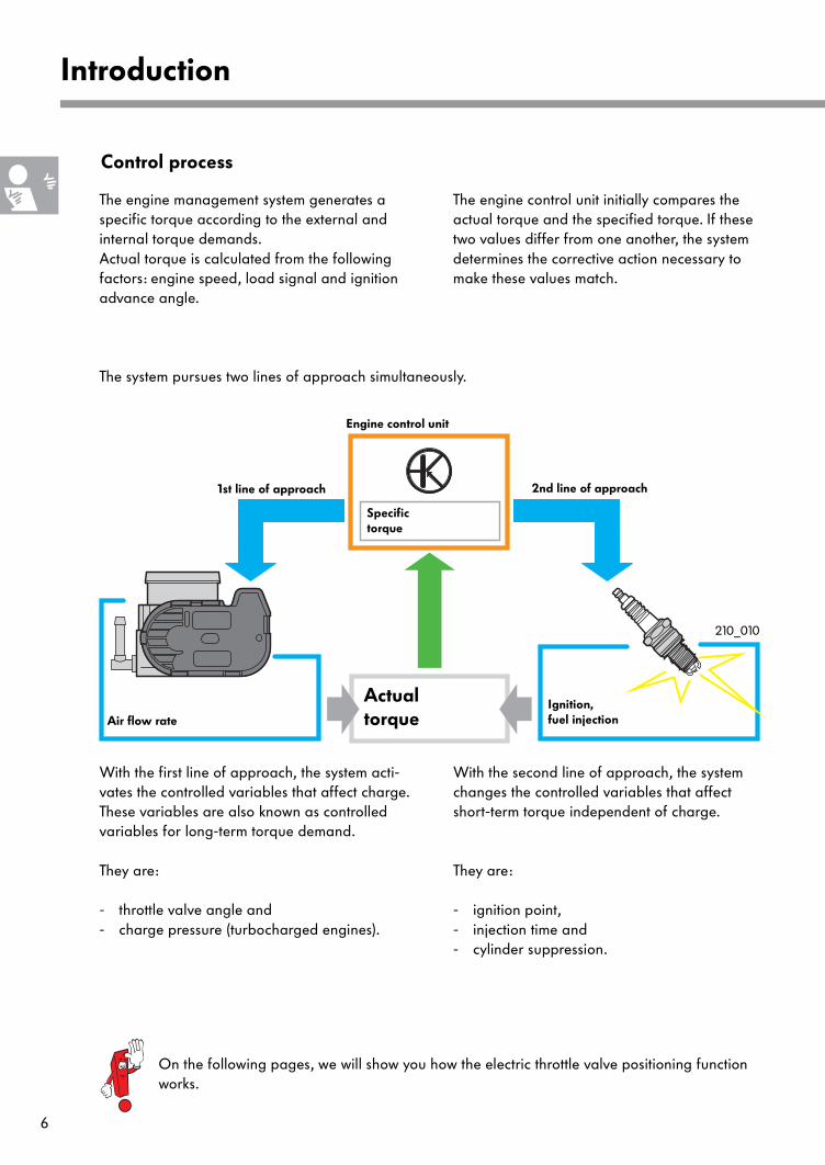
Control process
With the first line of approach, the system acti-vates the controlled variables that affect charge. These variables are also known as controlled variables for long-term torque demand.
They are:
- throttle valve angle and - charge pressure (turbocharged engines).
With the second line of approach, the system changes the controlled variables that affect short-term torque independent of charge.
They are:
- ignition point, - injection time and - cylinder suppression.
Specific torque
ActualtorqueAir flow rate
1st line of approach 2nd line of approach
Ignition, fuel injection
Engine control unit
210_010
The engine management system generates a specific torque according to the external and internal torque demands. Actual torque is calculated from the following factors: engine speed, load signal and ignition advance angle.
The system pursues two lines of approach simultaneously.
The engine control unit initially compares the actual torque and the specified torque. If these two values differ from one another, the system determines the corrective action necessary to make these values match.
On the following pages, we will show you how the electric throttle valve positioning function works.

7
System design
The accelerator pedal module
determines the current accelerator pedal position with its senders and sends a corresponding signal to the engine control unit.
The engine control unit
calculates from this signal how much engine power is required by the driver and converts this information into an engine torque value. For this purpose, the engine control unit activates the throttle valve drive in order to open or close the throttle valve further. When activating the throttle valve drive, the engine control unit makes allow-ance for additional engine torque demand factors such as air-conditioning.
In addition, it monitors the "Electronic Power Control” function.
The throttle valve control unit
is responsible for providing the required air mass flow. The throttle valve drive actuates the throttle valve in accordance with the instructions issued by the engine control unit.The throttle valve angle senders supply the engine control unit with feedback on the position of the throttle valve.
The fault indicator lamp for Electronic Power Control
indicates to the driver that there is a fault in the Electronic Power Control system.
Electronic Power Control comprises:
- the accelerator pedal module together with the accelerator position senders,- the engine control unit, - the throttle valve control unit, and- the fault indicator lamp for Electronic Power Control.
Throttle valve control unit
Accelerator pedal module
Fault indicator lamp
Auxiliary signals
210_011

8
Introduction
What happens and when?
In idling mode
The engine control unit can recognise from the signal voltages of the accelerator position sender that the accelerator pedal is not depressed. The idle speed control process now commences.
The digital idling stabilisation function also supports the idle speed control process.
Engine control unit
Accelerator pedal module
Angle sender for throttle valve drive
Accelerator position sender
Throttle valvecontrol unit
The two angle senders for throttle valve drive sig-nal the current position of the throttle valve to the engine control unit. They are located in the throttle valve control unit.
Throttle valvedrive
The engine control unit activates the throttle valve drive and positions the throttle valve by means of an electric motor.The throttle valve is opened or closed further depending on the extent to which the actual idling speed deviates from the specified idling speed.
210_019
210_060
210_061

9
Pressing the accelerator pedal
The engine control unit can recognise from the signal voltages of the accelerator position sender the extent to which the accelerator pedal is depressed. Using this information, the engine control unit calculates the driver input and posi-tions the throttle valve by actuating the throttle valve drive by means of an electric motor. The engine control unit also controls the ignition timing, the injection timing and, if necessary, the charge pressure.
The engine control unit makes allowance for additional engine torque demand factors when calculating the necessary throttle valve position.
These include: - the speed limiting device - the cruise control system - the Traction Control System (TCS) and- the engine braking control (EBC)
When engine torque is required, the throttle valve can be adjusted even if the driver has not changed the accelerator pedal position.
The two angle senders for throttle valve drive determine the throttle valve position and send a corresponding signal to the engine control unit
210_021
210_062
210_063
TC Air EBC

10
System overview
System components
Sensors Actuators
Brake light switch Fandbrake pedal switch F47
Clutch pedal switch F36
Accelerator pedal module with
accelerator pedal position sender -1- G79 and
accelerator pedal position sender -2- G185
Throttle valve control unitJ338
angle sender 1 for throttle valve drive G187andangle sender 2for throttle valve drive G188
Fault indicator lamp for electric throttle control K132 (Electronic Power Control)
Throttle valve drive G186
Engine control unit J...
Diagnostic connection
Throttle valve control unit J338 with
210_037
Auxiliary signals from:- automatic gearbox,- brake system,- air conditioning system,- cruise control system,
and others
The system components may be different to those shown in this overview depending on vehicle equipment specification.

11
Engine control unit J...
Design
Put in simple terms, the engine control unit com-prises two processing units: the function processor and the watchdog processor.
- The function processor
receives the signals from the sensors, processes them and then activates the actuators. The function processor also checks the watchdog processor.
- The watchdog processor
serves only to check the function processor.
Function processor Watchdog processor
210_012
210_031
Its tasks in the Electronic Power Control:
The EPC calculates from the input signal supplied by the accelerator position sender how much engine power the driver requires and converts this information into an engine torque by means of the actuators. The engine control unit makes allowance for additional functions of the engine management system (e.g. engine speed limitation, road speed limitation and power limitation) and other vehicle systems (e.g. the brake system or the automatic gearbox).
The engine control unit also monitors the "Electronic Power Control“ system in order to prevent malfunctions occurring.

12
System components
Monitoring function
The watchdog processor continuously monitors the functions of the function processor. At the same time, it checks the output signals of the function processor against its own calcula-tions. The function processor and the watchdog processor check each other by means of a query & answer function.
If faults are found, both processors can influence the throttle valve control unit, the ignition and the injection independently from one another in order to shut down the engine.
checksoutput signals
calculatescorrective actions
Act
uato
rs
Sens
ors Output
signal
Output signal
Function processor
Watchdog processor
The watchdog processor checks the function processor with the query & answer function.
Error counter
quer
ies an
swer
s
The watchdog processor queries the function processor with regard to, say, engine speed or ignition advance angle. Then it checks whether the answer is correct. If a wrong answer is given, the error counter of the watchdog processor is incremented.
The engine is shut down after five wrong answers. Five wrong answers can be detected in less than a half second.
210_014
210_013
Act
uato
rs
Sens
ors
Function processor
Watchdog processor
Engine is shut down if necessary

13
The function processor checks the watchdog processor
The function processor gives no answer or gives an answer at the wrong point in time
To monitor the watchdog processor, the function processor deliberately gives a wrong answer. If the watchdog processor recognises the wrong answer, this error is registered in the error coun-ter and returned to the function processor. If the watchdog processor does not recognise the wrong answer, the error counter of the function processor is incremented.
The engine is shut down after the watchdog counter fails to recognise five wrong answers.
In this case, the engine is shut down immediately.
quer
ies
give
sw
rong
ans
wer
Function processor
Watchdog processor
send
sco
unt
Function processor
Watchdog processor
no answer
210_015
210_016
quer
ies
Act
uato
rs
Sens
ors
Act
uato
rs
Sens
ors

14
System components
The accelerator pedal module
comprises
- the accelerator pedal,- accelerator pedal position sender -1- G79 and- accelerator pedal position sender -2- G185
Two senders are used to ensure maximum safety. This system configuration is also known as a "redundant system".Redundant literally means "superfluous". In tech-nical terms, there is redundancy when, for instance, an item of information occurs more often than is required for system operation.
Open housing on accelerator
pedal module showing senders
G79 and G185.
Signal utilisation
The engine control unit is able to recognise the current position of the accelerator pedal from the signals supplied by the two accelerator position senders.
The two senders are sliding contact potentiome-ters and are mounted on a common shaft. The resistances of the sliding contact potentiome-ters and the voltages transmitted to the engine control unit vary with each change in the accelerator pedal position.
The signal voltages are indicative of kick-down and idling speed. The idling speed switch F60 in the throttle valve control unit is no longer required.
Sliding contact
path
Sender
Accelerator pedal position
sender -2-
Accelerator pedal position
sender -1-
210_039
210_064
210_002A

15
Electrical circuit
A voltage of 5 volts is present at both sliding con-tact potentiometers.
For safety reasons, each sensor has its own voltage supply (red), its own earth connection (brown) and its own signal wire (green).
A series-type resistor is fitted in sender G185. As a result, two different characteristics are obtained for the two senders. This is a prerequi-site for the safety and test functions.
The signal from the sender is read out in percent on the associated measured value block. Hence, 100% = 5 volts.
G79 G185
R[Ω]
G79
s[m]
G185
The following happens when both senders fail:
An entry is made in the fault memory and the fault indicator lamp for Electronic Power Control is activated.
- The engine runs at a higher idling speed (max. 1500 rpm) only and no longer responds to the accelerator.
Effects of signal failure
The following happens when one sender fails:
- An entry is made in the fault memory and the fault indicator lamp for electrical throttle control is activated.
- The system initially activates the idling mode. If the second sender is found to be in the idling speed position within a defined test period, vehicle operation is resumed.
- If full throttle is desired, the engine speed is increased slowly.
- The idling speed is also registered via the brake light switch F or brake pedal switch F47.
- The convenience functions, e.g. cruise control system or engine braking moment control, are deactivated.
210_046
210_052
Simultaneous failure of both senders may not be identified properly depend-ing on the engine management system. - The fault indicator lamp is not
activated.- The engine runs at a higher
idling speed and no longer respondsto the accelerator.

16
System components
The throttle valve control unit J338
is located on the intake manifold. It ensures that the engine is provided with the required air flow.
Design
It comprises
- the throttle body,- the throttle valve,- throttle valve drive G186,
Throttle body
Throttle valve drive
Housing cover with integrated electronics
Gear wheel with spring return systemThrottle valve
Do not open or repair the throttle valve control unit. The basic setting procedure must be performed after replacing the throttle valve control unit.
- angle sender 1 for throttle valve drive G187 and
- angle sender 2 for throttle valve drive G188.
Angle senders 1+2 for throttle valve drive
210_006
17
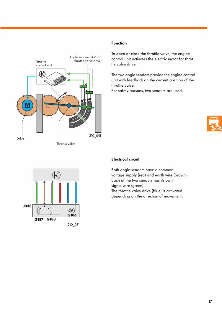
Function
To open or close the throttle valve, the engine control unit activates the electric motor for throt-tle valve drive.
The two angle senders provide the engine control unit with feedback on the current position of the throttle valve. For safety reasons, two senders are used.
Electrical circuit
Both angle senders have a commonvoltage supply (red) and earth wire (brown).Each of the two senders has its own signal wire (green). The throttle valve drive (blue) is activated depending on the direction of movement.
Drive
Throttle valve
Angle senders 1+2 forthrottle valve drive
J338
G187 G188G186
Enginecontrol unit
210_041
210_051

18
System components
Throttle valve drive G186
The throttle valve drive is an electric motor and is activated by the engine control unit. The throttle valve drive operates the throttle valve by means of a small gear. The throttle valve can be positioned in infinitely variable steps between the idling position and the full-throttle position.
Throttle valve position
- The lower mechanical stop
In this position, the throttle valve is closed. It is required for the basic adjustment of the throttle valve control unit.
- The lower electrical stop
is defined in the engine control unit and islocated just above the lower mechanical stop. During operation, the throttle valve is closed no further than the lower electrical stop. This prevents the throttle valve from intruding into the housing.
Throttle valve drive as shown at the housing cover of the
throttle valve control unit.
Throttle valve drive
Gear
Throttle valve
Return spring
Throttle valve
control unit housing
210_028
210_065
Engine control unit
210_023
19
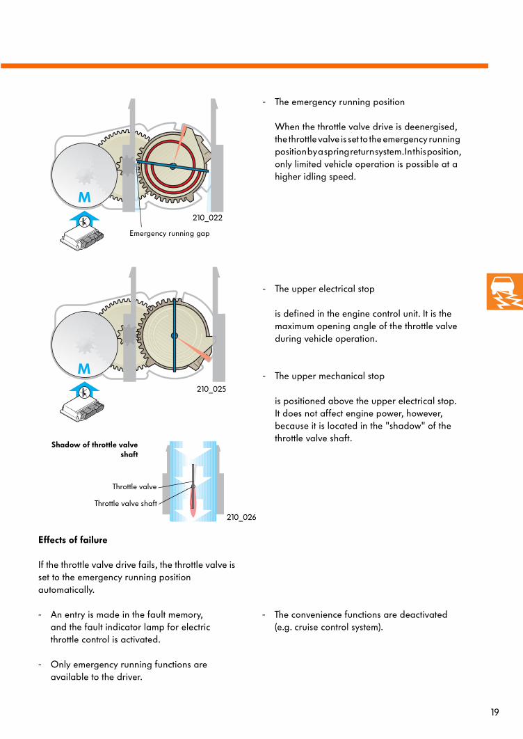
- The upper electrical stop
is defined in the engine control unit. It is the maximum opening angle of the throttle valve during vehicle operation.
- The upper mechanical stop
is positioned above the upper electrical stop. It does not affect engine power, however, because it is located in the "shadow" of the throttle valve shaft.
- The convenience functions are deactivated (e.g. cruise control system).
- The emergency running position
When the throttle valve drive is deenergised, the throttle valve is set to the emergency running position by a spring return system. In this position,only limited vehicle operation is possible at a higher idling speed.
Effects of failure
If the throttle valve drive fails, the throttle valve is set to the emergency running position automatically.
- An entry is made in the fault memory,and the fault indicator lamp for electric throttle control is activated.
- Only emergency running functions are available to the driver.
Shadow of throttle valveshaft
210_025
210_026
Throttle valve
Throttle valve shaft
Emergency running gap
210_022

20
System components
Angle sender 1 for throttle valve drive G187 and angle sender 2 for throttle valve drive G188
Design
The two senders are sliding contact potentiometers. The sliding contacts are located on the gear which is mounted on the throttle valve shaft. They scan the potentiometer strips in the housing cover.
Function
The resistances of the potentiometer strips - and therefore also the signal voltages transmitted to the engine control unit - vary with every change in the accelerator pedal position.
The curves of both potentiometers are inverse. This allows the engine control unit to differentiate between the two potentiometers and to execute test functions.
U
U
Throttle valve angle
Throttle valve angle
Printed circuit board withpotentiometer strips
Sliding contact Curve
Throttle valve shaft
Gear
Schematic diagram of sliding contact potentiometer
Angle senders 1 + 2
The angle of the throttle valve specified in percent in the measured value block. Hence, 0% corresponds to the lower electrical stop and 100% corresponds to the upper electrical stop.
G18
7G
188
210_027
210_036

21
Effects of signal failure
The engine control unit receives either an implau-sible signal, or no signal at all from an angle sender:
- An entry is made in the fault memory, and the fault warning lamp for electrical throttle con-trol is activated.
- Subsystems which influence torque (e.g. cruise control system or engine braking moment control) are deactivated.
- The load signal is utilised to monitor the residual angle sender.
- The accelerator pedal gives a normal response.
The engine control unit receives either an implau-sible signal, or no signal at all from the angle senders:
- An entry is made for both senders in the fault memory, and the fault indicator lamp for electric throttle control is activated.
- The throttle valve drive is deactivated.
- The engine runs at a higher idling speed of 1500 rpm only and no longer responds to the accelerator.

22
System components
Effects of failure
A defective fault indicator lamp has no effect on the function of the throttle control, however, it leads to an entry in the fault memory. Visual indication of additional faults in the sys-tem is no longer possible.
The fault indicator lamp
for Electronic Power Control K132 is located in the dash panel insert. It is a yellow lamp and bears the symbol "EPC“.
EPC stands for Electronic Power Control.
When does the lamp come on?
After turning on the ignition, the lamp comes on for 3 seconds. If there is no fault in the fault memory or if no fault is detected within this time period, the lamp goes off again.
If there is a fault in the system, the engine control unit activates the fault indicator lamp, and an entry is made in the fault memory.
Electrical circuit
The fault indicator lamp is activated directly by the engine control unit with an earth potential (brown).
K132
J285
210_049
210_040

23
Auxiliary signals
Brake light switch F and brake pedal switch F47
Signal utilisation
Both sensors are integrated in a component located on the brake pedal. The "brake pressed“ signal is utilisedtwice for the purpose of Electronic Power Control.
The "brake pressed“ signal
- causes the cruise control system to be shut down
- is utilised as a idling speed default if an accelerator position sender fails.
Brake pedal switch F47 serves as a backup information sender of the engine control unit.
Electrical circuit
Brake light switch F is open in the normal posi-tion and receives its voltage supply from terminal 30.Brake pedal switch F47 is closed in the normal position and receives its voltage supply from terminal 15.
F47F
Effects of signal failure
If one of the two sensors fails or if the input signals are found to be implausible, the engine control unit initiates the following actions:
- Convenience functions such as the cruise control system are deactivated.
- If an accelerator position sender is defective, too, then the engine speed is limited to an increased idling speed.
+15+30
210_047
210_042

24
System components
Clutch pedal switch F36
Signal utilisation
Through the signal from the clutch pedal switch, the engine control unit can recognise when the clutch pedal is pressed. The cruise control system and the load change functions will then be deactivated.
Effects of signal failure
The clutch pedal switch is not checked by the self-diagnosis function. There is no substitute function.
Electrical circuit
The switch is closed in the normal position and receives its voltage supply from terminal 15.
F36
210_043
210_048
25
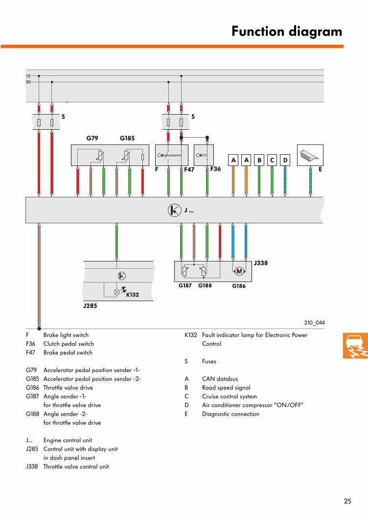
Function diagram
F Brake light switchF36 Clutch pedal switchF47 Brake pedal switch
G79 Accelerator pedal position sender -1- G185 Accelerator pedal position sender -2- G186 Throttle valve driveG187 Angle sender -1-
for throttle valve driveG188 Angle sender -2-
for throttle valve drive
J... Engine control unitJ285 Control unit with display unit
in dash panel insert J338 Throttle valve control unit
K132 Fault indicator lamp for Electronic Power Control
S Fuses
A CAN databus B Road speed signalC Cruise control systemD Air conditioner compressor "ON/OFF“E Diagnostic connection
J338
G187 G188 G186
J285
K132
G79 G185
F F47 F36A B
S S
E
J ...
A C
210_044
D

26
Self-diagnosis
Function 04 – Basic setting
The following functions can be executed with the Vehicle Diagnostic, Testing and Information System VAS 5051 in connection with Electronic Power Control:
- 02 – Interrogate fault memory- 03 – Actuator diagnosis- 04 – Basic setting- 05 – Erase fault memory- 06 – End of output- 08 – Read data block
210_102
Throttle valve control unit The basic setting procedure must performedafter the engine control unit, the throttle valve control unit or the complete engine has been replaced. At the same time, various positions of the throttle valve are activated and stored in the engine con-trol unit.
Please refer to the Workshop Manual!
Accelerator pedal module For several vehicles equipped with an automatic gearbox, it is necessary to perform the basic set-ting procedure after replacing the accelerator pedal module or the engine control unit, due the short travel of the accelerator pedal. At the same time, the kick-down position of the accelerator position sender is learned and stored in the engine control unit.
Please refer to the Workshop Manual!
27
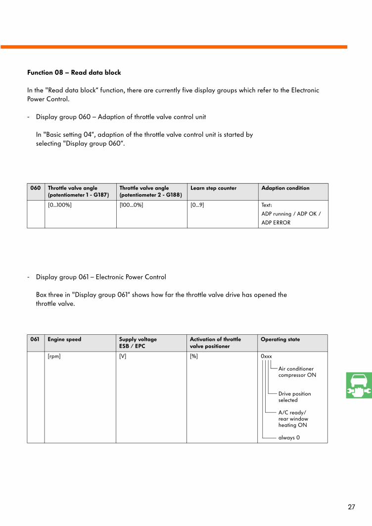
- Display group 061 – Electronic Power Control
Box three in "Display group 061“ shows how far the throttle valve drive has opened the throttle valve.
061 Engine speed Supply voltageESB / EPC
Activation of throttle valve positioner
Operating state
[rpm] [V] [%] 0xxx
Air conditioner compressor ON
Drive position selected
A/C ready/ rear windowheating ON
always 0
Function 08 – Read data block
In the "Read data block“ function, there are currently five display groups which refer to the Electronic Power Control.
- Display group 060 – Adaption of throttle valve control unit
In "Basic setting 04“, adaption of the throttle valve control unit is started by selecting "Display group 060“.
060 Throttle valve angle (potentiometer 1 - G187)
Throttle valve angle (potentiometer 2 - G188)
Learn step counter Adaption condition
[0...100%] [100...0%] [0...9] Text:
ADP running / ADP OK /
ADP ERROR

28
Self-diagnosis
- Display group 062 – Electronic Power Control
In "Display group 062“, the values of the two angle senders for throttle valve drive and the two accelerator position senders are displayed. These values are given as a percentage and refer to a voltage of 5 volts.
062 Throttle valve angle (potentiometer 1 - G187)
Throttle valve angle (potentiometer 2 - G188)
Accelerator pedal position sender -1- (-G79)
Accelerator pedal position sender -2- (-G185)
[0...100%] [100...0%] [0...98%] [0...49%]
- Display group 063 – Kick-down adaption
In "Basic setting 04“, adaption of the kick-down shift point is started by selecting "Display group 063“.
063 Throttle valve angle (potentiometer 1 - G187)
Throttle valve angle (potentiometer 2 - G188)
Accelerator pedal position
Operating states
[0...100%] [100...0%] Kick-down Text:ERROR / press / ADP running / ADP OK

29
- Display group 066 – Cruise control system
In "Display group 066“, you can find information regarding the cruise control system.
066 Road speed (actual) Switch position of brake, clutch and CCS
Specified road speed Switch position from CCS control panel switch
[kph] xxxx
Brake lightswitch
Brake pedalswitch
Clutchswitch
Cruise control system enabled
[kph] xxxx
CCS slide switch(latched)in OFF pos. yes/no
CCS slide switch(latched/not latched) in OFF positionyes/no
SET button pressedyes/no
CCS slide switch in RESposition yes/no

30
Test your knowledge
1. Name five torque demands which the engine control unit takes into account for the purpose of torque-oriented engine management.
2. What "tools“ does the engine management system have to influence engine torque?
3. Describe in note form the functions of the following components.
1. Accelerator pedal module:
2. Engine control unit:
3. Throttle valve drive:
4. Angle sender for throttle valve drive:
12
34
210_066

31
4. What points have to be observed when the throttle valve control unit is defective?
a) After replacing the throttle valve control unit, vehicle operation can be resumed immediately.
b) The throttle valve control unit can be repaired using a repair kit, and the accelerator position sender must be replaced after all repair work on the throttle valve control unit.
c) The throttle valve control unit must be replaced and the basic setting procedure must be performed.

32
Test your knowledgeSolutions:
1.)Start, catalytic converter heating, Traction Control System, engine braking control, speed limiting device, power limitation, cruise control system, air conditioning system, automatic gearbox (shift point)
2.)Throttle valve, charge pressure, injection time, cylinder suppression, ignition advance angle
3.)Accelerator pedal module: -determines - with its senders - the
momentary accelerator pedal position and transmits a corresponding signal tothe engine control unit.
Engine control unit: -receives the signals from the sensors,
processes them and then controls the actuators.
-checks the electrical throttle control function
Throttle valve drive: -positions the throttle valve
by means of an electric motor
Angle senders for throttle valve drive: -signal the position of the throttle valve to
the engine control unit
4.)c

33
Notes

34
Notes

35

For internal use only © VOLKSWAGEN AG, Wolfsburg
All rights reserved. Technical specifications subject to change without notice.
840.2810.29.20 Technical status: 05/99
This paper is produced from
non-chlorine-bleached pulp.
210


![KIA Function list V18 · Europe/General BESTA(TP) 2003 D 2.5 TCI ENGINE [Engine Control] √ √ √ √ Europe/General BESTA(TP) 2002 D 2.5 TCI ENGINE [Engine Control] √ √ √](https://img.dokumen.tips/doc/110x75/60c44e8d66090a68d26e2993/kia-function-list-v18-europegeneral-bestatp-2003-d-25-tci-engine-engine-control.jpg)