Embed Size (px)
Citation preview

Service Training
Self-study Programme 342
Radio Systems 2006
Design and Function

2
The self-study programme shows the design and function of new developments.The contents will not be updated.
For current testing, adjustment and repair instructions, refer to the relevant service literature.
Radio broadcasts are not just for entertainment. They are an important source of information in vehicles, in particular, that provide traffic news in addition to music and general information. New products are constantly required in the area of radio receivers in order to meet current and future requirements.
This self-study programme was compiled with the valuable help of Blaupunkt GmbH in Hildesheim. It should help you understand the audio technology used in Volkswagen vehicles as a supplement to self-study programme 147.
S342_055
NEW ImportantNote

3
Contents
Basics Radio reception in FM range . . . . . . . . . . . . . . . . . . . . . . . . . . . . . . . . . . . . . . . 4
Aerial properties . . . . . . . . . . . . . . . . . . . . . . . . . . . . . . . . . . . . . . . . . . . . . . . . 6
Audio CD (Audio Compact Disc). . . . . . . . . . . . . . . . . . . . . . . . . . . . . . . . . . . 12
Handling and care information for CDs and CD-ROMs . . . . . . . . . . . . . . . .14
Moving Picture Experts Group (MPEG) MP3 . . . . . . . . . . . . . . . . . . . . . . . . .15
Digital Audio Broadcasting (DAB) . . . . . . . . . . . . . . . . . . . . . . . . . . . . . . . . . .16
Radio SystemsR 100 radio . . . . . . . . . . . . . . . . . . . . . . . . . . . . . . . . . . . . . . . . . . . . . . . . . . . . .18
RCD 200 radio . . . . . . . . . . . . . . . . . . . . . . . . . . . . . . . . . . . . . . . . . . . . . . . . . 22
RCD 300 radio . . . . . . . . . . . . . . . . . . . . . . . . . . . . . . . . . . . . . . . . . . . . . . . . . 26
RCD 500 radio . . . . . . . . . . . . . . . . . . . . . . . . . . . . . . . . . . . . . . . . . . . . . . . . . 30
Sound Systems8-channel analogue amplifier . . . . . . . . . . . . . . . . . . . . . . . . . . . . . . . . . . . . . 34
10-channel digital amplifier . . . . . . . . . . . . . . . . . . . . . . . . . . . . . . . . . . . . . . . 36
12-channel digital amplifier . . . . . . . . . . . . . . . . . . . . . . . . . . . . . . . . . . . . . . . 38
10-channel DYNAUDIO high-end system . . . . . . . . . . . . . . . . . . . . . . . . . . . 40
Digital Signal Processing (DSP) . . . . . . . . . . . . . . . . . . . . . . . . . . . . . . . . . . . . 42
Loudspeaker locations . . . . . . . . . . . . . . . . . . . . . . . . . . . . . . . . . . . . . . . . . . . 44
Aerial systemsAerial systems for the Golf/Golf Plus . . . . . . . . . . . . . . . . . . . . . . . . . . . . . . . 46
Aerial systems for the Passat 2006 and Jetta 2006 . . . . . . . . . . . . . . . . . . . .51
Aerial connection systems . . . . . . . . . . . . . . . . . . . . . . . . . . . . . . . . . . . . . . . . 54
Glossary. . . . . . . . . . . . . . . . . . . . . . . . . . . . . . . . . . . . . . . . . . . . . . . . . . . . . .56
Test Yourself . . . . . . . . . . . . . . . . . . . . . . . . . . . . . . . . . . . . . . . . . . . . . . . . . . 58

4
Basics
You obtain the best reception when the broadcasting aerial can “see” the car aerial. The FM signals, which are transmitted by the transmitter with horizontal or vertical polarisation (depending on country), can be received best with an aerial that is mounted in a position that can be reached from all sides (the signals “see” the full length of the aerial).
Disadvantage: The range is lower than AM signals (MW, LW).
If you leave the range of the transmitter tower (the sound quality will become poor and there is sound interference), a new transmitter or a different frequency needs to be selected. On car radios with RDS (Radio Data System), an alternative frequency is searched for automatically.
FM waves cannot pass through hills, buildings and similar obstacles without being impaired. If the vehicle enters such an area, only poor or no reception is possible. This occurs in particular when you drive through mountains or between high-rise buildings. The range depends on the transmission power and the distance of the transmitter aerial from the ground. Transmitter aerials are therefore normally placed on towers, tall buildings or mountains.
S342_001
S342_002
S342_004
Radio reception in FM range
FM waves travel in straight lines. They are not reflected by the layers of the earth’s atmosphere and therefore do not follow the curve of the earth.

5
This can cause the direct signal to be deflected even in covered areas like, for example, built-up areas or mountains. This reflection could cause reception to be poor quality (reflection surface).
In some cases, the radio tuner picks up both the direct and also a reflected signal from the transmitter. This overlapping of the direct and reflected (delayed) signals can cause reception interference in the form of audible sound distortion in the speaker. Furthermore the time difference between the direct and indirect signal causes the reception quality to vary depending on the vehicle position.
The fluctuations of the reception level occur with VHF reception with relatively small changes of location. The vehicle shown in the diagram is equipped with two aerials at a distance of approx. 1 m from each other. In the diagram, you can see that the front aerial has a very high receiving level and the rear one a very low one even though the distance between the two aerials is relatively small compared with the transmitter distance.
S342_003
Deflected indirect signals
S342_005
FM waves are reflected by building, hills etc. Reception from several directions results (multipath).
Leve
l
Path in m

6
Basics
Aerial properties
Reception properties of a standard FM aerial
The blue area indicates the direction-related reception sensitivity of the aerial. Here you can clearly see that the aerial is sensitive to signals from all directions. Direct and reflected signals are thus received with the same strength. This aerial configuration contributes to interference from multipath reception.
S342_006
Technical suppression of multipath interference
As multipath interference is unpleasant particularly in the higher audible frequency range, a technical solution to reduce interference is needed.
One possibility for reduction is the “highcut method”. However the disadvantage of this is that “cutting” the high frequencies has a negative effect on the sound in this range.
Interference-free audio signal
S342_007
S342_008
The audio amplifier in the car radio amplifies all frequencies that can be heard by the human ear to a level appropriate to the human sensory range.
Frequency
Frequency
Time
Receiving level
Overhead view of aerial
Direct FM signal
Reflected FM signal

7
Highcut
Interference from signal-changing disturbing pulses
Disturbing pulse in signal
Disturbing pulse after highcut
If interference occurs in the upper frequency range due to multipath reception, it will be suppressed by the highcut function in the FM tuner of the car radio.
Highcut cuts off high frequencies if interference occurs.
S342_009
S342_010
Frequency
Time
Receiving level
Frequency
Disturbing pulses

8
Basics
Phase diversity
One better method of reducing interference is the phase diversity aerial principle. The phase diversity is also more technically complex than, for example, highcut as 2 tuners and 2 aerials are needed.
Phase diversity works with two different reception modes, the “interference-free signal” reception mode and the “interference signal” reception mode.
This reception type basically works in the same way as a directional aerial. During operation, these aerials are continuously “turned” virtually in the direction of the signal source.
Turning the aerial is, of course, only simulated by the digital signal processing. The aerial is not actually rotated. However, the effect is exactly the same. The aim is to provide the direct signal with as much aerial surface as possible and the reflected signal with as little as possible.
S342_011

9
S342_012
Direct signal
Reflected signal
Radio transmitter
Single-tuner receiver
Dual-tuner phase diversity
Distance from radio transmitter
S342_013
Directional aerialThe blue area indicates the direction-dependent reception sensitivity of the aerial system and the evaluation electronics. You can clearly see here that the system for the direct signal is particularly sensitive while it is more insensitive to the reflected signal. Multipath interference is suppressed here to a great extent.Less highcut is therefore also used, which leads to a considerable sound improvement. Furthermore the system is more sensitive in the direction of the direct signal. As a result, the reception is improved considerably and thus more stereo reception and less silent pauses are noticed.
Signal strength
The signal strength of a conventional single-tuner receiver is considerably lower compared with a two-tuner phase diversity receiver depending on the distance of the radio transmitter.
Receiving property of diversity aerial system with two FM aerials

10
In “interference-free” reception mode, the electronics in the radio constantly check which aerial receives the strongest signal and select the stronger one for the input signal. The demodulator converts the HF aerial signals into inaudible signals and forwards them to the radio data system.
The second tuner constantly searches the whole frequency band for better reception frequencies for the selected station. If a better signal is found, this tuner switches to reception and the other switches to scanning mode in the background. This avoids the RDS-AF test pauses as experienced with single-tuner systems.
This is called the background mode (collect data).
Basics
Reception aerial I
Reception aerial II Demodulator II
Demodulator I Radio Data System I
Radio Data System IITuner II
Tuner I
Signal converter
S342_029
“Interference-free signal” reception mode

11
In “interference signal” reception mode, the signals from both aerials are digitised in an intermediate frequency analogue/digital converter and processed using an adaptive algorithm. This process removes the interference signals by forming a new, directed aerial signal.The aerial power is also improved by up to 3 dB.
The second demodulator and the second radio data system remain unused in the background in this mode as both aerials are required to receive the selected station.
This mode is called phase diversity.
“Interference signal” reception mode
Reception aerial I
Reception aerial II Tuner II
Tuner I Radio Data System I
Signal converter
Demodulator II
Demodulator I
S342_030
Radio Data System II

12
Basics
The analogue music signal is converted to a digital signal by an analogue/digital converter. The aim of digitalisation is to emulate the analogue signal digitally and without interference in as smaller steps as possible. The higher the resolution (e.g. 8 - 16 - 32 - 64 bit) of the A/D converter, the more authentic the sound result (emulation of the analogue signal).
S342_014
Analogue signal Digital signal
Analogue/digital converter
Time
S342_056
To obtain a suitable signal from the digital signals for playback via the speakers, an analogue signal needs to be formed again in the CD player using a D/A converter.
Digital/analogue converter
Audio CD (Audio Compact Disk)
Audio CDs, which started to become established among home users in 1982, are increasingly being used in cars and are becoming more popular than compact cassettes.
Audio CDs are optical mass storage media for the digital storage of music.

13
The CD mainly consists of a transparent carrier material (substrate), which is moulded by means of compression injection. The top side of this carrier contains the digital information in the form of microscopic pits and lands that are arranged in a single long, spiral track (around 5 km in total).
This surface containing information is covered with a thin aluminium film and sprayed with an acrylic layer. A label can then be applied or printed on. The information is scanned with a laser through the carrier layer without contact and thus free of wear.
S342_015
Laser diode Semi-transparent mirror
Photo diode
Land
Pit
Substrate

14
Basics
Only touch CDs by the sides.
Avoid getting finger prints on the CD.
If a CD becomes dirty, never wipe the CD with circular motions. Instead wipe with a soft lint-free cloth from the inside to the outside.
Also handle CDs carefully both from the underside and from the top. Do not write on the CD and do not affix labels.
All CDs should be handled carefully and always be stored in a protective case. Also keep CDs away from heat and direct sunlight.
Handling and care information for CDs and CD-ROMs
S342_060
S342_061
S342_063
S342_062
S342_064

15
MP3 is a file format for audio compression.Like other formats, MP3 is based on the fact that human perception is limited. The number of sounds that people perceive is reduced, for example, due to their frequency or volume.As this process involves losses, the original output signal cannot be reproduced completely.
The losses depend greatly on the data rate. At around 128 kBit/s, the differences from the original are hardly noticeable if music with a low dynamic scope is involved (pop music, synthesizer, techno). For example, with guitar and violin music, you will soon notice annoying differences to the original at 128 kBit/s, average data rates of 192 kBit/s or higher are recommended for this style of music.
S342_037
Non-audible frequencies — the range perceivable by adults is from 20 Hz to 18 kHz — are cut off in the data.
S342_058
Frequency
Time
Moving Picture Experts Group (MPEG) MP3

16
Basics
Digital Audio Broadcasting (DAB)
The Digital Audio Broadcasting system (DAB) differs considerably from previous analogue data transfer systems. In DAB, the receiver does not only receive an audio signal (music, language), but also additional data signals (services) with information on travel, schedule, music, weather, etc. If the radio is equipped with a suitable display, graphics, for example, maps or animations, can also be displayed.
The DAB frequency range (47 MHz to 1468 MHz) is divided up into several channels each with a bandwidth of 1.536 MHz. The basic signals for audio and service data are digitised in the transmitter, compressed (MPEG), encoded separately and chopped up into time sections. Then all basic signals are combined in a frequency mixer and sent to the respective channel in digital form. That is the content of a station in the simplest form (e.g. NDR 2).
That means
● Separation into programmes ● Separation according to audio tracks and service● Reassemble signal in order ● Decode signal ● D/A conversion
Regions with DAB in Germany
S342_031

17
Due to the data reduction, it is generally the case that several stations find space in the bandwidth of a channel with their respective audio tracks and services. All of these programs combined in a channel are called an ensemble (e.g. North I). In the receiver, the DAB radio, the signals are processed in reverse order.
The DAB transmission accesses the conventional terrestrial transmission systems. Due to the low susceptibility to interference of digital signals, the transmitter can work with a radiated power of approx. 1 kW. A typical VHF transmitter has a transmission power of 10 to 100 kW.
S342_057
North I
NDR 2 FFN NDR 3
NDR 2audio
NDR TMC
NDR data
FFN audio
FFNdata
NDR 3 audio
DAB ensemble

18
Radio Systems
R 100 radio
The R 100 radio is available for the Volkswagen Golf 2004, Touran and in other models for bulk customers, e.g. fleet operators. This radio unit has the following functions:
- Single-tuner- Two output stage with 20 Watt output, 2 speaker
channels can be connected- RDS FM/AM Europa radio (VHF/MW)- Control for an external 6-CD changer- Mute mode for telephone hands-free system- Speed-dependant volume control (GALA)- Self-diagnosis incl. loudspeaker diagnosis- Transport mode (reduction of the current
requirement during transport and rest times)
On/off switchPressing the tuning knob switches the radio on and off.The last station tuned and last volume level set will be selected.
Station buttons 1-3Pressing the station buttons calls up the stored stations.
You can store stations manually(once a station has been tuned, hold down the station button until you hear a signal) or automatically (hold down the AS button until STORE appears in the display).
TP buttonWhen the TP option is switched on, only stations that broadcast regular traffic reports will be offered (traffic program stations) during automatic station searches. If a traffic program station is tuned, an incoming traffic report will be played in the current radio mode.
CD buttonSelect CD changer mode Display

19
S342_016
FM buttonPress to select the VHF (frequency modulation) frequency range.
AM buttonPress to select the MW (amplitude modulation) frequency range.
Tuning knob- For manual station tuning- For sound settings
(BASS, TREBLE), BALANCE and GALA - For the SCAN function
AS button (auto store)If you press the AS button, the six stations with the greatest field strength are stored automatically and spread across the station buttons according to their field strength.
Station buttons 4-6
BAL buttonPress this button to open the menu for setting the balance.Turn the tuner knob to change the volume balance on the left and right.
Sound settingsPressing this button opens the menu for adjusting the bass (display: BASS).Press it again to open the menu for adjusting the treble (display: TREB).Turn the tuner knob to the desired tone level.
Station search buttons
Please follow the respective operating manual when using the radio.

20
Radio Systems
Legend
A BatteryR RadioR11 AerialR20 Front left treble loudspeakerR21 Front left bass loudspeakerR22 Front right treble loudspeakerR23 Front right bass loudspeakerR41 CD changerR108 Left aerial moduleS Fuse
Input signal
Output signal
Voltage supply (plus)Earth (minus)
CAN data bus line
Functional diagram for R 100 radio in Volkswagen Golf/Touran

21
CAN data bus
S342_022

22
Radio Systems
RCD 200 radio
- Single-tuner- Four output stages with 20 Watt output, 2 or 4
speaker channels can be connected- RDS FM/AM Europa radio (VHF/MW)- Integrated single CD drive- Control for an external 6-CD changer- Convenience code- Mute mode for telephone hands-free system- Speed-dependant volume control (GALA)- Self-diagnosis incl. loudspeaker diagnosis- Transport mode (reduction of the current
requirement during transport and rest times)
On/off switchPressing the tuning knob switches the radio on and off. The last station tuned and last volume level set will be selected.
Station buttons 1-3Pressing the station buttons calls up the stored stations.
You can store stations manually (once a station has been tuned, hold down the station button until you hear a signal) or automatically (hold down the AS button until STORE appears in the display).
AS button (auto store)If you press the AS button, the six stations with the greatest field strength are stored automatically and spread across the station buttons according to their field strength.
FM buttonPress to select the VHF (frequency modulation) frequency range.
Balance/fader buttonPressing the B/F button opens the menu for setting the balance (display: BAL).Press it again to open the menu for adjusting the volume distribution between the front and rear (fader, display: FAD).Turn the tuner knob to the desired setting.
The output stages for the rear speakers are only active if speakers are actually connected. The fader functions will only become active when they are connected.

23
S342_017
AM buttonPress to select the MW (amplitude modulation) frequency range.
CD buttonPress this button to switch to CD mode or CD changer mode.
TP buttonWhen the TP option is switched on, only the stations that broadcast regular traffic reports will be offered (traffic program stations) during automatic station searches.
If a traffic program station is tuned, an incoming traffic report will be played in the current radio mode.
Tuning knob- For manual station tuning- For sound settings
(BASS, TREBLE), BALANCE and GALA - For the SCAN function- For track selection in CD mode
Station buttons 4-6
BAS tone buttonPressing the BAS button opens the menu for setting the bass (display: BASS).Turn the tuner knob to the desired tone level.
Mix buttonThe tracks on the current CD will be played in a random order.
TRE tone buttonPressing the TRE button opens the menu for setting the treble (display: TRE).Turn the tuner knob to the desired tone level.

24
Radio Systems
Legend
A BatteryR RadioR11 AerialR15 Rear left bass loudspeaker
(Polo: treble and bass loudspeakers)(Fox: wide band loudspeaker)
R17 Rear right bass loudspeaker(Polo: treble and bass loudspeakers)(Fox: wide band loudspeaker)
R21 Front left bass loudspeaker(treble and bass loudspeaker)
R23 Front right bass loudspeaker(treble and bass loudspeakers)
R24 Aerial amplifierR41 CD changerS Fuse
Input signal
Output signal
Voltage supply (plus)Earth (minus)
CAN data bus line
CAN data bus
Functional diagram for RCD 200 radio in Volkswagen Fox/Polo 2006

25
S342_023

26
Radio Systems
RCD 300 radio
The RCD 300 radio is available as the standard radio system for private customers.It has the following functions:
- FM dual-tuner diversity - Four output stages with 20 Watt output, 2 or
4 speaker channels can be connected- RDS FM/AM Europa radio (VHF/MW)- Stored stations with RDS name shown in display- Control via multifunction steering wheel (MFW)
and multifunction display (MFD)- Integrated single CD drive- Control for an external 6-CD changer- Convenience code- Mute mode for telephone hands-free system- Speed-dependant volume control (GALA)- Self-diagnosis incl. loudspeaker diagnosis- Transport mode- Driving school version (optional)
On/off switchPressing the tuning knob switches the radio on and off. The last station tuned and last volume level set will be selected.
Multifunction buttonsThe functions of the multifunction buttons depend on the respective operating mode.The current assignment of the multifunction buttons is shown in the display.
CD buttonPress this button to switch to CD or CD changer mode.
TP buttonWhen the TP option is switched on, only the stations that broadcast regular traffic reports will be offered (traffic program stations) during automatic station searches. If a traffic program station is tuned, an incoming traffic report will be played in the current radio mode.
Mix buttonThe tracks on the current CD will be played in a random order.

27
S342_018
FM buttonPress to select the VHF (frequency modulation) frequency range.
AM buttonPress to select the MW (amplitude modulation) frequency range.
AS button (auto store)If you press the AS button, the six stations with the greatest field strength are tuned automatically and stored in the second memory level (AM 2/FM 2) according to their field strength.
Tuning knob- For manual station tuning- For the SCAN function- For track selection in CD mode
Multifunction buttons
Menu button for sound settings and setupSOUND: The menus for setting the tone (TREBLE, BASS) and volume distribution (BALANCE, FADER) are called up with the multifunction buttons.You make the settings with the tuning knob.SETUP: The SETUP menu is called up from the SOUND menu. The GALA, ON-VOL and RDS-REG settings are made with the tuning knob and the search buttons.
Station search buttonsRadio: Press briefly to search for stations automatically. CD mode: Press briefly to select the tracks on the current CD; hold down to listen to a CD track in rewind/fast forward mode.Menu functions:Pressing switches the menu functions on and off.

28
Radio Systems
Legend
A BatteryR RadioR11 Aerial (AM/FM)R14 Rear left treble loudspeakerR15 Rear left bass loudspeakerR16 Rear right treble loudspeakerR17 Rear right bass loudspeakerR20 Front left treble loudspeakerR21 Front left bass loudspeakerR22 Front right treble loudspeakerR23 Front right bass loudspeakerR41 CD changerR93 Radio aerial 2 (FM)R108 Left aerial moduleR109 Right aerial moduleS Fuse
Input signal
Output signal
Voltage supply (plus)Earth (minus)
CAN data bus line
CAN data bus
Functional diagram for radio RCD 300 in Volkswagen Touran

29
S342_024

30
RCD 500 radio
The top of the range radio is the RCD 500 with the following functions:
- FM dual-tuner diversity - Four output stages with 20 Watt output, 4 speaker
channels connected- RDS FM/AM Europa radio (VHF/MW)- Stored stations with RDS name shown in display- Control via MFW and MFD- Integrated 6-CD changer - Control for an external 6-CD changer - Mute mode for telephone hands-free system- Speed-dependant volume control (GALA)- Traffic Information Message (TIM)- Convenience code- Self-diagnosis incl. loudspeaker diagnosis- Transport mode- Optional external sound amplifier can be
connected (output stage reduction by 14 dB)
Radio Systems
On/off switchPressing the tuning knob switches the radio on and off. The last station tuned and last volume level set will be selected.
Multifunction buttons
Traffic Information Messages (TIM)The TIM button allows you playback recorded traffic reports. After entering up to two different TIM times in the SETUP menu, you will be able to record traffic reports at a specific time even when the radio is turned off.
TP buttonWhen the TP option is switched on, only the stations that broadcast regular traffic reports will be offered (traffic program stations) during automatic station searches. If a traffic program station is tuned, an incoming traffic report will be played in the current radio mode.
Mix button (random playback)The tracks on the current CD will be played in a random order.

31
S342_019
FM buttonPress to select the VHF (frequency modulation) frequency range.
AM buttonPress to select the MW (amplitude modulation) frequency range.
AS button (auto store)If you press the AS button, the six stations with the greatest field strength are tuned automatically and stored in the second memory level (AM 2/FM 2) according to their field strength.
Tuning knob- For manual station tuning- For the SCAN function- For track selection in CD mode
Multifunction buttonsThe functions of the multifunction buttons depend on the respective operating mode.The current assignment of the multifunction buttons is shown in the display.
Menu button for sound settings and setupSOUND: The menus for setting the tone (TREBLE, BASS) and
up with the multifunction buttons.You make the settings with the tuning knob.SETUP: The SETUP menu is called up from the SOUND menu. The GALA, ON-VOL and RDS-REG settings are made with the tuning knob and the search buttons.
Station search buttonsRadio: Press briefly to search for stations automatically.CD mode: Press briefly to select the tracks on the current CD; hold down to listen to a CD track in rewind/fast forward mode.Menu functions:Pressing switches the menu functions on and off.
volume distribution (BALANCE, FADER) are called

32
Legend
A BatteryJ519 Onboard supply control unitR RadioR11 AerialR14 Rear left treble loudspeakerR15 Rear left bass loudspeakerR16 Rear right treble loudspeakerR17 Rear right bass loudspeakerR20 Front left treble loudspeakerR21 Front left bass loudspeakerR22 Front right treble loudspeakerR23 Front right bass loudspeakerR41 CD changerR93 Radio aerial 2R108 Left aerial moduleR109 Right aerial moduleR177 Amplitude modulation frequency filter (AM)R178 Frequency modulation frequency filter (FM)
in the negative wireR179 Frequency modulation frequency filter (FM)
in the positive wireS FuseZ1 Heated rear window
Radio Systems
Input signal
Output signal
Voltage supply (plus)Earth (minus)
CAN data bus line
Functional diagram for radio RCD 500 in Volkswagen Golf
CAN data bus

33
S342_025

34
Sound Systems
The use of external multi-channel amplifier improves the sound quality inside the car in several ways:
● Improved sound dynamics● Car-specific sound configuration ● Greater frequency ranges● Better sound distribution● Authentic sound (concert hall quality)
An amplifier system is made up of the amplifier along with the treble, mid-range and bass loudspeakers.
The external amplifier generates the signal with the corresponding frequency response for the individual speaker outputs and uses 8-channel analogue technology. It has eight internal output stages that control ten speakers via ten outputs. The outputs for the rear bass and treble speakers are combined via an internal frequency filter.
The signal inputs on the amplifier are controlled via the speaker outputs on the radio unit or radio-navigation unit. The radio/RNS unit needs to be coded to “Sound” so that the level of the output channels is reduced by 14 dB.
Self-diagnosis is carried out via the CAN data bus.
The 8-channel analogue sound system is available for the Passat 2006, Golf 2004, Jetta 2006 and Touran.
Legend
A BatteryR RadioR12 AmplifierR14 Rear left treble loudspeakerR15 Rear left bass loudspeakerR16 Rear right treble loudspeakerR17 Rear right bass loudspeaker
8-channel analogue amplifier
CAN data bus

35
R20 Front left treble loudspeakerR21 Front left bass loudspeakerR22 Front right treble loudspeakerR23 Front right bass loudspeakerR103 Front left mid-range loudspeakerR104 Front right mid-range loudspeakerS Fuse
Input signal
Output signal
Voltage supply (plus)Earth (minus)
CAN data bus line
S342_026

36
Sound Systems
The 10-channel digital amplifier uses digital signal processing and supplies the connected speakers with an output power of 600 Watts. A special switched-mode power supply in the amplifier ensures that even the top pulse overshoots are not cut off and therefore no signals for the audible frequencies are filtered.
The signal inputs on the amplifier are controlled via the speaker outputs on the radio unit or radio-navigation unit and digitally via the CAN data bus.
Self-diagnosis is carried out via the CAN data bus.
The 10-channel digital amplifier is available for the Passat 2006 with DYNAUDIO loudspeakers.
Amplifier output power:
Bass loudspeaker: 4 x 120 WattMid-range loudspeaker:2 x 30 WattTreble loudspeaker: 4 x 15 Watt
10-channel digital amplifier
Legend
A BatteryR RadioR12 AmplifierR14 Rear left treble loudspeakerR15 Rear left bass loudspeakerR16 Rear right treble loudspeakerR17 Rear right bass loudspeaker
CAN data bus

37
R20 Front left treble loudspeakerR21 Front left bass loudspeakerR22 Front right treble loudspeakerR23 Front right bass loudspeakerR103 Front left mid-range loudspeakerR104 Front right mid-range loudspeakerS Fuse
S342_053
Input signal
Output signal
Voltage supply (plus)Earth (minus)
CAN data bus line

38
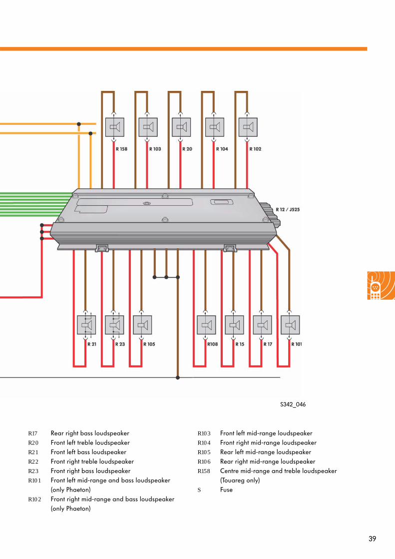
Sound Systems
The 12-channel digital amplifier is used in the Volkswagen Touareg and Volkswagen Phaeton. It has a total of 12 outputs, to which four bass, four mid-range, one mid-range and treble and two treble loudspeakers are connected in the Touareg and four bass, four mid-range, two mid-range and treble and two treble loudspeakers are connected in the Phaeton. One channel is therefore free in the Touareg.
The 12-channel digital amplifier is controlled with the radio or radio-navigation unit in the Touareg digitally via the CAN data bus.
In the Phaeton, the 12-channel digital amplifier is controlled via the front information display and operating unit control unit and the CAN data bus.
Self-diagnosis is carried out via the CAN data bus.
12-channel digital amplifier
Legend
A BatteryJ523 Front information display and operating unit
control unit (only Phaeton)J525 Digital sound package control unit
(only Phaeton)R RadioR12 AmplifierR15 Rear left bass loudspeaker
Input signal
Output signal
Voltage supply (plus)Earth (minus)
CAN data bus line
CAN data bus
39
R17 Rear right bass loudspeakerR20 Front left treble loudspeakerR21 Front left bass loudspeakerR22 Front right treble loudspeakerR23 Front right bass loudspeakerR101 Front left mid-range and bass loudspeaker
(only Phaeton)R102 Front right mid-range and bass loudspeaker
(only Phaeton)
S342_046
R103 Front left mid-range loudspeakerR104 Front right mid-range loudspeakerR105 Rear left mid-range loudspeakerR106 Rear right mid-range loudspeakerR158 Centre mid-range and treble loudspeaker
(Touareg only)S Fuse

40
Sound Systems
Due to the different locations of the speakers and the different materials (e.g. soft seats and hard windows), configuring an ideal sound inside a vehicle is very difficult.
The careful positioning of ten speakers allows balanced sound distribution in the whole interior.
The continuous output of the DYNAUDIO 10-channel high-end systems is 600 W. This is distributed in different ways between the individual outputs as, for example, the treble speakers have the highest wattage.
10-channel DYNAUDIO high-end system
S342_038

41
Speaker concept
To obtain a deep, but also precise bass sound, a total of four bass speakers have been anchored with DYNAUDIO’s MSP membranes in the door construction with low-resonance.For an open and clear mid-range two extra large mid-range speakers with textile cones (80 mm) are mounted in the front doors.
Two 20 cm bass speakers are fitted in the front doors and two 16.8 cm bass speakers in the rear.
Filigree treble information is a basic requirement for authentic music playback. Therefore two 48 mm textile treble speakers share the work with the high frequencies in the front. As high frequencies tend to travel in one physical direction, two 40 mm variants at the rear of the vehicle support this important frequency range. The weight advantage (aluminium instead of copper) is used in favour of a longer coil. This allows linear dynamics even at the top levels. The dome in the treble speakers is made from textile instead of plastic.
S342_039
S342_040
The DYNAUDIO brand is a guarantee of high-quality sound. DYNAUDIO uses the lightest materials, i.e. the surface emitting the sound is enlarged three to four times while keeping the same speaker weight. The effectiveness is thus increased three to four times. Also the whole area of the single-piece diaphragm is part of the polar pattern. The coil design and magnet construction leads to linear pattern across the whole frequency range resulting in perfect diffusion and better thermal loading capacity (heat discharge).

42
Sound Systems
Digital Signal Processing (DSP)
S342_047
Amplifier stage
The incoming signal from the radio is amplified in the amplifier stage and sent to the outputs.
Filter stages
The sound is processed in the filter stages. The signal amplitudes are reduced or amplified in certain frequency ranges in up to five downstream filter stages.
Distortion limiter
Distortion can occur in the sound processing. This is reduced in the distortion limiter, which also keeps the harmonic distortion low.
DSP technology means that the sound curves can be programmed individually in the amplifier for each speaker output. There are therefore special characteristic curves for each type of vehicle as the signal from each audio channel is prepared specifically.The aim of vehicle-specific sound configuration is to generate as authentic a sound as possible on a virtual stage in front of the occupants.
Amplifier
Distortion limiter
Filter stages Time-delay element
Signal input
Signal output
Amplifier stage
Time-delay element
The signals for the rear speakers are delayed in the time-delay element by several milliseconds so that concert hall characteristics are created inside the vehicle.
* DDL - Dynamic Distortion Limiter

43
S342_048
Sound curve graph
Actual curve
Ideal vehicle-specific sound curveCountermeasure in amplifier (amplify)
Target curve of individual loudspeaker
Amplifier countermeasure (reduce)
Bass loudspeaker curve Mid-range loudspeaker curve Treble loudspeaker curve
Frequency Hz
Amplification dB
The actual sound curve (blue) is dependent on the interior characteristics. It is raised in the bass area and is thus configured for the human ear.
The sound delay of the rear speakers is maintained by the time-delay element regardless of the fader setting.
Sound curve
The sound curve is specially configured for the vehicle interior and stored in a characteristic curve in the amplifier. In this way, frequency ranges where there is a risk of interior components resonating are reduced and other frequencies, which could be weakened by sound absorbing components, are increased.

44
Sound Systems
Speaker locations
S342_049
DLT Ø 46 mmin mirror triangle
MRS Ø 80 mm on AC
BS Ø 200 mmon AC
TS Ø 46 mmin panel
BS Ø 168 mmon AC
Passat 2006 basic speaker system
Golf 2004 loudspeaker system
DLT Ø 46 mmin mirror triangle
MRS Ø 114 mm in door panel
BS Ø 200 mmon AC
TS Ø 46 mmin panel
BS Ø 168 mmon AC
3-wayfrequency filter
Legend
DTL Domed treble loudspeakerMRS Mid-range loudspeaker
BS Bass loudspeakerTS Treble loudspeakerAC Assembly carrier
Legend
DTL Domed treble loudspeakerMRS Mid-range loudspeaker
BS Bass loudspeakerTS Treble loudspeakerAC Assembly carrier
Amplifier
Amplifier
S342_050

45
S342_051
Touareg speaker system
DLT Ø 46 mmin mirror triangle
MRS Ø 60 mm in door panel
BS Ø 220 mmon AC
MRS Ø 60 mm in panel
BS Ø 220 mmon AC
Legend
DTL Domed treble loudspeakerMRS Mid-range speaker
BS Bass speakerTS Treble speakerAC Assembly carrier
Amplifier
MRS Ø 60mm
S342_052
Phaeton speaker system
DLT Ø 46 mmin mirror triangle
MRS Ø 60 mm in door panel
BS Ø 220 mmon AC
MRS Ø 60 mm in panel
BS Ø 220 mmon AC
Amplifier
Legend
DTL Domed treble loudspeakerMRS Mid-range loudspeaker
BS Bass loudspeakerTS Treble loudspeakerAC Assembly carrier

46
Aerial Systems
If the Golf or Golf Plus is ordered without a radio/radio preparation, there will not be an aerial connection on the left of the rear windscreen.The basic aerial structure in the rear windscreen is always included and identical in specific models.The structure is made up of horizontal and vertical reception wires. The horizontal wires are used to receive horizontally polarised signals and the vertical wires receive vertically polarised signals.
There is a hole for the aerial in the roof that is sealed with a plug. The plug is shaped like an aerial (shark fin).It can be replaced with a roof aerial.
Aerial systems for the Golf/Golf Plus
S342_033
Vehicles without radio and radio preparation
Plug for sealing the aerial hole
Connecting cable for 12-volt rear window heating element Negative connecting cable for 12-volt rear window heating element
The aerial wiring is missing in this setup and needs to be fitted if a radio is retrofitted.
Decoupling point/connecting point for aerial (as high as possible for better reception)
Horizontal reception wires Vertical reception wires

47
Cars that are ordered with the R 100 and RCD 200 (radios with single-tuner concept) radios come with a mast-type roof aerial. The rear windscreen is identical to that on the vehicles without a radio.AM and FM rejector circuits are not needed due to the mast-type aerial being electrically isolated from the heated rear windscreen. The reception is just as good as a windscreen aerial.
Vehicles with single-tuner radios without telephone, navigation, remote start
S342_032
Roof aerial for AM/FM radio reception
Connecting cable for 12-volt rear window heating element
Negative connecting cable for 12-volt rear window heating element
R 100 radio
Only one rear windscreen version with two aerial connection litz wires is available as a customer service replacement.
B
Connector colour codes (see page 52)

48
The RCD 300 and RCD 500 radio systems require two aerials for their internal dual-tuner diversity receiver. They use a rear windscreen aerial and a mast-type aerial on the roof as standard. The rear windscreen aerial needs at least one connecting wire to be connected to the aerial structure. If there are two connecting litz wires on the rear windscreen, the aerial will be connected on the left.
Aerial Systems
Vehicles with dual-tuner radios without telephone, remote start and navigation
S342_035
Roof aerial for AM/FM radio reception
FM impedance transformer (aerial amplifier)
FM rejector circuit + FM rejector circuit -
RCD 300 radio
RCD 500 radio
Connecting cable for 12-volt rear window heating element
Negative connecting cable for 12-volt rear window heating element
Windscreen aerial for FM radio reception
B
B
I
I

49
As the roof aerial is needed for telephone, remote start and navigation, radio signals need to be received via the rear windscreen aerial. A roof aerial is needed to receive the satellite signals for navigation, the telephone signals and the signal to activate the auxiliary heating (remote start).
The signals are decoupled via a filter switch if the car is equipped with a telephone and remote start.
Vehicles with single-tuner radios with telephone, remote start and/or navigation
S342_034
Roof aerial
Connecting cable for 12-volt rear window heating element
Negative connecting cable for 12-volt rear window heating element
AM/FM impedance transformer (aerial amplifier)
AM rejector circuit
FM rejector circuit + FM rejector circuit -
RCD 200 radio
R 100 radio
RNS 300 radio
Remote start
Telephone reception
B
B
B
C
I D
Filter switch
Windscreen aerial for AM/FM radio reception

50
The GPS satellite signals for navigation and the telephone signals for calls and activating the auxiliary heating are received via the roof aerial.
Two aerials, located in the rear windscreen, are used to receive the radio signals for the two-tuner diversity receiver.
Aerial Systems
S342_036
Roof aerial
FM impedance transformer (aerial amplifier)
FM rejector circuit + FM rejector circuit -
RCD 300 radio
RCD 500 radio
RNS-MFD radio
Start auxiliary heating C
Connecting cable for 12-volt rear window heating element
Negative connecting cable for 12-volt rear window heating element
AM rejector circuit
AM/FM impedance transformer (aerial amplifier)
Filter switch
I D
B
B
B
I
I
I
Vehicles with diversity and telephone, remote start and/or navigation

51
Rear windscreen
Aerial systems for the Passat 2006 and Jetta 2006
S342_041
There are three types of rear windscreen:
● Rear windscreen without rejector circuits and module mountings● Rear windscreen with rejector circuits without GPS and GSM modules● Rear windscreen with rejector circuits with GPS and GSM modules
The contact surfaces for the aerial modules are present on each of the windscreens and the modules can be retrofitted. The wiring is only provided for the ordered equipment version — wires have to be laid when retrofitting.
FM 2 aerial FM 1 aerial
Aerial module mounting
AM aerial DAB aerialRemote start aerial
GSM module mounting
GPS module mounting
Heating wires
Windscreen layout
This view of the rear windscreen is from inside the car.

52
Aerial Systems
Vehicles with single-tuner radios and telephone without remote start and/or navigation
S342_042
S342_043
Vehicles with single-tuner radios and telephone, remote start and navigation
Variants
As the mountings for the GSM and GPS modules are simply fastenings and are electrically isolated from the rear windscreen, the installation of the module does not depend on the radio and aerial concept and is only shown as an example in the following diagrams.
GSM aerial module
AM/FM aerial module
RCD200 radio
AM/FM aerial module mounting
GSM aerial module mounting
Mobile phone
Rear windscreen
GSM aerial module
AM/FM aerial moduleand remote start
RNS 300 radio
AM/FM aerial module and remote start mounting
GSM aerialmodule mounting
Mobile phone
Rear windscreen
Remote start receiver
GPS aerial module
D
DB
B
D
D
C
CB
I
K B
GPS aerial module mounting

53
Vehicles with diversity and telephone without remote start and/or navigation
S342_044
Vehicles with diversity and telephone and/or navigation without remote start
S342_045
GSM aerial module
AM/FM aerial module
RCD 300 radio
AM/FM aerial module mounting
GSM aerial module mounting
Mobile phoneRear windscreen
RCD 500 radio
GSM aerial module
AM/FM aerial module
RNS-MFD radio
AM/FM aerial module mounting
GSM aerial module mounting
Mobile phoneRear windscreen
GPS aerial module mounting
Diversity box
GPS aerial module
D
D
C
KB
IB
CB
K
B
B
I
I
D
D
A
K
B
K

54
Aerial connection systems
FAKRA connectors are used to connect the aerials. These connectors are standardised and identical for all vehicle manufacturers and system or component producers.
Code Use1-pole
Colour Use 1Coded side2-pole 8 mm
Use 2
A Radio without supply voltageJet blackRAL 9005 FM AM/FM
B Radio supply voltageCream RAL 9001 FM FM
C GPSAll except GPS for telematics and navigation
Signal blue RAL 5005 TV TV
D TelephoneClaret violetRAL 4004 TV TV
E TVLeaf greenRAL 6002 TV TV
F TVNut brownRAL 8011 TV TV
G Remote control Central locking(Kessy)
Blue greyRAL 7031
Aerial Systems
Table of aerial connector codes

55
Code Use1-pole
Colour Use 1Coded side2-pole 8 mm
Use 2
H GPS for telematics and navigationHeather violet RAL 4003
I Code I for auxiliary aerial DiversityAuxiliary heating remote control
Beige RAL 1001
K Radio with IF output(aerial diversity)
Curry RAL 1027 Radio IF Radio IF
LCarmine red RAL 3002
MPastel orangeRAL 2003
NPastel greenRAL 6019
Z Zero codingWater blueRAL 5021

56
Glossary
AM
Amplitude modulation, electromagnetic wave used to transmit messages. In amplitude modulation, the amplitude of the high frequency is varied.
Amplitude
The maximum extent of a sinusoidal wave.
Bass loudspeaker
Speakers for reproducing low frequencies (approx. 40 Hz to 600 Hz).
Convenience code
If the radio unit was removed or the car battery disconnected, the anti-theft code does not need to be entered manually as the code number was stored after the first time it was entered in the car.
However, if the vehicle and radio code numbers do not match up, for example, because the radio has been fitted in another vehicle, the electronic lock will have to be removed manually.
Domed treble loudspeaker
This speaker has a dome shape.
FM
Frequency modulation, electromagnetic wave used to transmit messages. In frequency modulation, the frequency of the carrier wave varies in step with the information signal. The amplitude remains constant.
Frequency
The rate of signal oscillations per second.
Frequency filter
A frequency filter (also called a diplexer) splits up the working ranges of the frequency band between the bass, midrange and treble speakers.
GSM
Global System for Mobile Communications or Groupe Special Mobile, standard for global mobile telecommunications.
GPS
Global Positioning System, a satellite system set up by the US Department of Defense that aids navigation.
Hertz
Unit of measurement for frequency.1 Hz corresponds with one oscillation per second.

57
Limit frequency
Frequency, at which a filter starts acting.Generally the frequency, at which the output signal of a circuit falls 3 dB below the original value.
Mid-range speaker
Speakers for reproducing mid-range frequencies (approx. 600 Hz to 4,000 Hz).
MSP diaphragm
Magnesium silicate polymer (MSP) diaphragm for precise reproduction of bass tones. It is also very light and durable.
Polarisation
Oscillation of the electrical field vector of an electromagnetic wave in a distant field. There is a distinction between linear (vertical, horizontal) or circular (right and left rotating) polarisation.
RCD 300 radio driving school version
The car speed and the operation of the turn signal (static arrow pointing left or right) appear in the radio display.
RDS, Radio Data System
This system allows a transmitter to transmit an inaudible “data telegram” with control information to the radio in addition to the FM radio programme. (see SSP 147 Radio Systems ´94)
Redundant
In electronics, a redundant signal is a signal that is doubled for security reasons.
Rejector circuit
A rejector circuit in a vehicle blocks certain frequencies and thus isolates the heating wires in the rear windscreen from the rest of the electrical system. Otherwise there would be a risk of the whole aerial being short-circuited. AM and FM rejector circuits are low-resistance for the direct voltage.
Transport mode
Various electrical consumers are switched off to minimise power consumption. The transport mode is, as the name suggests, activated during transport to the dealership or during longer periods when the vehicle is not used.Depending on the vehicle type, it only needs to be activated up to a certain mileage.Use the instructions from the ELSA to activate or deactivate it.
Treble loudspeaker
Speakers for reproducing high frequencies (approx. 4,000 Hz to 20,000 Hz).

58
Test Yourself
1. What is amplitude modulation?
a) The oscillation of the sinusoidal amplitude is converted into square waves.
b) The amplitude of the high frequency is varied in amplitude modulation.
c) The frequency of the oscillations is doubled by the highcut.
d) The amplitude of the low frequency is varied in amplitude modulation.
2. What is frequency modulation?
a) The frequency of the amplitude is varied in frequency modulation.
b) The amplitude of the mid-range frequency is varied in frequency modulation.
c) The cosinoidal oscillation is transformed sinusoidally into digital square-wave signals.
d) In frequency modulation, the frequency of the carrier wave varies in step with the information signal.
3. What is a highcut?
a) Multipath interference in the upper frequency range is “cut”.
b) Voltage peaks (high) occurring in the car are cut by means of control electronics.
c) The harmonic distortion of the speaker signals is limited.
d) The multipath reception is amplified so that more stations can be received.

59
4. Which radio systems are equipped with the dual-tuner diversity system?
a) R 100
b) RCD 200
c) RCD 300
d) RCD500
5. Which statement about the Volkswagen Golf 2005 is correct?
a) There are always two connecting wires for the aerials in the rear windscreen.
b) Connecting wires are provided for the aerials depending on the equipment version ordered.
c) Customer service always supplies a rear windscreen with two connecting wires as a replacement part.
d) The connecting wires for the aerials can be retrofitted with retrofit kit 1H0 925 738.
6. Which statement about the Volkswagen Passat 2006 is correct?
a) The mountings for the GPS and GSM aerial modules are have an electrical connection to the rear window.
b) The mountings for the GPS and GSM aerial modules are have electrically isolated from the rear window.
c) Only one version of the rear windscreen is installed.
d) The rear windscreen depends on the equipment ordered.
Answers: 1 b; 2 d; 3 a; 4 c, d; 5 b, c; 6 b, d

342
© VOLKSWAGEN AG, WolfsburgAll rights and rights to make technical alterations reserved.000.2811.57.20 Technical status 07.2005
VolkswagenService Training VK-21Brieffach 199538436 Wolfsburg
❀ This paper was manufactured from pulp that was bleached without the use of chlorine.