Embed Size (px)
Citation preview

Design and Fabrication of Air-core Inductors for Power Conversion
Hoa Thanh Le a, b, Io Mizushima c, Peter Torben Tang c, Ziwei Ouyang b, Arnold Knottb, Flemming Jensen a, Anpan Hana a Danchip, b DTU Elektro Tech. Uni. Denmark, c IPU, Kgs. Lyngby, Denmark. e-mail: [email protected]

2 National Center for Micro- and Nanofabrication (Danchip), DTU, Denmark 04/10/2016 Hoa Thanh Le
CMOS-compatible
Small footprint (~ 1-2 mm2)
High frequency (30–300 MHz)
Losses caused by eddy current effects
Electromagnetic inteference (EMI)
Q > 10, 1-100 nH, 1-2A
PwrSoC Inductor
Eddy current losses in substrate
Skin effect Proximity effect
Eddy current effects

04/10/2016 Hoa Thanh Le 3 National Center for Micro- and Nanofabrication (Danchip), DTU, Denmark
2D & 3D inductor for PwrSoc
Spiral
Solenoid
Toroid for low EMI
Transformer
Universal core geometry
Custom inductor design
TSV & footprint
CMOS compatible
Robust
Our Aims

04/10/2016 Hoa Thanh Le 4 National Center for Micro- and Nanofabrication (Danchip), DTU, Denmark
Inductance and resistance are frequency dependent due to eddy current effects.
Indutance L = Lexternal + Linternal
Equations: Rectangular conductor current density (Jz)
Geometry coordinate
L = N2hμair
2πln
Ro
Ri+
Ro+Ri
2μ0 ln 8∙
Ro+Ri
Ro−Ri−2 +
𝛍𝟎𝟐
𝐇 𝟐𝐝𝐕
𝐉𝐝𝐒
𝐽𝑧 𝑥, 𝑦 = 𝐶 ∙ 𝐶𝑜𝑠ℎ 𝑘(𝑧) ∙ 𝑥 𝐶𝑜𝑠ℎ 𝑙(𝑧) ∙ 𝑦
𝑅𝐴𝐶=2𝜌 𝐽 2𝑑𝑉
𝐽 𝑑𝑆 𝛻 × 𝐽 = −𝜌μ0
𝜕𝐻
𝜕𝑡 𝑄 =
𝐼𝑚 (𝑍)
𝑅𝑒(𝑍)
W1 (µm)
50
-50
0
tCu (µm)
Jz(x,y) at 100 MHz
0.2
0.6
1.0
1.4
1.8
x109
𝐽𝑧 (A/m)
0 -15
15
Inductor Modeling

04/10/2016 Hoa Thanh Le 5 National Center for Micro- and Nanofabrication (Danchip), DTU, Denmark
Modeling Results
Comparison of calculated and simulated results. (a) Q, L and (b) RAC versus frequency.
(a) (b)

04/10/2016 Hoa Thanh Le 6 National Center for Micro- and Nanofabrication (Danchip), DTU, Denmark
Inductor model
Mask design
Fabrication Inputs Device
Q, L, RAC, η, fRS, size
Optimal geometry
Auto generated masks by a fully-parameterized Matlab script
Inductor Design Guideline

04/10/2016 Hoa Thanh Le 7 National Center for Micro- and Nanofabrication (Danchip), DTU, Denmark
30µm
TSV Cu-filled TSV
Cu
200µm
Cu TSVs (Si wafer removed - KOH)
Fabrication Process
Deposition of Aluminum Oxide (Al2O3)
Photolithography + Al2O3
etching
DRIE etching + mask stripping
Copper electroplating
1
2
3
4

04/10/2016 Hoa Thanh Le 8 National Center for Micro- and Nanofabrication (Danchip), DTU, Denmark
Air-core toroidal inductor
Si-core toroidal inductor
Fabrication Process
Copper wet etching
Photolithography + Al2O3 etching
Inductor releasing
5
6
7
04/10/2016 Hoa Thanh Le 9 National Center for Micro- and Nanofabrication (Danchip), DTU, Denmark
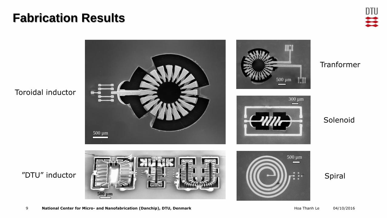
500 µm
500 µm
500 µm
300 µm
500 µm
Tranformer
Solenoid
Spiral
Toroidal inductor
”DTU” inductor
Fabrication Results

04/10/2016 Hoa Thanh Le 10 National Center for Micro- and Nanofabrication (Danchip), DTU, Denmark
1.5 mm 2 mm
4 mm
Fabrication Results

04/10/2016 Hoa Thanh Le 11 National Center for Micro- and Nanofabrication (Danchip), DTU, Denmark
Q-factor
L
Rac
Preliminary results
Toroidal inductor is wire-bonded on PCB test board (N=20, Ro=1 mm, Ri=0.5 mm)
Characterization

04/10/2016 Hoa Thanh Le 12 National Center for Micro- and Nanofabrication (Danchip), DTU, Denmark
Ifusing = 5.5A (RDC = 0.52 Ω)
IRMS = 2A
Au bond wires
Temperature Rise

04/10/2016 Hoa Thanh Le 13 National Center for Micro- and Nanofabrication (Danchip), DTU, Denmark
10
5
0
-5
-10
0.6
0.4
0.2
0
2
0
-2
30
20
10
0
6
4
2
0
80
60
40
0
20
VSW
VGS
VOUT
IL1 IL2
VCRES
0 0.5 1 1.5 2 2.5 3
Cycles
(b)
(a)
4.4 cm
4.8 cm
Inductor is wire-
bonded on PCB board
Gold bonding wire
(c)
Design of 100 MHz Class E Inverter

04/10/2016 Hoa Thanh Le 14 National Center for Micro- and Nanofabrication (Danchip), DTU, Denmark
Conclusion
Inductor Modeling
f-dependent Linternal, RAC
COMSOL
Design guideline
Customized Inductor
Number of turns
Inner & outer radius
Specs
Fabrication Process
CMOS-compatible
Cu-Si robust
2D & 3D air-core inductors
Through-Si Vias
Future Works
Test on SMPS
Packaging
Magnetics

04/10/2016 Hoa Thanh Le 15 National Center for Micro- and Nanofabrication (Danchip), DTU, Denmark
Acknowledgement
TinyPower Fund No. 67-2014-1