Embed Size (px)
Citation preview

DESIGN AND DEVELOPMENT OF GROOVE MICROMIXER FOR
LAMINAR BLOOD-REAGENT MIXING
SURAYA BINTI ABDUL RAHIM
A project report submitted in partial
fulfilment of the requirement for the award of the
Degree of Master of Electrical Electronic
Faculty of Electrical and Electronic Engineering
Universiti Tun Hussein Onn Malaysia
JULY 2013

iv
ABSTRACT
Mixing of two fluids is an essential process for most of microfluidic device
for Biomedical Micro-Electro-Mechanical System (Bio-MEMS) application. Mixing
also important in Lab-On-Chip (LOC) system because the chemical reaction carried
out in this system requires on-chip mixing. Mixing performance in this system relies
mainly on effective and rapid mixing of sample and reagent. Therefore, development
of groove micromixer for application of blood and reagent mixing carried out in this
project. In this study, two fluids involve in the mixing, which is the blood and
reagent (two type of reagent with lower and higher viscosity compared to blood).
Two pattern of the groove namely oblique groove and herringbone groove were
designed and simulated using CoventorWare2010 software at low Reynolds number.
The design of groove micromixer obtained by analyzing the geometries effect of
groove pattern on mixing performance of blood and reagent with the visualization of
simulation and evaluation of mixing performance for difference geometry parameter
of groove micromixer. In this study, it has been demonstrated that the Y-Shape mixer
with the groove structure located at the floor of the mixing channel increased the
mixing performance. Thus, the simulation result in this study shows that mixing
performance can be enhanced when depth and width of groove is 40% of the channel
width with the angle of an oblique groove is 45º. Whereas for the herringbone mixer,
enhancement of mixing performance occured when the depth and width of
herringbone groove is 25% of the channel width with the approximation of
asymmetric index is quarter of the width of mixing channel.

v
ABSTRAK
Pencampuran dua cecair adalah satu proses yang penting bagi kebanyakan
peranti bendalir mikro untuk aplikasi Bio-MEMS. Pencampuran juga penting dalam
sistem LOC kerana tindak balas kimia yang berlaku dalam sistem ini memerlukan
pencampuran pada komponen cip. Prestasi pencampuran dalam sistem ini bergantung
terutamanya pada keefektifan dan kecepatan pencampuran sampel dan reagen. Oleh
itu, reka bentuk alur pencampur mikro bagi aplikasi darah dan reagen telah
dijalankan dalam projek ini. Dalam kajian ini, dua cecair terlibat dalam proses
percampuran iaitu darah dan reagen (dua jenis kelikatan iaitu yang lebih rendah dan
lebih tinggi berbanding dengan darah). Dua corak alur iaitu serong dan alur tulang
hering telah direka dan disimulasi menggunakan perisian CoventorWare2010 pada
nombor Reynolds yang rendah. Reka bentuk alur pencampur dicipta dengan
menganalisis kesan geometri corak alur dan prestasi pencampuran darah dan reagen
dengan visualisasi simulasi dan penilaian prestasi pencampuran untuk geometri
parameter yang berbeza. Dalam kajian ini, simulasi pencampuran di antara darah dan
reagen telah berjaya menunjukkan bahawa bentuk Y pencampur dengan struktur alur
terletak di bahagian saluran pencampuran dapat meningkatkan prestasi pencampuran.
Oleh itu, hasil simulasi dalam kajian ini menunjukkan bahawa prestasi pencampuran
boleh dipertingkatkan apabila kedalaman dan lebar alur adalah 40% daripada lebar
saluran pencampur dengan sudut alur serong ialah 45 º. Manakala untuk pencampur
tulang hering, peningkatan prestasi pencampuran berlaku apabila kedalaman dan
lebar alur adalah 25% daripada lebar saluran pencampur dengan indeks simetri
adalah menghampiri suku daripada lebar saluran pencampuran.

vi
TABLE OF CONTENTS
CHAPTER CONTENTS PAGE
TITLE i
ACKNOWLEDGEMENT iii
ABSTRACT iv
TABLE OF CONTENTS vi
LIST OF FIGURE ix
LIST OF TABLE xii
LIST OF ABBREVIATION xiii
LIST OF SYMBOL xiv
LIST OF APPENDICES xv
CHAPTER I INTRODUCTION
1.1 Introduction 1
1.2 Background 1
1.2.1 Biomedical Micro-Electro-Mechanical
System (Bio-MEMS) 2
1.2.2 Overview on Microfluidic Device 3
1.2.3 Micro-Total Analysis Systems (µTAS)
and Lab-On-Chip (LOC) 4
1.3 Objective of Study 5
1.4 Problem Statement 6
1.5 Scope of Study 7

vii
1.6 Summary 7
CHAPTER II LITERATURE REVIEW
2.1 Introduction 8
2.2 Laminar Mixing for Blood and Reagent 8
2.2.1 Length Scale Object in Biology 9
2.2.2 Fluid Properties 10
2.2.3 Reynolds Number 12
2.2.4 Mass transport 14
2.2.5 Diffusion 15
2.3 Micromixer 16
2.4 Conclusion 23
CHAPTER III METHODOLOGY
3.1 Introduction 24
3.2 Methodology 25
3.2.1 Flow Chart 25
3.2.2 Geometric Parameter 29
3.3 The Y-Shape Micromixer 31
3.3.1 Difference of Width Mixing Channel 31
3.3.2 Length of Mixing Channel 32
3.4 The Y-Shape with Oblique Groove Mixer 32
3.4.1 Difference Aspect Ratio for Oblique Groove 33
3.4.2 Difference Depth for Oblique Groove 34
3.4.3 Difference Width for Oblique Groove 35
3.4.4 Difference of Angle for Oblique Groove 35
3.5 The Y-Shape with Herringbone Groove Mixer 37
3.5.1 Difference Width for Herringbone Groove 38

viii
3.5.2 Difference Asymmetry Index for
Herringbone Groove 39
3.6 Difference of Reagent Viscosity 40
3.7 Conclusion 42
CHAPTER IV RESULT AND DISCUSSION
4.1 Introduction 43
4.1.1 Evaluation Criterion of Mixing Performance 43
4.2 The Y-Shape Micromixer 45
4.2.1 Effect of Mixing Channel Width 45
4.2.2 Length of Mixing Channel 46
4.3 The Y-Shape Oblique Groove Mixer 49
4.3.1 Effect of Groove Aspect Ratio 49
4.3.2 Effect of Oblique Groove Depth 51
4.3.3 Effect of Oblique Groove Width 53
4.3.4 Effect of Oblique Groove Angle 54
4.4 Y-Shape Herringbone Groove Mixer 56
4.4.1 Effect of Herringbone Groove Depth 56
4.4.2 Effect of Asymmetry Index
of Herringbone Groove 57
4.5 Effect of Reagent Viscosity 59
4.6 Conclusion 62
CHAPTER V CONCLUSION AND RECOMMENDATION
5.1 Conclusion 63
5.2 Recommendation 64
REFERENCES 66
APPENDICES 71

ix
LIST OF FIGURE
FIGURE PAGE
2.1 A block model of solid material and a fluid contained
between two plates. 10
2.2 Pressure driven flow in a parallel plate channel. 13
2.3 The schematic diagram of oblique ridges mixer. 19
2.4 The schematic diagram for SHM. 20
2.5 The schematic diagram of connected groove mixer. 23
3.1 Flow chart for modelling and simulation of blood reagent
mixing. 26
3.2 Parameter geometry for (a) Y-Shape oblique groove
and (b) Y-Shape herringbone groove. 30
3.3 The 3D model of oblique groove for different aspect
ratio compare to channel height (a) aspect ratio is 0.125,
(b) aspect ratio is 0.25, (c) aspect ratio is 0.375, and
(d) aspect ratio is 0.5. 33
3.4 Parameter related to the geometry of the oblique groove
depth and width. 34
3.5 Schematic diagram of Y-Shape oblique groove with
different inlet angl, (a) θinlet = 26°, (b) θinlet = 45°,
and (c) θinlet = 56°. 36
3.6 Schematic diagram of Y-Shape oblique groove with
different groove angle, (a) θg = 26°, (b) θg= 45°,
and (c) θg = 56°. 36
3.7 The Y-Shape mixer with the herringbone groove,
(a) The 3D model of symmetry herringbone structure in
mixing channel, (b) 2D layout of symmetry index

x
of herringbone pattern. 38
3.8 The 2D layout for different asymmetry index of
herringbone structure, (a) 5μm distance at x-axis and
(b) 10μm distance at x-axis. 40
4.1 Cross section mixing visualization of Y-Shape micromixer
for blood and toluene. 44
4.2 Graph of standard deviation of viscosity distribution
for mixing of blood and toluene for Y-Shape micromixer
with different width of mixing channel. 46
4.3 Graph of standard deviation of viscosity distribution for
mixing of blood and toluene for Y-Shape micromixer
without groove and Y-Shape micromixer with groove. 47
4.4 Model contour for Y-Shape micromixer (a) without groove,
and (b) with groove. 48
4.5 Model contour and slice image for (a) 5μm groove width,
(b) 10μm groove width, (c) 15μm groove width, and
(d) 20μm groove width. 50
4.6 Graph of standard deviation of viscosity distribution
for mixing of blood and toluene for Y-Shape mixer
with different size of oblique groove. 51
4.7 Image cross section along x plane located at the bottom
and middle of groove structure for (a) 5μm groove depth,
(b) 10μm groove depth, and (c) 15μm groove depth. 52
4.8 Graph of standard deviation of viscosity distribution
for mixing of blood and toluene for Y-Shape oblique
groove with different depth of groove. 52
4.9 Image cross section along x plane located at the bottom
and middle of groove structure for (a) 10μm groove
width, (b) 15μm groove width, and (c) 20μm groove width. 53
4.10 Graph of standard deviation of viscosity distribution for
mixing of blood and toluene for Y-Shape oblique
groove mixer for different groove width. 54
4.11 Graph of standard deviation of viscosity distribution for
mixing of blood and toluene for oblique groove with 45º

xi
angle mixer with different groove angle. 55
4.12 Graph of standard deviation of viscosity distribution
for mixing of blood and toluene for Y-Shape oblique
groove mixer with different inlet angle. 56
4.13 Graph of standard deviation of viscosity distribution
for mixing of blood and toluene for Y-Shape herringbone
groove mixer with different depth. 57
4.14 Graph of standard deviation of viscosity distribution
for mixing of blood and toluene for Y-Shape herringbone
groove mixer for difference asymmetry index. 58
4.15 Graph of standard deviation of viscosity distribution for
laminar mixing of blood with low viscosity of
reagent (toluene). 60
4.16 Graph of standard deviation of viscosity distribution for
laminar mixing of blood with low viscosity of
reagent (benzyl). 60
4.17 The 3D translucency contour model for (a) Y-Shape without
groove mixer, (b) Y-Shape with oblique groove and
(c) Y-Shape with herringbone groove. 61

xii
LIST OF TABLE
TABLE PAGE
2.1 Length scale of typical objects in biology. 10
3.1 Geometries parameters for different width of mixing
channel. 32
3.2 Geometries parameters for micromixer without groove
and with groove. 32
3.3 Geometries parameter for different aspect ratio
of oblique groove. 33
3.4 Geometries parameter for the different depth of
oblique groove. 34
3.5 Specification dimension for various width of
oblique groove. 35
3.6 Geometries parameter for different oblique angle
when θ inlet1, 2 = 26º. 37
3.7 Geometries parameter for different oblique angle
when θ inlet1, 2 = 45º. 37
3.8 Geometries parameter for different oblique angle
when θ inlet1, 2 = 56º. 37
3.9 Geometries parameter for different depth of
herringbone groove. 38
3.10 Geometries parameter for different asymmetrical
index of herringbone groove. 39
3.11 The boundary condition of the blood and reagent. 41
3.12 Geometries parameter for three design of
Y-Shape micromixer. 42

xiii
LIST OF ABBREVIATION
Bio-MEMS - Biomedical Micro-Electro-Mechanical System
CFD - Computational Fluid Dynamics
FVM - Finite Volume Method
LOC - Lab-On-Chip
MEMS - Micro-Electro-Mechanical System
µTAS - Micro-Total Analysis Systems
SHM - Staggered Herringbone Mixer
SGM - Slanted Groove Mixer

xiv
LIST OF SYMBOL
- Cross sectional area
𝑦 - Hydraulic diameter
- Diffusion coefficient
- Depth of groove
- Depth of herringbone
- Height of channel
𝑡 - Height of inlet
- Length of channel
𝑡 - Length of inlet
- Dynamic viscosity
- Asymmetry index
𝑤 𝑡𝑡 - Wetted perimeter
- Density of fluids
- Volume flow rate
- Reynolds number
- Time
- Angle of oblique groove
- Angle of herringbone groove
𝑡 - Angle of inlet
- Velocity of fluids
- Kinematic viscosity
- Width of channel
- Width of groove
- Width of herringbone
𝑡 - Width of inlet
- Distance of particle

xv
LIST OF APPENDICES
APPENDIX PAGE
Paper submitted for review for 6th
Biomedical Engineering
International Conference (BMEiCON2013). 72

CHAPTER I
1 INTRODUCTION
1.1 Introduction
This chapter consists of two sections. The first section describes the
background of Biomedical Micro-Electro-Mechanical System (Bio-MEMS) field and
it contribution to biological application. Overview on microfluidic device and
development of Micro-Total-Analysis System (μTAS) and Lab-on-Chip (LOC)
device for Bio-MEMS application also given in this chapter. The second part of this
chapter provides an introduction of this project given by the objectives of this study
together with the scope and problem statement of this project.
1.2 Background
Bio-MEMS have emerged as a subset of Micro-Electro-Mechanical System
(MEMS) device for application in biomedical research and medical microdevices.
These systems encompass all interfaces of the life sciences and biomedical
disciplines with micro and nano scale systems. Bio-MEMS represent an exciting and
growing field with opportunities of improving the human condition and reducing the
cost of health care delivery.

2
1.2.1 Biomedical Micro-Electro-Mechanical System (Bio-MEMS)
Bio-MEMS can be defined as ‗‗a devices or systems constructed using
techniques inspired from micro or nano-scale fabrication, that are used for
processing, delivery, manipulation, analysis, or construction of biological and
chemical entities‘‘ (Bashir, 2004). Bio-MEMS device structure are typically
considered that having at least one feature‘s dimension in the submicron to micron
range from 100nm up to 200µm and other dimension of up to several milimeter
(Saliterman, 2005).
The integration of Bio-MEMS technology with microscale sensors, actuators,
microfluidics, micro-optics, and structural elements with computation,
communications, and controls for medicine application could contribute to the
improvement of human health (Polla, 2001). For example, microactuators are useful
in biomedical applications when biological objects or their environment needed to
controlled on the microscopic scale. Therefore, the ability to integrate many
microactuators in single chip makes it feasible to produce complex microsystem
capable of controlling many parameters (Judy, 2000).
Biological application is one of the most promising and challenging
application fields for MEMS and microsystem technology. The review of MEMS
technology in physiological aspect by Grayson, et al. (2004) emphasize that MEMS
have many characteristics that make it interesting for biological applications. For
example, the ability of MEMS device to control physical and chemical
characteristics for biological material on the micrometer and nanometer scale. They
also drawn attention to the fact that MEMS for biological applications is growing
rapidly with opportunity in certain areas such as biosensors, pacemakers,
immunoisolation capsules, and drug delivery. In addition, the significant of these
applications are due to the unique features of MEMS for it maximum impact
(Grayson et al., 2004).
The biological applications of MEMS and microfluidics are closely related
because the majority of devices for biological and medical analysis work with

3
samples in liquid form (Maluf, 2002). Moreover, microfluidic has emerged as a new
approach for improving performance and functionality of biochemistry and medical
analysis through miniaturization and integration system into single chip (Saliterman,
2005). The several advantage of miniaturized biochips are lower manufacturing
costs, reproducibility, small sample size and reagent used, improved signal-to-noise
ratio, improved response time, precise control of mixing, reacting and discarding of
waste products, in line embedded detection methods, and high throughput.
1.2.2 Overview on Microfluidic Device
Microfluidic is the outgrowth of fluidic and commonly related with the
technical field of working with fluids, mainly controlling their flows in a system of
channels. Microfluidics characterized by the small size of the channels and emerged
together with general area of MEMS, which become possible by applying the
microfabrication technique originally developed by microelectronic. Microfluidic
can be defined as a technology of handling small fluid flows in small device and
microfluidic device can be simply characterized by dominant (smallest) channel
width smaller than 1mm. Common present-day microfluidic device commonly use
channel widths in the region from 0.1 to 1mm (Tesar, 2007).
Microfluidic system consists of device usually connected by interconnection
channel and designed with objective to fulfil a particular task. The common passive
fluidic device consist of two terminal, passive flow through fluidic device with the
upstream input inlet and the output outlet terminal as a downstream exit (Tesar,
2007). For example, mixer used as separate device upstream from premixed-reaction
reactor and usually needed in microchemistry field. As well, many biological
processes such as antibody-antigen binding that required rapid and effective mixing.
Microfluidic device consist of channel and feature with precision
approximately 1µm that enable the manipulation of small volume of fluid. Such
controls bring several advantages. The advantage of small-scale device may be
different for particular application, but smaller device generally cheaper, need only

4
tiny amount of material. The several advantages of small scale device for
microchemistry application are better control of process due to high surface volume
ratio, less sample needed for analysis, more analysis simultaneously, portability,
safely handled of dangerous substance and approaching cellular size (Tesar, 2007).
1.2.3 Micro-Total Analysis Systems (µTAS) and Lab-On-Chip (LOC)
The development of the µTAS and LOC device actually from the application
of ―hard‖ and ―soft‖ fabrication technique for manufacturing the miniaturized
devices that will perform all or part of a biochemical analysis. The µTAS can be
describe as hybrid of multiple chips, integrated electronic, and external support
whereas LOC refer more specifically to a microfluidic chip or device that perform a
well-defined analytical task (Guber et al., 2004). The LOC device can be define as an
integrated and scale down laboratory function and processes to miniaturized single-
chip format task. The µTAS or LOC device is usually used to describe sensors and
devices with some level of integration of different functions and functionality
(Bhansali & Vaudev, 2012). These devices offer the several advantages such as
integrating sample handling, preparation, mixing, separation, lysing of cells, and
detection (Saliterman, 2005).
Microfluidics and sensing capabilities is a common feature that could make
LOC device closely related to Bio-MEMS and µTAS. Microfluidic device are the
primary component of most µTA and LOC device. Microfluidic can simply describe
as a study of transport in microchannel. Microfluidic device such as LOC device may
consist of channels, valves, mixers, pumps, filters, and heat exchanges. These
component can perform the operation such as metering, dilution, flow switching,
particle separation, mixing, pumping, incubation of reaction material and reagent,
sample dispensing or injection, and also may incorporate various detect schemes
(Saliterman, 2005).
The LOC device have been develop and used in wide range of biomedical
and other analytical application. This micro device can be categorized into two main

5
categories based on their final application which is hand-held LOC system and table-
top LOC system (Bhansali & Vaudev, 2012). The hand-held LOC system are
generally used to screen small sample for point-of-care testing while the table-top
LOC system are typically used to analysed many sample for high-throughput
application with interfaced with external detection system and pressure source.
Many area of biological interest desired microfabrication system for rapid, high
throughput and other requirement to achieve the specific goal. In most Bio-MEMs
field, it is commonly required to prepared, deliver, or manipulate microscopic
amount of bio-samples or reagent in microchannel. In µTAS and LOC device, the
manipulation of the fluid and it sample may be including biological material. The
primary of liquid transport in this microsystem may including whole blood, serum
(containing protein, and other chemistries), bacteria suspension, and various reagent
and buffer (Tian & Finehout, 2008).
Mixing is significant important in LOC system and bio-analysis system
because the reaction carried out on microscale required on-chip mixing of sample
and reagent. In this microsystem, fluid needed to be mixed with another fluid to
dilute a sample or to perform a controlled chemical reaction (W. Wang & Soper,
2007). Mixing in microfluidic system can be perform by incorporate a specific
mixing mechanism known as micromixer. Therefore, most of LOC device need to
include micromixer in the flow path.
1.3 Objective of Study
The objectives for this project are:
1. To design the groove micromixer for laminar blood-reagent mixing using
CoventorWare2010 software.
2. To observe the different geometry parameter of groove micromixer by
analyzing the geometric effect of groove pattern on mixing performance
for blood and reagent.
3. To evaluate the blood mixing performance with different viscosity of
reagent.

6
1.4 Problem Statement
Mixing in microfluidic device generally slow that make mixing in this
microchannel is difficult to achieve. In macroscale, mixing can be more effective
through turbulent transport, but in microscale, mixing driven by laminar flow. In the
laminar flow, the only mixing mechanism is diffusion, which is very slow due to low
Reynolds number. Since diffusion is relatively slow, specific mixing geometries are
required so that can shorten the diffusion length and decrease the mixing time.
Designing micromixer generally require fast mixing time, small device area, and
ability to integrate in a more complex system. Rapid mixing in micromixer achieved
by increasing the contact surface and decreasing the mixing path. All micromixers
are design to increase the interfacial area where the diffusion of two dissimilar fluids
can occur.
In the project, the design and development of groove micromixer are carried
out based on the concept chaotic advection through modification of microchannel
surface by groove pattern on microchannel floor where it can enhance laminar blood-
reagent mixing performance at low Reynolds number. The objective of this project is
to design and develop groove micromixer by observing the effect of geometric
parameter and analyzing the mixing performance of laminar blood and reagent
mixing. In this study, two fluids involve in the laminar mixing that the blood is the
centers point of fluid material and reagent fluid with lower and higher viscosity
compared to blood. The laminar mixing of the two fluids inside these micromixers
are simulated at Reynolds number less than 1. In this project, two design of groove
micromixer taken into consideration namely oblique groove mixer and herringbone
groove mixer. The design parameter of each groove mixer are developed based on
the evaluation of mixing performance in the numerical simulation result. Design and
development of groove micromixer for laminar blood-reagent mixing are carried out
by numerical simulation approach using CoventorWare2010 software.

7
1.5 Scope of Study
The scopes of this project are:
i. Design Y-Shape groove micromixer by using CoventorWare2010
software.
ii. Simulate mixer for laminar blood reagent mixing and observe the
geometries effect for the development of groove micromixer.
iii. Design and development of groove micromixer up to 500μm length.
1.6 Summary
Mixing of two fluids is an essential process for most of microfluidic device
such as Lab-On-Chip (LOC) device. Mixing performance in this microsystem relies
mainly on effective and rapid mixing of sample and reagent. Therefore, the objective
of this project is to design and develop groove micromixer for application of blood
and reagent mixing. In this study, numerical simulation of the fluid flow and mixing
are perform by using CoventorWare2010 software. The fundamental theory related to
laminar mixing and design concept of micromixer will be discus in the next chapter.

CHAPTER II
2 LITERATURE REVIEW
2.1 Introduction
This chapter overview the basic and fundamental theory involved in this
project. In this chapter, the fundamental theory related to laminar mixing for blood-
reagent and the design concept for micromixer in previous study are review. The first
section in this chapter discussed the properties of the fluid and characteristic of fluid
flow such as Reynolds number, mass transport and diffusion concept. The second
part of this chapter will discussed the basic concept design used for designing
micromixer and overview of previous study that focused on the concept design for
groove structure.
2.2 Laminar Mixing for Blood and Reagent
Fluid mechanics encompasses the study of all types of fluids under static,
kinematic and dynamic conditions. The study of properties of fluids is basic for the
understanding of flow or static condition of fluids. Generally, the manipulation of
microscopic amount of bio-samples or reagent occurs in microchannel. For that
reason, the overview of the fluid mechanics such as viscosity of fluid, principle of

9
fluid flow, and Reynolds number give the information of the fundamental related to
fluid and compartment of fluid flow in parallel microchannel. Fluid behaviour at the
microscale is often different from those at macroscale. Thus, the principle of mass
transport effect in microchannel mixing also be studied, which provide the
knowledge of molecular diffusion concept to enhanced the mixing performance in
micromixer design.
2.2.1 Length Scale Object in Biology
An integrated LOC device can incorporate many of the necessary
components and functionality of a typical room-sized laboratory into a small chip
that performs a specific biological or chemical analysis, including sample treatment,
transport, reaction, and detection (Saliterman, 2005). The fundamental properties of
fluid in micro or nano scale may differ significantly from those in larger devices.
Therefore, fluid and sample transport is a crucial issue in these LOC devices because
many biological and chemical processes and experiments take place in aqueous
environments (Hu & Li, 2007).
In order to design LOC device or microfluidic device for biological
application, length scales of the biological objects are necessary to considered.
According to Merriam Webster Dictionary, size can define as ‗physical magnitude,
extent, or bulk: relative or proportionate dimensions‘. The typical length scales or
size of some of the biological objects show in Table 2.1. From this table, it can be
seen that the diameter of the blood cell approximate 8µm, and the diameter for
average cell in human body around 10µm. Therefore, the minimum length scale for
designinig micromixer should not less than the diameter of an average cell in human
body.

10
Table 2.1: Length scale of typical objects in biology (Hu & Li, 2007).
Typical objects in biology Length scale
Diameter of glucose molecule 1 nm
Diameter of DNA helix 2nm
Diameter of insulin molecule 5nm
Thickness of cell wall (gram negative bacteria) 10nm
Size of typical virus 75nm
Diameter of the smallest bacterium 200nm
Diameter of red blood cell 8.4µm
Diameter of average cell in human body 10µm
Diameter of the largest bacterium 750µm
2.2.2 Fluid Properties
Fluid can be defined as a substances that deform continuously under the
application of shear (tangential) stress of any magnitude (Saliterman, 2005). Figure
2.1 illustrate a shear streass applied to the block of solid model and to the fluids film
contained between two plates. The right side model in this figure show the shearing
force applied to the solid object. The solid object was deforms but it will return to
original shape as long as the elastic limit is not exceeded. In contrast, a liquid or fluid
film in the left side model in this figure that located between two plate was deforms
after applying shearing force and stays deform after the shearing force is removed.
Figure 2.1: A block model of solid material and a fluid contained between two plates.
11
Fluid can be in form of gasses (i.e. air) or liquid (i.e. water). Liquid can be
characterized based on three important parameter which is it density, pressure and
viscosity. The density defined as the mass per unit volume. Pressure in the liquid
only depends on the depth that makes pressure increase when going from the surface
to the bottom and not affected by the shape of the vessel containing liquid.
Microchannel is not a closed system due to the inlet and outlet opening, the pressure
different induced externally at these opening is transmitted to the liquid and
consequently inducing the liquid flow (Ong, Zhang, Du, & Fu, 2008).
If the density of a fluid varies significantly due to moderate changes in
pressure or temperature, then the fluid is knows as compressible fluid. Generally,
gases and vapours under normal conditions classified as compressible fluids. In these
phases, the distance between atoms or molecules is large and cohesive forces are
small. Therefore, increase in pressure or temperature will change the density by a
significant value. If the change in density of a fluid is small due to changes in
temperature and or pressure, then the fluid is knows as incompressible fluid. All
liquids are classified under this category (Kothandaraman & Rudramoorthy, 2007).
The viscosity defined as an internal friction or resistance during setting fluid
into motion. The kinematic viscosities of fluid are another important parameter that
relates the dynamic viscosity to density that is defines as:
=𝜇
𝜌 (2.1)
Where is the kinematic viscosity, is the density or mass per unit volume
and is the dynamic viscosity.
Fluid classified as a Newtonian if the shear stress (shear force/area fluid
contact) is directly proportional to the rate of strain. Most of the gasses and fluid are
categorize in this category. However, if the fluid viscosity changes with the shear
stress, these fluids can be termed as Non-Newtonian fluid (i.e. blood). The use of
Non-Newtonian fluids as compared to Newtonian fluids is more promising for the
development of microfluidics devices. In non-Newtonian fluids, either the viscosity

12
grows (shear thickening) or decreases (shear thinning) with increasing shear rate.
There can be turbulent-like instabilities in flows of such fluids at low Reynolds
number. These "elastic turbulence" could be generated in microfluidic channels to act
as efficient mixers (Ong et al., 2008).
2.2.3 Reynolds Number
Fluid flow generally categorized into two flow regimes: laminar and
turbulent. Laminar flow characterized by smooth and constant fluid motion, whereas
turbulent flow characterized by vortices and flow fluctuations. Physically, the two
regimes differ in terms of the relative importance of viscous and inertial forces. The
flow of fluid can be considered as laminar, transition or turbulent is dependent on the
fluid density and viscosity, characteristic velocity, geometry of the channel and
whether the flow past an object.
The flow pattern typically classified based on the dimensionless number
know as Reynolds number. The flowing fluid maybe influenced by the properties of
fluid and flow which kinematic properties (velocity, viscosity, acceleration,
vorticity), transport properties (viscosity, thermal conductivity, diffusivity),
thermodynamic properties (pressure, thermal conductivity, density) and other
properties (surface tension, vapour pressure, surface accommodation coefficient)
(Nguyen & Wereley, 2002). Reynolds number can be describing as a ratio of
measurement between inertial force and viscous force in particular flow. This
dimensionless values can defines as:
=𝐼 𝑟𝑡 𝑎 𝑓𝑜𝑟𝑐
𝑉 𝑠𝑐𝑜𝑢𝑠 𝑓𝑜𝑟𝑐 =
𝜌𝑢𝐷ℎ𝑦𝑑
𝜇=
𝑢𝐷ℎ𝑦𝑑
𝑣 (2.2)
Where is the mean velocity of the fluid flow, 𝑦 is the hydraulic
diameter, is the kinematic viscosity, is the density or mass per unit volume and
is the dynamic viscosity. The different regime of behavior in Reynolds number can

13
be Re << 1 (viscous effect dominate inertial effect), Re ≈ 1 (viscous effect
comparable to inertial effects), and Re >> 1 (inertial effect dominate viscous effect).
Many microdevices have long straight passages with constant cross section as
illustrated in Figure 2.2. Flow through these channels is important flow phenomenon
at small length scales. The flows in this system are control by pressure gradient, the
pipe diameter or hydraulic mean diameter, the fluid properties like viscosity and
density and the pipe roughness. If the density of the flowing fluid is the same all over
the flow field at all times, then such flow called incompressible flow. Flow of liquids
considered as incompressible even if the density varies a little due to temperature
difference between locations.
Streamline defined as a trace of any point in a moving fluid. Usually, the
directions of streamline are parallel with the motion direction of the moving fluid.
Generally, a streamline can change its position and its shape in a steady state flow. A
stream tube made up by a bundle of streamline through all point of a closed curve.
Figure 2.2: Pressure driven flow in a parallel plate channel (Chakraborty, 2010).
In addition, many of these long straight passages have cross sectional
geometric that are different from circular pipe. The hydraulic diameter for different
shape of cross-sectional for parallel flow can be defines as:
𝑦 =4 𝑥 𝐶𝑟𝑜𝑠𝑠 𝑠 𝑐𝑡 𝑜 𝑎 𝑎𝑟 𝑎
𝑊 𝑡𝑡 𝑝 𝑟 𝑚 𝑡 𝑟=
4𝐴
𝑃𝑤𝑒𝑡𝑡 (2.3)
Where is the cross sectional area, and 𝑤 𝑡𝑡 is the wetted perimeter. The
concept of hydraulic diameter used to assess flows through both completely filled

14
channel as well as those only partially filled. The term ‗wetted perimeter‘ refers to
the perimeter of the channel that is in direct contact with the flow while the ‗area‘
refers to the area through which the flow is occurring. For the channel that are
completely filled, the wetted perimeter is simply the perimeter of the channel and the
area is the cross sectional area of the channel. The state parameter used to specify a
state at a location in a fluidic flow could be either volume or mass flow rate. The
volume flow rate of fluid flow defined as:
= (2.4)
Where is the volume flow rate, is the fluid velocity and is the cross
section area. The relationship between flow rate and velocity as a state parameter are
the main influence on the shape of the channel cross section.
2.2.4 Mass transport
Generally, in microfluidic systems the mass transport can be grouping into
two type of transport based on the nature of the driving agent behind the transport
which directed transport and statistical transport (Ong et al., 2008). Directed
transport controlled by exerting work on the fluid. These work results in a volume
flow of the fluid, where the flow usually be characterized by a direction and flow
profile. The work often generated mechanically by a pump or electrically by a
voltage. Flow that driven mechanically are knows as pressure-driven flow and flow
driven by a voltage called electro-osmotic flow. On the other hand, statistical
transport typically deals with concentration of the molecule. A typical situation of the
statistical transport is the transport of molecules from the side with high
concentration to the side with zero concentration (i.e. by the presence of a
concentration gradient).
Mass transport in microscale can also be categories based on transport effect
mechanism such as diffusive transport, advective transport, taylor-aris dispersion or
chaotic advection (Nguyen & Wereley, 2002). Diffusive transport are cause by the

15
random motion of molecule and knows as Brownian motion. The mixing rate in
these transports are determine by the flux of the diffusion. Moreover, the advection
transport can caused the mass transport due to a mass flux while the distributed
velocity profile across the microchannel due to a pressure-driven flow known as
taylor-aris dispersion. Convection transport at the fluid layer with different velocities
in the pressure-driven flow transportation mechanism causes as apparently higher
axial dispersion produced pure molecular diffusion.
Advection known as a transport of a substance within a moving fluid and
generally occur in the direction of the flow and it has no effect on the traversal
transport of the substance. Chaotic advection can be describe as a stirring flow occur
in other direction of advection whose generate the transverse component of the flow,
thus cause an exponential growth of the interfacial area and decrease in the striation
thickness can improve the mixing performance. The stirring flow can be generated
by the channel shape that stretch, fold, break and split the laminar flow over the
cross-section of the channel (Capretto, Cheng, Hill, & Zhang, 2011). These
transverse flows caused by either actively by external disturbance or passively by
spatially periodic structure. When the flow passes through each of the structure, also
called as the advection cycle, the cross sectional concentration distribution
transformed into the next distribution. Repeating these advection cycle stretches,
folds, and breaks up the fluids and leads to complete mixing (Nguyen & Wereley,
2002).
2.2.5 Diffusion
Diffusion is a statistical transport phenomenon. Diffusion occurs when there
is a concentration gradient of one kind of molecule within a fluid. In laminar flow,
two or more stream flowing in contact with each other only mixes by the diffusion.
This is not advantage when mixing is desirable; therefore, passive of active mixing
mechanisms is required. Particle movement by Brownian motion cause particle to
spread out over time to make the average concentration of particles throughout the

16
volume is constant. These concepts describe as the mean square displacement of a
particle from its origin is proportional to time:
2 = 2 (2.5)
Where is the distance a particle moves, is the amount of time, and is the
diffusion coefficient.
2.3 Micromixer
Generally, micromixer categorized as an active micromixer or passive
micromixer. Active micromixer use external energy for mixing process while passive
micromixer do not required external energy for mixing process but rely entirely on
diffusion or chaotic advection. The difference between these two types of
micromixer system is active mixing produces excellent mixing; however, the means
of achieving mixing could involve moving parts that are difficult to fabricate and
integrate into the microfluidic systems. On the other hand, passive mixing uses no
external energy input and depends mainly on the mechanism used to generate fluid
flow through the microchannel; therefore, only limited mixing can be achieved
(Bayraktar & Pidugu, 2006).
Active micromixer enhance the mixing performance by stirring or agitating
the fluid flow using some form of external energy supply. Active mixers typically
use acoustic/ultrasonic, electrophoretic, electrokinetic time-pulse, pressure
perturbation, electro-hydrodynamic, magnetic or thermal techniques to enhance the
mixing performance (Chia Yen Lee, 2011). In contrast, passive micromixer contain
no moving parts and require no energy input other than the pressure head used to
drive the fluid flows at a constant rate (Chia Yen Lee, 2011). In passive micromixer,
a fluid flow usually in laminar flow. Due to the inherently laminar characteristics of
micro-scaled flows, mixing in passive micromixer relies predominantly on chaotic
advection effects realized by manipulating the laminar flow within the microchannel

17
or by enhancing molecular diffusion by increasing the contact area and contact time
between the different mixing species (Capretto et al., 2011).
Rapid mixing in passive micromixer can be obtained by increasing the
contact surface between different fluid and decreasing the diffusion path between
them to improve molecular diffusion (Nguyen & Wereley, 2002). Many review on
mixing operation in micromixer done previously by Nguyen, et al. (2005), Hessel, et
al. (2005), Lee, C. Y. et al. (2011), and Capretto, et al. (2011) usually categorized
passive micromixer into several group based on mixed phase operation condition of
the mixer. Passive micromixer can be categorize into several group based on mixing
principle such as Y-Shape or T-Shape mixer (Hsieh, Lin, & Chen, 2013), (Ait
Mouheb, Malsch, Montillet, Solliec, & Henkel, 2012) parallel lamination (Wong,
Ward, & Wharton, 2004), injection (Miyake, Lammerink, Elwenspoek, & Fluitman,
1993), segmentation lamination (Sheu, Chen, & Chen, 2012), (Nimafar, Viktorov, &
Martinelli, 2012), sequential lamination (Yun & Yoon, 2004), focusing mixer
(Knight, Vishwanath, Brody, & Austin, 1998), chaotic advection (Stroock et al.,
2002), (Aubin, Fletcher, & Xuereb, 2005), (Yang, Huang, & Lin, 2005), (Yang,
Fang, & Tung, 2008), (Ansari & Kim, 2007), zig-zag mixer (Mengeaud, Josserand,
& Girault, 2002), obstacle mixer (C. K. Chung, Shihl, Chen, & Wang, 2008), (Y.-C.
Lin, Chung, & Wu, 2007), (Balbino, Azzoni, & de la Torre, 2013), split and
recombine mixer (Sudarsan & Ugaz, 2006), recirculation mixer (Y.-C. Chung, Hsu,
Jen, Lu, & Lin, 2004), (C. K. Chung, Shih, Tseng, Chen, & Wu, 2007), (Hamid,
Kamaruzzaman, & Jamil, 2011), (Alam & Kim, 2013), (Daghighi & Li, 2013),
groove or rib mixer (Yang et al., 2005), (D. Lin et al., 2013), (Kasiteropoulou,
Karakasidis, & Liakopoulos, 2013), and droplet mixer (Matsuyama, Mine, Kubo, &
Mae, 2011).
The final stage of all mixing concept in generally is molecular diffusion. The
mixing of micromixer based on molecular diffusion relies only on diffusive transport
and mixing only optimized by the geometrical design and different transport effect.
The rhombic mixer was reported by Hamid, et al. (2011) claims that fluid mixing of
the rhombic micromixer is closely related to the rhombic geometric and Reynolds
number. In this study, they also emphasize that the mixing is better if the reagent is

18
smaller in viscosity compared to blood based on the simulation result that show the
difficulty of mixing of blood with the high viscosity reagent.
The different geometry structure of micromixer based on several design
method could improve the mixing performance in microchannel. Mixing
performance in micromixer based molecular diffusion usually can be increase
through modification of geometry structure of mixer. Therefore, comparative
analysis method commonly used to evaluate the mixing performance with different
geometric shape micromixer. The comparative study reported by Hamid, et al.
(2011) claims that mixing performance for laminar blood-reagent fluid closely
related to the geometric of the micromixer and Reynolds number. Three type of
passive micromixer with different geometry channel which Y-Shape, Z-Shape and
Rhombic are use in this comparative analysis. Among three type of micromixer, Z-
Shape is superior compared to other two mixers due to larger recirculation of this
mixer that enhance mixing performance. They also draw intension to the fact that
viscosity of the fluid mixing effect the mixing process inside the mixing channel
(Hamid & Jamil, 2008), (Hamid et al., 2011). The numerical simulation result in this
work show that mixing performance is better if the reagent viscosity is smaller
compared to the blood.
Micromixer based on chaotic advection method can enhance mixing in
microchannel by introduces secondary flow in mixing channel known as chaotic
advection. These methods used either in a continuous flow or in multiphase flow.
According to Nguyen, et al. (2005), chaotic process used as a basic design concept in
generation of advection transportation by the modification of the channel shape for
stretching, folding, and breaking of the laminar flow. In chaos condition, the
necessary conditions are need such as the streamline should cross each other at
different times. These effects were occurring in a time-periodic flow or spatially
periodic flow. Chaotic advection can be generated by stirring the flow which is very
effective for small Reynolds number due to the concepts of splitting, stretching,
folding, and breaking up in the laminar flow (Nguyen & Wu, 2005). Rips or grooves
on the channel wall can produced chaotic advection. In one of the earlier works,
Stroock et al. (2002) proposed chaotic mixer based on bas-relief structure design on
the floor of the channel to generate transverse flow in microchannel by using steady
19
axial pressure gradient. Two design of bas-relief method reported which is the
oblique ridges mixer by placing ridges on the floor of the channel at an oblique
angle, and patterns of grooves on the floor of the channel known as Staggered
Herringbone Mixer (SHM).
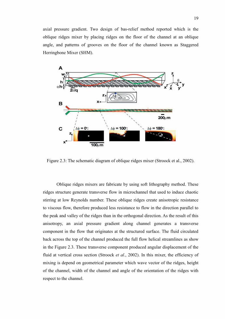
Figure 2.3: The schematic diagram of oblique ridges mixer (Stroock et al., 2002).
Oblique ridges mixers are fabricate by using soft lithography method. These
ridges structure generate transverse flow in microchannel that used to induce chaotic
stirring at low Reynolds number. These oblique ridges create anisotropic resistance
to viscous flow, therefore produced less resistance to flow in the direction parallel to
the peak and valley of the ridges than in the orthogonal direction. As the result of this
anisotropy, an axial pressure gradient along channel generates a transverse
component in the flow that originates at the structured surface. The fluid circulated
back across the top of the channel produced the full flow helical streamlines as show
in the Figure 2.3. These transverse component produced angular displacement of the
fluid at vertical cross section (Stroock et al., 2002). In this mixer, the efficiency of
mixing is depend on geometrical parameter which wave vector of the ridges, height
of the channel, width of the channel and angle of the orientation of the ridges with
respect to the channel.

20
Improved mixing has also been realized through the used of groove channel
as generator of secondary flow. Staggered Herringbone Mixer (SHM) design based
on subjected the fluid to a repeated sequence of rotational and extensional local flow
that as result produces a chaotic flow. These sequences of local flows are achieved
in the SHM by varying the shape of the grooves as a function of axial position in the
channel. In the SHM, the efficiency of mixing is controlled by two parameters which
asymmetry of the herringbones and the amplitude of the rotation of the fluid in each
half cycle. The angular displacement in this design controlled by the geometry of the
ridges and the number of herringbones per half cycle as illustrated in the Figure 2.4.
In this design, they also claim that symmetric herringbones structure do not induced
transverse flow, thus flow becomes non chaotic. Therefore, the change of
asymmetrical index can induced chaotic flow and contributes in the controlling of
the cross-sectional area will involved in the chaotic flow.
Figure 2.4: The schematic diagram for SHM (Stroock et al., 2002).
The effective designs of groove on wall attract many researchers to
investigate the effect of geometric parameter of groove structure on the mixing
performance in microchannel. The most common geometries of grooved micromixer
are Slanted Groove Mixer (SGM) and SHM, both embedded on the floor of the
microchannel. The SGM mixer designed with the angle respect to axial direction,
whereas SHM groove have the shape of herringbone pattern. The advection of the

21
fluid is enhance through the fluid transported along the oblique grooves to the
downstream edges of the microchannel (outlet) while the herringbone pattern of the
SHM generate two counter rotating helical flow with the asymmetry of the SHM
groove generate the chaotic flow profile.
Two-step of design protocol suggested and discussed by Sabotin, et al. (2012)
for designing groove pattern micromixer. The first step is by fixing the channel
aspect ratio until the suitable groove depth achieved. Then the suitable groove depth
stayed constant until other favourable geometry of the groove are obtain. The second
step is the suitable groove geometry was further examined in various six-groove
configurations. They also conclude that every groove in the groove design have its
own mixing potential for enhance the mixing process in microchannel. They also
show that rounding of inner groove‘s corner can improve mixing efficiency (Sabotin,
Tristo, Junkar, & Valentinčič, 2013).
Numerical investigation carry out by Yang, J.-T., et al. (2005) to study the
effect of geometric parameter of SHM with pattern groove by using the Taguchi
method to observed the influence of geometric parameter on SHM performance.
Numerical simulation result reveal that depth ratio and asymmetry index of the
groove are the most geometric parameter that effect the mixing performance of a
SHM follow by groove intersection angle and upstream to downstream channel
width ratio. In this study, they also draw intention to the effect of flow rate inside the
mixing channel that play one of the most significant roles in the mixing performance
of the SHM design (Yang et al., 2005).
The effect of various geometrical parameter of a SHM on the mixing
performance also performed by Aubin, J. et al. (2005) by using particle tracking
method. In this study, the plotting of particles located at different axial position along
channel mixer showing the distribution of the striation thickness corresponding to
particle trace pattern due to mixing behavior. The results proved that the number of
grooves per mixing cycle does not affect the mixing quality. On the other hand, a
larger groove depth and width allow the maximum striation thickness to be rapidly
reduced, without increasing the pressure drop across the mixer. They also highlighted

22
that the wide grooves can create significant dead zones in the microchannel, whereas
deep grooves improve the spatial mixing quality (Aubin et al., 2005).
Shape optimization of a SHM was also carry out by using numerical
optimization technique by Ansari, M. A. et al (2007) to optimize the shape of the
grooves on a single wall of the channel. Two design variables which is the ratio of
the groove depth to channel height ratio and the angle of the groove are selected for
optimization. In this study, the simulation performed with the mixing index is used as
the objective function. The simulation results obtain by using the shape optimization
technique show that the mixing is very sensitive to the shape of the groove which can
be used in controlling the mixing in microdevices. Moreover, they also claim that the
shape optimization of a SHM could increases the mixing near the inlet of the mixer.
In this work, they conclude that the mixing is affected by the depth of the groove
much more than the angle of the groove. In addition, pressure drop characteristic are
also increases with an increasing in the angle of the groove, and also with a
decreasing in the ratio of groove depth to channel height (Ansari & Kim, 2007).
In general, the patterned-groove micromixer mainly designs with the groove
on a single side of a channel to generate transverse components and therefore enlarge
the fluidic interface to enhance mixing. Through this design, the fluid is guide to
transfer onto the bottom of the main channel only by anisotropy surface structure on
the floor of the mixing channel. Therefore, the connected grooves channel introduced
by Yang, et al. (2008) give a new concept of groove structure by employed groove on
the bottom and side of the microchannel to promote the mixing. This mixer design
composes of bottom groove along the sidewall groove to the top of the mail channel.
This structure can cause the helical flow with a short pitch and generate the intense
transverse field. The geometrical schematic of connected groove mixer illustrated in
Figure 2.5.
The chaotic mixer reported by Stroock, et al. (2002) open the new way to
develop the micromixer with 3D effect without going through the 3D complexities
by embedding herringbone structure on the floor of the channel. This idea was extend
by Wang, et al. (2012) by fabrication of cylindrical grooves design. In this work,
three mixers are fabricate by embedding cylindrical grooves in to the main channel.

23
Their simulated and experimental results confirmed that the mixing enhancement
occur in this mixer. They conclude that the effect of cylindrical grooves is more
obvious at greater flow rates and this design are easily incorporated into a total
microfluidic system (L. Wang, Liu, Wang, & Han, 2012).
Figure 2.5: The schematic diagram of connected groove mixer (Yang et al., 2008).
2.4 Conclusion
As a conclusion, there are several method used to design the micromixer for
laminar flow. Many groove structure previously reported by fabricate the groove
structure inside the mixing channel. These structures are suitable method to enhance
the mixing performance for laminar mixing especially at low Reynolds number.
Groove pattern on the mixing channel floor are the basic design can be implement to
enhance the laminar mixing for blood and reagent. Moreover, these designs are
simple and easily fabricate inside the microchannel by using soft lithography
method.

CHAPTER III
3 METHODOLOGY
3.1 Introduction
This chapter consists of two main sections that discuss the methodology used
to conduct this project. In this chapter, the first section describes the process flow for
modelling and simulation of laminar blood and reagent mixing. In this section, the
design process of groove micromixer explained in detail to describe the process flow
used in this study in order to design and develop the groove micromixer. Second
section discussed the the geometries specification of each parameter design for Y-
Shape micromixer model. In this section, the Y-Shape micromixer design are divided
into three stage, the first stage is design the Y-Shape of micromixer without groove
structure, and then the Y-Shape mixer with the oblique groove and lastly the Y-
Shape mixer with herringbone groove structure. At the end of this chapter, all the
model design structure are simulated with two different viscosity of reagent. The
properties of two reagents with their boundary condition are given this chapter. All
the modelling and simulation of the groove micromixer design are performed using
CoventorWare2010 software.

66
REFERENCES
Ait Mouheb, N., Malsch, D., Montillet, A., Solliec, C., & Henkel, T. (2012).
Numerical and Experimental Investigations of Mixing in T-shaped and Cross-
Shaped Micromixers. Chemical Engineering Science, 68(1), 278-289. doi:
http://dx.doi.org/10.1016/j.ces.2011.09.036
Alam, A., & Kim, K.-Y. (2013). Mixing Performance of a Planar Micromixer with
Circular Chambers and Crossing Constriction Channels. Sensors and
Actuators B: Chemical, 176(0), 639-652. doi: 10.1016/j.snb.2012.09.047
Ansari, M. A., & Kim, K.-Y. (2007). Shape Optimization of a Micromixer with
Staggered Herringbone Groove. Chemical Engineering Science, 62(23),
6687-6695. doi: 10.1016/j.ces.2007.07.059
Aubin, J., Fletcher, D. F., & Xuereb, C. (2005). Design of Micromixers using CFD
Modelling. Chemical Engineering Science, 60(8–9), 2503-2516. doi:
10.1016/j.ces.2004.11.043
Balbino, T. A., Azzoni, A. R., & de la Torre, L. G. (2013). Microfluidic Devices for
Continuous Production of pDNA/Cationic Liposome Complexes for Gene
Delivery and Vaccine Therapy. Colloids and Surfaces B: Biointerfaces,
111(0), 203-210. doi: http://dx.doi.org/10.1016/j.colsurfb.2013.04.003
Bashir, R. (2004). BioMEMS: State-of-the-Art in Detection, Opportunities and
Prospects. Advanced drug delivery reviews, 56(11), 1565-1586.
Bayraktar, T., & Pidugu, S. B. (2006). Characterization of Liquid Flows in
Microfluidic Systems. International Journal of Heat and Mass Transfer,
49(5–6), 815-824. doi: 10.1016/j.ijheatmasstransfer.2005.11.007
Bhansali, S., & Vaudev, A. (2012). MEMS for Biomedical Applications: Woodhead
Publishing.

67
Capretto, L., Cheng, W., Hill, M., & Zhang, X. (2011). Micromixing Within
Microfluidic Devices. In B. Lin (Ed.), Microfluidics (Vol. 304, pp. 27-68):
Springer Berlin Heidelberg.
Chakraborty, S. (Ed.). (2010). Microfluidics and Microfabrication: Springer.
Chia Yen Lee, C. L. C., Yao Nan Wang, Lung Ming Fu. (2011). Microfluidic Mixing:
A Review. [Journal]. International Journal of Molecular Science, 12, 3263-
3287. doi: doi:10.3390
Chung, C. K., Shih, T. R., Tseng, T. C., Chen, T. C., & Wu, B. H. (2007). Design and
Simulation of a Rhombic Micromixer for Rapid Mixing. Paper presented at
the Nano/Micro Engineered and Molecular Systems, 2007. NEMS '07. 2nd
IEEE International Conference on.
Chung, C. K., Shihl, T. R., Chen, Y. S., & Wang, C. H. (2008). Mixing Process of an
Obstacles Micromixer with Low Pressure Drop. Paper presented at the
Nano/Micro Engineered and Molecular Systems, 2008. NEMS 2008. 3rd
IEEE International Conference on.
Chung, Y.-C., Hsu, Y.-L., Jen, C.-P., Lu, M.-C., & Lin, Y.-C. (2004). Design of
Passive Mixers Utilizing Microfluidic Self-Circulation in the Mixing
Chamber. Lab on a Chip, 4(1), 70-77.
Daghighi, Y., & Li, D. (2013). Numerical Study of a Novel Induced-Charge
Electrokinetic Micro-mixer. Analytica Chimica Acta, 763(0), 28-37. doi:
http://dx.doi.org/10.1016/j.aca.2012.12.010
Grayson, A. C. R., Shawgo, R. S., Johnson, A. M., Flynn, N. T., Yawen, L. I., Cima,
M. J., & Langer, R. (2004). A BioMEMS Review: MEMS Technology for
Physiologically Integrated Devices. Proceedings of the IEEE, 92(1), 6-21.
doi: 10.1109/jproc.2003.820534
Guber, A. E., Heckele, M., Herrmann, D., Muslija, A., Saile, V., Eichhorn, L., . . .
Knebel, G. (2004). Microfluidic Lab-On-a-Chip Systems Based on
Polymers—Fabrication and Application. Chemical Engineering Journal,
101(1–3), 447-453. doi: doi.org/10.1016/j.cej.2004.01.016
Hamid, I. S. L. A., & Jamil, M. M. A. (2008). Reynolds Number Effect in Designing
a Micromixer for Biomems Application. Universiti Tun Hussein Onn
Malaysia.

68
Hamid, I. S. L. A., Kamaruzzaman, S. W., & Jamil, M. M. A. (2011). Modeling and
Simulation of Rhombic Micromixer for Laminar Blood Mixing. Journal of
Engineering Technology, 1, 14-18.
Hsieh, S.-S., Lin, J.-W., & Chen, J.-H. (2013). Mixing Efficiency of Y-Type
Micromixers with Different Angles. International Journal of Heat and Fluid
Flow(0). doi: http://dx.doi.org/10.1016/j.ijheatfluidflow.2013.05.011
Hu, G., & Li, D. (2007). Multiscale Phenomena in Microfluidics and Nanofluidics.
Chemical Engineering Science, 62(13), 3443-3454. doi:
10.1016/j.ces.2006.11.058
Jian Chen, J., Ren Lai, Y., Tang Tsai, R., Der Lin, J., & Yang Wu, C. (2011).
Crosswise ridge micromixers with split and recombination helical flows.
Chemical Engineering Science, 66(10), 2164-2176. doi:
10.1016/j.ces.2011.02.022
Judy, J. W. (2000). Biomedical Applications of MEMS. Paper presented at the
Measurement Science and Technology Conference: Anaheim, CA.
Kasiteropoulou, D., Karakasidis, T. E., & Liakopoulos, A. (2013). Mesoscopic
Simulation of Fluid flow in Periodically Grooved Microchannels. Computers
& Fluids, 74(0), 91-101. doi:
http://dx.doi.org/10.1016/j.compfluid.2013.01.010
Knight, J. B., Vishwanath, A., Brody, J. P., & Austin, R. H. (1998). Hydrodynamic
Focusing on a Silicon Chip: Mixing Nanoliters in Microseconds. Physical
Review Letters, 80(17), 3863-3866.
Kothandaraman, C. P., & Rudramoorthy, R. (2007). Fluid Mechanics and Machinery:
NEW AGE INTERNATIONAL (P) LIMITED, PUBLISHERS.
Lin, D., He, F., Liao, Y., Lin, J., Liu, C., Song, J., & Cheng, Y. (2013). Three-
Dimensional Staggered Herringbone Mixer Fabricated by Femtosecond Laser
Direct Writing. Journal of Optics, 15(2), 025601.
Lin, Y.-C., Chung, Y.-C., & Wu, C.-Y. (2007). Mixing Enhancement of the Passive
Microfluidic Mixer with J-shaped Baffles in the Tee Channel. Biomedical
Microdevices, 9(2), 215-221. doi: 10.1007/s10544-006-9023-5
Maluf, N. (2002). An Introduction to Microelectromechanical Systems Engineering.
Measurement Science and Technology, 13(2), 229.
Matsuyama, K., Mine, K., Kubo, H., & Mae, K. (2011). Design of Micromixer for
Emulsification and Application to Conventional Commercial Plant for

69
Cosmetic. Chemical Engineering Journal, 167(2–3), 727-733. doi:
http://dx.doi.org/10.1016/j.cej.2010.09.085
Mengeaud, V., Josserand, J., & Girault, H. H. (2002). Mixing Processes in a Zigzag
Microchannel: Finite Element Simulations and Optical Study. Analytical
Chemistry, 74(16), 4279-4286. doi: 10.1021/ac025642e
Miyake, R., Lammerink, T. S., Elwenspoek, M., & Fluitman, J. H. (1993). Micro
Mixer with Fast Diffusion. Paper presented at the Micro Electro Mechanical
Systems, 1993, MEMS'93, Proceedings An Investigation of Micro Structures,
Sensors, Actuators, Machines and Systems. IEEE.
Nguyen, N.-T., & Wereley, S. T. (2002). Fundamental and Application of
Microfluidics: Artech Houe.
Nguyen, N.-T., & Wu, Z. (2005). Micromixers—a Review. [Journal]. Journal of
Micromechanics and Microengineering, 15(2), R1. doi: 10.1088
Nimafar, M., Viktorov, V., & Martinelli, M. (2012). Experimental comparative
mixing performance of passive micromixers with H-shaped sub-channels.
Chemical Engineering Science, 76(0), 37-44. doi: 10.1016/j.ces.2012.03.036
Ong, S.-E., Zhang, S., Du, H., & Fu, Y. (2008). Fundamental Principles and
Applications of Microfluidic Systems Frontiers in Bioscience 13. doi:
http://dx.doi.org/10.2741/2883
Polla, D. L. (2001). MEMS Technology for Biomedical Applications. Paper presented
at the Solid-State and Integrated-Circuit Technology, 2001. Proceedings. 6th
International Conference on.
Sabotin, I., Tristo, G., Junkar, M., & Valentinčič, J. (2013). Two-Step Design
Protocol for Patterned Groove Micromixers. Chemical Engineering Research
and Design(0). doi: 10.1016/j.cherd.2012.09.013
Saliterman, S. S. (2005). Fundamental of BioMEMS and Medical Microdevices:
SPIE.
Sheu, T. S., Chen, S. J., & Chen, J. J. (2012). Mixing of a Split and Recombine
Micromixer with Tapered Curved Microchannels. Chemical Engineering
Science, 71(0), 321-332. doi: 10.1016/j.ces.2011.12.042
Stroock, A. D., Derringer, S. K. W., Ajdari, A., Mezić, I., Stone, H. A., & Whitesides,
G. M. (2002). Chaotic Mixer for Microchannels. [Article]. Science,
295(5555), 647.

70
Sudarsan, A. P., & Ugaz, V. M. (2006). Multivortex micromixing. Proceedings of the
National Academy of Sciences, 103(19), 7228-7233. doi:
10.1073/pnas.0507976103
Tesar, V. (2007). Pressure-Driven Microfluidic: Artech House.
Tian, W.-C., & Finehout, E. (2008). Microfluidiics for Biological Applications:
Springer.
Wang, L., Liu, D., Wang, X., & Han, X. (2012). Mixing Enhancement of Novel
Passive Microfluidic Mixers with Cylindrical Grooves. Chemical
Engineering Science, 81(0), 157-163. doi: 10.1016/j.ces.2012.07.004
Wang, W., & Soper, S. A. (2007). Bio-MEMS Technologies and Application: CRC
Press.
Wong, S. H., Ward, M. C. L., & Wharton, C. W. (2004). Micro T-mixer as a rapid
mixing micromixer. Sensors and Actuators B: Chemical, 100(3), 359-379.
doi: 10.1016/j.snb.2004.02.008
Yang, J.-T., Fang, W.-F., & Tung, K.-Y. (2008). Fluids Mixing in Devices with
Connected-Groove Channels. Chemical Engineering Science, 63(7), 1871-
1881. doi: 10.1016/j.ces.2007.12.027
Yang, J.-T., Huang, K.-J., & Lin, Y.-C. (2005). Geometric Effects on Fluid Mixing in
Passive Grooved Micromixers. Lab on a Chip, 5(10), 1140-1147.
Yun, K.-S., & Yoon, E. (2004). Microfluidic Components and Bio-reactors for
Miniaturized Bio-chip Applications. Biotechnology and Bioprocess
Engineering, 9(2), 86-92. doi: 10.1007/bf02932989