Embed Size (px)
Citation preview

DESIGN AND DEVELOPMENT OF A MILK MINI - PASTEURISER
Christopher James Early
A pro;"act. report submitted to the Faculty of Engineering, University of the Witwatersrand, Johannesburg, in partial fulfilment of the requirements for the degree of Master of Science in Engineering.
Johannesburg, 1989

DECLARATION
I declare that this, project report is own,unaided work. It is being submitted for the Degree of Master of Science in Engineering in the University of the Witswatersrand, Johannesburg. It has not been submitted before for any degree or examination in any other University.

ABSTRACT
This Project Report identifies, in the Dairy Industry, a market . need which can be satisfied by the development of an annular laminar flow convection assisted milk pasteuriser.
It is shown, through experimental work on a full sized model, that the original design concepts envisaged were unsound, but that a revised design could prove to be commercially viable.
Mathematical relationships are derived relating to the specific flow and heat exchange conditions. Comparison of these results with existing publications enhances the findings of some other workers, while casting doubt on the validity of certain accepted material.
In keeping with modern farming trends, the report examines the feasibility of PC usage in this application and offers it as an alternative to a proprietary control system.

ACKNOWLEDGEMENTS
The assistance of Mr D Cipolat for his contribution as Internal Supervisor at the University of the Witwatersrand; and of Mr C M Glynn, Managing Director of AVAC (Pty) Ltd, in the manufacture of the project model, is gratefully acknowledged.

CONTENTS
DECLARATION iiABSTRACT H iACRNUWr.EDGKMBNTS i vCONTENTS VLIST OF FIGURES viiiLIST OF TABLES ■ ixLIST OF SYMBOLS xi
CHAPTER 1 INTRODUCTION 1
1.1 Purpose of Study 11.2 Problem Definition 11.3 Structure of Report 4
CHAPTER 2 LITERATURE SURVEY 8
2.1 General 82.2 Ilent Transfer 92.3 Fluid Flow 172.4 Mi Ik Pasteurisation 182.5 Pasteurisation Plant 252.6 Market Assessment 27
CHAPTER 3 THEORETICAL REQUIREMENTS 32
3.1 Conceptual Design

CHAPTER 4 MODEL DESIGN
GeneralModel ConstructionLimitations
CHAPTER 5 TEST OF MODEL
General5.2 Test Method
ProcedureObservations <:n Test ResultsDetermination of Flow ConditionDerivation of Decay TimeDerivation of LMTD FactorComparison with Alternative CorrelationsRegenerative 1Seat ExchangerSummary and Conclusions
CHAPTER 6 PROTOTYPE DESIGN
General
End PlatesHolding Tube
Diversion ValvesAssemblyPasteuriser Control System

CHAPTER 7 SUMMARY OF CONCLUSIONS 64
7.1 General 047.2 Validity 647.3 Existing Data 047.4 Experimental Data 857.5 Stagnation 857.6 Heat Transfer 657.7 Controls 057.8 Practical Application 867.9 Commercial Application 867.10 Summary B6
APPENDIX A Initial Calculations 08
APPENDIX B Test Results 90
APPENDIX c Consolidated Test Results 109
APPENDIX D Determination of Flow Condition 126
APPENDIX E Derivation of Decay Time 126
APPENDIX tf Derivation of LMTD 131
APPENDIX G Determination of Dimensionless Groups 132
APPENDIX H Control System Data 134
APPENDIX I Patent Registration 14l>
REFERENCES 142
vii

LIST OF FIGURES
Figure Page
1.1 Conceptual Design of Milk Pasteuriser 2
3.1 Anticipated Flow, Regenerative Exchanger 343.2 Regenerator: Anticipated Temperature
Gradient 36
4.1 Section and Elevation of Model 404.2 Location and Numbers of Therrometers 40
5.1 Test Rig with Convection Assisted Flow 465.2 Flow Patterns 52
6.1 General Arrangement of Pasteuriser 73
Cl Corrected Mean Temperatures T^sts 7,6 & 9 121C2 Corrected Mean Temperatures '’’eats 15,16,17 122C3 Horizontal Temperature Gradients 123C4 Diagonal Temperature Gradients 124C5 Vertical Temperature Gradients 125
HI General Arrangement of Control System 136H2 Primary Control Requirements 137H3 Temperature Control Cycle Logic 130f'4 Time Control Cycle Logic 139

LIST OP TADfjKS
Table Page
Bl Annular Thickness 90B2 Themoneter Corrections 91
Cl Sequence of Panels PilledBottom Flow Connection - No HeatTop Flow Connection - No Heat 109
C2 Sequence of. Panels FilledConvection AssistedConvection Opposed 110
C3 Sequence of Panels ClearedBottom Flow Connection - No HeatTop Flow Connection - No Heat 111
C4 Sequence of Panels ClearedConvection AssistedConvection Opposed 1
C5 Time Taken for Filling from Zero BaseBottom Flow Connection - No HeatTop Flow Connection - No Heat 113
C6 Time Taken for Filling from Zero BaseConvection AssistedConvection Opposed
Top Flow Connection - No Heat

Time Taken to Clear from Zero Basi Convection Assisted Convection opposed
Time Taken to Corrupt per Panel Convection Assisted Convection Opposed
Tinm Taken to Corrupt per Pane I Bottom Flow Connection - No Heat Top Plow Connection - No Heat
Time Taken to clear per Panel Convection Assisted Convection Opposed
Time Taken to Clear per Panel Bottom Flow Connection - No Heat Top Flow Connection - No Heat
Draft Control Software
a&xio

T.IST nr SYMBOLS
Quantity Symbol
Heat TransJiev Flux QOverall Heat Transfer Co-efficient u
Temperature TReyno Iris No ReGvashoC No GrPrandtl No PtPeclet No PeNusselt No NuSurface Neat Transfer Co-efficient hResistivity ' RDiameter DThermal Conductivity kLength 1Width wMass mVelocity vDensity fDynamic Viscosity TSpecific Heat cpMass Velocity GCo-efficient of Thermal Expansion Cubic f$Pressure P
Equivalent Diameter D„Equivalent Diameter - Stephan HEDH<a> dhEquivalent Diameter - Martinelli HEDH'3 ’ dEquivalent Diameter - Pohlhauaen HEDH‘31 SInsUlf Di/inin I r-i- rl.Outside Diameter d«,Dimensionless Factors fl,F,C,o,f
3?"

CHAPTER 1
INTRODUCTION
1.1 Purpose of Study
The purpose of this report was to validate theconceptual design oi' the pasteuriser, as shown in' Figure J.J.
1.2 Problem Definition
Discussions with small scale milk producers over a three year period indicated a need in the market for a packaged milk pasteurising plant capable of rrecessing 50 to 200 litres of milk per hour to acceptable standards of hygiene.
Conventional commercial milk pasteurisers areavailable in capacities from 250 1/h upwards,however, this equipment is ex import and thus prohibitively expensive.
The smallest locally assembled unit is 750 1/h. Aunit of 450 1/h had been previously assembledlocally but production of this unit was discontinued due to technical problems associated with holding times as defined in section 1.2.1 following.
Conventional small pasteurisers are scaled downversions of large industrial plants, and most operate with either steam or hot water heated plate heat exchangers, using an element of regeneration.

Temperature
1
<U
A Figure 1.1 Conceptual Design of Milk Pasteuriser
ii- 25x

The <’oaV. of Uhc control and recording system,roqui i ,'<.1 umli'f I lu* Milk Ily-ti.'iwH11 * , ilor-H mil decrease with a reduction in unit capacity, and thus becomes a disproportionately high percentage of the unit coat.
It was propoeeu that this cost could be RUbstnnl.in !1y vf»duc<»d by thf* une of a compuV.er, in that, with suitable software, the cont ol andrecording functions could be undertaken by a PC already in use by a farmer for either accounting, feed control or other purposes.
The following criteria limited the design, in that practical considerations must take precedence over design efficiency.
1.2.1 Legislation
The unit must pasteurise to meet the requirements of t-hr Rlflndavd Milk fiy T,nwR<i' , f»xt.raohn of whichare as? follows: -
"The pasteurisation of milk shall be performed by heating every particle of milk to, and holding it at, a temperature of at least 72'C for at least 15 HPoondR, the said process being hereinafterreferred to as 'the high-temperature short-timemethod'. (HTST)
Apparatus used for pasteurising milk shall be so designed and operated and shall be provided withcontrols adequate so as to ensure that every particle of the milk is subject to the prescribed range of temperature for the prescribed period.
The rf’noj'd required t-o bn kept in terms of

Rub-spction (5) and all Lemperatufe charts shall be completed at the end of each day, shall be accurate anii rwmf>)ete and ahai t at all times for a period o£ not less than six months be kept available for inspection by the medical officer of health”.
1.2.2 Hygiene
The unit must be easily cleaned and be constructed in accordance with good food engineering principles.
1.2.3 Economic Considerations
Tho unit must be cheap to manufacture and maximise on jocal content.
1.2.4 Control system
The unit must have a control and recording system which is realistically priced and yet satisfies the vw|i.nrpmnnta of 1.2.1.
1.2.5 Efficiency
The unit must optimise on regenerative heat exchangebetween incoming cold milk at 4'C and outgoingpasteurised milk at 72*C.
1.3 Structure of Report
Thn investigation rondufitod in six phases,namelyi a survey of related literature, a review of conceptual design, the manufacture of a scale model, the testing of this model under various flowrenditions and the mathematical evaluation of these test results leading to the improved design of a prototype.

1.3.1 Literature Survey
A comprehensive survey of literature pertaining to milk pasteurisers and heat transfer was conducted at the Animal and Dairy Science Research Institute, Irene, the library of the University of the Witwatfirarand and other commercial libraries.
1.3.2 Concept Design
The concept design was reviewed in the light of a prel .iminary litnrakure survey with a view to the construction of scale test model.
1.3.3 Manufacture of Model
A full size model o£ the heating section of the proposed pasteuriser was manufactured from galvanised steel sheet. The heat exchangercomprised a single annulus surrounding a central elftutriral 1 y hoatfld non* containing wat-er. The annulus was fitted with top and fcokfcom connect ions for the working fluid and transparent panels through which to observe flow.
A constant head pump system maintained fluid flow in the annulus and a dye dosing mechanism was incorporated to obsevve flow conditions.
Thermometers were fitted at various points through the system to record the temperature distribution.
1.3.4 Experimental Work
The model was tested with water being pump<»d through the annulus in four modes.

In I he Civsl; mode no heat; was applied bo Lhe central c o m . The .inlet, wnl nv wan oonnoot-od t o the bottom of the annulus and dye was introduced for a controlled period. The pattern of the dye in the annulus was observed, as was the rate of clearing.
In the second mode, the inlet water was connected to I;ho t op of t he annulus and the tost was in other respects as the first mode.
In the third mode, the first mode was repeated but in addition heat was applied to the cenbiNil core and the temperatures through the system were recorded. This mode was convection assisted flow.
In the fourth mode, the third mode was repeated but the water inlet was connected to the top of the annulus. This mode was convection opposed flow.
The results of the teats are recorded in the Appendices and represented graphically in the text.
1.3.5 Mathematical Evaluation
The state oF flow, the rate of decay oF dye corruption and temperature gradients were established from the , test results. It was shown that the heat transfer was greater in convection assisted flow than convection opposed.
A correction factor ' C was calculated to be applied to the LMTD when using the standard Fourier Equation.
A Nuaselt Number was calculated for the model in convection assisted mode and this Nuaselt Number was then compared with those derived using correlations

proposnd by others researchers for similar flow and heal. I r.innfer cond i I.ions .
The required heat transfer areas were then calculated for all sections of the proposed pasteuriser.
1.3.6 Improved Design
The original conceptual design was revised such that all flows became convection assisted. The heating section of the pasteuriser was reversed from counter to parallel flow. A system to control thepasteuriser through a PC was proposed and draft software is included in the Appendices.
Design requirements for shells, piping, pumps, end plates and valves were' examined and a prototype design suggested.

CHAPTER 2
LITERATURE SURVEY
2.1 Oenmal
The Literature Survey was conducted to research existing material in pasteurisation and related fields in order to appraise the following:-
2.1.1 The Market
The nature and extent of small pasteurising equipment available on the South African market at the time of writing was evaluated by reference to:-
Standavd sales literature on available plant.Journals of the Society of Dairy Technology.The Milk Producer The Shell Farmer The Farmer's Weekly Food Review SA Wine and Beverages
2.1.2 Originality
It was ascertained whether the concept design, as ouhlinod in Chapter 3 of this report, was innovative when compared with international and local development over the past five years. It was also determined, by reference to older standard works, whether such a design had been used in earlier development of HTST milk pasteurising plant.

2.1.3 Design Parametera
Current information on the design of existing pasteurisers and the pasteurisation process was col] m l I 'd i.o ensure 1:hak the project design was executed in accordance with good practice.
2.1.4 Published Works
Reference works and related papers containing data relevant to the annular heat exchanger embodied in the concept design were examined.
All international papers and patents related to milk pasteurising plant since 1981 were researched at the library of the Animal and Dairy Science Research Institute at Irene to ascertain whether a similar design of small pasteurisers had eiI her been proposed, evaluated or patented.
Tnvesi i (jni-inn in a similar vein was also ronfliieUnd through several early volumes on milk processing and dairy engineering.
Material was also obtained from the ARCI Technical Library, the Engineering Library of the University of the Witwatersrand and from t)ie author's own library.
2.2 Heat Transfer
The following works wer# surveyed with reference to heat transfer in similar flow conditions.
2.2.1 Heat Exchanger Design Handbook
The URDU *a 1 is a comprehensive study of heal:
_ IT|. j

exchanger kheory, design and onnsl-.ruction published in 5 volunwa as £o 1.1o w b :-
Vol J Heak Exchanger TheoryVo 1 2 Fluid Meohanifsrs and Fleat TrannferVol 3 Thermal and Hydraulic Design of Heat
ExchangersVol 4 MnrhnnIfn 1 Dnnlon of ttrnt- RKfih.mrjnrFVol 5 Physical Properties
A study of the HfiOH'3 ’ indicates that if: does not cover the annular concentric heat exchanger proposed for the mini-pasteuriser as such, since no directequation can be drawn from the text for astraightforward solution to the problem in question.
The text addresses the problem of a small annularexchanger with axial flow direction either in contra or parallel configurations, but has no example ofconcentric cylinders with the semi helical flow condition proposed.
If, however, a concentric cylinder is considered to be opened out in the form of a plate, there areparts of the plate heat exchanger section ofHEDH'a’ that might be applied. The principles inthe general section on. shi SI and tube exchangerscould be applied to the concentric cylindersthemselves.
It is suggesln/l that, in validating the conceptdesign, the following sections of HEDH'= 1 beapplied, but reference is made to other sections inthe course of the final calculations.

Volume 1 Hnafc Rxchanger Theory
Sections 1.2.1.to 1.2.3. provide the general background theory related to the use of further equations in the volume.
Chapter 1 of this report suggests the determination oC a r.nitoe 'C ' for application to the standard LMTD in the Fourier heat transfer equation.
With this in mind the ’F' correction factor method outlined in 1.2.4. may be used and in fact 'C* approximates 'F' inasmuch as 'F' is applicable to problems with constant 'u*, while ' C is to be determined for a variable 'u' value.
= _ 0_uF~A. Tim
It is, however, the purpose of the report to experimentally determine values of A. T andcalculate a valua for ' C for the particular exchanger. The general principles of section 1.2.4. are applied.
Section 1.5.1. covers the 'F' correction factor method and outlines its background and conditions for validity, however, the charts included in this section only cover shell and tube exchangers, and cross flow arrangements.
The nearest application to the concept design is the ideal oovnterflow chart. This is clearly not

appJ inabJe, since 'F* in this case would be equal
The closest shell and tube arrangement ^onld appear to bn I hr- TF.MA R nhnll, 2 in serins, but. this has parallel flow conditions not present in the concept design.
Volume 2 Fluid Mechanics and Heat Transfer
The concept of a double pipe heat exchanger and concentric annular ducks is covered in section 2.5.1. both for laminar and turbulent flow. Tn these examples, however, the flow is assumed to >.e axial, while in the concept design it is semi spiral.
Section 2.5.7. covers correlations obtained by C h u r c h i l l ' f o r buoyancy induced laminar flow for air in vertical channels.
It is possible that this data could be applied to the concept design, though it is specifically applicable to channels with open ends and may not be compatible with the closed circuit envisaged in the pasteuriser. However, one might, consider thelaminar pumped flow to be equivalent to open ended channels with free convection.
The topic is expanded further in sections 2.5.8 and 2.5.10, which cover laminar 'assisted' convection in vertical channels.
Volume 3 Thermal and Hydraulic Design of Heat Exchangers
Sections 3.1.1. to 3.1.3. provide a general

background to heat exchanger design and 3.2.2. deals with double E'li’e heat exchangers, bni. these are again limited to axial flow and generally withfinned inner tubes.
Section 3.3.9. on shell and tube beat exchangerscovers the performance evaluation of a geometrically spec i f i ed exchanger and the methods proposed in this section could he used to estimate the performance of the geometrically specified pasteuriser in order to determine the heat transfer area required.
Sections 3.5.7 and 3.5.0 refer to the estimation ofheat transfer coefficients and transfer arearespectively, hut in general terms for consideration only in the calculation phase of the project.
As previously mentioned, the concentric cylinder can be considered in an opened out form as a plate exchanger.
The analogy though, while reflecting quite well the mainstream flow, does not give a true representation of the interaction between the two streams at X and Y in I he stagnation zones.
Parallels, however, can perhaps he drawn with the data on plate heat exchangers contained in section 3.7. though the aspect ratio of the projectexchanger is 1:3, while that recommended as a minimum for plate heat exchangers is 1:0.
This difference highlights the probability ofextreme temperature gradients across the exchanger and the risk of enhanced,stagnation zone formation.
page 1.3
% O

Vo.1 imv' 4 Meehaninal Dnnlgn nC Heal: Exchangers
This volume covers the construction detail- of various industrial process heat exchangers* vnd is not ivlnvant lo I.his I'vnjprk.
Volunir? 5 Physical Properties
Volume 5 contains physical properties recorded for calculation purposes in the preceding volumes, and as such are referred to as required.
2.2.2 Process Heat' Transfer
Process Heat Transfer"*' is generally a basic work on heat transfer calculations, with Chapter 20 and its reference to flow in jacketed vessels being of possible relevance to the concept design.
2.2.3 Heat Transfer Equipment
Heat Transfer Equipment1a ’ is Volume 2 from the Process Equipment Series and in Chapter 10 covers design considerations for spiral plate heat oxch.imiPVR proposing certain cquat-ions.
Thesf* empirical equations are of some relevance in calculating the performance of the concept design, in that the water to milk heat exchanger is a combination of axial and helical flow and the milk 1.o milk in a Irsnev degree approximates the helical to helical flow. Certainly the section on spiral plate exchangers is of interest to the project.
2.2.4 Heat Transfer
In Chapter 6 of Heat Transfer'14’ work done by

tlnwnrlh'1 ** in 1931) in determining the boundaty layer thickness for laminar flow over inclined flat plahea is covered.
The section on design considerations in Chapter 12 covers average exchanger temperature differences and might be used in conjunction with the paper by Bowman, Mueller and N a g l e ' t n evaluate a convention factor for the test model.
Gobhnrt' induces a situation of variable 'a*value covered by the eguahions:-
» (0.1m. AT (/1 Tclz.
The term in the first of the above equations is the average vtlue of 'u' over the exchanger area.
2.2.5 Handbook of Heat Transfer Fundamentals
The Handbook of Heat Transfer Fundamentals'18* examines the low flow condition envisaged in the test model and raises the possibility that theconcept of the conduction layer model and thepossible development of a centr. 1 temperature region might be relevant in verifying the stability of the conduction regime. The development of rolls or waves with the associated breakdown of thestagnation areas are also considered.
Chapter 5 entitled 'Forced Convection - External Flows', offers a simplified method for thecalculation of conduction thickness for low speed
page 15

fJoviR wibh constant fluid properties.
2-2.6 Heat Transfer Engineering
Ile a l T i-n n s O r Hn<| I n r p v l n y 11 n> i s n v a lu a b le book
on basic heat transfer problems with a chapter specifically related to the testing of experiment"1 .-ipp fii'-il iih nncl I lir- v . i l id . i l io n o f n x p rv itn n n l i-OMii 11 s .
Reference will be made to this work during the collection of data from the moilel testa.
2.2.7 Mean Temperature Differences in Design.
This paper by Bowman, Mueller and Nagel*1-3’ covers in greater detail the relevant section of the Heat Exchanger Design Handbook'31 for heat exchanger condilinns which are neither parallel nor counterflow.
The assumptions of the paper are consistent with those of the project, with the exception that the project has assumed a small change in ’u' value, brought about by a change in flow rate across the exchanger and associated possible change in boundary layer conditions.
It would appear from the paper that while the principles of infinitesimal stream sections, having a range of temperature differences, embodied in the text on crossflow exchangers can be to a certain extent valid for the project it is more likely that the ' C factor ultimately determined will approximate that of the single shell and three tube pass arrangement indicated in Figure 6 of that text.
The results of the project experiment, to some

exkonl-, sgrve as exkensions to the work carried out by MoHHru bowman, MuolJor and Nag Ip ’ *:l * .
2.3. Fluid Flow
Aspects of fluid flow comparable to the laminar flow through Hie annulus in the concept design were surveyed and the following literature was found to be relevant:-
2.3.1 Natural Convection between Concentric Vertical Cylinders.
This paper by da Vahl D^vis and Thomas196’ covers natural convection and heat transfer between vertical concentric cylinders having radius ratios between 1 and 4 and aspect ratios between 1 and 20.
The concept design falls within this category. However, the paper is related primarily to convective heat transfer between Che walls of closed annuli, rather than with the counterflow situation proposed in the project. It was decidednevertheless to include the paper in view of the very low project flow rates and possible relevance of natural convection assisting or retarding the propagation of stagnation zones.
2.3.2 Convection in Boxes. An experimental investigation in vertical cylinders and annul!.
This paper by Stork and Mullen’*’ studies the formation of convective rolls in annul! when veiwed from an axial aspect. , The nature of the experiment was such that the model dimensions were very small amd as such not similar to the test model.

Ilnwovff, I lie dpvr*lopmonl. of oonvGt:klve sLi.-eams in Vfl.'il Inn In widl li 1 ii i nl I ni) iirul |iffivr>ilrelevant in the experimental stage of the project. The paper includes photographic examples of convrrl inn roll rli>vf ! opinnnh nnrl ai mi 1.1 r firvol opmnnl: was found in the flow pattern of the test model.
Tt' w a h rxprrl-.ofl h h,i I' wiHi n onunl or f low fondi I-i on and possible stagnation zones, the flow pattern in the model, while remaining laminar, would have been nevertheless substantially different.
2.4 Milk Pasteurisation
The following works were researched to ascertain current trends in milk pasteurisation.
2.4.1 Milk and Dairy Products
Milk and Dairy P r o d u c t s ' i s an invaluablereference work on milk process technology and presented in a form easily understood by non-scientists. It provides a background on the microbiological aspects of pasteurised milk which is rnqiii i-f»1 bn fippi-nri.ilr I he r*ffrnfs oF product retention in the possible stagnation zones of the regenerative heat exchanger.
2.4.2 ASIIRAE Guide 1978 Applications
The ASIIRAR1 * ’ guidn conlai ns material of a general nature in Section 31 which is devoted to dairy and milk process technology. An interesting observation in /-his section is that the minimum feasiblecapari t.y for a continuous pasteurising plant is considered to be 900 1/h as against the 2t)0 1/h envisaged in the concept design.
page .10

2.4.3 Dairy Science Abstracts
These publications' summarise important scientific and technological literature on milk production and milk prnrRRHtng aincr 193').
Dairy .".cinnce Abstrachs ‘3,1: arc published monthlyby C A B International OK and c-ont.'ii! approximately 8 000 abstracts per year taken from recent journals,reports, books, patents, standards and conference papers published throughout the world. Each issuehas stibjf-cl: and author Indexes, and there arccumulative annual indexes for each volume.
An Ini I.ift 1 investigation rr-vralrd soinn twrntvy M v p papers published internationally between 1981 and1987 and having possible relevance to the project in that. thoy focussed both on new mnl hods ofpasteurisation and on refinements to old methods.
The alternative process considered for the project was the use of microwave technology, but while this might still be a possibility for a future investigation, the complexity involved in producing a commercially viable prototype was considered unrealistic for this particular project.
It is interesting to note that, while microwave technology has been successfully applied to packaged milk, little has been researched on its application to flowing milk in a continuous plant.
It is apparert from experiments by Shibing*31>, as published in the Egyptian Journal o.f Dairy Science 1903, tfvit microwaves were successfully used on flowing buffalo milk without any resulting deterioration of cream]ine or flavour. It may well
T l '

be that; with the Advent oC small domestic microwavecookf-r imil.a » mna 11 piJrjL plnnl. could hnconstructed.
Thf! n !iv I<hih .'id v jin l o f » tn lc rrm n v f* tin 11 o v o r n
conver.' tonal water heated plant is that no diversionvalve would be required since, as a virtually
time, and the system would either be 'off or 'on' with the microwave unit interlocked electrically with the milk pump.
Regardless of. whether the milk were pasteurised bymicrowaves or by a hot water heat exchanger, theplant would still havi= to havp a regenerative heat exchanger Vo cool the outgoing milk.
The paper indicated that solar heaters have beenused with some success on large plants in Australia, but generally to operate on the basis of thermal storage in the hot water supply, rather than direct heating of the milk itself.
This is commendable from an energy saving point of vi nw hul' would nnl bi» prartirnl for I hf small f a m e r.
After focussing this project proposal on acylindrical annular heat exchanger, the Dairy Science Abstracts‘30’ were again reviewed andrelevant papers copied where possible. These papers are di scussfid later1 in this Chapter.
The following paz.srs were also considered relevant but at this stage were either not obtainable or not available in English. The Abstracts, however, areincluded for interest as follows:-
page 20
1 » j

200(1 Til I .IK idaa , 'I'. N.' >
In Dairy Science Abstract 2008 Tulasidas, T.N.<=1‘ informakion pertinent to heat transfer and basic dfisi<|ii nf plakc heal exchangers is reviewed. An efiiork is made to develop a better concept on design and application of plate heat exchangers in the dairy industry, based on the available information.
4358 Wernimont, D. ‘3!2>
In Dairy Science Abstract 4350 Wernimont, D .‘’7 ’ four heat exchange techniques used in aseptic processing of foods are described, and the applionliona i n which I liny function best are given. Techniques are < i> plate heat exchanger, (ii) tubular exchanger, < iii) scraped-surface heat exchanger, and (iv) steam injection.
Optimal applications are considered to be (ii) for high-pulp juices and heat-sensitive products, eg whole and .2% fat' milk, flavoured milk amd dairy creamer, (iii) for ice cream mixes, yoghurt, fats and oils: and (iv) for products to be heatedrapidly, eg milk and ice cream mixes.
7509 Marinoza, R.A. (Canada),=3>
In Dairy Science Abstract 7589 Marinoza, R.A. (Canada)< == > an apparatus for pasteurising (with infrared radiation) or sterilizing (with ultraviolet radiation) liquid foods including milk, cream, fruit juices, beer, syrups, molasses etc is described. It consists of. a linear source of radiation surrounded by a thin annular jacket, the inner wall of which is permeable to the radiation for it to reach the thin layer of product flowing through the jacket.
C

1310 Aule, 0.? Noran, T. (Sweden)* ’
In Dairy Science Abstract 1310 Aule, O.*34’ a pl.ike heab-exchangor ia described for use on the farm I'm- panl our I n I ng frnnh uncoolnd milk l:o abnnh 72*C, with efficient heat regeneration and an energy consumption of about 5 W/l milk. The milk is prr'IiiMl f'd rrgnnnvnl i vo 1 y , fnrklu'r boa bod from electrically-heated hot water, held in a holding coil and cooled in stages to 2,-G'C ready for bulk storage on the farm.
4660 Wiggens, A. T.. * 38 1
In Dairy Science Abstract 4660 Wiggens, A. <=n> views the projected banning of sales of non-heat treated milk in Scotland in 1983, and in England and Wales in 1985, the choice of systems For on-farm pasteuristion is discussed and a list of systems tested at the West of Scotland Agricultural College is appended.
2.4.4 International Dairy Federation.Bulletin 200 Monograph on Pasteurised Milk
The Monograph on Pasteurised Milk<",> is a comprehensive study of all aspects of milk pasteurisation. It was compiled under thechairmanship of Dr O Cerf of France and approved for publication in 1986. As a recent work it summarises in 15 chapters current thinking with regard to biochemical, nutritional, hygienic, constructural and other aspects of pasteurising plant.
It deals also with historical data, distribution and legislation and as such is a vital reference work for a project of this nature.
page 22

The following nnl-.es snmmarifle those areas of tvn-l ii-ii i.'iv i-n lovnni'i* l.u I ho r-oncovt di'Rkjti.
Chapter 6 Pasteurisation of Milk - Design and Opemt ion
M G van de Disrcj'7 ’
This paper covers the principles of heating,pasteurising and cooling milk with particularreference to the 'process technology of flavours and bacterial growth as influenced by the design of the apparatus. It also addresses in simple terms the basin prohlemn flssociflf’nd wih.Ji Jfakage, rross Ronkanv! nnl-ion of raw to pasteurised milk, and theeffects of corrosion and detergents.
Of 1.1,1 M. M-ulnr inlfM-fjHl in this papf-r is t.hr> I: ion which covers the initial testing of. a pasteurisingplant, either of new design or one that has been si.gni fi.cani-.ly modified, to determine the acceptability of the unit as an effective means ofpasteurisation.
The p.ipor covers th#» question of efficientregeneration, holding times and holding efficency,as well as cooling and protection against under or over V'isteul'isation.
An interesting point is raised in section 6.6.3. of the paper relative to the growth of bacteria in stagnation zones of regenerative heat exchangers. It is suggested that: this is acceptable with a reduced cycle time. The cycle times of the testmodel was checked against these criteria. Stagnation was not as critical an area as was at fi rsl thought.
page 23

Chapl-.or 1II Mechanical design of paal.euriaakion pyii 11'imi'iil will; Hp/vi,il In hyc| iem*.
fr Watness ( C M ) ' "
This paper addresses ,the particular aspect of mechanical design of pasteurisers where hygiene is a priminm-y conniflnvniion. The consideration of valve design and general interconnecting pipework design are covered both for batch and continuous pasteurising plant.
The general requirements for construction of heat exchangers, as outlined in Chapter 6 of the Monograph are expanded in some detail, both for plate and tubular configurations.
The paper also deals with the criteria applicable to the selection of milk pumps, design of holding tubes and milk to milk regenerative systems. Certain comments from this section on pressure distribution in these systems are incorporated in the prototype design.
Chapter I! Tnstrumcnlat.ion for Heat TransferSystems.
H W M i v s s and l< A Anderson (USA>‘-7’
In a critical process such as pasteurisation instrumentation and controls are of primary importance.
In their analysis of the system required Waines and Anderson'7 ’ examine the accuracy requirements, construction and optimal locations for the various components comprising the instrumentation, control
page 24
C '

and recording systems for both batch and continuous prncnflsfis.
This data was used as a basis for assessing the suifcabi.lity of anciilariee specified for the prototype design.
The paper covers further the importance of pressure relationships within a regenerative heat exchanger, and suggests some form of pressure monitoring and control. This level of sophistication is not, however, envisaged for the prototype design.
Chapter 15 Consideration in relation to sometechnological an<*' engineering aspects.
H G Kessler<7>
H Kessler1"” has examined critically in section 4.0 of this Appendix, the nature of residence time distribution in holding tubes and while this may possibily not be relevant to theconcept design due to its potentially short cycle time the holding tube will nevertheless becalculated on the basis suggested in the paper within the limiting criteria of standard pipingsizes and ease of cleaning.
It proved practically necessary for the project holding tube to fall short of the suggested criteria, being length to diameter ratio greater than 200, with no laminar flow and Re greater than
2.5 Pasteurisation Plant
This section covers the works related to various
"G

types of pasteurisers and their constructional details.
2.5.1 The Market - Milk Industry
The Market - Milk Industry"-'" describes on Page 322 a steam heated tubular milk pasteuriser, and also of particular interest, the Stassaniger double tube heat exchanger invented in France by Henri Stassano"'". The significance of thisheater is the narrow intertube gap of 0,6 - 0,8 mm. The book suggests that conventional tubular milk/water heat ,exchangers of that period hadintertuJe gaps of around 12,0 mm.
2.5.2 Milk Production and Control
Milk Production and Control'■te>, as a standardwork on milk production, provides backgroundmaterial in conjunction with other more recent papers. The chapters on pasteurisation plantcontain additional data on constructional details not found in other works.
2.5.3 Dairy Engineering
Dairy Engineering*10’, as an authoritative text of the time, is a useful reference work forconstructional details of older machines. No reference was found to a unit similar to the concept design.
2.5.4 Liquid Milk. Developments in Heat Treatment
Much of the paper by Cattell*2'" is unrelated to the concept design, but certain sections concerning

the fouling of milk heat exchangers plants with increasing temperature nro oC intereak, as is Lho section on the evolution of plate heat exchanger
Development in pasteurising plant over the lastt few years appears to have been concentrated on OHT (Ultra High Temperature) plant and aseptic processing, rather than new generation HTST (High Temperature short Time) units progressing from the conventional plate heat exchanger.
2.6. Market Assessment
The following 1iteratuie was perused and manufacturers approached' to assertain the current availability of equipment and ancillaries.
2.6.1 7072 Attwell, P.
In Dairy Science Abstract 7072 Attwell, P. '==» the increasing demand in South Africa for small pasteurisers as smaller dairy operations enter the market is discussed, with various reasons for th' trend being proposed. Several models of small or ‘mini’ pasteurisers supplied by various companies are ther described, considering details, such a« capacity, construction and operating conditions.
The paper was used as a reference guide to the current 1 state of the art1 in the South African market.
2.6.2 6082 Thomas, B.B.i Peters, H.C.(USA) (CRBPACO INC)
In Dairy Science Abstract 6082 Thomas, E.B.13n1
design for pasteurisers.
O

the heat-exchanger discussed comprises a vertical jacketed cylinder enclosing a dasher, which in conjunction with the interior cylinder walls forms a
configuration and size o.E the various components may be varied depending • on the type and density of the product treated and whether it is cooled or heated.
The heating/cooling agent may be a gas or liquid, and the plant may be provided with electrical heating. >.n the version described the plant is for use with milk products but other foods may be processed, and the plant may be operated aseptically.
The synopsis from the Dairy Science Abstracts 1985<30> indicated a possibility that the pasteuriser patented in the USA might have been of a similar design to the concept design.
However, the local agents for CREPACO INC were approached and details of their machine were obtained. It transpired that this is a vertical jacketed vessel of small diameter, with a central axial agitator. The product passes axially through the agitated tube and it is especially suitable zcr viscous liquids. The design concept is not similar to that proposed in the project.
2.6.3 APV (Pty) Lud
Primarily in the large dairy market, APV (Pty) Ltd have attempted on various occasions to produce a competitive stiall pasteuriser. Their last venture, a unit wich 1 000 l/h capacity, was a scaled downversion of a large plant designed in the conventional manner. It had a plate heat exchanger,
passage through which the product Slows. The
page 28
O

regenerative but no cooling section, and electric hot wnl. or heating. Thin mil V linn now been nhnlved.
2.6.3 Alsa Engineering (Pty) Ltd formerly Alfa Laval (Pty) Ltd
The company made great inroads into the local market with their Microtherm, a typical plate heat exchanger unit of 900 1/h c-^.acity, but beinginnovative in that there was much plastic included in the design.
The plant was originally cheap and popular but with the fall in the value of the rand, as an imported item it became uneconomic.
In keeping with current Swedish thinking on South Africa, Alfa Laval have disinvested and changed their local name with the future of their equipment becoming uncertain in the short term.
2.6.4 Filmafcic (Pty) Ltd
A Cape Town based company which has developed a range of small milk pasteurisers starting at 750 1/h. These are conventional units similar indesign to the APV unit described in 2.6.3 above. The company is making good ground on the local market but relies on imported heat exchanger plates.
2.6.5 F Read & Sons Ltd - UK
The company produces the only truly mini pasteuriser with a capacity of 250 1/h. The excellent un " of compact plate heat exchanger design is unfortunately too expensive to import with the current Rnnd/Sterling exchange rate.
T

2.6.6 National Dairy Equipment (Pty) Ltd
NDE are agents tor the Passilac pasteuriser, a Danish unit similar to the APV plant. This small pasteuriser with conventional design has nob had a great deal of success primarily because of price and lack of aesthetic appeal in the design.
2.6.7 Computer Interface
It tfas determined that analogue/digital PC interface boards having from 3 channels upwards are available at a reasonable ‘cost either from VKN Distributors (Pty) Ltd or Eagle Electronics (Pty) Ltd,
2.6.8 Diversion Valves
A significant cost centre in small pasteurisers has always been the stainless steel diversion valve. SAE Afikim in Israel offer a food quality polysulfone 2-way valve obtainable either with pneumatic or spring operated mechanism. This valve is a low cost item and should be suitable for conversion to 24 volt DC solenoid operation. Sample valves have been obtained from Isreal.
2.6.9 Controls
Literature has been obtained on standard Sekonic controller/recorder units from TemperatureControls (Pty) Ltd. These may be proposed in the project as a controller only, for use in conjunction with the PC recording functions.
2.6.10 Mephsa (SA> Argentina
An approach was made to the South American Trade
page 30,
V

Consuls for details of small pasteurising plants. The intention was to determine the level of development . of commercially produced plants in countries having a similar third/first world socio-economic mix to South Africa. Literature was obtained from MBPHSA (SA) but no mini-pasteuriser was available other than a rather interesting batch pasteurising unit.
page 31

CHAPTER 3
THEORETICAL REQUIREMENTS
3.1 Conceptual Design
An initial survey in the Food Industry, and the preliminary calculations included in Appendix A, indicat-sd that the concentric cylindrical design proposed was both innovative and satisfied the requirements of J.2,2, 1.2.3 and 1,2.4. However,certain areas nevertheless required investigation.
3.1.1 Flow Pattern
The flow distribution around the cylinder was thought to cause stagnation zones in the annulus, as indicated in Figure 3.1.
It was thought that the occurrence of these stagnation zones might induce a retention time ox sufficient length to promote growth, in the outgoing milk, of the undesirable organisms remaining after pasteurisation.
The pasteurisation process eliminates 95% of undesirable organisms and the temperature in the stagnation zones appeared likely to be around 40'C, at which temperature the remaining 5% would readily propagate.
3.1.2 Anticipated Heat Transfer
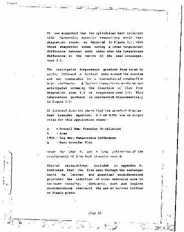
It was suggested that the cylindrical heat exchanger with diagonally opposite connections would have stagnation zones, as depicted in Figure 3.1, with these stagnation zones having a lower temperature difference between each other than the temperature difference at the centre of the heat exchanger, zone 3.0.
The anticipated temperature gradient from inlet to outlet followed a helical path around the annulus and was comparable to a conventional counterflow heat exchanger. A further temperature gradient was anticipated crossing the direction of flow from stagnation zone 1.0 to stagnation zone 2.0. Thia temperature gradient is represented diagrammaticaly in Figure 3,2.
It followed from the above that th'$ standard Fourier heat transfer equation, Q = uA toiTD, was no longer valid for this application where:-
u = Overall Heat Transfer Co-efficient
LMTD = Log Mean Temperature Difference Q = Heat Transfer Flux
since the LMTD is not a true reflection of the relationship of Q to heat transfer area A.
Initial oalculatinns, included in Appendix A, indicated that the flow rate through the exchanger would be laminar and practical considerations precluded the reduction of cross sectional area to increase velocity. , Similarly, cost and hygiene considerations restrictd the use of helical baffles or dimple plate.

Heated Milk at 72"C to regenerator
Warmed Milk — I---'— i to Heater
bo
Milk Out at 15'C
Figure 3.1 Anticipated Flow, Regenerative Exchanger
Page 34

This laminar flow would inhibit heat transfer and promote stagnation zones.
.th was necessary to determine a dimensionleas factor • C , being a function of cylinder diameter, height, internal spacing and flow rate, which might be applied to the overall heat transfer equation as Q = GuA LMTD, The application of this factor would correct the LMTD for this specific application and hence verify the .area A necessary for the effective heat exchange required or, conversely to determine the maximum flow rate achievable from a practicably sized unit.
The determination of the correlation between the various elements comprising the factor 'C' for cylinders of different proportions and flow rates was outside the scope of this report.

Temperature
Cumulative Heat Exchanger Area
Figure 3.2 Regenerator: Anticipated Temperature Gradient

CHAPTER 4
MODEL DESIGN
4.1 General
This chapter describes the model constructed and the limitations of the model and the test rig taed.
4.2 Model Construction
The model was constructed to verify the principles involved in the conceptual design. To undertake this verification it was only necessary to simulate flow through the first annulus of the proposed design. The model as such, was a s/.igle annulus around the centrally heated core. The use of a single annulus , facilitated the fitting of transparent observation panels and simplified sealing of the annulus ends.
Various materials for construction were considered and in the event 0,0mm rolled galvanised mild steel sheets were used, with 3,0mm high impact plastic panels and soldered joints and fittings.
Heating of the water 1 i the central core was provided by two 3,OkW immersion heaters with thermostats adjustable from 40*C to 756C. Holes were drilled through the centres of the panels and at other strategic points' in the annulus through which the bulbs of mercury and glass thermometers could be fitted. A hydrauHc leak test was undertaken in the works before the holes in the annulus were drilled.

The central core was fitted with a valved drain
The test rig was fitted with a means of controlled dye injection to the water at the inlet of the model and for test purposes water was passed through the annulus with the contents of the central core being
The dimensions of tha model were generally in accordance with Figure 4.1. The leading dimensions of 1 200mm high ■ and 600mm diameter were thoseproposed for a production unit and suited to standard plate sizes with the minimum of cutting and wastage.
The diameter of the inner cylinder was 375mm thus leaving an annular width of 12,5mm. This gap was maintained by the use of spacing lugs at the top and base of the inner cylinder, positioned to avoid interference with the flow. The thin material necessitated a number of swages to the inner and outer shells, but these swages were located opposite each other so as not to cause restrictions.
A further smaller cylinder was positioned so as to take up approximately 2/3 of the inner cylinder water volume and • thus reduce both the weight and heating time of the appliance.
The inner cylinder was painted white behind the observation panels order that discoloration onthe introduction of blue dye could be more easily observed. Thermometer mounting brackets wereattached to the outside shell in the positione indicated in Figure 4.2 and ultimately thermometers sealed into the holes with flexible sealant.

The dosing of dye was effected with a valved dosing assembly as indicated in Figure 5.1 and comprising a clear water by pass valve (red) and two dosing valves (yellow) with a removable glass container for the dye cubes.
4.3 Limitations
The method of construction introduced certain inconsistencies jn the annular dimension which would not occur in a production model having machined end plates to correctly locate the shells.
The concept design proposed an external heat source, storage hank and hot water pump instead of the static heated water used in the model. The former would have been more f-^sily monitored? while the latter was much cheaper to manufacture.
In the experiment water temperatures were checked at the top and bottom of the heated core and an arithmetic mean determined for use in calculations.
The heat balance of the model was such that the heat lost by the immersion heaters was gained by the working fluid in the annulus. The extent of this gain was studied both in convection assisted and convection opposed flow. In relation to the concept design, convection assisted flow in the model approximated parallel flow, and convection opposed flow approximated counter flow.
In temperature detection, economics determined that mercury in glass thermometers be used in place of multi-point electronic instruments and it was considered that the specified accuracy of within 0,5*C was adequate for the experiment.

□
utrm 4.1 v-'i’tivn and elevation of Model
Figure 4.2 Location and Numbers of 'jtiermometers
* 3^— «

The purchase of an SABS certified thermometer for calibration purposes was conaj.- .ired and re iected. CaJ ibvation of twelve thermometers was carried out against the thirteenth thermometer which waa found to ha"'? a mean f'f the range of readings of all the thermometers at ambient temperature.
The Ricketts Blue dye cubes used i.n the test had the disadvantage thnt they do not dissolve uniformly thus making the use of an accurate comparator impossible, Also, irregular dissolution of the cubes brought about changes in density of the dyed liquid.

CHAPTER 5
TEST OF MODEL
5.1 General
This chapter contains the consolidat resultsobtained from the experiments descri. -d under section 5.2, arid derives certain mathematicalrelationships from these results. Theserelationships a r e . then compared with established theoretical or experimental data given by earlier workers in thiu field.
The test results for flow in the annuluo are collated in the following forma
Convection assisted with central core heated. Convection opposed with central core heated.Bottom flow connection with central core unheated.Top flow connection with.central core unheated.
for each of the following
Sequence of panel Corruption, Tables Cl, C2 Sequence of panel clearing. Tables C3, C4 Time taken to corrupt from zero base, Tables C5, C6 Time taken to clear from zero base, Tables C7, C8 Time taken to corrupt per panel, Tables C9, CIO Time taken to clear per panel, Tables Cll, Cl2 Temperature distribution. Figures Cl to C5
From the experimental data it was possible to make certain observations on flow patterns, cycle times

and retention times and then to investigate the £ollowingi-
5.1.1 Flow State
The Reynolds Number and flow con-Ktiori were confirmed for the specific annular gap and diameter of the experimental model.
5.1.2 Decay Time
An expression for the decay time of the clearing of a panel was derived and the residual concentration after a given period calculated.
5.1.3 Transfer Area
The theoretical heat transfer areas for both parallel and counter flow modes were calculated.
5.1.4 LMTD Factor
LMTD factors for the experimental model in both convention assisted and convection opposed flow modes were derived.
5.1.5 Nusselt Number
The Nusselt Number for the experimental model was derived and the actual and theoretical heat transfer co-effioents compared.
5.1.6 Comparison with Established Data
The mathematical relationships derived from the experimental results were compared with other relationships documented in Volume II of the

HEDH'a ’ for convection assisted and convection opposed laminar flow. The validity of these alternatives in this application ia discussed.
5.2 Test Method
The arrangement of the test rig and the method of testing are outlined in the following sections.
5.2.1 Thermometers
The thirteen mercury in glass thermometers were checked at an ambient temperature of approximately 13,5‘C. The thermometer reading 13,3'c was chosen as a standard since it was the approximate mean of all the thermometer readings. The deviations of the other twelve against this thermometer are tabulated in Appendix B.
The thermometers were numbered with No 1 being the standard thermometer and deviations were againcompared in a warm water bath at approximately 40'C.
£ ,>.2 Annular Thickness
The thickness of the annular space was measured with a vernier at each thermometer entry point and the average found to be 12,1mm. These measurements are tabulated in Appendix B.
5.2.3 Test Rig
The test • rig was connected as shown in Figure 5.1 for convection assisted flow, the water supply being provided from a centrifugal pump maintained atconstant suction head by a reservoir. This was necessary as no mains water supply was available.

Flow rate was determined by recording the time taken for the discharge to fill a 4 litre container.
The discharge was taken through a glass jar against a white background to facilitate identification of the presence of any dye.
5.3 Procedure
Teats were undertaken to record the temperature distribution for given flow rates under stable conditions with the water heaters on. These wereboth for convection assisted flow as in Figure 5.1,and convection opposed flow with the connections reversed.
In each case, as shown m Figure 5.1, the red clear water valve was closed and yellow dye by-pass valves opened to observe, through the clear inspection panels, the rate and pattern of corruption of the anrtulus by the dye.
The time was recorded on the first entry of dye into each panel and again when each panel was full ofdye. The time at which dye was first observed inthe. discharge was also noted.
The tests were ;hen repeated with the yellow dyevalves closed and the red clear valve open. The time of decay of the dyed panels was recorded from the start of decay until the panels weresubstantially clear of dye. The time of clear discharge was also recorded.
The flow pattern through the annulus without theheaters on was observed and times recorded aspreviously.
Page 45

n
- M H ---- [-*— H---= Valves — —
iq — nDye Dosing
Timing
Figure 5.1.Test Rig with convection assisted flow
Page 46

Thia section comprises the Test Sheets numbered OX to 17 completed during the flow and temperature distribution tests and contained in Appendix B.
Significant observations made during the testing programme were as follows:-
With bottom feed and no primary heating, the flow was, as anticipated, generally diagonally helical with the appearance of stagnation zones at Panels 3
With top feed and no primary heating, the flow was vertically down from inlet to bottom of the annislus, with dye discharge occurring immediately after contamination of Panel 3 and before contamination of Panels 4 and 8 was complete.
With bottom feed and primary heating, the flow was convection assisted, and it was observed that the convection forces were such that they were predominant, causing the flow to be vertical fairly evenly distributed around the circumference. Convective clearing was ' such that stagnation zones did not occur. The temperature gradient was even.
With top feed and primary heating, the flow was convection opposed, resulting in a flow of entering cold water directly to the bottom of the annulus, with partial mixing and convective migration upwards. This resulted in an uneven temperature gradient with fluctuations and hot spots, clearing in this mode was difficult to assess due to the even and gradual convective diffusion of the clear water upwards through Panels 4, 8 and 9. This flowpattern is depicted in Figure 5.2.

5.4 Observations on Test Results
In general terms the test results appearedsufficiently consistent, given that the experimental equipment was basic by laboratory standards, and that problems were, experienced with only two operators attempting to accurately record therapidly changing results. For ease of reference Tables 05 to 012 have been averaged arithmetically to indicate mean readings and the associatedaccuracy of individual tests.
The nature of the test programme did not justifyexpanded discussion on statistical errormeasurement.
In certain cases, readings were missed throughinterruptions and difficulty was experienced in maintaining a consistent level visually at which a panel was declared to be 99,5% clear.
Uneven dissolution of the Rickets Blue Dye precluded the use of a test tube comparator as originally intended. In retrospect it would have been useful to have had a small sealed section of annulus containing clear water behind each observation panel, against which the adjacent liquid could have been compared.
The use of a stopwatch would have simplified time keeping rather than the cumulative method used with an ordinary clock.
In the top flow connection configurations, the discharge pipe had to be raised to empty above fcne height of the unit to ensure complete filling of the annulus. With a simple loop in the discharge pipe
Page 4r>

the syphoning effect tended to draw air into the annuJus through minor leaks.
Since the clearing of dye from panels tended towards asymptotic, with large changes of time occurring for very small changes in concentration, it wasreasonable to take the arithmetic average of results in each case and use these as a basis forcalculation.
5.4.1 Corruption and Decay Sequence
Tables Cl to C4 indicate the sequence with which the panels were corrupted by the introduction of dye, and cleared on the re-introduction of clear water.
In Table cl the sequence of corruption is the samefor both bottom and top f L jM connections. Thisappeared to have been caused by a slight density difference between the cold dyed water entering the top of the annu.lus and the water existing in the annulus. This density difference was assumed tohave been due to the inclusion of the denser dyematerial in the flow, possibly assisted by thermally induced currents in the antulus from ambient or solar gains. The occurrence, while noteworthy, is of no relevance to a milk flow condition.
Regrettably temperature gradients were not recorded where no primary water heating was applied.
The similarity of results in sequence of fillingshow the flow of entering cold water in convectionopposed mode directly to the bottom of the annulus ah Panel 3, with the separation of the convective rolls rising to corrupt Panels 4, 8 and 9, while in the convection assisted mode the corruption is
Page 49

horizontally even from th'j bottom up.
Comparable corruption in convection opposed flow would thus have been 9, 8, 4, 3 and this would be expected with a sufficient increase in mechanically induced flow rate. • It was noted that with bottom connection the flow tended to be helical at Panels 4
The sequence of clearing of panels with no heat, when compared with the similarities of the sequences of corruption, indicate that the primary cause of density difference was due to the inclusion of the dye, since the entering clear water more readily cleared to the top point of the annulus with the top
The same principle applies to the clearing with heat applied in convection opposed mode. The change in sequence of the results in convection opposed mode was ascribed ho a reduction in flow rate for Tests 15 and 17 with an associated possible predominance of convective forces. The denser dye material collected in Panel 3.
5.4.2 Time taken to Corrupt from Zero Base
Tables C5 and C6 indicate the average times for corruption from the start of each test.
Table C5 shows that, for conditions of no heat, cycle times of 8 minutes 12 seconds for bottom connection at a flow rate of 4,090 1/m and 7 minutes 33 seconds for a top connection and flow rate of 3,356 1/m are similar. The slight differenceindicating that the denser dyed water clears more readily when the flow is in a downward direction.
Page 50

Table C6 compares -the filling ti- .rom a zero base for opposed flows.
From an inspection of Tables C5 and C6 , the even horizontal corruption of convection assisted flow, and the rapid corruption of Panel 3 in convection opposed flow is apparent. The convective migration upwards from the bottom, first to Panel 4 and then to Panels 0 and • 9 can also be noted. These flow patterns are indicated in Figure 5.2.
The average cycle tiroes are similar in bot:h cages at approxii<, 'tely 5 minutes 30 secondu each.
5.4.3 Time Taken to Clear from Zero Base
Tables C7 and CB indicate the average times for clearing from the start of each test.
Table C8 compares the clearing tiroes from zero base for covection assisted and convection opposed flows. The significarce of these results is in the cycle times where convection assisted mode is on average 3 minutes 15 seconds less than the convection opposed mode, with cycle peaks having a difference of 6 minutes 25 seconds.
With pasteurisation in mind this indicates the advantage of employing convection assisted flow irl a milk to milk regenerative heat exchanger. Both cycle times are well within the accepted maximum cooling time of one hour to reach 7*C. This is normal for batch pasteurisers, but the project design is required only to cool to 15*C, with sub-cooling to 7*C taking place in an external tank. However, even taking this into account the cycle times are acceptably short.

Convection Assisted
Convection Opposed
Figure 5.2 Flow Patterns

5.4.4 Times to Corrupt and Clear per Panel
Tables C9 to C12 indicate the times taken to fully corrupt and to fully clear each panel under various flow conditions.
The relevance of these results is in theinvestigation of retention times at panels having different temperatures, particularly those that would occur in U i milk to milk regenerative heat exchanger.
Under these circumstances Panels 4 and 6 would be those most likely to be at a mean temperature conducive to the propagation of residual bacteria and these retention times of 9 minutes 45 seconds and 7 minutes 04 seconds for clearing in convection assist nti mode are within acceptable limits based on a linear cooling rate of 1*C per minute and thus approximately 10 minutes to cool from 45"C to 35'C.
Assessment of the value of the maximum retention time per panel was made in conjunction with the average cycle time, to obtain a true reflection of the suitabi.lty of the proposed method for pasteurisation.
In any event the ultimate test is in the quality of milk finally produced when standard quality control measures are applied.
The theoretical concentration of original milk retained after a given period can be calculated using a decay equation and this is discussed later in this chapter.

5.4.5 Temperature Distribution
A comparison of the actual temperature distributions for convection assisted flow, being bottom entry parallel flow and convection opposed flow, being top entry counter flow ■ are shown in Figures Cl and C2. The data in each case was recorded for 3 tests having similar flow rates so that the average temperature could be taken at any point.
The horizontal, diagonal and vertical temperature gradients are represented graphically in Figures C3, C4 and C5. Using existing correlations it is possible to calculate, from Figures C2 and C2, the theoretical heat transfer area required for the actual heat transferred under the test conditions. From this the correction factors applicable in each case can be calculated.
The graphical representations in Figures C3, C4 and C5 show clearly the even temperature distribution of convection assisted flow when compared to convection opposed flow. The horizontal temperature gradient for convection opposed flow in Figure C3 between points 10 and 9 demonstrates the result of convective migration upwards in rolls, similar to those found by Stork & Mul3em<B>, even though the main stream is downwards. This is highlighted further in the diagonal and vertical gradients shown in Figure C4 and C5 which figures also indicate the effect of cooling in the flow between mid point and discharge.
In each experiment the thermostats on the immersion heaters were set at 70’C and as such never switched off. This had the advantage that the heat input to the core was constant and not cyclical for

calculation purposes. However, it had thedisadvantage that the control cycle for annular discharge temperature, when operating about a thermostat set point in the primary heating water,could not be evaluated. The annular gap of 25,0mmin the primary water ve'isel was assumed to besufficiently wide to approximate an infinite vessel for the priuary heat source.
5.5 Determination of Plow Condition
The flow is shown t,o be laminar with a ReynoldsNumber of 141 at a flow rate of 3,545 1/m and anaverage annular gap of 12,Intro. Calculations are contained in appendix D.
5.6 Derivation of Decay Time
The calculation in appendix E indicates that theprobable residual concentration of original milk in a pane] would be 0,00001% after 30 minutes. While this is an approximation, it does indicate the level of dilution within the risk period for propagation of residual bacteria in the outflowing pasteurised milk. It can reasonably be assumed that the level of contamination with this dilution would not affect the commercial acceptability of the milk.
5.7 Derivation of LMTD Factor
The calculations in Appendix F show the LMTD forconvection assisted flow to be 5,77eC and forconvection opposed flow to be 14,20*C.
According to Korn1'*1, in conditions where the viscosity is in the region of one centlpoise (10-* Ns/m*) at the cold terminal and the temperature

range is below 40‘C with a difference of below 10'C. The nrlthmnkio me,in of khe inlet nml ouklektemperatures can be used to evaluate fluidproperties.
For convection assisted flow, the above criteria apply and the arithmetic mean temperature in the annuluR can be taken from Figure C2 as :-
T mean = 13 H 23,45'C
For convection assisted parallel flow, the flow rate from Figure Cl was 3,157 1/min or 109,42 kg/h for a temperature rise from 13‘C to 33,9‘C.
Thun taking c*. 6 23,45'C = 4100 J/kg K accordingto ASHRAB13’
Q = mcnA T= 189,42kg/h x 4100 x <33,9 - 13)- 16547,70 kJ/h = 4,5966 kW
and for convection opposed counter flow, the flow rate from Figure C2 was 3,025 1/min or 181,40 kg/h for a temperature rise from 13'C to 21,5'C.
Q = 1,7911 kW
The heat transfer surface available in each case is identical as:-
A = Annulus ID x it x length- 2,171 m"

Neglecting radial conduction due to the smalldifferr-nrr in radii, then the heat transfer to the annulus is:-
Q = uA LMTD
or more specifically, allowing for changes in film co-efficient for convection assisted and convection opposed flows then:-
= uA C LMTD
where c is a dimensionless factor specifically related to the performance of the test model under certain parameters of flow condition, flow rate and temperature gradient. C also serves as a measure of the efficiency of the usage of the heat exchanger surface available, when compared with an ideal theoretical exchanger having the same 'u' value and LMTD.
Thuo for convection assisted flow;-
4596,6 W = uC x 2,171 x 5,77
C 366>34and for convection opposed flow:-
1791,1 W = uC x 2,171 x 14,2
thus, if it is considered that for an ideal theoretical heat exchanger C = 1,0, then decreasing

values of C are associated with falling efficiency
C assisted = C opposed
= 6,3167 C opposed
Assuming the galvanising of the heat transfer surface to be 0,075 mm thick and
Resistivity R = ^
k for zinc = 112 W/m Kk for steel = 45 W/m Kthermal resistance of zinc:-
thermal resistance of steel:-
Fouling factors are not to be considered as a production unit would be cleaned between each 4 hour
It can then be assumed that the resistance of the annulus inner wall is so low that it can beneglected and the value of 'u'can be based on surface co-efficients h.- and h„e only, thus:-

Since the experimental apparatus approximates, in convection assisted flow, two vertical flat plates, the correlation suggested by ASHRAE Fundamentals Vol I')??'3 ’ Section 2.12 Table 5 for naturalconvection can be used as followsi-
Nu « 0,56 (Gr pr ) ° •.ZB
This being applicable for laminar flow with (Gr Pr) between .!04 and 10s .
Calculations included in Appendix G indicate
The Grashof Number:- Gr = 2,226100 x 10s
The Prandtl Number at 23,45'C:- Pr = 6,405
The value of (Gr Pr) then becomes:- (Gr Pr) = J.,4258221 x 10?
which is s 10® and thus within, the limits of the correlation:-
Nu = 0,56 (Gr Pr)0'*8
= 34,412
and
Page 59

34,412 x 0,6
]
HIj t!|
= 417 W/m’K
This compares reasonably with the experimentally derived overall heat transfer oft-
UC = 366,94 W/m*K
The value of 'h' calculated, is equal to the overall transfer co-efficient 'u' since the LMTD was used to compute the Grashof Number instead of the mean wall and annular fluid temperatures.
The value of 'C* can be calculated for convection assisted parallel flow from:-
uC = 366,94 W/ro’K
u = 417 W/m’K
C = — = 0,879952 417
and for convection opposed eounterflow:-
where 524 W/m’K is the value computed using the Grashof number corrected for an LMTD of 14,27'C.
Both values relative to the correlation:-
Page 60
O

Nu = 0,56 (Gr Pr>a -!k0
If, however, a direct application of the LhfD were required without the use of a ' C factor, then a suitable correlation for the teat modex can be derived as follows:- .
h = 366,94 W/m*K
366,94 x 0,0494
30,21 = K (Gr Pr)'°'aB where 'K' ie a constant
Thus for the test model Nu = 0,491626 (Gr Pr>°'aaat 200 litres per hour in convection assisted mode.
Assuming then that the wall resistance is negligible and the surface resistances on either side of the wall are equal, then front:-
u = where h„ = hni. = h„0
and for convection assisted flow
Page 61

hM = 2 x 366,94 = 733,9 W/m’K
5.8 Comparison with Alternative Correlations
5.8.1 Sieder Tate
On the assumption that the flow through the annulus is laminar forced convection, then both Kern*41 and ASHRAE'3’ propose the Sieder Tate relationship:-
For the experimental model the value of
= 6,2070
which is very much less than the actual value oft-
Nu = 34,412
This correlation is alt,o proposed in theAPV (Pty) Ltd Heat Exchange Handbook'3 ' with the clarification that for the term:-

The exponent 'tV is a function of plate type varying between 0,1 and 0,2 while the constant of 1,86 can vary between 1,86 and 4,5 depending on the plate
clearly in the experimental model, the value of the constant would appear to be closer to 10,0 if the correlation were to be valid.
5.8.2 Heat Exchanger Handbook
The HEDH13 * expands this evaluation in sections 3,7,4 and 3,7,5 as follows:
Based on normally experienced flow through a plate exchanger, the flow would be expected to be laminar
and turbulent at:-
Re i 1000
It states further that the transition area between these values of Re ie difficult to predict without accurate testing ami lies between plate heatexchanger and flat plate theory.
it proposes that for flow in this region the heat transfer can be calculated by interpolation between the laminar value of:-

and turbulent of
Nu = 0, 2 (Re) 0' 6,'Prc>'4
for values of * 1 1 between 0,7 - 2,0m and D„between 4,0 and 7,0mm with an 1/w aspect ratio of more than 1,8.
To compare these two values for Pr = 6,405 aiv' Re at both 1000 and 10, then critical rtvsni'lt numbers
Hu = 42,84 Nu = 2,476and by interpolation for Re == 141
which is also invalid for the test model.
5.8.3 Cheremisinoff
It is proposed in Chapter 10 of Heat Transfer Equipmentts' by Cheremisinoff, that for spiral plate heat exchangersi-
0=,G
where D = the spiral dia and G = mass velocity

= specific heat
which, when calculated for the test model gives more realistic value of
h = 200 W/m4K
Hu = 16,5
However, this is still half the correct value.
5.0.4 Pohlhausen
It is proposed by Pohlhausen in HEDH'3section 2.5.1 that for parallel plates
where Pe is the Peolet Ndmber Pe = Re Pvand S is the equivalent diameter then:-
Nu = 12,6
Page 65

5.8.5 Stephan
For annular ducts the HEDH’3’ gives the f' correlation developed by Stephan £or:-
0,1 5 Pr S 10=0 S d,./d„ S 1,0Re S 2 300 A
, " . " 0,19EPe(dh/’<]°'eNu Nu_+ | , | lf0+0ill7!pe(dh/1)lo,46?
Using the chart in the HEDH'3 y of Nu- against di./de , Nu- was ' taken as 4,7 and £(di,/d«,)calculated fromi-
Nt.\ = 7,06
which is invalid for the test model.
5.8.6 Martinelli
For free convection in annuli, Martinelli, in HBDiI,a>, derived the following correlation:-
0,0919 AF Gr Pr
where A = +1,0 for convection assisted flow
and n = -1,0 for convection opposed flow
and F is evaluated from a graph as a function of

1/4 (Ped/1> where 1E” becomes asymptotic at a value of approximately 0,05.
The equation yields Nu = 8,2 for convection assisted flow and a negative Nu when the Grar.hof Number was corrected for the convection opposed LMTD. Clearly this is an invalid solution for this experiment and HEDH,a> dons suggest that the relaHnnsihlp should be used with care.
However, it is also suggested in HEDH‘a>, that the effects o* the free convection could increase the rate of heat transfer to a value of three or four times that of the fox'oed convection alone, and this would appear to be borne out by the Hus»selt Numbers derived from various correlations in this section.
5.9 degenerative Heat Exchanger
rased on a derived value €or 'u' of 3F6,94 W/maK, the area required for the regenerative milk to milk heat exchanger can be calculated approximately, assuming a cold fluid entering temperature of 4*C and a pasteruised milk leaving temperature of 15*C, with a uniform temperature difference of ll'C.
If losses are ignored then the heat lost by the warm fluid equals the heat gained by the cold fluid.
The heat lost by the warm flu = in cooling from the pasteurisation temperature of 72‘C down to t5"C is:-
Q = mc„/\T= 189 x 4100 x (72 - 15)= 10 773 kJ/h = 12 528 J/s

Q •= uA I.MTI)
1252(1 = 366,94 A 11
A = 3,10 m* being the surface area required forregeneration.
The available heat transfer area in one pass of the annulus is 2,1 m s.
5.10 Summary and Conclusions
The experimental process has established some clearly defined conclusions relative to the original project proposal and cast some doubt on the validity of certain established correlations when used in the test application.
5.10.1 Concept
It is concluded that the original concept design with the central annulus of the pasteuriser in a convection opposed counter flow mode would not work, due to the unexpectedly high influence of convective forces at low flow rates. However, in the convection assisted parallel flow mode, the concept of an annular heat exchanger with heated centralcore :is valid.
5.10.2 Stagnation Zones
The stagnation zones as originally envisaged in the concept design do not appear in the convectionassisted parallel flow mode and the dilution rate of residual milk would be such that the risk ofbacterial propagation in the pasteurised milk would not present a hazard.
Page 68

5.10.3 Practicability
The surface area envisaged for the regenerative section in the concept design was inadequate and a commercial prototype would have to have e double annulus in order to increase the heat transfer area.
Certainly, practical ' modifications such as corrugating the heat transfer surface could be introduced to enhance the heat transfer rate and area, but within the. terms of design reference for simplicity and ease of cleaning, it is preferable to have a double annulus.
5.10.4 Mathematical Relationships
It has been shown that the relationship:-
Nu = 0,491G26(Gr p,•>«>«==
is valid for the test model at the flow rate of approximately 200 1/h. Since this correlation isindependent of Reynolds Number, it will also be valid for the regeneration exchanger with a revised Grashof Number.
It has also been shown that if the standard correlation of :-
Nu = 0,56 (Or pr)0 -3'"
were used to calculate the heat transfer co-efficient then a dimensionless factor of :-
C = 0,079952
should be applied to the LMTD when calculating the

area required in the convection assisted flow mode.
5.10.5 Existing Data
Comparison with the existing experimental data of others, indicates that correlations which include the Reynolds Number are less likely to be accurate than those which are based on the Rrashof Number.
Presumably this is because the effect of natural, free convection distorts the relationships at low flow rates and values of Reynolds Number. This would also account for the invalidation of the Martinelli relationship, where a higher value of Reynolds Number would have yielded more realistic
The HEDH'**, cautions the reader to exercise care in the use of the Martinelli equation but does not give the limiting criteria within which the equation can be reasonably applied. It is suggested that some relationship between Reynolds Number and buoyancy forces are these limiting criteria.
5.10.6 Temperature Distribution
It has been shown experimentally that the temperature gradients through the annulus are evenly distributed in convection assisted parallel flow, and very irregular in convection opposed counterflow.

CHAPTER 6
PROTOTYPE DESIGN
6.1 General
This chapter outlines the design and manufacturing concepts for a prototype milk pasteuriser based on the findings of previous experimental work. The final arrangement of the pasteuriser is shown in Figure 6.1.
6.2 Shells
It was deduced in section 5.9 that a heat transfer area of 3,10m' is required for the regeneration section of the heat exchanger. Assuming that the height of the exchanger is fixed at 1 200mm bystandard plate size, then a mean annular diameterfor half the area required would be 411mm, andtaking an annular gap Of 12,5mm then the outside annulus would be 417,25mm, and the inside 404,75mm. However, allowing a 10% margin of error toaccommodate the effects- of possible over-heating, then the surface area of each annulus becomes 1,705m', and the mean becomes 450,2mm diameter, making an outside shell of 450,45mm. For simplicity of manufacture and taking into account the surface requirements of the heating section, this value is taken as 500mm, thus:-
outside annulus diameter = 500mmsecond annulus diameter - 475mmthird annulus diameter = 450mm

fourth annulus diameter 425mm
This conpletes the regeneration heat exchanger. The milk input is between the second and third annuli and the milk output between the first and second and third and fourth annuli.
If the fifth annulus, being the final heating section, follows a similar spacing, then its diameter would be 400mm. However, there is a strong case to have HD£ 1,2m for the heating shells so that the two shells could be made from one sheet of1 200mm x 2 400mm. .
Thus the outer heating cylinder can be 395mm diameter and the inner hot water cylinder 370mm diameter, both being cut from a single sheet without wastage.
Assuming a milk leaving temperature from the regeneration sections of 61'C, the temperature rise in the heating section will be 72*c - 61'C = ll’c and the heat input required, assuming a specific heat of 4100 J/kg K and flow 200 I/h.
Q = m C p A T» 200 x 4100 x 11 = 9 196 kJ/h = 2 559 J/s
Thus, for a heat transfer rate of 366,94 W/m’K and an inner annular area of 1,395m*:-

I--------
I l R e * a y P a n e l j 1
Figure 6.1 General Arrangement of Pasteur.t
2&x

The I.MTD can be manipulated by adjustment of the thermostats in the case of fixed heaters, or with forced circulation hot water at four times the milk flow rate, the temperature fall in the water would be about 3 ‘C, thus having an entering temperature of approximately 76°C • and a leaving temperature
(76-61) - (73-72)Then LMTD = -------- — ---------
’ Lnl5
This difference of 1'C at the pasteurised milk leaving point would be ideal for an optimum control condition of approximately 0,5'C.
The shells would be manufactured from 304 grade stainless steel 0,9mm thick in a standard 2b finish with one longitudinal weld.
6.3 End Plates
End plates are to be manufactured from food quality polyethylene, an attractive milky white material, easily machined and resistant to temperatures up to 120‘c. The material is heat weldable for fully sealed piping connections and an end plate of 25mm thick and 600mm diameter will not easily deform when tightened against the annuli.
The nr\A plates are to be machined with concentric grooves having centre lines of the diameters of the

annul! and sufficient clearance to enable the annul! to be earily located. The grooves would each have a gasket manufactured of food quality rubber forming a moderately compressible seal at each end of the annuli. The space between each pair of grooves would be drilled and tapped, or heat welded, with a suitable 10mm nominal bore connection and the bottom plate would be drilled and tapped for the fitting of the three electric heaters and drain. The end plates would have an outside diameter of 600mm, thus allowing an overlap of 50mm all round for the fitting of four tie rods on the outside of the annulii between the end plates with which to draw up the ends on the annuli. The bottom end plate would be fitted with four adjustable feet.
6.4 Holding Tube
The purpose of the holding tube is to ensure that all particles of milk entering from the heating section of the pasteuriser at 72*0, remain at that temperature for a period of at least 15 secondsbefore cooling commences. Based on a flow rate of 250 1/h, the maximum envisaged for the project, anda vertical holding tube of 1 200mm long, then the velocity necessary for a 15 second pass would be:-
ii'.T o oo ' "'O'*"
This would necessitate a pipe of 33,23mm diameter. However, taking into consideration the pipeworkleading into the holding tube, which in itself would form an extension of the holding tube, thecommercial size of 32mm nominal bore could beselected. The diameter should not be excessive as this would allow too much cooling and also in the

vertical position would allow separation of the flow pattern due to reduction in mechanically induced velocity with a proportional increase in the significance of convection forces. The holding tube would be connected with bottom entry to ensure even convection assisted flow. Clearly this holding tube does not meet the criteria recommended by Kessler'7 ’in the DF Bulletin, but will suffice for this application.
6.5 Piping
All piping, in accordance with good practice, would be constructed from dairy tubing in 304 stainless steel. Piping would be fitted with adequate unions for easy dismantling to clean and, while a diameter of 10mm would theoretically be suitable, with a velocity of 0,5 m/s and a pressure drop of 420 Pa/m at 250 U h a practical minimum size for cleaning would be 15mm diameter. Entering and discharge piping would have to be higher than the heater exchangers in order to flood the annuli and pump. In practice the entering pipework would be connected to a high level balance tank and the discharge pipework would feed a pasteurised milk tank at approximately 2 500mm level. This is located forgravity filling of the bottling machine.
The layout of the pipework is generally as shown in Figure 6.1. Provision to be made in the pipework for drains and venting as required and a 0 C - 100‘c glass thermometer will be fitted in a pocket at the entrance to the holding tube.
6.6 Pump
The pump head can be calculated using the CIBSB13’

equivalent length method and the equivalent hydraulic diameter of the annul! as follows;-
From tables for thin wall copper piping to BS 3931.
The pressure drop .in a 10mm diameter pipe at 0,069 kg/s is 420 Pa with an equivalent length EL of 0,5. The pressure drop in a 15mm diameter pipe with an EL of 0,5 is 200 Pa/m. The pressure drop in the 32mm diameter holding tube is approximately 4 Pa/m with an BL of 1,0.
The pressure drop through the annuli having an equivalent diameter of 24,0mm can be taken from tables for 25mm pipe as 9,0 Pa/m with an EL of 0,9 for full flow and 4,0 Pa/m with an EL of 1,0 for the regeneration section where the flow is reduced.
Thus, assuming a total pipe length to the pasteurised milk tank of 20 metres, including the integral piping of the unit and assuming that the inlet to the pasteurised milk tank at a height of 3 500mm then:-
20,0m 15mm pipe at 200 Pa/m 4 000 Pa1,2m 32mm pipe at 4 Pa/m 5 Pa2,4m 25mm pipe at 9,0 Pa/m 22 Pa1,2m 25mm pipe at 4,0 Pa/m 5 Pa
10 bends at K = 0,0 EL = 0,5 900 Pa
Entry to Holding Tube at K = 0,7 EL = 0,5 70 PaExit for Holding Tube at K = 0,4 EL = 0,5 40 PaEntry to annul! at K = 0,3 EL = 0,5 126 PaExit for annuli at.K = 0,4 EL = 0,5 160 PaEntry from Tank at K = 0,4 EL = 0,5 40 PaExit to Tank at K = 1,0 EL = 0,5 100 Pa
Page 77

Total Frictional Resistance == 5 476 PaStatic hnad i« 3 SOOmm - 1 200mm or approximately 23 000 Pa.
The total pump head is then 23 000 Pa + 5 476 la 28 476 Pa, or 2,9 metres of water.
The pump selected is a Little Giant, 3 MD, single phase unit with hygienic magnetic drive, and easily dismantled polypropylene head. The motor would be2 000 r/m 112 W.
The pump would be mounted on a suitable baseattached to the feet of the pasteuriser.
6.7 Diversion valves
The proposed polysulfone air operated valves can be adapted for solenoid operation by the manufacture nf a suitable bracket and the modification of astandard Bucket 24 volt solenoid. The 15mm valves are manufactured in Isr&el by SAB AFIKIM for milking machines and meet all international food standards.
6.8 Assembly
The general arrangement of the pasteuriser is shown in Figure 6.1. Suitable brackets would be provided for the holding tube and balance tank and the feet would be adjustable. The pasteuriser could be cleaned in place by the use of a hot causticsolution in the balance tank circulated in diversion mode and later discharged to the pasteurised milk tank. To clean by dismantling, the four knurlednuts at the top of the end plute would be undone andthe top end plate lifted off after disconnection of the unions in the pipework. The annuli could then

be lifted off and cleaned individually, as could be end plates. The pasteuriser could then bereassembled in the reverse order.
6.9 Pasteuriser Control System
The control system is required to maintain the required milk pasteurising temperature and divert for reprocessing any milk leaving the heating section of the pasteuriser below that temperature.
The criteria require that milk must be heated to at least 72*C an d , held at that temperature for15 seconds. Should the pasteurising temperature fall below 72"C then the milk must be recycled.
The pasteurising temperature is measured after the hot water to milk heating section of the pasteuriser and before the holding tube. Measurement at this point vi'h the diversion valves located after the holding tube, effectively allows a 15 second safety margin. Any rise in temperature above 72‘G results in a proportional rise of unpleasant burnt flavour in the product which is'undesirable from a consumr- point of view.
There are various ready made controller/recnrders on the market that would meet the above requirements, but the intention of. this project is to develop a simple system of control, via a PC, so that a farmer could use his pasteurising facility alongside his other software for milking and feed control as part of an overall farming concept.
It i?5 envisaged that the printer of the PC will serve as the recording system required in terms of the Standard Milk By Laws *1>, and that the option

of using a PC will be more cost effective than a conbroiler/recorder bought off the shelf.
6.9.1 Control Parameters
The basic control cycle required for a milk pasteuriser is a simple proportional system of heat input to the primary heating water against rise or fall of milk temperature around a set point of 72*C. While not specified in the Milk By Laws<1>, it is generally.accepted, and reference can be nade to Chapter XI of the IPF Bulletin No 200'"", that the recording instrument should have a span of about 17eC. 7‘d of which should be either side of thePasteurising temperature in divisions of 0 ,5'C. In practice, commercial plants can control to 0,1’C, but this control accuracy is clearly related to the narrowness of the leaving temperature difference between heated milk and heated water.
In a system having forced circulation of the hot water at, say, four times the milk flow rate, the accuracy of control will be vastly superior. The simplicity of the plant proposed does however mean that there is unlikely to be any sudden ch either in flow rate or incoming milk temperature, so the possibility of needing rapid control response is minimised. With this in mind, and taking into account the experimental model tests, it is proposed to use a static water container as a primary heater, rather than forced circulation.
6.9.2 Process Control System
The diagramatic airat yemenk of the process control is as shown in Figure Hi.
Page 60

Valves X and Y are the 24 vo>t adenoid operated diversion and flow valves respectively, and lU, H= and Hg are? heating elements each 3kW 220 V. Hi to R4 are low voltage normally open relays for thr* computer output to 24 volt 1nberfanp.
T is a PT 100 thermocouple. Of the three heaters, Hi., Hs and liar Iti and II, are control heaters and H3 serves to provide additional input when starting from cold.
Bs and Rs are 24 volt/220 volt normally open relays for heater control. Each heater has an intergral overheat thermostat which would be set at. approximately 60°C to suit the temperature gradient of the primary heating water under stable flow conditions.
As a process technique, in common with other pasteurisers, water would be circulated through the system until the pasteurising temperature- is reached. The primary control requirements are depicted in Figure H2.
6.9.4 Logic Definition
The logic definition is outlined in Figures H3 and H4 which indicate the control logic and time logic respectively.
The time cycle has been taken as 10 seconds, since with a holding time of 15 seconds this frequency would ensure that diversion would take place before any milk having a lower temperature than Set Point reached the diversion valve.

6.9.5 Control Software
The logic defined in section 6.9.4 has been presented in a simple BASIC programme in Table Hi.
While this programme does not purport to be commercially acceptable software, it nevertheless serves to illustrate the type of simple programme that can be written for the control cycle. All variables such as set point, cycle times and intermediate switching levels are eaaxly adjustable in the software to facilitate the reduction of hunting; this being an inherent problem associated with the use of a static water supply.
The draft programme employs only simple programming techniques and assumes inputs readily available in a convenient form. In practice however, an analogue 1/0 Board such as the Dascon -1, manufactured by Metra Byte Corp has its own language symbols for inputs and outputs. For example MD% = mode, CH% = Channel No, DI0% “ A data 1/0 integer array. BASADR% = Base addresfl of DASCON 1 accessed.
For the purpose of this report the draft programme depicts th-' interpretation of the logic in terms acceptable to a PC, On production of a prototype pasteuriser a card will be custom built and the final prog>--mme developed around this card.
The software takes a time input, stores it, compares it every 10 seconds to current time and completes a control cycle of temperature checks and actions.
Every 60 seconds the programme initiates a PRINT of time and milk temperature also recording both a DIVERSION MODE and audible alarm on milk
Page 02

temperature fall
The subroutine in the programme, for simplicity, assumes a linear output of 4 - 20 mA from atemperature detector and converts this to atemperature reading in degrees centigrade.
This oversimplification of the input to the PC isintroduced to demonstrate the need for such aconversion in the final programme, the complexity ofwhich would depend on the type of card ultimately incorporated.
The programme would continue looping for the duration of the pasteurising run until the system were switched off and the flow manually diverted.

CHAPTER 7
SUMMARY OF CONCLUSIONS
7.1 General
The contents of this chapter summarise theconclusions outlined in each of the precedingchapters.
7.2 Validity
It has been shown experimentally that the original concept of a pasteuriser with a counter flow heating section, as depicted in Figure 1.1, is invalid due to the unexpectedly high role played by convective forces in mechanically induced laminar flowconditions. It has, however, been further shown that the concept of laminar flow milk pasteuriser, with an annular, convection assisted, heating section, as shown in Figure 6.1, is valid andinnovative.
7.3 Existing Data
From the literature survey, it was apparent that there is a dearth of works relating to heat transfer in concentric annuli, with either convection assisted r - convection opposed flow. Certain doubts have ber.i cast on the validity of existing equations. It is suggested that this area might offer scope for further research to establish the limits within which existing data can be applied and to develop further mathemetical relationships for
Page 84

practical application.
7.4 Experimental Data
Extensive experimental data was obtained Crom a series of teats carried out on a full size model of one annulus, with primary heating, manufactured for the project.
7.5 Stagnation
It has been shown that in the convection assisted mode, due to the even temperature gradients, the anticipated propagation of stagnation zones at risk temperatures is not likely to occur.
7.6 Heat Transfer
From experimental data, mathematical relationships have been derived for the heat transfer, namely
Nu = 0,491626 (Gr Pr)°'*=
or that a factor of 0,879952 shoulu be applied to the LMTD when using the Fourier equation.
The overall heat transfer co-efficient wasdetermined as 417 W/m'k.
The reader is referred to Chapter 5 for expanded conclusions.
7.7 Controls
The analysis in chapter 6 has shown that the concept of using a PC to control the milk pasteuriser and record the data is viable and in keeping with
Page 85

current trends in the farming industry. There is nodoubt, however, that the question of control systemstability has not been adequately addressed in the project report and will only be resolved throughexperiments ot, a prototype machine,
7.B Practical Application
The original concept has, as a result of the project research, been modified in three major ways. Theregeneration section has been doubled, the flow pattern in the heating section of the pasteuriser has been reversed from counter to parallel flow and the overall diameter of the pasteuriser has been reduced from 600mm to 500mm.
The design concepts are based on ease ofmanufacture, with maximum local content, avoid'ng the use of expensive imported plates, and with thesmall scale of daily milk throughput envisaged,practical considerations have taken nr=cedence over heat exchanger efficency.
7.9 Commercial Application
In the light of the project results a patentapplication has been filed, Appendix I refers, and commercial manufacture appears economically viable.
7.10 Summary
The writer is conscious that many areas of thedesign, such as film co-efficients, limiting conditions of validity, control stability andcorrelations relating to convection within theprimary heating medium, have not been fullyexplored. This has been firstly b e c a m e of the
Page 1)6

practical need to draw a lino somewhere in the research and secondly to limit the research to that necessary to validate commercial manufacture, while nevertheless Bntisfying the requirements of the six month project report.
Page 87

INITIAL CALCULATIONS
The conceptual calculations contained in this Appendix are presented uncorrected in their original form converted from imperial units.
Mass flow rate required 250kg/h.
Milk Specific Heat taken as 0,95 times that of
Regeneration Section; Milk to Milk.
Ti in 4,4'CT x out 50,0‘C approx
Heat rejected = Heat gained (Losses ignored)
Q = 250 x 0,95 x (72,2-21,1) x 1,163 = 14 009 J/s
at a mean temperature difference of 15,6 degC
based on 567,6 W/tn*K for concentric cylinders the Area t-
72,2‘C 21,1*C
Heating section; Water to Milk.
Milk out50,0‘C72,2‘C
Page 60

Heat tp.in • (72,2 - 50) x-0,95 x 250 x 1 , 1(55
» 6 131 J/a
Assume a water temperature rise of 5,6 degC and an arithmetic mean temperature difference under counterflow conditions of
AMTD ~ 73,91 * (73,9 “ 50)- 14,7 degC
and surface area required at 851,7 W/m’K (for serpentine plates).
A = 0,409m*
State of Flow
250 kg/h approximately 0,25m*/h
Assume gap between cylinders of 12,7mm Equivalent diameters = 2 *x 12,7mm
= 25,4mm
Assume 609,6mm > diameter inner cylinder. Then perimeter of ar.nulus is 1,915mm and
CSA = 0,0239m*
thus velocity = 0,00206 m/s
Viscosity of milk = 1,5 centipoise
He = 52,5 and Flow will be laminar
Page 89

AtPl tilNDrLX
TEST RESULTS
Annular Thickness
The following annular thicknesses were measured through thermometer pockets:-
Table B.l Annular Thickness
Pocket No Thickness
1
Discrepancies in dimensions appear to have arisen during manufacture, apart from No 6 which was caused through damage in transit.

Thermometer Corrections
Table B.2 Thermometer Corrections
ThermometerNumber Ambient Correction T!3V Correction
13,3 0,0 42,3 0,013,0 +0,3 42,2 +0,113,1 *0,2 42,2 +0,113,7 -0,4 42,2 *0,213,1 *0,2 42,6 -0,313,1 42,3 0,013,7 -0,4 42,6 "U,312,9 + 0.4 41,7 + 0 613,0 *0,3 42,0 + 0rl12,9 42,0 +0,313,9 -0,6 42,1 +0,213,5 -0,2 42,0 + 0,313,4 -0,1 42,3 0,0
Thermometer No 1 taken as base thermometer with zero correction in terms of Chapter 5, section 5.2.1.

TEST REPORT
Test So.! 01_____Date: 7/07/00Time: 12.06.00 'Ambient Temp.t 14*CStatus: Convection 0$6dridd/AsBiated/MiZPrimary Water Heatings Yes/MdFlow Measurement: 4 litres 63 secs
Therms. Dye StatusNo. Dig c Time Time
Open D,. 16 50." 55.103 13.0 Panel : • v; i'O.e 50.30 No 3 Olv).1 a> Clear 56.332 14,5 Panel Ni ti U lb 3 Clear 17 01.25
15,0 Panel No 4 visi.id - No 4 Start a? Clear 56.204 21.9 Panel No 4 full i2.*0 hn 4 Clrvir 58.25
24,5 Panel No 0 -visfble 31', 20 No 8 Start to CJmr 57.1523,0 Panel NO S f.Ml I 53.% No 8 Clear 02.20
7 24,0 Panel No 1' vislh,’,? 53.22 No 9 Start to Clear!50.0025,5 Panel 9 fni.l No 9 Clear C/.00
9 29,020,0 Dye Discharge Visible 54.30 Dye Disciiai^e Clear 0,V30
1.1 33,012 30,1 "lose Dye 55.1013 —
Notes: Time change 16.00.00 to 17.00.00

TEST REPORT
Teat No.: 02_____Dates 7/07/88Times 17.10.00Ambient Temp.s 14*C______Statuss Convection Og^dddd/Ascisted/Mil Primary Water Heatings Yes/WdFlow Measurement $ 4 litres 62 secs
Therms. rye statusNo. Deg Time
Open Dye 17 Open Water 22.3533,5 Panel No 3 visible No 3 Start to Clear 24.2014,0 Panel No 3 full No 3 Clear
3 14,5 Panel No 4 visible No 4 Start to Clear4 26,8 Panel No 4 full No 4 Clear 32.10s 23,4 Panel No 8 visible No 8 start to Clear 25.206 22,8 Panel No 8 full No 8 Clear 33.557 23,6 Panel No 9 visible No 9 Start to Clear8 24,2 Panel No 9 full No 9 clear
27,927,0 Dye Discharge Visible Dye Discharge Clear31,3
12 36,5 Close Dye13 —
“

TEST REPORT
Test No.: 03_____
Date: 12/07/80Time: 14.00.00Ambient Temp.: ____ 13*C______Status: Convection 0;#dddd/AddidKd«l/Nil Primary Mater Heating: Yes/NoFlow Measurement: 4 litres 5? secs
Therms. Dye StatusNo. Deg Time
Open Dye 14 Open water1 Panel No 3 visible No 3 Start to Clear 23.572 Panel No 3 full No 3 Clear 55.173 Panel No 4 visible No 4 Start to Clear 18.004 Panel No 4 full No 4 Clear 50.305 Panel No 8 visible No 0 Start to Clear6 Panel No 8 full , No 0 Clear
Panel No 9 visible No 9 Start to ClearPanel No 9 full No 9 Clear 35.18
Dye Discharge Visible Dye Discharge Clear 40.131112 Close Dye13
Notes: Panel 9 half full when discharge started blue. Flow is laminar spiral. To clear flow is vertical spiral. Clearing is 9/G/4/3.

TEST REPORT
Test No.i 04Date: 12/07/88Time: 14.S8.00Ambient Temp.: 13'C______Status: Convection 0;#dddd/*ddidKdd/Nil Primary Hater Heating: Yd^/NoFlow Measurement: 4 litres 59 secs
Therms. Dye statusNo. Deg C Time Time
Open Dye 15 Open Water1 Panel,No 3 visible No 3 Start to Clear2 Panel No 3 full No 3 Clear3 Panel No 4 visible No 4 Start to Clear4 Panel No 4 full No 4 Clear5 Panel No 8 visible No 8 Start to clear6 Panel No 8 full No 8 Clear
Panel No 9 visible No 9 Start to Clear
8 Panel No 9 full No 9 Clear
Dye Discharge Visible Dye Discharge Clear
Close Dye
Notes: One cube of dye only. Flow is vertical to Panel 9

TEST REPORT
Test No.: 05_____Date: 12/07/68Time: 15.44.00Ambient Temp.; 13*C______Status: Convection 0##dddd/*ddldKdd/Nil Primary Water Heating: Ydd/NoFlow Measurements 4 litres 58___ secs
Thoms. Dye StatusDeg C Tine
Open Dye Open Water 55.50Panel No 3 visible No 3 Start to Clear 01.30
? Panel No 3 full No 3 Clear 30.143 Panel No 4 visible No 4 Start to Clear 56.434 Panel No 4 full No 4 clear5 Panel No 0 visible No 8 Start to Clear
Panel No 8 full No 8 ClearPanel No 9 visible No 9 Start to Clear 56.19Panel No 9 fall No 9 Clear 12.27
Dye Discharge Visible Dye Discharge Clear 13.16
Close Dye
Notes: Two dye cubes used. 15.50.27 photograph of Panel 4 was taken, then photograph of 8.
Page 96

TEST REPORT
Test No.: 06_____Date: 13/07/30Time: 12.56.00Ambient Temp.: 14*C______Status: Convection Assisted/NilPrimary Water Heatings Yes/NdFlow Measurement:___ 4___ litres 60 secs
Therms. Dye- StatusNo. 0*9 C
Open Dye 13 Open Water1 11,5 Panel No 3 visible No 3 Start to Clear
13,0 Panel No 3 full No 3 Clear13.5 Panel No 4 visible No 4 Start to Clear20,0 Panel No 4 full No 4 Clear
5 22,0 Panel No 8 visible No 8 Start to Clear6 21,5 Panel No 8 full So 0 Clear 24.447 22,0 Panel No 9 visible No 9 Start to Clear 17.230 23,0 Panel No 9 full No 9 Clear 27.19
27,026,0 Dye Discharge visible Dye Discharge Clear 27.0930,036,0 Clise Dye20,0
Notes: Two dye cubes used. Flow is liiminer/ vertical.

TEST REPORT
Test No.! 07_____Date: 13/07/00Time: 13.40.00 •Ambient Temp.i 14‘CStatus: Convection tigSjidddd/Assisted/MZZPrimary Water Heating: Yes/MdFlow Measurement: 4 litres 76 secs
Therms. Dye StatusDrag C Time Time
Open Dye 14 04.00 Open Water12,5 Panel No 3 visible tfc> 3 Start to Clear
2 13,8 Panel No 3 full No 3 Clear3 14,0 Panel No 4 visible No 4 Start to Clear4 23,3 Panel No 4 full — No 4 Clear5 26,0 Panel No 0 visible No 8 Start to Clear6 24,5 Panel. No 8 full — No 8 Clear7 26,5 Panel No 9 visible — No 9 Start to Cleara 27,0 Pannl No 9 full — No 9 Clear
30,030,5 Dye Discharge visible Dye Discharge Clear
ii 34,532 37,5 Close Dye13 21,2
Notes: Test aborted - dye problems. Restarted 14.04.00 Telephone! 14.09.16 all panels full and blue discharge.

TEST REPORT
Test No.: OSDate; 13/07/SBTime; 14.26.00 :Ambient Temp.; 15‘C______Status: Convection 0g5^eii<6d/Assisted/N£Z Primary Water Heating: Yea/MdPlow Measurement: 4 litres 76 secs
Therms. Dye Statusueg c Time
Open Dye 14 Open Water 38.151.3,0 Panel No j visible No 3 Start to Clear 39.53
2 15,0 Panel No 3 full 31.59 No 3 clear 52.4817,0 Panel No 4 visible 32.14 No 4 Start to Clear22,8 Panel No 4 full 34.10 No 4 Clear24,5 Panel No 8 visible No 8 Start to Cl^ar 42.2224,0 Panel No B full No 8 Clear 48.1826,0 Panel No 9 visible No 9 Start to Clear 43.5326,2 Panel Zfo 9 full No 9 Clear 55.1420,030,5 Dye Discharge Visible Dye Discharge Clear33,537,5 Close Dye20,5
Notes: Plow is vertical/laminar. Panel 0 late call 14.42.22 Dye solution on lew speed test is unsatisfactory

TEST REPORT
Test No.i 09_____Date: 13/07/00Time: , J .01.00Ambient Temp.: '15dC_______Status: Convection fltfgSdddd/Assieted/MiZ Primary Water Heating: Yes/NdPlow Measurement: 4 litres 76 secs
Therms. Dye StatusNo. Time
Open Dye 14 Open WaterPanel No 3 visible NO 3 Start- 1 o ClearPanel No 3 full No 3 Clear
16,0 Panel No 4 visible 03.00 No 4 Start to Clear4 23,0 Panel No 4 full No 4 Clear5 25,2 Panel No 8 visible No 6 Start to Clear
24,2 Panel Ho 8 full No 8 Clear26,5 Panel No 9 visible 06.52 No 9 Start to Clear 13.2327,5 Panel No 9 full No 9 Clear 27.5029,230,0 Dye Discharge Visible Dye Discharge clear 24.16
37,0 Close Dye23,0
Notes: convection forces dye spearation into vertical stings. (Additional dye) Better results
Page 100

TEST REPORT
Test No.: 10_____Date: 14/07/08Times 10.55.00 ___Ambient Temp.s ll'C______Status; Convection (%6dddd/Add(dKdd/Nil Primary Water Heatings Ydff/NoFlow Measurements 4 litres 59 secs
Therms. Dye StatusNo. Deg C Time Time
Open Dye 10 Open Water1 Panel No 3 visible No 3 Start to Clear 06.292 Panel No 3. full 59.22 No 3 «" sr 11.29
Panel No 4 visible 57.20 No 4 Start to Clear 05.39Panel No 4 full 59.33 No 4 Clear 10.29Panel No 0 visible No 0 Start to Clear 05.24Panel No 8 full No 8 Clear
7 Panel No 9 visible 02.44 No 9 Start to Clear
8 Panel No 9 full 04.17 No 9 Clear 10.52
10 Dye Discharge Visible 59.00 Dye Discharge Clear 12.541112 Close Dye 04.45
Notes; No leaks from dye system.
Page 101

TEST REPORT
Test No.: 11_____Date: 14/07/80Times 11.37.00__ .Ambient Temp.i 12*c______Status: Convection e gSgSrieSel/Jlrfriidtitfd/Nil Primary Water Heating: Ydd/NoPlow Measurenent: 4 litres 70/74 secs
Therms. Dye StatusDeg C Time Time
Open Dye 11 Open WaterPanel No 3 visible NO 3 Start to ClearPanel No 3 full No 3 Clear
3 Panel No 4 visible 40.17 No 4 Start to ClearPanel No 4 full 41.33 No 4 Clear
5 Panel No 8 visible 39.45 No 8 Start to Clear6 Panel No 8 full 45.00 No 8 Clear7 Panel No 9 visible 44.30 No 9 Start to Clear
8 Panel No 9 full 46.30 No 9 Clear
Ilyc Discharge Visible 41.15 Dye Discharge Clear1112 Close Dye 46.5013
Notes: Panel 9 verbally no corruption 11.44.00. Flow is from 10 straight down to 3. Dye discharge dark blue. Dye line drops horizontally. Leak from dye system.

•-..-Ay-
TEST REPORT
Test No.! 12 Date: 14/07/anTimes 12.33.00 ,Ambient Temp.s 13*C______Status: convection Qlg:]ddddd/XddidKdd/Nil Primary Water Heating: Ydd/NoPlow Measurements 4_____ litres 87 secs
Therms. Dye StatusNo. Deg C Time Time
Cpen Dye 12 Open Water1 Panel No 3 visible No 3 Start to Clear
Panel No 3 full No 3 ClearPanel No 4 visible ' 6to 4 Start to clearPanel No 4 full No 4 Clear
5 Panel No Q visible No 8 Start to Clear6 Panel No 8 full No 0 Clear
Panel No 9 visible 30.27 No 9 Start to clear
8 Panel No 9 full 39.21 No 9 Clear
Dye Discharge visible 34.40 Dye Discharge Clear
Close Dye 40.00
Notes: Leak from dye system.
Page 103

TEST REPORT
Teat No.: 13_____Dates 14/07/80Titue: 14.48.00Ambient Temp.: ____ 13.5°CStatus: Convection 0##dddd/AddldKdd/Nil Primary Water Heatings i«Sj!/NoFlow Measurements 4 litres 70 secs
Therms. Dye Status
No- Deg C Time TimeOpen Dye 14 Open Water 02.00
1 21,8 Panel No 3 visible No 3 Start to Clear23,5 panel No 3 full No 3 Clear22,3 Panel No 4 visible No 4 Start to Clear26,5 Panel No 4 full No 4 Clear
5 20,2 Panel No 8 visible No 8 Start to Clear 03.326 28,0 panel No 8 full No 8 Clear 13.587 23,0 panel No 9 visible No 9 Start to Clear 05.27
27,2 panel No 9 full No 9 Clear9 31,0
13,0 Dye Disctiarge Visible Dye Discharge Clear11 13,512 39,3 Close Dye13 20,5
Notes: Convection is vertical - esp Panel 4. Flow is 10/3 Convection is 4/8/9. 3.07.30 even defused blue. General defusion remains. Thermometer No 7 fluctuates +- 1'C
Page 104

TEST REPORT
Test No.: ____14Date: 14/07/88Times 15.24.00 .Ambient Temp.t 14*C______Statusi Convection Opposed/RddidKdd/WiI Primary Water Heating: Yes 'M«JPlow Measurement: 4 litres 74 secs
Therms. Dye StatusNo. Deg C Time Time
Dj\u 15 Open Water1 22,0 Panel No 3 visible No 3 Start to Clear2 Panel No 3 full No 3 Clear3 Panel No 4 visible 30.40 No 4 Start to Clear
Panel No 4 full 31.35 No 4 Clear28,5 Panel No 8 visible 31.30 No 8 Start to clear
6 29,0 Panel No 8 full 32.27 No 8 Clear7 24,0 Panel No 9 visible 32.43 No 9 Start to Clear8 Panel No 9 full 34.55 No 9 Clear 52,599 31,010 14,0 Dye Discharge Visible 31.28 Dye Discharge Clear 47.4911 13,012 39,5 Close Dye
29,0Notes: Thermometer No flucuates +-1°C. Convection began at 15.31.20. At 15.38.55 photograph, general light blue. At 15.39.52 punp/dye system/very even difusion. When 'clear' there was slight defusion of dye - Test 13 too. Valve seeting for Tests 13 6 14 as per unheated test and no leaks from dye system.
Page 105

TEST REPORT
Teat No.: 15Date: 14/07/88___Time: 15.59.00 .Ambient Temp.: 13‘C______Status: Convection Opposed/Addfdtdd/Nfl Primary Water Heating: Y e s / WFlow Measurement: 4 litres 79 secs
Therms. Dye statusNo. Deg C Time
Open Dye ■ 16 05.00 Open Water 11.301 21,5 Panel No 3 visible 05.24 No 3 Start to clear 12.40
23,2 Panel No 3 full 05.35 No 3 clear ? 20.5021,5 Panel No 4 visible 05.50 No 4 Start to clear26,8 Panel No 4 full 06.59 No 4 Clear27,5 Panel No 8 visible No 8 Start to Clear20,0 Panel No 8 full No 8 Clear ?
7 23,0 Panel No 9 visible No 9 Start to Clear0 26,0 Panel No 9 full No 9 Clear9 30,0
14,2 Dye Discharge Visible Dye Discharge Clear13,039,0 Close Dye 11.3020,2
Notes: Tbemmeter No 7 fluctuates +- 1*C. At 16.06.14 photograph of Panel 4. Rolls - strings - convective. System set at maximum flow available.
Page 106

TEST REPORT
Test No.: 16_____D a t e s 14/07/00Time s ____ 16.35.00Ambient Temp.: 12*c______Status*. Convection Opposed/AddidKdd/WiI Primary Water Heatings Yes/MelPlow Measurements 4 litres 79 secs
Therms. Eye StatusDeg C Time Time
Open Dye 16 43.00 Open Water21,5 Panel No 3 visible No 3 start to clear
2 23,5 Panel No 3 full No 3 clear3 21,5 Panel Nn 4 visible •• 43.40 No 4 Start to Clear 49.404 26,0 Panel No 4 full 44,51 No 4 Clear 00.40s 27,5 Panel No 8 visible 43.55 No 6 Start to Clear6 27,5 Panel No 8 full No 0 Clear
21,0 Panel No 9 visible No 9 Start to clear0 21,5 Panel No 9 full 48.08 No 9 Clear
30,513,2 Dye Discharge Visible 46.00 Dye Discharge Clear13,530,3 Close Eye 48.3026,2
Notes: Maximum flow available. Themametet No 3 fluctuates s— ,5"C and Thermometer No 7 +- 1*0. Flew dkwn then rising. Convection is spiral left/right. Discharge deep blue, panels light blue. M l clearing slowly, fairly evenly.

TEST REPORT
Test No.i 17_____Dates 14/07/00Time: 17.00.00 • •Ambient Temp.: ____ 11*C______Status: Convection Opposed/Addldtdd/Mff Primary Water Heating: Xes/MdPlow Measurement: 4 i t ™ sees
Therms. Dye StatusDeg C Time Time
Open Dye 17 Open Water21.5 Panel No 3 visible No 3 Start to Clear
2 22.0 Panel No 3 full No 3 Clear3 Panel No 4 visible No 4 Start to clear4 Panel No 4 full No 4 Clear5 Panel No 0 visible No 8 Start to Clear6 Panel No 8 full No 6 Clear7 20.0 Panel No 9 visible No 9 Start to Clear
26.5 Panel No 9 full No 9 Clear9 30.0
13.0 Rye Discharge Visible Dye Discharge Clear
Close Dye
Holes: Thermometer No 7 .fluctuates +- 1"C. Vertical convection slightly left to right. Convection strands between 1 and 1,5cm apart, and Ion wide. 17.19.39 air leak.
Page 108

7VI?E»BISIDXX C
CONSOLIDATED TEST RESULTS
Table Cl Sequence, of Panels Filled
Bottom Flow Connection - No Heat
Top Flow Connection - No Heat
Page' 109

Table C2 Sequence of Panels Pilled
Convection Assisted
Convection Opposed

Table C3 Sequence of Panels Cleared
Bottom plow Connection.- So Heat
TEST No PANEL No PANEL No PANEL No PANEL No
9 8 49 8 3
5 9 8 4 3
Top Flow Connection - No Heat
Page 111

Sequence of Panels Cleared
Convection Assisted
Conviction Opposed

Tobin C5 Tlm« Tnkrm for Fillin') from S Wo tlnnr
Bottom Clow Connection - No Heat.
TBSTKo
PMBI, 3 M m 4 n m i PABBl 9 C1CL8 n wt t i i t S t a r t
n in -s e c » " -= = = * i i - a e c e io - e e c l in - s e c i i n - aee l i n - i s c 1 /e
3 18-15 4,167
< OB-SI 4 ,067
5 0»-31 1 ,137
M R M B 01-30 4,090
Top Flow Connection - No Heat
t u n 3 M m 4 P/lBEI. 6 PAHBl 9
F in ish S t a r t P in is b S U r t
■ l l - H T = i«-«e= l i t
00-45 01-52 01-50 03-53 4 .067
01-41 ? M 7 06-00 07-30 3 ,243
08-1? 11-13 00-46 05-27 2 ,756
AVBBiOB 50-42 01-43 01-5! i2- j a 14-58 3 ,156
Page 113

Table C6 Time Taken for Filling from Zero Base
Convection Assisted
r m »Mlltl 3 MIU t MWS!- 1 P1HBL « 07018 nw
Emit felt.b-secnir-Se=sin-iOTaln-sec 8in-=M .1. * •in-fee
i 0O-3i 3,100
2 00-33 ie-11 1,0000B-3B 05-13 06-05 1,000
7 00-30 ... ... ... 3,15)
a 00-27 02-H 06-10 3,157
9 00-25 02-00 07-27 3,15)IVBiUlOE 00-31 01-05 3,515
Convection Opposed
mThPA8BL 3 PAS86 1 PASBt, 0 PAHBL 9 Cl COB PM*
Start iiiieb Start finish Start Finish Start finishals-sM lli-IN itwie
01-15sin-sec nin-eecsin-secsin-sec 1/s
13 00-25 00-15 01-25 3,12811 00-20 01-10 0i-3O 02-27 3,113n 06-21 00-50 01-55 01-50 03-03 3,03716 00-25 00-10 01-51 00-55 02-31 03-03 05-10 05-00 3,017
17 00-20 02-05 02-36 02-50 01-10 3,000AVBMG8 60-26 01-35 01-51 02-10 03-03 05-21 3,119

Table c7 Time Taken to Clear from Zero Base
Bottom Flow Connection No Heat
mu.n m 3 PSBKi 4 nm s run» cress Ml
Start finish Start finish■ii-iM .h-M
3 «-n 81-40 03-10 1,86305-4J 31-il 01-33 11-25 4,063
5 SMS 34-24 01-53 02-10 4,133m m im 31-M 4,091
Top Flow Connection - No Honk
pmt, 3 PAHEL 4 'PAm 0 PAVS8 9 FLOSfinish Start Finish Start finishnh-BK sin-sec.in.secpin-sec■U-Ific*in-SMnin-SKinii-ssc Sin
10 01-44 06-44 05-44 80-39 05-13 06-0? 06-44 4,06311 62-41 04-23 00-56 (3-20 06-50 3,24312
AVRSAGS02-43 03-43 02-03 06-30. 81-09 04-40 2,35602-25 02 06 61-46 05-32 10-54 3,356
Page 115

Table C8 Time Taken to Clear from Zero Base
Convection Assisted
TEST*,r u n 3 H I U 4 m m r M U UCLB
Finish Start Start Finish■li-nc
.01-0501-45
6 00-38
7 09-00
ei 00-50 93-13
flVEMOR 00-58 U-U 02-45
Convection Opposed
Page 116

Table C9 Time to Corrupt per Panel
Convection Assisted
TiST PABBL3 MSBL « P1NRL 8 PMBL 9lin-aea ain-^ iln-sa;
1 00-05 00-43 3,600
5 02-10 3,999
f #H3 0M6 4,6697 01-37 -- - 3,157
i 01-31 O1-06 63-Ot 3,157
9 n-n 61-07 01-35 3,157AVBBHfiR ll-U 01-57 02-01 3,545
Convection Opposed
PiNBli 8 PSSEIi 9 PLOT

Table CIO Time Taken to corrupt per Panel
Bottom I'1 low Connection • - No Neat
m r phm, 1 mn 1 H H L 8 PHHIil, 9 PMK
i h - S M *in-sec l i s - s s c
SJ-08 4,067
< O H S 4,067
5 t H S
iVSSAGR 01-27 01-31 f , m
Top Flow Connection - No Heat
MUBi 3 PAHBE, < MEL 9»U-.to ■ ll-M Bin-seo '•in-sec
OMJ12-oej
2,758mmi ll-W $,35(
Page 118

Tabls Cll Time Taken to Clear per Panel
Convection Assisted
Convection Opposed
n o n
aln-iec 1/e
13 3,421
It 99-40 10-29 13-33 3,243
15 fl-lt 05-37 11-32 3,637
16 ^ 1 0- 5 4 11-66 12-43 3,037
1? 11-52 14-16 25-15 3,;oe
AVISMB 1 0 -U 11-28 14-0? 3,149

Figure ClCot-rooked Moan Tompnrnkiiron - Tenkn 7,(1 and 9
29,6'C
27,4‘C
24,3‘C
16,1‘C14,9'C
13,0*C
Temperature Distribution, Convection Assisted Flow
Page 121

Table Cl2 Time Taken fco Clear
Bottom Flow Connection - No Heat
TEST PAM 1 PAWBli 8 no*«,-=== ah-aee eh-=== ain-icc 1/e
3 21-20 1,667
! 1,06?
5 16-68 | 6,132
15-03 6,030
Top Flow Connection - No Heat

Figure C2Corrected Mean Temperatures - Tests 15,16 and 17
13,0‘C13,9*030,7‘C
25,4-C
21,0"C27 / 9*C
23,1'C '
Temperature Distribution, Convection Opposed Flow
Page 122

Ftgm-fi C3rior.izonkal Tfimpnraturo Gradientn
Thermometer NoConvection Assisted Flow
(10 k
Thermometer No
Convection Opposed Flow

Figurn C4Diagonal Temperature Gradients
Thermometer No
Convection Assisted Plow
Thermometer No
Convection Opposed Plow

Vertical Temperature tiradiontn
Thermometer No
Convection assisted Flow
Thermometer No
Convection Opposed Flow
Page 125

DETERMINATION OF PLOW CONDITION
The average annular gap was calculated at 12,1mm, Chapter 5, section 5.2.2 refers.
The outside diameter of the annulus was 600mm.
Thus inside diameter <600 - 24,2) = 575,6mm. Theequivalent diameter of the annulus is calculalod:-
I x flow area wetted perimeter
4%(D.* - Di»>
where D« and D& are the inner and outer diameters of the annulus
600* - 575,8’ --= 49,410 mn
taking absolute viscosity q£ water T' at 23'c
r = 0,000919 kg/m s
Page 126

and density of water ' at 23‘C
f = 995,9 kg/m*
Plow rate taken as 3,545 1/m
= 0,003545 m a/m
or = 0,000059 m 9/s
Flow area = — (D^* - D V )
= 0,022351 m s
and velocity 'v* = 0,0026397 m/a
. . . 2 ^
0,049410 x 0,0026397 x 995,9 “ 0,000919
The flow therefore is laminar.
Page 127
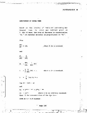
A IP IP IIIN O X X
DERIVATION OF DECAY TIME
Based on the results- of Table Cll and taking the longest time to clear per critical panel as9 min 45 secs, the rate of decrease in concentration 'Ci ' of residual material is proportional to 'Ci'.
dt ,where k is a constant
dCi 1 .
where c is a constant
log C i + c
log Ci = k(t - c)
Ci = Ae'*tt where A is an arbitary constantThus if the concentration of the dye is:-
100% at t ? 0,0 minutes

0,5% at t = 9,75 minutes
then at t r o
Ci = 100 = Ae<lc - 0 >
and at t = 9,75 minutes
Ci = 0,5 = Ae’*9'78
Ae** * °- = 200 Ae,,s'7a
100 * Ae<,e “ a>
100e<k ” 0> = 200 x lOOe1*9*75
100 = aOOOOe*9 -78
ek»,-7ti - o,005
e = (0,005* •t''9'7S *
and concentration at a time 't1 is given
= A [(0,005) lz9-',a,«
= A (0,005)te/9-7B
Ci = 100 (0,005)tez9'7a
Page 129

Thus coneentraticiv c£ original milk residual in p a n M ,ifi:nr 30 mlnuhns would be:-
Ci - 100 10,005)ao/9-:,s
= 100 {0,005) 3 ' 0"7S9
= 0,00001 %
Page 130

A P M I i i N D X X 17'
DERIVATION OF LMTD
Based on convection assisted flow and the tempera hires indicated in Figure cl.
/VT i
0,5 - 3,7
r 4'80,0317
For convection opposed . counterflow and using the data from Figure C2
25,96,7
19,21,3523
LMTD = 14,20‘C
I

A P w i s i m r x
DETERMINATION OF DIMENSIONLBSS GROUPS
tie Grashof Number
_ Daa f8gP/iTr " r»
and to determin' the co-efficient of expansion 8 between T& and T a:-
e ___ r*.- r*__2(2Ta - T*)(fi(a)
For water expanding from 23.4‘c with an LMTD of 5,77*C
«■ 997,5* ~ 995,9'2(5,77) 997,5 x 995,9
= 0,0002782/eC
Thus the Gr No based on the LMTD becomes:
_ 0,0494-- x 995,9* x 9,8 x 0,0002702 x 5,77r " 0.000919*
Page 132

D. = 0,0494 m
f » 995,9 kg/m3
g = 9,0m/s*
8 = 0,2702 x lQ-a/*C
/\T = LMTD
T = 919 x lO-^kg/m s
with all values taken at mean fluid temperature 23,45'C
Qr = 2,226108 x 10s
The Prandtl Number at 23,45‘C
4101,5 x 919 x 10-8 0,6
Pr = 6,405
c, = 4101,5 J/kg K
k = 0,6 W/m*l<
1. j.. ^

Draft Control Software
REM PASTEURER CONTROL CYCLEREM DAIRY ENGINEERING (SA>REM TEMPERATURE ACCESS TEMP PILEREM VALVE X OUTPUT CHANNEL 001REM VALVE Y OUTPUT CHANNEL 002REM HEATER 2 OUTPUT CHANNEL 003
160 REM HEATER 3 OUTPUT CHANNEL 004
LPRINT "ABC DAIRY CO - PASTEURISING RUN"LPRINT DATESLPRINT TIMESLET TIMES = ASDATA A TIMESLET BS '= VAL ASREAD TIMES
240 FOR TIMES = B$ TO BS * 00:01:00, STEP 00:00:10,
250 OPEN TEMP FILE260 INPUT 1$270 CLOSE TEMP FILE
200 REM SUB CONVERTS INPUT TO TEMPC lUB GOOOINPUT TSIF T$ > 70 THEN 360LPRINT "DIVERT MODE"OUT 001,003,004
r a W d

Table HI cont
340 REM AUDIBLE ALARM350 BEEP360 IF T$ 2 72 THEN 400370 OUT 001, 003380 LPRINT "DIVERT MODE"390 BEEP400 IF T$ 2 72,5 THEN 430410 REM MILK PLOW BEGINS420 OUT 002, 003430 OUT 002440 NEXT T1ME$450 STOP460 LPRINT 7$470 GOTO 20C
6000 FOR IS = 04 TO 20 STEP 0.1,6001 REM LINEAR THERMOCOUPLE ASSUMED6002 TS = M*I$ + 'C6003 REM M AND C THERMOCOUPLE CONSTANTS6004 RETURN
9999 END
Page 135
1 J

Figure HI General Arrangement of Control System
■»-
Page 136
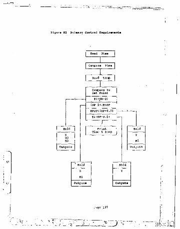
Figure H2 Primary control Requiremente
Read Time
Compare Time
(SP-2)<T<SPSPST<(SP+0,5)
Outputs Outputs

Figure H3 Temperature Control Cycle Logic
OutputOutput
Output
Output
Page 136

Figure H4 Time Control Cycle Logic
|Input T ime
Temp Cycle
Repeat Loop for Values B to (A+61)
Print Temp
Temp Cycle

PATENT REGISTRATION
page 140

D,M, KIRCH INC., Jolmnneihurg FormP.InEPunuc o f s o u t h affiicaPATENTS AC', 197BAPPLICATION FOR A PATENT AND ACKNOWLEDGEMENT OF RECEIPT(Section 30(1) — Regulation 22)The granl of a patent Is hereby requested by the undermentioned applicant on the basis ol Ihe presenl application tiled In duplicate.PATENT APPLICATION NO. APPLICANT’S OR AGENT'S REFERENCE=i||«i| H87U4S P/88/46828'
FULL NAMEfS) OF APPLICANT(S) |
71 CHRISTOPHER J/U4ES EARLYADDRESS(ES) OF APPLICANTS)
68A CHATTEN ROADGLENFERNESSMIDRAND
TfTLE OF INVENTION |
SA MILK PASTEURISER
TUB APPLICANT CLAIMS PRIORITY AS SET OUT ON THE ACCOMPANYING FORM P.2AODlfl%^P^m-%PLICArH)N NO, 21 01
THIS APPLICATION IS ACCOMPANIED BY:X A single copy ol a provMonalW&WIWIi*KK#MX(**#i*@* specillcallon ol 13 pages.X Drawings ol ) sheels.
Publication particulars and abstract (Form P.8 In duplicate).A copy ol Figure ol the drawings (II any) lor Ihe abstract, An assignment ol Invention,Certified priority documenl(s) (Stale number),Translation ol the priority document(s).An assignment ol priority rights,Acopyol the Form P.2 and Ihe specillcallon olS.A, Patent Application No. | 21 Ot |A declaration and power ol attorney on Form P.3 Request tor ante-dating of Form P.4 Requdbt tor classification on Form P.9
Patent Attorney Agent tor theAppllcanl(s)
ADDRESS FOR SERVICED.M. KISCK INC, Glencalrn Market Street Johannesburg
Se c e d e d ?'DvLOATE STAMP
ttvE!»TfcNTS

REFERENCES
1. Standard Milk - By-Laws. The Province of the Transvaal Official Gazette Extraordinary.Vol 213 11 Aug 1971.
2. Schlunder, E.v. ed. Heat Exchanger DesignHandbook. Vols. I-V.Hemisphere Publishing Corp 1982. *1RA.
3. Janssen, J.E. ASRRA? Guide 1977/80Vois I-IV. American Society of HeatingRefrigerating and Airconditioning Engineers INC. USA.
4. Kern, D.C. Process Heat Transfer. McGraw-Hill Book Co 1950. USA.
5 APV Co Heat Transfer Handbook, SecondEdition. APV Co USA.
6. Bhatia, M.V. & Cheremisinoff P.M. ProcessEquipment Series. Vol II. Heat TransferEquipment. Technomic Publishing Co INC. USA.
7. International Dairy Federation Bulletin No200 Monograph on Pasteurised MiiK 1986.IDF Belgium.
8. Stork, K. & Mullen V. Convection in Boxes. Journal of Fluid Mechanics. 1975, Vol 71, Pari 2, pp 231-240.
Page 142

CIBSB Guide to Current. Practice. Vols A-C 197C. Chartered Institution of BuildingServices Engineers. UK.
Cuttell, J.R. The HTST Plant. Dairy Industries Ltd .1940 UK.
Microsoft. IBM Basic. Second Edition1983, version 1.10. International Business Machines, USA.
Sanders, P.O. Interactive Computing InBasic, 1973., Butterworth & Co. U.K.
Bowman, R.A., Mueller, A.S. & Nagel, W.M.Journal of Heat Transfer. Transaction”May 1940 ASME USA.
Gebhart, B. Heat Transfer. McGraw-HillBook Co 1961 USA.
Rohsenow, W.M., Hartnett, J.P. & Ganic, E.8.Handbook of Heat Transfer Fundamentals.McGraw-Hill Bo o k Co 1985 USA.
Schenck, H. Heat Transfer Engineering.Longmans - Prentice Hall 1962 UK.
Roadhouse, C.L. & Henderson, J.L.The Market - Milk Industry. McGraw Hill Book Co 1950 USA.
Harvey, W.C. & Hill, H. Milk Production andControl. H K Lewis & Co 1967 USA.
Farrall, A.W. Dairy EngineeringJohn Wiley & Sons 1947

Lampert, L.M. Milk and Dairy ; r.fcg. Chemical Publishing Co NY l‘J47
Tulasidafif, T.N. 2008 Vlate HeatExchangers. Mysore Journal of Agricultural Sciences. Dep. of Agrici Eng. Univ. of Agric. Sci., Dharwad, Karnataka, India. 19C1
Wernimont, D. 4356 Choosing an asepticprocess. Food Engineering. 1983.
Marinoza, R.A. (Canada) 7509 Process andApparatus for Treating Food Products. United Skates Patent. 1905.
Aule, O. ; Tv <8*. • v 10 Methodfor heat -.-■i' i-nt of nic! the like.(Alfa-Lava • • ;-,05.
Miggens, A.L. Choosing on-farmpasteurising jJ.lJf" Dairy Farmer, 1P92. West of Sc,-! iarnl A-i - 'i> )i AUtihincrui vr.r 'JK.
de Vahl Daw tip o. arh^w.te, P.W. Nat^r-il Convection >»etiv-i-en Concentric VerticalCylii-iders.. l’h:,Bic» o.t Fluids. Supplement It
Cattell, G.S, Liquid Milk. DeveJypRi^ntii. in Heat Treatment Plant. Symposium 1981
Attwell, P. 7072 Small is beaut ful Food Industries of South Africa. ISfl'-V
Thomas, E.B, & Peters, W.r. 6082 (USA) (CBEPACO INC) Vertically extending heat exchanger. .1985.

Oairy Science Abstracts C.ft.B. International
shibing, S. Effect of Microwaves on Buffalo Milk. Egyptian J-iurnal of Dairy Science.

Author Early Christopher JamesName of thesis Design And Development Of A Milk Mini-pasteuriser. 1989
PUBLISHER:University of the Witwatersrand, Johannesburg ©2013LEGAL NOTICES:
Copyright Notice: All materials on the Univers i ty of the Witwate rs rand, Johannesburg L ibrary website are protected by South African copyright law and may not be distributed, transmitted, displayed, or otherwise published in any format, without the prior written permission of the copyright owner.
Disclaimer and Terms of Use: Provided that you maintain all copyright and other notices contained therein, you may download material (one machine readable copy and one print copy per page) for your personal and/or educational non-commercial use only.
The University of the Witwatersrand, Johannesburg, is not responsible for any errors or omissions and excludes any and all liability for any errors in or omissions from the information on the Library website.