Embed Size (px)
Citation preview

2018-Kettering-DUC
Design and Development of a Clean Diesel Snowmobile
Andrew Palardy, Alex Rath, Jinesh Shah Greg Davis
Kettering University
Abstract
Clean Diesel technology, in the form of a three cylinder engine featuring Common Rail Direct Injection, has been applied to a commercially available snowmobile. The goals of this effort include reducing exhaust and noise emissions to levels below the U.S National Parks Service (NPS) Best Available Technology (BAT) standard while maintaining or improving the utility of the snowmobile. A custom control system has been developed, and an aftertreatment system consisting of a Diesel Oxidation Catalyst (DOC), Diesel Particulate Filter (DPF), and urea-dosed Selective Catalytic Reduction (SCR) are used to combat emissions. All goals were achieved using cost effective technologies.
Innovation
While Kettering University has entered a Spark Ignition vehicle into the Challenge since the beginning, the team is in its second year competing in the Diesel Utility Class. This year, the team has focused on refining and optimizing the powertrain developed in 2017, improving emissions with a new aftertreatment system, and fixing open issues from last year.
Overall, Kettering has chosen to use the Mercedes-Benz OM660 ‘Smart Car’ Common Rail Direct Injection engine. A custom model based engine control system has been developed to allow flexibility in engine management and development of vehicle specific features. The control model is fully torque based, including a number of torque requestors and a torque arbiter to determine the
demand on the engine, and a combustion manager to coordinate combustion and emissions related parameters while achieving the demand torque. An injector driver box was designed and built to provide the required current waveform to the direct injectors.
While the initial control development was done for the 2017 season, the control model has been heavily expanded and improved based on feedback from the calibration process. New software features have been added to nearly every subsystem in support of more advanced after-treatment and combustion management. While a Diesel particulate filter was used in the past, the team encountered many problems with soot loading and the system was unable to regenerate the filter. The soot limiting and targeting software has been restructured to control a fuel to air ratio objective, better managing engine out soot emissions. The control system now
Figure 1: Mercedes-Benz OM660 Diesel Engine
Page ! of ! 1 14
02/19/2018

supports manually triggered particulate filter regenerations, as required for the particulate filter. The injection advance and rail pressure have also been recalibrated for better fuel consumption.
Traditionally, Diesel engines produce significantly more NOx emissions than other constituents. This mixture is difficult to catalyze. In addition, better attention to engine efficiency during combustion calibration for the 2018 entry increased NOx significantly while improving engine efficiency and soot output. To fight high NOx, a selective catalytic reduction (SCR) system was developed. SCR systems are capable of reducing NOx with high efficiency but require a reducing agent to be metered into the exhaust system. The SCR catalyst, urea supply system with freeze protection, and dosing control model are all new for 2018, and the design is detailed later in the paper.
As the OM660 engine was not designed for a snowmobile, many changes were required to the engine and chassis for packaging purposes. A new dry sump oil system was designed to improve oil pan packaging, and the cooling system was redesigned after numerous failures.
While not unusual for Kettering, strong attention has been paid to both engine and vehicle noise emissions. An exhaust silencer was designed to attenuate engine noise after the aftertreatment system, leaving enough packaging space for both catalyst modules. Additional noise enhancements have been added, with a strong focus on reducing radiated noise through chassis and body panels. All noise treatments are newly developed for the 2018 DUC entry.
Team Organization and Management
One of the key requirements for successful completion of all of the SAE Collegiate Design Series (CDS) is effective project management and team organization.
Team Organization
In a traditional company or organization there is a very structured approach to project management. Every employee has a job title and a specific set of job requirements. Timelines are set and processes are well defined for how a product should move from a set of requirements to a finished product.
While that approach has many potential advantages it was decided that that would not be the best approach for the Kettering Snowmobile team. Unlike a job at a corporation participation on the team is purely voluntary. Additionally, there are relatively few opportunities for gaining course credit or academic achievements, unlike some schools where their CDS programs are a formal part of their capstone courses. As such it is very difficult to have a ”traditional” team organization structure as students who are involved with the team do not have many tangible short term incentives to be very active on the team. Instead of the more traditional approach, we decided to operate using a ”Scrum” project management approach that is an application of agile project management principles.
In the Scrum approach the team management comes up with high level objectives for the team. Individuals on the team are given the high level objectives and then people who are interested in working on the project split up into a smaller subgroup to work on that project. That way they have a wide breadth of freedom to complete the objective in whatever manner they choose. Projects that are chosen are generally designed to be modular in nature, that way if a particular group is unable to complete the task they are working on, the sled is still functional or able to be reverted back to a previous design. This allows new and innovative solutions to problems be implemented quickly.
This type of team organization works well in teams that have several very dedicated members that are driven, self starters, and have good problem solving skills.
Page ! of ! 2 14
02/19/2018
Recruitment and Team Building
Recruitment of new team members is essential to keeping a team running and long term success. The Kettering team focuses on two main avenues of recruitment, the first is bringing in freshmen and new transfer students that are starting at Kettering. The second avenue is recruiting among students that are already a part of other SAE CDS competitions, such as Formula SAE and Baja SAE. Recruitment of students that are new to college has some benefits and challenges. There is generally a very steep learning curve for students that start early in their college career, however, getting students started early on allows time to for them to develop their skills and become very strong team members by the time they become upperclassmen. Recruiting from other SAE teams allows us to tap into the knowledge base, skills, and experiences that are gained from other competitions.
Specifications
The specifications for the 2018 Kettering University entry to the Diesel Utility class are presented below.
Table 1. Snowmobile specifications.
Design Objectives
The goals of the competition are to improve the emissions, fuel economy, and noise of a production snowmobile while maintaining or improving on performance. Kettering has gone beyond the competition minimums and set the following design goals for 2018:
1. Functional Diesel powertrain using modern Clean Diesel technology
2. Emissions level meeting or exceeding EPA Tier 4 Off-Road limits, which are significantly more stringent than the NPS BAT and EPA Snowmobile limits
3. Fuel economy exceeding 30 miles per gallon when traveling at 35 miles per hour
4. Sound pressure level meeting NPS BAT requirements, and pleasant sound quality during utility operation
5. Maintain dynamic performance appropriate for a utility snowmobile, with a focus on endurance and load capability over top speed
6. Maintain MSRP cost comparable to existing utility class sleds, including the Diesel engine
To achieve these goals, a 2016 Ski-Doo Tundra SE Sport Utility sled and Mercedes-Benz OM660
Snowmobile Model Ski-Doo Tundra SE
Model Year 2016
Track 137” Camso Cobra
Engine Model Mercedes-Benz OM660
Cylinder Configuration 3 In-Line
Fuel Biodiesel
Displacement 799cc
Compression Ratio 18:1
Peak Power 32kW @ 4200 RPM
Peak Torque 95 Nm @ 3600 RPM
Fuel System Type Common Rail
Fuel System Model Bosch CRS1 w/ CP1 Pump
Fuel System Pressure 1400 Bar
Engine Control Module Woodward MotoTron SECM-70
Engine Control Software Student Developed
Maximum Boost Pressure 280 kPa absolute
Muffler Absorptive
Aftertreatment - DOC/DPF Catalyst
Faurceia DOC + DPF from Volvo XC70 Periodic regeneration
Aftertreatment - SCR Catalyst
Faurceia catalyst from Fiat 500 Bosch supply system
Page ! of ! 3 14
02/19/2018

Common Rail Diesel engine were chosen by the Kettering team for 2018
Snowmobile Selection
When choosing the base snowmobile for the DUC entry, the primary consideration was the packaging volume available to the engine. After the engine, the snowmobile’s original acoustic properties were considered. It is known that the track length of a snowmobile has a large effect on the track noise, which represents a large portion of non-exhaust noise on a snowmobile [3]. For this reason, the shortest track length available in the utility segment was chosen. This combination resulted in the selection of the Ski-Doo Tundra SE. The Tundra was equipped with a Rotax 600 ACE engine, which was replaced with the Diesel engine. The Tundra also features a widened engine bay due to the Rev-RU suspension design compared to other Ski-Doo models, increasing the packaging volume available.
Engine Selection
The Kettering team chose a Diesel engine featuring a common rail direct injection system for the 2018 Challenge. Diesel engines show significant benefit in the utility market segment, where their high torque, towing capacity, reliability, and fuel efficiency overcome their disadvantages in weight and high end power. This combination is a perfect fit for a utility focused snowmobile like the Tundra.
The Diesel engine cycle is more efficient in practice than Otto or Miller cycle gasoline engines. Since Diesel engines do not inject fuel until combustion is desired, the compression ratio (and thermal efficiency of the combustion cycle) may be increased over Otto or Miller cycle engines as there is no chance of pre-ignition or knock. In addition, Diesel engines operate with excess air and do not require a throttle valve, reducing the pumping losses associated with light load operation of gasoline engines. For these reasons, Diesel engines are estimated to have a 15% reduction in greenhouse
gas emissions compared to their gasoline counterparts [1].
The Mercedes-Benz OM660 engine, used in the Smart Fortwo model 450, was chosen for its common rail injection system, all aluminum construction, and small size. Aluminum construction, common in automotive engines but significantly less common in Diesel industrial equipment, results in much lighter weight compared to iron engines. The substantial weight increase of a cast iron engine in a snowmobile would negatively impact maneuverability and dynamic performance. With an aluminum engine, the weight increase over the 600 ACE engine native to the Tundra is less than 50kg.
Unlike industrial small Diesel engines, which rely primarily on distributor style injection pumps, automotive engines feature common rail direct injection systems. These systems are fully electronically controlled, which provides significant flexibility to the engine calibrator to modify injection system parameters to balance performance and emissions. The common rail system featured on the OM660 uses a Bosch CRS1 system supporting up to 1400 bar injection pressures, and up to 4 injections per cycle. By comparison, a distributor style injection pump on a similarly sized engine may be capable of 600 bar pressure and a single injection per cycle. Higher injection pressures allow fuel to be delivered faster, allowing better control of the combustion rate for ideal emissions. Multiple injections per cycle allows the combustion rate to be shaped through software, reducing the initial pressure rise rate and further improving emissions. This also reduces the characteristic Diesel ‘clatter’, which is generated by the rapid pressure rise during the initial stages of combustion.
While not exclusively an advantage of common rail injection systems, they are inherently electronically controlled. The use of electronic torque control allows flexibility in scheduling fuel based on transient conditions. Many small engine distributor
Page ! of ! 4 14
02/19/2018

pumps do not feature boost compensators, and will inject significantly more fuel during tip-in transients than the engine can burn, resulting in soot formation. The use of electronic control allows software based soot limiting, as well as other software features to shape the engine operation based on environmental conditions such as air density. Finally, electronic control allows the driver’s pedal feel to be shaped through calibration based on non-engine conditions such as CVT ratio.
Engine Modifications
Figure 2: Garrett GT0632 Compressor Map
Turbocharger and Air Induction System
The OM660 engine in its native application has a turbocharger, however there was not any information regarding the flow characteristics of that turbocharger and the original turbocharger was not readily available. The power curve of the 2017 snowmobile was used to calculate the expected gas flow through the turbocharger at several points on
the engines operating range. This was compared with several turbochargers that have been used or considered by the Kettering team previously including a Garret MGT1238Z, MGT1446, GT1541V, and GT0632. It was desired to use a variable nozzle turbine (VNT) type turbocharger as that technology can help with improving engine transient response. The GT1541V was the only VNT type turbocharger that was available the Kettering team, however its compressor map was not well sized for the OM660. The GT0632 was ultimately chosen as the gas flow rates matched well with its compressor map.
The high boost pressures from a turbocharger can greatly increase the temperature of the air going into the engine. Cooler air is generally desired after engine startup as it increases the air density, and thus the maximum power possible. Additionally, it lowers the required boost pressure for the same air mass, reducing the pumping losses for a given air mass flow. The stock OM660 air to air intercooler was ultimately chosen as it packaged well in the snowmobile and was sized for the engine.
Exhaust and Aftertreatment
To treat undesirable exhaust emissions, a comprehensive aftertreatment strategy was developed. Due to the emissions make-up of Diesel engines, a single catalyst is unable to effetely treat all exhaust constituents. To treat all emissions properly, three types of catalysts are used. The first is a Diesel Oxidation Catalyst (DOC), which oxidizes hydrocarbons and carbon monoxide in the presence of excess oxygen. Dynamometer testing showed over 82% hydrocarbon and 99% carbon monoxide conversion efficiency. The second catalyst used is a Diesel Particulate Filter. This filter traps soot on the catalyst matrix, preventing it from exiting the tailpipe. The final catalyst is a Selective Catalytic Reduction (SCR) system, which reduces NOx in the presence of a reducing agent. Together, the total emissions of hydrocarbons (HC), carbon
Page ! of ! 5 14
02/19/2018

monoxide (CO), nitric oxides (NOx), and soot are greatly reduced at the tailpipe.
Diesel Particulate Filter and Oxidation Catalyst
Diesel Particulate Filters are designed to trap and store soot particles and prevent them from exiting the tailpipe. Periodically, the soot filter must be regenerated to fully oxidized into carbon dioxide. Some production systems are designed to regenerate continuously based on exhaust temperature alone, but these systems have lower soot capture efficiency compared to ‘full-flow’ filters. A Faurceia combined DOC + DPF assembly was chosen for its excellent soot capture efficiency and size appropriate for the small engine. The catalyst bricks are 1.7L for the DOC and 3.5L for the DPF monoliths. As the DPF is a ‘full-flow’ type, periodic regenerations are required. A new control model was developed to request fuel to be injected into the exhaust via post-injections, leading to oxidation in the DOC raising the temperature of both the DOC and DPF to the regeneration point.
The DOC efficiency was measured (see ‘Emissions Test Procedure’ for more information), and found to have a conversion efficiency of 82.6% for HC and 99.3% for CO. While instrumentation grade soot measurement was not available, accumulator type sensor results showed no measurable soot after the DPF in any mode, while soot was readily measured before the DPF under modes 1, 2, and 3.
Selective Catalytic Reduction
Stoichiometric gasoline engines are able to reduce NOx through a three-way (oxidation-reduction) catalyst, which is able to catalyze NOx into N2 in the presence of CO and HC in an oxygen-poor environment. As Diesel exhaust is oxygen-rich and the ratio of NOx to CO and HC is very high, it is not possible to catalyze NOx without an additional chemical process. An SCR system for mobile Diesel engines uses aqueous urea as the reducing agent, which decomposes into ammonia in the high temperature exhaust environment.
A Faurceia SCR catalyst was selected, and a urea dosing system was designed from off-the-shelf components along with custom control models to build a complete system. The SCR monolith has a volume of 2.2L, and the housing integrates an urea injection port, urea mixer, and temperature sensor.
The development of an SCR system presented a number of challenges, similar to the challenges limiting the use of SCR in automotive applications. Aqueous urea (sold as ‘Diesel Exhaust Fluid’ or ‘AdBlue’) has a freezing point of -11C, which may be a challenge in a snowmobile environment.
To provide the required urea pressure and flow, and resist freezing, a Bosch solenoid driven urea supply/return pump was selected. The pressure and temperature in the urea line is measured, and the pump is software controlled to maintain pressure. The urea supply system has been designed to thaw urea using engine coolant, inhibit dosing until the system is thawed, and purge the pump and lines of urea on shutdown. A urea capacity of 3L ensures the system does not need to be filled often.
Atomization of the urea injected into the exhaust system is of high importance, as the urea must decompose into ammonia in the high temperature exhaust environment before depositing onto the catalyst monolith. The catalyst-provided exhaust mixer is used to enhance urea mixing and provide surface area for the decomposition to occur. A Bosch air cooled urea injector was chosen due to its low cost and simple operation. To characterize the injector and pump, the injector and pump were tested together on a flow bench.
Silencer
The design of the muffler was focused on minimizing noise output while maintaining acceptable exhaust back-pressure. The team was able to achieve this goal by using a perforated tube and dented baffle design. The muffler consists of an aluminum outer shell, inlet tube baffling system, internal dented baffle, and fiberglass packing.
Page ! of ! 6 14
02/19/2018
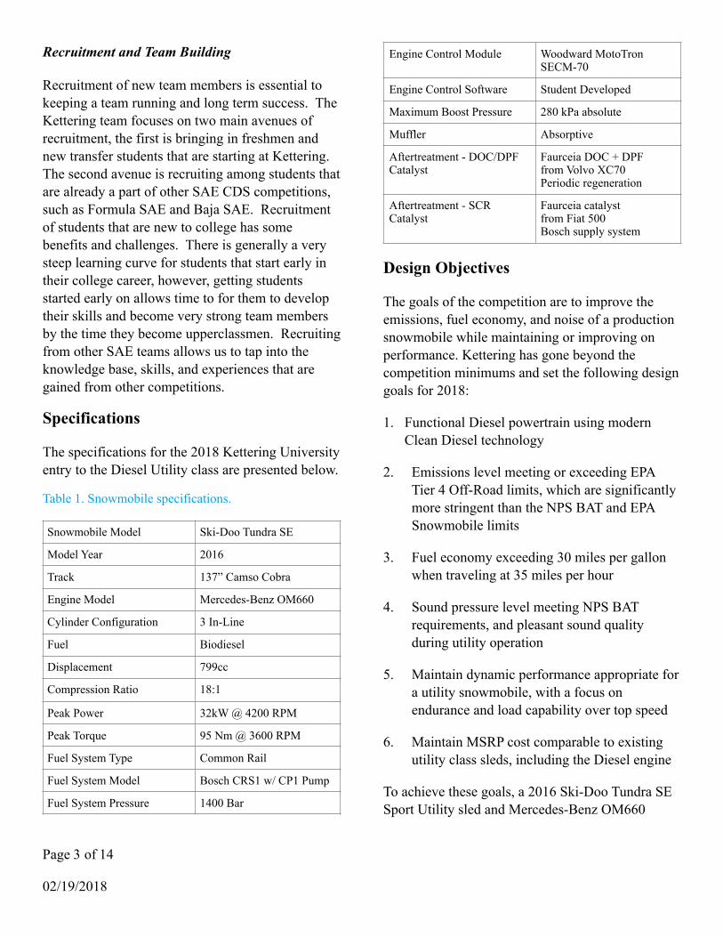
Testing showed a 34dB decrease in exhaust noise from the exhaust system without a muffler, at 0.5m from the outlet.
Figure 3: Dry Sump Oil Pan
Oil System
The OM660 engine required modifications to the oil pan to package in the snowmobile. To reduce the oil pan height and improve packaging without reducing oil volume, a dry sump oil system was designed. In a dry sump oil system, the oil pan is extremely shallow and not filled with oil. Oil which drips into the pan is quickly scavenged into a separate oil sump tank, which contains the bulk oil volume for the system.
Figure 4: Dry Sump Oil System Schematic
The new oil pan is made of 6061 billet aluminum due to the ease of fabrication for prototype use. Two electric scavenge pumps are used, each capable of
14 L/min of oil flow. The internal engine oil pump is used to provide pressure to the engine, drawing from the oil reservoir instead of the pan. The new oil sump tank is made of
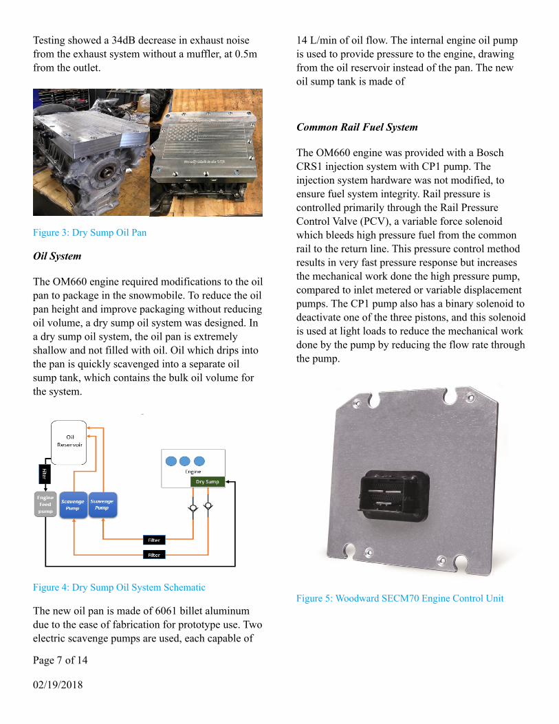
Common Rail Fuel System
The OM660 engine was provided with a Bosch CRS1 injection system with CP1 pump. The injection system hardware was not modified, to ensure fuel system integrity. Rail pressure is controlled primarily through the Rail Pressure Control Valve (PCV), a variable force solenoid which bleeds high pressure fuel from the common rail to the return line. This pressure control method results in very fast pressure response but increases the mechanical work done the high pressure pump, compared to inlet metered or variable displacement pumps. The CP1 pump also has a binary solenoid to deactivate one of the three pistons, and this solenoid is used at light loads to reduce the mechanical work done by the pump by reducing the flow rate through the pump.
Figure 5: Woodward SECM70 Engine Control Unit
Page ! of ! 7 14
02/19/2018

Control System
The OM660 engine was factory equipped with a Bosch EDC16 control system, however this control system was not provided with the engine and would have been difficult to modify from its production road vehicle configuration.
In addition to the engine control system, the base snowmobile was equipped with an engine control unit (ECU) for the original gas engine. This ECU, along with the original gauge cluster, was designed to control many non-engine functions on the sled, such as main power control and grip heaters. These functions must be provided by the new ECU.
Due to the limitations of the original OM660 and Ski-Doo ECUs, a new control system was developed. The control system is based on the Woodward MotoHawk rapid prototype control system hardware, along with student developed control models in Simulink.
Controller Hardware Selection
The MotoHawk system was chosen due to the selection of rugged and powerful control modules, and strong support for a Simulink development environment. The module chosen for 2018 is the SECM-70 variant 1562. The module features a fully sealed automotive style connector, and is designed to operate in tough automotive and powered industrial equipment. It also features 32-bit PowerPC processor with plenty of memory and processing bandwidth for real-time engine control systems, as well as great angular timing accuracy.
The new ECU completely replaces the features of both the OM660 engine ECU and Ski-Doo engine ECU, rather than running in parallel with one or both of them. However, the ECU is not able to drive the high voltage direct injectors directly, so a driver box was separately designed and built.
Direct Injector Driver
As the MotoHawk control module was not able to drive the high voltage direct injectors with the correct current waveform, a driver box was designed and built. The MotoHawk control module generates 5v TTL control signal for each injector, and the injector driver generates the correct current waveform. The injector driver is based on the NXP MC33816 Smart Solenoid Driver IC on a KIT33816FRDMEVM development board. Custom microcode for the MC33816 was compiled which contains the required voltage/current profile for the CRS1 injectors. The development board also contains an NXP KL25Z+ microcontroller (ARM Cortex M0+), which was programmed to load the microcode to the MC33816 on power up and initialize it. Injector timing signals are passed directly from the MotoHawk control module and do not pass through the KL25Z+. The direct injector driver board is housed in a sealed industrial enclosure to improve robustness in the snowmobile operating environment.
Figure 6: MC33816-based direct injector driver
Control Model Overview
The control software for the MotoHawk ECU is implemented in Simulink using a model-based design process. The use of a model-based design process for control software allows Kettering to greatly reduce the work required to implement and iterate control algorithms. As seen in Figure 7, the
Page ! of ! 8 14
02/19/2018

traditional V-model for software design contains 8 steps, but using a model-based design process and auto-generating the executable code allows us to perform only four steps. Requirements for the control model flow down from vehicle level requirements, and are defined specifically for the control model. The model itself is implemented in Simulink, where it may be tested for correctness through co-simulation with a plant model. The model is validated through engine dynamometer testing, and finally on-vehicle testing.
The control model is structured into a number of sub-models for control functionality, along with ancillary modules for sensor and actuator processing, fault detection and accommodation, and communications. The key modules will be described in detail below.
Figure 7: Model-Based V-Model for Control Software Development
Torque Management
The core of the engine control model is a torque-based engine request arbiter, which selects and controls the appropriate torque request on the engine. Requestors include the driver’s pedal, idle speed control, soot limitation, over-rev limitation, maximum torque limitation, and powertrain protection.
The torque request due to the driver’s pedal is determined using a combination of pedal mapping techniques. The desired percent torque is mapped with respect to pedal position and engine to vehicle
speed ratio (N/V ratio). This allows the pedal ‘feel’ to be tuned along with the CVT for sporty torque response and good rider feel under all conditions, especially near CVT engagement (high N/V) and cruise (low N/V). The percent torque request is then scaled to the current minimum and maximum torques, accounting for the current ambient conditions and their limits on engine performance. The final torque request is further limited by engine protection and transient soot limits by the torque arbiter.
Figure 8: Torque Control Path
Combustion Management
Control of combustion related parameters is coordinated by the Combustion Manager model. This model is responsible for achieving the torque demand imposed by Torque Management, by determining the appropriate injection system parameters.
The combustion management system supports up to 4 injections per cylinder per cycle. The bulk of the fuel used to produce torque is delivered as the ‘main’ injection. Additional fuel may be injected before the main injection, to initiate combustion. This injection is known as the ‘pilot’ injection. The remaining two injections are used to increase exhaust temperature during DPF regeneration.
Combustion rate shaping is done using a pilot injection at low speeds and loads, to reduce the characteristic Diesel ‘clatter’ for improved sound quality. ‘After' injections may be calibrated to
Page ! of ! 9 14
02/19/2018
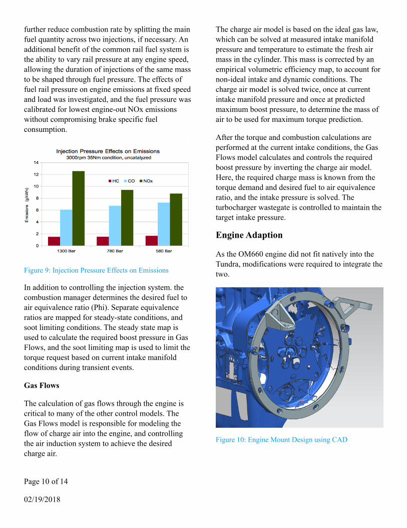
further reduce combustion rate by splitting the main fuel quantity across two injections, if necessary. An additional benefit of the common rail fuel system is the ability to vary rail pressure at any engine speed, allowing the duration of injections of the same mass to be shaped through fuel pressure. The effects of fuel rail pressure on engine emissions at fixed speed and load was investigated, and the fuel pressure was calibrated for lowest engine-out NOx emissions without compromising brake specific fuel consumption.
Figure 9: Injection Pressure Effects on Emissions
In addition to controlling the injection system. the combustion manager determines the desired fuel to air equivalence ratio (Phi). Separate equivalence ratios are mapped for steady-state conditions, and soot limiting conditions. The steady state map is used to calculate the required boost pressure in Gas Flows, and the soot limiting map is used to limit the torque request based on current intake manifold conditions during transient events.
Gas Flows
The calculation of gas flows through the engine is critical to many of the other control models. The Gas Flows model is responsible for modeling the flow of charge air into the engine, and controlling the air induction system to achieve the desired charge air.
The charge air model is based on the ideal gas law, which can be solved at measured intake manifold pressure and temperature to estimate the fresh air mass in the cylinder. This mass is corrected by an empirical volumetric efficiency map, to account for non-ideal intake and dynamic conditions. The charge air model is solved twice, once at current intake manifold pressure and once at predicted maximum boost pressure, to determine the mass of air to be used for maximum torque prediction.
After the torque and combustion calculations are performed at the current intake conditions, the Gas Flows model calculates and controls the required boost pressure by inverting the charge air model. Here, the required charge mass is known from the torque demand and desired fuel to air equivalence ratio, and the intake pressure is solved. The turbocharger wastegate is controlled to maintain the target intake pressure.
Engine Adaption
As the OM660 engine did not fit natively into the Tundra, modifications were required to integrate the two.
Figure 10: Engine Mount Design using CAD
Page ! of ! 10 14
02/19/2018

Engine Packaging and Mounting
To assist in packaging and mount design, the engine was scanned by an external company to produce a 3d surface CAD model of the engine geometry. A representative chassis CAD model was made to allow the engine model to be packaged virtually. Several engine mounts from the Tundra to the original 600 ACE engine were scanned and mounting points were used when designing the new mounts. Vibration isolators were used between the mount points and the new engine mounts, allowing the engine to move slightly and reducing vibrations transmitted to the chassis.
!
Figure 11: Engine Mount Stress Analysis
Cooling System
While the OM660 engine does not produce more power than the original Tundra 600 ACE, and thus the cooling capacity of the Tundra is adequate, the cooling system required careful design to ensure good cooling performance under all conditions. As the OM660 engine is mounted in the Smart Car in a reclined position, there is potential for air to be trapped in the cooling system in the new nearly vertical mounting position. A swirl pot was fabricated and added above the highest point in the engine, and the cap may be removed while the engine is run to purge air from the system.
!
Figure 12: Handlebar Support Displacement
Fuel Supply System
The fuel system of the original Tundra was designed to supply gasoline at pressure for a returnless port fuel injection system. As the Diesel engine has a mechanically driven high pressure pump, high supply pressures are not required. However, as the high pressure fuel system components are lubricated with fuel, a return line is required. For these reasons, the team decided to replace the entire fuel system of the Tundra.
As Diesel engines have a lower brake specific fuel consumption than their gasoline counterparts, and the utility focus of the Tundra leads to shorter trip distances at lower speeds and higher loads, a smaller fuel tank was chosen for weight savings. A Ski-Doo fuel tank from the MXZ-R ‘Race’ snowmobile was chosen, as it has identical mounting points to the original Tundra tank while reducing fuel capacity by 20L. This reduction corresponds to a 16kg mass savings. Additionally, this tank does not include an integrated gasoline fuel pump, allowing a more appropriate pump to be chosen. A low pressure inline lift pump with integrated filter module was chosen to supply fuel at low pressure to the engine pump.
As the common rail system operates at very high pressure, the temperature of the fuel is increased significantly due to compression. This results in a high return line fuel temperature. Fuel return temperatures were monitored on the engine
Page ! of ! 11 14
02/19/2018

dynamometer and verified to remain within the limits of standard rubber hose with SAE ratings for Diesel use.
Electrical System
As the new ECU replaces the original OM660 and Ski-Doo ECUs, a new wiring harness was built for it. To improve wiring fit and finish, an entirely new harness was designed and built. The electrical system features a Bussmann CAN controlled power distribution module, along with the previously discussed ECU and injector driver box. The Deutsch DTM connector system is used where possible, as it is easy to work with and provides a secure and water tight seal. Sensor wires are twisted and shielded where appropriate, to improve noise immunity. Heat shrink tubing is used to secure wires to connectors and further improve the water resistance of the harness.
Underhood Noise, Vibration, and Harshness
Many underhood components produce noise, and not all may be readily silenced. To attenuate noise produced underhood, a number of materials have been selected and applied. First, to reduce noise radiation through the sheet metal chassis, all chassis surfaces and body panels were coated in Dynamat Xtreme. Seams between body panels were also filled with Dynamat Xtreme, to reduce noise generated due to vibrations between panels. Where space permits, Dynamat Hoodliner was used to protect the sound dampening materials from high engine temperatures while improving noise attenuation itself. Near particularly hot components such as the exhaust system, foil mylar was used to protect the sound dampening materials from high temperatures.
Design Validation
Cost Effectiveness
The final MSRP estimated cost for the vehicle is $11,038. The Diesel engine is only $300 more
expensive than the outgoing 600 ACE. The price increase over the base price of $8,299 is mostly attributed to the aftertreatment equipment and the more advanced electronic control units required to run a common rail Diesel engine.
Emissions Test Procedure
Emissions and Fuel Consumption (brake specific) are evaluated using a Land and Sea water brake dynamometer along with a Horiba MEXA-7100 series gas analyzer and fuel flow meter. The same dynamometer configuration is used for engine mapping and calibration. As the Land and Sea water brake dynamometer was not able to absorb the full torque of the engine at low speeds and high loads, an AC dynamometer was used instead at low speed during some tests. As laboratory grade soot measurement equipment was not available, and the competition soot limit is significantly more stringent than can be visibly detected, a Stoneridge accumulator type soot measurement sensor usually used for on-board diagnostics was used to verify performance of the Diesel particulate filter. Emissions testing was completed using the Snwomobile 5-mode emissions cycle defined in 40 CFR part 1051 [2].
Emissions Results
Emissions tests were performed twice, with and without the aftertreatment system. The SCR system was not complete at the time testing was performed, and is not included in the results. The DOC was shown to have 83% HC and 99.3% CO conversion efficiency, reducing both to negligible levels. Soot was not detected following the DPF. The emissions results are compared to the previous Kettering entry, the EPA Tier 4 Compression Ignition standard for 19-35kw engines, and the NPS BAT standard for snowmobiles. Due to the huge difference between the NPS BAT requirements and the measured emissions, the graph is logarithmically scaled so that the HC and CO emissions are visible.
Page ! of ! 12 14
02/19/2018

Figure 13: Emissions Results (logarithmically scaled due to large variance)
Summary
Clean Diesel technology, in the form of a three cylinder engine featuring Common Rail Direct Injection, has been applied to a commercially available snowmobile. The goals of this effort included reducing exhaust and noise emissions to levels below the U.S National Parks Service (NPS) Best Available Technology (BAT) standard while maintaining or improving the utility of the snowmobile.
The Mercedes-Benz OM660 engine, used in the Smart Fortwo model 450, was chosen for its common rail injection system, all aluminum construction, and small size. The Common Rail fuel injection system allows flexible control of combustion and torque parameters under all operating conditions, and the custom control system exposes as much of this flexibility as possible to the calibrator.
Tailpipe emissions were reduced using an aftertreatment system consisting of a Diesel Oxidation Catalyst (DOC), Diesel Particulate Filter (DPF), and urea-dosed Selective Catalytic Reduction (SCR) are used to combat emissions. Noise emissions were reduced by addressing exhaust noise through a silencer, and mechanical
noise through careful application of sound dampening materials throughout the vehicle.
All goals were successfully achieved using cost effective technologies.
Page ! of ! 13 14
02/19/2018

Acknowledgements
Kettering University Clean Snowmobile Team would like to thank everyone who lent a hand in the completion of this snowmobile. Special thanks is given to Dr. Greg Davis, Dr. Craig Hoff, Clinton Lee, and the Mechanical Engineering Department faculty and staff for their support through the entire season.
The team would also like to thank its sponsors for their generous support of this project:
• Denso • Faurecia • GM Foundation • Fiat Chrysler Automobiles • Honeywell • Nord Ride Motorsports • Robert Bosch Corporation • Woodward Inc • Accurate Technologies • Stoneridge
References
1. Stumpp, G., Ricco, M. (1996). “Common Rail - An Attractive Fuel Injection System for Passenger Car DI Diesel Engines”, SAE Technical Paper no. 960780
2. Code of Federal Regulations, Air Pollution Controls, title 40, part 1051.
3. Blough, J.,“Snowmobile Design and Snowmobile Sound Basics”, May 8, 2009. http://www.snowmobile.org/docs/Snowmobile_Design_Snowmobile_Sound_Basics_May_2009.pdf
4. Takeuchi, Hirotaka, and Ikujiro Nonaka. "The new new product development game." Journal
of Product Innovation Management 3, no. 3 (1986): 205-06.
Contact Information
Dr. Gregory W. Davis, P. E. Faculty Advisor [email protected]
Page ! of ! 14 14
02/19/2018