Embed Size (px)
Citation preview
Design and detailing afstructuraI cancrete usingstrut -and -tie modeIs
':: ~c {
. J. SchIaich, Professor Dr.Ing.Universityaf Stuttgart,Germany
K. Schãfer, Professor Dr.Ing.Universityaf Stuttgart,Germany
\7i:>ZGt? BoVNA~S/!.~ ;=7~Reprinted from The Stxuctura1Engineerl\blume 69/No.6/19~~r'
~'""
., . . ~".'."-"'''''''~'';'';'-'''-o:&:..:'W..:.,...,...
~!... I
J)W\ I
fj,1
, If
! .
ti
iIJI..
r

J.
Paper
Paper: Sçblaich/Schãfer. i
Design and detailing af structural concreteusing strut-and-tie madelsJ.Schlaich, Professor Dr. Ing.University of Stuttgart. Germany
K. Schãfer, Professor Dr. Ing.University of Stuttgart. Germany
SynopsisSo-ct1lled 'details' are as important for a structure's behaviourand safety as the standard problems of design which arecovered in the Codes. A unified design concept which coversalso the details consistent/y for ali types of concrete structureis described in this paper. lt is based on strut-and-tie models,including the truss model for beoms as a special case. .
After the principies of the method and the modellingprocess are explained, simplified rules are proposed for
, dimensioningali the individual members of the model and.their nodes. Some exJ1mplesshow the application of themethod and demonstrate, also, its use for the improvement ofthe conceptual design of detait$.
IntrodUctiODCcnain pans of strUctures are designcd with almost cxaggcratcd ae<:uracywhileothcr pans are designcd using rules-of-thumb or judgment baseei onpastcxpcriCl1CC.Howevcr; all pans of a structurc are of similar importance.Aunified design c:oncept, which is c:onsistcnt for a11types of structurc andall thcir pans, must bc baseei on rcalistic physica1 modcls. Strut-and-tiemodc1s.a genera1isatioo of the wd1-known truss anafogy for beams. areproposedhc:reas thc appropriate approach for designing strUcturaI'c:oncrcte.whichincludes both reinforced and.prestresscd c:oncrete structures.
It was actuaI1yat the tum of the Iast century, when Riucr and Môrsch)introduccdthe truss anaIogy. 1bis mcthod was latcr refincd and expandcdby Lconhardt.. Rüsch'. Kupf~, and others. until Thiir1imann's Ziirichschoof. with Martil and Mudlcr'. acued its scientific basis for a rationalapplication in tracing the c:onccpt back to the theory of plasticity.
CoIIinsand Mitchd1IOfurthcr c:onsidcrcd the deformations of the truss
,. modcland dcrivcd a ratiQnaIdesignmethod fór shear and tomon.lo various applications, Bay. Franz, Leoohardt. Kupfcr and Thiirlimann
badsbownthat strut-aDd-tie modcIs c:ouIdbc uscfuIIy applied to deep bcamsmrcorbcIs. From that point, the prescnt authors and othcr mcmbers of
" theInstitute for Concrcte Structures at 1he University of Stuttgart began!bar cffons systematically to expand such modcIs to cntire structures andali struc:turesll.l2.
Thc mcthod had bcen explaincd aIreacly in some detail in the Amcrican
PC! Joumall. The interated readcr is refcrred to this paper as a basis of
lhe prc$CIIt C:OÍltributiOIL Here, the dcvdopmcnt of st1Ut-and-tie modcls
lIId thc dimCDSioDing of thc:ir SUUts. ties and nodes will bc rcpeatcd onlybricfIy. Coucanmg lhe design of nodes. some material which goes bcyondrã. I is addcd.
1'beD. lhe method is applicd to a fcw ncw cxamples. including some
comparison with test results. Some of the cxamples given show that the
1InIt-lJld.tic method is useful not only in dimensioDing given mcmbers bur
< 11IoiDdcvdopiDg an adcqUate c:onceptual design for a critica1 detail.
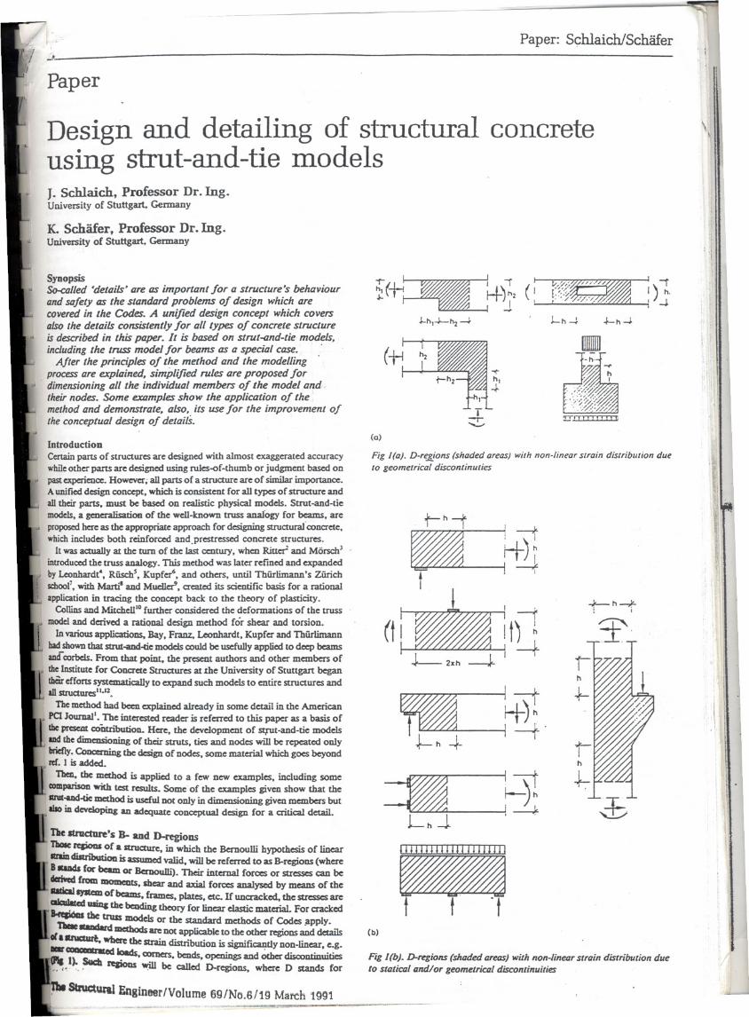
Tbe Itract1lre's B- aud D-regioDSTIIOIcrqioas of a Structurc, in which the Bcmoulli hypothesis of linear
, ltrIÍDdisIributioD is assumcd valid, wiII be referrcd to as B-regions (whcreB8IDds for bc:8m or Bcrnoulh). Thc:ir internal forces or stressCScan bc
::: from lIIOIDents,sbear and axiaI forces anaIyscd by means of lhelJItem ofbcams. fnmes, plates. etc.. Ir uucrackccl, the stressCSare
CIIcaIItedIIIÜI&the bc:ading theory for linear dastic material. For cr3ckcd
. '= &betruss modcIsor lhe standard methods of Codes ;t.pply.oC 88Ddard mcdaods are DO(applicable to lhe other regions and dc:taiIs
llIIUaart. __ the Sttaindistributionis significandynon-linear.e.g... - 'C.-odlo8ds.comers.bends - and ~ disc:oDtinuitiestPIaI). Sucb '. .~"__ .~' '. . l'eIiODs ~ bc callcd D-rcg!ons. whcrc D stands for
Stnactuml Enifneer/Volume 69/No.6/19 March 1991
iC+~ ~)} (~J..",-J.-hz~ . 1-"-4
(a)
\\
I
1)1.'-J.
~,,-J.
Fig /(0). D-re.gjons (shoded oreas) with non-/ineor slroin distribl/lion dueto geometrico! disconl;nut;es
~t-"-t ; -tH-),
ft
--iI1) ~
---J...: t
~L"J.
1\11--)"j --=-..J.<.
(b)
,
1<-"-+. ,
p.r-"~
J:;
Ftg l(b). D-regions (shoded aretlS) wilh non-linMr $lroin distribul;on due
lo $lalim! and/or geomelrim! disconlinuilies
J.
Paper
Paper: Scblaich/Schãfer . i
Design and detailing af structural concreteusing strut-and-tie madelsJ.Sch1aich, Professor Dr. Ing.University of StuttgaIt. Gennany
K. Schãfer, Professor Dr. Ing.University of Stuttgart. Gennany
SynopsisSo-ci1lled 'details' ore as important for a structure's behaviourand Sllfety as the stantkzrd problems of design which arecovered in the Codes. A uniJied design concept which coversalso the details consistent/y for ali types of concrete structureis described in this paper. lt is based on strut-and-tie models,including the truss model for beams as a special case. .
After the principies of the method and the modellingprocess are explailled. simplified. rules are proposed for
. dimensioning ali the individual members of the model and.their nodes. Some examples show the application of themethod and demonstrate. also. its use for the improvement ofthe conceptual design of detailS.
lntrodUctiODCenain pans of strUctures are dcsigned with almost cxaggcratcd accuracywhileothcr partS are dcsigncd using rules-of-thumb or judgmcnt baseei onpastcxperience. However; aUpartS of a str1JCturCare of similar importance.Aunified dcsign concept, which is consistcnt for ali typcs of structurc andall thcir pans, must be baseei on rca1istic physica1 modc1s. Strut-and-tiemoclels,a geoeralisatioo of the wel1-mown truss anafogy for beams, areproposedhere as me appropriatc approacb for dcsigning StrUcturaI'concrcte.wbichincludes both reinforced and.prcstrcssed concrete structures.
It was actuaUy at the turD of the Iast ceDtury, whcn Riuer2 and Mõrsch)introduccdthe truss anaIogy. This method was latcr refincd and expandcdby Leonhardt', Rüsc:h', Kupf~, and others, until ThÜf1imann'S Zürichscboof, with Martil and Mudlc:r', creatcd its scicntific basis for a rationalapplication in tracing the concept back to the theory of plasticity.
Co1linsand Mitchel1lOfurthcr considcrcd the deformations of the truss
I" mocldand derivcd a ratiQnaI dcsign method fór shear and torsion.lo various applic:ations, Bay, Franz, Leonhardt, Kupfcr and ThÜfIimann
badshownthat strut-aud-tie modds couId be uscfuIIy applied to deep beamsamrcorbels. From that point. the p~ authors and othcr members of
" IbeInstitute for Concrete Structurcs at 1he University of Stuttgart began. tbâr effons S)'Stematically to expand such modc1s to cntire strUctures and
alistruc:turesll.l2.
Thc method had been explaincd a.lready in some detail iR the AmericanPClJoumal'. The intc:restcd readcr is referrcd to this paper as a basis oflheJII'CSCIItcoÍ1tribution. Here, the devdopmcnt of squt-and-tie mode1saad thc dimensioning of their struts, ties and nodes will be repeatcd oolybriefly.Couceruing me dcsign or nodes, some material which gocs bcyondrã. I is addccL
1ben. me method is applicd to a fcw DCWcxamples, including somecomparisonwith test results. Some' of the cxamples givcn show that theIIM-ud-tie method is useful not ooly iRdimensioning givcn members but11IoiR devdopüag an adeqUate coDceptual dcsign for a critica1 detail.
Tbe 1tnIc:tare's li- aad D-regioDSThaIe rqioas oCa struc:ture, iR which the Bemoulli hypothcsis of linearlIrIiDdistributioa is assumcd valid, wiIl be referrcd to as B-regions (whereBlCIDdaCorbam or Bemoulh). Their iDtemaI Corces or strcsscs can bederhed from lDOIDeDts.sbcar and axiaI Corces anaIyscd by means of thelI8tIcI1~ oCbQms. &ames. platcs, etc. Ir unc:racked, the strcsscs areCIIcüIred UIIIICthe beuding theory Cor linear eIastic: material. For cracIccd~ lhe truss modc1sor the standard methoclsor Codes ;apply.oC lt8IIdard metbods are DO(applicable to the other regions and dc:taiIs
al&nlClurt. wb= the strain distn"bution is significantly non-linear, e.g.
_~.ed ~ ~ bends,openingsanclOtherdiscontinuitics1<_.". '.' ftIioDs ~ be ca1IcdD-regions, where D stands for
~l Eniineer/Volume 69/No.G/19 March 1991
i~~ ~)} (~J-h,-J.-hz~ . J- h~
(Q)
\\
I
1)1.'-J.
~h-4
Fig I(a). D-re.sjons (shaded areas) with non-linear slrain distriblltion dueto geometrical discontinuties
~t-h-t i ---t~)I
-ft
-iI1) ~
---J.."~
~Lh.J
1\11--)hj --=-..J.r.
(b)
+-h-+. i
l'
h
Fig l(b). D-regions (shaded areos) wiJh non-linetlr srrain distribulion duelo sratica/ and/or geomelrica/ disconlinuilies

New strut-and-tie mode1s can be systematica1ly deve10ped by uaáng the
flow of forces through the structure, using the 'Ioad path' method.The stress diagrams of ali the forces applied to the D-region boundaIies
are subdivided in such a way that the individual strcss rcsuItaDts on oppositesides of the D-region corrcspond in magnitude and can be connec:ted bystream1ined 'Ioad paths' which do not cross each other (F'1g2(b». Aftersketching the load paths smoothly c:urvedand replacing them by polygons.further struts and ties must be added for transVerse equ,ilibrium (F'1g2(G».Obviously, in some cases the stress diagrams or the loadS are not completelyba1anccd with the 10ad paths dcscribed; then the 10ad path for me rcnainingforces enters me structure and leavcs it after a U-tum 011me same side(Fig 3).
I ' I DeveIopinga mode1of a D-regiOI1ismuchsimpliíJedütbe cIasticstresSeS'
J-oS_{ ~ and principalSUCSSdiRctions are availablefrom an dastic FEM aDalysis.I ,- \ ': The directionof struts can then be taken ia aa:ordance with the mean andI \ "\~.... main direction of principal comprcssivestrcsscs, or the more imponant
T T~ T 0\ struts and tiescan bc located at the centreof gravityof the strcssdiagram~
t - - of typical sections (F'1g4). '
Ao ' Bt tA Bt tA Bt Wben mode1ling, ~e aqIcs bctwecD struts and tics. ia particuJar thase, ) o . with re1ative1yhigh forces, should be choscD~a (b) (c) ia order .~.avoid incompatibility problems.,.,~ '*"f1
F"tg2. 'IM,Joad palh merhod: (a) lhe stl1lcture and its loads; (b) lhe load ;". .,- The resulting mode1s are q~which means that thepalhs through lhe stl1lcture; (e) lhe co"esponding strul-cnd-tie rnodel geomCUyof such a model is strictIy related to a particWãr 10adconfJ.gUIation
Paper: SchlaichlSchãfer
.discontinuity, disturbance or detail. The interna1 fiow of forces ia D-regionscan be reasonably we1ldcscribed by strut-and-tie mode1s.
Not much accuracy is ncc:cssary in detcrmining the dividing sectionsbetwecn B- and D-regions. Thcse sections can be assumed to lieapproximate1y in a distance h from the gcometrical discontinuity or theconcentrated load, where h is equa1 to the depth of the adjacent B-region(F1g I). This assumption is justified by Saint-Venant's principiei.
Principies or strut-aod.6e model designIn a strut-and-tie mode1 the struts represcnt concrete stress fields wit~prevai1ing comprcssion in the direction of the strut. Accordingly, the tiesDOrma11yreprescnt ooe or severallayers of tensile reinfor=nent. However,mode1ties can occasiona1ly aIso stand for conaete tensile stress fie1ds. Thisis evident from models of practica1ly approved detai1s. the structuraI safetyof which can bc explained oo1yif coocrete ties are assumed in places whereDOreinforo:ment is provided. Typica1 cx.amples are slabs without stirrupsor bar ancbo~ without spiral or uansverse reinforo:ment.
If a suitabt'e~m~e1 of a D-region is knOWD,the forces of the struts andties will bc calculated, thcrcby satisfying equilibrium betwccn applied loadsand inner forces. The struts, ties and their nodes will bc dimensioned orchccked to carry the inner forces, as described later.
This method implies that the struaure is designed acx:ording to tbe lowerbound thcorem of the thcory of plasticity. However, since structuralmateriais. in particuJar concrete, permit only limited plastic:deformatiODS,the internal structural system (the strut-and-tie model) has to be'chosenin a way that the deformatioo capacity is oot exceeded at any poinr:; beforethe assumed state of stress is reached in the rest of the structure.
In highly stressed regions, this ductility rcquirement is fu1filledby adaptingthe struts and ties of the mode1 to the direaioo and size of the internalforces as they would appear from the theory of e1asticity.
lo norma1ly or lightly stressed regions the direaion of the struts and ties )..~,.in the mode1 may deviate considerably from the e1astic: pattem iViDiõút' "exceeding the structure's duc:tility. Thc ties, and hence the reinfor=nent,may be arrangcd according to praaica1 consideraàons. The structure adaptsitse1f to the assumed interÍW strUctwal system.
This method of orientating the strut-and-tie mode1 aIong the fora: pathsindicated by the thcory of e1asticity obviously neglects some uItimate loadcapacity which could be utilised by apure applicatioo of the thcory ofplasticity. 00 the other band, it has the major advantage that the samemode1'CaI1bc used for both the uItimate load and the serviceability chcck.Ir, for some rea5On, the purpose of the analysis is 10fmd the actual uItimateload, the model can easily bc adapted to this stage of loading by shiftingits struts and ties in order to increase the resistance of the strueture. In
~ case, however, the rotation capacity of the mode1 has to ~nsidered.
~t-and-tie mode1ling obviously provides the struaural aDalyst withsomei!~om of choice which can be used 10 aim-eíther at the safest or O"at the Cheapest or at an otherwise optimised solution. Mode1ling thereforercquires some dcsign experieooe as does the c:boiceof a represcntative overallstatical system or of a rcàsonable fiDite dement neL\. "\~t"
The moddling process aIso covers much of what is DOrma11ycaIIeddetai1ing and thcrcfore requircs considerable knowledge about practicablereinforccment layout; 00 the other band, it is just in this fie1dwhere strut-and-tie models rcplace experience anã gucssworlc:by a more systematic andunderstandable designo
ModeIIiDg of iDclmdual D-regionsBeforemoddling of a D-regionbegins,ali the forcesand reactionsacting00 the D-regiODmust be evalUated(Fig 2(a». The forces or suesses iasections bounded by B-regionsare taken from B-regiODdesigne
q~
....
r \
(o)
q~
Fig 3. The load palh melhod. including a 'U-turn ': (a) lhe slruelureand its loads: (b) lhe load palhs IhTOlIg" lhe SII1l~lure; (e) lheeorresponding slrul-cnd-lie model
1.0 1.0 1+0 1.0
I.' .1. I;"" I. I;""'1. "I
~ J J ~ J ! ~ ~ ~ ~ ~ ~ ~ ~ ~ ! }-q
J tFo~L
ítl u_~-Jo~ IC
..IFig 4. E/aslie Slress Irajeclories, Jislribulion 01 elaslie stre:sses, andcorrespandingsll1ll-cnd-liemodel
The Structural EngineeÍ'/Vo)ume 69/No,6/19 MatÇb 1991
r r
fi1]d-
path ._c
dI1Jq
F 81 82
(bJ 81 :: 82 (cJ

.....
Paper: SchlaichlSchãfer
+ \=
FI ;;!:O'3F
Fig 5. The comb~nalion of two models for the dapped beam is better than the individual models
F:FI+FZ
i U 111111I1i 1111111 U 11p U Ii 1111111111111111111p
1I I
1I II I
1
J I--1
lid:':: I I
~
d:1
z I I I I Z
1I I I I
JI I I"I
I II II I
} \I \
I \I \
I \I \
whcre
F., is the force in strut or tie iI; is the length of membcr ie... is the mean strain of membcr i
The contribution of the concrete strulS can most/y be omitted iDthe abovecriterion.
: ,If
(a) Good (b) Bad
Dimensioning the strulS. ties and nodesReinjorced and unreinforced ties'Normally tie forces are carried by reinforcement. 115cross-scaiOD foUowsfrom the tie force in the ultimate limit state and the design yidd strengthof the sted.
For crack distribution the reinforcement shall be distributed ovcr thetensile zone. Crack widths can be ana1ysed if the reinforced tie is considcred
as a prismatic reinforced bar with an effective concrete arca.The tensile Strength of concrete should be ulilised for equilibrium forces
only if no progressive failure must be expected and ir local failure zonesare assumed. Thereby restraint forces and microcracks have to be takeninto account even in 'uncracked' concrete. Funhcr. some positive experiencewith similar details and loading should be availablc.
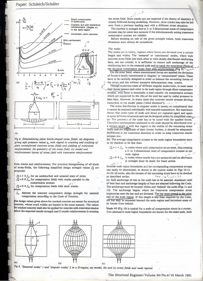
and canoot be used for othcr loads withoUI modificatioD. Thcrefore. the Concrete strurs or compression stress fieldsgovc:ming load combinatioDS have to be investigated. This disadvantage To covcr ali cases of compression stress lidds. three typical configurationsis DOta pccu1iarity 01 the strUt-and-âe method but is inhcrent to the nOD- are suffiaent:linear matcdaI properties of cradced conaete.. (a) The fan-shaped Stress fidd (Fig 7(a» is an idealisation of a stress fidd
Accordingly, superposition oftwo models is possible only iCthe combined with D~ligible curvaturc. It does not devclop transverse stresses.modd satisfies the requirements ODreasonable angles bcrween struts and (b) The bottle-shaped stress field (Fig 7(b». wilh its bulging stressties. By c:ombining two súople models it is sometimes possible to devdop trajectories. devdops considcrable transverse stresses: compression in the
muchbeUcrbut rachercomplicatcdmodels(F1gS). Insteadof invcstigating \ !..,'bottle Dcck and tensioD funher away. The transverse tension can causesuch a hyperstatic modd with tCpreseDt3tÍve stiffnesses of the struts and \,( longitudinal craclcs and initiate an carly failure. It is therefore oecessaryties. it is oonaally more adequate to immediatdy aUot "tliêloads to the two - to reioforce the stress fidd in the transvcrse direction or to considcr thesimple models with an eye ODthe cxpec:ted stiffoess ratio of the individual transvcrse tensiOD when detcrmioing the failurc load of the strut. Themodels. .. :' " transvcrse tension can be detcrtnined from a strut-and-tie modd of the stress
Doubts c:ould arise as to whethcr tlte correct mode1 has been chosen out fidd. Diagrams simplify its dimensioning (Fig 8).of sevcral possible ooes (F1g6).10 sdecting the modd. it is hdpful to rea1ise (c) The prismatic or paralld stress fidd (F1g7(c» is a frequent special casethat loads try to use the path with the lcast forces and deformatioDS. Since of the preceding two stress fidds.reinfon:cment ties are much more deformable than c:oncrete struts. the The fan-shaped and the bott/e-shaped stress fields are frequently foundmodd with the leas(and shoIlest ties is the best. This simple criterioo for -in D-regiODSwhcre CODcentratedloads are introduced into a structurc andoptimising a modd may be formulated as foUows: sprcad out. The prismatic stress fidd is typical for B-regions.
J;Flre -=minimum The strength of the çoDcrete iDcompressioo stress ije1ds d~ds to aI - considcrable extent 00 the multiaxial state of stress and 00 disturbances
Fig 6. The good model (a) Iuzsshorter ties Ihan the bad model (b)
b
1ti ftt tff+'O'~f~I-a~
UUIUU
I
I
f tt ft ff H"O':i ~
f-a--4
(c)
Fig 7. The basic r.ompression fieltis: (a) the 'lan'; (b) lhe "bollle'; (e) lhe "prism'
(a)
\\\ tftJtI-O':gf~
Lt (b)
Th~ ~tH h._l ~ :_" I""I " ~n/ll.'" 1::/11'1\I.._J. 11'101
, ", ,," /'" "D/ "(;$"7 '"'1' '"
~/ r:;'b",'" - Uncrac:kCd.ploinconcrdf:// ~~" L~~
",/ / . C~~;!'tWith aminf:mart. '" ,,(S././ _ _
,- ';>H-'- Without l:-
1
~ii-: \
jl
~~~ -;
~b t);\,~". ..:.
(~;; j-: Fi. ·2 ~ 1''' X /z-A- f: =- E
F=Pa.a.t t- y
Paper: SchlaichlSchãfer
'200
Pa
fca
w=~t. fCd
~ 5 6 7
..,)'
j1
c\; : \,,'I, \I \ I
( \I tT I
.~._lf--I + a---lb I
Biaxil COIIIprf:ssionin bottlf: nccIcCro:kCd. but with tI'cInsWfsf:rcinfOtCf:momt (df:gmc w)in thf: bdly rcgion
'f'a-f
/J=b/a
8 9
" ,0,21
L--1'31+a-!b
~ (e)
:Fig 8. Dimensioning pÚlne botlle-shaped stress fieltis: (a) diagramsgiving Sllle pressure values Pa with regard to eraeking and erushing 01plain unreinlorced eoncrete stress fieltis and yielding 01 transverse.reinloreement; (b) geometry 01 the stress field; (e) model and'reinlorcement layout 01 stress field with transverse reinforcement
from cracks and reinforcement. For practical dimq1Sioningof ali kindsof strcss-fields, the foBowingsimplified design strcngth valuesf:J are~roposed: .
~ ~ =l-O lod for an undisturbed and uniaxial state of strcssl ~=0'8fod for comprcssion fieldswith aaclcs parallel to the; compressi9nstresses ,p,'L':.; ~=0'6fod for compression fields with skew aaclcs;"-here(104 denotes the conaete compressive design strcngth for uniaxial
comprcssion aa:ordiDg to the Code of Practicc.
if'he dcsign values givcn above for aaclced conaete are meant for struc:tural~Dc:rete, whose crack widths are limited in the usual manner. The valuesror c:racb:d c:oocretcsbaBaIso be applied for conc:retcwith tr.msYCrsetalsionlIelow the c:xpected tcusile strcngth and ü tensile reinforc:cment is crossing~.
(Q) - - (b) - - (e)
~tg9. 'Smeared nodes' I and 'singularnodes' 2 ;n o D-reg;on;(o) model, (b) and (e) stressfiel tis ond nOOeregio~
2
I
. ...!.........'
~
the strcss field. Skew aaeks are nOIexpected if the theory of elastidty isclosely followed during modelling. However, skew aac:ks mayalso be leftover from a previoos loading case with a different strcss situation.
The inaease in strcngth due to 2- or 3-dimcnsional states of compressivestresses may be taken into ac:count if the simultaneous1y acting transversecomprcssivc stresses are reliable.
Before deciding on one of the given strength values, both transversedirections musl always be considered.
\\
The nades
The nodes are in rcalily. regions wherc forccs are deviated over a ecnainlength and widlhs. The 'smeared' or 'continuous' nodes, where wide
concrete stress fields join eac:hother or with closely distributed reinfordngbars, are not critical; it is sufficient to ensure safe anc:horage of the
reinforc:ing bars in the smeared node and to catc:h the outermost..fibres of ., :the deviated eomprcssive stress field with reinforcement (Fig 9): ,;.1'.:.
'On the other hand, where conccntrated forces are applied the deviationof forces is loc:allyconc:cntrated in 'singular' or 'conc:cntrated' nodes. Tbesehave to be carefully designed in order to balancc the oncoming forces of
r, the struts and ties without exc:cssivedeformations resp. c:rac:ks.l. T!ioiÍglI' numerous cases of differenl singular nodes exist, in mOStcases~.' their forces balance eac:hOlha in the node region through direa c:ompressive
strCSSés-:-Ãfsõõond is essentially a load transfer via compressive stresseswhic:h are supponed by the ribs_of the stcel bar and by radial prcssure inbenl bars. However. in many cases also conerete tcnsile stresses developtransverse 10 lhe model plane ('third direction').-. ,', "
The stress disrribution in singular nodes is mostly so complicated thatit cannol be analysed individual1y with bearable expcnditure. But experienccshows that some types of node and detail are repeated again and again
in quite different structures and can be designed sa~ely by simp~fied rul~:~ , \(a) The geomctry of the node has to be tuned "w1th the applted forces.
Therefore reinforcement anchored in the node should be distributed over J' ba cenain height l!..with due regard 10 the widths of the oncoming strcss . ;:
IfieK!s ane. the magmtude of their forces; funher, it should be adequately \disctibuted in the transverse direc:tion in order to keep traDSVersetcnsilestrcsses low.
(b) The average compicssive stresses in the node regioo boundaries have
to be checked to be less than . .-:) .
~.1
1.4=1'11:. in nodes where only compression struts meet, thos creating
a 2- or 3-dimenSionalstate of compressivestressesin the .node region ~.! ",' '=in nodes where tensile bars are anc:hored and an allo\vanc:e
in strength most be made for bond actionfc4=0'8fc.
_c/'"~'. .JSuitable node region boundaries aI!d the corresponding compression str:ssesc:an easily be determined, as shown in the typic:al nodes in Figs 10-13.As for ali nodes. a1sothe stresses of the oncoming struts have to be c:hec:kedas described earlier. L>,.>. f; ,: .~,~)(c) Safe anc:horage of ties in the node has to be assurcd: minimum radiiof bent bars and anc:horage lengths of bars are selec:tedfoBowing lhe Code.The anc:horage must be loc:ated within and 'behincP the node (FJgS 11 and13). The anchorage begins where the traDSVerse compression stresstrajectories mcet lhe bar and are deviated. The bar must extcnd to the otherend of the node region. If this length is Icss than required by the Code,the bar may be extended bcyond the. node region and introdllCC some ofits forces from behind.
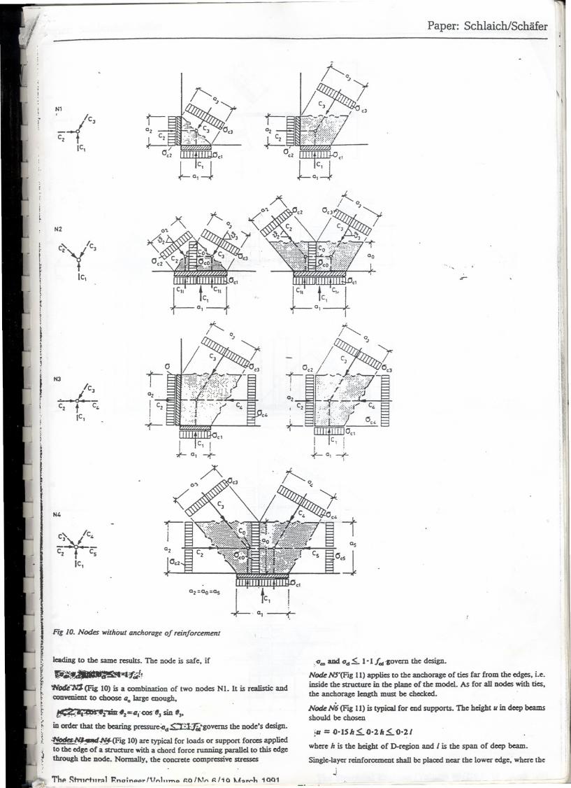
NOOe Nl {Fig 10) is typic:al for a node of compression strDts in a comer.. Two alternative node region boundaries are shown for the samc node, both
!I,
11
The Structural Engineer/Volume 69/No.6/19 March 1991
o1 2 3
(a) ,..
:"
rI!
r-Ozc
.J.20 I""I'" 11<'<
c2Lo~j
N1._-(
IC3
C2
IC,cl
J-~~J
N'
c} Iclo-~Cz f Cs
IC,
O2
OczCz
Qz=ao=as
Fig 10. Nodes wilhout andwrage of rdnforcemem
leadiDg to lhe salDe RSUIts. 1bc node is safe, Ü
P~JJ ~._"'4t'31Wotll""NJ(F'ag lO) is a combination of two nodcs NI. It is rcaJisâc andCODYeDiaItto choosC (loIarge CDough.
~..~;mr.2I1:Q"<OS-"J sin "p
in order that the bearingPrcssure~d~'govcms thc node's design.
~tltslq~~(F'ag lO)are typic:alfor loads or support forcesappliedto theedge of a struc:turewitha choreiforce rwming paraIlel to this edgethrough the DOde.Normally, the concrete comprcssivcstRS5CS
Th.. ~tn,t't1tT:>1 ~nCJ;n..",..I"nl o ~o/"'n ~/'o u h 1001
Paper: Schlaich/Schãfer
\~
'., .. I..1í-
t-}~'~o ~
- / ~J JOC2
fti/ -- .. . °C3:.:' ":':':""'~
~J~i~'~~~~ :;;:::;}f;:'.~}::?:;'0C~~
IIIIIDIIIJ OCI
I Ic, I
~01-+
'f'-.-. ~
I'Ii
I!
~
:.~...and 0d.s.. I- I fel'JOvem the designo
Node NS'(FJg li) appIics to the anchorage of tics far from thc edges, i.e.iDside thc structurc in the plane of the model. As for aU nodcs with tics,thc anchorage lcngth must be chec:ked.
Node N6 (FJg 1I) is typic:al for cnd supports. 1be hc:ight li in deep beamsshould be ch05CD
i" = 0-1Sh.s..O'2h.s..O-~1
wherc h is the height of D-regionand I is the span of deep beam.
Single-laycrreinfon:cmcntshaUbe p1ac:cdDcarthe lowcredgc, whcrc thcj
N2
IC,
c}y 3
,.
t. 'tc,I
r
fI,
,
í
I
N3
IC3I.. -... C
Cz t lo =IC,
-.r- c,
10,c+

ipaper: Schlaich/Schãfer
r-r
l.
rHS,i "C2E /IrT\C,
!I.l
L6rl" tc~ I 2
rr. rT C't .c,~,Ii1
IC3I
c;-rTIc,
.
f~T, t Tz
Ie,~~~
,
\
A
X></ /
H HHH \ \
~~~O\
11> -f
i
~. '1/',"iT3 , I~ ~Ib~~e.
I~
l~!.t..~}
f-ig 11. Nodes wi/h andronzge 01 rei1!/on:ement~f
T
<C"J>
I~
f~,~~
. I ~2~ -.1-H'~~ -T ~,.W~.,..
I~
/~{. " -/ -T~u-o
l~ lO" .. I ~O"0,=1 ~IlI 1>.
T u
=-J-
.t1:F~II>~
T2 T2
. T, 11..T, T3
J-II>.ot
u=a2
U,=Uz=Co ~c,
B~~
The Structural Engineer/Volume 69/No.6/19 March 1991

MO
Tt /cLT
tII,
I
t Fig J2. Node wilh devialion of reinforcemenl
lIS~C1\
ffiOc"JaJ
fII4"I1I1~_., ,
J I~\ I~-4 .
I~I:~:'~
Ts
~'1--+1
I IJ I
~\ I
. lt .
L~
Paper: Schlaich/Schãf.
Frg J3. Trt!Jltmenl of IOCIIIpff!SSUTe in Iypiazl nodes N2 and N6. appliazble also 10 olher nodes
deviation forces are largcst. Chccks include
~-Võ.l/~~.'.
~Jg 11)is typicalin the tcDSionchord of beamsor d~ beams.1'hin. wd1~õut.cd bars sball be choscnas rcinfon:emcntfor de li andthcy shaI1cmbrac:cde Ta. CoDcretcstresscsPc SOO.Sf wiIl rarely bedccisive.
~ (FJg 11) iS a mixture of the nodes Nl and N6, and thcrcforemaximúm compressiODstrcsscs bctwccn thosc of both node types areproposed.:
~.;.::>J A. jp .."" ." .~.,..
Bcsides-; the 'iúIcs' for typicai node N6 apply.
MlR-A9(FJg 11) is composed of two nodes N8; chccks are aa:ordingly.1bis Dode is typical1y ovcr lhe support of coDtinuous beams md normaUyaIso COYa'edby lhe Codc rulcs (c:heck the beam's c:roswcction for Mo N8IId V, bcariDg pressure, anchoragc of chorei reiDforccmcut).
Wõi7~ 12)is c:heckcdvia thc admissible~us of thé bem bar.In DOdcswith local prasure (a. < I, f'Jg 13), thc ttansvcrse tc:DSionin thethird diRctiOD must be COYa'edby traDSVcrscrcinfora:mcnt dcsigDcd for
. 1 l-a.~
I
D T-4X'x C.
~ J TbeStnlctural Engineer/Volume 69/No.8/19 March 1991-..."'\
~
Local pressures.oCIImay be tolcratcd up to
! C I .'Octt=-l.s..-~s.. 3.3f.
Y. -a.. .
General rufe
5ince singular nodes are bottlenccks of the stresscs. it c3n be assumcd thatan CDtire D-region is safe. ü the pressure undcr lhe most heavily loadcdbeariDg plate or anchor platc is 1css thaD 0,6 f.. and ü ali siguificantteDsile forces are resistcd by rcinfon:emcnt and furthcr ü sufficientdcvelopmcnt lcngths are providcd for the reiDfora:meDt.
Only if this rule does DO(lead to a primctory result. more SOJ)himc:a1cdanalysis, as dcscribcd carIicr. is rcquircd.
AppliC2tiODSODly a fcw applications of the sttut-and-tie method can be shown hcre;many more can be found in refs. 1 and 12. .
<~ .
Corbcls are D-regions for wbich SUUt:and-ticmodcIs areapplicd successfuJlyfor a loDgtime. For a chec:kof themcthod and the dt:sigDrules sM:n above,a tcst spccimen wiIl be analyscd and thC results comparcd With the testrcsu1ts. In ordcr to include also thc poCCDCjalCODcretcfailurc in lhe chcclcs.ODeof thosc rarc test speciMeo~u is scIcctcd for wbich yidding of lhe mainde is Dot the obvious faDure critcriO"I1.
--

~.
\ f,'Paper: Sch1aich/Schãfer~~
a-a
r.Tto
r+'"
f~
~,
r t
51irrup11Iti.
6 Loops11I25
laIZlptcrtlZ
03001200130
5implifi<Zdmodd X R<Z1In<Zd rnod<Zl
F
I
B;~t=0'30
..-"U. CorlJeJ:(a) lestetl sP«imen no.213; (b) crack pattem 'at13S01cN(Ile/Ulaüure); (e) simplij2J and reflned strut-and-tieId 01 intemallorces at lailure Ioad F. = 1'42SMN
"
.. ...~.J :,.I
Iest $pCCÍmca n:presc:utiDg two symmctricaJ.eorbels was tested upside(Fag l4(a». Thc crac:k pattcm depicts1iiüte we1l the intemal' flow
. ~Ora::s (F"Jg14(b», condeased in tbe simp\ified model (F"Jg l4(c) lcCt side).
jIs mocIeI c:an easily be derived by tbe load. path method. However, the. model geometJy is known onJy aftcr the nodes are dimensioned.
\ li
T=C. = F.ltan 8
Taking a strut angle 8= 33° from a fim sketch ofthe model. the foUowinginternal forces are derived for the recorded failure load Fu= 1'425 MN:
F./sin 8
= 2'19 MN
= 2'62 MNC:=
Tie T:
0.= TIA.= 359N/mrri2<f., = 452N/mm:Nade I:
0.1= ~_ 1'425a. x a, - 0'30X 0'20 =23'8N/mm2
II
< ~ xh' = 0'30 x 0'8 x 26'3 = 31'6N/mm1(localpressure)a, 0.20
Transverse tension from local pressure is covered by loops and stirrups.Anchorageand distributionof reinforc:cmenlia the node regionis adequate.
C. 2'62o.. = -=-- = = .19'8N/mm1.. a: x I 0'44 x 0,30
.\
<0'81.: = 21'ON/mm1
Nade 2. The concrete stresses in this i>ure compression node (similar totypical node N2) cannol be critical.
o, < I' I 1.:.
if the stresses in lhe adjacent stress fields are satisfactory.
II
'\,
SlrUIC:. The diagram for bottle-shapedstress fields (Fig 8) willbe used.
Reinforcementralio: vertical c.Jy= 0'08. horizontal "'. = 0'13.For", = 0,08 the diagram predicts a ~inim.!1m.capacity
P. =0.75 fc = 19'7N/mm1 :l' ',:'~
which almost exactly coincides wilh lhe pressure ~= 19'8N/mm1determineclfornodeI in lheultimatecondition.Ind~ failedin the tCSIafler yielding of lhe vertical reinforcement. The same width Q2is necessary in the other botde neck of the stress field where it joins node2. This det~rmines lhe geometry or node 2 and final1y that of the simplemode!.
However. it must be pointed out lhat the strut angle 8 = 33° < 45°indicates a rather poor orientation or lhe simple model at lhe elasticbehaviour. A refinecl mooel is given in Fig l4(c), right side. This modelimmo:diately explains lhe forces in the yielding vertical stirrups (tie T~ andleads to rcduced stresses and anchor forces in node I. which Iherefore c:annotbe critica!. The geomCtry and the checlcs for oode 2 are unchanged ir the
resultant C. or struts_ c; an~~is C!!nsidered. Stresses in the diagooaistrutsare '";ôt higher tfu.1i in e simple model.
i
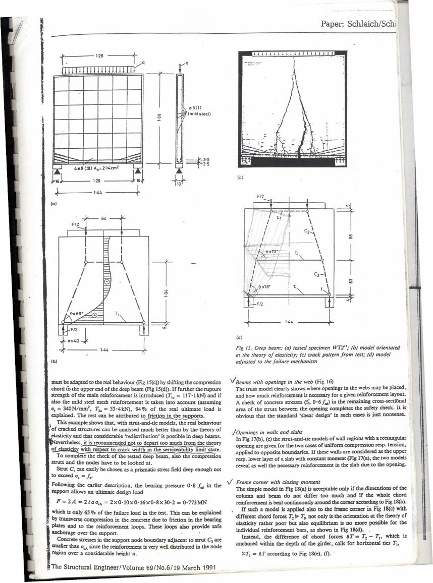
Deep beamThe deep beam tested by Leonl1ardt & Walther.c sbaU be evaluated usingthe strut-and-tie method. Dimeosions and reinforcement layout are givenin Fig 15(a).
f. = 30'2 N/mm1 cooc:reteprism strength11'/ = 428 N/mm1 yield strength of maio reioforcementf", = 547 N/mm2 rupture sttength of main reioforcement
The test specimen failed at a totalload F. = 119SkN aftcr rupture of lheprincipal reinforcement. .!.
For a fi~.Pm:.~mati_oo the model from FJg4 wi11be used (Fig lS(b».neglectiDi--tiie-d~ii" of bars near the support and the meshreinforcemeot. The lever arm of the chord is assumed to be DOImuch largerthan expected from the theory of elasticity:
%= 0'72 / = l'04m
When the' teosioo chord begin.s to yield,
T1y = A. xJ., = 2'I4x42-S = 9I-6kN,
the corresponding load amounts to
F. = 2x T.yX%= 2x91.6x 1.04 = 476 '.J e 0-40. ......
This is already more than the ~ desip would predic:t,but onJy40'10of the measurcd failure load. .
However, for an cxplanation of lhe recorded ultimate load. lhe model-...
. .J
1ZSlirrups_88x J
101515 7.Sem ...I .. .. . .., .. I' . II"
I , ".. .. ....... ...........I._..... ..-...
tF-- a=87anJ-
."s(J)o IrJtJ (milclslccl):f
must be adapted to rhe real bebaviour (FJg lS(c» by shifting lhe compressionchorei tÕrhe upper eud of the deep beam (FJg lS(d». If further the rupturcsttength of the maio reinfon:aneut is introduced (Ta. = 117'1 kN) and ifalso the mild steel mcsh reinforccment is talceu into account (assuming0. = 340N/mm2. Tz. = S3'4kN). 94'10 of the real 'wtimatc: load is
c:xplaincd. ne rcst can be auributed to,.Jri..E9'tnin ~~ns. ., 1bis .example shows that. with strut-and-tie models. the real behaviour. of cracked structures can be ana1ysedmucb better than by rhe theory ofdasticity and that considerable 'rcdistribution. is ~ble in deep bcams.
evcnhdcss. it is recommended not to depart too mucb from the theory~"c:rl~ with !'CSj)CCtto c:raclcwidth in the serviceabi1ity limit swc.
To complete the checlc of the tested deep bcam. also the compressionStruts and the nodcs have to bc looked ato
SUut CI can casily bc chosen as a prismaâc SU'CSSfic1ddeep euough DO(to c:xcecd 0. =I..FoDowiDgthe carlier description, the bcaring pressure 0.& I. in theIUppOrtallowsan ultimatc design load
Fe 2..4= 2 la OcA= 2xO'IOxO'16xO'&x30'2 =0'773MN
which is oll1y 6S 'lo of thc faüure load in the tcst. 1bis can be explained
J by trausvcrsc compression in thc c:Onc:retedue to friction in the.bearingplates and to the reinforccmeu~ loops. These 100ps also provtde safeanchorage over thc support. .
. CoI1Cr'Ctestrcsses in lhe support node boundary adjaccot to sttUt C, aresmaIler than OcAsince rhe n:infon:anent is very wel1distnõuted in rhe nodercsion over a considerable height u.
:;oThe Structural Engineer/Volume 69/No.6/19 March '99'
..- . -- ~-
Paper: Schlaich/Sch
I I I I I : I: ; I : I : : : l l l 1 1
--.....-
VSeams M/;thopenings;n lhe M/eb(Fig 16)The trUSS modcl c1early shows where openings in the webs may bc placed,and how much reinforc:ement is nccc:ssary for a giveu reinforc:emeut layout.
A chcck of concrete streSSCS ~ 0-6/.,J in the rell'"ining cross-secu"Onal .arca of the StrUts betweeu the ppening completes the safety chcck. It isobvious that the st.aDdard 'shear designo in such cases is just nonsense.
IOpen;ngs ;n M/allsand slabsIn rJg 17(b), (c) the strut-and-tie models of waU regions with a rectangularopening are giveu for the tWo cases of unirorm compression resp. tension,applied to opposite boundarics. If these waUsare considered as rhe upperresp. lower layer of a slab with constaDt momc:nt(FJg 17(a). rhe two moddsrevca1 as we1llhe nccessary reinforccment in the slab due to the opening.
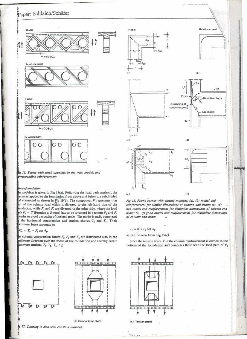
V Framecomer wilh dosing momentThc simple modd in rlg 18(a) is acccptable oll1yü the dimensions of the
. column and bcam do not differ too much anel ü the wholc chordreinforc:ement is bent CClDtinnouslyarouDd tbe comer accxxdiDgto Fig 18(b).
If such a modd is applied aIso to the frame corn~ in F'Jg18(c)withdiffcrcnt chord foRZST2t>7;. not oll1yis the oricntation at the theory ofelasticity rather poor but also cquilibrium is DOmore poss1õlefor theindividual reinforccment bars. as shown in rJg 18(d). .
Instead, the dirrerence of chorei fon:es 4T = li - TI. which isanchored within the depth of the girder. caDsfor horizontal tics TJ,
1;TJ= 4T according to rlg 18(e).(f).
===t3'O4.S(m) A.=Z"4cm2 ti 01-z.s
1'28 iJ-(c)
1'4'F/2.
(a) r-I I . I
1641 I I,
c, 1.
FIZ I'. I \
\
=, I
Cz,\ ..._\ ...
I----;-r \
-tI · '0J)_'J3/
I T2,
\
-\ 1- I . !
/ \ I
\I C34
I
I/ I \ ...'"
/ \ 1 \2
\/ \J0=69" TI.,.'"
F/2 JI. I--;f-
c='O
1 ---J-
(d)
Fig /5. Deep beam: (a) lesled spec;men W121.; (b) modelor;entaled. aI lhe Iheory of elast;city; (e) crack patlem from lesl; (d) model(b) adjusled to lhe fa;lure mechanism
~aper: Sch1aichlSchãfer
Modd
r
rttt.~
t ~t
I
d16. Betzms wilh smaU openings in lhe web: models and
Inding reinlorcemenl
~k-foundiztion,e problem is given in F18 19(a). Following the load path method, the
applied to the foundation from above and below are subdividedCODDcctedas shown in Figl9(b). The component F; representS thator the column 10ad w1rlch is divened to the left-hand side or the
ndation. while F2 and F. are divened to the other side. where the load~ = T (forming a U-turn) has to be arranged in between Fz and F.
order to avoid a c:rossingof the load paths. The mode! is easily completedthe horizoDtal compression and tension chords Co and To. Their° .um force amounts to
C. = T. = I=;cot 6..
co1umi1compression forces 1=;.F2 and F. are distributed a1so in the- 'etSe dircctiOD over the width of the foundation and thereby acate
tension. 7j. T2. T.. e.g.
~r °-,--'-r-r-°--r-°,. 1 ~-4.. '
I
I /,I
. I / '.
i iío! i
"
I t )"I \ /
. I 't--<f .L I I I J.L-..1 I-. --L-.
~
. ~ ~ ~ ~
1
: O Jl je~ b' ~ ~ ~1-~
~ (b) Comprwssion ChOn:I
t, 17. Opening in slab wilh COnslant moment~I>
j
MoeXI
!--f", ~
'R' h
''t---l.- 4zs4 O'~fccI
-JJ .1 O'~fCd
t-h+(o)
-1 I 1,
\\\\\\
li- t
12=31,
(c)
T,loS':\=;
,,'-c)~TJ J---'5'1vr-C]
" ~TJ
't~I1I.
__J..!..
tC2
..~
T2
(e)
.------
~:JJ"1
, II
_ri(b)
[.1.
i,IIInI
[JIIII
IjI.
Cradc
Fig /8. Frame eom:!f' with closing moment: (a), (b) model andreinlorcemenr lor similar dimensions 01 column and betJm; (eJ, (dJbad model and reinlorcemenllor dissimilar dimensions 01 column andbeam; (eJ, (/) good model and reinlorcemenllor dissimilar dimensions fof column and beam
r. = 0-5 Fi cot 62,
as can be secn from Fig 19(<:).
Since the tensiOD force T in the column reinforc:ement is c:arried to the
bonom of the fOundatiODand combines there with the load ~ of FJ
~.ro . o 01
101/ \ -
Lo .- .. .J
~(cJ Tcnsion c:tIorO
T1.._ ,...
I
I
II I
III
. (Spalling of
conactc COI/Cr)11 '.,\-Sa mockl
,. - [i
(d)
IT, TVI I
I I..
! 1I--"
_J'c,
(f)

Paper: SchlaichlSchãfeJ ~
~-m
-T~m I
I~I~II
m-m
(d)
m-m Loops
..-?jI J.J-~,
~6H'2
"
TJ
(c)
." 19. BIocJcfoundal;on: (a) lI1youl and applied forces; (b),~ SlI'III-4UUl-t;e modeJs; (d) corresponding re;nforcemenl; (e) model
'éWlhe distribulion of lhe horizonllll forces AH and combined'On:emenl if lhá model á applied
tbe widtha of thc.column, its contribution to the tensi1ediord To
AlI - FJcot 6J,
be anaqcd within this width as we1l,e.g. by horizontallegs of theRÍlÚon;cment(F1g19(d». .
O Structural Englneêr/Volump. r;o/'/\Jn r:./10 U h 1001
~~ ,-O'
,T, ..;'1If';--~, \ '...-O'I \ "I TJ\ ,, , I \ ~ ~-
~(ti)
Tzl2 Rcinforccma1t
W2 WI
Tzl2
(e)
Fig .20. Hole fOOlings: (a) model for a fool;ng w;th rough jo;nts;(b) model for a fool;ng .wilh smooth jo;nts; (e) simplijied model forlhe wa/Is in horizonlal projeclion and eorresponding reinforcement
These legs can be avoidcd and the longitudinal reinforc:ement can beevenly distributcd over the whole foundation width if, in accordance withFig. 19(e), the additional U'aDSVer5etc:nsion
TJ =0'5 fJ{ cot'.is ~ covercd by rt:inforc:ement. Loops would be necessary in this casefor the anchorage of the column reinforc:ement T near the bottom of thefoundation. .
AR tcusile forces havc to be covered by reinfora:ment. 1be reinforc:ement
for To must be eX1endcdto the left end of the foundation and theU'aDSVer5ercinforc:ementfor TI' T:z-TJand T.over the wholewidth. Nohooksare nec:essaryfor betteranchorageofhorizoDWbars ir approJãmatdytWo-thirdsof the neccssary anchorage ~ of the Code is provided'behind' the nodes of the model.
The compressionstrut Conec:dsno speáal dicck, ir the compressionnode immediatelybelow the column is assumeddeep enough (seetypicalnode m, Fig 10).
.-
D1I
iI
i1jI
~.
L.1per: Schlaich/Schãfer
~~~.Fig 21. Ú1YOUIof a cable bridge for pedeslrians in 5111ugart
I ir i1I I
-1-,
-+- . c5o4
OKmi ~~.? IJII
+.~.II
II
'-+I
I0":1
II 6:?
1--'I
I
I
+-
I
I
FIg 22. Rejected proposo/s for lhe anchorage of lhe cables in lhebridgedeck (delailA of Fig 21) .
HoIe foolingsIn FIgS2O(a)and (b) models are givcn for two cases. In the fU'Stcase. rough(profiled) CODcretesurfaais are assumed for lhe joint of column andfOUDdationando ia lhe od1er. smooth surfaces wllic:hdo DOtpermit aDÍIIcIinedSUUt to c:ross~ioint ~.,.\ol ~"" ! ,": '}
Ifchejoint is rougtr/(Fag2O(a».1bc column de TisoYC:dapped via indiDcdCIOIDpressioDC. with vCniCãl ties TI in lhe fooc:ing~Uereby horizontalfOResare app1ied to the footing walIs WI ~ W2. whic:hmust betransferred latera11yimo the side walIs. as e.g. shown in Fag2Oíc)by a Vt:rySÍII1pIifõedmodd. The waUsWl and W2 em. ""'P-'iD8 ODthcir s1c:Ddcmess.also be treated like shem beams followiDg the Code. The ties Tzl2 ia tíüslDOdd correspond to the horizontal tie T! in Fag 2O(a). Ucir forces canbe COveredby horizontal n:inforcement on both lhe inner and outcr sidesof lhe foundation side walIs. ir lhe modd is adjusted accordingly.
.....
II
I I~-t- -
III
-1
'r---~--+ --}
J ~./'
- ---J(a)
171-1
I
II
~.IIII
t-T--l
"IrT--j. .=t=I--:- -=.it-I- --~
/ )..J__-I/1 / _..L-~
~ ~I
(b)
Caststul
II.I"II
. Rcinfo1"cCmcnt
(e)
Fig 23. Anchorage of lhe cableforces (delail A Df Fig 21): (a) basicmodel of lhe forces in lhe bridgedeck and correspondingslressdislribulion; (b) re/ined modeJ;(e) casl steeJcomponenlS andreinforcement according 10 model (b) .
.The vertical tie force r. is dc:viated.iato the lower 1ayer of n:inforceD1em
of the foundation 1i1cethe chord in a frame comer. It balances there withthe forces proceerling fcom the column.s compression chord.
Ue modd for dae foundation with smooth j~ (Fag 2O(b» leads toapproximatdy 1.7 times 1arger horizontal forces T! and an acktiÜonaltensi1e force r. of similar magDitude ia lhe side wa1ls. Also d1e diagona1compression forces õ.othe colWDJ1and wans are increased acc:ording1y.
1bese examples sbow the uscfulness of SUUt-and-âe modds DOtoo1y fordimensioning but also for dae conceptual design of a struCtUrCor detail.This will be shOWDmore dearly ia lhe next cxamp1e.
Detail Df a pedestrian bridgeFag 21 gives an impression or a cab1ebridge ia Stuagan. which is suspeudedfrom an cxisting building. We shal1 devdop a dcsign of the Dodes wherethe cables ~ anchored aDd introduce thcir horizootal forces into theconcrete bridge dec".
The Structural Engineer/Volume 1i9/No.6/19 March 1991

..
Paper: SchlaichlSchãfe
Pre1iminary proposals for tbis detàiI using $Icei girdcrs embedded in theconaete (Flg 22) were rejcaed after the strut-and-tie model (Fig 23(a»showed how the c:ableforces could be iauoduced immediatdy without anybending of embedded members and the associated high stresses anddeformations. The compression forces are applied dircctly in the directionof the diagonal modd strUtS via profiled cast:.stcel components withoutmajor disturbance of the thin conaete dec:k (Fig 23(c». Transversereinforcing bars, wdded to the cast stecl components, carry the tie forcesof the modelo The stress distribution is further improved by smearing thenade A over a greatc:r Ic:ugth.as suggested by the rdincd model of Fig 23(b).
The cbec:k of the conaete compression stress applied by the cast $Iceineeds no further exp1anation.
Ir the cab1es are incIined ai a considerable angle ia order to suppon thebridge dec:k, as is usuaUy the case, a banom fJange mUst be attached tolhe $Icei member for vertical suppon of the dec:k.
CoaclusioasStrut-and-tie models can be used for tracing the internal forces incomplicated details. Thcy are very helpful in the conceptual desiS!Lof a . .:;de:ail, leadiag the designer intuitively to simple and souncHÕÍuti;)iis. ....Strut-and-tie models are also a basis for thc quantitative chec:k of detailsand whole structures. However, the method also rcquires some enginecringknowledge and training to whicb tbis paper is intendcd to contribute witha SUt1U1WYof principies and a few applications of the method.
Refereaces1. Schlaich,J., Scbãfer,K., Jennewein,M.: 'Towarda consistentdesign
of struaural conaete', PCI Joumal, 32, No.3, May-June 1987,pp74-ISO
2. Ritter, W.: 'Die BauweiseHennebiquc'. (rbe Hennebiquesystem).SchweizerischeBauzeitung. Bd. XXXIII. No.1~January 1899
3. Mõrsch. E.: Der Eisenbetonbau, seine Theorie und Anwendung'(Reinforced conaete, thcory and application). Stuttgart, VerlagKonrad WittWer, 1912
4. Leonhardt, F.: 'Reducing the sbear reinforcement ia reinforcedconcrete beams and slabs', Mag. Concrete Research, 11, No.53.Deccmber 1965,pl87
5. Rüsch. H.: 'Über dic Grenzen der Anwcndbarkeit derfachwerkanalogie hei dcr Berechnung der Schubfestigkeit vonStahIbetonbaiken' (On thc limitations of applicabilityof the trussanaIogy for the shear dcsignof RC beams), FesrschriftF. Ozmpus'Amid et Alumni', UDiversitéde Liêge, 1964
6. Kupfer, H.: 'Erweitcrungder Mõhrsch'schenfachwerkanalogicmitHilfe des 'Primips vom Minimum der formãnderungsarbeit'(Expansionof Mõrsch's truss anaIogybyapplicationof the principieof minimum strain energy), CES Sulletin, 40, Paris 1964 /1. Thürlimann, D., Marti, P., Pralong, J., Ritz, P., Zimmerli, D.:'Vorlesung zum fonbildUDgSkursfür Bauingenieure' (Advancedleaurc forCivil Engincers),Institutfür Bautcdmikund KonstruIaion,ETH Zürich 1983(see further referencesthere)
8. Marti, P.: 'Basic tools of reinforced conaetc bcam design', AC!Joumal, January-february 1985,pp4ó-5~
9. Mue1ler,P.: 'Plastische Bercchnung von StahlbetonscheibeoundBalken' (plastic ana1ysisof reinforced conaete deep beams andbeams),BeridIlNo. 83, Institutfür Ba"motilrundKonsuuJction,ETHZürich, Jo1y 1978
10. Collins, M. P., and Mitcl1e1l,D.: 'Shear, and tomon design ofprestressedand ooo-prestressedconcrete beams', PC! Joumal. 25,No. 5, September..Qaober1980,pp32-100
11. Schlaich, J., and Weischedc,D.: 'Eia praktisches Verfahren zummethodisc:benBemessenund Konstruieren im Stahlbetonbau' (Apraaica1 mcthod for thedesignand detailingof structUralconc:rete),Bu/IeJind'!nfomuztJonNo. ISO,Paris, ~ Euro-IntcmationalduBéton. March 1982
12. SchIaic:b.J.. anelScbãfer,K.: Konstruierenim Sllzhlbetonbml(Designand detailing of structura1conaetc), BctonbIender 1984, Part li,w. Emst &.Sobn, BerIin-Müncben,pp187-IOOS(reviscd versioapublishe:lin the BctonbIencta: 1989) .
13. Zdler, W.: cBruchYerSUchean Stahlbetonkonsolen bei Verãnderungdes Bewebrungsgrade', (Failurc tcsts 00 RC corbds wid1 diffcrentreinforcement railos), AbsdrJu}Jberidrt zum Forscluurgsvorluzben,Institut für Massivbau uad Baustoffteclmo1ogie, UaMrsitãt fCar.Isruhe,1983 .
14. Lconhardt; f., and WaIther, R.: 'WandartigC Trãger., (Dccp beams),DAfStb. Heft No.178, Berlin, W. Emst &.Sobn, 1966
_1 yo:.__: '''IY_1 ,,,. _ ,__ ..,