Embed Size (px)
Citation preview

Sonoma County Water Agency
DESIGN AND CONSTRUCTION STANDARDS FOR SANITATION FACILITIES
2009 Update Approved: February 3, 2009
Sonoma County Water Agency
404 Aviation Boulevard Santa Rosa, CA 95403
707-526-5370 \\fileserver\data\techw\special projects\sanitation design standards\_sanitation design standards revised 2008\final.doc 3/27/2009

Design and Construction Standards for Sanitation Facilities – 2009 Update Approved: February 3, 2009 i
DESIGN AND CONSTRUCTION STANDARDS FOR SANITATION FACILITIES
TABLE OF CONTENTS PAGE
SECTION 1 – ABBREVIATIONS, DEFINITIONS, AND TERMS ..........................................1
1.1 GENERAL ............................................................................................................................1 1.2 ABBREVIATIONS AND ACRONYMS .........................................................................................1 1.3 DEFINITIONS AND TERMS .....................................................................................................2 1.4 ADDITIONAL DEFINITIONS AND TERMS .................................................................................9
SECTION 2 – GENERAL INFORMATION..............................................................................9
2.1 DESIGN AND CONSTRUCTION STANDARDS FOR SANITATION FACILITIES INTRODUCTION...........9 2.2 SANITATION CODES .............................................................................................................9 2.3 ANNEXATION ....................................................................................................................10 2.4 RIGHT-OF-WAY POLICY AND SUBORDINATION.....................................................................10 2.5 CONDEMNATION POLICY ...................................................................................................11 2.6 ENVIRONMENTAL REVIEW UNDER THE CALIFORNIA ENVIRONMENTAL QUALITY ACT ............11 2.7 MAINTENANCE OF SIDE SEWER ...........................................................................................11 2.8 MAINTENANCE OF BACKFLOW PREVENTION DEVICES ..........................................................11
SECTION 3 – GENERAL REQUIREMENTS ..........................................................................12
3.1 GENERAL REQUIREMENTS ..................................................................................................12 3.2 SEWER DESIGN CAPACITY AND STRUCTURAL CALCULATIONS ...............................................12 3.3 SIZE OF PLANS AND DATA REQUIRED ..................................................................................13 3.4 SANITARY SEWER EASEMENTS ............................................................................................15 3.5 FLOOD CONTROL APPROVAL ..............................................................................................16 3.6 GEOTECHNICAL INVESTIGATION .........................................................................................16 3.7 OTHER AGENCY APPROVAL ...............................................................................................17
SECTION 4 - DESIGN STANDARDS....................................................................................17
4.1 DESIGN CRITERIA ..............................................................................................................17 4.2 SEWER PIPES......................................................................................................................18 4.3 SEWER STRUCTURES ...........................................................................................................24 4.4 ACCESSIBILITY ...................................................................................................................26 4.5 PUBLIC PUMP STATIONS .....................................................................................................26 4.6 PRIVATE INDIVIDUAL PUMP STATIONS ................................................................................27
SECTION 5 - PLAN APPROVAL AND PERMIT ISSUANCE ...............................................29
5.1 GENERAL ..........................................................................................................................29 5.2 PLAN CHECKING FEE .........................................................................................................29 5.3 PRELIMINARY REVIEW........................................................................................................29 5.4 FINAL REVIEW AND APPROVAL...........................................................................................30 5.5 CHANGED CONDITIONS .....................................................................................................30 5.6 STATEMENT OF FEES AND CHARGES ....................................................................................30

Design and Construction Standards for Sanitation Facilities – 2009 Update Approved: February 3, 2009 ii
5.7 ISSUANCE OF THE PERMIT ...................................................................................................30 5.8 SUBDIVISIONS ....................................................................................................................31 5.9 ITEMS TO CONSIDER BEFORE SUBMITTING PLANS .................................................................31
SECTION 6 - CONSTRUCTION ENGINEERING.................................................................31
6.1 GENERAL ..........................................................................................................................31 6.2 STAKING REQUIREMENTS ...................................................................................................31 6.3 SIDE SEWER LOCATION ......................................................................................................32 6.4 SURVEY AUTHORIZATION AND RESPONSIBILITY ...................................................................32 6.5 RECORD DRAWINGS...........................................................................................................32
SECTION 7 - PERMITS, LICENSES, AND BONDS ..............................................................32
7.1 PERMITS ............................................................................................................................32 7.2 LICENSES...........................................................................................................................33 7.3 BONDS ..............................................................................................................................33
SECTION 8 - CONTROL OF WORK ......................................................................................33
8.1 REFERENCE STANDARDS AND SPECIFICATIONS.....................................................................33 8.2 CONFORMITY WITH PLANS AND ALLOWABLE DEVIATIONS ...................................................34 8.3 ALTERNATIVE DRAWINGS ..................................................................................................34 8.4 SURVEY WORK BY PROJECT ENGINEER.................................................................................34 8.5 TESTS BY PROJECT ENGINEER ..............................................................................................34 8.6 SALVAGE OF EXISTING MATERIALS......................................................................................34 8.7 CROSSING UNDER RAILROAD, HIGHWAY, OR UTILITIES ........................................................35 8.8 PRESSURE TESTING OF GRAVITY SEWER PIPES.......................................................................35 8.9 TELEVISION INSPECTION.....................................................................................................36 8.10 PRESSURE TESTING OF SEWER FORCE MAINS.....................................................................37 8.11 TESTING OF MANHOLES ..................................................................................................37
SECTION 9 – APPROVED MATERIALS LIST ......................................................................38
9.1 SUBSTITUTE MATERIAL APPROVAL PROCESS ........................................................................38 9.2 APPROVED MATERIALS AND MANUFACTURERS ...................................................................38
SECTION 10 - STANDARD DRAWING LIST.......................................................................47

Design and Construction Standards for Sanitation Facilities – 2009 Update Approved: February 3, 2009 1
SECTION 1 – ABBREVIATIONS, DEFINITIONS, AND TERMS
1.1 General
Whenever in these standards, or in any documents or instruments that these standards govern, the following abbreviations, or definitions are used, the intent and meaning shall be interpreted as follows.
1.2 Abbreviations and Acronyms
Additional abbreviations are contained in Section 1-3 of the Standard Specifications for Public Works Construction (Standard Specifications) and in the applicable Sanitation Code which shall apply to all work. AAN American Association of Nurserymen AASHTO American Association of State Highway and Transportation Officials AB Aggregate Base ABS Acrylonitrile-Butadiene-Styrene ACI American Concrete Institute AREA American Railway Engineering Association ANSI American National Standards Institute ASA American Standards Association ASCE American Society of Civil Engineers ASTM American Society for Testing Materials AWPA American Wood Protection Association AWS American Welding Society AWWA American Water Works Association CEQA California Environmental Quality Act CIP Cast Iron Pipe CIPP Cured-in-Place Pipe CISPI Cast Iron Soil Pipe Institute CLCSCP Concrete Lined and Coated Steel Cylinder Pipe CLSCP Concrete Lined Steel Cylinder Pipe CMP Corrugated Metal Pipe CPC California Plumbing Code CSD(s) County Sanitation District(s) DIP Ductile Iron Pipe ESD Equivalent Single-Family Dwelling Unit FEMA Federal Emergency Management Agency HDPE High Density Polyethylene I&I Inflow and Infiltration IAPMO International Association of Plumbing and Mechanical Officials Inv. Invert Elevation LAFCO Local Agency Formation Commission MH Manhole NACE National Association of Corrosion Engineers NEC National Electrical Code

Design and Construction Standards for Sanitation Facilities – 2009 Update Approved: February 3, 2009 2
NEMA National Electrical Manufacturers Association NSF National Science Foundation OSAA Outside Service Area Agreement PRMD Permit and Resource Management Department PVC Polyvinyl Chloride Pipe RPMP Reinforced Plastic Mortar Pipe S Pipe Slope (foot of vertical drop per foot of horizontal distance) Stl. P Steel Pipe Std. Dwg. Standard Drawing SZ Sanitation Zone UBC Uniform Building Code UPC Uniform Plumbing Code URB Untreated Rock Base WSP Welded Steel Pipe
1.3 Definitions and Terms
Other definitions exist in the Sanitation Code and in the Uniform Plumbing Code and other places. Where the definitions in these Design and Construction Standards for Sanitation Facilities conflict with the definitions in the Sanitation Code, or in the Uniform Plumbing Code, or other document, the definitions in the Sanitation Code shall prevail, then the definitions in the Design and Construction Standards for Sanitation Facilities, and then in other documents.
Acceptance - Formal acceptance by action of the Board of Directors of the Agency or a District, or by the General Manager/Chief Engineer where authorized by the Board of Directors of the Agency or District, on an entire contract or agreement or work completed in all respects under permit in accordance with the plans and specifications and any modifications thereof previously approved. Agency - Sonoma County Water Agency, including the Sanitation Zones, as applicable. In addition, the Agency acts as operator of the County Sanitation Districts, as defined under "Districts" below. Agency Office - Sonoma County Water Agency office located at 404 Aviation Boulevard, Santa Rosa, California 95403. Agency Standards – See "Design and Construction Standards for Sanitation Facilities." Annexation - The inclusion of property within a County Sanitation District Service Area Boundary or a Sanitation Zone Service Area Boundary by proper legal procedures. Approved by the Agency - Approved by the Sonoma County Water Agency's General Manager/Chief Engineer, acting on behalf of the Agency or a District, or by the designated representative of the General Manager/Chief Engineer. Board of Directors - The governing Board of Directors of the Sonoma County Water Agency, the Occidental CSD, Russian River CSD, South Park CSD, or the Sonoma Valley CSD.

Design and Construction Standards for Sanitation Facilities – 2009 Update Approved: February 3, 2009 3
California Plumbing Code - The California Plumbing Code (CPC), current edition, adopted by the State of California and the County of Sonoma, a copy of which is on file in the Agency's office for use and examination by the public, except such sections therein as are shown to be omitted, amended, or added thereto, in said copy. Wherever the term "Administrative Authority" is used in the CPC, it shall be construed to mean the Agency's General Manager/ Chief Engineer. Caltrans Specifications - The Standard Specifications of the State of California, Department of Transportation (Caltrans), current edition. Where the terms "State" or "Engineer" are used in the Caltrans specifications, they shall be considered as meaning the Agency as defined herein. City - Any incorporated municipality in the County of Sonoma. Class "2" Concrete – Concrete with 590 pounds of cementitious material per cubic yard in accordance with Caltrans Section 90 "Portland Cement Concrete." Cleanout – A piped structure conforming to Agency Standards with a removable cap or cover installed at the upper end of a Main Sewer, at the edge of right-of-way for a Lateral Sewer, and in the on-site Building Sewer, which provides access to the sewage collection system for the purposes of testing, inserting tools for cleaning and removing blockages, testing, and video inspection. Contractor - Any individual, firm, corporation, partnership, or association duly licensed by the State of California to enter into contracts to perform the permitted work of installing Sewerage Works, or the owner(s) of private property constructing permitted Building Drains or Building Sewers or other Sewerage Works only on their own private property. County - The County of Sonoma, State of California. County Sanitation District Service Area Boundary - The County Sanitation District Service Area Boundary as set by the County Sanitation District and LAFCO. County Sanitation District Sphere of Influence – The probable ultimate physical limits and service area of the County Sanitation District as set by the County Sanitation District and LAFCO. County Sanitation District Urban Services Area Boundary – The designated limit to the urban development of the County Sanitation District as set by the County of Sonoma Board of Supervisors in the Sonoma County General Plan. Design and Construction Standards for Sanitation Facilities –This set of documents containing design and construction standards for all sanitation works of the Agency, dated December 16, 2008, together with subsequent amendments. Design Engineer – See Project Engineer. District(s), or Sanitation District(s), or County Sanitation District(s) – Occidental CSD, Russian River CSD, South Park CSD, or the Sonoma Valley CSD. The Districts are each separate legal entities formed under the California Health & Safety Code, Section 4700 et seq. The Districts are operated by the Agency.

Design and Construction Standards for Sanitation Facilities – 2009 Update Approved: February 3, 2009 4
Encroachment Permit – A written authorization issued by the State, County, or City which allows the Agency or District to excavate, install, repair, replace, remove, re-construct, operate, maintain, access, and use a public sewer facility within an area over which the State, County, or City has jurisdiction. Equivalent Single-Family Dwelling Unit (ESD) – Any structure constructed for occupancy of one single family. This classification includes trailers and mobile home units with connections to the Agency or District Sewer System. Geotechnical Engineer – A California Registered Professional Geotechnical Engineer or California Registered Professional Soils Engineer. Granny Unit – See Second Dwelling Unit. Infiltration – Water entering the sewer system from the ground through such means as pipes, pipe joints, connections, or manhole walls. Inflow – Water entering the sewer system from surface sources such as manhole covers, open cleanouts, yard or basement drains or roof drains. Interceptor – An Agency-approved precast or cast-in-place concrete, high-density polyethylene, coated steel, or other plastic containment device designed to intercept, trap, or otherwise prevent grease, sand, flammable liquids, or other substances potentially harmful to the sanitary sewerage system from entering said system. Inspector - The engineer or technical inspector(s) duly authorized or appointed by the Agency and responsible for the particular duties delegated to the inspector in writing. Living Unit – A structure containing a kitchen or electrical wiring and/or plumbing for potential use of a kitchen. Manhole – A sewer structure designed and constructed in conformance with Agency Standards which provides access to the sewage collection system for purposes of cleaning, removing blockages, sampling, and video inspection. On-Site – Located on private property outside of public right-of-way. Ordinance(s) – See "Sanitation Code(s.)" Outside Service Area Agreement (OSAA) – An agreement to allow sanitary sewer collection facilities to be extended to serve a parcel outside a County Sanitation District Sewer Service Area Boundary or a Sanitation Zone Service Area Boundary by proper legal procedures. Outside Sewer – A Sanitary Sewer which extends beyond an Agency Sanitation Zone Service Area Boundary or a County Sanitation District Service Area Boundary. Owner - In the case of the Agency or applicable District projects, the term Owner shall mean either the Agency or the applicable District. In the case of private projects, including also

Design and Construction Standards for Sanitation Facilities – 2009 Update Approved: February 3, 2009 5
projects for mobile home parks and public schools, the term owner shall mean that person who is doing or having work done under permit or agreement with the Agency or applicable District or that person's authorized representative. All public Main Sewers, Trunk Sewer Mains, I & I Trunk Sewer Mains, Lateral Sewers, and other public sewage works installed under the Agency's or Districts' Sanitation Ordinances shall immediately become the sole property of the Agency or District upon installation and final inspection and acceptance by the Agency or District. All private on-site building drain sewers, building sewers, mobile home park sewage works, and public school sewage works, installed under the Agency's or District's Sanitation Ordinances shall remain the sole property of the owner as defined for private projects unless otherwise stipulated in a written agreement between Agency or District and owner. Permit - The written authorization required pursuant to the Ordinances, rules and regulations of the Agency or applicable District, prior to the installation or construction of specific sewage works under specific conditions at specific locations, or the use of any public sewers. Permittee – A person to whom the Agency or a District has issued a permit for sewer construction or use. Permit and Resource Management Department – Sonoma County Permit and Resource Management Department, located at 2550 Ventura Avenue, Santa Rosa, CA 95403 (Phone: 707- 565-1900). Plumbing Fixture Units – Fixture unit load values for the sizing of drainage piping and building sewers, computed from Section 703.2 and Tables 7-3 and 7-4 of Chapter 7 of the California Plumbing Code (most recent County-adopted version); however, minimum building sewer size shall be four (4) inches in diameter. Plumbing System - All plumbing fixtures and traps, or soil, waste, special waste, and vent pipes, and all sanitary sewer pipes within a building and extending to the building sewer connection two (2) feet outside the building foundation thereof. Potholing – Uncovering of existing underground utilities by a method that will ensure the utility is not damaged or impacted in order to determine the exact horizontal and vertical location of the utility. All digging methods within 2 feet horizontally or vertically of any existing underground utility shall use hand digging methods. Privately Financed Construction or Privately Financed Projects - Projects involving construction of sewerage facilities that are intended to become public facilities, other than Agency or District financed projects, shall be designed and constructed in accordance with Agency Standards and connected to the Agency or District sewerage system under permit or agreement with the Agency or District. Project Engineer - The Professional Engineer licensed by the State of California as a Civil Engineer, under whose direction plans, profiles, and details for the work are prepared, stamped with the Engineer's Stamp, signed by the Engineer, and submitted to the Agency for review and approval. Public Right-of-Way – An interest in a strip of land allowing the Agency or applicable District to pass over the land of another for purposes related to sewer pipelines.
Design and Construction Standards for Sanitation Facilities – 2009 Update Approved: February 3, 2009 6
Public Road/Street – A road or Street open to public travel in which an ownership interest of the State of California, the County of Sonoma, or a City exists, and which is maintained by said State, County, or City, and in which the Agency or applicable District is allowed to excavate, install, repair, replace, remove, re-construct, operate, maintain, and use public sewer works within the public road/street by permit. Public Sewer Easement – An interest in land owned by the Agency or a District consisting of, but not limited to, the right to excavate, install, repair, replace, remove, re-construct, operate, maintain, and use sewers on private or public property for public use. Said right typically includes the right to ingress and egress over the private or public property encumbered by the easement to facilitate the rights owned by the Agency or applicable District. Reach - The section of a Main Sewer between manholes or between a manhole and a cleanout. Record Drawings - Reproducible plans, signed and dated by the Project Engineer and the Agency's/District's representative, and an electronic copy thereof in a format approved by the Agency, indicating that the Agency-approved plans have been reviewed and revised, if necessary, to show the actual location of all main sewers, structures, wyes, lateral sewers, cleanouts, pump stations, and other sanitary facilities that have been filed with the Agency or District before final acceptance of the Sewage Works. Roof Drain – A drain designed to collect rainfall from a building roof. Sanitation Code(s.) - The Agency's and/or Districts' Sanitation Code(s) including any and all amendment(s) thereto. Sanitation Zone(s) – Airport/Larkfield/Wikiup SZ, Geyserville SZ, Penngrove SZ, Sea Ranch Central SZ, and Sea Ranch North SZ. The Sanitation Zones are owned, operated, and maintained by the Agency. Sanitation Zone Service Area Boundary - The Sanitation Zone Service Area Boundary as set by the Agency and the Sonoma County General Plan. Sanitation Zone Sphere of Influence – The probable ultimate physical limits and service area of the Sanitation Zone as set by the Agency and LAFCO. Sanitation Zone Urban Services Area Boundary – The designated limit to the urban development of the Sanitation Zone as set by the County of Sonoma Board of Supervisors in the Sonoma County General Plan. Second Dwelling Unit - A detached, second living unit on a single parcel in undivided ownership with a size less than or equal to 840 square feet, or as otherwise determined by the PRMD, Planning Section, in accordance with the Sonoma County General Plan. Section – Any reference to a section that is not accompanied by further reference refers to a section or sections of these Design and Construction Standards for Sanitation Facilities.
Design and Construction Standards for Sanitation Facilities – 2009 Update Approved: February 3, 2009 7
Sewers –
Building Drain - That part of the lowest piping of a drainage system which receives the discharge from the Plumbing System pipes inside the foundation of the building and conveys it to the building sewer, which begins two (2) feet outside the building foundation.
Building Sewer - That portion of any sewer beginning at a point two (2) feet outside the foundation line of any building and running to the property line, public road/street right-of-way line, sewer easement right-of-way line, or to a private sewage disposal system.
Collection System – The Agency's or a District's sanitary sewers, pump stations, sample locations, manholes, cleanouts, and other similar facilities lying within a public road/Street right-of-way or public sewer easement which accept, collect, and convey sanitary sewage to the Agency's or applicable District's treatment plant, or by agreement discharge to the collection system of another agency responsible for treatment.
I & I Trunk Sewer Main – A Sewer Main to which no Collection System may be connected. This Sewer Main is used strictly for bypassing excess flow within the Trunk Sewer Main.
Lateral Sewer - That portion of the sewer connecting a building sewer to the main sewer which is owned by the Agency or County Sanitation District but maintained by the private property owner and lying within a public road/Street or public sewer easement.
Main Sewer - A public sewer lying within a public road/Street or public sewer easement designed to accommodate one or more side sewers and for which suitable access can be provided for maintenance reasons at the sole discretion of the Agency or appropriate District.
Mobile Home Park Sewer – An on-site private sewage collection system under the jurisdiction of the State of California Department of Housing and Community Development which connects to a Main Sewer at a public sewer manhole within a manhole in a public right-of-way or public sewer easement.
Private Main Sewers –
1. Those on-site main sewers for which adequate access cannot be provided for public maintenance purposes at the sole discretion of the Agency, and which serve multiple buildings on a single parcel or multiple parcels, and for which there is an existing contract between the Agency or appropriate District and the responsible owners' association representing the multiple buildings or multiple parcels.
2. Those on-site main sewers for Mobile Home Parks or Public Schools that are under the jurisdiction of the State of California Department of Housing and Community Development or the State Division of Architecture, respectively.
Public Sewer – Main Sewers and Lateral Sewers lying within public roads/Streets, or within public sewer easements and which are directly controlled by, or under the jurisdiction of, the Agency or a District.
Sanitary Sewer or Sewer – A pipe or conduit which carries sewage and to which storm water, surface water, and groundwater are not intentionally admitted.
Sewer System or Sanitary Sewer System – Main Sewers, Laterals Sewers, pipes, manholes, cleanouts, or any other appurtenance which facilitates the flow of waste or wastewater to the treatment plant.

Design and Construction Standards for Sanitation Facilities – 2009 Update Approved: February 3, 2009 8
Sewage Works or Sewerage – All facilities for collecting, pumping, treating, and disposing of sewage or wastewater.
Side Sewer - The side sewer consists of all piping included in the privately owned building sewer and the publicly owned lateral sewer.
Trunk Sewer Main – A Main Sewer to which no Lateral Sewers are allowed to connect. Only Main Sewers can connect to a Trunk Sewer Main. All connections to a Trunk Sewer Main shall be at a manhole.
Soils Engineer – A California Registered Professional Soils Engineer or California Registered Professional Geotechnical Engineer. Special Provisions – Any provisions in an Encroachment Permit from an agency of jurisdiction which supplement or modify the Standard Provisions of the Encroachment Permit or these Agency Standards. Standard Drawings - The drawings of structures or devices commonly used on Agency sanitation work adopted by the Agency as Standard Drawings. Standard Specifications - The words "Standard Specifications" mean the Standard Specifications for Public Works Construction, current edition, in its entirety, prepared by the Southern California Chapter of the American Public Works Association and Associated General Contractors of California, and published by Building News, Inc., Box 3031, Terminal Annex, Los Angeles, California 90051. This is also known as the "Greenbook." Street - Any public highway, road, street, avenue, alley, way, public sewer easement, or public right-of-way used by, or to be used for, vehicle movement and for access to public sanitary sewer systems. Surety - Any firm or corporation executing a surety bond or bonds payable to the Agency, securing the performance of the contract or permit either in whole or in part. Treatment Plant – Any facility owned, operated, and/or maintained by the Agency and/or District, and/or other agency that is designed to provide treatment of wastewater. Traveled Way - That portion of the roadway for the movement of vehicles, exclusive of shoulders and auxiliary lanes. Uniform Plumbing Code – That certain edition of the Uniform Plumbing Code (UPC) adopted by the Western Plumbing Officials Association and the County of Sonoma, a copy of which is on file at Agency's office for use and examination by the public, except such sections therein as are shown to be omitted, amended, or added thereto, in said copy. Wherever the term "Administrative Authority" is used in the UPC, it shall be construed to mean the Agency's General Manger/Chief Engineer. Yard Drain – A system designed to collect and drain storm water runoff away from a property.

Design and Construction Standards for Sanitation Facilities – 2009 Update Approved: February 3, 2009 9
1.4 Additional Definitions and Terms
Additional definitions and terms shall have the meanings indicated in the most current Sanitation Code and the most current CPC and UPC as adopted herein.
SECTION 2 – GENERAL INFORMATION
2.1 Design and Construction Standards for Sanitation Facilities Introduction
These Design and Construction Standards for Sanitation Facilities or "Agency Standards" consist of guidelines and requirements for the design and construction of sewerage facilities. This document is not to be considered complete nor is it a substitute for the requirements of the Sanitation Codes, or other applicable laws. Should any conflicts arise between the information contained herein and the Sanitation Codes, the information contained within the Sanitation Codes shall govern. In addition, both the Sanitation Codes and these Agency Standards often contain information and requirements on the same subject. The reader is cautioned to consult both these Agency Standards and the Sanitation Codes on each subject matter, and to be aware of other laws or requirements that may be applicable. The Agency owns 5 Sanitation Zones and operates 4 County Sanitation Districts as follows: • Airport/Larkfield/Wikiup Sanitation Zone • Occidental County Sanitation District • Geyserville Sanitation Zone • Russian River County Sanitation District • Penngrove Sanitation Zone • Sonoma Valley County Sanitation District • Sea Ranch Sanitation Zones
(North and Central) • South Park County Sanitation District
Ownership and/or operational control includes the entire sewage works and its appurtenances from the point of connection with the building drain to the discharge terminus of the final disposal or use. The Agency operates and maintains the Districts under contract with each individual District. The Agency owns, operates, and maintains the Sanitation Zones. The term "Agency" is understood to mean the Sonoma County Water Agency, including the Sanitation Zones. Maps showing the existing Sanitation Zone and County Sanitation District boundaries are available for inspection at the PRMD Planning Section Office. All public sewerage facilities constructed or to be constructed within the Agency's operational control, whether privately financed and constructed under permits issued by the Agency or District or publicly financed and constructed under contract with the Agency or District, shall be in accordance with these Design and Construction Standards for Sanitation Facilities, unless otherwise approved by the Agency or District, as well as applicable ordinances, rules, and regulations.
2.2 Sanitation Codes
The Sanitation Codes comprise the rules and regulations of the Agency and Districts pertaining to the construction and use of sanitary sewerage facilities which have been adopted by

Design and Construction Standards for Sanitation Facilities – 2009 Update Approved: February 3, 2009 10
Ordinance. See discussion above for order of precedence, application and interaction of Sanitation Codes and these Design and Construction Standards for Sanitation Facilities. In general, the Sanitation Codes: 1) provide Board policy and authority of the Agency, Agency's General Manager/Chief Engineer and Districts; 2) provide requirements for building sewer and lateral sewer construction and for the use and construction of public main sewers; 3) provide for annexation and Outside Service Area Agreements, plan checking fees, permit fees, and inspection fees; and 4) provide for the establishment of connection charges. It is the sole responsibility of those persons proposing new sanitary sewerage systems to determine and comply with all applicable ordinances, rules, and regulations. Upon request, copies of the Sanitation Codes may be obtained at the Agency Office.
2.3 Annexation
Annexation into a Sanitation Zone or District shall comply with state and local planning area requirements.
2.4 Right-of-Way Policy and Subordination
All public sewage facilities to be accepted by Agency or District (including Sanitary Sewer Systems as defined herein, excluding pump stations) shall be located only within the following areas:
1. Public road(s) and/or street(s) which are dedicated for public use and accepted by the jurisdictional entity (City, County of Sonoma, State) possessing the requisite authority to accept that dedication on behalf of the public. Such public road(s) or street(s) shall be sufficient in width, use, or other physical characteristics which, in the sole judgment of the staff of the Agency, are required for the Agency or District to meet its access, operational, and maintenance necessities.
2. In such cases where dedicated public roads or streets are found by Agency staff to be insufficient for such access, operational, and maintenance necessities as described in Paragraph 1 above, the Agency may require that additional easement area be granted to the Agency or District as prescribed herein as a condition of acceptance of the public sanitary sewer systems by Agency or District. Any such easement shall be in a form acceptable to the Agency and approved by County. In cases where an easement has been previously granted and/or dedicated to the Agency or District or to a predecessor in interest, and such easement does not meet the minimum requirements as outlined in these Agency Standards, the Sanitation Codes or other applicable law in effect as of the date of Agency review of the project, or in a form acceptable to County Counsel or Agency staff, an additional or overlapping easement area as may be required by the Agency shall be granted to the Agency or District as a condition of acceptance of the public sanitary sewer systems by Agency or District.
3. Where mortgages or other liens encumber the property over which the easement is to be grated in accordance with Paragraph 2 above, the Agency will require the Grantor (or Grantor's Agent as applicable) to secure and deliver to Agency staff a duly executed and notarized Subordination Agreement(s) in the form approved by County Counsel prior to acceptance of the public sewer systems by Agency or District.

Design and Construction Standards for Sanitation Facilities – 2009 Update Approved: February 3, 2009 11
2.5 Condemnation Policy
When a public sewer for an Agency Sanitation Zone, District project, or improvement must pass through private property and a Sewer Dedication and Easement Agreement suitable to the Agency cannot be obtained through negotiation with the property owner, the Agency or District may, under certain conditions and at its sole discretion, pursue condemnation of the required easement pursuant to the Agency's or District's enabling authority. The Agency will not pursue condemnation for sewer easements that benefit private developments for any manner other than that approved by law. Private developments must acquire all necessary offsite easement rights prior to obtaining final approval of the project.
2.6 Environmental Review under the California Environmental Quality Act
All Agency and District projects and private developments are subject to the requirements of the CEQA (Public Resources Code Section 21000 et seq.) and the State Guidelines for the Implementation of the CEQA (CFR, Section 15000 et seq.). All Agency and District projects are also subject to the CEQA Implementing Procedures of the Sonoma County Water Agency (Agency Implementing Procedures). Under the Agency Implementing Procedures, the Agency will act as a Lead Agency for Sanitation Zone projects and will prepare environmental documents as needed for Sanitation Zone projects. The appropriate District will act as Lead Agency for District projects. Environmental documents as needed for District projects will be prepared by Agency staff for the District and approved by the District Board. Persons planning private developments should contact the appropriate jurisdictional planning agency early in their planning process to determine the Agency's procedures for compliance with CEQA and the State Guidelines for Implementation of CEQA (the Guidelines). The Agency will review and comment on environmental documents prepared for private developments, within the Agency's or a District's jurisdiction, in the role as a Responsible Agency as required under CEQA, the Guidelines, and the Agency Implementing Procedures.
2.7 Maintenance of Side Sewer
The owner of the property served shall maintain building drains, side sewers (lateral sewer and building sewer), and the plumbing systems, including but not limited to cleaning and clearing of those facilities. Where a side sewer provides service to more than one single-family residential unit in a single building with common walls such as a residential condominium, stock cooperative, community apartment, residential unit with second dwelling unit all on one parcel in undivided ownership, or other similar improvements, or to a commercial condominium with a common side sewer approved and used in accordance with the Sanitation Code, the obligation to maintain the side sewer shall be the property Owner's, homeowners' association, or other entity responsible for the maintenance of the property and facilities owned in common. Replacement or repair of the lateral sewer shall be at the sole discretion of the Agency or District.
2.8 Maintenance of Backflow Prevention Devices
Side sewers within the reach of the connecting main sewer and serving plumbing fixtures located 1) less than one (1) foot above the rim elevation of the nearest upstream manhole or main sewer cleanout, or 2) within the 100-year flood zone shall be protected from backflow of sewage by installing a backflow prevention device in the building sewer in accordance with Agency Standard Drawing 127. The backflow prevention device shall be located on private

Design and Construction Standards for Sanitation Facilities – 2009 Update Approved: February 3, 2009 12
property and shall be installed by the Permittee. The maintenance of the backflow prevention device shall be the sole obligation of the Permittee or Permittee's successor in interest. The Agency shall be under no obligation to ascertain that the backflow device continues in operating condition. The installation of a backflow prevention device shall require a permit from, and shall require inspection by, PRMD.
SECTION 3 – GENERAL REQUIREMENTS
3.1 General Requirements
All engineering plans, specifications, reports, calculations, or other documents shall be in strict compliance with the Professional Engineers Act of the California Business and Professions Code including, but not limited to, being prepared by a registered Civil Engineer (Project Engineer), or by a subordinate employee under the Project Engineer's direction, and being signed by the Project Engineer and stamped with the Project Engineer's seal. Prior to engineering or design work, Project Engineer's shall review any proposed sewer system, extension, and/or existing system change to determine any special requirements or whether the proposal is permissible. The Project Engineer shall also be responsible for determining and locating all other underground facilities in the area of the proposed work by means that may include potholing of critical utilities during the design process as required by the Agency. Approval of preliminary or final plans by the Agency does not in any way relieve the Project Engineer of the responsibility to meet all requirements of the Agency. The plans and specifications for any project shall be revised or supplemented by the Project Engineer at any time it is determined that the full requirements of the Agency have not been met.
3.2 Sewer Design Capacity and Structural Calculations
General - The Project Engineer shall submit two sets of design calculations for Agency review and approval. Design calculations shall be dated, signed by the Project Engineer, and stamped with the Project Engineer's seal. A map showing and identifying proposed sewerage facilities and associated tributary areas, and other information that may be required to describe the proposed project, shall accompany all calculations. • Pipeline Hydraulic Calculations - Sewer Main hydraulic capacity calculations shall be
presented in tabular form and shall include the following information for each reach of sewer:
terminal manhole designation ground elevations at terminal manholes incremental and cumulative tributary areas incremental and cumulative tributary population incremental average and maximum domestic sewage flow incremental infiltration/inflow allowance basis for Peak Wet Weather allowance cumulative design flow invert and rim elevations of manholes length of sewer run sewer pipe size and slope

Design and Construction Standards for Sanitation Facilities – 2009 Update Approved: February 3, 2009 13
calculated existing and proposed sewer pipe capacities and velocities calculated water surface elevation calculated freeboard from calculated water surface to rim elevation at manholes for
existing and build-out conditions • Pump Station Design - Public and Private Pump Stations design calculations shall include:
Site Plan, Profile, Sections, and Details of the pump station and force main. detail of connection of force main to public sewer collection system soils data structural design calculations including sections, details, and all assumptions if cast-in-
place, or manufacturer's wet well structure catalogue cut sheets if pre-manufactured hydraulic calculations including the basis for average and peak flows and all
assumptions including rational for peaking, and inflow and infiltration calculations for wet-well volume including minimum pump cycling time and maximum
pump starts per hour alarm elevations for low-water, pump off, pump on, and high-water levels force main head-capacity curves and individual and combined pump head-capacity
curves plotted on one graph copies of manufacturer's pump head-flow capacity graphs and pump specifications wet-well buoyancy calculations
• Shallow Sewer Mains - Shallow sewer main structural design calculations shall include:
backup data for design method used structural design assumptions structural design calculations trench sections
3.3 Size of Plans and Data Required
Sheet sizes for plans for all sanitary sewerage facilities shall be 24 inches by 36 inches, and shall include as a minimum the following information and data.
A. General - Each plan shall show the name of the project, subdivision, or main extension; sheet number; and total number of sheets. Each sheet shall bear the signature and registration number of the Project Engineer. Each sheet shall have a north arrow, match lines indicating adjoining sheet numbers, and appropriate scale or scales indicated thereon. The lettering for all notes, data, etc. shall be a sans serif font no smaller than 0.12 inch in height.
B. Sewer Plans - The sewer plans shall show the true horizontal relationship between the proposed sewer improvements and the existing and/or proposed field conditions, including existing or proposed utilities and other facilities in accordance with available information and any potholing information as required to determine conflicts with any critical utilities. Plans shall include sewer sizes and materials designations; all structures and their respective numbers; all property lines and corners adjacent to the sewer alignment; sewer laterals with ties to property corners and stationing; and all necessary and required stationing, horizontal curve data, and street names. Scale: 40 feet to the inch if all required data can be adequately shown in the required minimum lettering size. Use larger scale, if necessary, to adequately show required data.
Design and Construction Standards for Sanitation Facilities – 2009 Update Approved: February 3, 2009 14
C. Sewer Profiles - The sewer profiles shall show the vertical relationship between the sewer line invert and the ground surface at the time of sewer construction and the finished ground and/or paving surface. The sewer line size, slope, pipe type, and pipe class shall be shown between each pair of stationed consecutive structures on the profiles. Sewer profiles shall also show all existing facilities (in accordance with available and potholed information) which cross the alignment of the sewer and shall accurately indicate vertical clearance. Scale: 40 feet to the inch horizontally and 4 or 5 feet to the inch vertically, if all required data can be adequately shown.
D. Easements - All existing and proposed easements and rights-of-way shall be shown on the improvement plans.
E. Location Map - Location map shall be included on the first sheet of the plans showing the location of the project in the County. An overall site plan that includes a north arrow and an indexing of each individual plan sheet shall be included for multi-sheet plans.
F. Line Stationing - Each sewer line with a separate designation shall be stationed continuously upgrade from Station 0+00 at the first existing downstream manhole Using road centerline stationing with right or left offset to the sewer line is acceptable.
G. Ties to Existing System - Horizontal stationing and vertical elevation ties to the existing Agency or District sewerage system shall be indicated on the plans.
H. Structure Numbers - Manholes, cleanouts, and all other sewer structures shall be numbered consecutively upgrade by type of structure. The structure number shall appear on the plans and profiles whenever the structure is shown or referred to.
I. Lateral Sewer and Building Sewer Locations and Elevations - All lateral sewers and building sewers shall be shown on the plans with ties given to main sewer stationing. The elevation of the lateral sewer at the property line shall be shown on the plans and staked in the field by the Project Engineer if different from Standard Drawing 121.
For subdivisions and situations where the main sewer will never be extended, the lateral sewer shall normally be shown at a point five (5) feet from the lower lot corner at the property line. For situations where the main sewer may be extended in the future, the lateral sewer shall normally be shown entering the lot at the center of the lot or the center of an existing or proposed building to be served, whichever extends the main sewer the longer distance. The Project Engineer may locate lateral sewers to fit building conditions, but the plans must show proper ties, and the completed lateral sewers shall be accurately located and marked per Standard Drawing 121.
J. Horizontal Datum - The plans shall indicate the horizontal datum, where applicable, and the location of all control points within the area of the work.
K. Elevation Datum - The elevation datum used shall be NAVD 1988. If a NAVD 88 Bench Mark(s) is not available in the area, the elevation datum may be NGVD 1929 in lieu of NAVD 88. The plans shall include a note indicating the elevation datum and giving the elevation, and describing the location of one or more benchmarks in the area of the work. Where new work connects to existing work, both datums shall be noted (between the new and existing work).

Design and Construction Standards for Sanitation Facilities – 2009 Update Approved: February 3, 2009 15
L. Inspections - The Agency shall inspect all work that is to be done under Agency or District contract unless otherwise noted or allowed by the Agency. The PRMD Engineering Division shall inspect all other work.
3.4 Sanitary Sewer Easements
All new sanitary sewer easements shall be granted to the Agency acting on behalf of the applicable Sanitation Zone or the applicable District using the current Sewer Dedication and Easement Agreement form. Unless otherwise specifically permitted or required by the Agency, all easements shall be not less than fifteen (15) feet in width, and the easement shall be centered on the sewer line. Easements shall be granted to the Agency or District in all cases where future extensions of sewer lines will be required on the property being sewered. Sewer Dedication and Easement Agreements shall include as Exhibits a written metes and bounds or centerline/strip description and an easement plat of the easement area(s) required for the project, together with the following information and other supporting documents:
• Draft Sewer Dedication and Easement Agreement • Sewer easement closure calculations (including calls from points of commencement and
easement area(s) in square feet and acres) • Copy of Preliminary Title Report for subject property dated not more than 90 calendar days
prior to submittal of Draft Sewer Dedication and Easement Agreement • Copies of any record maps, deeds, or unrecorded maps referenced in the sewer easement
description • Copy of Final Map or Parcel Map for a subdivision (where applicable as determined by the
Agency) • Copy of development improvement plans Unless otherwise specifically approved by the Agency, no sewer work will be permitted to proceed until all required easements are accepted and recorded by the Agency or District and the sewer easement and recorded document number have been indicated on the improvement plans. A. Legal Description Requirements – Legal descriptions of sewer easements shall be
prepared and submitted for each grantor involved with respect to their individual interest (where applicable) as described in the Preliminary Title Report and shall include the following:
• The political division (i.e. City, County, state) in which the real property described resides. If presently located in an unincorporated area of the County, so indicate.
• Citation of the servient estate, (i.e. vested owner(s), document, recording date, book page, or document number), lot or parcel (map name, book, page, recording date).
• Mathematical data (bearings and distances) sufficient to form a closed figure, or define with certainty the alignment of a strip with defined width(s).
• Stated basis of bearings or calls to point or lines sufficient to allow the placement of the boundaries described on the ground.
• Signature and seal of the professional in responsible charge
B. Sewer Easement Plats - Sewer easement plats shall be prepared and submitted for each grantor involved with respect to their individual interest (where applicable) as described in the Preliminary Title Report, including the following:
Design and Construction Standards for Sanitation Facilities – 2009 Update Approved: February 3, 2009 16
• location map showing the entire parcel over which the easement is granted • Assessor's Parcel Number • Official Record number or Document number of grantor's deed of ownership • all necessary survey ties, courses and distances • Point of Beginning of the easement description • last names of each grantor • name of the sewer main extension involved • a north arrow • horizontal basis of bearings • records of survey or maps of record • location and character of monuments, found or set • book and page of appurtenant records of survey • graphic scale • bearings and distances of easement courses shown conforming to those given in the
easement description • signature and seal of the Project Engineer or other licensed professional in
responsible charge
C. Size of Plats - Sheet sizes for sewer easement plats shall be 8.5" x 11". If the sewer easement is shown on multiple sewer easement plats, said plats shall contain match lines to allow referencing from one page to another. Sewer easement plats shall be on bond paper, vellum, or 4 mil mylar. Hand-written corrections are not acceptable. Electronic plotting is acceptable.
D. Electronic Media - The Project Engineer shall also submit the sewer easement plat in digital form in a DWG, DXF, or TIF format compatible with a currently supported version of AutoCAD approved by the Agency. Contact Agency's Engineering Drafting/GIS Section Supervisor.
E. Easement Documents - The Project Engineer shall furnish the necessary easement description on Agency forms for the correct Sanitation Zone or County Sanitation District and conform to Agency Standards. Once approved, the Project Engineer shall be responsible for obtaining the necessary notarized signatures and providing the Agency with fully executed and notarized documents for acceptance and recording by Agency or District.
3.5 Flood Control Approval
In the event that a proposed sewer is to cross a storm water channel, structure, or drainage course within the jurisdiction of the Agency, a detailed large-scale profile of the crossing shall be incorporated in the plans and submitted to the Agency for approval of the plans.
3.6 Geotechnical Investigation
Due to the inherent hazards involved in excavation, trenching, and laying in certain common soil formations within the Agency's or a District's jurisdiction, the right is reserved to require a geological investigation and report prior to the approval of construction plans. In general, locations on steep hillsides, in areas of known shallow soil overlaying rock, in areas of known instability, in areas of bay mud or filled marshland, or in areas of spring or seepage shall be

Design and Construction Standards for Sanitation Facilities – 2009 Update Approved: February 3, 2009 17
investigated, a report prepared, and construction controlled by the recommendations contained in the Geotechnical Engineer's report.
3.7 Other Agency Approval
The Project Engineer shall be responsible for obtaining any additional permits or authorizations from other regulatory agencies. Agencies that may have jurisdiction include, but are not limited to, the following:
• Amtrak • Bay Area Air Quality Management District • City of Santa Rosa • City of Sonoma • California Department of Fish and Game • California Department of Transportation • County of Sonoma • NOAA Fisheries • North Coast Regional Water Quality Control Board • PRMD • San Francisco Bay Regional Water Quality Control Board • State Water Resources Control Board • U.S. Department of the Army, Corps of Engineers • U.S. Department of Fish and Wildlife • Other Utility Companies
SECTION 4 - DESIGN STANDARDS
4.1 Design Criteria
A. Flow Characteristics - The Agency's Sanitation Zones and the Districts each have different flow characteristics. Flow characteristic information is contained in Standard Drawing No. 138 (Sanitary Sewer Sanitary Area flow Characteristics) available at the Agency's Office and at PRMD. The flow characteristics information for each Sanitation Zone and District includes the following:
• Average number of people per ESD • Average dry weather flow (ADWF) per ESD in GPD • Average dry weather flow (ADWF) 4-month running average • Peak dry weather flow (PDWF) 5-year • Ratio of peak (PDWF) to average (ADWF) flow • Connected ESD load • Requirement to add 800 gallons per acre per day rainfall derived inflow and
infiltration to the PDWF in order to determine the design peak wet weather flow (PWWF)
B. Population Density - Population densities for determining the ultimate tributary area population shall be based on a review of the General Plan documents for the local planning area, actual count, or the character of the proposed development, whichever is greatest.

Design and Construction Standards for Sanitation Facilities – 2009 Update Approved: February 3, 2009 18
C. Commercial or Industrial Flows - Unit design flows used for commercial or industrial areas shall be based on the type of existing or proposed development and shall be determined by special study subject to the review and approval of the Agency.
D. Manning Formula - The diameter of gravity sewers shall be determined by use of the Manning formula, using a roughness coefficient, "n," of 0.013 for collector pipes, "n" of 0.014 for trunk sewer pipes, or the pipe manufacturer's recommendation, whichever is rougher.
E. Special Design Problems - Special design problems involving siphons, pumps, force mains, non-residential connections, or other unusual features require individual study and approval. Where deemed necessary, additional data/calculations may be requested from the Project Engineer to facilitate review.
F. References to be used as a guide to design of sewers - Reference is made to the Water Environment Federation (WEF) manual, Gravity Sanitary Sewer Design and Construction (latest edition), the American Society of Civil Engineers manual, Design and Construction of Sanitary and Storm Sewer (latest edition), the Metcalf & Eddy, Inc. text book Wastewater Engineering: Collection and Pumping of Wastewater, or other books or manuals of common industry use as approved by the Agency.
G. Mobile Home Parks - If the sewerage system is to be a privately owned sewerage system serving a mobile home park, the sewerage system shall be under the jurisdiction of the State of California Department of Housing and Community Development (State HCD). However, upon completion and prior to connection to the lateral, the sewerage system shall be subject to video inspection by the Agency to determine that all portions of the system within the mobile home park are secure against possible infiltration and/or inflow of storm, surface, and/or groundwater. Prior to the Agency's inspection, the State HCD shall provide the Agency with a full size set of the State HCD approved design drawings to be used by the Agency for the pre-connection inspection. All sewer construction within the mobile home park shall satisfactorily pass the test for leakage contained herein prior to connection to the Agency's or District's sewer system. The sewerage system shall be designed and constructed in accordance with Agency Standards.
H. Public Schools - The design and installation of new sewerage systems serving public schools shall be under the jurisdiction of the State Division of Architecture (State Architect). However, upon completion and prior to connection to the lateral, the sewerage system shall be subject to video inspection by the Agency to determine that all portions of the system within the school site are secure against possible infiltration and/or inflow of storm, surface, and/or groundwater. Prior to the Agency's inspection, the State Architect shall provide the Agency with a full size set of the State Architect approved design drawings to be used by the Agency for the pre-connection inspection. All sewer construction within the school site shall satisfactorily pass the test for leakage contained herein prior to connection to the Agency's or District's sewer system.
4.2 Sewer Pipes
A. Gravity Sewer Pipe Materials - The following pipe materials shall be used for gravity sewer lines unless otherwise specifically required or approved by the Agency. Selection of the pipe type for a given project shall be made by the Project Engineer and be subject to review and approval by the Agency. Lateral sewers shall be of the same pipe type as

Design and Construction Standards for Sanitation Facilities – 2009 Update Approved: February 3, 2009 19
the main sewer when being installed concurrently with the main sewer. The type of pipe used for building sewer installation shall conform to the "Approved Materials List" included in Section 9.
MATERIAL SPECIFICATION
4" - 15" ASTM D 3034, SDR-35, SDR-26, & SDR-23.5 18" - 30" ASTM F 679 T-1
PVC Gravity Sewer Pipe & Fitting
Joints Integral Bell Push-On 4" – 12" AWWA C900, Class 150 and Class 200 14" – 24" AWWA C905, Class 165 and Class 235
PVC Pressure Water Pipe & Fittings for use as Sewer Pipe** Joints Integral Bell Push-On
4" - 15" ASTM D 2751 SDR-35 & SDR-26 ABS Joints ASTM D-2680 Solvent Weld eliminate VCP ANSI/AWWA C151/A21.51, Thickness Class 50 Joints Push-On or Mechanical Joint conforming to
ANSI/AWWA C151/A21.51
DIP and Fittings*
Fittings or Couplings
Push-On or Mechanical Joint conforming to AWWA/ANSI C151/A21.51
ASTM A 74 CIP and Fittings for Building Sewers only Joints Hub and Spigot ends using Rubber Gaskets in
conformance with ASTM C 564 CISPI Std. 301 and ASTM A 888 Hubless CIP and
Fittings for Building Sewers only
Joints M-G Cast Iron Clamp Style No-Hub Couplings
30" – 48" ASTM F 894, Min. Pipe Ring Stiffness Constant (RSC) as Approved by Agency on case-by-case basis
Gasketted Profile Wall HDPE**
Joints Bell & Spigot Joints conforming to ASTM D 3034, D 3212, F 477, and F 1336
4" – 6" ASTM F 714, Min. SDR-PR of 17 Fused Joint Solid Wall HDPE for Pipe Bursting of Building Sewer only **
Joints Fused joints conforming to manufacturer's written instructions
Building Sewer pipe lining
Nu Flow Technologies Cured-in-Place Lining Materials & Process with minimum 0.1496 inch thick resin impregnated thermosetting liner conforming to ASTM F1216 or ASTM F1743 with pre and post installation video inspection of lateral
*Ductile iron pipe requires cement mortar lining and a polyethylene encasement per ANSI/AWWA C-105/A21.5
**Pipe only allowed upon case-by-case approval of Agency.

Design and Construction Standards for Sanitation Facilities – 2009 Update Approved: February 3, 2009 20
B. Minimum Pipe Sizes - The minimum pipe size for main sewers shall be eight (8) inches except as noted below. The minimum pipe size for side sewers shall be four (4) inches or the same size as the building drain plumbing stub whichever is greater. However, when more than 150 fixture units are to be connected, the side sewer shall have a six (6) inch minimum diameter. When more than one building sewer is allowed to be connected to a single side sewer, the side sewer, from the point of intersection of one or more building sewers to the main sewer, shall be not less than six (6) inches in diameter. If a new building sewer is added for a new second dwelling unit on a parcel with an existing single-family residential unit served by an existing four (4) inch diameter side sewer, the new second dwelling unit shall be served by a new four (4) inch building sewer connected to the existing four (4) inch side sewer. In instances where a main sewer cannot be extended and the main sewer extension will be less than 225 feet long, such as a cul-de-sac, a six (6) inch sewer may be installed with the approval of the Agency. The last reach of such a sewer may be installed at the maximum slope of 0.1500.
C. Minimum Slope - Main Sewers - The slope of the sewer shall be such that the velocity of flow in the pipe, when it is flowing full, shall be equal to or greater than two (2) feet per second. The minimum acceptable slopes for various main sewer sizes are shown below. For construction in filled marshland or bay mud, adobe, clay soils, or other areas subject to possible differential settlement, the Agency may require other acceptable minimum slopes greater than those shown.
Pipe Size in Inches Minimum Slope Ratio in Feet per Foot *
6 0.0050
8 0.0035
10 0.0025
12 0.0020
15 0.0015
18 0.0012
21 0.0010
24 0.0008
* Unless otherwise approved by Agency or District
D. Minimum Slope - Side Sewers - The minimum slope for four (4) inch diameter side sewers shall be 2.0 feet per 100 feet (2%). However, where unusual conditions exist, making it impractical to obtain this slope, a four (4) inch side sewer may have a slope of not less than 1.0 feet per 100 feet (1.0%) when specifically approved by the Agency. The minimum slope for side sewers greater than four (4) inches shall be 0.7 feet per 100 feet (0.7%).

Design and Construction Standards for Sanitation Facilities – 2009 Update Approved: February 3, 2009 21
E. Steep Slopes - For sewers installed in areas with steep ground slopes (1 to 1 or greater) and flow velocities exceeding ten (10) feet per second (ref. Chapter 6, Section I of "Gravity Sanitary Sewer Design & Construction"), special design features may be required. Depending upon conditions of the specific installation, items such as check dams, trench dams, special anchorage, or special pipe materials may be required by the Agency.
F. Minimum Pipe Cover - Minimum pipe covers shall be attained in design and construction of sanitary sewers. If certain conditions exist which make it impractical to meet the minimum cover and clearance requirements, special pipe, bedding, encasement, and/or backfill will be required as directed by the Agency. The minimum pipe covers are as follows:
1. Mainline Sewers - The minimum pipe cover for main sewers within a public street shall be 4.5 feet below finish grade. The minimum cover for mains within easements or other rights-of-way not expected to receive traffic loads shall be 3.5 feet.
2. Side Sewers - That portion of a side sewer within a street right-of-way (lateral sewer) shall have a minimum cover of 3.0 feet at the property line (measured from the finished ground surface or the adjacent top of curb, whichever is lower). The minimum cover for side sewers from the property line to the building drain (building sewer), two (2) feet outside the building foundation, shall be eighteen (18) inches. However, when the cover over the building sewer in areas subject to traffic loads is less than twenty-four (24) inches, special pipe, bedding, and/or concrete encasement may be required by the Agency.
G. Pipe Strengths and Maximum Depths - The minimum pipe strengths and classes given in Section 9 "Approved Materials List & Standard Drawings" are based upon the attainment of standard bedding conditions, the maximum allowable trench widths, and the assumption of average pipe depths (depths up to 12 feet). In areas where the standard bedding conditions cannot be attained, the maximum allowable trench width is exceeded, or the pipe depth is greater than average, special pipe, bedding, backfill, and/or encasement may be required by the Agency. Where pipe depths or other known conditions require pipe strengths other than those specified as standard, the Project Engineer shall indicate the required pipe classes on the plans.
H. Pipe Clearance - All sewer pipes and sanitation structures shall be designed and constructed to have a minimum 12-inch vertical clearance from all other utilities and/or improvements, unless otherwise approved by the Agency. No building, reservoir, or any other structure or construction shall be constructed over or within 7.5 feet horizontally of sewer mains or their manholes, unless otherwise approved by the Agency or District. Horizontal and vertical pipe clearances between sewer pipes and potable water mains shall be in accordance with the current requirements of State of California Title 22, Code of Regulations of Health and Safety Code, and with the California Department of Health Service "Guidance Criteria for the Separation of Water Mains and Sanitary Sewers." Horizontal clearance of sewer mains and their manholes from storm drains and gas mains shall be a minimum of five (5) feet horizontal clearance of sewer mains and their manholes from other utilities, such as electric, cable, etc., shall be a minimum of four (4) feet.
I. Horizontal and Vertical Curves – When permitted by the Agency, horizontal curves may be used on curved streets when the alignment can be kept concentric with street improvements and when minimum radius requirements can be met. When permitted
Design and Construction Standards for Sanitation Facilities – 2009 Update Approved: February 3, 2009 22
by the Agency, vertical curves may be used in hilly terrain in order to reduce the number of required manholes. The deflection in the joint between any two successive pipe sections shall not exceed 80% of the maximum deflection angle as recommended in writing by the pipe manufacturer. If non-standard joint lengths are required to meet the deflection requirements, the required joint length shall be shown on the plans.
J. Sewer Connections to New or Existing System - Connection of new main or trunk sewers to the existing sewer system shall be made at existing manholes or sewer stubs, or by constructing a new manhole at the point of connection. Four (4) inch and six (6) inch side sewer connections to existing eight (8) inch or larger main sewers shall be accomplished by connecting to wye branches or laterals, or by installing a cut-in wye, or a standard saddle or "Tap-Tite" connection. Side sewers eight (8) inches and larger, and six (6) inch side sewers connection to six (6) inch main sewers, shall be connected at manholes only.
Up to two (2) joint trenched sewer laterals may be connected to the main sewer using wyes at least one (1) foot apart. Taps or saddles, if allowed by the Agency, must be a minimum one (1) foot apart.
K. Sewer Alignment - Sewer lines installed within street rights-of-way shall, where practical, be designed and installed on the side opposite the water line and ten (10) feet horizontally clear of the water line. All sewer lines within easements shall be designed and installed with no less than seven and one-half (7.5) feet between the centerline of sewer and the edge of the easement. All sewer lines and structures shall be designed and installed in accordance with Pipe Clearance above.
L. Sewer Pipe Stubs - Sewer pipe stubs shall be designed and installed at all manholes from which future sewer line extensions are anticipated. Pipe stubs shall be a minimum eight (8) inches, or as directed by the Agency, and shall be of an approved type of pipe. Stubs shall protrude a minimum of one (1) foot from the manhole base and shall be channeled as though a regular sewer line was within the manhole. The outboard end of stubs shall be a standard pipe joint end and shall be plugged with a standard watertight plug as supplied by the pipe manufacturer.
M. Sewer Line Extensions - In all new streets where sewer lines are expected to be extended the sewer line shall be designed and installed to the end of the proposed street improvement prior to street construction. The sewer extension shall terminate with the proper structure or fitting to minimize the amount of pavement disturbed by future sewer extensions.
N. Sewers to be Installed in Existing Improved Streets - For sewers being designed for installation in existing City and/or County streets, the Project Engineer shall submit the plans for the proposed work to the City and/or County for location and encroachment permit approval. A note shall be placed on the plans to the effect that the Contractor shall obtain an encroachment permit from the City and/or County prior to starting work on sewers within existing street rights-of-way.
O. Sewers to be Installed In or Across Utility or Railroad Rights-of-Way - Sewers to be constructed across or within utility or railroad rights-of-way requiring tunnels, bores, and/or special pipe, the special pipe or construction the full length of the sewer line within the particular right-of-way.

Design and Construction Standards for Sanitation Facilities – 2009 Update Approved: February 3, 2009 23
P. Separate Side Sewers Required - In general, each living unit and each individual building shall be connected to the main sewer with a separate side sewer.
The following facilities will be allowed to be served by a common sewer lateral upon receipt of a written request from the applicant:
1. A duplex, apartment, or other multiple-unit residential structure in undivided ownership.
2. A commercial or industrial structure in undivided ownership where use areas are not enclosed by permanent walls, provided that process and domestic wastestream would not co-mingle prior to designated sampling point.
3. A structure or group of structures owned or exclusively occupied by a public entity or entities.
4. A condominium or similar complex of living units served under a contract between the Agency or appropriate District and a responsible owners' association for the complex.
5. An auxiliary structure on a residentially zoned parcel that is not a living unit, e.g. garage, workshop, pool house, artist studio, etc.
6. A second dwelling unit located on a single-family parcel in undivided ownership as an attached or detached unit. An acknowledgement document, prepared by the Agency from information provided by the applicant's request letter, must be recorded against the parcel of land to cover this arrangement.
7. A single structure consisting of multiple–parcels/units commercial office condominiums, each parcel/unit intended for individual ownership with each parcel/unit not discharging wastewater constituents of concern, as determined by the Agency or District, served under an agreement between the Agency or District and a sub-divider or responsible owners' association for the complex, and with the following additional requirements satisfied: The agreement shall include appropriate Agency required changes to the Covenants, Conditions, and Restrictions for the structure, shall require revised, recorded title conveyance documents for each parcel/unit which include deed restrictions acceptable to the Agency restricting discharge only to wastewater constituents which are not of concern as defined in this Code and otherwise by the Agency, a recorded Terms and Conditions document signed by both the sub-divider or responsible owner's association and the Agency's General Manager/Chief Engineer or authorized designated representative, and a recorded Covenant signed by both the sub-divider or responsible owner's association and the Agency's General Manager/Chief Engineer or authorized designated representative. The sub-divider or responsible owners' association for the complex, shall pay a Sanitation Code Exception Document Processing Fee to reimburse the Agency for staff and County Counsel administrative costs for processing of the required documents associated with granting the Sanitation Code exception prior to signing of the Terms and Conditions document and the Covenant document by the Agency's General Manager/Chief Engineer or authorized designated representative. With these completed documents in place, and with payment by the sub-divider or owner's association of the Sanitation Code Exception Document Processing Fee, it will not be necessary for the sub-divider, owner's association, or individual owners, to obtain a variance from the Board of Directors.
Design and Construction Standards for Sanitation Facilities – 2009 Update Approved: February 3, 2009 24
Q. Lateral Sewer and Building Sewer Cleanouts Required - Cleanouts shall be installed in the lateral sewer and in gravity and force main building sewers as provided in these Agency Standards, and in Sections 707.0 inclusive (Cleanouts), 707.12 (pressure drainage systems), 710.7 (in connection with mechanical waste lifting devices), 719.0 inclusive (Cleanouts) of the Uniform Plumbing Code. The cleanout risers shall be equal in size to the side sewer. Refer to Standard Drawings 121, 122, and 123. Where these Agency Standards and the CPC/UPC conflict, the Agency Standards shall prevail.
R. Backflow Prevention Device - Side sewers serving plumbing fixtures that are located less than one (1) foot above the rim elevation of the upstream manhole or cleanout in the reach of main sewer into which the side sewer connects shall be protected from backflow of sewage by installing an approved backflow prevention device, as detailed on the Standard Drawing 127. A backflow prevention device is required when the building is located in a flood zone as defined on the FEMA flood zone maps for a 100-year storm.
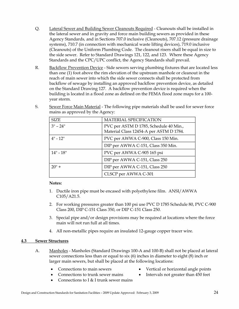
S. Sewer Force Main Material - The following pipe materials shall be used for sewer force mains as approved by the Agency:
SIZE MATERIAL SPECIFICATION 3" – 24" PVC per ASTM D 1785, Schedule 40 Min.,
Material Class 12454-A per ASTM D 1784. PVC per AWWA C-900, Class 150 Min. 4" - 12" DIP per AWWA C-151, Class 350 Min. PVC per AWWA C-905 165 psi 14" - 18" DIP per AWWA C-151, Class 250 DIP per AWWA C-151, Class 250 20" + CLSCP per AWWA C-301
Notes:
1. Ductile iron pipe must be encased with polyethylene film. ANSI/AWWA C105/A21.5.
2. For working pressures greater than 100 psi use PVC D 1785 Schedule 80, PVC C-900 Class 200, DIP C-151 Class 350, or DIP C-151 Class 250.
3. Special pipe and/or design provisions may be required at locations where the force main will not run full at all times.
4. All non-metallic pipes require an insulated 12-gauge copper tracer wire.
4.3 Sewer Structures
A. Manholes - Manholes (Standard Drawings 100-A and 100-B) shall not be placed at lateral sewer connections less than or equal to six (6) inches in diameter to eight (8) inch or larger main sewers, but shall be placed at the following locations:
• Connections to main sewers • Connections to trunk sewer mains • Connections to I & I trunk sewer mains
• Vertical or horizontal angle points • Intervals not greater than 450 feet
Design and Construction Standards for Sanitation Facilities – 2009 Update Approved: February 3, 2009 25
Where practical, manholes shall be located near the center of street intersections. All manholes from which future sewer line extensions are anticipated shall have a pipe stub planned and installed at the grade and the direction of the anticipated sewer extension (see Section 4.02 L) of these Agency Standards. The following regulations shall also apply:
1. A standard drop manhole (Standard Drawing 101, 60-inch) shall be installed when the invert elevation of the incoming sewer is greater than two (2) feet higher than the top of the outgoing sewer.
2. A drop manhole slide (Standard Drawing 103) shall be installed when the invert elevation of the incoming sewer is two (2) feet or less higher than the invert of the outgoing sewer.
3. The elevation difference between the inflow and outflow through the manhole shall be a minimum of 0.10 of a foot where there will be more than thirty (30) degrees deflection between any inlet line and the outlet line of a manhole.
4. The angle of deflection between incoming and outgoing lines in a manhole shall not be greater than ninety (90) degrees. If the angle of deflection is greater than 90°, two manholes shall be used.
5. All lines connecting to existing manholes shall conform to the Standard Drawings for new manholes (Standard Drawings 100-A and 100-B), unless otherwise approved by the Agency.
B. Main Sewer Cleanout - A Main Sewer cleanout (conforming to the requirements of Standard Drawings 105 or 106) shall be installed at the terminus of main sewers that will not be extended, if such terminal cleanout is located within 225 feet of the nearest downstream manhole.
C. Test Fittings - All test fittings shall, unless otherwise approved by the Agency, be tees or wye branches of the same size, type and quality as that of the line in which they are being installed. The branch of all test fittings shall be installed in an upright position.
D. Pressure Frame and Covers - When specified by the Agency, pressure (water-tight or gasketted and bolt down) frames and covers shall be installed where drainage conditions may cause storm or flood waters to inundate sewer structures.
E. Modification of Structures - All structures to be remodeled shall comply with the Standard Drawings. Remodeling of any structure shall be specified and/or detailed on the plans and approved by the Agency prior to any remodeling work.
F. Special Structures - Trunk sewer manholes, siphons, pumping stations, and other unusual structures require specific design approval by the Agency.
G. Private Main Sewer Connections – When allowed by the Agency, private main sewers for parks, mobile home parks, and other such permitted organizations, regardless of size of private main sewer, shall connect to the public main sewer at a manhole.
Design and Construction Standards for Sanitation Facilities – 2009 Update Approved: February 3, 2009 26
4.4 Accessibility
A. All sewer easements shall be provided with a 12-foot gate and, if locked, an Agency lock shall be inserted in series. Coordinate with Agency.
B. All easements and access road easements shall be a minimum of 15 feet wide unless otherwise approved by Agency.
C. Access roads shall be minimum 12 feet wide unless otherwise approved by Agency.
D. Access must be available 24 hours per day, year.
4.5 Public Pump Stations
A. General Requirements
1. Public pump stations will not be allowed where an alternative gravity route exists. 2. Public pump stations shall be designed to serve the entire tributary flow at build-out
densities conforming to the current Sonoma County General Plan under peak hour and 24-hour flow rates.
3. Public pump stations must be wet-well type, equipped with submersible pumps with quick couplings. The pumps shall be rail mounted and fitted with chains for removal of the pumps.
4. Public pump stations are not allowed within street rights-of-way. 5. A paved access road to allow service vehicles to be parked off the street and clear of
the sidewalks. Turnarounds may be required for stations constructed along heavily traveled streets. Service vehicle access to wet-well.
6. A reinforced concrete base slab sized adequately to counteract buoyancy. Provide supporting design calculations and details.
7. A single-surface pad over wet-well, the area supporting the generator and fuel supply tanks.
8. The wet-well shall be a minimum sixty (60) inches in diameter, and shall include a resilient seat gate valve on the line into wet-well.
9. A 6-inch PVC emergency bypass system consisting of a suction line and a discharge line equipped with cam-lock connectors. Bypass suction line shall extend to eight (8) inches above floor of wet-well and to eighteen (18) inches above finished grade at surface. Discharge line connects to force main through a full port ball valve and a check valve. Provide locking caps for both suction and discharge connectors. Adequately support all pipes.
10. A water service with reduced pressure backflow preventer where water service is available.
11. Calculations to determine the need for hydrogen sulfide suppression in force main. 12. Public pump stations shall also be designed and constructed in accordance with
pertinent portions of Section 710.0 inclusive (Drainage of Fixtures Located Below the Next Upstream Manhole or Below the Main Sewer Level) of the UPC/CPC.
B. Pumping Equipment
1. All pumps, motors, internal valves and piping, level indicators, control switches, ladders, and alarms shall be manufactured and assembled as a package. Supply and warranty shall be through one company.

Design and Construction Standards for Sanitation Facilities – 2009 Update Approved: February 3, 2009 27
2. The pumps shall be submersible, self-priming, vertical, centrifugal sewage pumps. Pumps shall be capable of passing a maximum solid, 2½-inch diameter sphere.
3. Two matched pumps and controls to alternate lead and lag pump. 4. A spare duplicate pump shall be provided to Agency. 5. Provide an elapsed time meter for each pump.
C. Electrical Equipment
1. Provide freestanding electrical service, and transfer panel in a heavy duty NEMA 3-R Dead Face Control weatherproof box at least 48 inches above the ground. Provide 110-volt duplex GFI receptacles and light inside. All boxes shall be of corrosion resistant construction.
2. Provide receptacle connector for mobile generator. Size and type of connection shall be as approved by the Agency.
3. Provide OSHA-approved rubber mat in front of all control panels. 4. Provide ability to operate station with one pump removed for maintenance. 5. Provide hand-off-automatic (HOA) switch to operate pumps for testing.
D. Telemetry
1. Provide a standard telephone service capable of handling multiple alarms such as high/low, wet-well, flow, pressure, and intrusion.
E. Details Required On Improvement Plans
1. Site Plan: Locations of power pole, transfer switch, control panel, wet-well, ground slab, driveway, fencing, water service, emergency suction/discharge connections, and emergency electrical shut-off.
2. Wet-well: Influent piping (standard inside drop manhole); emergency suction line; bubbler line including connection hardware; water/alarm levels (pump on, pump off, low level, high level), redundant high water float switch.
3. Emergency Power: Emergency power shall be either mobile or stationary as determined by the Agency. Electrical details specified to include size and material of conduit, switch gear, telemetry compatibility. Electrical details shall include power source, meter location, cabinetry, and grounding. Wiring diagrams shall depict connection to and between PG&E, transfer switch, and emergency generator. A residential muffler shall be provided. A stationary emergency power unit/fuel tank shall be housed in a code-approved, block-constructed building.
4. Public Force Main Discharge Manhole: Inverts, channelization, and detail of the force main connection.
5. Landscaping Plan: Provide a landscape and irrigation plan for approval by the Agency.
4.6 Private Individual Pump Stations
A. General Requirements
1. Private individual pump stations shall not be allowed where an alternative gravity route exists.
Design and Construction Standards for Sanitation Facilities – 2009 Update Approved: February 3, 2009 28
2. Private individual pump stations shall be wet-well type, equipped with submersible pump(s) with quick coupling(s). The pump(s) shall be rail mounted and fitted with stainless steel chain(s) for removal of the pump(s).
3. Private individual pump stations are not allowed within street rights-of-way. 4. Service vehicle access to wet-well shall be provided. 5. A reinforced concrete base slab sized adequately to counteract buoyancy shall be
provided with supporting design calculations and details. 6. A water service with a supported aboveground hose bibb and reduced pressure
backflow preventer shall be provided where water service is available. 7. Calculations to determine the need for hydrogen sulfide suppression in the force
main shall be provided. 8. Private individual pump stations shall be designed and constructed in accordance
with pertinent portions of Section 710.0 inclusive (Drainage of Fixtures Located Below the Next Upstream Manhole or Below the Main Sewer Level) of the UPC/CPC, and Standard Drawing 129.
9. Submit design documents to the Agency for review and approval.
B. Pumping Equipment
1. All pumps, motors, internal valves and piping, level indicators, control switches, ladders, and alarms shall be manufactured and assembled as a package. Supply and warranty shall be through one company.
2. The pumps shall be submersible, self-priming, vertical, centrifugal sewage pumps. Pumps shall be capable of passing a maximum 2-inch diameter solid sphere.
3. Private individual pump stations shall be either a simplex (single pump) or duplex (two pumps) configuration.
4. Provide an elapsed time meter for each pump.
C. Electrical Equipment
1. Provide freestanding electrical service and UL Listed simplex or duplex control panel with NEMA 4X enclosure at least 48 inches above the ground. Use intrinsically safe relays for hazardous environments. Provide 110-volt duplex GFI receptacles and light inside. All boxes shall be of corrosion resistant construction.
2. Provide float switch for visual and audible high-water alarm. 3. Provide OSHA-approved rubber mat in front of all control panels. 4. Provide hand-off-automatic (HOA) switch to operate pumps for testing.
D. Details Required on Improvement Plans
1. Site Plan: Locations of power pole, control panel, wet-well, ground slab, driveway, fencing, water service, emergency suction/discharge connections, and emergency electrical shut-off.
2. Wet-well: water/alarm levels float switches (pump on, pump off, low water level, high water level, and redundant high water level).
3. Private Force Main Discharge Lateral Connect: Detail of the private force main discharge connection to public sewer system.

Design and Construction Standards for Sanitation Facilities – 2009 Update Approved: February 3, 2009 29
SECTION 5 - PLAN APPROVAL AND PERMIT ISSUANCE
5.1 General
The procedure outlined in this section shall be followed for submittal, review, and approval of plans and permit issuance for sewer main extensions.
5.2 Plan Checking Fee
The plan-checking fee shall be paid to PRMD prior to any review of plans. This fee is not refundable. However, upon issuance of a sewer construction permit, any unused portion of the plan checking fee will be credited against the total plan checking and inspection fees due under the Sanitation Code.
5.3 Preliminary Review
To facilitate the processing and review of plans, all of the following materials shall be submitted at least forty (40) days (PRMD to set this time limit) prior to the time at which approval of plans is desired. If plans require revisions, additional review time will be required.
A. Two (2) 24" X 36", blue line or black line, complete sets of drawings, including sewer plans and profiles and finish grading plans.
B. If a Survey of Commercial/Industrial Wastewater Discharge Requirements (Survey) is required by the Agency, a third set of drawings, a copy of the building plumbing plans, and a copy of the Survey are required (all commercial and industrial projects).
C. One (1) set of potholing data for utilities that may conflict with the proposed sewer design.
D. Two (2) complete sets of any required special specifications/provisions.
E. Two (2) copies of the Project Engineer's preliminary cost estimates, signed and stamped by the Project Engineer.
F. Two (2) complete sets of any required public sewer easement documents required by Section 3.4 (Sanitary Sewer Easements).
G. If the project is a subdivision, one (1) complete copy of the final map or parcel map.
H. Two (2) copies of calculations for system sizing stamped and signed by the Design Engineer.
I. Two (2) copies of all other engineering, geotechnical, or other technical reports related to the project.
After submittal, the above materials will be reviewed by PRMD. If there are any required corrections and/or recommended revisions, they will be noted on the plans, easements, etc., and one set will be returned to the Project Engineer for revisions and resubmittal. This procedure will be repeated until all Agency requirements are met and the plans and any required public sewer easements are ready for approval by the Agency.

Design and Construction Standards for Sanitation Facilities – 2009 Update Approved: February 3, 2009 30
5.4 Final Review and Approval
In order to obtain final approval, the Project Engineer shall submit the following materials, as revised in accordance with the above Section 5.3.
A. Two (2) complete sets of sewer drawings, including plans and profiles: One (1) mylar or electronic plot on vellum) and one (1) set of blueline or black line prints.
B. One (1) complete set of any required special specifications.
C. One (1) copy of maps and descriptions for any required easements (one (1) copy for each grantor involved).
D. Any other pertinent plans, information or materials specifically required by the Agency. When all of these materials are received and given final review, the plans shall be stamped and signed by the Project Engineering and submitted to the Agency for approval. After approval of the plans, all copies will be signed by the Agency. The Agency will then retain one set of plans and return all other sets of plans to PRMD for distribution.
5.5 Changed Conditions
In the event that any plan or field condition is encountered during construction that necessitates deviation from the approved plans, all work affected by the deviation shall be halted. The first solution will be to make a field change. If this is not possible, then the plans shall be revised by the Project Engineer and resubmitted to the Agency for approval by the Agency. When revisions are required, the Project Engineer shall submit two (2) preliminary copies of the proposed revised sheets of the plans along with a letter explaining the recommended revisions and why they are required. When the revisions are in approvable form, submit four (4) copies of plans and two (2) sets of blue line or black line prints all stamped and signed by the Project Engineer for signature by the Agency, with the same distribution as that for the original plans. The Project Engineer shall be responsible for ensuring that all revisions are appropriately shown on the record drawings for the project. In addition, the Project Engineer shall make corrections to improvement plans when errors or omissions are discovered following approval of the plans by the Agency.
5.6 Statement of Fees and Charges
During Agency review of the plans but prior to final approval, an estimate of fees and charges, will be sent to the Owner, detailing the fees and charges which must be paid prior to issuance of the sewer connection permit.
5.7 Issuance of the Permit
A. A sewer construction permit will be granted only after all Agency requirements have been met including: 1. final approval of plans and specifications 2. payment of all appropriate fees and charges 3. posting of the required performance, maintenance, and payment bond amounts 4. acquisition of all required easements 5. completion of wastewater discharge survey 6. compliance with all pre-treatment requirements

Design and Construction Standards for Sanitation Facilities – 2009 Update Approved: February 3, 2009 31
7. completion of all relevant project conditions 8. filing of a permit application form
B. No work shall be permitted to proceed until the permit has been issued.
5.8 Subdivisions
Before approving the recordation of a subdivision map, the City of Sonoma, the City of Santa Rosa, and/or PRMD will require a letter or notification from the Agency stating that plans and specifications for necessary sewerage facilities to serve each lot in the subdivision have been approved by the Agency.
5.9 Items to Consider Before Submitting Plans
The following is a general list of items that should be considered by the Project Engineer before submitting plans for review and approval by the Agency.
A. Is the property to be sewered within an Agency Sanitation Zone or a District?
B. If the property is not in an Agency Sanitation Zone or a District, has the Owner requested in writing from the Agency or District, and LAFCO, that the property be annexed and submitted the required fees to PRMD and LAFCO?
C. Have arrangements been made for the payment of the plan checking fee to PRMD?
D. Are there any special details needed, such as special drawings, notes, and/or specifications to supplement the Standard Specifications?
E. Can the proposed sewerage system provide service to properties other than those properties for which the sewer is to be installed? If so, have full provisions been made for the additional service or future extension?
F. Has approval been secured from the County, the Agency, or the City having jurisdiction for any sewer line crossings of storm water channels?
G. Are all necessary easements prepared, accepted, and recorded?
H. Are special permits and/or licenses required in connection with the work?
SECTION 6 - CONSTRUCTION ENGINEERING
6.1 General
All construction work and support work for construction shall be in accordance with the applicable sections of the Standard Specifications, as modified below.
6.2 Staking Requirements
The Project Engineer shall be responsible for providing all necessary field surveys and construction staking. Grade and alignment stakes shall be set in advance of any trenching or excavation and, in general, stakes for straight sewers shall be set at 25 to 50-foot intervals, depending upon topography. Intervals of 25 feet or less shall be used through all horizontal and vertical curves. Stakes shall be appropriately marked to show the station, the offset, and the cut to sewer invert.

Design and Construction Standards for Sanitation Facilities – 2009 Update Approved: February 3, 2009 32
6.3 Side Sewer Location
Prior to installation of lateral sewers, the lateral location and elevation at the property line shall be staked and flagged in the field by the Project Engineer.
6.4 Survey Authorization and Responsibility
When a survey is to be made on private property for a public sewer, obtain permission of the property owner prior to entry. The Agency, the Districts, and the County, will not be answerable or accountable in any manner for any loss or damage that may occur during or as a result of survey work by others.
6.5 Record Drawings
Upon completion of the work and prior to acceptance by the Agency, the Project Engineer shall provide record drawings to the Agency. Record drawings shall consist of all details shown on the original approved plans, corrected and/or expanded to reflect all design or construction changes from the approved plans. Particular attention shall be paid to changes in the following items: A. Sewer line and structure locations B. Surface and invert elevations of structures C. Slope, size, type of pipe, and length between structures D. Wye and lateral locations (Total distance from the downstream manhole to the wye,
plus the length of the lateral)
The Project Engineer shall submit a preliminary copy of the record drawings for review by PRMD. After review and approval by the inspector and the PRMD Sanitation Section staff or other Agency representative, the Project Engineer shall submit one (1) electronic media DWG, DXF, or TIF format file compatible with a currently supported the current version of AutoCAD approved by the Agency, noted and signed by the Project Engineer as "Record Drawings" (see Section 3-02).
SECTION 7 - PERMITS, LICENSES, AND BONDS
Section 7 covers all work that is performed as an Agency project including, but not limited to, land development. Permits from other jurisdictions may be required.
7.1 Permits
A. Sewer: All work performed in relation to and for connection to an Agency or District sewer system requires a specific permit in accordance with the current Agency's and appropriate District's Sanitation Code.
1. Main Sewer, Structure, and Manhole Installation Permits - Engineered plans are required in accordance with Sections 1 through 6 of these Agency Standards.
2. Lateral Sewer, and Building Sewer Connection Permits - Location plans are required when a 6-inch or larger lateral sewer is to be installed and at any other time when specifically required by the Agency.

Design and Construction Standards for Sanitation Facilities – 2009 Update Approved: February 3, 2009 33
B. OSHA Permit: If the work requires an OSHA permit, the permit shall be kept at the job site and a copy provided to the Agency.
C. Encroachment Permit: A public road/street dedicated and accepted by the State of California, County, or City allows for the Agency or District to excavate, install, repair, replace, remove, re-construct, operate, maintain and use a public sewer facility in the location designated by the Project Engineer with a permit from said state, County, or City.
7.2 Licenses
Contractors performing work requiring permits by the Agency shall be licensed with a Class A General Engineering Contractor License or C-34 for underground projects. Work on public property, streets, roads, and other public rights-of-way shall only be performed by duly licensed contractors. Property owners may perform building sewer work on their own property.
7.3 Bonds
Prior to the issuance of a permit for a sewer main extension (public sewer construction), the applicant shall furnish the Agency a faithful performance bond, cash, or other securities acceptable to the Agency in the amount of the total estimated cost of the work, whichever is greater. Such faithful performance bond, cash deposit, or other improvement security shall be conditioned upon the performance of the work in accordance with the terms and conditions of the permit and, unless more stringent requirements are otherwise specified by the Agency, shall warrant the correction of faulty workmanship and the replacement of defective materials for a period of one (1) year from and after the date of acceptance (filing of the Notice of Completion) of the work by the Board of Directors. A separate bond will not be required when the County or the City of jurisdiction holds an equivalent security.
SECTION 8 - CONTROL OF WORK
8.1 Reference Standards and Specifications
This Section of the Agency Standards covers both general and technical requirements for construction of sanitation facilities. Working titles having a masculine gender, such as "workmen" and journeyman" and the pronoun "he," are utilized in the Standard Specifications and these Agency Standards for the sake of brevity, and are intended to refer to persons of either sex. All work, unless otherwise indicated on the project drawings, shall be accomplished in accordance with the Standard Specifications or these Agency Standards, whichever is more stringent.

Design and Construction Standards for Sanitation Facilities – 2009 Update Approved: February 3, 2009 34
Where references are made to specifications other than the Standard Specifications for portions of the work, such references shall apply only to construction methods and materials used in said portions. Any reference to measurement and payment or to extra work provisions in such referenced specifications shall not apply, unless otherwise specifically stated in these Agency Standards or the Standard Specifications.
8.2 Conformity with Plans and Allowable Deviations
Finished surfaces shall conform to the lines, grades, cross-sections, and dimensions shown on the approved plans. Deviations from the approved plans and working drawings, as may be required by the exigencies of construction, will be determined by the Agency and authorized in writing.
8.3 Alternative Drawings
Alternative drawings will be allowed on a case-by-case approval of the Agency.
8.4 Survey Work by Project Engineer
Where survey for this work is done by the Project Engineer or his designated representative or subcontractor, a copy of various survey notes, such as cut sheets and line surveys, shall be provided to the Agency prior to the start of work. If any part of the survey work is compiled by electronic methods, the Project Engineer shall provide coordinate points and any data to the Agency in digital form in a DWG, DXF, or TIF format compatible with a currently supported version of AutoCAD approved by the Agency. A control diagram over a topographic base shall be provided showing the arrangement of existing basin control, horizontal and vertical; recovered and utilized for origin and closure, the arrangement of monumented control network; a table of adjusted coordinates; elevations and descriptions for all stations; graphic scales; grid ticks at 10-inch spacings and north arrow; and swing-tie sketches for local recovery of traverse stations. The control diagram shall be drawn on 4-mil Mylar, 24-inch x 36-inch in size.
8.5 Tests by Project Engineer
When various tests are performed in connection with the work, such as concrete, compaction, and other material tests, a copy of the test results shall be provided to the Agency within 72 hours of their becoming available.
8.6 Salvage of Existing Materials
Unless otherwise permitted by the Agency, all old castings for manholes, cleanouts, and any other salvage construction materials that have been a part of the Agency's or District's sewerage system may be claimed by the Agency. If the Agency or District claims such materials, they shall be stockpiled at a designated location at the job site. Agency or District forces will remove such salvaged materials.

Design and Construction Standards for Sanitation Facilities – 2009 Update Approved: February 3, 2009 35
8.7 Crossing Under Railroad, Highway, or Utilities
When any railroad, highway, or private or public utility is crossed, comply with all precautionary construction measures required by the owner of the railroad, highway, or utility. Unless otherwise specified, the Contractor shall obtain and pay for all necessary permits, licenses, bonds, and fees required for the crossing and give all notices necessary and incident to the work.
8.8 Pressure Testing of Gravity Sewer Pipes
Testing of all sewer pipes, including main sewers, trunk sewer mains, I & I trunk sewer mains, side sewers, and all other sewer pipes outside of buildings that connect to the public sewers, shall be tested in accordance with the following: A. Water Testing
1. For either exfiltration or infiltration test, the maximum leakage shall not exceed 50 gallons per inch of pipe diameter per mile per 24 hours as measured over a period of 30 minutes minimum. Refer to Standard Drawing 115. Should the leakage exceed the maximum allowable rate, the Contractor shall repair, overhaul, or rebuild the defective portion of the sewer line such that the allowable leakage requirement listed above is met.
2. Generally, all testing shall be done after all trenches are compacted, roadway subgrade and base rock compaction is completed, and the curb/gutters have been installed.
3. In the event that the exfiltration test prescribed above is impractical due to wet trench conditions, those portions of the sewer line where such conditions are encountered will be tested for infiltration using the method described in Section 306-1.4.3 of the Standard Specifications. The Agency shall determine whether the exfiltration or infiltration test will be used.
4. The Contractor shall repair any obvious leaks, even if the test for leakage is within the prescribed limits.
B. Air Testing - Low pressure air testing may be used in lieu of water testing at the option
of the Contractor. The following procedure shall be used for air testing.
1. Prior to testing, clean pipe to be tested by propelling a snug fitting inflated rubber ball through the pipe with water and remove any debris.
2. Plug all pipe outlets with suitable test plugs. Brace each plug securely.
3. If the pipe to be tested is submerged in groundwater, insert a pipe probe by boring or jetting into the backfill material adjacent to the center of the pipe, and determine the pressure in the probe when air passes slowly through it. This is the backpressure due to groundwater submergence over the end of the probe. All gauge pressures in the test shall be increased by this amount.
4. Add air slowly to the portion of the pipe being tested until the internal pressure is raised to 4.0 psig

Design and Construction Standards for Sanitation Facilities – 2009 Update Approved: February 3, 2009 36
5. Check exposed pipe and plugs for abnormal leakage by coating with a soap solution. If any leakage is observed, bleed off air and make necessary repairs.
6. After an internal pressure of 4.0 psig is obtained, allow at least two (2) minutes for air temperature to stabilize, adding only the amount of air required to maintain pressure.
7. After the two (2) minute period, disconnect the air supply.
8. When pressure decreases to 3.5 psig, start stopwatch. Determine the time in seconds that is required for the internal air pressure to reach 2.5 psig. The minimum allowable time in seconds shall be based on the diameters and lengths of pipe under test. Refer to Standard Drawing 116.
8.9 Television Inspection
A. Inspection: The Contractor shall perform a closed-circuit television inspection of all newly constructed sewers including main sewers and lateral sewers and all new lateral sewers connected to existing main sewers. Videotape in color VHS format or digital media format of the television inspection along with a written report (log) and a legible copy of the Contractor's working drawings, shall be produced and delivered to the Agency. The video inspection and report log for main sewers (voice or data display) shall include the reach; locations of stop/start; deficiencies, laterals, and length of reach; time; date; and name of operator. The video inspection and report log for lateral sewers (voice or data display) shall include main sewer station of lateral, street address served by lateral, locations of stop/start, deficiencies, length of lateral, time, date, and name of operator. Closed-circuit television inspection shall be part of the cost of construction. The Agency will review the videotape or digital media video inspection and report log, and will notify the Contractor verbally and in writing within 10 working days of receipt of video of any deficiencies that will require repair. Following notification the Contractor shall excavate and make the necessary repairs and perform a television re-inspection complete with report log which shall be re-submitted to the Agency for review. The following conditions shall exist prior to the television inspection:
1. All sewer lines shall be in installed, backfilled, and compacted.
2. All structures shall be in place, all channeling complete, and all pipelines accessible from structures.
3. All other underground facilities, utility piping, and conduit within two (2) feet of the sewer main shall be installed.
4. Pipelines to be inspected shall be balled, flushed, and shall be mandrel tested in accordance with the procedures in Section 306-1.2.12 of the Standard Specifications.
5. The final air or water test shall have been completed.
6. Immediately before the television inspection, fresh water shall be run into the sewer until it passes through the downstream manhole.
When the above work has been completed, the Contractor shall notify the Agency 2 working days in advance of the date for television inspection.
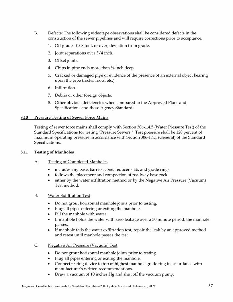
Design and Construction Standards for Sanitation Facilities – 2009 Update Approved: February 3, 2009 37
B. Defects: The following videotape observations shall be considered defects in the
construction of the sewer pipelines and will require corrections prior to acceptance.
1. Off grade - 0.08 foot, or over, deviation from grade.
2. Joint separations over 3/4 inch.
3. Offset joints.
4. Chips in pipe ends more than ¼-inch deep.
5. Cracked or damaged pipe or evidence of the presence of an external object bearing upon the pipe (rocks, roots, etc.).
6. Infiltration.
7. Debris or other foreign objects.
8. Other obvious deficiencies when compared to the Approved Plans and Specifications and these Agency Standards.
8.10 Pressure Testing of Sewer Force Mains
Testing of sewer force mains shall comply with Section 306-1.4.5 (Water Pressure Test) of the Standard Specifications for testing "Pressure Sewers." Test pressure shall be 120 percent of maximum operating pressure in accordance with Section 306-1.4.1 (General) of the Standard Specifications.
8.11 Testing of Manholes
A. Testing of Completed Manholes
• includes any base, barrels, cone, reducer slab, and grade rings • follows the placement and compaction of roadway base rock • either by the water exfiltration method or by the Negative Air Pressure (Vacuum)
Test method.
B. Water Exfiltration Test
• Do not grout horizontal manhole joints prior to testing. • Plug all pipes entering or exiting the manhole. • Fill the manhole with water. • If manhole holds the water with zero leakage over a 30 minute period, the manhole
passes. • If manhole fails the water exfiltration test, repair the leak by an approved method
and retest until manhole passes the test.
C. Negative Air Pressure (Vacuum) Test
• Do not grout horizontal manhole joints prior to testing. • Plug all pipes entering or exiting the manhole. • Connect testing device to top of highest manhole grade ring in accordance with
manufacturer's written recommendations. • Draw a vacuum of 10 inches Hg and shut off the vacuum pump.

Design and Construction Standards for Sanitation Facilities – 2009 Update Approved: February 3, 2009 38
• Measure length of time to drop to 9 inches Hg. • If time is greater than the time shown in the following table, the manhole passes the
vacuum test.
Manhole Diameter (inches) 60 72
Manhole Depth (feet)
Time (Seconds) Time (Seconds) < 4 10 13 16 6 15 20 25 8 20 26 33 10 25 33 41 12 30 39 49 14 35 46 57 16 40 52 67 18 45 59 73 20 50 65 81 22 55 72 89 24 59 78 97 26 64 85 105 28 69 91 113 30 74 96 121
• Adjust vacuum if necessary due to external hydrostatic pressure (proceed with test
only upon Agency's approval).
• If manhole fails the vacuum test, repair the leak by an approved method and retest until manhole passes the test.
If the testing indicates no leakage or a passed vacuum test, but weeping of groundwater is observed at the joints, said joints shall be repaired by an approved method to eliminate the leakage.
SECTION 9 – APPROVED MATERIALS LIST
9.1 Substitute Material Approval Process
Other manufacturers' products may be approved for use upon submission of product information and samples (non-returnable) for review/testing purposes. Other products will be reviewed/tested for conformance with recognized standards, such as AWWA and ASTM, and for a performance history. If a submitted product is approved, the Agency shall approve such products as an "Approved Equal" for use.
9.2 Approved Materials and Manufacturers
A. Standard Drawings 100 (A, B, C), 101, 103, 109, 110, 121
1. Bolted Couplings conforming to AWWA C-219: a. Wrap all couplings with minimum of two layers of coal tar-based tape.

Design and Construction Standards for Sanitation Facilities – 2009 Update Approved: February 3, 2009 39
b. Acceptable manufacturers:
APAC 300 Series Dresser 3501 Series Powerseal 441 Series Rockwell 501 Series Romac 441 Series Smith-Blair Style 253 Or Approved Equal
B. Standard Drawings 100 (A, B, C), 101, 103, 117-B, 118 (A, B), 119, 120 (A, B, C1, E), 134
1. Waterstops for Cast-in-Place Structures and for Cast-in-Place Structure connections: a. Use PVC or rubber waterstops approved by the pipe manufacturer. b. Use double or two single waterstops unless noted otherwise. c. Acceptable manufacturers:
Fernco EJP Or Approved Equal
C. Standard Drawings 100 (A, B, C), 102, 103, 120 (A, B)
1. Plastic gasket: a. Acceptable manufacturers:
Ram-Nek by K.T. Snyder Company Kent Seal No. 2 by Hamilton Kent Manufacturing Company Or Approved Equal
D. Standard Drawings 100 (A, B, C), 101, 102, 103, 117, 118 (A, B), 119 (A, B), 120 (A, B, C)
1. Coatings: a. Acceptable manufacturers:
Tegra Seal Thoroseal Zypex Or Approved Equal
E. Standard Drawings 100 (A, B, C), 101, 103, 120 (A, B, C)
1. Precast manhole base: a. A-Lok connectors and other components, unless noted otherwise on Standard
Drawings. b. Acceptable manufacturers:
Jensen Precast Central Pre-Cast Products Or Approved Equal

Design and Construction Standards for Sanitation Facilities – 2009 Update Approved: February 3, 2009 40
F. Standard Drawing 104
1. Manhole frame and cover: a. Marked SEWER b. Acceptable manufacturers:
Manufacturer Normal Application (Non-Gasketted Versions)
Flood-Prone Area Application (Gasketted Versions)
D&L Supply A-1024CPH E-1928CPH
South Bay Foundry SBF-1900CPH SBF – 1900CPH/BS
Phoenix Iron Works P-1090 R/G P-1002
Certainteed PAMREX with SCS Locking Kit with Handled Key (C15)
PAMTIGHT
Or Approved Equal G. Standard Drawings 105, 121, 124
1. Cleanout rim and cover: a. Vertical b. Marked SEWER c. Use cast iron lids/traffic rated box for traffic areas d. Acceptable manufacturers:
1) 4-Inch Sewer Cleanouts:
D&L Supply M8030 with lid marked "SEWER" Geneco CCR with lid marked "SEWER" South Bay Boundary B5230 with lid marked "SEWER" Or Approved Equal
2) 6" and 8" Sewer Cleanouts
Christy G-5 D&L H-8028 CPH or H-8030 CPH South Bay Foundry SBF 1246-S CPH Phoenix Iron Works P-2501 CPH Or Approved Equal
H. Standard Drawing 106
1. Oblong Cleanout rim and cover: a. Marked SEWER b. Acceptable manufacturers:
D&L H6530 for 6", H6531 for 8" South Bay Foundry SBF-1247 for 6", SBF-1249 for 8" Phoenix Iron Works P-7002 for 6", P-7004 for 8" Or Approved Equal

Design and Construction Standards for Sanitation Facilities – 2009 Update Approved: February 3, 2009 41
2. Round Cleanout rim and cover: a. Marked SEWER. b. Acceptable manufacturers:
D&L H-8026 CPH South Bay Foundry SBF-1257 CPH Phoenix Iron Works P-7001 CPH Or Approved Equal
3. No. 15 Asphalt Felt conforming to ASTM D226 I. Standard Drawings 105, 106, 121, 124, 130, 132
1. Plastic Mechanical Plug: a. Acceptable manufacturers:
Cherne "Gripper" End-of-Pipe plug style Lansas "Posi-Seal" End-of-Pipe plug style Plum Best "Plum-Tite" ETCO "T" Cone (Countersunk) Jones Stephens Corp. "T" Cone (Countersunk) Or Approved Equal
J. Standard Drawing 131
1. Plastic Threaded Plug: a. Acceptable manufacturers:
ETCO "T" Cone (Countersunk) Jones Stephens Corporation "T" Cone (Countersunk) Or Approved Equal
K. Standard Drawing 107
1. Geotextile Filter Fabric: a. Acceptable manufacturers:
Mirafi 140 NC nonwoven geotextile Synthetic Industries 401 nonwoven geotextile Or Approved Equal
L. Standard Drawings 109, 110, 111
1. Polyethylene Film: a. Tube form b. Conforming to AWWA/ANSI C-105/A21.5
M. Standard Drawing 111
1. Pre-cast Valve box: a. Marked SEWER.

Design and Construction Standards for Sanitation Facilities – 2009 Update Approved: February 3, 2009 42
b. Acceptable manufacturers:
Christy G-5 Brooks 3-RT BES G-5 Or Approved Equal
2. Gate Valve:
a. Resilient wedge with smooth bore b. 2" through 12" c. AWWA C-509 d. Acceptable manufacturers:
American Flow Control Clow M&H Mueller Or Approved Equal
N. Standard Drawing 117-A
1. Pre-manufactured single stage grease interceptor tanks and hatches: a. Corrosion-resistant coated fabricated steel or b. Polyethylene, or c. Fiberglass d. In accordance with IAPMO Standards e. Acceptable manufacturers:
Zurn Plumbing Products Highland Tank & Manufacturing Company Or Approved Equal
O. Standard Drawings 117-B, 118- (A, B)
1. Precast concrete sand and grease interceptors: a. Tanks: Furnished in one piece b. Battery situation: Use several concrete tanks in series c. Concrete tanks: Constructed in accordance with IAPMO Standard PS 80
"Material and Property Standard for Grease Interceptors and Clarifiers" d. Acceptable manufacturers:
Jensen Precast M.C. Nottingham Co., Inc. Selvage Concrete Products Or Approved Equal

Design and Construction Standards for Sanitation Facilities – 2009 Update Approved: February 3, 2009 43
P. Standard Drawings 119, 120- (A, B, C1, C2)
1. Square Sampling box. a. Acceptable manufacturers:
Jensen Precast (36" x 36" only) Central Precast Products Model CP 3030 Or Approved Equal
2. Round Sampling Box: a. 30" Dia. RCP b. "B" Wall conforming to ASTM C76
3. Precast Concrete Manhole Components: a. Acceptable manufacturers:
Jensen Precast Central Precast Products Or Approved Equal
4. Sampler: a. Shall have, at a minimum, the following features:
1) Refrigerated 2) Weather and corrosion resistant 3) Able to collect composite or sequential sampling 4) Have an operating range of −20° to 120°F (−29° to 49°C) – without additional
heaters 5) 4-20mA flow meter input 6) Ability to perform:
a) Uniform time intervals – uniform sample volumes b) Uniform time intervals – flow-proportioned sample volumes c) Uniform sample volumes – flow-proportioned time intervals
7) A maximum suction lift of 28 ft (8.5m) 8) Automatic rinsing of suction line –up to 3 rinses for each sample collection 9) For composite samples; shall be programmable to collect from 1 to 999
samples 10) Sampling Frequency Specifications:
a) 1 minute to 99 hours 59 minutes, in 1-minute increments b) 1-9,999 flow pluses
Q. Standard Drawings 121, 122, 123, 124, 127, 128, 130, 131
1. Flexible Rubber Couplings for cut-in wye and other applications: a. 316 Stainless Steel Bands and Shear Ring. b. Acceptable manufacturers:
Fernco Indiana Seal Mission Rubber Caulder Clay Or Approved Equal

Design and Construction Standards for Sanitation Facilities – 2009 Update Approved: February 3, 2009 44
R. Standard Drawing 121
1. Tap process: a. Use "Tap-Tite" process b. Or Approved Equal
2. Strap-on Wye: a. Cast iron saddle for 10" and larger b. Acceptable manufacturers:
Geneco Sealtite E series with 304 Stainless Steel bands and connecting hardware Romac CB sewer saddle with 316 Stainless Steel bands and connecting hardware Or Approved Equal
S. Standard Drawings 100-C, 111, 120-C2, 121
1. Tracer Wire: a. No. 12 AWG Solid Copper Wire with THHN Insulation with 2" to 3" pigtail each
end as necessary b. Tape wire to pipe on 5 feet centers maximum using a tape that is suitable for
direct burial.
2. Vinyl adhesive tape: a. Minimum 1" wide b. Acceptable manufacturers:
3M Corporation - #471 5 mil thick minimum The 5S Store – 6 mil thick minimum Or Approved Equal
T. Standard Drawing 120-D2
1. Reduced Pressure Backflow Prevention Devices. a. IAPMO Listed b. AWWA C511 c. Designed in Accordance with State of California Title 17 d. Listed on the latest revision of the approved University of Southern California
Foundation for Cross-Connection Control and Hydraulic Research List 2. Mixing Valve: IAPMO and/or NSF Listed 3. Automatic Trap Primer: IAPMO and/or NSF Listed 4. Aboveground Pipe Thermal Insulation
a. Polyethylene extruded closed cell b. ½" minimum thickness c. Semi-slit construction d. Ultraviolet resistant and chemically inert e. Temperature range: -90 to +212 degrees F
5. Permanent Plastic Message Sign: a. Sign:
1) White 2) UV Resistant

Design and Construction Standards for Sanitation Facilities – 2009 Update Approved: February 3, 2009 45
3) Minimum Size: 18" wide x 12" tall x 3/16" thick 4) Solid polypropylene or solid polyethylene
b. Screws: 1) 3 each along top and 3 each along bottom 2) 316 Stainless Steel, ¼" Diameter x 1.5" long wood screw
c. Letters: 1) Black, All Capitals 2) UV Resistant 3) Minimum Height: ½" Tall
U. Standard Drawing 124
1. Foot Operated Drain Hole Cover for Recreational Vehicle Disposal Facility: a. Acceptable manufacturers:
4" OPW, 269 Sanitary Tank Hatch (269-0085) 4" Tower Company, Sanitary Hatch Cover (Part No. 05425) Or Approved Equal
V. Standard Drawings 125, 126
1. Cast Iron Clamp Style No-Hub Coupling a. Acceptable manufacturers:
MG Coupling Company, M-G Style coupling Or Approved Equal
W. Standard Drawings 126, 127
1. Backflow check valve: a. All metal construction. b. Acceptable manufacturers:
Jones Stephens Corp. B01-004 or B01-014 Zurn 1090, 1091, 1095 Or Approved Equal
2. Box - Non-traffic areas. a. Acceptable manufacturers:
Christy B-36 Or Approved Equal
3. Box - Traffic areas. a. Acceptable manufacturers:
Christy B-17"x30" Or Approved Equal

Design and Construction Standards for Sanitation Facilities – 2009 Update Approved: February 3, 2009 46
X. Standard Drawing 129
1. Private Individual Pumping Station Package. a. Acceptable manufacturers:
Zoeller Engineering Products Myers Hydromatic Ingersoll-Dresser ITT Flygt Grundfos Yeomans Chicago Pump Or Approved Equal
Y. Standard Drawings 130, 132
1. Private cleanout rim and cover: a. Marked SEWER b. Cast iron lids/traffic rated box for traffic areas: c. Non-traffic areas 1) Acceptable manufacturers:
Christy F8 Geneco CC4 Or Approved Equal
d. Traffic areas. 1) Acceptable manufacturers:
Christy G-5 Or Approved Equal
Z. Standard Drawing 137
1. Casing Insulator. a. Acceptable manufacturers:
PSI Calpico Or Approved Equal
2. End Seal. a. Acceptable manufacturers:
PSI Calpico Or Approved Equal
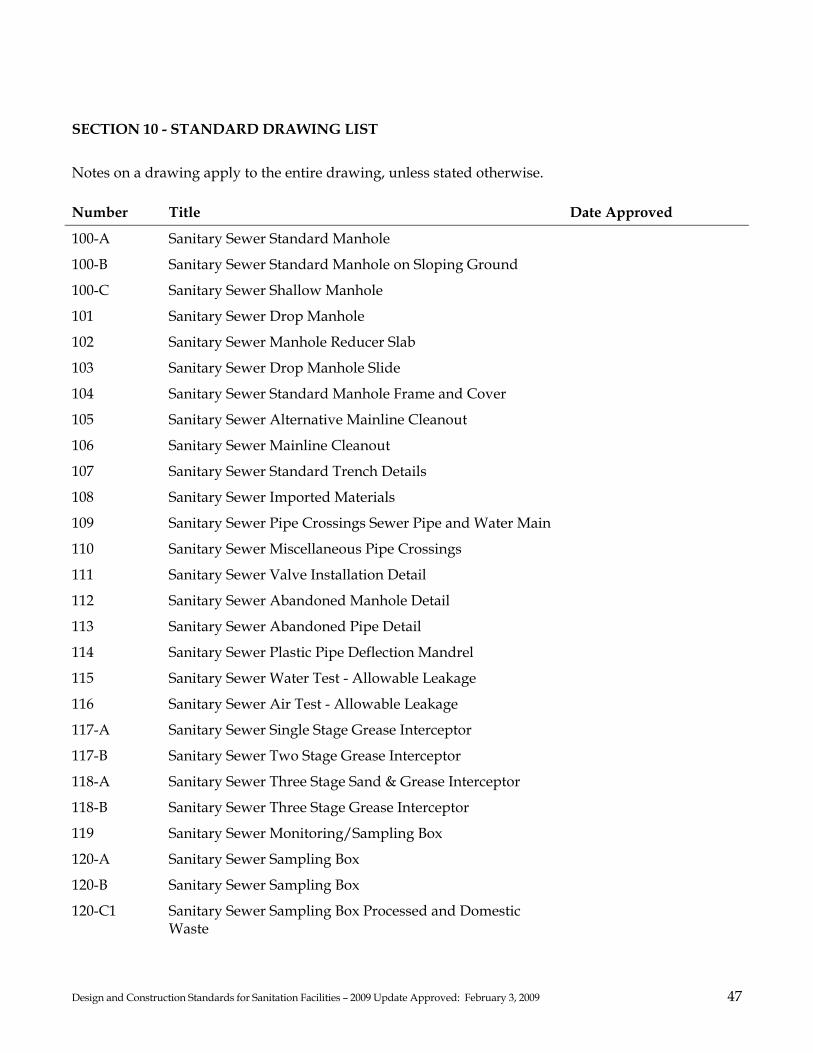
Design and Construction Standards for Sanitation Facilities – 2009 Update Approved: February 3, 2009 47
SECTION 10 - STANDARD DRAWING LIST
Notes on a drawing apply to the entire drawing, unless stated otherwise. Number Title Date Approved
100-A Sanitary Sewer Standard Manhole
100-B Sanitary Sewer Standard Manhole on Sloping Ground
100-C Sanitary Sewer Shallow Manhole
101 Sanitary Sewer Drop Manhole
102 Sanitary Sewer Manhole Reducer Slab
103 Sanitary Sewer Drop Manhole Slide
104 Sanitary Sewer Standard Manhole Frame and Cover
105 Sanitary Sewer Alternative Mainline Cleanout
106 Sanitary Sewer Mainline Cleanout
107 Sanitary Sewer Standard Trench Details
108 Sanitary Sewer Imported Materials
109 Sanitary Sewer Pipe Crossings Sewer Pipe and Water Main
110 Sanitary Sewer Miscellaneous Pipe Crossings
111 Sanitary Sewer Valve Installation Detail
112 Sanitary Sewer Abandoned Manhole Detail
113 Sanitary Sewer Abandoned Pipe Detail
114 Sanitary Sewer Plastic Pipe Deflection Mandrel
115 Sanitary Sewer Water Test - Allowable Leakage
116 Sanitary Sewer Air Test - Allowable Leakage
117-A Sanitary Sewer Single Stage Grease Interceptor
117-B Sanitary Sewer Two Stage Grease Interceptor
118-A Sanitary Sewer Three Stage Sand & Grease Interceptor
118-B Sanitary Sewer Three Stage Grease Interceptor
119 Sanitary Sewer Monitoring/Sampling Box
120-A Sanitary Sewer Sampling Box
120-B Sanitary Sewer Sampling Box
120-C1 Sanitary Sewer Sampling Box Processed and Domestic Waste

Design and Construction Standards for Sanitation Facilities – 2009 Update Approved: February 3, 2009 48
Number Title Date Approved
120-C2 Sanitary Sewer Four Pipe Sampling Box Processed and Domestic Waste
120-D1 Trash Enclosure
120-D2 Sanitary Sewer Trash Enclosure with Sewer Connection
120-E Sanitary Sewer Alternative Sampling Box
120-F Sanitary Sewer Sampling Box Building Notes
121 Sanitary Sewer 4 Inch and 6 Inch Service Lateral and Cleanout
122 Sanitary Sewer Typical Building Sewer Connection Details (For Connection to New Building)
123 Sanitary Sewer Building Cleanout Detail at Building (For Building Where Septic Tank is to be Abandoned)
124 Sanitary Sewer Recreational Vehicle Disposal Facility
125 Sanitary Sewer Mobile Home Connection
126 Sanitary Sewer Mobile Home Sewer Connection with Backflow
127 Sanitary Sewer Backflow Check Valve Installation Detail
128 Sanitary Sewer Discharge for Private Force Main
129 Sanitary Sewer Private Individual Pumping System Detail
130 Sanitary Sewer Building Cleanout Detail at Building
131 Sanitary Sewer Building Cleanout Detail at Building (Flood Plain Areas)
132 Sanitary Sewer Traffic Area Building Cleanout Detail
133 Sanitary Sewer Building Sewer Trench Detail
134 Sanitary Sewer Trench Dams
135 Sanitary Sewer Redwood Check Dam
136 Sanitary Sewer Above Ground Building Sewer
137 Sanitary Sewer Typical Casing Detail
138 Sanitary Sewer Sanitary Area Flow Characteristics

DRAWINGNUMBER:
SCALE: NONE
REVIEWED BY: APPROVED:02/03/09
DATE: 100-ASANITARY SEWER - STANDARD MANHOLE

DRAWINGNUMBER:
SCALE: NONE
REVIEWED BY: APPROVED:02/03/09
DATE: 100-BSANITARY SEWER - STANDARD MANHOLE ON SLOPING GROUND

DRAWINGNUMBER:
SCALE: NONE
REVIEWED BY: APPROVED:02/03/09
DATE: 100-CSANITARY SEWER - SHALLOW MANHOLE

DRAWINGNUMBER:
SCALE: NONE
REVIEWED BY: APPROVED:02/03/09
DATE: 101SANITARY SEWER - DROP MANHOLE

102SANITARY SEWER - MANHOLE REDUCER SLAB
DRAWINGNUMBER:
SCALE: NONE
REVIEWED BY: APPROVED:02/03/09
DATE:

103SANITARY SEWER - DROP MANHOLE SLIDE
DRAWINGNUMBER:
SCALE: NONE
REVIEWED BY: APPROVED:02/03/09
DATE:

DRAWINGNUMBER:
SCALE: NONE
REVIEWED BY: APPROVED:02/03/09
DATE: 104SANITARY SEWER - STANDARD MANHOLE FRAME AND COVER

DRAWINGNUMBER:
SCALE: NONE
REVIEWED BY: APPROVED:02/03/09
DATE: 105SANITARY SEWER - ALTERNATIVE MAINLINE CLEANOUT
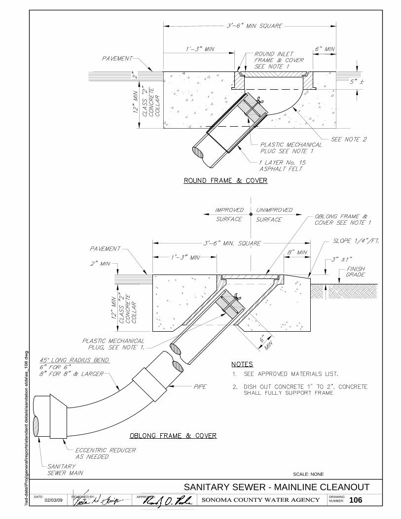
106SANITARY SEWER - MAINLINE CLEANOUT
DRAWINGNUMBER:
SCALE: NONE
REVIEWED BY: APPROVED:02/03/09
DATE:
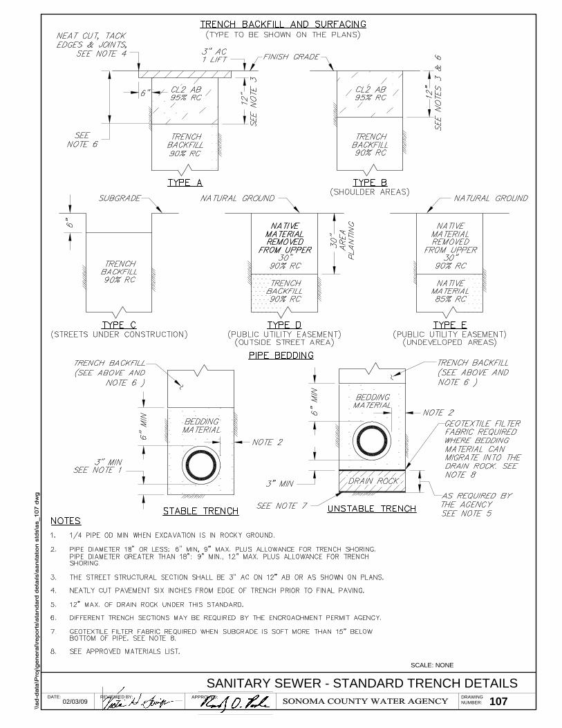
107SANITARY SEWER - STANDARD TRENCH DETAILS
DRAWINGNUMBER:
SCALE: NONE
REVIEWED BY: APPROVED:02/03/09
DATE:

108SANITARY SEWER - IMPORTED MATERIALS
DRAWINGNUMBER:
SCALE: NONE
REVIEWED BY: APPROVED:02/03/09
DATE:
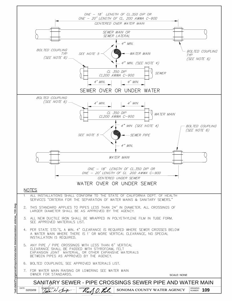
DRAWINGNUMBER:
SCALE: NONE
REVIEWED BY: APPROVED:02/03/09
DATE: 109SANITARY SEWER - PIPE CROSSINGS SEWER PIPE AND WATER MAIN

DRAWINGNUMBER:
SCALE: NONE
REVIEWED BY: APPROVED:02/03/09
DATE: 110SANITARY SEWER - MISCELLANEOUS PIPE CROSSINGS
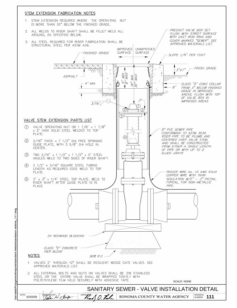
DRAWINGNUMBER:
SCALE: NONE
REVIEWED BY: APPROVED:02/03/09
DATE: 111SANITARY SEWER - VALVE INSTALLATION DETAIL

DRAWINGNUMBER:
SCALE: NONE
REVIEWED BY: APPROVED:02/03/09
DATE: 112SANITARY SEWER - ABANDONED MANHOLE DETAIL

DRAWINGNUMBER:
SCALE: NONE
REVIEWED BY: APPROVED:02/03/09
DATE: 113SANITARY SEWER - ABANDONED PIPE DETAIL
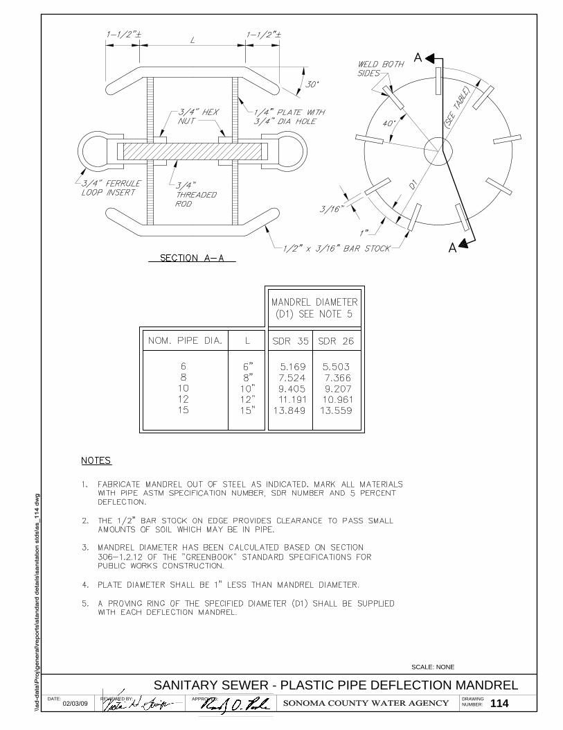
DRAWINGNUMBER:
SCALE: NONE
REVIEWED BY: APPROVED:02/03/09
DATE: 114SANITARY SEWER - PLASTIC PIPE DEFLECTION MANDREL

DRAWINGNUMBER:
SCALE: NONE
REVIEWED BY: APPROVED:02/03/09
DATE: 115SANITARY SEWER - WATER TEST - ALLOWABLE LEAKAGE
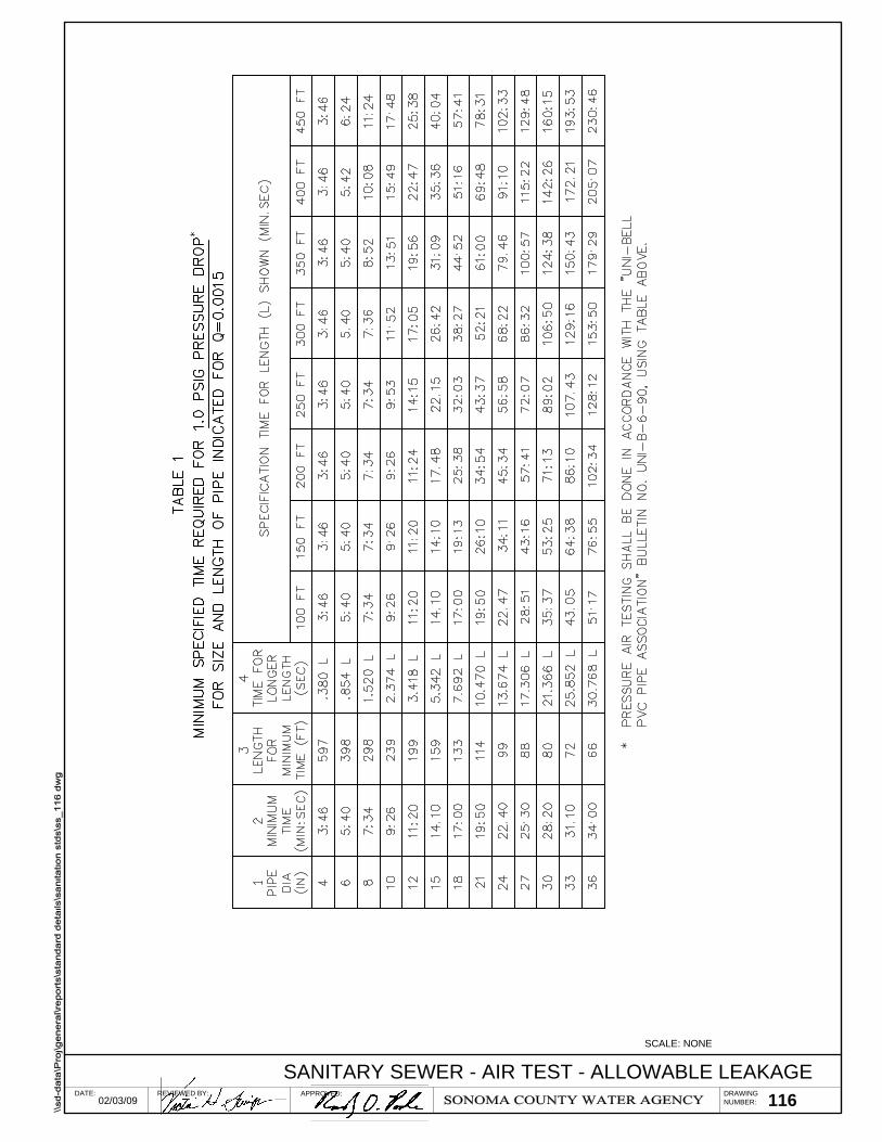
DRAWINGNUMBER:
SCALE: NONE
REVIEWED BY: APPROVED:02/03/09
DATE: 116SANITARY SEWER - AIR TEST - ALLOWABLE LEAKAGE

DRAWINGNUMBER:
SCALE: NONE
REVIEWED BY: APPROVED:02/03/09
DATE: 117-ASANITARY SEWER - SINGLE STAGE GREASE INTERCEPTOR

DRAWINGNUMBER:
SCALE: NONE
REVIEWED BY: APPROVED:02/03/09
DATE: 117-BSANITARY SEWER - TWO STAGE GREASE INTERCEPTOR

DRAWINGNUMBER:
SCALE: NONE
REVIEWED BY: APPROVED:02/03/09
DATE: 118-ASANITARY SEWER - THREE STAGE SAND AND GREASE INTERCEPTOR

DRAWINGNUMBER:
SCALE: NONE
REVIEWED BY: APPROVED:02/03/09
DATE: 118-BSANITARY SEWER - THREE STAGE GREASE INTERCEPTOR

119SANITARY SEWER - MONITORING SAMPLING BOX
DRAWINGNUMBER:
SCALE: NONE
REVIEWED BY: APPROVED:02/03/09
DATE:

120-ASANITARY SEWER - SAMPLING BOX
DRAWINGNUMBER:
SCALE: NONE
REVIEWED BY: APPROVED:02/03/09
DATE:

120-BSANITARY SEWER - SAMPLING BOX
DRAWINGNUMBER:
SCALE: NONE
REVIEWED BY: APPROVED:02/03/09
DATE:
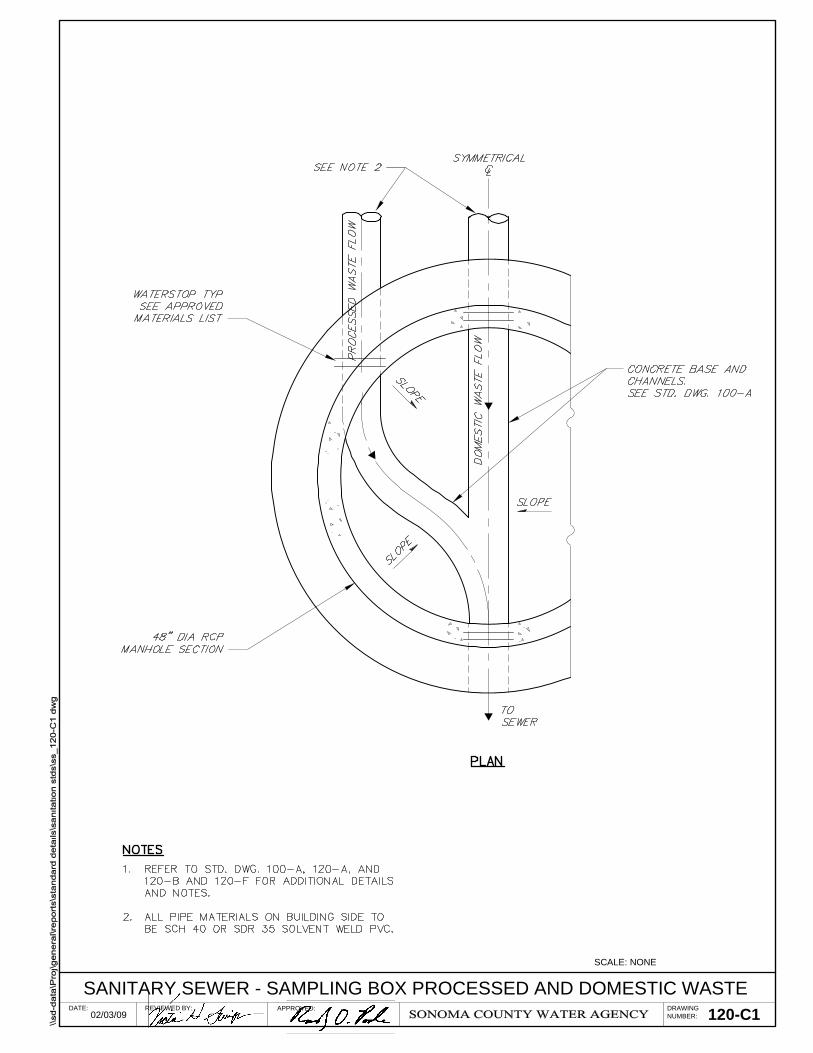
DRAWINGNUMBER:
SCALE: NONE
REVIEWED BY: APPROVED:02/03/09
DATE: 120-C1SANITARY SEWER - SAMPLING BOX PROCESSED AND DOMESTIC WASTE

DRAWINGNUMBER:
SCALE: NONE
REVIEWED BY: APPROVED:02/03/09
DATE: 120-C2

120-D1SANITARY SEWER - TRASH ENCLOSURE
DRAWINGNUMBER:
SCALE: NONE
REVIEWED BY: APPROVED:02/03/09
DATE:

DRAWINGNUMBER:
SCALE: NONE
REVIEWED BY: APPROVED:02/03/09
DATE: 120-D2SANITARY SEWER - TRASH ENCLOSURE WITH SEWER CONNECTION
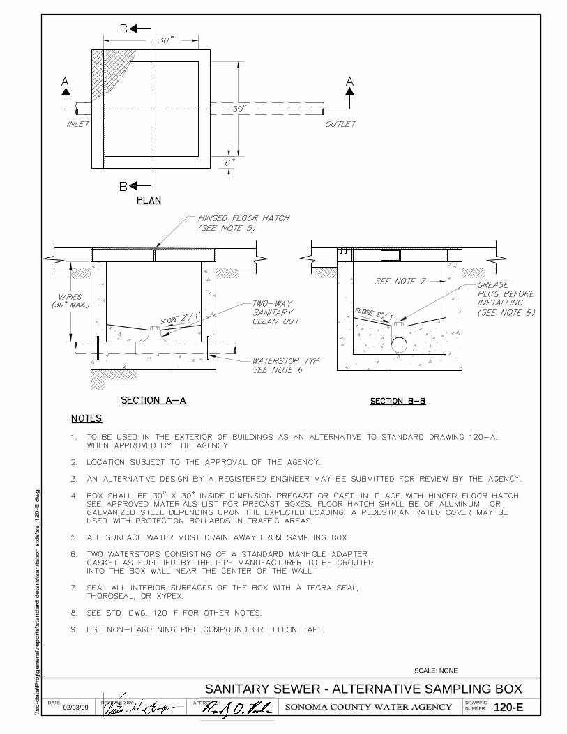
DRAWINGNUMBER:
SCALE: NONE
REVIEWED BY: APPROVED:02/03/09
DATE: 120-ESANITARY SEWER - ALTERNATIVE SAMPLING BOX

DRAWINGNUMBER:
SCALE: NONE
REVIEWED BY: APPROVED:02/03/09
DATE: 120-FSANITARY SEWER - SAMPLING BOX BUILDING NOTES

DRAWINGNUMBER:
SCALE: NONE
REVIEWED BY: APPROVED:02/03/09
DATE: 121SANITARY SEWER - 4 INCH AND 6 INCH SERVICE LATERAL AND CLEANOUT

DRAWINGNUMBER:
SCALE: NONE
REVIEWED BY: APPROVED:02/03/09
DATE: 122SANITARY SEWER - TYPICAL BUILDING SEWER CONNECTION DETAILS

DRAWINGNUMBER:
SCALE: NONE
REVIEWED BY: APPROVED:02/03/09
DATE: 123SANITARY SEWER - BUILDING CLEANOUT DETAIL AT BUILDING

SANITARY SEWER - RECREATIONAL VEHICLE DISPOSAL FACILITYDRAWINGNUMBER:
SCALE: NONE
REVIEWED BY: APPROVED:02/03/09
DATE: 124SANITARY SEWER - RECREATIONAL VEHICLE DISPOSAL FACILITY

125SANITARY SEWER - MOBILE HOME CONNECTION
DRAWINGNUMBER:
SCALE: NONE
REVIEWED BY: APPROVED:02/03/09
DATE:
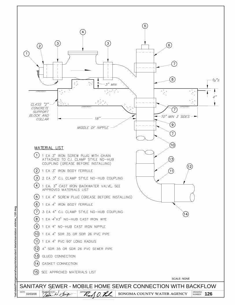
DRAWINGNUMBER:
SCALE: NONE
REVIEWED BY: APPROVED:02/03/09
DATE: 126SANITARY SEWER - MOBILE HOME SEWER CONNECTION WITH BACKFLOW

DRAWINGNUMBER:
SCALE: NONE
REVIEWED BY: APPROVED:02/03/09
DATE: 127SANITARY SEWER - BACKFLOW CHECK VALVE INSTALLATION DETAIL
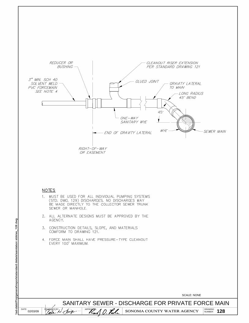
DRAWINGNUMBER:
SCALE: NONE
REVIEWED BY: APPROVED:02/03/09
DATE: 128SANITARY SEWER - DISCHARGE FOR PRIVATE FORCE MAIN

DRAWINGNUMBER:
SCALE: NONE
REVIEWED BY: APPROVED:02/03/09
DATE: 129SANITARY SEWER - PRIVATE INDIVIDUAL PUMPING SYSTEM DETAIL

DRAWINGNUMBER:
SCALE: NONE
REVIEWED BY: APPROVED:02/03/09
DATE: 130SANITARY SEWER - BUILDING CLEANOUT DETAIL AT BUILDING

DRAWINGNUMBER:
SCALE: NONE
REVIEWED BY: APPROVED:02/03/09
DATE: 131

DRAWINGNUMBER:
SCALE: NONE
REVIEWED BY: APPROVED:02/03/09
DATE: 132SANITARY SEWER - TRAFFIC AREA BUILDING CLEANOUT DETAIL

DRAWINGNUMBER:
SCALE: NONE
REVIEWED BY: APPROVED:02/03/09
DATE: 133SANITARY SEWER - BUILDING SEWER TRENCH DETAIL
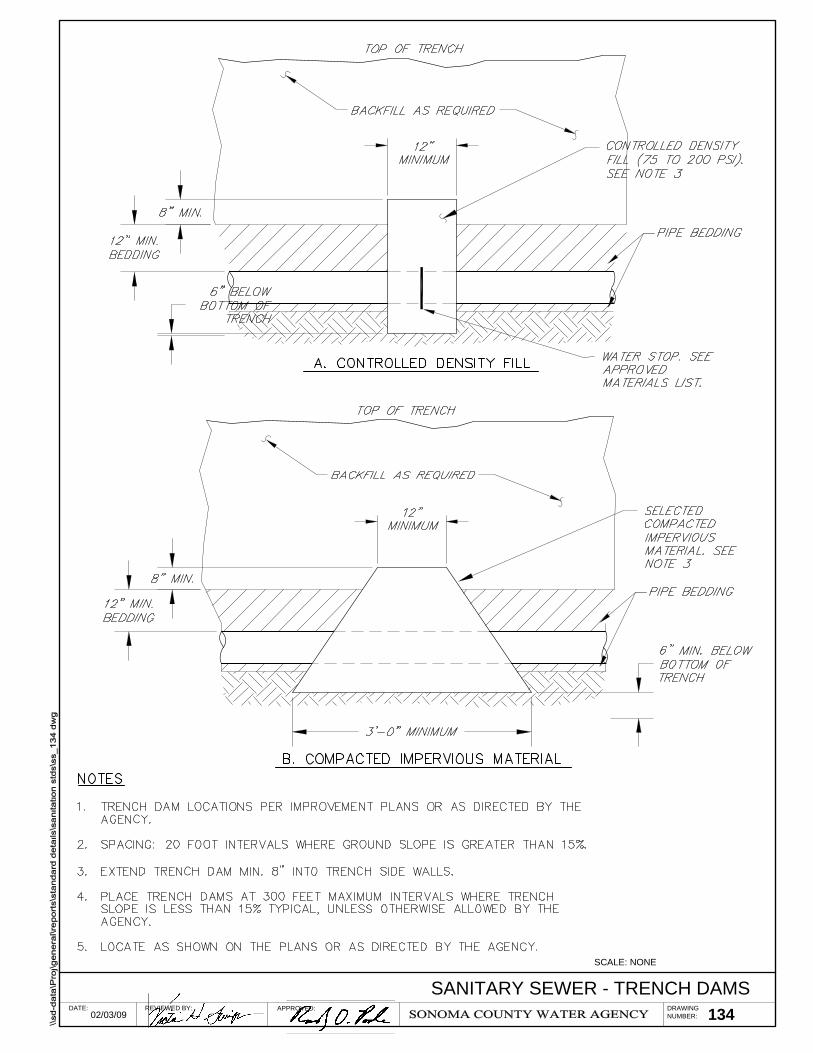
134SANITARY SEWER - TRENCH DAMS
DRAWINGNUMBER:
SCALE: NONE
REVIEWED BY: APPROVED:02/03/09
DATE:

135SANITARY SEWER - REDWOOD CHECK DAM
DRAWINGNUMBER:
SCALE: NONE
REVIEWED BY: APPROVED:02/03/09
DATE:

DRAWINGNUMBER:
SCALE: NONE
REVIEWED BY: APPROVED:02/03/09
DATE: 136SANITARY SEWER - ABOVE GROUND BUILDING SEWER

SECTION A-NOT TO SCALE
A
A
137SANITARY SEWER - TYPICAL CASING DETAIL
DRAWINGNUMBER:
SCALE: NONE
REVIEWED BY: APPROVED:02/03/09
DATE:

A. THIS PLAN IS BASED UPON NUMBERS FOUND IN THE 2000 U.S. CENSUS.
B. THIS IS THE FLOW FOUND IN THE BILLING BASIS TABLES FOR EACH SANITATION AREA.
C. THIS IS THE AVERAGE DRY WEATHER FLOW PER ESD BASED UPON FLOW RECORDS.
D. THE PEAK DRY WEATHER FLOW IS DETERMINED BY MULTIPLYING THE ADWF (C) BYTHE PEAK TO AVERAGE RATIO (E).
E. THE PEAK TO AVERAGE RATIO WAS DETERMINED BY MULTIPLYING THE ADWF (C) BY ACONSTANT K PRODUCED BY THE FORMULA:
K=5.453/P0.0963 WHERE P=ESTIMATED POPULATION
F. THIS NUMBER COMES FROM THE AGENCY'S MASTER LIST OF BILLING RECORDS ANDIS THE TOTAL NUMBER OF ESDs LISTED FOR EACH SANITATION AREA.
G. THIS IS ARRIVED AT BY MULTIPLYING THE NUMBER OF PEOPLE PER ESD (A) TIMESTHE CONNECTED ESD LOAD (F)
H. PDWF PLUS 800 GALLONS PER ACRE PER DAY RAINFALL DERIVED INFLOW ANDINFILTRATION PRODUCES THE DESIGN PEAK WET WEATHER FLOW (DWWF).
EFFECTIVE JANUARY 1, 2009
1. THE NUMBERS AND FORMULAS USED IN THISTABLE ARE SUBJECT TO CHANGE.
2. PDWF PLUS 800 GALLONS PER ACRE PER DAYRAINFALL DERIVED INFLOW AND INFILTRATIONPRODUCES THE DESIGN PEAK WET WEATHERFLOW (PWWF).
DRAWINGNUMBER:
SCALE: NONE
REVIEWED BY: APPROVED:02/03/09
DATE: 138SANITARY SEWER - SANITARY AREA FLOW CHARACTERISTICS