Embed Size (px)
Citation preview

PDHonline Course C226 (6 PDH)
Design and Construction ofEarth and Rock Fill Dams
2012
Instructor: Jeffrey Havelin, PE
PDH Online | PDH Center5272 Meadow Estates Drive
Fairfax, VA 22030-6658Phone & Fax: 703-988-0088
www.PDHonline.orgwww.PDHcenter.com
An Approved Continuing Education Provider

US Army Corps of Engineers®
ENGINEERING AND DESIGN
EM 1110-2-230030 July 2004
General Design and Construction Considerations for Earth and Rock-Fill Dams
ENGINEER MANUAL

AVAILABILITY
Electronic copies of this and other U.S. Army Corps of Engi-neers (USACE) publications are available on the Internet at http://www.usace.army.mil/inet/usace-docs/. This site is the only repository for all official USACE engineer regulations, circu-lars, manuals, and other documents originating from HQUSACE. Publications are provided in portable document format (PDF).

i
DEPARTMENT OF THE ARMY EM 1110-2-2300 U.S. Army Corps of Engineers CECW-EG Washington, DC 20314-1000 Manual No. 1110-2-2300 30 July 2004
Engineering and Design GENERAL DESIGN AND CONSTRUCTION CONSIDERATIONS
FOR EARTH AND ROCK-FILL DAMS Subject Paragraph Page Chapter 1 Introduction Purpose............................................................................................................................1-1 1-1 Applicability ...................................................................................................................1-2 1-1 References.......................................................................................................................1-3 1-1 Overview of Manual .......................................................................................................1-4 1-1 Chapter 2 General Considerations General............................................................................................................................2-1 2-1 Civil Works Project Process ...........................................................................................2-2 2-2 Types of Embankment Dams..........................................................................................2-3 2-3 Basic Requirements ........................................................................................................2-4 2-5 Selection of Embankment Type......................................................................................2-5 2-7 Environmental Considerations........................................................................................2-6 2-8 Chapter 3 Field Investigations and Laboratory Testing Geological and Subsurface Explorations and Field Tests...............................................3-1 3-1 Laboratory Testing..........................................................................................................3-2 3-4 Chapter 4 General Design Considerations General............................................................................................................................4-1 4-1 Freeboard ........................................................................................................................4-2 4-3 Top Width .......................................................................................................................4-3 4-3 Alignment .......................................................................................................................4-4 4-3 Embankment ...................................................................................................................4-5 4-3 Abutments .......................................................................................................................4-6 4-3 Performance Parameters .................................................................................................4-7 4-4 Earthquake Effects ..........................................................................................................4-8 4-5 Coordination Between Design and Construction............................................................4-9 4-5 Value Engineering Proposals ..........................................................................................4-10 4-6 Partnering Between the Owner and Contractor ..............................................................4-11 4-6
EM 1110-2-2300 30 Jul 04
ii
Subject Paragraph Page Modifications to Embankment Dams to Accommodate New or Revised Inflow Design Floods or to Provide Additional Storage for Water Supply or Other Purposes............................................................................................................4-12 4-7 Chapter 5 Foundation and Abutment Preparation Preparation ......................................................................................................................5-1 5-1 Strengthening the Foundation .........................................................................................5-2 5-3 Dewatering the Working Area ........................................................................................5-3 5-3 Chapter 6 Seepage Control General............................................................................................................................6-1 6-1 Embankment ...................................................................................................................6-2 6-1 Earth Foundations ...........................................................................................................6-3 6-1 Rock Foundations ...........................................................................................................6-4 6-5 Abutments .......................................................................................................................6-5 6-6 Adjacent to Outlet Conduits............................................................................................6-6 6-6 Beneath Spillways and Stilling Basins............................................................................6-7 6-6 Seepage Control Against Earthquake Effects .................................................................6-8 6-7 Chapter 7 Embankment Design Embankment Materials ...................................................................................................7-1 7-1 Zoning.............................................................................................................................7-2 7-2 Cracking..........................................................................................................................7-3 7-3 Filter Design....................................................................................................................7-4 7-8 Consolidation and Excess Porewater Pressures ..............................................................7-5 7-8 Embankment Slopes and Berms .....................................................................................7-6 7-9 Embankment Reinforcement ..........................................................................................7-7 7-9 Compaction Requirements..............................................................................................7-8 7-10 Slope Protection ..............................................................................................................7-9 7-14 Chapter 8 Appurtenant Structures Outlet Works...................................................................................................................8-1 8-1 Spillway ..........................................................................................................................8-2 8-1 Other Important Considerations......................................................................................8-3 8-2 Chapter 9 General Construction Considerations General............................................................................................................................9-1 9-1 Obtaining Quality Construction ......................................................................................9-2 9-1 Stage Construction ..........................................................................................................9-3 9-2 Stream Diversion ............................................................................................................9-4 9-2 Closure Section ...............................................................................................................9-5 9-3 Construction/Design Interface ........................................................................................9-6 9-4 Visual Observations ........................................................................................................9-7 9-4 Compaction Control........................................................................................................9-8 9-4

EM 1110-2-2300 30 Jul 04
iii
Subject Paragraph Page Initial Reservoir Filling...................................................................................................9-9 9-5 Construction Records and Reports..................................................................................9-10 9-6 Chapter 10 Instrumentation General............................................................................................................................10-1 10-1 Instrumentation Plan and Records ..................................................................................10-2 10-1 Types of Instrumentation ................................................................................................10-3 10-3 Discussion of Devices.....................................................................................................10-4 10-3 Measurements of Seepage Quantities .............................................................................10-5 10-4 Automated Data Acquisition Systems ............................................................................10-6 10-4 Appendix A References Appendix B Filter Design Appendix C Slope Protection Appendix D Automatic Data Acquisition Systems Appendix E Process for Establishing Performance Parameters Appendix F Methods of Dam Raising


EM 1110-2-2300 30 Jul 04
1-1
Chapter 1 Introduction 1-1. Purpose This manual presents fundamental principles underlying the design and construction of earth and rock-fill dams. The general principles presented herein are also applicable to the design and construction of earth levees. The construction of earth dams by hydraulic means was curtailed in the 1940's due to economic considerations and liquefaction concerns during earthquake loading and are not discussed herein. 1-2. Applicability This manual applies to HQUSACE elements, major subordinate commands, districts, laboratories, and field operating activities having responsibility for the design and construction of earth and rock-fill dams. 1-3. References Required and related publications are listed in Appendix A. 1-4. Overview of Manual The objective of this manual is to present guidance on the design, construction, and performance monitoring of and modifications to embankment dams. The manual presents general guidance and is not intended to supplant the creative thinking and judgment of the designer for a particular project. The increased development and expansion of the population in the Nation’s watersheds have created a definite need to develop additional water supply. In many areas the existing national infrastructure cannot meet these needs. The increase in urban development has also had a negative impact on water quality. The public is asking that preservation of the environment be an equal goal with the economic benefits of water resources projects. Since the current infrastructure is not meeting public needs, this situation is placing lives, livelihood, and property at risk. Several options are available to provide the additional quantity of water. The simplest and most cost-effective method to obtain the quantities needed is to add additional storage at existing dams. Many of the Nation’s existing water resources projects must be modified to add the additional purpose of water supply. In the future, USACE designers will be challenged with requests by the customers and sponsors to modify existing dams to add water supply to other purposes of existing dams. These modifica-tions must include environmental considerations and mitigation.


EM 1110-2-2300 30 Jul 04
2-1
Chapter 2 General Considerations 2-1. General a. Introduction. The successful design, construction, and operation of a reservoir project over the full range of loading require a comprehensive site characterization, a detailed design of each feature, construction supervision, measurement and monitoring of the performance, and the continuous evaluation of the project features during operation. The design and construction of earth and rock-fill dams are complex because of the nature of the varying foundation conditions and range of properties of the materials available for use in the embankment. The first step is to conduct detailed geological and subsurface explorations, which characterize the foundation, abutments, and potential borrow areas. The next step is to conduct a study of the type and physical properties of materials to be placed in the embankment. This study should include a determination of quantities and the sequence in which they will become available. The design should include all of the studies, testing, analyses, and evaluations to ensure that the embankment meets all technical criteria and the requirements of a dam as outlined in b below. Construction supervision, management, and monitoring of the embankment and appurtenant structures are a critical part of the overall project management plan. Once the project is placed into operation, observations, surveillance, inspections, and continuing evaluation are required to assure the satisfactory performance of the dam. b. Basic requirements of an embankment dam. Dams are a critical and essential part of the Nation’s infrastructure for the storage and management of water in watersheds. To meet the dam safety requirements, the design, construction, operation, and modification of an embankment dam must comply with the following technical and administrative requirements: (1) Technical requirements.
• The dam, foundation, and abutments must be stable under all static and dynamic loading
conditions.
• Seepage through the foundation, abutments, and embankment must be controlled and collected to ensure safe operation. The intent is to prevent excessive uplift pressures, piping of materials, sloughing removal of material by solution, or erosion of this material into cracks, joints, and cavities. In addition, the project purpose may impose a limitation on allowable quantity of seepage. The design should include seepage control measures such as foundation cutoffs, adequate and nonbrittle impervious zones, transition zones, drainage material and blankets, upstream impervious blankets, adequate core contact area, and relief wells.
• The freeboard must be sufficient to prevent overtopping by waves and include an allowance for
settlement of the foundation and embankment.
• The spillway and outlet capacity must be sufficient to prevent over-topping of the embankment by the reservoir.
(2) Administrative requirements.
• Environmental responsibility. • Operation and maintenance manual.
EM 1110-2-2300 30 Jul 04
2-2
• Monitoring and surveillance plan.
• Adequate instrumentation to monitor performance.
• Documentation of all the design, construction, and operational records.
• Emergency Action Plan: Identification, notification, and response subplan.
• Schedule for periodic inspections, comprehensive review, evaluation, and modifications as appropriate.
c. Embankment. Many different trial sections for the zoning of an embankment should be prepared to study utilization of fill materials; the influence of variations in types, quantities, or sequences of availability of various fill materials; and the relative merits of various sections and the influence of foundation condition. Although procedures for stability analyses (see EM 1110-2-1902 and Edris 1992) afford a convenient means for comparing various trial sections and the influence of foundation conditions, final selection of the type of embankment and final design of the embankment are based, to a large extent, upon experience and judgment. d. Features of design. Major features of design are required foundation treatment, abutment stability, seepage conditions, stability of slopes adjacent to control structure approach channels and stilling basins, stability of reservoir slopes, and ability of the reservoir to retain the water stored. These features should be studied with reference to field conditions and to various alternatives before initiating detailed stability or seepage analyses. e. Other considerations. Other design considerations include the influence of climate, which governs the length of the construction season and affects decisions on the type of fill material to be used, the relationship of the width of the valley and its influence on river diversion and type of dam, the planned utilization of the project (for example, whether the embankment will have a permanent pool or be used for short-term storage), the influence of valley configuration and topographic features on wave action and required slope protection, the seismic activity of the area, and the effect of construction on the environment. 2-2. Civil Works Project Process a. General. The civil works project process for a dam is continuous, although the level of intensity and technical detail varies with the progression through the different phases of the project development and imple-mentation. The phases of the process are reconnaissance, feasibility, preconstruction engineering and design (PED), construction, and finally the operation, maintenance, repair, replacement, and rehabilitation (OMRR&R). A brief summary of each phase, concerning the required engineering effort, is presented. A complete civil works project process is defined in ER 1110-2-1150. b. Reconnaissance phase. A reconnaissance study is conducted to determine whether or not the problem has a solution acceptable to local interests for which there is a Federal interest and if so whether planning should proceed to the feasibility phase. During the reconnaissance phase, engineering assessments of alternatives are made to determine if they will function safely, reliably, efficiently, and economically. Each alternative should be evaluated to determine if it is practical to construct, operate, and maintain. Several sites should be evaluated, and preliminary designs should be prepared for each site. These preliminary designs should include the foundation for the dam and appurtenant structures, the dam, and the reservoir rim. The reconnaissance phase ends with either execution of a Feasibility Cost Sharing Agreement or the major subordinate command (MSC) Commander's public notice for a report recommending no Federal action (ER 1110-2-1150). c. Feasibility phase. A feasibility study is conducted to investigate and recommend a solution to the problem based on technical evaluation of alternatives and includes a baseline cost estimate and a design and

EM 1110-2-2300 30 Jul 04
2-3
construction schedule which are the basis for congressional authorization. Engineering data and analyses in the feasibility phase shall be sufficient to develop the complete project schedule and baseline cost estimate with reasonable contingency factors. Results of the engineering studies are documented in an engineering appendix to the feasibility report. The outline of the engineering appendix is given in Appendix C of ER 1110-2-1150. An operation and maintenance plan for the project, including estimates of the Federal and non-Federal costs, will be developed. All of the project OMRR&R and dam safety requirements should be identified and discussed with the sponsor and state during the feasibility phase. d. Preconstruction engineering and design phase. The preconstruction engineering and design (PED) phase begins when the MSC Commander issues the public notice for the feasibility report and PED funds are allocated to the district. The PED ends with completion of the P&S for the first construction contract or as otherwise defined in the PED cost-sharing agreement. During the PED phase, the design is finalized, the plans and specifications (P&S) are prepared, and the construction contract is prepared for advertising. The design documentation report (DDR) covers the PED phase and the construction phase of the project. The DDR is not totally completed until after the P&S and construction are completed. During the PED, the production of DDR and related P&S shall proceed concurrently as one unified design phase. The design should be completed and documented in the DDR, in accordance with Appendix D, Content and Format of Design Documentation Report, ER 1110-2-1150. Any physical model studies required shall be conducted during the PED phase. In preparation for the beginning of each major construction contract, engineering will prepare a report, The Engineering Considerations and Instructions for Field Personnel, to provide field personnel the insight and background needed to review contractor proposals and resolve construction problems. Format of the report is presented in Appendix G, ER 1110-2-1150. e. Construction phase. This phase includes preparation of P&S for subsequent construction contracts, review of selected construction contracts, site visits, support for claims and modifications, development of opera-tion and maintenance (O&M) manuals, and preparation and maintenance of as-built drawings. Site visits must be made to verify that conditions match the assumptions used in designing the project features. Site visits may also be necessary to brief the construction division personnel on any technical issues which affect the construction. The O&M manual and water control manual will be completed and fully coordinated with the local sponsor during this phase of the project. As-built drawings are prepared and maintained by engineering during the construction phase (ER 1110-2-1150). f. Operation and maintenance phase. The project is operated, inspected, maintained, repaired, and rehabilitated by either the non-Federal sponsor or the Federal Government, depending upon the project purposes and the terms of the project cooperation agreement (PCA). For PCA projects and new dams turned over to others, the Corps needs to explain up front the O&M responsibilities, formal inspection requirements, and responsibilities to implement dam safety practices. Periodic inspections will be conducted to assess and evaluate the performance and safety of the project during its lifetime. Modifications to the features of a project which occur during the operating life of a project will be reflected in the as-built drawings (ER 1110-2-1150). 2-3. Types of Embankment Dams a. Introduction. The two principal types of embankment dams are earth and rock-fill dams, depending on the predominant fill material used. Some generalized sections of earth dams showing typical zoning for different types and quantities of fill materials and various methods for controlling seepage are presented in Figure 2-1. When practically only one impervious material is available and the height of the dam is relatively low, a homogeneous dam with internal drain may be used as shown in Figure 2-1a. The inclined drain serves to prevent the downstream slope from becoming saturated and susceptible to piping and/or slope failure and to intercept and prevent piping through any horizontal cracks traversing the width of the embankment. Earth dams with impervious cores, as shown in Figures 2-1b and 2-1c, are constructed when local borrow materials do not

EM 1110-2-2300 30 Jul 04
2-4
provide adequate quantities of impervious material. A vertical core located near the center of the dam is preferred over an inclined upstream core because the former provides higher contact pressure between the core and foundation to prevent leakage, greater stability under earthquake loading, and better access for remedial seepage control. An inclined upstream core allows the downstream portion of the embankment to be placed first and the core later and reduces the possibility of hydraulic fracturing. However, for high dams in steep-walled canyons the overriding consideration is the abutment topography. The objective is to fit the core to the topography in such a way to avoid divergence, abrupt topographic discontinuities, and serious geologic defects. For dams on pervious foundations, as shown in Figure 2-1d to 2-1f, seepage control is necessary to prevent excessive uplift pressures and piping through the foundation. The methods for control of underseepage in dam foundations are horizontal drains, cutoffs (compacted backfill trenches, slurry walls, and concrete walls), upstream impervious blankets, downstream seepage berms, toe drains, and relief wells. Rock-fill dams may be economical due to large quantities of rock available from required excavation and/or nearby borrow sources, wet climate and/or short construction season prevail, ability to place rock fill in freezing climates, and ability to conduct foundation grouting with simultaneous placement of rock fill for sloping core and decked dams (Walker 1984). Two generalized sections of rock-fill dams are shown in Figure 2-2. A rock-fill dam with steep slopes requires better foundation conditions than an earth dam, and a concrete dam (or roller-compacted concrete dam) requires better foundation conditions than a rock-fill dam. The design and construction of seepage control measures for dams are given in EM 1110-2-1901. b. Earth dams. An earth dam is composed of suitable soils obtained from borrow areas or required exca-vation and compacted in layers by mechanical means. Following preparation of a foundation, earth from borrow areas and from required excavations is transported to the site, dumped, and spread in layers of required depth. The soil layers are then compacted by tamping rollers, sheepsfoot rollers, heavy pneumatic-tired rollers, vibratory rollers, tractors, or earth-hauling equipment. One advantage of an earth dam is that it can be adapted to a weak foundation, provided proper consideration is given to thorough foundation exploration, testing, and design. c. Rock-fill dams. A rock-fill dam is one composed largely of fragmented rock with an impervious core. The core is separated from the rock shells by a series of transition zones built of properly graded material. A membrane of concrete, asphalt, or steel plate on the upstream face should be considered in lieu of an impervious earth core only when sufficient impervious material is not available (such was the case at R. W. Bailey Dam; see Beene and Pritchett 1985). However, such membranes are susceptible to breaching as a result of settlement. The rock-fill zones are compacted in layers 12 to 24 in. thick by heavy rubber-tired or steel-wheel vibratory rollers. It is often desirable to determine the best methods of construction and compaction on the basis of test quarry and test fill results. Dumping rock fill and sluicing with water, or dumping in water, is generally acceptable only in constructing cofferdams that are not to be incorporated in the dam embankment. Free-draining, well-compacted rock fill can be placed with steep slopes if the dam is on a rock foundation. If it is necessary to place rock-fill on an earth or weathered rock foundation, the slopes must, of course, be much flatter, and transition zones are required between the foundation and the rock fill. Materials for rock-fill dams range from sound free-draining rock to the more friable materials such as sandstones and silt-shales that break down under handling and compacting to form an impervious to semipervious mass. The latter materials, because they are not completely free-draining and lack the shear strength of sound rock fill, are often termed “random rock” and can be used successfully for dam construction, but, because of stability and seepage considerations, the embankment design using such materials is similar to that for earth dams.

EM 1110-2-2300 30 Jul 04
2-5
Figure 2-1. Types of earth dam sections 2-4. Basic Requirements a. Criteria. The following criteria must be met to ensure satisfactory earth and rock-fill structures: (1) The embankment, foundation, and abutments must be stable under all conditions of construction and reservoir operation including seismic.

EM 1110-2-2300 30 Jul 04
2-6
Figure 2-2. Two types of rock-fill dams (2) Seepage through the embankment, foundation, and abutments must be collected and controlled to prevent excessive uplift pressures, piping, sloughing, removal of material by solution, or erosion of material by loss into cracks, joints, and cavities. In addition, the purpose of the project may impose a limitation on the allowable quantity of seepage. The design should consider seepage control measures such as foundation cutoffs, adequate and nonbrittle impervious zones, transition zones, drainage blankets, upstream impervious blankets, and relief wells. (3) Freeboard must be sufficient to prevent overtopping by waves and include an allowance for the normal settlement of the foundation and embankment as well as for seismic effects where applicable. (4) Spillway and outlet capacity must be sufficient to prevent overtopping of the embankment. b. Special attention. Special attention should be given to possible development of pore pressures in foundations, particularly in stratified compressible materials, including varved clays. High pore pressures may be induced in the foundation, beyond the toes of the embankment where the weight of the dam produces little or no vertical loading. Thus, the strengths of foundation soils outside of the embankment may drop below their original in situ shear strengths. When this type of foundation condition exists, instrumentation should be installed during construction (see Chapter 10).
EM 1110-2-2300 30 Jul 04
2-7
2-5. Selection of Embankment Type a. General. Site conditions that may lead to selection of an earth or a rock-fill dam rather than a concrete dam (or roller-compacted concrete dam) include a wide stream valley, lack of firm rock abutments, considerable depths of soil overlying bedrock, poor quality bedrock from a structural point of view, availability of sufficient quantities of suitable soils or rock fill, and existence of a good site for a spillway of sufficient capacity. b. Topography. Topography, to a large measure, dictates the first choice of type of dam. A narrow V-shaped valley with sound rock in abutments would favor an arch dam. A relatively narrow valley with high, rocky walls would suggest a rock fill or concrete dam (or roller-compacted concrete). Conversely, a wide valley with deep overburden would suggest an earth dam. Irregular valleys might suggest a composite structure, partly earth and partly concrete. Composite sections might also be used to provide a concrete spillway while the rest of the dam is constructed as an embankment section (Golze 1977, Singh and Sharma 1976, Goldin and Rasskazov 1992). The possibility of cracking resulting from arching in narrow valleys and shear cracks in the vicinity of steep abutments must be investigated and may play a role in the selection of the type of dam (Mitchell 1983). At Mud Mountain Dam, arching of the soil core material within a narrow, steep-sided canyon reduced stresses making the soil susceptible to hydraulic fracturing, cracking, and piping (Davidson, Levallois, and Graybeal 1992). Haul roads into narrow valleys may be prohibited for safety and/or environmental reasons. At Abiquiu and Warm Springs Dams, borrow material was transported by a belt conveyor system (Walker 1984). Topography may also influence the selection of appurtenant structures. Natural saddles may provide a spillway location. If the reservoir rim is high and unbroken, a chute or tunnel spillway may be necessary (Bureau of Reclamation 1984). c. Geology and foundation conditions. The geology and foundation conditions at the damsite may dictate the type of dam suitable for that site. Competent rock foundations with relatively high shear strength and resis-tance to erosion and percolation offer few restrictions as to the type of dam that can be built at the site. Gravel foundations, if well compacted, are suitable for earth or rock-fill dams. Special precautions must be taken to provide adequate seepage control and/or effective water cutoffs or seals. Also, the liquefaction potential of gravel foundations should be investigated (Sykora et al. 1992). Silt or fine sand foundations can be used for low concrete (or roller-compacted concrete) and earth dams but are not suitable for rock-fill dams. The main problems include settlement, prevention of piping, excessive percolation losses, and protection of the foundation at the downstream embankment toe from erosion. Nondispersive clay foundations may be used for earth dams but require flat embankment slopes because of relatively low foundation shear strength. Because of the require-ment for flatter slopes and the tendency for large settlements, clay foundations are generally not suitable for concrete (or roller-compacted concrete) or rock-fill dams (Golze 1977, Bureau of Reclamation 1984). d. Materials available. The most economical type of dam will often be one for which materials can be found within a reasonable haul distance from the site, including material which must be excavated for the dam foundation, spillway, outlet works, powerhouses, and other appurtenant structures. Materials which may be available near or on the damsite include soils for embankments, rock for embankments and riprap, and concrete aggregate (sand, gravel, and crushed stone). Materials from required excavations may be stockpiled for later use. However, greater savings will result if construction scheduling allows direct use of required excavations. If suit-able soils for an earth-fill dam can be found in nearby borrow pits, an earth dam may prove to be more econom-ical. The availability of suitable rock may favor a rock-fill dam. The availability of suitable sand and gravel for concrete at a reasonable cost locally or onsite is favorable to use for a concrete (or roller-compacted concrete) dam (Golze 1977, Bureau of Reclamation 1984). e. Spillway. The size, type, and restrictions on location of the spillway are often controlling factors in the choice of the type of dam. When a large spillway is to be constructed, it may be desirable to combine the spillway and dam into one structure, indicating a concrete overflow dam. In some cases where required

EM 1110-2-2300 30 Jul 04
2-8
excavation from the spillway channel can be utilized in the dam embankment, an earth or rock-fill dam may be advantageous (Golze 1977, Bureau of Reclamation 1984). f. Environmental. Recently environmental considerations have become very important in the design of dams and can have a major influence on the type of dam selected. The principal influence of environmental con-cerns on selection of a specific type of dam is the need to consider protection of the environment, which can affect the type of dam, its dimensions, and location of the spillway and appurtenant facilities (Golze 1977). g. Economic. The final selection of the type of dam should be made only after careful analysis and com-parison of possible alternatives, and after thorough economic analyses that include costs of spillway, power and control structures, and foundation treatment. 2-6. Environmental Considerations Public Law 91-190, National Environmental Policy Act of 1969, as amended, and the Clean Water Act of 1977 established the national policy for promoting efforts that will prevent or mitigate damage to the Nation’s rivers and to the environment. The goal is to achieve clean and healthy watersheds that support aquatic life, economic development, and human needs. Managing water resources in a river basin has an impact on its natural water cycle. The scale of the impact depends on the actual size and natural condition of the area to be developed and the extent of development. Mitigation measures are essential elements in the planning, design, construction, and operation of a project, including clearing of vegetation in the area to be flooded, multilevel outlet structures to optimize downstream water temperature and quality, provisions for the migration of fish and other aquatic organisms, and operational rules for regulating downstream flows at critical times to protect habitat for reproduction or migratory routes. Appropriate site selection, together with the implementation of these techniques, will result in both new and rehabilitated projects that minimize unacceptable environmental impacts. Environmental conservation includes mitigation and enhancement for new projects, maintaining the existing conditions and restoration where appropriate.

EM 1110-2-2300 30 Jul 04
3-1
Chapter 3 Field Investigations and Laboratory Testing 3-1. Geological and Subsurface Explorations and Field Tests a. General requirements. (1) Geological and subsurface investigations at the sites of structures and at possible borrow areas must be adequate to determine suitability of the foundation and abutments, required foundation treatment, excavation slopes, and availability and characteristics of embankment materials. This information frequently governs selection of a specific site and type of dam. Required foundation treatment may be a major factor in determining project feasibility. These investigations should cover classification, physical properties, location and extent of soil and rock strata, and variations in piezometric levels in groundwater at different depths. (2) A knowledge of the regional and local geology is essential in developing a plan of subsurface investiga-tion, interpreting conditions between and beyond boring locations, and revealing possible sources of trouble. (3) The magnitude of the foundation exploration program is governed principally by the complexity of the foundation problem and the size of the project. Explorations of borrow and excavation areas should be under-taken early in the investigational program so that quantities and properties of soils and rock available for embankment construction can be determined before detailed studies of embankment sections are made. (4) Foundation rock characteristics such as depth of bedding, solution cavities, fissures, orientation of joints, clay seams, gouge zones, and faults which may affect the stability of rock foundations and slopes, particularly in association with seepage, must be investigated to determine the type and scope of treatment required. Further-more, foundations and slopes of clay shales (compaction shales) often undergo loss in strength under reduction of loading or by disintegration upon weathering. Careful investigation of stability aspects of previous excavations and of natural slopes should be made. Foundations of clay shales should be assumed to contain sufficient fissures so that the residual shear strength is applicable unless sufficient investigations are made to prove otherwise. (5) Procedures for surface and subsurface geotechnical investigations and geophysical explorations are given in EM 1110-1-1804 and EM 1110-1-1802, respectively. Soil sampling equipment and procedures are dis-cussed in Appendix F, EM 1110-1-1804. b. Foundations. (1) The foundation is the valley floor and terraces on which the embankment and appurtenant structures rest. Comprehensive field investigations and/or laboratory testing are required where conditions such as those listed below are found in the foundation: (a) Deposits that may liquefy under earthquake shock or other stresses. (b) Weak or sensitive clays. (c) Dispersive soils. (d) Varved clays.

EM 1110-2-2300 30 Jul 04
3-2
(e) Organic soils. (f) Expansive soils, especially soils containing montmorillonite, vermiculite, and some mixed layer minerals. (g) Collapsible soils, usually fine-grained soils of low cohesion (silts and some clays) that have low natural densities and are susceptible to volume reductions when loaded and wetted. (h) Clay shales (compaction shales) that expand and lose strength upon unloading and/or exposure to weathering frequently have low in situ shear strengths. Although clay shales are most troublesome, all types of shales may present problems when they contain sheared and slickensided zones. (i) Limestones or calcareous soil deposits containing solution channels. (j) Gypsiferous rocks or soils. (k) Subsurface openings from abandoned mines. (l) Clay seams, shear zones, or mylonite seams in rock foundations. (m) Rock formations in which the rock quality designation (RQD) is low (less than 50 percent). (2) Subsurface investigation for foundations should develop the following data: (a) Subsurface profiles showing rock and soil materials and geological formations, including presence of faults, buried channels, and weak layers or zones. The RQD is useful in the assessment of the engineering quali-ties of bedrock (see Deere and Deere 1989). (b) Characteristics and properties of soils and the weaker types of rock. (c) Piezometric levels of groundwater in various strata and their variation with time including artisan pres-sures in rock or soil. (3) Exploratory adits in abutments, test pits, test trenches, large-diameter calyx holes, and large-diameter core boring are often necessary to satisfactorily investigate foundation and abutment conditions and to investigate reasons for core losses or rod droppings. Borehole photography and borehole television may also be useful. Core losses and badly broken cores often indicate zones that control the stability of a foundation or excavation slope and indicate a need for additional exploration. (4) Estimates of foundation permeability from laboratory tests are often misleading. It is difficult to obtain adequate subsurface data to evaluate permeability of gravelly strata in the foundation. Churn drilling has often proven satisfactory for this purpose. Pumping tests are required in pervious foundations to determine foundation permeability where seepage cutoffs are not provided or where deep foundation unwatering is required (see EM 1110-2-1901). c. Abutments. The abutments of a dam include that portion of the valley sides to which the ends of the dam join and also those portions beyond the dam which might present seepage or stability problems affecting the dam. Right and left abutments are so designated looking in a downstream direction. Abutment areas require essentially the same investigations as foundation areas. Serious seepage problems have developed in a number of cases because of inadequate investigations during design.

EM 1110-2-2300 30 Jul 04
3-3
d. Valley walls close to dam. Underground river channels or porous seepage zones may pass around the abutments. The valley walls immediately upstream and downstream from the abutment may have steep natural slopes and slide-prone areas that may be a hazard to tunnel approach and outlet channels. Such areas should be investigated sufficiently to determine if corrective measures are required. e. Spillway and outlet channel locations. These areas require comprehensive investigations of the orienta-tion and quality of rock or firm foundation stratum. Explorations should provide sufficient information on the overburden and rock to permit checking stability of excavated slopes and determining the best utilization of excavated material within the embankment. Where a spillway is to be located close to the end of a dam, the rock or earth mass between the dam and spillway must be investigated carefully. f. Saddle dams. The extent of foundation investigations required at saddle dams will depend upon the heights of the embankments and the foundation conditions involved. Exploratory borings should be made at all such structures. g. Reservoir crossings. The extent of foundation investigations required for highway and railway crossing of the reservoir depends on the type of structure, its height, and the foundation conditions. Such embankments may be subjected to considerable wave action and require slope protection. The slope protection will be designed for the significant wave based on a wave hind cast analysis as described in Appendix C and the referenced design document. Select the design water level and wind speed based on an analysis of the risk involved in failure of the embankment. For example, an evacuation route needs a higher degree of protection, perhaps equal to the dam face, than an access road to a recreational facility which may be cheaper to replace than to protect. h. Reservoir investigations. The sides and bottom of a reservoir should be investigated to determine if the reservoir will hold water and if the side slopes will remain stable during reservoir filling, subsequent drawdowns, and when subjected to earthquake shocks. Detailed analyses of possible slide areas should be made since large waves and overtopping can be caused by slides into the reservoir with possible serious consequences (see Hendron and Patton 1985a, 1985b). Water table studies of reservoir walls and surrounding area are useful, and should include, when available, data on local water wells. In limestone regions, sinks, caverns, and other solution features in the reservoir walls should be studied to determine if reservoir water will be lost through them. Areas containing old mines should be studied. In areas where there are known oil fields, existing records should be surveyed and reviewed to determine if plugging old wells or other treatment is required. i. Borrow areas and excavation areas. Borrow areas and areas of required excavation require investiga-tions to delineate usable materials as to type, gradation, depth, and extent; provide sufficient disturbed samples to determine permeability, compaction characteristics, compacted shear strength, volume change characteristics, and natural water contents; and provide undisturbed samples to ascertain the natural densities and estimated yield in each area. The organic content or near-surface borrow soils should be investigated to establish stripping requirements. It may be necessary to leave a natural impervious blanket over pervious material in upstream borrow areas for underseepage control. Of prime concern in considering possible valley bottom areas upstream of the embankment is flooding of these bottom areas. The sequence of construction and flooding must be studied to ensure that sufficient borrow materials will be available from higher elevations or stockpiles to permit completion of the dam. Sufficient borrow must be in a nonflooding area to complete the embankment after final closure, or provision must be made to stockpile low-lying material at a higher elevation. The extent of explorations will be determined largely by the degree of uniformity of conditions found. Measurements to determine seasonal fluctuation of the groundwater table and changes in water content should be made. Test pits, dozer trenches, and large-diameter auger holes are particularly valuable in investigating borrow areas and have additional value when left open for inspection by prospective bidders.

EM 1110-2-2300 30 Jul 04
3-4
j. Test quarries. The purposes of test quarries are to assist in cut slope design, evaluate the controlling geologic structure, provide information on blasting techniques and rock fragmentation, including size and shape of rocks, provide representative materials for test fills, give prospective bidders a better understanding of the drilling and blasting behavior of the rock, and determine if quarry-run rock is suitable or if grizzled rock-fill is required (see EM 1110-2-2302). k. Test fills. In the design of earth and rock-fill dams, the construction of test embankments can often be of considerable value, and in some cases is absolutely necessary. Factors involved in the design of earth and rock-fill dams include the most effective type of compaction equipment, lift thickness, number of passes, and placement water contents; the maximum particle size allowable; the amount of degradation or segregation during handling and compaction; and physical properties such as compacted density, permeability, grain-size distribu-tion, and shear strength of proposed embankment materials. Often this information is not available from pre-vious experience with similar borrow materials and can be obtained only by a combination of test fills and laboratory tests. Test fills can provide a rough estimate of permeability through observations of the rate at which water drains from a drill hole or from a test pit in the fill. To measure the field permeability of test fills, use a double-ring infiltrometer with a sealed inner ring (described in ASTM D 5093-90; see American Society for Testing and Materials 1990). It is important that test fills be performed on the same materials that will be used in construction of the embankment. The test fills shall be performed with the same quarry or borrow area materials which will be developed during construction and shall be compacted with various types of equipment to determine the most efficient type and required compaction effort. It is imperative that as much as possible all materials which may be encountered during construction be included in the test fills. Equipment known not to be acceptable should be included in the test fill specifications so as not to leave any “gray areas” for possible disagreements as to what will or will not be acceptable. Plans and specifications for test quarries and test fills of both earth and rock-fill materials are to be submitted to the Headquarters, U.S. Army Corps of Engineers, for approval. Test fills can often be included as part of access road construction but must be completed prior to completion of the embankment design. Summarized data from rock test fills for several Corps of Engineers projects are available (Hammer and Torrey 1973). l. Retention of samples. Representative samples from the foundation, abutment, spillway excavation, and borrow areas should be retained and stored under suitable conditions at least until construction has been completed and any claims settled. Samples should be available for examination or testing in connection with unexpected problems or contractor claims. 3-2. Laboratory Testing a. Presentation. A discussion of laboratory tests and presentation of test data for soils investigations in connection with earth dams are contained in EM 1110-2-1906. Additional information concerning laboratory compaction of earth-rock mixtures is given by Torrey and Donaghe (1991a, 1991b) and Torrey (1992). Applicability of the various types of shear tests to be used in stability analyses for earth dams is given in EM 1110-2-1902. Rock testing methods are given in the Rock Testing Handbook (U.S. Army Corps of Engineers 1990). Since shear strength tests are expensive and time-consuming, testing programs are generally limited to representative foundation and borrow materials. Samples to be tested should be selected only after careful analysis of boring logs, including index property determinations. Mixing of different soil strata for test specimens should be avoided unless it can be shown that mixing of different strata during construction will produce a fill with characteristics identical to those of the laboratory specimens. b. Procedure. Laboratory test procedures for determining all of the properties of rock-fill and earth-rock mixtures have not been standardized (see Torrey and Donaghe 1991a, 1991b; Torrey 1992). A few division laboratories have consolidation and triaxial compression equipment capable of testing 12-in.-diam specimens. c. Sample. For design purposes, shear strength of rock-fill and earth-rock mixtures should be determined in the laboratory on representative samples obtained from test fills. Triaxial tests should be performed on

EM 1110-2-2300 30 Jul 04
3-5
specimens compacted to in-place densities and having grain-size distributions paralleling test fill gradations. Core samples crushed in a jaw crusher or similar device should not be used because the resulting gradation, particle shape, and soundness are not typical of quarry-run material. For 12-in.-diameter specimens, maximum particle size should be 2 in.

EM 1110-2-2300 30 Jul 04
4-1
Chapter 4 General Design Considerations 4-1. General a. Embankment dams. Dams have become an integral part of the Nation’s infrastructure and play a significant and beneficial role in the development and management of water in river basins. Because of the wide variations in geologic settings in river basins, embankment dams will continue to provide the economic solutions for multipurpose projects. The design of an embankment dam is complex because of the unknowns of the foundation and materials available for construction. Past experience confirms that embankment dams can easily be “tailor-made” to fit the geologic site conditions and operational requirements for a project. There have been significant improvements in the design and construction practices and procedures for embankment dams. This trend will continue as more experience is gained from the actual performance of embankment dams under the full range of loading. Experience and judgment have always played a significant role in the design of embankment dams. The detailed analyses should be performed using a range of variables to allow an understanding of the sensitivity of the particular analysis to the material properties and the geometric configuration. Comparisons of actual versus predicted performance related to the most likely failure modes of a dam give the designers information to validate their experience and judgment. b. Causes of failure. (1) Since the failure of the Buffalo Creek Dam in West Virginia in 1972, there has been a considerable effort in the area of dam safety that created the inventory and developed a comprehensive dam safety program that included guidelines for inspection and evaluation and inspections to provide the governors with the status and condition of dams within their state. This effort was strengthened in 1996, when Public Law 104-303 established the National Dam Safety Program under the coordination of the Federal Emergency Management Agency (FEMA). (2) An understanding of the causes of failure is a critical element in the design and construction process for new dams and for the evaluation of existing dams. The primary cause of failure of embankment dams in the United States is overtopping as a result of inadequate spillway capacity. The next most frequent cause is seepage and piping. Seepage through the foundation and abutments is a greater problem than through the dam. Therefore, instrumentation in the abutments and foundation as well as observation and surveillance is the best method of detection. Other causes are slides (in the foundation and/or the embankment and abutments) and leakage from the outlet works conduit. In recent years, improved methods of stability analyses and better tools for site characterization and obtaining an understanding of material properties have reduced the frequency of failures from sliding stability.
c. Failure mode analysis. (1) New projects. The project requirements, geologic assessment and site characterization, unique project features, loading conditions, and the design criteria for the dam and appurtenant structures are the basis for the detailed project design. As the design progresses, an assessment of the materials distribution is made and a preliminary embankment section is established. The next step is to conduct a preliminary failure mode analysis. This consists of identifying the most likely modes of failure for the dam, foundation, abutments, and appurtenant structures as designed. It is important to have a thorough understanding of the historic causes of failure and their respective probabilities of occurrence. The failure modes should then be listed in the order of their likelihood of occurrence. During the final design, the failure modes are reviewed and updated. The results will be used to establish expected performance; identify the key parameters, measurements, and observations (performance parameters) needed to monitor performance of the dam; and establish the threshold
EM 1110-2-2300 30 Jul 04
4-2
of unsatisfactory performance. The results of this failure mode analysis will also provide input to the identification and notification subplan of the project Emergency Action Plan. During the final design, the performance parameters that will be used to measure and monitor the performance of the dam, foundation, abutments, and appurtenant structures are established. These performance criteria, generally expressed in terms of design limits and threshold performance limits, are refined as the project proceeds through more detailed levels of design, including design changes necessitated by site conditions more fully revealed during construction. (2) Existing projects. A similar failure mode analysis should be performed on all existing dams. The input is the original design criteria that were used, the loading and performance history, previous modifications, and current design criteria. d. Critical information for flood control operation. The successful operation of multipurpose projects during the flood control mission requires an understanding of the project features, their past performance, anticipated performance, and the ability to unload should indications of unsatisfactory performance develop. The critical information needed by the designer, operator, and dam safety officer is as follows: (1) Critical project information.
(a) Results of the failure mode analysis.
(b) Performance parameters.
(c) Threshold for increased monitoring.
(d) Threshold for any potential changes in reservoir operation to ensure safety.
• Return period of the event.
• Corresponding storage available.
(e) Drawdown capabilities.
• Full bank discharge (the discharge from the project that remains within the downstream riverbank. This is controlled by the lowest elevation of the top of river bank).
• Full discharge (the maximum discharge from the project with the reservoir at spillway crest.
Generally corresponds to minimum tailwater). (2) Information needed prior to and during an event.
(a) Projected inflow. (b) Corresponding reservoir levels and storage.
(c) Predicted performance for the projected reservoir levels.
(d) Reports from onsite monitoring.

EM 1110-2-2300 30 Jul 04
4-3
4-2. Freeboard a. Vertical distance. The term freeboard is applied to the vertical distance of a dam crest above the maxi-mum reservoir water elevation adopted for the spillway design flood. The freeboard must be sufficient to prevent overtopping of the dam by wind setup, wave action, or earthquake effects. Initial freeboard must allow for subsequent loss in height due to consolidation of embankment and/or foundation. The crest of the dam will generally include overbuild to allow for postconstruction settlements. The top of the core should also be overbuilt to ensure that it does not settle below its intended elevation. Net freeboard requirements (exclusive of earthquake considerations) can be determined using the procedures described in Saville, McClendon, and Cochran (1962). b. Elevation. In seismic zones 2, 3, and 4, as delineated in Figures A-1 through A-4 of ER 1110-2-1806, the elevation of the top of the dam should be the maximum determined by either maximum water surface plus conventional freeboard or flood control pool plus 3 percent of the height of the dam above streambed. This requirement applies regardless of the type of spillway. 4-3. Top Width The top width of an earth or rock-fill dam within conventional limits has little effect on stability and is governed by whatever functional purpose the top of the dam must serve. Depending upon the height of the dam, the mini-mum top width should be between 25 and 40 ft. Where the top of the dam is to carry a public highway, road and shoulder widths should conform to highway requirements in the locality with consideration given to requirements for future needs. The embankment zoning near the top is sometimes simplified to reduce the number of zones, each of which requires a minimum width to accommodate hauling and compaction equipment. 4-4. Alignment Axes of embankments that are long with respect to their heights may be straight or of the most economical align-ment fitting the topography and foundation conditions. Sharp changes in alignment should be avoided because downstream deformation at these locations would tend to produce tension zones which could cause concentration of seepage and possibly cracking and internal erosion. The axes of high dams in narrow, steep-sided valleys should be curved upstream so that downstream deflection under water loads will tend to compress the impervious zones longitudinally, providing additional protection against the formation of transverse cracks in the impervious zones. The radius of curvature forming the upstream arching of the dam in narrow valleys generally ranges from 1,000 to 3,000 ft. 4-5. Embankment Embankment sections adjacent to abutments may be flared to increase stability of sections founded on weak soils. Also, by flaring the core, a longer seepage path is developed beneath and around the embankment. 4-6. Abutments a. Alignments. Alignments should be avoided that tie into narrow ridges formed by hairpin bends in the river or that tie into abutments that diverge in the downstream direction. Grouting may be required to decrease seepage through the abutment (see paragraph 3-1c). Zones of structurally weak materials in abutments, such as weathered overburden and talus deposits, are not uncommon. It may be more economical to flatten embankment slopes to attain the desired stability than to excavate weak materials to a firm foundation. The horizontal permeability of undisturbed strata in the abutment may be much greater than the permeability of the compacted fill in the embankment; therefore, it may be possible to derive considerable benefit in seepage control from the

EM 1110-2-2300 30 Jul 04
4-4
blanketing effects of flared upstream embankment slopes. The design of a transition from the normal embankment slopes to flattened slopes is influenced by stability of sections founded on the weaker foundation materials, drainage provisions on the slopes and within the embankment, and the desirability of making a gradual transition without abrupt changes of section. Adequate surface drainage to avoid erosion should be provided at the juncture between the dam slope and the abutment. b. Abutment slopes. Where abutment slopes are steep, the core, filter, and transition zones of an embank-ment should be widened at locations of possible tension zones resulting from different settlements. Widening of the core may not be especially effective unless cracks developing in it tend to close. Even if cracks remain open, a wider core may tend to promote clogging. However, materials in the filter and transition zones are usually more self-healing, and increased widths of these zones are beneficial. Whenever possible, construction of the top 25 ft of an embankment adjacent to steep abutments should be delayed until significant embankment and foundation settlement have occurred. c. Settlement. Because large differential settlement near abutments may result in transverse cracking within the embankment, it may be desirable to use higher placement water contents (see paragraph 7-8a) combined with flared sections. 4-7. Performance Parameters a. Performance parameters are defined as those key indicators that are used to monitor and predict the response of the dam and foundation to the full range of loading for the critical conditions at a project. They document the performance history beginning with predictions made during design and construction through the actual performance based on observations and instrumentation. They also provide the historical data, quantitative values for specified limits, and complete records of performance for use in conventional evaluations and risk assessments. Performance parameters are characterized as follows:
• Optimizes and refines existing practices and procedures (not a new requirement).
• Establishes threshold limits for increased surveillance.
• Provides continuity over project life.
• Provides basis for emergency identification and response subplan of the project Emergency Action Plan.
• Provides the basic information and input for the justification of any required structural
modifications or operational changes to the project. b. Project requirements, loading conditions, unique project features, the initial geologic assessment and site characterization along with the design criteria for the dam and appurtenant structures are the basis for establishing project performance criteria on a preliminary level during the earliest phases of design. These performance criteria, generally expressed in terms of design limits and threshold performance limits, are refined as the project proceeds through more detailed levels of design, including design changes necessitated by site conditions more fully revealed during construction. Performance parameters continue to be refined and updated throughout the operational life of the project as information acquired from instrumentation, visual observation, and surveillance is evaluated. c. In summary, this process is a comprehensive and simple summarization of the existing USACE philosophy for design, construction, and operation of civil works projects. It represents a systematic approach to the evaluation and assessment of project performance based on historical data and loading, and the
EM 1110-2-2300 30 Jul 04
4-5
projected performance for the remaining range of loading. This process provides an insight into the actual behavior of the dam and appurtenant structures to the designer, operator, and regulator. When documented and updated in the periodic inspection report, it provides continuity over the project life for routine evaluations and proposed modifications to project purposes. This process is an important part of the project turnover plan, which is prepared for projects formulated and constructed as a result of the Water Resources Development Act of 1986. Guidance on the development and use of performance parameters is provided in Appendix E. 4-8. Earthquake Effects a. General. The embankment and critical appurtenant structures should be evaluated for seismic stability. The method of analysis is a function of the seismic zone as outlined in ER 1110-2-1806. Damsites over active faults should be avoided if at all possible. For projects located near or over faults in earthquake areas, special geological and seismological studies should be performed. Defensive design features for the embankment and structures as outlined in ER 1110-2-1806 should be used, regardless of the type of analyses performed. For projects in locations of strong seismicity, it is desirable to locate the spillway and outlet works on rock rather than in the embankment or foundation overburden. b. Defensive design measures. Defensive design measures to protect against earthquake effects are also used for locations where strong earthquakes are likely, and include the following to increase the safety of the embankment:
• Ensuring that foundation sands have adequate densities (at least 70 percent relative density).
• Making the impervious zone more plastic.
• Enlarging the impervious zone.
• Widening the dam crest.
• Flattening the embankment slopes.
• Increasing the freeboard.
• Increasing the width of filter and transition zones adjacent to the core.
• Compacting shell sections to higher densities.
• Flaring the dam at the abutments
4-9. Coordination Between Design and Construction a. Introduction. Close coordination between design and construction personnel is necessary to thoroughly orient the construction personnel as to the project design intent, ensure that new field information acquired during construction is assimilated into the design, and ensure that the project is constructed according to the intent of the design. This is accomplished through the report on engineering considerations and instructions to field personnel, preconstruction orientation for the construction engineers by the designers, and required visits to the site by the designers. b. Report on engineering considerations and instructions to field personnel. To ensure that the field personnel are aware of the design assumptions regarding field conditions, design personnel (geologists,

EM 1110-2-2300 30 Jul 04
4-6
geotechnical engineers, structural engineers, etc.) will prepare a report entitled, “Engineering Considerations and Instructions for Field Personnel.” This report should explain the concepts, assumptions, and special details of the embankment design as well as detailed explanations of critical sections of the contract documents. Instruction for the field inspection force should include the necessary guidance to provide adequate Government Quality Assurance Testing. This report should be augmented by appropriate briefings, instructional sessions, and laboratory testing sessions (ER 1110-2-1150). c. Preconstruction orientation. Preconstruction orientation for the construction engineers by the designers is necessary for the construction engineers to be aware of the design philosophies and assumptions regarding site conditions and function of project structures, and understand the design engineers' intent concerning technical provisions in the P&S. d. Construction milestones which require visit by designers. Visits to the site by design personnel are required to ensure the following (ER 1110-2-112, ER 1110-2-1150): (1) Site conditions throughout the construction period are in conformance with design assumptions and principles as well as contract P&S. (2) Project personnel are given assistance in adapting project designs to actual site conditions as they are revealed during construction. (3) Any engineering problems not fully assessed in the original design are observed, evaluated, and appropriate action taken. e. Specific visits. Specifically, site visits are required when the following occur (ER 1110-2-112): (1) Excavation of cutoff trenches, foundations, and abutments for dams and appurtenant structures. (2) Excavation of tunnels. (3) Excavation of borrow areas and placement of embankment dam materials early in the construction period. (4) Observation of field conditions that are significantly different from those assumed during design. 4-10. Value Engineering Proposals The Corps of Engineers has several cost-saving programs. One of these programs, Value Engineering (VE), provides for a multidiscipline team of engineers to develop alternative designs for some portion of the project. The construction contractor can also submit VE proposals. Any VE proposal affecting the design is to be evaluated by design personnel prior to implementation to determine the technical adequacy of the proposal. VE proposals must not adversely affect the long-term performance or condition of the dam. 4-11. Partnering Between the Owner and Contractor Partnering is the creation of an owner-contractor relationship that promotes achievement of mutually beneficial goals. By taking steps before construction begins to change the adversarial mindset, to recognize common interests, and to establish an atmosphere of trust and candor in communications, partnering helps to develop a cooperative management team. Partnering is not a contractual agreement and does not create any legally enforceable rights or duties. There are three basic steps involved in establishing the partnering relationship:
EM 1110-2-2300 30 Jul 04
4-7
a. Establish a new relationship through personal contact. b. Craft a joint statement of goals and establish common objectives in specific detail for reaching the goals. c. Identify specific disputes and prevention processes designed to head off problems, evaluate perfor-mance, and promote cooperation. Partnering has been used by the Mobile District on Oliver Lock and Dam replacement and by the Portland District on Bonneville Dam navigation lock. Detailed instructions concerning the partnering process are available in Edelman, Carr, and Lancaster (1991). 4-12. Modifications to Embankment Dams to Accommodate New or Revised Inflow Design Floods or to Provide Additional Storage for Water Supply or Other Purposes a. General. As part of the continuing inspection, review, and evaluation of a dam, the inflow design flood (IDF) must be reviewed every 5 years and updated as appropriate. This can also be done as part of a watershed or river basin study or program. The increased development and expanding population in the Nation’s watersheds have created a definite need to develop additional water supply. In many areas the current infrastructure cannot meet these needs. The increase in urban development has also had a negative impact on water quality. As a result, a customer or sponsor may request that additional storage for water supply or other purposes be provided at existing USACE projects. b. Accommodating a new or revised IDF. The first step in this process is to review and update the existing IDF and then compare it with current hydrometeorological criteria. The hazard potential of the dam should also be reviewed and updated at this time. Once this is done, the risk of failure from spillway erosion and/or overtopping of the embankment can be assessed. This is best accomplished by examination of several reservoir levels from spillway crest to several feet over the top of dam. If the project cannot safely pass the IDF, a modification in accordance with State and/or Federal regulations is required. Typically, these are significant modifications in terms of cost and impacts on the environment. c. Providing additional storage for water supply or other purposes. The simplest and most cost-effective method to obtain the quantities needed in a region is to add additional storage at existing dams. The first step in this process is to review the authorized project purposes and the plan of reservoir regulation. The requested change in active storage must then be reviewed and the project discharge capability evaluated. This will result in a new top of flood control pool. The next step is to perform a technical evaluation and environmental assessment of the alternatives that increase discharge capacity for events to the IDF for the new active storage. d. Alternatives for modifying embankment dams for an IDF and providing additional storage. With the new or updated inflow and/or request for additional active storage and regulatory guidance, the following alternative plans to increase spillway discharge capacity are normally considered: (1) An auxiliary spillway. (2) Lined overflow section of the dam. (3) Raising of the dam. (4) Modification to the existing spillway.

EM 1110-2-2300 30 Jul 04
4-8
(5) Combinations of an auxiliary spillway, a modification to the existing spillway, and raising the top of dam. e. Environmental considerations. Evaluating these alternatives presents the design engineer with real challenges and opportunities. The goal is to select the most cost-effective technical and environmentally responsible alternative for the modification. The cost estimates for each alternative must reflect realistic costs to mitigate the impacts on the natural environment. The environmental considerations attempt to minimize damage to the environment by
(1) Minimal or no construction outside of the footprint of the dam and spillway.
(2) Minimal or no disturbance to ground cover and erosion during and after construction.
(3) Minimization of erosion during construction.
(4) Provision of adequate control of sedimentation.
(5) Minimization of impact on water quality during construction.
(6) Minimal or no impact during future operation.
f. Technical evaluation and environmental assessment of the alternatives. (1) While an auxiliary spillway provides flexibility to obtain maximum discharge capacities, it requires significant construction and disturbance to the environment. A lined overflow section offers considerable discharge, but requires excavation in the embankment and loss of vegetation and ground cover. Raising any dam over about 3 ft results in a higher upstream water surface and requires borrow excavation for the required embankment fill. A modification to the existing spillway is usually the most cost effective and results in minimal disturbance to the surrounding environment. Where additional freeboard is needed, the combination of a 3-ft raising of the dam along with a modification to the existing spillway is also a cost-effective solution. Each of these alternatives should be evaluated and compared by cost and environmental consequences. Guidance on raising embankment dams is given in Appendix F. (2) Recent hydraulic model tests on labyrinth fusegates have verified that a “fusegate system” installed in an existing spillway is a cost-effective and reliable solution to accommodate the IDF or to provide additional storage to the project. This system provides a leveraged discharge for a given width and allows the designer to select the operating reservoir levels. This system can be used for both embankment and concrete dam projects. It is also environmentally responsible since it does not require construction outside the footprint of the existing spillway. (3) A comprehensive environmental assessment must be made for all of the alternatives considered. This assessment evaluates the conditions and impacts for both the “with” and “without” modification at the dam, and is accomplished in accordance with State and Federal regulations. The extent and permanence of any detrimental effects of the modification on the project and watershed are critical parts of this assessment. Public involvement in the proposed modification is also part of this process. Each alternative should be assessed with the following environmental criteria:
• Avoids adverse impacts to the environment.
• Mitigates any unavoidable environmental impacts.

EM 1110-2-2300 30 Jul 04
4-9
• Maintains water quality and the ecosystem during and after the modification.
• Achieves no net loss in environmental values and functions.

EM 1110-2-2300 30 Jul 04
5-1
Chapter 5 Foundation and Abutment Preparation 5-1. Preparation a. Earth foundations. (1) The design of dams on earth foundations is based on the in situ shear strength of the foundation soils. For weak foundations, use of stage construction, foundation strengthening, or excavation of undesirable material may be more economical than using flat slopes or stability berms. (2) Foundation preparation usually consists of clearing, grubbing to remove stumps and large roots in approximately the top 3 ft, and stripping to remove sod, topsoil, boulders, organic materials, rubbish fills, and other undesirable materials. It is not generally necessary to remove organic-stained soils. Highly compressible soils occurring in a thin surface layer or in isolated pockets should be removed. (3) After stripping, the foundation surface will be in a loose condition and should be compacted. However, if a silty or clayey foundation soil has a high water content and high degree of saturation, attempts to compact the surface with heavy sheepsfoot or rubber-tired rollers will only remold the soil and disturb it, and only lightweight compaction equipment should be used. Where possible without disturbing the foundation soils, traffic over the foundation surface by the heaviest rollers or other construction equipment available is desirable to reveal compressible material that may have been overlooked in the stripping, such as pockets of soft material buried beneath a shallow cover. Stump holes should be filled and compacted by power-driven hand tampers. (4) For dams on impervious earth foundations not requiring a cutoff, an inspection trench having a minimum depth of 6 ft should be made. This will permit inspection for abandoned pipes, soft pockets, tile fields, pervious zones, or other undesirable features not discovered by earlier exploration. (5) Differential settlement of an embankment may lead to tension zones along the upper portion of the dam and to possible cracking along the longitudinal axis in the vicinity of steep abutment slopes at tie-ins or closure sections, or where thick deposits of unsuitable foundation soils have been removed (since in the latter case, the compacted fill may have different compressibility characteristics than adjacent foundation soils). Differential settlements along the dam axis may result in transverse cracks in the embankment which can lead to undesirable seepage conditions. To minimize this possibility, steep abutment slopes and foundation excavation slopes should be flattened, if feasible, particularly beneath the impervious zone of the embankment. This may be economically possible with earth abutments only. The portion of the abutment surface beneath the impervious zone should not slope steeply upstream or downstream, as such a surface might provide a plane of weakness. (6) The treatment of an earth foundation under a rock-fill dam should be substantially the same as that for an earth dam. The surface layer of the foundation beneath the downstream rock-fill section must meet filter gradation criteria, or a filter layer must be provided, so that seepage from the foundation does not carry founda-tion material into the rock fill. b. Rock foundations. (1) Rock foundations should be cleaned of all loose fragments, including semidetached surface blocks of rock spanning relatively open crevices. Projecting knobs of rock should be removed to facilitate operation of compaction equipment and to avoid differential settlement. Cracks, joints, and openings beneath the core and possibly elsewhere (see below) should be filled with mortar or lean concrete according to the width of opening.

EM 1110-2-2300 30 Jul 04
5-2
The treatment of rock defects should not result in layers of grout or gunite that cover surface areas of sound rock, since they might crack under fill placement and compaction operations. (2) The excavation of shallow exploration or core trenches by blasting may damage the rock. Where this may occur, exploration trenches are not recommended, unless they can be excavated without blasting. Where core trenches disclose cavities, large cracks, and joints, the core trench should be backfilled with concrete to prevent possible erosion of core materials by water seeping through joints or other openings in the rock. (3) Shale foundations should not be permitted to dry out before placing embankment fill, nor should they be permitted to swell prior to fill placement. Consequently, it is desirable to defer removal of the last few feet of shale until just before embankment fill placement begins. (4) Where an earth dam is constructed on a jointed rock foundation, it is essential to prevent embankment fill from entering joints or other openings in the rock. This can be done in the core zone by extending the zone into sound rock and by treating the rock as discussed above. Where movement of shell materials into openings in the rock foundation is possible, joints and other openings should be filled, as discussed, beneath both upstream and downstream shells. An alternative is to provide filter layers between the foundation and the shells of the dam. Such treatment will generally not be necessary beneath shells of rock-fill dams. (5) Limestone rock foundation may contain solution cavities and require detailed investigations, special observations when making borings (see EM 1110-1-1804), and careful study of aerial photographs, combined with surface reconnaissance to establish if surface sinks are present. However, the absence of surface sinks cannot be accepted as proof that a foundation does not contain solution features. The need for removing soil or decomposed rock overlying jointed rock, beneath both upstream and downstream shells, to expose the joints for treatment, should receive detailed study. If joints are not exposed for treatment and are wide, material filling them may be washed from the joints when the reservoir pool rises, or the joint-filling material may consolidate. In either case, embankment fill may be carried into the joint, which may result in excessive reservoir seepage or possible piping. This consideration applies to both earth and rock-fill dams. (6) Where faults or wide joints occur in the embankment foundation, they should be dug out, cleaned and backfilled with lean concrete, or otherwise treated as previously discussed, to depths of at least three times their widths. This will provide a structural bridge over the fault or joint-filling materials and will prevent the embankment fill from being lost into the joint or fault. In addition, the space beneath the concrete plug should be grouted at various depths by grout holes drilled at an angle to intersect the space. This type of treatment is obviously required beneath cores of earth and rock-fill dams and also beneath rock-fill shells. c. Abutment treatment. The principal hazards that exist on rock abutments are due to irregularities in the cleaned surfaces and to cracks or fissures in the rock. Cleaned areas of the abutments should include all surfaces beneath the dam with particular attention given to areas in contact with the core and filters. It is good practice to require both a preliminary and final cleanup of these areas. The purpose of the preliminary cleanup is to facili-tate inspection to identify areas that require additional preparation and treatment. Within these areas, all irregu-larities should be removed or trimmed back to form a reasonably uniform slope on the entire abutment. Over-hangs must be eliminated by use of concrete backfill beneath the overhang or by barring and wedging to remove the overhanging rock. Concrete backfill may have to be placed by shotcrete, gunite, or similar methods to fill corners beneath overhangs. Vertical rock surfaces beneath the embankment should be avoided or, if permitted, should not be higher than 5 ft, and benches between vertical surfaces should be of such width as to provide a stepped slope comparable to the uniform slope on adjacent areas. Relatively flat abutments are desirable to avoid possible tension zones and resultant cracking in the embankment, but this may not be economically possible where abutment slopes are steep. In some cases, however, it may be economically possible to flatten near vertical rock abutments so they have a slope of 2 vertical on 1 horizontal or 1 vertical on 1 horizontal, thereby minimizing the possibility of cracking. Flattening of the abutment slope may reduce the effects of rebound cracking (i.e., stress relief cracking) that may have accompanied the development of steep valley walls. The cost

EM 1110-2-2300 30 Jul 04
5-3
of abutment flattening may be offset by reductions in abutment grouting. The cost of foundation and abutment treatment may be large and should be considered when selecting damsites and type of dam. 5-2. Strengthening the Foundation a. Weak rock. A weak rock foundation requires individual investigation and study, and dams on such foundations usually require flatter slopes. The possibility of artisan pressures developing in stratified rock may require installation of pressure relief wells. b. Liquefiable soil. Methods for improvement of liquefiable soil foundation conditions include blasting, vibratory probe, vibro-compaction, compaction piles, heavy tamping (dynamic compaction), compaction (dis-placement) grouting, surcharge/buttress, drains, particulate grouting, chemical grouting, pressure-injected lime, electrokinetic injection, jet grouting, mix-in-place piles and walls, insitu vitrification, and vibro-replacement stone and sand columns (Ledbetter 1985, Hausmann 1990, Moseley 1993). c. Foundations. Foundations of compressible fine-grained soils can be strengthened by use of wick drains, electroosmotic treatment, and slow construction and/or stage construction to allow time for consolidation to occur. Because of its high cost, electroosmosis has been used (but only rarely) to strengthen foundations. It was used at West Branch Dam (now Michael J. Kirwan Dam), Wayland, Ohio, in 1966, where excessive foundation movements occurred during embankment construction (Fetzer 1967). 5-3. Dewatering the Working Area a. Trenches. Where cutoff or drainage trenches extend below the water table, a complete dewatering is necessary to prepare properly the foundation and to compact the first lifts of embankment fill. This may also be necessary where materials sensitive to placement water content are placed on embankment foundations having a groundwater level close to the surface. This may occur, for example, in closure sections. b. Excavation slopes. The contractor should be allowed a choice of excavation slopes and methods of water control subject to approval of the Contracting Officer (but this must not relieve the contractor of his responsibility for satisfactory construction). In establishing payment lines for excavations, such as cutoff or drainage trenches below the water table, it is desirable to specify that slope limits shown are for payment purposes only and are not intended to depict stable excavation slopes. It is also desirable to indicate the need for water control using wellpoints, deep wells, sheeted sumps, slurry trench barriers, etc. Water control measures such as deep wells or other methods may have to be extended into rock to lower the groundwater level in rock foundations. If the groundwater is to be lowered to a required depth below the base of the excavation, this requirement shall be stated in the specifications. Dewatering and groundwater control are discussed in detail in TM 5-818-5.


EM 1110-2-2300 30 Jul 04
6-1
Chapter 6 Seepage Control 6-1. General All earth and rock-fill dams are subject to seepage through the embankment, foundation, and abutments. Seepage control is necessary to prevent excessive uplift pressures, instability of the downstream slope, piping through the embankment and/or foundation, and erosion of material by migration into open joints in the foundation and abutments. The purpose of the project, i.e., long-term storage, flood control, etc., may impose limitations on the allowable quantity of seepage. Detailed information concerning seepage analysis and control for dams is given in EM 1110-2-1901. 6-2. Embankment a. Methods for seepage control. The three methods for seepage control in embankments are flat slopes without drains, embankment zonation, and vertical (or inclined) and horizontal drains. (1) Flat slopes without drains. For some dams constructed with impervious soils having flat embankment slopes and infrequent, short duration, high reservoir levels, the phreatic surface may be contained well within the downstream slope and escape gradients may be sufficiently low to prevent piping failure. For these dams, when it can be ensured that variability in the characteristics of borrow materials will not result in adverse stratification in the embankment, no vertical or horizontal drains are required to control seepage through the embankment. Examples of dams constructed with flat slopes without vertical or horizontal drains are Aquilla Dam, Aubrey Dam (now called Ray Roberts Dam), and Lakeview Dam. A horizontal drainage blanket under the downstream embankment may still be required for control of underseepage. (2) Embankment zonation. Embankments are zoned to use as much material as possible from required excavation and from borrow areas with the shortest haul distances, the least waste, the minimum essential processing and stockpiling, and at the same time maintain stability and control seepage. For most effective control of through seepage and seepage during reservoir drawdown, the permeability should progressively increase from the core out toward each slope. (3) Vertical (or inclined) and horizontal drains. Because of the often variable characteristics of borrow materials, vertical (or inclined) and horizontal drains within the downstream portion of the embankment are provided to ensure satisfactory seepage control. Also, the vertical (or inclined) drain provides the primary line of defense to control concentrated leaks through the core of an earth dam (see EM 1110-2-1901). b. Collector pipes. Collector pipes should not be placed within the embankment, except at the downstream toe, because of the danger of either breakage or separation of joints, resulting from fill placement and compacting operations or settlement, which might result in either clogging or piping. However, a collector pipe at the downstream toe can be placed within a small berm located at the toe, since this facilitates maintenance and repair. 6-3. Earth Foundations a. Introduction. All dams on earth foundations are subject to underseepage. Seepage control is necessary to prevent excessive uplift pressures and piping through the foundation. Generally, siltation of the reservoir with time will tend to diminish underseepage. Conversely, the use of some underseepage control methods, such as relief wells and toe drains, may increase the quantity of underseepage. The methods of control of underseepage in dam foundations are horizontal drains, cutoffs (compacted backfill trenches, slurry walls, and concrete walls),
EM 1110-2-2300 30 Jul 04
6-2
upstream impervious blankets, downstream seepage berms, relief wells, and trench drains. To select an under-seepage control method for a particular dam and foundation, the relative merits and efficiency of different methods should be evaluated by means of flow nets or approximate methods (as described Chapter 4 and Appen-dix B, respectively, of EM 1110-2-1901). The changes in the quantity of underseepage, factor of safety against uplift, and uplift pressures at various locations should be determined for each particular dam and foundation varying the anisotropy ratio of the permeability of the foundation to cover the possible range of expected field conditions (see Table 9-1 of EM 1110-2-1901). b. Horizontal drains. As mentioned previously, horizontal drains are used to control seepage through the embankment and to prevent excessive uplift pressures in the foundation. The use of the horizontal drain signifi-cantly reduces the uplift pressure in the foundation under the downstream portion of the dam. The use of the horizontal drain increases the quantity of seepage under the dam (see Figure 9-1 of EM 1110-2-1901). c. Cutoffs. (1) Complete versus partial cutoff. When the dam foundation consists of a relatively thick deposit of pervi-ous alluvium, the designer must decide whether to make a complete cutoff or allow a certain amount of underseepage to occur under controlled conditions. It is necessary for a cutoff to penetrate a homogeneous isotropic foundation at least 95 percent of the full depth before there is any appreciable reduction in seepage beneath a dam. The effectiveness of the partial cutoff in reducing the quantity of seepage decreases as the ratio of the width of the dam to the depth of penetration of the cutoff increases. Partial cutoffs are effective only when they extend down into an intermediate stratum of lower permeability. This stratum must be continuous across the valley foundation to ensure that three-dimensional seepage around a discontinuous stratum does not negate the effectiveness of the partial cutoff. (2) Compacted backfill trench. The most positive method for control of underseepage consists of excavating a trench beneath the impervious zone of the embankment through pervious foundation strata and backfilling it with compacted impervious material. The compacted backfill trench is the only method for control of underseepage which provides a full-scale exploration trench that allows the designer to see the actual natural conditions and to adjust the design accordingly, permits treatment of exposed bedrock as necessary, provides access for installation of filters to control seepage and prevent piping of soil at interfaces, and allows high quality backfilling operations to be carried out. When constructing a complete cutoff, the trench must fully penetrate the pervious foundation and be carried a short distance into unweathered and relatively impermeable foundation soil or rock. To ensure an adequate seepage cutoff, the width of the base of the cutoff should be at least one-fourth the maximum difference between the reservoir and tailwater elevations but not less than 20 ft, and should be wider if the foundation material under the cutoff is considered marginal in respect to imperviousness. If the gradation of the impervious backfill is such that the pervious foundation material does not provide protection against piping, an intervening filter layer between the impervious backfill and the foundation material is required on the downstream side of the cutoff trench. The cutoff trench excavation must be kept dry to permit proper placement and compaction of the impervious backfill. Dewatering systems of wellpoints or deep wells are generally required during excavation and backfill operations when below groundwater levels (TM 5-818-5). Because construction of an open cutoff trench with dewatering is a costly procedure, the trend has been toward use of the slurry trench cutoff. (3) Slurry trench. When the cost of dewatering and/or the depth of the pervious foundation render the compacted backfill trench too costly and/or impractical, the slurry trench cutoff may be a viable method for con-trol of underseepage. Using this method, a trench is excavated through the pervious foundation using a sodium bentonite clay (or Attapulgite clay in saline water) and water slurry to support the sides. The slurry-filled trench is backfilled by displacing the slurry with a backfill material that contains enough fines (material passing the No. 200 sieve) to make the cutoff relatively impervious but sufficient coarse particles to minimize settlement of the trench forming the soil-bentonite cutoff. Alternatively, a cement may be introduced into the slurry-filled trench which is left to set or harden forming a cement-bentonite cutoff. The slurry trench cutoff is not recommended
EM 1110-2-2300 30 Jul 04
6-3
when boulders, talus blocks on buried slopes, or open jointed rock exist in the foundation due to difficulties in excavating through the rock and slurry loss through the open joints. When a slurry trench is relied upon for seepage control, the initial filling of the reservoir must be controlled and piezometers located both upstream and downstream of the cutoff must be read to determine if the slurry trench is performing as planned. If the cutoff is ineffective, remedial seepage control measures must be installed prior to further raising of the reservoir pool. Normally, the slurry trench should be located under or near the upstream toe of the dam. An upstream location provides access for future treatment provided the reservoir could be drawn down and facilitates stage construction by permitting placement of a downstream shell followed by an upstream core tied into the slurry trench. For stability analysis, a soil-bentonite slurry trench cutoff should be considered to have zero shear strength and exert only a hydrostatic force to resist failure of the embankment. The design and construction of slurry trench cutoffs is covered in Chapter 9 of EM 1110-2-1901. Guide specification UFGS-02261A is available for soil-bentonite slurry trench cutoffs. (4) Concrete wall. When the depth of the pervious foundation is excessive (>150 ft) and/or the foundation contains cobbles, boulders, or cavernous limestone, the concrete cutoff wall may be an effective method for con-trol of underseepage. Using this method, a cast-in-place continuous concrete wall is constructed by tremie place-ment of concrete in a bentonite-slurry supported trench. Two general types of concrete cutoff walls, the panel wall and the element wall, have been used. Since the wall in its simpler structural form is a rigid diaphragm, earthquakes could cause its rupture; therefore, concrete cutoff walls should not be used at a site where strong earthquake shocks are likely. The design and construction of concrete cutoff walls is covered in Chapter 9 of EM 1110-2-1901. Guide specification UFGS-03373 is available for the concrete used in concrete cutoff walls. d. Upstream impervious blanket.1 When a complete cutoff is not required or is too costly, an upstream impervious blanket tied into the impervious core of the dam may be used to minimize underseepage. An example is shown in Figure 2-1f. Upstream impervious blankets should not be used when the reservoir head exceeds 200 ft because the hydraulic gradient acting across the blanket may result in piping and serious leakage. Downstream underseepage control measures (relief wells or toe trench drains) are generally required for use with upstream blankets to control underseepage and/or prevent excessive uplift pressures and piping through the foundation. Upstream impervious blankets are used in some cases to reinforce thin spots in natural blankets. Effectiveness of upstream impervious blankets depends upon their length, thickness, and vertical permeability, and on the stratification and permeability of soils on which they are placed. The design and construction of upstream blankets is given in EM 1110-2-1901. e. Downstream seepage berm. When a complete cutoff is not required or is too costly, and it is not feasible to construct an upstream impervious blanket, a downstream seepage berm may be used to reduce uplift pressures in the pervious foundation underlying an impervious top stratum at the downstream toe of the dam. Other downstream underseepage control measures (relief wells or toe trench drains) are generally required for use with downstream seepage berms. Downstream seepage berms can be used to control underseepage efficiently where the downstream top stratum is relatively thin and uniform or where no top stratum is present, but they are not efficient where the top stratum is relatively thick and high uplift pressures develop. Downstream seepage berms may vary in type from impervious to completely free draining. The selection of the type of downstream seepage berm to use is based upon the availability of borrow materials and relative cost of each type. The design and construction of downstream seepage berms is given in EM 1110-2-1901. f. Relief wells. When a complete cutoff is not required or is too costly, relief wells installed along the downstream toe of the dam may be used to prevent excessive uplift pressures and piping through the foundation. Relief wells increase the quantity of underseepage from 20 to 40 percent, depending upon the foundation condi-tions. Relief wells may be used in combination with other underseepage control measures (upstream impervious blanket or downstream seepage berm) to prevent excessive uplift pressures and piping through the foundation. Relief wells are applicable where the pervious foundation has a natural impervious cover. The well screen 1 The blanket may be impervious or semipervious (leaks in the vertical direction).
EM 1110-2-2300 30 Jul 04
6-4
section, surrounded by a filter if necessary, should penetrate into the principal pervious stratum to obtain pressure relief, especially where the foundation is stratified. The wells, including screen and riser pipe, should have a diameter which will permit the maximum design flow without excessive head losses but in no instance should the inside diameter be less than 6 in. Geotextiles should not be used in conjunction with relief wells. Relief wells should be located so that their tops are accessible for cleaning, sounding for sand, and pumping to determine discharge capacity. Relief wells should discharge into open ditches or into collector systems outside of the dam base which are independent of toe drains or surface drainage systems. Experience with relief wells indicates that with the passage of time the discharge of the wells will gradually decrease due to clogging of the well screen and/or reservoir siltation. Therefore, the amount of well screen area should be designed oversized and a piezometer system installed between the wells to measure the seepage pressure, and if necessary additional relief wells should be installed. The design, construction, and rehabilitation of relief wells is given in EM 1110-2-1914. g. Trench drain. When a complete cutoff is not required or is too costly, a trench drain may be used in conjunction with other underseepage control measures (upstream impervious blanket and/or relief wells) to con-trol underseepage. A trench drain is a trench generally containing a perforated collector pipe and backfilled with filter material. Trench drains are applicable where the top stratum is thin and the pervious foundation is shallow so that the trench can penetrate into the aquifer. The existence of moderately impervious strata or even stratified fine sands between the bottom of the trench drain and the underlying main sand aquifer will render the trench drain ineffective. Where the pervious foundation is deep, a trench drain of practical depth would only attract a small portion of underseepage, and detrimental underseepage would bypass the drain and emerge downstream of the drain, thereby defeating its purpose. Trench drains may be used in conjunction with relief well systems to collect seepage in the upper pervious foundation that the deeper relief wells do not drain. If the volume of seepage is sufficiently large, the trench drain is provided with a perforated pipe. A trench drain with a collector pipe also provides a means of measuring seepage quantities and of detecting the location of any excessive seepage. The design and construction of trench drains is given in EM 1110-2-1901. h. Drainage galleries. Internal reinforced concrete galleries have been used in earth and rockfill dams built in Europe for grouting, drainage, and monitoring of behavior. Galleries have not been constructed in embank-ment dams built by the Corps of Engineers to date. Some possible benefits to be obtained from the use of galleries in earth and rockfill dams are (Sherard et al. 1963): (1) Construction of the embankment can be carried out independently of the grouting schedule. (2) Drain holes drilled in the rock foundation downstream from the grout curtain can be discharged into the gallery, and observations of the quantities of seepage in these drain holes will indicate where foundation leaks are occurring. (3) Galleries provide access to the foundation during and after reservoir filling so that additional grouting or drainage can be installed, if required, and the results evaluated from direct observations. (4) The additional weight of the overlying embankment allows higher grout pressures to be used. (5) Galleries can be used to house embankment and foundation instrumentation outlets in a more convenient fashion than running them to the downstream toe of the dam. (6) If the gallery is constructed in the form of a tunnel below the rock surface along the longitudinal axis of the dam, it serves as an exploratory tunnel for the rock foundation. The minimum size cross section recom-mended for galleries and access shafts is 8 ft by 8 ft to accommodate drilling and grouting equipment. A gutter located along the upstream wall of the gallery along the line of grout holes will carry away cuttings from the drilling operation and waste grout from the grouting operation. A gutter and system of weirs located along the downstream wall of the gallery will allow for determination of separate flow rates for foundation drains.
EM 1110-2-2300 30 Jul 04
6-5
6-4. Rock Foundations a. General considerations. Seepage should be cut off or controlled by drainage whenever economically feasible. Safety must be the governing factor for selection of a seepage control method (see EM 1110-2-1901). b. Cutoff trenches. Cutoff trenches are normally employed when the character of the foundation is such that construction of a satisfactory grout curtain is not practical. Cutoff trenches are normally backfilled with compacted impervious material, bentonite slurry, or neat cement. Construction of trenches in rock foundations normally involves blasting using the presplit method with primary holes deck-loaded according to actual foundation conditions. After blasting, excavation is normally accomplished with a backhoe. Cutoff of seepage within the foundation is obtained by connecting an impervious portion of the foundation to the impervious portion of the structure by backfilling the trench with an impervious material. In rock foundations, as in earth foundations, the impervious layer of the foundation may be sandwiched between an upper and a lower pervious layer, and a cutoff to such an impervious layer would reduce seepage only through the upper pervious layer. However, when the thicknesses of the impervious and upper pervious layers are sufficient, the layers may be able to resist the upward seepage pressures existing in the lower pervious layer and thus remain stable. c. Upstream impervious blankets. Impervious blankets may sometimes give adequate control of seepage water for low head structures, but for high head structures it is usually necessary to incorporate a downstream drainage system as a part of the overall seepage control design. The benefits derived from the impervious blanket are due to the dissipation of a part of the reservoir head through the blanket. The proportion of head dissipated is dependent upon the thickness, length, and effective permeability of the blanket in relation to the permeability of the foundation rock. A filter material is normally required between the blanket and foundation. d. Grouting. Grouting of rock foundations is used to control seepage. Seepage in rock foundations occurs through cracks and joints, and effectiveness of grouting depends on the nature of the jointing (crack width, spac-ing, filling, etc.) as well as on the grout mixtures, equipment, and procedures. (1) A grout curtain is constructed beneath the impervious zone of an earth or rock-fill dam by drilling grout holes and injecting a grout mix. A grout curtain consisting of a single line of holes cannot be depended upon to form a reliable seepage barrier; therefore, a minimum of three lines of grout holes should be used in a rock foundation. Through a study of foundation conditions revealed by geologic investigations, the engineer and geologist can establish the location of the grout curtain in plan, the depths of the grout holes, and grouting proce-dures. Once grouting has been initiated, the extent and details of the program should be adjusted, as drilling yields additional geological information and as observations of grout take and other data become available. (2) Careful study of grouting requirements is necessary when the foundation is crossed by faults, partic-ularly when the shear zone of a fault consists of badly crushed and fractured rock. It is desirable to seal off such zones by area (consolidation) grouting. When such a fault crosses the proposed dam axis, it may be advisable to excavate along the fault and pour a wedge-shaped concrete cap in which grout pipes are placed so that the fault zone can be grouted at depth between the upstream and downstream toes of the dam. The direction of grout holes should be oriented to optimize the intersection of joints and other defects. (3) Many limestone deposits contain solution cavities. When these are suspected to exist in the foundation, one line (or more) of closely spaced exploration holes is appropriate, since piping may develop or the roofs of undetected cavities may collapse and become filled with embankment material, resulting in development of voids in the embankment. All solution cavities below the base of the embankment should be grouted with multi-ple lines of grout holes. (4) The effectiveness of a grouting operation may be evaluated by pre- and post-grouting pressure injection tests for evaluating the water take and the foundation permeability.
EM 1110-2-2300 30 Jul 04
6-6
(5) Development of grouting specifications is a difficult task, and it is even more difficult to find experi-enced and reliable organizations to execute a grouting program so as to achieve satisfactory results. Grouting operations must be supervised by engineers and geologists with specialized experience. A compendium of foundation grouting practices at Corps of Engineers dams is available (Albritton, Jackson, and Bangert 1984). A comprehensive coverage of drilling methods, as well as grouting methods, is presented in EM 1110-2-3506. 6-5. Abutments a. Through earth abutments. Earth and rock-fill dams, particularly in glaciated regions, may have pervious material, resulting from filling of the preglacial valley with alluvial or morainal deposits followed by the down-cutting of the stream, in one or both abutments. Seepage control through earth abutments is provided by extending the upstream impervious blanket in the lateral direction to wrap around the abutment up to the maximum water surface elevation, by placing a filter layer between the pervious abutment and the dam downstream of the impervious core section, and, if necessary, by installing relief wells at the downstream toe of the pervious abutment. Examples of seepage control through earth abutments are given in EM 1110-2-1901. b. Through rock abutments. Seepage should be cut off or controlled by drainage whenever economically possible. When a cutoff trench is used, cutoff of seepage within the abutment is normally obtained by extending the cutoff from above the projected seepage line to an impervious layer within the abutment. Impervious blankets overlying the upstream face of pervious abutments are effective in reducing the quantity of seepage and to some extent will reduce uplift pressures and gradients downstream. A filter material is normally required at the interface between the impervious blanket and rock abutment. The design and construction of upstream impervious blankets is given in EM 1110-2-1901. 6-6. Adjacent to Outlet Conduits When the dam foundation consists of compressible soils, the outlet works tower and conduit should be founded upon or in stronger abutment soils or rock. When conduits are laid in excavated trenches in soil foundations, concrete seepage collars should not be provided solely for the purpose of increasing seepage resistance since their presence often results in poorly compacted backfill around the conduit. Collars should only be included as necessary for coupling of pipe sections or to accommodate differential movement on yielding foundations. When needed for these purposes, collars with a minimum projection from the pipe surface should be used. Excavations for outlet conduits in soil foundations should be wide enough to allow for backfill compaction parallel to the conduit using heavy rolling compaction equipment. Equipment used to compact along the conduit should be free of framing that prevents its load transferring wheels or drum from working against the structure. Excavated slopes in soil for conduits should be no steeper than 1 vertical to 2 horizontal to facilitate adequate compaction and bonding of backfill with the sides of the excavation. Drainage layers should be provided around the conduit in the downstream zone of embankments without pervious shells. A concrete plug should be used as backfill in rock cuts for cut-and-cover conduits within the core zone to ensure a watertight bond between the conduit and vertical rock surfaces. The plug, which can be constructed of lean concrete, should be at least 50 ft long and extend up to the original rock surface. In embankments having a random or an impervious downstream shell, horizontal drainage layers should be placed along the sides and over the top of conduits downstream of the impervious core. 6-7. Beneath Spillways and Stilling Basins Adequate drainage should be provided under floor slabs for spillways and stilling basins to reduce uplift pressures. For soil foundations, a drainage blanket under the slab with transverse perforated pipe drains discharging through the walls or floor is generally provided, supplemented in the case of stratified foundations by deep well systems. Drainage of a slab on rock is usually accomplished by drain holes drilled in the rock with formed holes or pipes through the slab. The drainage blanket is designed to convey the seepage quickly and

EM 1110-2-2300 30 Jul 04
6-7
effectively to the transverse collector drains. It is designed as a graded reverse filter with coarse stones adjacent to the perforated drain pipe and finer material adjacent to the concrete structure to prevent the migration of fines into the drains. Outlets for transverse drains in the spillway chute discharge through the walls or floor at as low an elevation as practical to obtain maximum pressure reduction. Wall outlets should be 1 ft minimum above the floor to prevent blocking by debris. Cutoffs are provided at each transverse collector pipe to minimize buildup of head in case of malfunction of the pipe drain. Drains should be at least 6 in. in diameter and have at least two outlets to minimize the chance of plugging. Outlets should be provided with flat-type check valves to prevent surging and the entrance of foreign matter in the drainage system. For the stilling basin floor slab, it may be advantageous to place a connecting header along each wall and discharge all slab drainage into the stilling basin just upstream from the hydraulic jump at the lowest practical elevation in order to secure the maximum reduction of uplift for the downstream portion of the slab. A closer spacing of drains is usually required than in the spillway chute because of greater head and considerable difference in water depth in a short distance through the hydraulic jump. Piezometers should be installed in the drainage blanket and deeper strata, if necessary, to monitor the performance of the drainage system. If the drains or wells become plugged or otherwise noneffective, uplift pressures will increase which could adversely affect the stability of the structure (EM 1110-2-1602, EM 1110-2-1603, and EM 1110-2-1901). 6-8. Seepage Control Against Earthquake Effects For earth and rock-fill dams located where earthquake effects are likely, there are several considerations which can lead to increased seepage control and safety. Geometric considerations include using a vertical instead of inclined core, wider dam crest, increased freeboard, flatter embankment slopes, and flaring the embankment at the abutments (Sherard 1966, 1967). The core material should have a high resistance to erosion (Arulanandan and Perry 1983). Relatively wide transition and filter zones adjacent to the core and extending the full height of the dam can be used. Additional screening and compaction of outer zones or shells will increase permeability and shear strength, respectively. Because of the possibility of movement along existing or possibly new faults, it is desirable to locate the spillway and outlet works on rock rather than in the embankment or foundation overburden.


EM 1110-2-2300 30 Jul 04
7-1
Chapter 7 Embankment Design 7-1. Embankment Materials a. Earth-fill materials. (1) While most soils can be used for earth-fill construction as long as they are insoluble and substantially inorganic, typical rock flours and clays with liquid limits above 80 should generally be avoided. The term “soil” as used herein includes such materials as soft sandstone or other rocks that break down into soil during handling and compaction. (2) If a fine-grained soil can be brought readily within the range of water contents suitable for compaction and for operation of construction equipment, it can be used for embankment construction. Some slow-drying impervious soils may be unusable as embankment fill because of excessive moisture, and the reduction of mois-ture content would be impracticable in some climatic areas because of anticipated rainfall during construction. In other cases, soils may require additional water to approach optimum water content for compaction. Even ponding or sprinkling in borrow areas may be necessary. The use of fine-grained soils having high water contents may cause high porewater pressures to develop in the embankment under its own weight. Moisture penetration into dry hard borrow material can be aided by ripping or plowing prior to sprinkling or ponding operations. (3) As it is generally difficult to reduce substantially the water content of impervious soils, borrow areas containing impervious soils more than about 2 to 5 percent wet of optimum water content (depending upon their plasticity characteristics) may be difficult to use in an embankment. However, this depends upon local climatic conditions and the size and layout of the work, and must be assessed for each project on an individual basis. The cost of using drier material requiring a longer haul should be compared with the cost of using wetter materials and flatter slopes. Other factors being equal, and if a choice is possible, soils having a wide range of grain sizes (well-graded) are preferable to soils having relatively uniform particle sizes, since the former usually are stronger, less susceptible to piping, erosion, and liquefaction, and less compressible. Cobbles and boulders in soils may add to the cost of construction since stone with maximum dimensions greater than the thickness of the compacted layer must be removed to permit proper compaction. Embankment soils that undergo considerable shrinkage upon drying should be protected by adequate thicknesses of nonshrinking fine-grained soils to reduce evaporation. Clay soils should not be used as backfill in contact with concrete or masonry structures, except in the impervious zone of an embankment. (4) Most earth materials suitable for the impervious zone of an earth dam are also suitable for the impervious zone of a rock-fill dam. When water loss must be kept to a minimum (i.e., when the reservoir is used for long-term storage), and fine-grained material is in short supply, resulting in a thin zone, the material used in the core should have a low permeability. Where seepage loss is less important, as in some flood control dams not used for storage, less impervious material may be used in the impervious zone. b. Rock-fill materials. (1) Sound rock is ideal for compacted rock-fill, and some weathered or weak rocks may be suitable, including sandstones and cemented shales (but not clay shales). Rocks that break down to fine sizes during excavation, placement, or compaction are unsuitable as rock-fill, and such materials should be treated as soils. Processing by passing rock-fill materials over a grizzly may be required to remove excess fine sizes or oversize material. If splitting/processing is required, processing should be limited to the minimum amount that will
EM 1110-2-2300 30 Jul 04
7-2
achieve required results. For guidance in producing satisfactory rock-fill material and for test quarrying, reference should be made to EM 1110-2-3800 and EM 1110-2-2302. (2) In climates where deep frost penetration occurs, a more durable rock is required in the outer layers than in milder climates. Rock is unsuitable if it splits easily, crushes, or shatters into dust and small fragments. The suitability of rock may be judged by examination of the effects of weathering action in outcrops. Rock-fill com-posed of a relatively wide gradation of angular, bulk fragment settles less than if composed of flat, elongated fragments that tend to bridge and then break under stresses imposed by overlying fill. If rounded cobbles and boulders are scattered throughout the mass, they need not be picked out and placed in separate zones. 7-2. Zoning The embankment should be zoned to use as much material as possible from required excavation and from borrow areas with the shortest haul distances and the least waste. Embankment zoning should provide an adequate impervious zone, transition zones between the core and the shells, seepage control, and stability. Gradation of the materials in the transition zones should meet the filter criteria presented in Appendix B. a. Earth dams. (1) In a common type of earth fill embankment, a central impervious core is flanked by much more pervious shells that support the core (Figures 2-1b and 2-1c). The upstream shell affords stability against end of construc-tion, rapid drawdown, earthquake, and other loading conditions. The downstream shell acts as a drain that controls the line of seepage and provides stability under high reservoir levels and during earthquakes. For the most effective control of through seepage and seepage during reservoir drawdown, the permeability should increase progressively from the core out toward each slope. Frequently suitable materials are not available for pervious downstream shells. In this event, control of seepage through the embankment is provided by internal drains as discussed in paragraph 6-2a(3). (2) The core width for a central impervious core-type embankment should be established using seepage and piping considerations, types of material available for the core and shells, the filter design, and seismic consider-ations. In general, the width of the core at the base or cutoff should be equal to or greater than 25 percent of the difference between the maximum reservoir and minimum tailwater elevations. The greater the width of the contact area between the impervious fill and rock, the less likely that a leak will develop along this contact surface. Where a thin embankment core is selected, it is good engineering to increase the width of the core at the rock juncture, to produce a wider core contact area. Where the contact between the impervious core and rock is relatively narrow, the downstream filter zone becomes more important. A core top width of 10 ft is considered to be the minimum for construction equipment. The maximum core width will usually be controlled by stability and availability of impervious materials. (3) A dam with a core of moderate width and strong, adequate pervious outer shells may have relatively steep outer slopes, limited primarily by the strength of the foundation and by maintenance considerations. (4) Where considerable freezing takes place and soils are susceptible to frost action, it is desirable to ter-minate the core at or slightly below the bottom of the frost zone to avoid damage to the top of the dam. Methods for determination of depths of freeze and thaw in soils are given in TM 5-852-6. For design of road pavements on the top of the dam under conditions of frost action in the underlying core, see TM 5-822-5. (5) Considerable volumes of soils of a random nature or intermediate permeability are usually obtained from required excavations and in excavating select impervious or pervious soils from borrow areas. It is generally economical to design sections in which these materials can be utilized, preferably without stockpiling. Where random zones are large, vertical (or inclined) and horizontal drainage layers within the downstream portion of the embankment can be used to control seepage and to isolate the downstream zone from effects of through
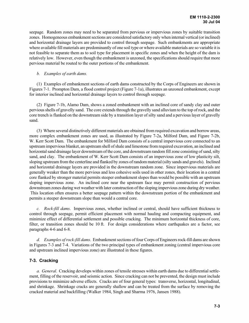
EM 1110-2-2300 30 Jul 04
7-3
seepage. Random zones may need to be separated from pervious or impervious zones by suitable transition zones. Homogeneous embankment sections are considered satisfactory only when internal vertical (or inclined) and horizontal drainage layers are provided to control through seepage. Such embankments are appropriate where available fill materials are predominantly of one soil type or where available materials are so variable it is not feasible to separate them as to soil type for placement in specific zones and when the height of the dam is relatively low. However, even though the embankment is unzoned, the specifications should require that more pervious material be routed to the outer portions of the embankment. b. Examples of earth dams. (1) Examples of embankment sections of earth dams constructed by the Corps of Engineers are shown in Figures 7-1. Prompton Dam, a flood control project (Figure 7-1a), illustrates an unzoned embankment, except for interior inclined and horizontal drainage layers to control through seepage. (2) Figure 7-1b, Alamo Dam, shows a zoned embankment with an inclined core of sandy clay and outer pervious shells of gravelly sand. The core extends through the gravelly sand alluvium to the top of rock, and the core trench is flanked on the downstream side by a transition layer of silty sand and a pervious layer of gravelly sand. (3) Where several distinctively different materials are obtained from required excavation and borrow areas, more complex embankment zones are used, as illustrated by Figure 7-2a, Milford Dam, and Figure 7-2b, W. Kerr Scott Dam. The embankment for Milford Dam consists of a central impervious core connected to an upstream impervious blanket, an upstream shell of shale and limestone from required excavation, an inclined and horizontal sand drainage layer downstream of the core, and downstream random fill zone consisting of sand, silty sand, and clay. The embankment of W. Kerr Scott Dam consists of an impervious zone of low plasticity silt, sloping upstream from the centerline and flanked by zones of random material (silty sands and gravels). Inclined and horizontal drainage layers are provided in the downstream random zone. Since impervious materials are generally weaker than the more pervious and less cohesive soils used in other zones, their location in a central core flanked by stronger material permits steeper embankment slopes than would be possible with an upstream sloping impervious zone. An inclined core near the upstream face may permit construction of pervious downstream zones during wet weather with later construction of the sloping impervious zone during dry weather. This location often ensures a better seepage pattern within the downstream portion of the embankment and permits a steeper downstream slope than would a central core. c. Rock-fill dams. Impervious zones, whether inclined or central, should have sufficient thickness to control through seepage, permit efficient placement with normal hauling and compacting equipment, and minimize effect of differential settlement and possible cracking. The minimum horizontal thickness of core, filter, or transition zones should be 10 ft. For design considerations where earthquakes are a factor, see paragraphs 4-6 and 6-8. d. Examples of rock-fill dams. Embankment sections of four Corps of Engineers rock-fill dams are shown in Figures 7-3 and 7-4. Variations of the two principal types of embankment zoning (central impervious core and upstream inclined impervious zone) are illustrated in these figures. 7-3. Cracking a. General. Cracking develops within zones of tensile stresses within earth dams due to differential settle-ment, filling of the reservoir, and seismic action. Since cracking can not be prevented, the design must include provisions to minimize adverse effects. Cracks are of four general types: transverse, horizontal, longitudinal, and shrinkage. Shrinkage cracks are generally shallow and can be treated from the surface by removing the cracked material and backfilling (Walker 1984, Singh and Sharma 1976, Jansen 1988).
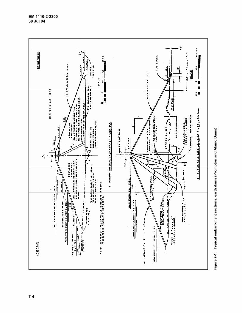
EM 1110-2-2300 30 Jul 04
7-4
Figu
re 7
-1.
Typ
ical
em
bank
men
t sec
tions
, ear
th d
ams
(Pro
mpt
on a
nd A
lam
o D
ams)
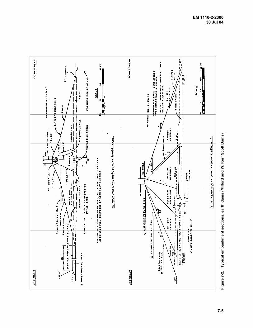
EM 1110-2-2300 30 Jul 04
7-5
Figu
re 7
-2.
Typ
ical
em
bank
men
t sec
tions
, ear
th d
ams
(Milf
ord
and
W. K
err S
cott
Dam
s)
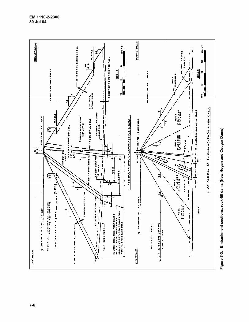
EM 1110-2-2300 30 Jul 04
7-6
Figu
re 7
-3.
Em
bank
men
t sec
tions
, roc
k-fil
l dam
s (N
ew H
ogan
and
Cou
gar D
ams)
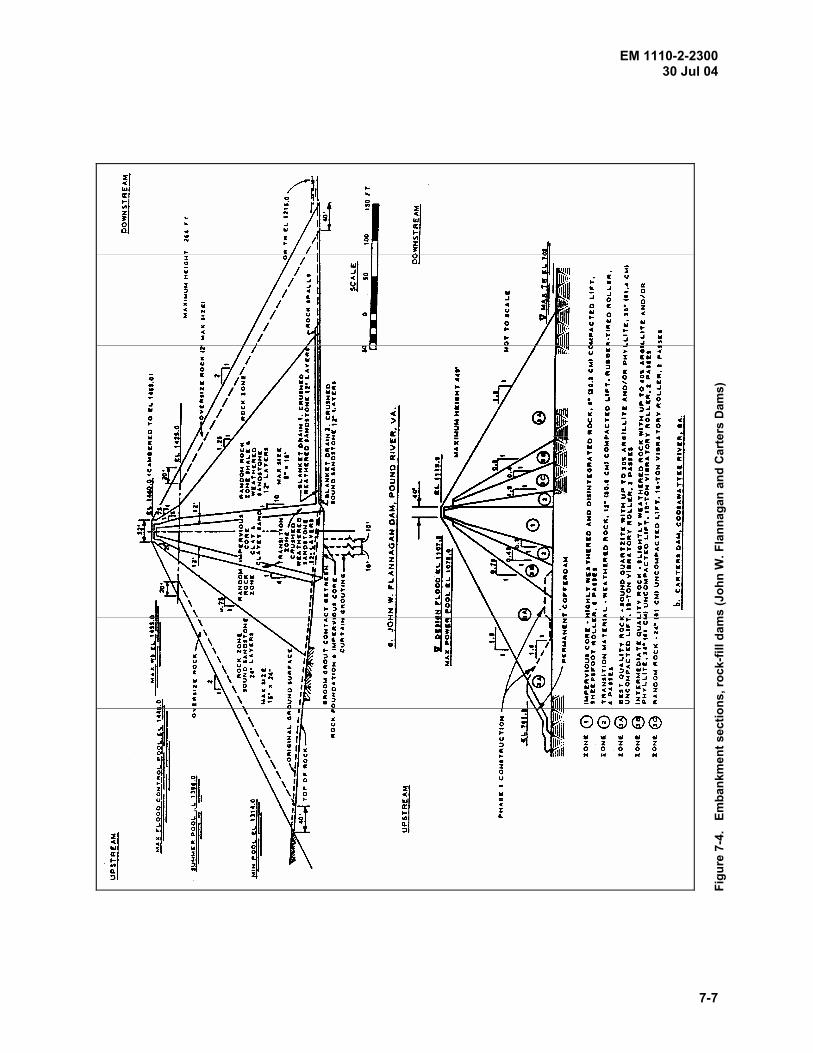
EM 1110-2-2300 30 Jul 04
7-7
Figu
re 7
-4.
Em
bank
men
t sec
tions
, roc
k-fil
l dam
s (J
ohn
W. F
lann
agan
and
Car
ters
Dam
s)

EM 1110-2-2300 30 Jul 04
7-8
b. Transverse cracking. Transverse cracking of the impervious core is of primary concern because it creates flow paths for concentrated seepage through the embankment. Transverse cracking may be caused by tensile stresses related to differential embankment and/or foundation settlement. Differential settlement may occur at steep abutments, at the junction of a closure section, at adjoining structures where compaction is difficult, or over old stream channels or meanders filled with compressible soils. c. Horizontal cracking. Horizontal cracking of the impervious core may occur when the core material is much more compressible than the adjacent transition or shell material so that the core material tends to arch across the less compressible adjacent zones resulting in a reduction of the vertical stress in the core. The lower portion of the core may separate out, resulting in a horizontal crack. Arching may also occur if the core rests on highly compressible foundation material. Horizontal cracking is not visible from the outside and may result in damage to the dam before it is detected. d. Longitudinal cracking. Longitudinal cracking may result from settlement of upstream transition zone or shell due to initial saturation by the reservoir or due to rapid drawdown. It may also be due to differential settle-ment in adjacent materials or seismic action. Longitudinal cracks do not provide continuous open seepage paths across the core of the dam, as do transverse and horizontal cracks, and therefore pose no threat with regard to piping through the embankment. However, longitudinal cracks may reduce the overall embankment stability leading to slope failure, particularly if the cracks fill with water. e. Defensive measures. The primary line of defense against a concentrated leak through the dam core is the downstream filter (filter design is covered in Appendix B). Since prevention of cracks cannot be ensured, an adequate downstream filter must be provided (Sherard 1984). Other design measures to reduce the susceptibility to cracking are of secondary importance. The susceptibility to cracking can be reduced by shaping the foundation and structural interfaces to reduce differential settlement, densely compacting the upstream shell to reduce settlement from saturation, compacting core materials at water contents sufficiently high so that stress-strain behavior is relative plastic, i.e., low deformation moduli, and shear strength, so that cracks cannot remain open (pore pressure and stability must be considered), and staged construction to lessen the effects of settlement of the foundation and the lower parts of the embankment. 7-4. Filter Design The filter design for the drainage layers and internal zoning of a dam is a critical part of the embankment design. It is essential that the individual particles in the foundation and embankment are held in place and do not move as a result of seepage forces. This is accomplished by ensuring that the zones of material meet “filter criteria” with respect to adjacent materials. The criteria for a filter design is presented in Appendix B. In a zoned embankment the coarseness between the fine and coarse zones may be such that an intermediate or transition section is required. Drainage layers should also meet these criteria to ensure free passage of water. All drainage or pervious zones should be well compacted. Where a large carrying capacity is required, a multilayer drain should be provided. Geotextiles (filter fabrics) should not be used in or on embankment dams. 7-5. Consolidation and Excess Porewater Pressures a. Foundations. (1) Foundation settlement should be considered in selecting a site since minimum foundation settlements are desirable. Overbuilding of the embankment and of the core is necessary to ensure a dependable freeboard. Stage construction or other measures may be required to dissipate high porewater pressures more rapidly. Wick drains should be considered except where installation would be detrimental to seepage characteristics of the structure and foundation. If a compressible foundation is encountered, consolidation tests should be performed on undisturbed samples to provide data from which settlement analyses can be made for use in comparing sites and

EM 1110-2-2300 30 Jul 04
7-9
for final design. Procedures for making settlement and bearing capacity analyses are given in EM 1110-1-1904 and EM 1110-1-1905, respectively. Instrumentation required for control purposes is discussed in Chapter 10. (2) The shear strength of a soil is affected by its consolidation characteristics. If a foundation consolidates slowly, relative to the rate of construction, a substantial portion of the applied load will be carried by the pore water, which has no shear strength, and the available shearing resistance is limited to the in situ shear strength as determined by undrained “Q” tests. Where the foundation shearing resistance is low, it may be necessary to flatten slopes, lengthen the time of construction, or accelerate consolidation by drainage layers or wick drains. Analyses of foundation porewater pressures are covered by Snyder (1968). Procedures for stability analyses are discussed in EM 1110-2-1902 and Edris (1992). (3) Although excess porewater pressures developed in pervious materials dissipate much more rapidly than those in impervious soils, their effect on stability is similar. Excess pore pressures may temporarily build up, especially under earthquake loadings, and effective stresses contributing to shearing resistance may be reduced to low values. In liquefaction of sand masses, the shearing resistance may temporarily drop to a fraction of its normal value. b. Embankments. Factors affecting development of excess porewater pressures in embankments during construction include placement water contents, weight of overlying fill, length of drainage path, rate of construction (including stoppages), characteristics of the core and other fill materials, and drainage features such as inclined and horizontal drainage layers, and pervious shells. Analyses of porewater pressures in embankments are presented by Clough and Snyder (1966). Spaced vertical sand drains within the embankment should not be used in lieu of continuous drainage layers because of the greater danger of clogging by fines during construction. 7-6. Embankment Slopes and Berms a. Stability. The stability of an embankment depends on the characteristics of foundation and fill materials and also on the geometry of the embankment section. Basic design considerations and procedures relating to embankment stability are discussed in detail in EM 1110-2-1902 and Edris (1992). b. Unrelated factors. Several factors not related to embankment stability influence selection of embankment slopes. Flatter upstream slopes may be used at elevations where pool elevations are frequent (usually +4 ft of conservation pool). In areas where mowing is required, the steepest slope should be 1 vertical on 3 horizontal to ensure the safety of maintenance personnel. Horizontal berms, once frequently used on the downstream slope, have been found undesirable because they tend to trap and concentrate runoff from upper slope surfaces. The water often cannot be disposed of adequately, whereupon it spills over the berm and erodes the lower slopes. A horizontal upstream berm at the base of the principal riprap protection has been found useful in placing and maintaining riprap. c. Waste berms. Where required excavation or borrow area stripping produces material unsuitable for use in the embankment, waste berms can be used for upstream slope protection, or to contribute to the stability of upstream and downstream embankment slopes. Care must be taken, however, not to block drainage in the downstream area by placing unsuitable material, which is often impervious, over natural drainage features. The waste berm must be stable against erosion or it will erode and expose the upstream slope. 7-7. Embankment Reinforcement The use of geosynthetics (geotextiles, geogrids, geonets, geomembranes, geocomposites, etc.) in civil engineering has been increasing since the 1970's. However, their use in dam construction or repairs, especially in the United States, has been limited (Roth and Schneider 1991; Giroud 1989a, 1989b; Giroud 1990, Giroud 1992a, 1992b). The Corps of Engineers pioneered the use of geotextiles to reinforce very soft foundation soils
EM 1110-2-2300 30 Jul 04
7-10
(Fowler and Koerner 1987, Napolitano 1991). The Huntington District of the Corps of Engineers used a welded wire fabric geogrid for reconstruction of Mohicanville Dike No. 2 (Fowler et al. 1986; Franks, Duncan, and Collins 1991). The Bureau of Reclamation has used geogrid reinforcement to steepen the upper portion of the downstream slope of Davis Creek Dam, Nebraska (Engemoen and Hensley 1989, Dewey 1989). 7-8. Compaction Requirements a. Impervious and semi-impervious fill. (l) General considerations. (a) The density, permeability, compressibility, and strength of impervious and semi-impervious fill materials are dependent upon water content at the time of compaction. Consequently, the design of an embankment is strongly influenced by the natural water content of borrow materials and by drying or wetting that may be practicable either before or after delivery to the fill. While natural water contents can be decreased to some extent, some borrow soils are so wet they cannot be used in an embankment unless slopes are flattened. However, water contents cannot be so high that hauling and compaction equipment cannot operate satisfactorily. The design and analysis of an embankment section require that shear strength and other engineering properties of fill material be determined at the densities and water contents that will be obtained during construction. In general, placement water contents for most projects will fall within the range of 2 percent dry to 3 percent wet of optimum water content as determined by the standard compaction test (EM 1110-2-1906). A narrower range will be required for soils having compaction curves with sharp peaks. (b) While use of water contents that are practically obtainable is a principal construction requirement, the effect of water content on engineering properties of a compacted fill is of paramount design interest. Soils that are compacted wet of optimum water content exhibit a somewhat plastic type of stress-strain behavior (in the sense that deformation moduli are relatively low and stress-strain curves are rounded) and may develop low “Q” strengths and high porewater pressures during construction. Alternatively, soils that are compacted dry of optimum water content exhibit a more rigid stress-strain behavior (high deformation moduli), develop high “Q” strengths and low porewater pressures during construction, and consolidate less than soils compacted wet of optimum water content. However, soils compacted substantially dry of optimum water content may undergo undesirable settlements upon saturation. Cracks in an embankment would tend to be shallower and more self-healing if compacting is on the wet side of optimum water content than if on the dry side. This results from the lower shear strength, which cannot support deep open cracks, and from lower deformation moduli. (c) Stability during construction is determined largely by “Q” strengths at compacted water contents and densities. Since “Q” strengths are a maximum for water contents dry of optimum and decrease with increasing water content, construction stability is determined (apart from foundation influences) by the water contents at which fill material is compacted. This is equivalent to saying that porewater pressures are a controlling factor on stability during construction. “Q” strengths, and pore-water pressures during construction are of more impor-tance for high dams than for low dams. (d) Stability during reservoir operating conditions is determined largely by “R” strengths for compacted material that has become saturated. Since “R” strengths are a maximum at about optimum water content, shear strengths for fill water contents both dry and wet of optimum must be established in determining the allowable range of placement water contents. In addition, the limiting water content on the dry side of optimum must be selected to avoid excessive settlement due to saturation. Preferably no settlement on saturation should occur. (2) Dams on weak, compressible foundations. Where dams are constructed on weak, compressible foundations, the embankment and foundation materials should have stress-strain characteristics as nearly similar as possible. Embankments can be made more plastic and will adjust more readily to settlements if they are com-pacted wet of the optimum water content. Differences in the stress-strain characteristics of the embankment and

EM 1110-2-2300 30 Jul 04
7-11
foundation may result in progressive failure. To prevent this from occurring, the embankment is designed so that neither the embankment nor the foundation will be strained beyond the peak strength so that the stage where progressive failure begins will not be reached. Strength reduction factors for the embankment and foundation are given in Figure 7-5 (Duncan and Buchignani 1975, Chirapuntu and Duncan 1976). (3) Dams on strong, incompressible foundations. Where the shear strength of the embankment is lower than that of the foundation, such as the case where there is a strong, relatively incompressible foundation, the strength of the fill controls the slope design. The “Q” strength of the fill will be increased by compacting it at water con-tents at or slightly below optimum water contents and the porewater pressures developed during construction will be reduced. Soils compacted slightly dry of optimum water content generally have higher permeability values and lower “R” strengths than those wet of optimum water content. Further, many soils will consolidate upon saturation if they are compacted dry of optimum water content. All of these factors must be considered in the selection of the range of allowable field compaction water contents. (4) Abutment areas. In abutment areas, large differential settlements may take place within the embankment if the abutment slopes are steep or contain discontinuities such as benches or vertical faces. This may induce tension zones and cracking in the upper part of the embankment. It may be necessary to compact soils wet of optimum water content in the upper portion of embankment to eliminate cracking due to differential settlements. Again, shear strength must be taken into account. (5) Field densities. Densities obtained from field compaction using conventional tamping or pneumatic rollers and the standard number of passes of lift thickness are about equal to or slightly less than maximum densities for the standard compaction test. This has established the practice of using a range of densities for performance of laboratory tests for design. Selection of design densities, while a matter of judgment, should be based on the results of test fills or past experience with similar soils and field compaction equipment. The usual assumption is that field densities will not exceed the maximum densities obtained from the standard compaction test nor be less than 95 percent of the maximum densities derived from this test. (6) Design water contents and densities. A basic concept for both earth and rock-fill dams is that of a core surrounded by strong shells providing stability. This concept is obvious for rock-fill dams and can be applied even to internally drained homogeneous dams. In the latter case, the core may be compacted at or wet of optimum while the outer zones are compacted dry of optimum. The selection of design ranges of water contents and densities requires judgment and experience to balance the interaction of the many factors involved. These include: (a) Borrow area water contents and the extent of drying or wetting that may be practicable. (b) The relative significance on embankment design of “Q” versus “R” strengths (i.e., construction versus operating conditions). (c) Climatic conditions. (d) The relative importance of foundation strength on stability. (e) The need to design for cracking and development of tension zones in the upper part of the embankment, especially in impervious zones. (f) Settlement of compacted materials on saturation. (g) The type and height of dam.
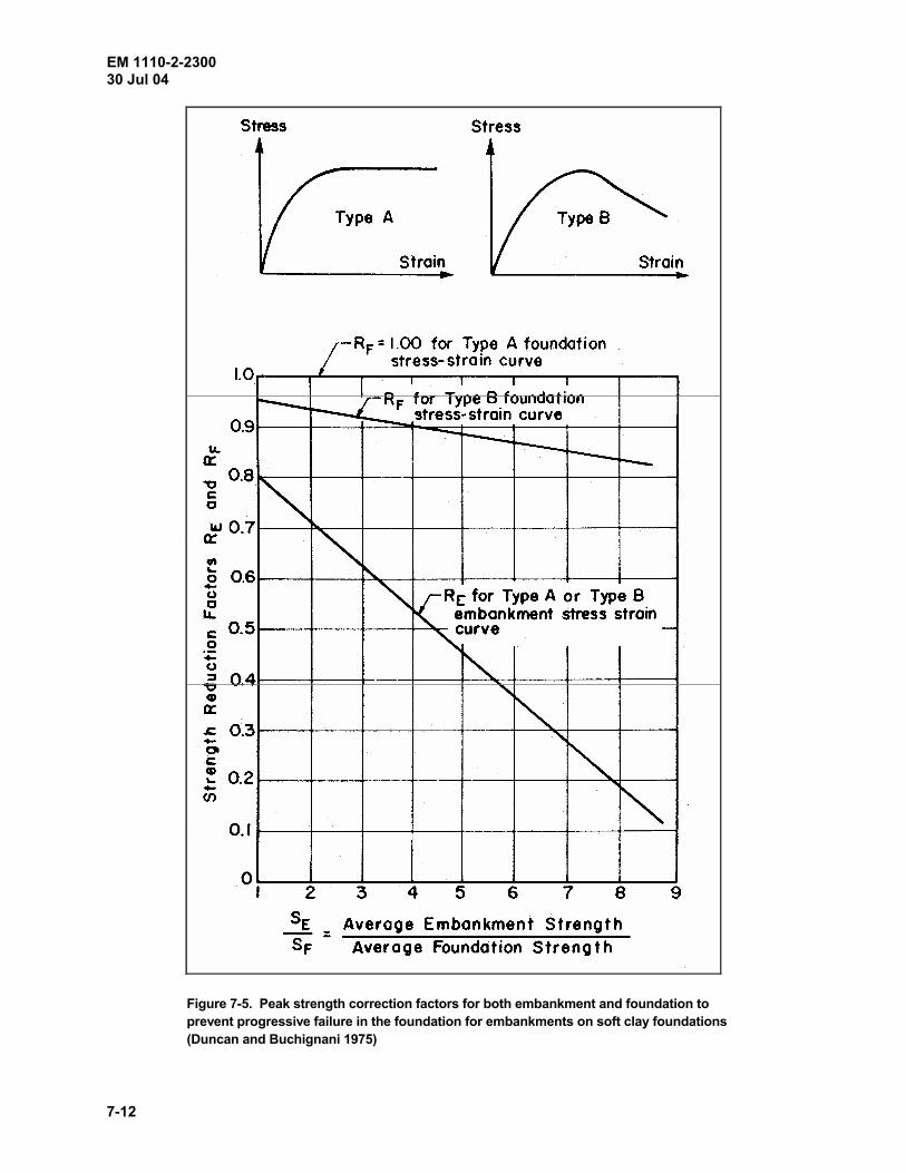
EM 1110-2-2300 30 Jul 04
7-12
Figure 7-5. Peak strength correction factors for both embankment and foundation to prevent progressive failure in the foundation for embankments on soft clay foundations (Duncan and Buchignani 1975)

EM 1110-2-2300 30 Jul 04
7-13
(h) The influence on construction cost of various ranges of design water contents and densities. (7) Field compaction. (a) While it is generally impracticable to consider possible differences between field and laboratory compaction when selecting design water contents and densities, such differences do exist and result in a different behavior from that predicted using procedures discussed in preceding paragraphs. Despite these limitations, the procedures described generally result in satisfactory embankments, but the designer must verify that this is true as early as possible during embankment construction. This can often be done by incorporating a test section within the embankment. When field test section investigations are performed, field compaction curves should be developed for the equipment used. (b) Proper compaction at the contact between the embankment and the abutments is important. Sloping the fill surface up on a 10 percent grade toward a steep abutment facilitates compaction where heavy equipment is to be used. Where compaction equipment cannot be used against an abutment, thin lifts tamped with hand-operated powered tampers should be used, but tamping of soil under overhangs in lieu of removal or backfilling with concrete should not be permitted. (c) Specific guidance on acceptable characteristics and operating procedures of tamping rollers, rubber-tired rollers, and vibratory rollers is given in guide specification UFGS-02330A, including dimensions, weights, and speed of rolling; also see EM 1110-2-1911. b. Pervious materials (excluding rock-fill). (l) The average in-place relative density of zones containing cohesionless soils should be at least 85 percent, and no portion of the fill should have a relative density less than 80 percent. This requirement applies to drainage and filter layers as well as to larger zones of pervious materials, but not to bedding layers beneath dumped riprap slope protection. The requirement also applies to filter layers and pervious backfill beneath and/or behind spillway structures. The relative density test is generally satisfactory for pervious materials containing only a few percent finer than the No. 200 sieve. For some materials, however, field compaction results equal to 100 percent or more of the standard compaction test maximum density can be readily obtained and may be higher than 85 percent relative density. If 98 percent of the maximum density from the standard compaction test is higher than 85 percent relative density, the standard compaction test should be used. The design should provide that clean, free-draining pervious materials be compacted in as nearly a saturated condition as possible. Otherwise compaction at bulking water contents might result in settlement upon saturation. (2) It is possible to place pervious fill such as free-draining gravel or fine to coarse sand, into a lift 3 to 4 ft thick in shallow water and to obtain good compaction by rolling the emerged surface of the lift with heavy crawler tractors. However, less pervious soils cannot be compacted if placed in this manner or even on a wet subgrade. In general, sand containing more than 8 to 10 percent finer than the No. 200 sieve cannot be placed satisfactorily underwater, and well graded sand-gravel mixtures must contain even fewer fines. The ability to place pervious soils in shallow water after stripping simplifies construction and makes it possible to construct cofferdams of pervious material by adding a temporary impervious blanket on the outer face and thus permit unwatering for the impervious cutoff section. The cofferdams subsequently become part of the pervious shells of the embankment. c. Rock-fill. (l) It is often desirable, especially where rocks are soft, for procedures to be used in compacting rock-fill materials to be selected on the basis of test fills, in which lift thicknesses, numbers of passes, and types of
EM 1110-2-2300 30 Jul 04
7-14
compaction equipment (i.e., different vibratory rollers) are investigated (paragraph 3-1k). Many test fills have been constructed by the Corps of Engineers and other agencies, and the results should be reviewed for possible applicability before constructing test fills. Rock-fill should not be placed in layers thicker than 24 in. unless the results of test fills show that adequate compaction can be obtained using thicker lifts. As the maximum particle size of rockfill decreases, the lift thickness should be decreased. In no case should the maximum particle size exceed 0.9 of the lift thickness. Smooth-wheeled vibratory rollers having static weights of 10 to 15 tons are effective in achieving high densities for hard durable rock if the speed, cycles per minute, amplitude, and number of passes are correct. Quarry-run rock having an excess of fines can be passed over a grizzly, and the fines placed next to the core. Fine rock zones should be placed in 12- to 18-in. lift thicknesses. (2) There is no need to scarify the surfaces of compacted lifts of hard rock-fill. Soft rocks, such as some sandstones and shales, often break down to fine materials on the surface of the lift. Other sandstones may be compacted in the same manner as other hard rocks. Scarifying has been used on soft sandstone layers to move fines down into the fill. If breaking down of the upper part of the layer cannot be prevented, it may be necessary to use very thin lifts to break the sandstone so that the larger particles are surrounded with sand. Ten-ton vibra-tory rollers and tracked equipment break the rock more than rubber-tired equipment. If soft material breaks down uniformly, vibratory or other equipment can be used, but the dam should be designed as an earth dam. Specifications should prohibit the practice often used by contractors of placing a cover of fine quarry waste on completed lifts of larger rock to facilitate hauling and to reduce tire wear. If such a cover of fines were extensive, it could have a detrimental effect on drainage and strength characteristics of the outer rock zones. 7-9. Slope Protection Adequate slope protection must be provided for all earth and rock-fill dams to protect against wind and wave erosion, weathering, ice damage, and potential damage from floating debris. Methods of protecting slopes include dumped riprap, precast and cast-in-place concrete pavements, soil cement, bituminous soil stabilization, sodding, and planting. The type of protection provided is governed by available materials and economics. Slope protection should be designed in accordance with the procedures presented in Appendix C. Due to the high cost, the initial slope protection design should be accomplished during the survey studies to establish a reliable cost estimate. The final design should be presented in the appropriate feature design memorandum.
EM 1110-2-2300 30 Jul 04
8-1
Chapter 8 Appurtenant Structures 8-1. Outlet Works a. Foundation. If the dam's foundation consists of compressible soils, the outlet works tower and conduit should be founded upon or in stronger abutment soils or rock where less settlement and horizontal spreading will occur and where the embankment is lower. Seepage collars should not be used because adequate compaction is rarely achieved around the collars and because their presence may increase the separation of conduit sections should the embankment tend to spread. A drainage layer should be provided around the conduit in the downstream zone of embankments. Excavation slopes in earth for conduits should be no steeper than 1 vertical on 2 horizontal to facilitate adequate compaction and bonding of backfill with the sides of the excavation. b. Concrete plug. A concrete plug should be used as backfill in rock cuts for cut-and-cover conduits within the core area to ensure a watertight bond between the structure and vertical rock surface. The plug, which can be constructed of lean concrete, should be provided over the length of the core contact area and extend up to the original rock surface. The substitution of hand-tamped earth fill is not considered an acceptable substitute for the lean concrete. Seepage collars should not be used except where they function for alignment control. In embank-ments having a random or an impervious downstream shell, horizontal drainage layers should be placed along the sides and over the top of conduits downstream of the impervious core. c. Basins. Intake structure towers and outlet headwalls at stilling basins are often recessed into the embankment to reduce the length of conduit. Since the tolerable horizontal movements of these features are very small, they should be designed for earth pressure at rest, taking into account the surcharge effect of the sloping embankment and water table considerations. Sidewalls should also be designed for at rest earth pressures, considering surface effects from the sloping embankment where applicable. d. Piers. When service bridge piers have been constructed concurrently with placement of the embank-ment fill, they have often suffered large horizontal movements. Construction of such piers should be delayed until after the embankment has been brought to grade, or at least until a large part of the embankment fill has been placed. e. Outlet structures. Where outlet structures are to be located in active seismic areas, special attention must be given to the possibility of movement along existing or possibly new faults. 8-2. Spillway a. Excavations. Excavations for spillways often require high side slopes cut into deposits of variable materials, often below groundwater table. If material from the spillway excavation is suitable for embankment fill, the stability of spillway slopes may be increased without increasing construction costs by excavating to flatter slopes. The stability of slopes excavated into natural materials is much more difficult to assess than that of slopes of properly constructed embankment. For excavation into natural soil deposits, detailed subsurface exploration including groundwater observations and appropriate laboratory tests on representative soils supply the information needed for slope stability analyses. When required excavation is in rock, the influence of structural discontinuities such as joints, faults, and bedding planes overshadows the properties of the intact rock as determined by tests on core samples. Consequently, detailed geologic studies and subsurface investigations, together with empirical data on natural and man-made slopes in the vicinity, are used for determining excavation slopes in rock and in clay shales.

EM 1110-2-2300 30 Jul 04
8-2
b. Grout curtains. It is often necessary to extend grout curtains beyond the dam axis to include the abut-ment between the dam and spillway, as well as beneath and across the spillway structure. If the rock is of poor quality, it may be necessary to build concrete walls or provide revetment to protect against erosion toward the spillway. 8-3. Other Important Considerations a. Temporary slopes. Temporary excavation slopes behind training walls are commonly shown on contract plans as 1 vertical on 1 horizontal for pay purposes; however, for major cuts and for cuts in weak materials, the slopes should be designed for adequate stability and the required slopes shown on the contract drawings. Drainage of the backfill must be provided to reduce pressures against the walls to a minimum. The backfill should either consist entirely of free-draining material or have a zone of free-draining material adjacent to the wall containing a collecting pipe drain along the lower part of the backfill near the wall. Where there is room to do so, the most effective way to control drainage within the soil backfill is an inclined drainage blanket with a longitudinal drain (see EM 1110-2-2502, paragraph 6-6). b. Channel slopes. Channel slopes adjacent to spillway and outlet structures must be designed to provide adequate factors of safety against slope failure. For some distance below stilling basins, the channel slopes and bed must be protected against scour with derrick stone and/or riprap; guidance on the design of such protection is furnished in EM 1110-2-1602 and EM 1110-2-1603. c. Embankments. Special attention must be given to the junction of embankments with concrete structures such as outlet works, spillway walls, lock walls, and powerhouses to avoid piping along the zone. An embankment abutting a high concrete wall creates a tension zone in the top of the embankment similar to that occurring next to steep abutments. Horizontal joints should not be chamfered in the contact areas between embankment and concrete. A 10 vertical on 1 horizontal batter on the concrete contact surfaces will ensure that the fill will be compressed against the wall as consolidation takes place. The interface of an earth embankment abutting a high concrete wall should be aligned at such an angle that the water load will force the embankment against the wall. The best juncture of a concrete dam with flanking earth embankments is by means of wraparounds. Internal drainage provided beneath the downstream portion of the embankment should be carried around to the downstream contact with the concrete structure. Compaction contiguous to walls may be improved by sloping the fill away from the wall to increase roller clearances. Where rollers cannot be used because of limited clearance or where specifications restrict the use of rollers near walls, power tamping of thinner layers should be used to obtain densities equal to the remainder of the embankment. It may be desirable to place material at higher water contents to ensure a more plastic material which can adjust without cracking, but then the effects of increased porewater pressures must be considered.

EM 1110-2-2300 30 Jul 04
9-1
Chapter 9 General Construction Considerations 9-1. General The design of an earth or rock-fill dam is a process continued until construction is completed. Much additional information on the characteristics of foundations and abutments is obtained during clearing, stripping, and trenching operations, which may confirm or contradict design assumptions based on earlier geologic studies and subsurface exploration by drill holes and test pits. Operations in the borrow areas and in required excavations also provide much data pertinent to characteristics of fill material and of excavated slopes. Weather and ground-water conditions during construction may significantly alter water contents of proposed fill material, or create seepage and/or hydraulic conditions, necessitating modifications in design. Projects must be continuously evalu-ated and “re-engineered,” as required, during construction, to ensure that the final design is compatible with conditions encountered during construction. Design and design review personnel will make construction site visits to determine whether design modifications are required to meet actual field conditions (see ER 1110-2-112). Environmental considerations discussed in paragraph 2-5 must be given attention in construction operations. 9-2. Obtaining Quality Construction a. Definitions (ER 1180-1-6). (1) Quality is conformance to properly developed requirements. In the case of construction contracts, these requirements are established by the contract specifications and drawings. (2) Quality management is all control and assurance activities instituted to achieve the product quality established by the contract requirements. (3) Contractor quality control (CQC) is the construction contractor's system to manage, control, and document his own, his supplier's, and his subcontractor's activities to comply with contract requirements.1 (4) Quality assurance (QA) is the procedure by which the Government fulfills its responsibility to be certain the CQC is functioning and the specified end product is realized. b. Policy. Obtaining quality construction is a combined responsibility of the construction contractor and the Government. The contract documents establish the level of quality required in the project to be constructed. In contracts of $1 million or greater, detailed CQC will be applied and a special CQC Section will be included in the contract. UFGS-01451A is to be used in preparation of the CQC Section. QA is required on all construction contracts. The extent of assurance is commensurate with the value and complexity of the contracts involved. QA testing is required (ER 1180-1-6). c. Contractor responsibility. Contractors shall be responsible for all activities necessary to manage, control, and document work so as to ensure compliance with the contract P&S. The contractor's responsibility includes ensuring adequate quality control services are provided for work accomplished by his organization, suppliers, subcontractors, technical laboratories, and consultants. For contracts of $1 million or greater, contractors will be required to prepare a quality control plan (ER 1180-1-6).
1 Additional information is given in EP 715-1-2 and International Commission on Large Dams Bulletin 56 “Quality Control for Fill Dams” (International Commission on Large Dams 1986).
EM 1110-2-2300 30 Jul 04
9-2
d. Government responsibility. QA is the process by which the Government ensures end product quality. This process starts well before construction and includes reviews of the P&S for biddability and constructibility, plan-in-hand site reviews, coordination with using agencies or local interests, establishment of performance periods and quality control requirements, field office planning, preparation of QA plans, reviews of quality control plans, enforcement of contract clauses, and acceptance of completed construction (ER 1180-1-6). e. QA for procedural specifications. Some QA testing in the case of earthwork embankment and concrete dam structures must be conducted continuously. A comprehensive QA testing program by the Government is necessary when specifications limit the contractor to prescriptive procedures leaving the responsibility for end product quality to the Government (ER 1180-1-6). 9-3. Stage Construction a. The term “stage construction” is limited here to construction of an embankment over a period of time with substantial intervals between stages, during which little or no fill is placed. Where a foundation is weak and compressible, or where impervious fill is on the wet side of normally acceptable placement water contents, it may be desirable to restrict the rate of fill placement or to cease fill placement for periods of time to permit excess pore-water pressures in the foundation and/or the fill to dissipate. Another beneficial effect of periods of inactivity is that rates of pore-pressure buildup in partially saturated soils upon resumption to fill placement may be reduced (see Clough and Snyder (1966) and Plate VIII-3 of EM 1110-2-1902). b. High embankments. Where high embankments are constructed in narrow valleys, it may be possible to place fill rapidly, which will increase pore-pressure buildup in the embankment and/or foundation. Rather than reduce the rate of fill placement unduly, it may be desirable to use flatter slopes, add stabilizing berms, or build the embankment in stages. 9-4. Stream Diversion a. Requirements. Requirements for diversion of streamflow during construction and the relative ease and cost of stream control measures may govern site selection. Since river diversion is a critical operation in constructing a dam, the method and time schedules for diversion are important elements of design. b. Methods of stream control. (1) The principal factors that determine methods of stream control are the hydrology of the stream, the topography and geology of the site, and the construction schedule. A common diversion method is to construct the permanent outlet works and a portion of the embankment adjacent to an abutment in the initial construction period. During the next construction period, at a time when flood possibility is low and favorable embankment placement conditions are likely, a cofferdam is constructed to divert riverflow through the outlet works (guidance on planning, design, and construction of cofferdams is given in ER 1110-2-8152 and EM 1110-2-2503). A downstream cofferdam may also be required until the embankment has been completed above tailwater elevation. In the period following diversion, the closure section is first brought up to a level with the remainder of the dam, after which the embankment is completed to a given height as rapidly as possible in preparation for high water. In the final period, the entire dam is brought up to full height. Simultaneous closure of upstream and downstream cofferdams may facilitate a difficult closure. The downstream cofferdam puts a back head on the construction area and reduces erosion of the downstream slope and adjacent foundation. (2) Cofferdams are often constructed in two stages: first, a small diversion cofferdam is constructed upstream of the main embankment, and second, the main cofferdam is constructed. The cofferdam may form a permanent part of the embankment wherever suitable strength and permeability characteristics of the fill can be obtained. Gravel fill is particularly suitable for cofferdam construction since it readily compacts under water. If
EM 1110-2-2300 30 Jul 04
9-3
seepage considerations require an upstream impervious blanket on a cofferdam built of pervious soil, the blanket should be removed later if it restricts drainage during drawdown. c. Cofferdam design. Major cofferdams are those cellular or embankment cofferdams, which, upon failure, would cause major damage downstream and/or considerable damage to the permanent work. Minor cofferdams are those which would result in only minor flooding of the construction work. All major cofferdams should be planned, designed, and constructed to the same level of engineering competency as for main dams. Design con-siderations should include minimum required top elevation, hydrologic records, hydrographic and topographic information, subsurface exploration, slope protection, seepage control, stability and settlement analyses, and sources of construction materials. The rate of construction and fill placement must be such to prevent over-topping during initial closure of the cofferdam. The cofferdam for Cerrillos Dam, Puerto Rico, was unique in that it was designed to handle being overtopped. The overtopping protection consisted of anchoring welded steel rebar/wire mesh to the downstream face. Crest protection was provided by gabions with asphalt paving (U.S. Army Engineer District, Jacksonville 1983). Minor cofferdams can be the responsibility of the contractor. Excavations for permanent structures should be made so as not to undermine the cofferdam foundation or other-wise lead to instability. Adequate space should be provided between the cofferdam and structural excavation to accommodate remedial work such as berms, toe buttresses, and foundation anchors should they be necessary. d. Protection of embankment. (1) Where hydrologic conditions require, emergency outlets should be provided to avoid possible overtopping of the incomplete embankment by floods that exceed the capacity of the outlet works. As the dam is raised, the probability of overtopping gradually decreases as a result of increased discharge capacity and reservoir storage. Should overtopping occur, however, damage to the partially completed structure and to downstream property increases with increased embankment heights. It is prudent to provide emergency outlets by leaving gaps or low areas in the concrete spillway or gate structure, or in the embankment during wintering over periods. Excavation of portions of the spillway approach and discharge channels, combined with maintaining low concrete weir sections, may provide protection for the later phases of embankment construction during which the potential damage is greatest. (2) When a portion of the embankment is constructed before diversion of the river, temporary riprap or other erosion protection may be required for the toe of the embankment adjacent to the channel. This temporary protection must be removed before placement of fill for the closure section. (3) In some cases the cost of providing sufficient flow capacity to avoid overtopping becomes excessive, and it is more appropriate to provide protection for possible overflow during high water conditions, as was done at Blakely Mountain Dam (U.S. Army Engineer Waterways Experiment Station 1956). (4) Within the past 10 years innovative methods for providing overtopping protection of embankments have been developed. These include roller-compacted concrete and articulated concrete blocks tied together by cables and anchored in place (see Hansen 1992; Powledge, Rhone, and Clopper 1991; Wooten, Powledge, and Whiteside 1992; and Powledge and Pravdivets 1992). 9-5. Closure Section a. Introduction. Because closure sections of earth dams are usually short in length and are rapidly brought to grade, two problems are inherent in their construction. First, the development of high excess porewater pressures in the foundation and/or embankment is accentuated, and second, transverse cracks may develop at the juncture of the closure section with the adjacent already constructed embankment as a result of differential settlement. When the construction schedule permits, excess porewater pressures in the embankment may be minimized by providing inclined drainage layers adjacent to the impervious core and by placing gently sloping

EM 1110-2-2300 30 Jul 04
9-4
drainage layers at vertical intervals within semi-impervious random zones. However, acceleration of foundation consolidation by means of sand blankets and vertical wick drains or reduction of embankment pore pressures by stage construction is generally impracticable in a closure section. A more suitable procedure is to use flatter slopes or stabilizing berms. Cracking because of differential settlement may be minimized by making the end slopes of previously completed embankment sections no steeper than 1 vertical on 4 horizontal. The soil on the end slopes of previously completed embankment sections should be cut back to well-compacted material that has not been affected by wetting, drying, or frost action. It may be desirable to place core material at higher water contents than elsewhere to ensure a more plastic material which can adjust without cracking, but the closure section design must then consider the effects of increased porewater pressures within the fill. The stability of temporary end slopes of embankment sections should be checked. b. Limit. If specifications limit the rate of fill placement, piezometers must be installed with tips in the foundation and in the embankment to monitor porewater pressures. Conduits should not be built in closure sec-tions or near enough to closure sections to be influenced by the induced loads. c. Closure section. Closure sections, with foundation cutoff trenches if required, are generally constructed in the dry, behind diversion cofferdams. In a few cases, the lower portions of rock-fill closure sections with “impervious” zones of cohesionless sands and gravels have been successfully constructed under water (see Pope 1960). Hydraulic aspects of river diversion and closures are presented in EM 1110-2-1602. 9-6. Construction/Design Interface It is essential that all of the construction personnel associated with an earth or rock-fill dam be familiar with the design criteria, performance requirements, and any special details of the project. As discussed in paragraph 4-7, coordination between design and construction is accomplished through the report on engineering considerations and instructions to field personnel, preconstruction orientation for construction engineers by the designers, and required visits to the site by the designers. 9-7. Visual Observations Visual observations during all phases of construction provide one of the most useful means for controlling construction and assessing validity of design assumptions. It is not practical, for economic reasons, to perform enough field density control tests, to install enough instrumentation, and to obtain enough data from pre-construction subsurface explorations to ensure that all troublesome conditions are detected and that satisfactory construction is being achieved. While test data and instrument observations provide more detailed and quanti-tative information than visual observations, they serve principally to strengthen and supplement visual observa-tions of the embankment and foundation as the various construction activities are going on. Field forces should be constantly on the alert for conditions not anticipated in the design, such as excessively soft areas in the foundation; jointing, faulting, and fracturing in rock foundations; unusual seepage; bulging and slumping of embankment slopes; excavation movements; cracks in slopes; and the like. It is particularly important to make observations during the first filling of the reservoir as weaknesses in a completed dam often show up at this time. For this reason, each reservoir project is required to have an “Initial Filling Plan” (discussed in paragraph 9-8). Visual observations of possible distress such as cracking, the appearance of turbid water in downstream toe drainage systems, erosion of riprap, soft wet spots downstream of the abutments or at the downstream toe or on the downstream slope, and other observations are important. Observations of instrumentation also yield valuable data in this respect. 9-8. Compaction Control a. Principal compaction. Principal compaction control is achieved by enforcement of specifications relat-ing to placement water content, lift thickness, compacting equipment, and number of passes for the various types

EM 1110-2-2300 30 Jul 04
9-5
of fill being placed. Experienced inspectors can quickly learn to distinguish visually whether the various contents are within the specified range for compaction, and to assess whether satisfactory compaction is being achieved. This ability is gained by closely observing the behavior of the materials during spreading and compacting operations. b. Field compaction. A systematic program of field compaction control should be established and executed, involving determinations of in-place densities and water contents, and relating the results to specified or desired limits of densities and water contents. Special emphasis must be placed in the compaction program on the need to obtain sufficient densities in each lift along the impervious core contact area on the abutments, and in each lift on either side of the outlet conduit along the backfill-conduit contact to verify adequate compaction in these and other critical zones. If good correlations can be obtained between direct methods and nuclear moisture-density meters, the latter may be used to increase the number of determinations with a minimum increase in time and effort, but nuclear measurements cannot be used to replace direct determinations. A more reliable method for determination of field water content is available using the microwave oven (see below). c. Oven system. A computer-controlled microwave oven system (CCMOS) is useful for rapid determination of water content for compaction control. The principle of operation of the system is that water content specimens are weighed continuously while being heated by microwave energy, and a computer monitors change in water content with time and terminates drying when all free water has been removed. A water content test in the CCMOS requires 10 to 15 min, and the system has been field tested at Yatesville Lake and Gallipolis Lock projects. Test results indicated that CCMOS produces water contents within 0.5 percent of conventional oven water content. Special procedures must be used when drying materials which burst from internal steam pressure during microwave drying (which includes some gravel particles and shales) and highly organic material, which requires a special drying cycle. Gypsum-rich soils are dehydrated by the microwave oven system giving erroneous results and should not be analyzed by this method. However, it should be noted that a special drying procedure is required to dry gypsum-rich soils in the conventional oven (Gilbert 1990, Gilbert 1991). d. Compaction. In order to check the adequacy of compaction in the various embankment zones and to confirm the validity of the design shear strengths and other engineering parameters, a systematic schedule for obtaining 1-cu-ft test pit samples at various elevations and locations in the embankment should be established. Samples so obtained will be suitably packed and shipped to division laboratories for performance of appropriate tests. 9-9. Initial Reservoir Filling a. General. The initial reservoir filling is defined as a deliberate impoundment to meet project purposes and is a continuing process as successively higher pools are attained for flood control projects. The initial reservoir filling is the first test of the dam to perform the function for which it was designed. In order to monitor this performance, the rate of filling should be controlled to the extent feasible, to allow as much time as needed for a predetermined surveillance program including the observation and analysis of instrumentation data (Duscha and Jansen 1988). A design memorandum (DM) on initial reservoir filling is required for all new reservoir projects.1 b. Design memorandum. As a minimum, the DM on initial reservoir filling will include the following (EM 1110-2-3600): (1) Reservoir regulations during project construction stage(s). (2) Water control plan. 1 Additional information is given in ETL 1110-2-231.
EM 1110-2-2300 30 Jul 04
9-6
(3) Project surveillance. (4) Cultural site surveillance. (5) Flood emergency plan. (6) Public affairs. (7) Safety plan. (8) Transportation and communications. 9-10. Construction Records and Reports a. General. Engineering data relating to project structures will be collected and permanently retained at the project site (see Appendix A of ER 1110-2-100). This information has many uses such as determining the validity of claims made by construction contractors, designing future alterations and additions to the structure, familiarizing new personnel with the project, and providing guidance for designing comparable future projects. These documents will include as many detailed photographs as necessary. Construction documentation also provides the basis for analysis and remedial action in the event of future distress, and therefore, certain information must be available for reference throughout the operating life of the project. Close coordination with those responsible for dam safety evaluations is necessary to determine which information should be kept in active files and which information can be archived. Consideration must also be given to the security of design and construction information to assure that access is prohibited to individuals and organizations that are potential threats to Corps of Engineer water resource infrastructure. b. Field control data. Records including field control data on methods of compaction, in-place unit weight and moisture content, piezometers, surface monuments, and inclinometers are kept for use in construction, opera-tion, and maintenance of the project. Instructions regarding specific forms to use for field data control are given in ER 1110-2-1925. c. As-constructed drawings. As construction of a project progresses, plans will be prepared showing the work as actually constructed. Changes may be indicated in ink on prints of the construction drawings or the trac-ings may be revised and new prints made to show the work as constructed, as specified in ER 1110-2-1200. d. Embankment criteria and foundation report. Earth and earth-rock-fill dams require an embankment criteria and foundation report to provide a summary of significant design assumptions and computations, specifi-cation requirements, construction procedures, field control and record control test data, and embankment perfor-mance as monitored by instrumentation during construction and during initial reservoir filling. This report is usually written by persons with first-hand knowledge of the project design and construction. The written text is brief with the main presentation consisting of a set of identified construction photographs, data summary tables, and as-constructed drawings. This report provides in one volume the significant information needed by engineers to familiarize themselves with the project and to reevaluate the embankment in the event unsatisfactory performance occurs (see ER 1110-2-1901). e. Construction foundation report. In addition to an embankment criteria and foundation report, all major and unique dams require a construction foundation report to be completed within 6 months after completion of the project or part of the project for which the report is written (see Appendix A of ER 1110-1-1901 for a sug-gested outline for foundation reports). This report documents observations of subsurface conditions encountered in all excavations and provides the most complete record of subsurface conditions and treatment of the foundation. The foundation report should be complete with such details as dip and strike of rock, faults, artisan conditions, and other characteristics of foundation materials. A complete history of the project in narrative form

EM 1110-2-2300 30 Jul 04
9-7
should be written, giving the schedule of starting and completing the various phases of the work, describing construction methods and equipment, summarizing quantities of materials involved, and other pertinent data. An accurate record should be maintained as to the extent and removal of all temporary riprap or stockpiled rock such as that used for diversion channel protection. The construction foundation report saves valuable time by eliminating the need to search through voluminous construction records of the dam to find needed information to use in planning remedial action should failure or partial failure of a structure occur as a result of foundation deficiencies. f. Photographs and video tape taken during construction. Embankment criteria and foundation and con-struction foundation reports should be supplemented by photographs that clearly depict conditions existing during embankment and foundation construction. Routine photographs should be taken at regular intervals, and additional pictures should be taken of items of specific interest, such as the preparation of foundations and dam abutments. For these items, color photographs should be taken. The captions of all photographs should contain the name of the project, the date on which the photograph was taken, the identity of the feature being photographed, and the location of the camera. In reports containing a number of photographs, an alternative would be an index map with a circle indicating the location of the camera with an arrow pointing in the direction the camera was pointing, with each location keyed to the numbers on the accompanying photographs (EM 1110-2-1911). Consideration should be given to using video tape where possible to document construction of the dam. Precautions must be taken to secure electronic digital images and/or to control access to such files to prohibit the alteration of the information that has been captured.

EM 1110-2-2300 30 Jul 04
10-1
Chapter 10 Instrumentation 10-1. General a. Introduction. All Corps of Engineers embankment dams should have an adequate level of instrumen-tation to enable design engineers to monitor and evaluate the safe performance of the structures during the construction period and under all operating conditions. This includes all appurtenant structures and facilities whose failure or malfunction would cause or contribute to loss of life, severe property damage, or loss of function or interruption of authorized mission. Instrumentation is not a substitute for an inadequate design. It is a tool to monitor and verify the performance of the design as constructed. The responsible district command should ensure the following:
(1) An appropriate level of instrumentation exists at each project. (2) Adequate maintenance is programmed and accomplished.
(3) A sufficient level of effort and funding is devoted to the program.
(4) A timely reduction, interpretation, and evaluation of the data occur.
(5) This information is incorporated into a project performance evaluation.
(6) Monitoring results are permanently documented and made available for appropriate action.
The information that follows is described for embankment dams and levees. Similar concepts can and should be used on appurtenant structural features that are critical to project performance such as spillways, intake towers, walls, and control bridges. b. Dam safety. In view of concerns for dam safety, it has become increasingly important to provide sufficient instrumentation in earth and rock-fill dams for monitoring the performance of the structure during construction, and for all anticipated stress conditions throughout the operational life of the project. Visual observations and the interpretation of instrumentation data from the embankment, foundations, abutments, and appurtenant features provide the primary means for engineers to evaluate dam safety. In recent years, technology of devices for measuring seepage, stresses, and movements in dams has improved significantly with respect to accuracy, reliability, and economics. These technologies should be used to the extent necessary to acquire sufficient information within the required timeframe to assure the thorough understanding of dam performance. Guidance on the selection and use of various types of instrumentation is presented in EM 1100-2-1908, Parts 1 and 2. 10-2. Instrumentation Plan and Records a. General. The planning, design, and layout of an instrumentation program are integral parts of the project design. Instrument data are an extremely valuable asset that supplies an insight into the actual behavior of the structure relative to design intent for all operating conditions, establishes performance that is uniquely characteristic to the dam, and provides a basis for predicting future behavior. As structures age and new design criteria are developed, the historical data provide most of the information necessary to evaluate the safety of the structure with respect to current standards and criteria. Older structures may require additional instrumentation to gain a satisfactory level of confidence in assessing safe performance. Instrument data can be of benefit only if the instruments consistently function reliably and the data values are compared

EM 1110-2-2300 30 Jul 04
10-2
to the documented design limits and historical behavior. Automation of dam safety instrumentation is a proven, reliable approach to obtaining instrument data and other related condition information. Automation offers a feasible alternative to obtaining routine data that may not otherwise be obtained because of funding constraints, staff reductions, or inaccessibility. Automation can also be helpful with investigating and analyzing performance conditions that require frequent, timely, and accurate information that cannot be feasibly collected manually. It is recognized that automation technology evolves rapidly, and this specialized expertise is not resident at all districts. Assistance with automation is available through The Corps of Engineers Center for Automated Performance Monitoring of Dams, reference ER 1110-1-8158. b. System design. The design and construction of new projects as well as the rehabilitation, dam safety modifications, and normal maintenance of older projects present opportunities to prepare for the future engineering analyses of structural performance. Careful attention and detail should be incorporated into the planning of instrumentation systems and programs to ensure that the required information is obtained. As a minimum, the parameters that are critical to satisfactory performance (see Appendix E) will dictate the selection of instrument types. Ideally, instrument systems will include some degree of overlap and/or redundancy to enable verification of problems that may be detected. Appropriate instrument devices are selected to provide the engineering measurements to the magnitude, precision, and response time necessary to evaluate the parameters. Generally, the types of measurements are as follows:
(1) Horizontal and vertical movement.
(2) Alignment and tilt.
(3) Stresses and strains in soil and rock fill.
(4) Pore pressure.
(5) Uplift pressure.
(6) Phreatic surfaces.
(7) Seepage clarity and quantity. In all circumstances, background information that may affect the validity of the data or the analysis of the performance (such as hydrologic or weather conditions) is documented and baseline instrument data for each type of measurement is obtained for future comparison. Other considerations include the potential damage resulting from construction or vandalism, effects of a severe environment on the instruments, and maintenance and personnel requirements for data collection and evaluation. c. Installation and maintenance. Instrumentation for a project should be included in the design phase, during construction, and throughout the operational life of the project as conditions warrant. After a project has been operational for several years, appropriate maintenance, repair, and replacement of instrumentation must be accomplished during the normal operation to assure continued data acquisition and analyses of critical performance parameters. Specific guidance for maintenance, rehabilitation, and replacement can be found in EM 1110-2-1908. Note that specialized expertise may be required to install and maintain automated instrumentation. d. Data collection, interpretation, and evaluation. The frequency with which instrumentation data are obtained must be tailored to the monitoring purpose, period of construction, investigation, or other interest, and project operating conditions. In all cases, sufficient calibration must be performed and background data must be obtained to ensure that a valid and reliable database is developed, maintained, and available to facilitate subsequent comparisons. After a baseline of performance is established, the subsequent reading of

EM 1110-2-2300 30 Jul 04
10-3
instruments during construction and operating conditions should be based on an anticipated rate of loading or changes in reservoir levels. The timely reduction and interpretation of instrumentation data are essential for a responsive safety evaluation of the project. For all Corps projects, this reduction, interpretation, and evaluation should occur as soon as conditions warrant after the data were obtained. The evaluation of the data should follow immediately. As a minimum, all data should be plotted as instrument response with respect to time, as well as reservoir level or other range of loading. More detailed guidance for data acquisition, interpretation, evaluation, and presentation is in EM 1110-2-1908.
e. Documentation. Information relative to instrumentation systems is an invaluable resource that is necessary to evaluate instrument and system performance, as well as influence the assessment of dam performance and should be preserved and readily accessible. Such information includes, but is not limited to, installation reports, testing results, modification to the sensors or system components, maintenance records, manufacturers performance specifications, warrantees, and other information.
10-3. Types of Instrumentation The type, number, and location of required instrumentation depend on the layout of the project and the construction techniques employed. Devices may consist of the following: piezometers (open tube, such as the Casagrande type, electrical, vibrating wire, or occasionally closed systems) located in the foundation abutment and/or embankment, surface monuments, settlement plates within the embankment, inclinometers, movement indicators (at conduit joints, outlet works, and intake tower), internal vertical and horizontal movement and strain indicators, earth pressure cells, and accelerographs (in areas of seismic activity). 10-4. Discussion of Devices a. Piezometers. The safety of a dam is affected by hydrostatic pressures that develop in the embankment, foundation, and abutments. Periodic piezometer observations furnish data on porewater pressures within the embankment, foundation, and abutments, which indicate the characteristics of seepage conditions, effectiveness of seepage cutoff, and the performance of the drainage system. The installation should consist of several groups of piezometers placed in vertical planes perpendicular to the axis of the dam so that porewater pressures and/or seepage pressures may be accurately determined for several cross sections. At each cross section that piezometers are placed, some should extend into the foundation and abutments and be located at intervals between the upstream toe and the downstream toe, as well as being placed at selected depths in the embankment. In addition to the groups of piezometers at selected cross sections, occasional piezometers at intermediate stations will provide a check on the uniformity of conditions between sections. Each piezometer should be placed with its tip in pervious material. If pervious material is not present in the natural deposit of foundation material, or if the tip is in an impervious zone of the embankment, a pocket of pervious material should be provided. Two of the more important items in piezometer installation are the provision of a proper seal above the screen tip and the water tightness of the joints and connections of the riser pipe or leads. b. Surface monuments. Permanent surface monuments to measure both vertical and horizontal alignment should be placed in the crest of the dam and on the upstream and downstream slopes. Survey control should be maintained from offsite reference monuments located in stable material outside of the limits of influence from the construction and removed from the parameters being monitored. Monuments should be embedded in the embankment by means of a brass or steel rod encased in concrete to a depth regionally appropriate to avoid frost action. All monuments must be protected against disturbance by construction and maintenance equipment. Guidance on spacing is as follows: 50-ft intervals for crest lengths up to 500 ft, l00-ft intervals for crest lengths to 1,000 ft, and 200- to 400-ft intervals for longer embankments. These monuments should be installed as early as possible during construction and readings obtained on a regular basis. c. Inclinometers. Inclinometers should be installed in one or more cross sections of high dams, dams on weak deformable foundations, and dams composed at least in part of relatively wet, fine-grained soils. Inclino-
EM 1110-2-2300 30 Jul 04
10-4
meters should be installed particularly where dams are located in deep and narrow valleys where embankment movements are both parallel and perpendicular to the dam axis. Inclinometers should span the suspected zone of concern. It is essential that these devices be installed and observed during construction as well as during the operational life of the project. d. Miscellaneous movement indicators. Various types of instrumentation may be installed to measure horizontal spreading of the embankment (particularly when the foundation is compressible), movements adjacent to buried structures, foundation settlement, and internal strains. Strain measurements are particularly significant adjacent to abutments and below the crest to detect cracking of the core. Where there is a possibility of axial extension, as near steep abutments, surface monuments should be placed on the crest at 50-ft intervals to permit measurement of deformations along the axis. e. Pressure cells. The need for reliable pressure cells for measuring earth pressures in embankments has long been recognized, and much research has been done toward their development. Although many pressure cells now installed in earth dams have not proved to be entirely satisfactory, newer types are proving to be satisfactory and increased usage is recommended. Some types of pressure cells installed at the interface of concrete structures and earth fill have performed very well. f. Accelerographs. For important structures in areas of seismic activity, it is desirable to install strong-motion, self-triggering recording accelerographs to record the response of the dam to the earthquake motion. ER 1110-2-103 provides requirements and guidance for installation and servicing of strong-motion instruments. EM 1110-2-1908 discusses types of devices and factors controlling their location and use. Digital accelerographs are recommended as replacements for existing analog film-type accelerographs. The digital units record and provide fundamental event information on a near real-time basis and should be incorporated into dam safety monitoring programs. A status report on Corps of Engineers strong-motion instrumentation for measurement of earthquake motions on civil works structures is provided annually. The monitoring of seismic activity at Corps dams is shared by ERDC, Vicksburg, MS, and the U.S. Geological Survey, depending on the geographic location of the dam. Dam Safety engineers should establish and maintain close coordination with the appropriate organization for seismic monitoring. 10-5. Measurements of Seepage Quantities The seepage flow through and under a dam produces both surface and subsurface flow downstream from the dam. The portion of the total seepage that emerges from the ground, or is discharged from drains in the dam, its foundation, or abutments, is the only part that can be measured directly. An estimate of the quantity of subsurface flow from flow net studies may be based on assumed values of permeability. The portion of the seepage that appears at the ground surface may be collected by ditches or pipe drains and measured by means of weirs or other devices (monitoring performance of seepage control measures is discussed in detail in Chapter 13 of EM 1110-2-1901). 10-6. Automated Data Acquisition Systems a. General. Developments in the field of electronics have now made it possible to install and operate automated instrumentation systems that provide cost-effective real-time data collection from earth and rockfill dams. Installation of these computer-based automated data acquisition systems (ADAS) provides for more accurate and timely acquisition, reduction, processing, and presentation of instrumentation data for review and evaluation by geotechnical engineers. Consideration should be given to providing an ADAS for all new dam projects, dam safety modifications to existing dams, and monitoring system rehabilitation that are necessary to assure appropriate data acquisition. General guidance for developing an ADAS is presented in Appendix D.

EM 1110-2-2300 30 Jul 04
10-5
b. Conditions warranting automated data acquisition systems. The following are examples of conditions that would benefit from the use of an ADAS:
(1) The project is located in a remote area, or would be inaccessible during critical operating conditions. (2) Limited staffing is required to perform other duties when extreme loading conditions exist, such as flood fighting or emergency response, and is not available for monitoring requirements. (3) High frequency of data collection is necessary to help define complex or interrelated conditions. (4) Rapid or immediate dam performance assessments are required.