Embed Size (px)
Citation preview
Accepted Manuscript
Design and characteristics evaluation of a novel spherical underwaterrobot
Yaxin Li, Shuxiang Guo, Yu Wang
PII: S0921-8890(16)30254-8DOI: http://dx.doi.org/10.1016/j.robot.2017.03.014Reference: ROBOT 2813
To appear in: Robotics and Autonomous Systems
Received date : 18 May 2016
Please cite this article as: Y. Li, et al., Design and characteristics evaluation of a novel sphericalunderwater robot, Robotics and Autonomous Systems (2017),http://dx.doi.org/10.1016/j.robot.2017.03.014
This is a PDF file of an unedited manuscript that has been accepted for publication. As a service toour customers we are providing this early version of the manuscript. The manuscript will undergocopyediting, typesetting, and review of the resulting proof before it is published in its final form.Please note that during the production process errors may be discovered which could affect thecontent, and all legal disclaimers that apply to the journal pertain.
Design and Characteristics Evaluation of a Novel Spherical Underwater Robot
Yaxin Li*1 · Shuxiang Guo*3,*4 · Yu Wang*1, *2
Abstract This paper depicts the structural design of a novel water-jet-based spherical underwater robot. The propulsion system is
made up of four water-jet thrusters and 8 steering servo motors which can adjust the polydirectional shift of thrusters nozzle to
achieve 4-degrees-of-freedom (4-DOF) motion. Every two thrusters nozzles formed an angle of 90 degree in one plane. A bilayer
structure was adopted for the control system to obtain data from various sensors, meanwhile control the outputs of ports after
calculation processing. The primary side whose core is TMS320f28335 processor was employed for the data collection and
disposing calculation. And made the Atmega2560 processor as the main chip of the subordinate side to control the propulsion
system. The Micron Data Modem is integrated into the electrical design, which can realize the data transmission and
communication between multi-SURs in future. Based on the theoretical analysis and calculation, a series of underwater
experiments were carried out to test the performance of the novel spherical underwater robot; these experiments included surge-
sway motion test, yaw motion test, heave motion test, and anti-interference test. A FSMC controller was employed to control the
direction of the vectored water-jet thrusters for underwater motion. The experimental results demonstrated that the novel
spherical underwater robot could realize underwater motion rapidly and accurately. The performance of the novel SUR is more
nimbler and flexible than the previous SUR-II we developed.
Keywords Novel spherical underwater robot; Vectored water-jet thrusters propulsion system; Micron Data Modem; Electrical
design; Underwater experiments.
Yaxin Li
*Corresponding author
*1. School of Electrical Engineering and Information, Southwest Petroleum University, No.8 Xindu Avenue, Xindu District,
610500, Chengdu city, Sichuan, China
Tel:+86-17381545140
E-mail: [email protected]
Shuxiang Guo
*3.Key Laboratory of Convergence Medical Engineering System and Healthcare Technology, The Institute of Advanced Medical
Engineering System, School of Life Science, Beijing Institute of Technology, Beijing, China
*4.Faculty of Engineering, Kagawa University, Takamatsu, Kagawa 760-8521, Japan
Yu Wang
*Corresponding author
*1. School of Electrical Engineering and Information, Southwest Petroleum University, No.8 Xindu Avenue, Xindu District,
610500, Chengdu city, Sichuan, China
*2. Graduate School of Engineering, Kagawa University, Takamatsu, Kagawa, Japan
Tel:+86-17381545590
E-mail: [email protected]

1. Introduction
Underwater environment and underwater creature is mysterious. With the booming development of ocean scientific exploitation,
researchers are eager to realize more and more underwater interventions. Therefore, unmanned underwater vehicles (UUVs) are
developed rapidly due to their ability to access deep, dangerous, and confined areas unattainable by divers. Underwater robots
show significant potential of being applied in the fields of industry, fishery, exploration, and military and so on. Underwater robots
have become one of the most important tools to exploit and use marine resources [1]-[4]. An Autonomous Underwater Vehicle
(AUV) is an unmanned untethered underwater vehicle that carries its own power source and relies on an on-board computer and
built-in machine intelligence to execute a mission consisting of a series of preprogrammed instructions modifiable on-line by data
or information gathered by the vehicle sensors [5]. Different applications or tasks require different configurations, shapes, and sizes
of AUVs. For example, manipulators are necessary for mine-clearing operations and some other environmental tasks. If a robot is
used for underwater environmental detection or observation, a smaller and more flexible design enables the robot to work in
smaller spaces. If high-speed cruising is required, then a streamlined robot body is essential [6]. Nonlinear dynamic behavior and
unpredictable underwater environment make it difficult to control the underwater robot, especially if the robot is developed for
some complex missions. To meet the demanding control requirements, many control architectures have been developed, for
instance, the hierarchical architecture, the heterarchical architecture, the subsumption architecture, and the hybrid architecture [7].
1.1 The previous research
The spherical underwater robot (SUR) as a member of the new type of spherical robots has made its debut in recent years. It
consists of a ball-shaped outer shell to accommodate the whole mechanism inclusive of control devices and energy sources [8].
Due to the central symmetry, spherical objects always performance high stability and flexibility, spherical robots can perform a
rotational motion with a 0 � turn radius. Many types of SUR have been developed. ODIN-III was a typical prototype robot
developed at the University of Hawaii [9][10]. The metal hull with a diameter of 630 mm resisted water pressure. The propulsion
system with 8 screw propellers installed outside the body provided propulsive forces. This spherical underwater robot was used to
monitor the environment and underwater operations. University of Manchester and Oxford University co-developed a micro-
spherical underwater robot to monitor nuclear storage ponds [11]-[14]. The micro robot installed six propellers around the equator
as its propulsion system. The diameter of this robot was only 150mm. This micro-robot was developed to monitor nuclear storage
ponds and wastewater treatment facilities to prevent leakage. Besides propeller, tunnel thrusters are also favored by the researchers
who have high requirements on the propeller. Du et al. developed a spherical underwater robot with water-jet thrusters [15][16].
Lan et al. at the Beijing University of Post and Telecommunications developed a spherical underwater robot that is only actuated
by one tunnel propeller [17]. Based on a movable weight-balancing block, the attitude control was realized.
1.2 Motivation
Contrast to the kinds of the underwater robots proposed above, we considered plenarily all the merits and drawbacks of these
robots’ features, and summarized that our new generation underwater robot should have these characteristics as follows:
High-maneuverability;
Low-noise;
Multiple DOF;
Short turning radius;
Flexible and simple mechanism;

Easy to be controlled;
High cruising and standby ability.
Summing up the above requirements, we proposed a novel spherical underwater robot, which is named as SUR-III. The
propulsion system of the SUR-III is composed of four water-jet thrusters and 8 steering motors. The prototype and body
coordinate system is illustrated in Fig. 1. The robot is seized of a sphere hull whose diameter is 410 mm. The propulsion system
consisted of four vectored water-jet thrusters, and every two thruster nozzles form an angle of 90 degree in equatorial plane,
which is different from other traditional distribution structure.
(a) Side view (b) Top view
Fig. 1 Prototype of the novel spherical underwater robot (SUR-III)
1.3 Organization of the paper
The two main research works of this paper are as follows: First, we carried mechanical design on the novel vectored water-jet
propulsion spherical underwater robots, and we also carried electrical design on the inner control circuit of the SUR-III, so it will
be clearly on the overall framework and working principle of the SUR-III. And we also discussed the design and distribution of the
propulsion system in details. This part will be proposed in section 2. The details of electrical design are presented in section 3.
Secondly, based on the developed prototype, we carried out groups proof experiments to verify the performance of the SUR-III.
The results are described in section 4. And Section 5 depicts the conclusions and future works.
2. Mechanical design
2.1 Structure of the SUR-III
The structural design of the robot was symmetric about the three axis.The diameter of the SUR-III (D) was 410 mm, and its
weight in air was 7.6 - 7.9 kg. There were two important aspects of the design that should be noted. Firstly, the robot was not
bottom-heavy; the weight of the inside components was distributed. The waterproof bin (containing the batteries, control boards,
and other electronic components) was suspended from the top of the shell by four 140-mm-long screws, while the thrusters were
fixed on the annular support frame around waterproof bin. And the annular support frame is fastened on the waterproof bin by the
push force provided by screws, meanwhile, the four clamping screws can fix the servo motor on the annular support frame, that
means to achieve two things at one stroke. This artful structure is shown in Fig.2. Secondly, the vertical direction position of the
waterproof bin could be adjusted by four long screws. Hence, the center of mass of the robot was adjustable. The detailed
illustration of the robot is illustrated in Fig. 3.

(a) Fix the servo motor on the annular support frame (b) Fasten the support frame on the waterproof bin
Fig. 2 Connection structure of the propulsion system
As is shown in Fig.3, SUR-III was protected by an acrylic spherical hull with four holes for thruster nozzles. The hull is
consisted of two hemispheres, whose size are 410mm in diameter and 3.3mm in thickness. It is well known that arches and spheres
are ideal structures for pressure resistance. In this case, even though there were holes on the hull, adequate pressure resistance will
be provided to the robot. The waterproof bin was sealed by a cover and 8 short screws. The most distinctive structure is applied in
the propulsion system. The particular distribution of the four thrusters made our robot easily to be controlled, meanwhiles boost up
the motility and sensibility. With these features, SUR-III can realize some very difficult motions which can not be finished by
SUR-II. On the other hand, the SUR-III can finish the same motion with less time, the reason will be explained by experiment
results in section 4.
Fig.3 Overall design of the SUR-III
150mm

2.2 Propulsion system of the SUR-III
The propulsion system is one of the most important subsystems in the development of AUVs, because it provides the basis for
the control layers of the entire system. The most common thruster is a screw thruster which has been adopted by so many AUVs
[18][19]. However, cavitation phenomenon, high noise and the strong turbulence are fatal disadvantages for screw thruster. For a
water-jet thruster, the water is discharged through specially designed nozzles which increase the velocity of the exiting jet. Water-
jets generally have the advantage of smaller hull penetrations for an equivalent size thruster. Additionally, the higher exit velocity
of the discharged water increases the relative efficiency for speeds of advance, as compared to standard tunnel thrusters. Due to
these reasons, water-jet thruster is adopted in propulsion system.
The propulsion system was composed of four vectored water-jet thrusters, eight steering motors and an annular support frame.
Four water-jet thrusters are circumferentially 1/4 apart from each other and fixed on annular support frame. The vectored water-
jet thruster can rotate in X-Z plane and Y-Z plane. So we can combine four forces to realize underwater motions, such as heave,
surge and yaw. Detailed information about the propulsion system is shown in Fig. 4.
(a) Conceptual design (b) Assembly drawing
Fig. 4 Structure of the propulsion system
The vectored water-jet thruster is composed mainly of four components: one water-jet thruster, one waterproof box, two
servomotors and one support frame. The water-jet thruster provides the propulsive force. The servomotors are employed to
change the direction of the thruster nozzle. Each vectored water-jet thruster provided 2-DOF motion.The waterproof box protects
the DC motor of the water-jet thruster from water. The support frame is a basic component of the water-jet thruster. The
mechanical structure is shown in Fig.5.
(a) Conceptual design (b) Assembly drawing (c) Waterproof box
Fig. 5 Vectored water-jet thruster system
150mm
40mm
410mm

Fig. 6(a) shows the range of rotation from 45 to +90º in the vertical direction. Vertical motion of the SUR-III was possible
due to the rotational DOF in the vertical direction. Fig. 6(b) illustrates the range of rotation in the horizontal direction, which was
180º. The detail information are described in Table 1. The servomotors can adjust the thruster nozzle orientation, and generate
resistance torque to ensure that the thruster orientation remained correct.
(a) Side view (b) Top view
Fig. 6 Range of rotation of water-jet thruster
Table 1 Main parameters of the actuators
Motors Motion range
( degree) Max output DOF
Steering motor 1 HS5646WP
-90 ~ +90 1.29N*M 1
Servomotor 2 HS5646WP
-45 ~ +90 1.29N*M 1
DC motor - 2N 2
To enhance the stiffness of the propulsion system, thrusters static analysis is necessary. 3D geometry model is created by
CATIA. and then import the model into ANSYS Workbench to mesh it. Third, setup solver, static analysis need setup of
material properties, force and fixed types and so on. Finally, we can get the analysis results. Fig.7 shows results of
displacement analysis on DC motor (Fig.7a) and Von Mises stress analysis on support frame (Fig.7b). When the propulsive
force is 2N, the maximal displacement (flexion) was 0.383mm, which can meet the qualification required. And the
performance of Von Mises stress analysis on frame is also good enough to attain design strength.
(a) Displacement analysis (b) Von Mises stress
Fig. 7 Strength analysis on water-jet thrusters

3. Control System Design
The SUR-III are in fact constructed of some subsystems: the mechanical, propulsion, control and sensor systems. The
mechanical and propulsion systems are introduced in previous sections. In this section, we will show the details of the control
subsystem. The electrical system is the physical basis of the control subsystem, what’s more, it is an essential component for the
whole robotic system. It contains control unit, sensors, communication unit and execution unit. It makes the robotic system to
undertake the underwater task successfully. The SUR-III is our third-generation spherical underwater robot. The previous two
generations was designed and developed by Lin and Yue [20]-[29]. The electronic system of SUR-III is improved to be suitable
with the optimized structure. The electrical system adopts a bilayer architecture to control the robotic system. The primary side
whose core is TMS320f28335 processor was employed for the data collection and disposing calculation. And the Atmega2560
processor in subordinate side is for controlling the propulsion system. Now, we will describe the electronic system item by item.
3.1 Sensors used in the control system
To realize some difficult motions and bring SUR-III’s superiority into full play, with the four-thrusters structure, the positioning
and navigation sensors are very necessary. We employed a MEMS IMU named ADIS16365, which is small and inexpensive to
accept this mission. The MEMS IMU contained three gyroscope, three accelerometers, and three temperature sensors. To get more
precise data from MEMS IMU, we put the sensor in the center of the robot, where is on the top of the waterproof bin in horizontal
plane. Meanwhile, the water proofing problem of MEMS IMU is solved. To fix it in waterproof bin, we fasten the sensor on a
plastic board with the peripheral circuits, and fix them firmly on the wall of waterproof bin.
We also used a depth sensor for mensurating the depth. Technical parameters are proposed as we required, the maximum
operating water should be around 8m. Therefore, the measurement range of the depth sensor should be suitable for this design
requirement. Thus, a small high-accuracy depth sensor, which is XP-7001MB depth sensor, was selected. The operational principle
of the depth sensor is to encase the unidirectional atmospheric pressure in a protective container, the other side should be put into
water to measure the water pressure. So we need seal one side of the depth sensor into a enclosed places. To guarantee the working
temperature of XP-7001MB depth sensor, we seal it hermetically with foamed plastic materials.
3.2 Communication module-Micron Data Modem
The Tritech International Ltd Micron Data Modem provides a means of transferring data acoustically through water. Operation
is point to point, between a pair of Micron Data Modems, at operational distances of up to 500m horizontally and 150m vertically
at a data rate of 40 bits per second. Devices are addressed through a serial electrical interface, which may be controlled directly
from a control board with a simple teletype (half-duplex) terminal program.
3.2.1 Spread Spectrum Technology
The quality of acoustic data transmission in water using conventional single frequency systems suffers considerably from
multi-path phenomena. Sound transmitted from the sending modem arrives at the receiving unit via the direct path, and via a
series of secondary paths, due to reflections from the sea surface and sea bottom. This can often result in the loss or corruption of
transmitted data. In addition, conventional systems have poor immunity to the continuously varying background sea noise (such
as wave noise). Tritech Spread Spectrum technology however does not concentrate the acoustic energy in one waveband, but
produces a transmission which is linearly varied between 20kHz and 24kHz (known as a CHIRP waveform). By correlating the
received signals with the CHIRP waveform it is possible to achieve superior performance in challenging multi-path environments.
In addition, identification of a unique transmission signature allows signals to be detected in extremely noisy conditions, to the
extent that communication is successful even when the signal to noise ratio is as low as -6dB. This means that data streams can be
successfully detected which are considerably below the background noise level.
3.2.2 Specification
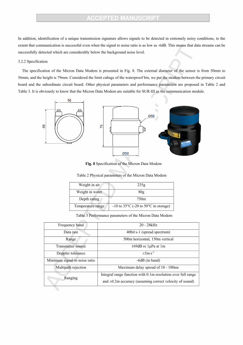
The specification of the Micron Data Modem is presented in Fig. 8. The external diameter of the sensor is from 50mm to
56mm, and the height is 79mm. Considered the limit cubage of the waterproof bin, we put the modem between the primary circuit
board and the subordinate circuit board. Other physical parameters and performance parameters are proposed in Table 2 and
Table 3. It is obviously to know that the Micron Data Modem are suitable for SUR-III as the communication module.
Fig. 8 Specification of the Micron Data Modem
Table 2 Physical parameters of the Micron Data Modem
Weight in air 235g
Weight in water 80g
Depth rating 750m
Temperature range -10 to 35°C (-20 to 50°C in storage)
Table 3 Performance parameters of the Micron Data Modem
Frequency band 20 - 28kHz
Data rate 40bit·s-1 (spread spectrum)
Range 500m horizontal, 150m vertical
Transmitter source 169dB re 1μPa at 1m
Doppler tolerance ±5m·s-1
Minimum signal to noise ratio -6dB (in band)
Multipath rejection Maximum delay spread of 10 - 100ms
Ranging Integral range function with 0.1m resolution over full range
and ±0.2m accuracy (assuming correct velocity of sound)

3.3 Control Circuit Design
A bilayer structure was employed for the control system to obtain data from various sensors, meanwhile control the outputs of
ports after calculation processing. The chip used on primary cuicuit board is TMS320f28335, it was adopted for the data collection
and disposing calculation. The Atmega2560 processor is taken as the main chip of the subordinate side to control the propulsion
system. So, the hardware of the control system is designed to be a two-level architecture, which are the primary circuit board and
the subordinate circuit board. Fig.9 shows the configuration of the whole hardware circuit. Fig.10 presents the prototype of the
control circuitry.
The primary side includes TMS320f28335 processor, MEMS IMU, depth sensor, communication sensor, and data-storage
equipment. The subordinate side is compose of Atmega2560 processor, 4 DC motor thrusters and 8 steering motors. The DSP
processor will receive the datas from sensor subsystems, then the datas will be disposed with preinstall algorithm. The correct
corresponding commond will be sent from DSP processor to AVR processor. The Atmega2560 will give the directive to actuator
for finishing the motions needed. The Groups of lithium battery provided the power to the propulsion, control, and sensor
subsystems. Especially, the power unit for the control subsystem is separated to avoid the interference between the primary circuit
board and the subordinate circuit board. As is shown in Fig.10.
Fig. 9 The hardware architecture of the SUR-III
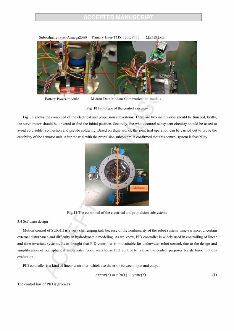
Fig. 10 Prototype of the control circuitry
Fig. 11 shows the combined of the electrical and propulsion subsystems. There are two main works should be finished, firstly,
the servo motor should be tinkered to find the initial position. Secondly, the whole control subsystem circuitry should be tested to
avoid cold solder connection and pseudo soldering. Based on these works, the joint trial operation can be carried out to prove the
capability of the actuator unit. After the trial with the propulsion subsystem, it confirmed that this control system is feasibility.
Fig.11 The combined of the electrical and propulsion subsystems
3.4 Software design
Motion control of SUR-III is a very challenging task because of the nonlinearity of the robot system, time-variance, uncertain
external disturbance and difficulty in hydrodynamic modeling. As we know, PID controller is widely used in controlling of linear
and time invariant systems. Even thought that PID controller is not suitable for underwater robot control, due to the design and
simplification of our spherical underwater robot, we choose PID control to realize the control purposes for its basic motions
evaluation.
PID controller is a kind of linear controller, which use the error between input and output:
(1)
The control law of PID is given as
380mm

1
0 (2)
where kp is the proportional gain, TI is time of integral, TD is the time of derivation. For our robot, we proposed another controller
to achieve high control precision accuracy to resist the large turbulence in the ocean. The controller we adopted is called the
FSMC (Fuzzy Sliding Mode Controller). The FSMC method has become one of the most popular MPC (Model Predictive
Control) methods both in industry and academia. It has been successfully implemented in many industrial applications, showing
good performance and a certain degree of robustness. Sliding mode control has the robustness, which can arouse the high
frequency dynamic performance. And the key point for using the sliding mode control is to decrease the buffeting [30][31]. The
combine of self-adaptation control and the sliding mode control are studied in [32]-[35]. The purpose is to overcome the
shortcomings of the sliding mode control. [36] proposed the nolinear output feedback control technology based on the sliding
mode method, and this method can realize the quick and accurate response in many circumstances. [37] also used the sliding
mode control method, which can make accurate control the angular position of underwater robots.
The dynamical equation of state in nonlinear system is:
1, 1 1
( , ) ( ) ( , ) ( )i i
n
x x i n
x f x t d t g x t u t
(3)
where T1 2( ) ( ), ( ), , ( ) nnx t x t x t x t is the state vector, ( , )f x t and ( , )g x t are unknown function in n . ( )d t is the
external disturbance, ( )u t is the control input. xn (t) is the component of the state vector, the physical meaning of the xn (t) is the
position of the robot in the state space. It can be the x,y,z, position of the robot in the surge, sway and heave motions. n is the
least number of the components which are enough to describe the state vector of the robot.
( 1) Tnd e e e e x x = (4)
the switch function is:
( 2) ( 1)1 2 1
n nns ,t c e c e c e e x ce = (5)
Where 1 2 1 1nc c c c = .
If the 0s = , then:
( 1) ( ) ( 1) ( ) ( )1 2 1 1 2 1
1( ) ( )
1
, , 0
n n n n nn n d
ni n
i di
s ,t c e c e c e e c e c e c e x x
c e x f t g t u t
x =
x x (6)
Thus, the equivalent controller of the FSMC is:
1
( ) ( )
1
1,
,
ni n
eq i di
u c e x f tg t
x
x (7)
The switch control is adopted to satisfy the reaching condition of sliding mode , ,s t s t s x x , so the switching
controller is:

1sgn
,su sg t
x
(8)
Then, we can get:
eq su u u (9)
And based on these, we can finally get:
sgn
0
ss s s s d t
s sd t
(10)
From it we can know that the control system is steady. When =0s t , the fuzzy controller chooses the equivalent control,
if 0s t , the switching control is adopted.
Then, the fuzzy controller could be designed as:
1
Z eq NZ eq s
eq NZ sZ NZ
NZ eq s
s u s u uu u s u
s s
s u u
(11)
The frame of fuzzy sliding mode controller is shown as follow:
Fig.12 Frame of Fuzzy Sliding Mode Controller
The FSMC controller is employed to control the orientation of the thrusters nozzle and enhance their flexibility. Fig.13 shows
a simplified flow chart of the control strategy.
For a given mission, the control unit will finish the initialization firstly, to initialize and calibrate the sensors. After
initialization, the initial attitude angle, depth, and position will be gained by control board. After comparing the current
parameters with the desired parameters, if we do not reach the target, the robot will realize it by calculating a suitable trajectory.
yx Objects
Fuzzy
Controller
Sliding mode
Controller

Fig.13 Flow chart of the software structure for SUR-III
4. Underwater Experiments
Underwater experiments were carried out to verify the performance of the SUR-III. The experimental environment is a 0.8m-
deep pool. Before the underwater experiments, times of joint trial operation with whole system were in progress. With all the
sensors added in control subsystem, we put the SUR-III into the underwater environment in the pool. Since it was a verification
experiment, we just tested the basic motions which could be fulfilled by SUR-III. Three direction motions had been checked,
which are Surge and Sway motions, closed-loop Yaw motion and the Heave motion.
It is important to evaluate the basic motions of our newly developed spherical underwater robot. Because of the symmetrical
shape of the shell, it is obvious that the motion characteristics of surge, sway, and heave may be similar. However, from another
point of view, surge and sway are motions in the XY-plane, they have similar hydrodynamic characteristics, while the motion
surface of heave is perpendicular to the XY-plane. Accordingly, we carried out separate experiments for horizontal and vertical
motion surfaces. For the horizontal plane, we carry out forward-and-turning experiments. For the vertical plane, the submerging-
and-floating-up experiments are carried out. Moreover, for the experimental prototype, we considered only a single rotational
DOF about the Z-axis, and hence the experiment on yaw motion was conducted. Fig. 14 illustrates the basic motions.
(a) Surge Motion (Moving Forward)
IMU Data collection
System Initialization
Alignment
Depth data collection
Attitude, velocity, position calculation
Depth calculation
Start
Achieve Target?
Kalman filter
Shut down thethrusters
Adjust the angle of thruster, turn on the DC motors
Compare the different between goal position and current position
FSMC controller
Motion planing
NY

(b) Heave Motions (Submergence and Floating)
(c) Yaw Motions (Spinning and Reversed-spin)
Fig.14 Basic Motions of the SUR-III
4.1 Surge-Sway Motion
The horizontal motion experiments combined surge and sway to verify the motion characteristics of the robot in the horizontal
plane. We carried out one group of experiment.
Forward-turning-right:
Step 1: surge (move forward along the X-axis);
Step 2: right steering (execute a 90◦ right turn);
Step 3: sway (move forward along the Y-axis).
Considered the spherical configuration of SUR-III, the hydraulic form will reduce the drag force from water, but the water
resistance is still a main influential factor in the surge and sway axial. The thrusters geometry layout made the robot easy to be
controlled, and realize the surge and sway motion breezily with pairs of thrusters. Fig.15 presents the velocity-displacement
relation chart in surge direction. It is clear that the relation between the velocity and displacement is approximate direct ratio.
The propulsive force of the DC motor thruster is set to be constant, so the average velocity of SUR-III in surge motion is
about 150 mm/s, which is labelld in red line in Fig.15. We have a 5 seconds reaction time. The test was lasted about 30s, and the
SUR-III advanced about 3800mm, which is displayed in black line in Fig.15. Increased speed was viable and deserving some
attention. Since the max velocity of the SUR-II is up to 100mm/s. The merit of the new structure of propulsion system is
impressive. The surge-sway motion trajectory is illustrated in Fig.16, and the trajectory of the SUR-II in same condition is also
showed for comparison.

Fig.15 Velocity-Displacement relation chart in surge direction
Fig.16 Trajectory of surge-sway motion
As is shown in Fig.16, there are two groups of curves describe the surge and sway motions finished by the SUR-II and SUR-
III respectively. There are theoretic results and experimental results in every group of curves. The green curve and blue curve
stand for the theoretic motion trajectories finished by SUR-II and SUR-III respectively. The purple and red curve express the
actual moving trajectories of SUR-II and SUR-III in surge-sway motion tests. This experimentation lasted 140s.
At the beginning of this test, two kinds of the SURs all kept the course in straight of surge direction for about 1000mm. Then
the DSP gave a comnond to turn right with the help of IMU. Since the influence of drag force, two robots all finished the sway

motion earlier than theoretical value. It should be noted at that the SUR-III had a less turning radius benefited from the
remarkable thrusters distribution. The profit of the improved propulsion system structure reflected again.
4.2 Yaw Motion
This experiment is to proof the flexibility and stability of the controller and closed loop control algorithm. To verify the
performance of control subsystem and sensor subsystem, we gave a external disturbance by hands to check the recovery
capability in yaw direction. The IMU sensor was responsible for measuring the rotational angle. Fig.17 shows the process of the
yaw motion test. Fig.18 proposes the results of this test.
Fig.17 Yaw motion test
At the initialization phase of this test, the SUR-III keep steady in the pool, however, it gyrated about 20 degree from original
location aroud Z-axis along clockwise sense. The reason is that the instantaneous inequality force provided by thrusters and the
influence of water flow in pool. Then we gave a cornering force in counter-clockwise direction after 1.6 seconds, The robot had a
rotational motion about 90 degree. The IMU sensed the angle changed, sent the drift angle to control unit. The DSP will drive the
propulsion system to reduce the drift angle and turn the robot back to original location. This stage lasted 5 seconds. At the end of
this process, FSMC controller need a fluctuation to adjust the attitude of the robot. The performance of the FSMC controller is
acceptable and efficient.
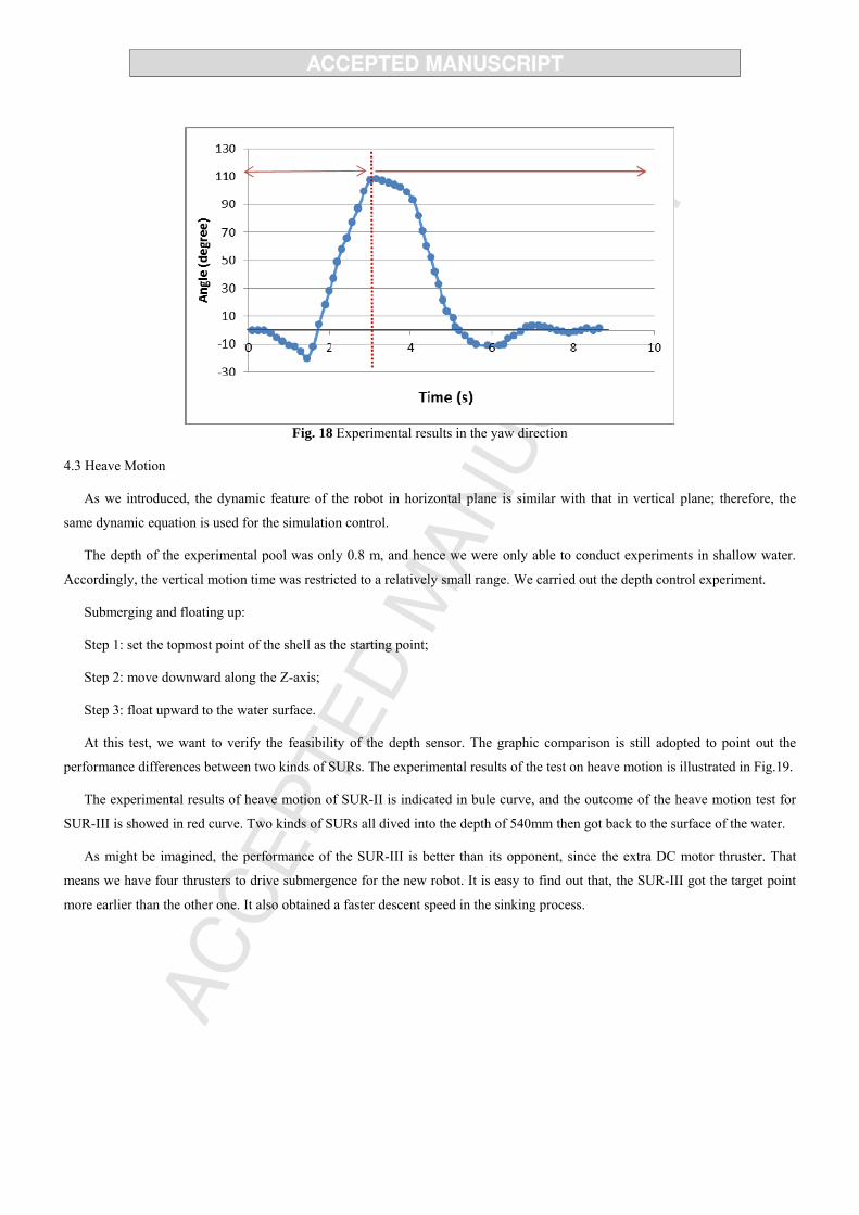
Fig. 18 Experimental results in the yaw direction
4.3 Heave Motion
As we introduced, the dynamic feature of the robot in horizontal plane is similar with that in vertical plane; therefore, the
same dynamic equation is used for the simulation control.
The depth of the experimental pool was only 0.8 m, and hence we were only able to conduct experiments in shallow water.
Accordingly, the vertical motion time was restricted to a relatively small range. We carried out the depth control experiment.
Submerging and floating up:
Step 1: set the topmost point of the shell as the starting point;
Step 2: move downward along the Z-axis;
Step 3: float upward to the water surface.
At this test, we want to verify the feasibility of the depth sensor. The graphic comparison is still adopted to point out the
performance differences between two kinds of SURs. The experimental results of the test on heave motion is illustrated in Fig.19.
The experimental results of heave motion of SUR-II is indicated in bule curve, and the outcome of the heave motion test for
SUR-III is showed in red curve. Two kinds of SURs all dived into the depth of 540mm then got back to the surface of the water.
As might be imagined, the performance of the SUR-III is better than its opponent, since the extra DC motor thruster. That
means we have four thrusters to drive submergence for the new robot. It is easy to find out that, the SUR-III got the target point
more earlier than the other one. It also obtained a faster descent speed in the sinking process.

Fig. 19 Experimental results of the heave motion test
4.4 Multi Depth
Since the robot may be required to work at different depths to perform one task, we conducted a test using multiple depths.
In this test, we assumed that the robot had three target positions at different depths. The robot started by floating on the surface.
Then, the robot was to descend to depths of 600, 700, and 800 mm, stopping at each depth for a few seconds, and then return to
depths of 700 and 600 mm. This pattern was then repeated. We corrected for the difference between the location of the depth
sensor and the geometric center of the robot. Fig. 20 shows the process of the multi depth control.
The results are shown in Fig. 21. The red line gives the set point for the motion control, and the black line gives the actual
depth of the robot. The system initialization and sensor calibration were completed at the start of the test. About 10s later, the
robot was driven to its first depth. Because the robot had a large amount of inertia in the water, the maximum overshoot of the
experiment was about 50 mm. The change in the direction of the propulsive force was nonlinear due to the control variables,
resulting in a robot trajectory that corresponded to simple harmonic motion. At least 10s were required to reach an acceptable
stable state at each depth.

Fig. 20 Multi-depth control experiment
0 20 40 60 80 100 120120
100
80
60
40
20
0
Depth Set point
Dep
th (
cm)
Time (s)
Fig. 21 Experimental results of multiple-depth control
5. Conclusion
We improved our previous generation spherical underwater robot, the SUR-II, and developed a novel spherical underwater
robot named SUR-III. To realize more creationary motions, we redesigned the propulsion system. The propulsion system is made
up 4 DC motor thrusters and 8 steering motors. Every two thrusters form an angle of 90 degree in the equatorial plane of the robot,

and the orientation of the nozzles are adjusted by pairs of the servo motors. The innovativeness structure will help our SUR-III to
finish some “acrobatic manoeuvres” which almost impossible for the previous SURs. Meanwhile, the SUR-III will be benefit to
the energy conservation, the reason has been explained in the published papers. We also developed the new control system for
the new structure. Particularly, we integrate the communication module-Micron Data Modem into the control subsystem. It will
be possible to send commond to SUR-III off shore. Based on the manufactured prototype, series of underwater experiments was
carried out to test and verify the performance of the SUR-III. We held the experiments on tesing the surge, yaw, and heave
motions. The results shows that the SUR-III can finish all the basic motions within a tolerable error. Furthermore, the
performance of SUR-III is more outstanding than the previous ones.
The purpose to develop the new structure of the propulsion system is to finish the more courageous motions. Such as, oblique
movement, omnidirectional rolling motion, even the high speed cruis with operationing of four thrusters. We will keep working
on the more appropriate control algorithm to inspire the potential and develop more capabilities of SUR-III. In addition, based on
the communication module, the multi-SUR robot system is not a dream. We have confidence to realize the communication
between two robots, and ask the multi-robot system to cooperate and work together to complete the mulriple missions.
ACKNOWLEDGMENT
This research is supported by Young scholars development fund of swpu (201699010118).

REFSERENCES
1. Giacomo Marani, Song K. Choi, Junku Yuh. Underwater autonomous manipulation for intervention missions AUVs.
Ocean Engineering, Vol. 36, No. 1, pp. 15-23, 2009
2. Mohan Santhakumar, Thondiyath Asokan. Investigations on the hybrid tracking control of an underactuated autonomous
underwater robot. Advanced Robotics, Vol. 24, No. 11, pp. 1529-1556, 2010
3. Q. Pan, S. Guo and T. Okada. A novel hybrid wireless microrobot. International Journal of Mechatronics and Automation,
Vol. 1, No. 1, pp. 60-69, 2011
4. B. Gao, S. Guo and X. Ye. Motion-control analysis of ICPF-actuated underwater biomimetic microrobots. International
Journal of Mechatronics and Automation, Vol. 1, No. 2, pp.79-89, 2011
5. S. W. Kandebo, AW&ST and AUVSI International Guide to Unmanned Vehicles. New York: McGraw-Hill, Inc., 1997
6. S. X. Wang, X. J. Sun, Y. H. Wang. Dynamic Modeling and Motion Simulation for A Winged Hybrid-Driven Underwater
Glider. China Ocean Eng, Vol. 25, No. 1, pp. 97-112, 2011
7. K. P. Valavanis, D. Gracanin, M. Matijasevic, R. Kolluru and G. A. Demetriou. Control architectures for autonomous
underwater vehicle. Control Systems, Vol. 17, No. 6, pp.48-64, 1997
8. Li Y, Guo S, Yue C. Preliminary concept of a novel spherical underwater robot. International Journal of Mechatronics and
Automation, Vol. 5, No. 1, pp. 11-21, 2015
9. H.T. Choi, A.Hanai, S.K. Choi and J.Yuh. Development of an underwater robot, ODIN-III. Proceedings of the 2003 IEEE
International Conference on Intelligent Robots and Systems, Vol. 5, No. 1, pp. 836-841, 2003
10. S.K. Choi, J. Yuh. Application of non-regressor-based adaptive control to underwater robots: experiment. Computers and
Electrical Engineering, Vol. 26,No. 2, pp.187-194, 2000
11. S.A. Watson, D. Crutchley and P. N. Green. The mechatronic design of a micro-autonomous underwater vehicle (µAUV).
International Journal of Mechatronics and Automation, Vol. 2, No. 3, pp. 157-168, 2012
12. S.A. Watson, D. Crutchley and P. N. Green. The Design and Technical Challenges of a Micro-Autonomous Underwater
Vehicle (μAUV). Proceedings of the 2011 IEEE International Conference on Mechatronics and Automation, Vol. 26,No. 2,
pp.567-572, 2011
13. S.A. Watson, P. N. Green. Propulsion systems for micro-Autonomous Underwater Vehicles (μAUVs). In: Proceedings of
the 2010 IEEE International Conference on Robotics Automation and Mechatronics, Vol. 5,No. 3,pp.435-440, 2010
14. S.A. Watson, D. Crutchley and P. N. Green. A De-Coupled Vertical Controller for Micro-Autonomous Underwater
Vehicles (μAUVs). Proceedings of the 2011 IEEE International Conference on Mechatronics and Automation. Vol. 1,No.
1,pp.561-566, 2011
15. S. Guo, J. Du, X. Ye, R. Yan and H. Gao. The computational design of a water jet propulsion spherical underwater vehicle.
Proceedings of the 2011 IEEE International Conference on Mechatronics and Automation, Vol. 2,No. 3, pp. 2375-2379,
2011
16. S. Guo, J. Du, X. Ye, H. Gao, Y. Gu. Realtime adjusting control algorithm for the spherical underwater robot.
INFORMATION-An International Interdisciplinary Journal, Vol. 13, No. 6, pp. 2021-2029, 2010

17. X. Lan, H. Sun, Q. Jia. Principle and dynamic analysis of a new-type spherical underwater vehicle. Journal of Beijing
University of Posts and Telecommunications, Vol. 33, No. 3, pp.20-23, 2010
18. S. X. Wang, X. J. Sun, Y. H. Wang. Dynamic Modeling and Motion Simulation for a Winged Hybrid-Driven Underwater
Glider,” China Ocean Eng, Vol. 25, No.1, pp.97-112, 2011
19. Khalid Isa and M. R. Arshad. Dynamic Modeling and Motion Simulation for a Winged Hybrid-Driven Underwater Glider,
Indian Journal of Geo-Marine Science, Vol. 42 No.8, pp.971-979, 2013
20. X. Lin and S. Guo: Development of a spherical underwater robot equipped with multiple vectored water-jet-based
thrusters. Journal of Intelligent and Robotic Systems, Vol. 67, No.23, pp. 307-321, 2012
21. S. Guo, X. Lin, K. Tanaka and S. Hata: Development and control of a vectored water-jet-based spherical underwater
vehicle. Proceedings of the 2010 IEEE International Conference on Information and Automation, Vol. 11,No. 4, pp. 1341-
1346, 2010
22. X. Lin, S. Guo, K. Tanaka and S. Hata: Underwater experiments of a water-jet-based spherical underwater robot.
Proceedings of the 2011 IEEE International Conference on Mechatronics and Automation, Vol. 5,No. 3, pp. 738-742, 2011
23. X. Lin, S. Guo, C. Yue and J. Du: 3D modelling of a vectored water jet-based multi-propeller propulsion system for a
spherical underwater robot. International Journal of Advanced Robotic Systems, Vol.10, No.9, pp. 209-215, 2013
24. C. Yue, S. Guo, X. Lin, J. Du: Analysis and Improvement of the Water-jet Propulsion System of a Spherical Underwater
Robot. Proceedings of 2012 IEEE International Conference on Mechatronics and Automation, pp.2208-2213, 2012
25. C. Yue, S. Guo, M. Li: Electrical System Design of a Spherical Underwater Robot (SUR-II). Proceeding of 2013 IEEE
International Conference on Information and Automation. Vol. 2,No. 3, pp.1212-1217, 2013
26. C. Yue, S. Guo, M. Li: ANSYS FLUENT-based Modeling and Hydrodynamic Analysis for a Spherical Underwater Robot.
Proceedings of 2013 IEEE International Conference on Mechatronics and Automation. Vol. 1,No. 2,pp. 1577-1581, 2013
27. C. Yue, S. Guo, M. Li, Yaxin Li: Passive and Active Attitude Stabilization Method for the Spherical Underwater Robot
(SUR-II). Proceedings of 2013 IEEE International Conference on Robotics and Biomimetics. Vol. 7,No. 8, pp. 1019-1023,
2013
28. C.Yue, S. Guo, L.Shi: Hydrodynamic Analysis of a Spherical Underwater Robot: SUR-II. International Journal of
Advanced Robotic Systems. Vol. 10, No.4, 2013
29. C.Yue, S.Guo, L.Shi, J. Du: Characteristics evaluation of the vertical motion of a spherical underwater robot. Proceedings
of 2012 IEEE International Conference on Robotics and Biomimetics, Vol. 1,No. 13, pp.759-764, 2012
30. Jinkun Liu. The sliding mode control for the simulation [M]. Tsing Tsinghua University Press, 2005: 1-15, pp,109-187.
31. J. Guo, F.-C.Chiu, C.-C. Huang. Design of a sliding mode fuzzy controller for the guidance and control of an autonomous
underwater vehicle[J]. Ocean Engineering. 2003, 30(16): 2137-2155P
32. Shiuh-Jer Huang, Hung-Yi Chen. Adaptive sliding controller with self-tuning fuzzy compensation for vehicle suspension
control[J]. Mechatronics. 2006, 16(10): 607-622P
33. Mehdi Roopaei, Bijan Ranjbar Sahraei, Tsung-Chih Lin. Adaptive sliding mode control in a novel class of chaotic
systems[J]. Communications in Nonlinear Science and Numerical Simulation. 2010, 15(12): 4158-4170P

34. Meysar Zeinali, Leila Notash. Adaptive sliding mode control with uncertainty estimator for robot manipulators[J].
Mechanism and Machine Theory. 2010, 45(1): 80-90P
35. Mohammad Motamedi, Mohammad Taghi Ahmadian, Gholamreza Vossoughi, Seyed Mehdi Rezaei, Mohammad
Zareinejad. Adaptive sliding mode control of a piezo-actuated bilateral teleoperated micromanipulation system[J].
Precision Engineering. 2011, 5(2): 309-317P
36. Alessandro Pisano, Elio Usai. Output-feedback control of an underwater vehicle prototype by higher-order sliding
modes[J]. Automatica. 2004, 40(9): 1525-1531P
37. Huanyin Zhou, Kaizhou Liu, Xisheng Feng. State feedback sliding mode control without chattering by constructing
Hurwitz matrix for AUV movement[J]. International Journal of Automation and Computing. 2011, 8(2): 262-268P
Biography notes:
Yaxin Li received the B.S. degree in college of automation from Chongqing University (CQU), China, in 2010 and
received the M.S. degree in Electronics and Communication Engineering at University of Electronic Science and
Technology of China, in 2013. Mr. Li received his Ph.D. degree in intelligent machine system, Kagawa University,
Japan in 2016. He has published about 5 conference papers and 2 journal paper in recent years. His current research
interests are spherical underwater robotics; biomedical-related robotics.
Shuxiang Guo received his Ph.D. degree mechanoinformatics and systems from Nagoya University, Nagoya, Japan,
in 1995. He had been a Full Professor at the Department of Intelligent Mechanical System Engineering, Kagawa
University, Takamatsu, Japan, since 2005. He is also the Chair Professor in Key Laboratory of Convergence Medical
Engineering System and Healthcare Technology, Ministry of Industry and Information Technology, Beijing Institute
of Technology, China. He has published about 470 refereed journal and conference papers. His current research
interests include biomimetic underwater robots and medical robot systems for minimal invasive surgery, micro
catheter system, micropump, and smart material (SMA, IPMC) based on actuators.
Yu Wang received her B.S. and M.S. degrees from Chongqing University, China in 2010 and Xi’an Jiaotong
University, China in 2013 respectively. Her received Ph.D. in Intelligent Mechanical Systems from Kagawa
University, Japan in 2016. Currently, she is working at School of Electronics and Information Engineering in
Southwest Petroleum University, Chengdu, China. Her research interests include robotic endovascular surgery;
virtual-reality simulator and smart material based actuators. She has already published about 10 refereed journal and
conference papers.

The novel spherical underwater robot (SUR) with thrust vector has been developed to improve the mobility of the environment observing underwater vehicle.
The propulsion system of the robot is composed of 4 water-jet thrusters and 8 steering motors.
A bilayer structure is employed for the control system to obtain data from various sensors, meanwhile drive the actuators after calculation processing.
The Micron Data Modem is integrated into the electrical system, which can realize the data transmission and communication between multi-SURs in future.