Embed Size (px)
Citation preview

SMARTLINK™ Intelligent Valve Actuator Page 7303
11/04
Design and Application Details
Principle of Operation
As shown in the block diagram below, theSMARTLINK™ Intelligent Valve Actuator is driven by aposition command signal via a 4-20mA signal from theuser’s process controller. (A 4mA signal will drive thevalve to its minimum position and a 20mA signal willdrive the valve to its maximum position.) The positioncommand signal is translated by the Control Interfaceinto a digital command that is sent to the valve over adedicated communications network. The Valve Actua-tor performs a high-speed position control loop toachieve the position setpoint received from the ControlInterface. The valve position is continuously transmit-ted digitally by the Valve Actuator back over thecommunications network to the Control Interface. Thedigitally received valve position feedback is thentranslated by the Control Interface into a 4-20mAoutput signal for PLC monitoring if required.
The SMARTLINK™ Control Interface includes a set
of switches and lights to allow the user to perform thefollowing functions:
1) Configure operating parameters, such as loss ofsignal operation and high/low position limits,
2) Display alarm codes,3) “Lock” the device electronically to prevent
tampering,4) Customize the installed valve characteristic, and,5) Locally control valve movement.The communications network between the Valve
Actuator and the Control interface is composed of 4wires: 24VDC, Common, Data-A, and Data-B. TheControl Interface continuously monitors Valve Actuatorstatus over the digital network, and updates severalrelay driver outputs. These outputs are used to driveoptional (Maxon or user-supplied) interface relays forcontrol enable, alarm, manual control, and high/lowposition limit indication.
SMARTLINK™ Valve Actuator AssemblyBlock Diagram
4-20mATerminal
Block
RelayTerminal
Block
ControlNetworkTerminal
Block
Position Command
Position Feedback
(2) InputInterface
Relays
(5) OutputInterface
Relays
24 VDCPowerSupply
SMARTLINKControl
Interface
SMARTLINKValve
Actuator
Fro
m /
To U
ser'
s P
rocess
Contr
oll
er
Maxon or User-Supplied DIN Rail Assembly
VACTerminal
Block
AC
Pow
er
NOTES:1. Non-shaded blocks indicate optional Maxon-supplied equipment2. Shaded blocks indicate SMARTLINK required components

SMARTLINK™ Intelligent Valve ActuatorPage 7304
Table of Contents
Butterfly Valves:Model Number Description ...................................................................................................................7307Capacities and Specifications ..............................................................................................................7308Dimensions ..........................................................................................................................................7312
Ball Valves:Model Number Description ...................................................................................................................7319Capacities and Specifications ..............................................................................................................7321Dimensions ..........................................................................................................................................7323
Control Actuator:Model Number Description ...................................................................................................................7326Dimensions ..........................................................................................................................................7327
Spare Actuator:Model Number Description ...................................................................................................................7328
Control Interface:Model Number Description ...................................................................................................................7329Dimensions ..........................................................................................................................................7330

SMARTLINK™ Intelligent Valve Actuator Page 7305
Model Number DescriptionButterfly Valves
Configured Item Number Valve Body Actuator
Bod
yC
onne
ctio
n
Val
veS
ize
Flo
wC
apac
ity
Ser
ies
Bod
yS
eals
Bod
yM
ater
ial
Bod
yIn
tern
als
Torq
ueR
atin
g
Sof
twar
eV
ersi
on
Lang
uage
0100 S SLCV - A A 1 1 - 1 1B A
Size0000 - Actuator Only0100 - 1"0125 - 1.25"0150 - 1.5"0200 - 2"0250 - 2.5"0300 - 3"0400 - 4"0600 - 6"0800 - 8"1000 - 10"1200 - 12"1400 - 14"1600 - 16"
Flow Capacity0 - Actuator OnlyS - Standard
SeriesSLCV - SMARTLINK ButterflyValve
Body ConnectionA - ANSI FlangeM - "M" Style FlangeX - Special* - Actuator Only
Body SealsA - Buna-NB - VitonX - Special* - Actuator Only
Body Material1 - Cast Iron2 - Carbon Steel3 - Brass5 - Stainless SteelX - Special* - Actuator Only
Body Internals1 - Trim Package 12 - Trim Package 1, Oxy Clean5 - Trim Package 26 - Trim Package 2, Oxy CleanX - Special* - Actuator Only
Torque Rating1 - 300 in-lbsX - Special* - Valve Body Only
Software Version [1]V1 - Version 11A - Version 1A1B - Version 1BXX - Special** - Valve Body Only
LanguageA - EnglishX - Special* - Valve Body Only
The model number shown on the valve nameplate canaccurately identify every Maxon SMARTLINK™Butterfly Valve. The example below shows a typicalSMARTLINK™ Butterfly Valve model number, alongwith the available choices for each item represented in
the model number. The first three choices determinethe valve's configured item number. The next eightcharacters in the model number identify valve bodyand actuator options.
[1] The latest version is the default; proper version must be specified for replacement items
Trim Package Options and Typical Materials:1 - 300 Series Stainless Steel stem, 300 Series Stainless Steel disc and Bronze bushings2 - 300 Series Stainless Steel stem, 300 Series Stainless Steel disc and PEEK bushings
11/04

SMARTLINK™ Intelligent Valve ActuatorPage 7306
Valve Body CapacitiesButterfly Valves
"4urht"1-elbaTecnamrofrePydoBevlaVylfrettuB
eziSmuminiM
elballortnoCgnitaRvC
mumixaMgnitaRvC
telnImumixaMerusserP
)gisp(
ydoBmumixaMerusserP
)gisp(
)1etonees(erutarepmeTdiulFmumixaM
)F°(leetS&norI )F°(ssarB
"1 05. 72 001 001 052 004
"52.1 06. 07 001 001 052 004
"5.1 07. 501 001 001 052 004
"2 03.1 091 001 001 052 004
"5.2 04.2 062 09 001 052 004
"3 00.3 063 06 001 052 004
"4 00.5 057 03 001 052 ---
noxaMtcatnoc,F°851nahtretaergsierutarepmetdiulffI.ylnostnenopmocydobevlavfosnoitatimiltcipeddetsilserutarepmeT:1etoN.ylbmessaydobevlavotrotautcA™KNILTRAMSgniylppanehw
"61urht"6-elbaTecnamrofrePydoBevlaVylfrettuB
eziSmuminiM
elballortnoCgnitaRvC
mumixaMgnitaRvC
telnImumixaMerusserP
)gisp(
ydoBmumixaMerusserP
)gisp(
diulFmumixaM)F°(erutarepmeT
)1etonees(
"6 5.21 5241 5 001 052
"8 22 0052 5 001 052
"01 53 0054 5 001 052
"21 05 0046 5 001 052
"41 76 0088 5 001 052
"61 88 00711 5 001 052
nahtretaergsierutarepmetdiulffI.ylnostnenopmocydobevlavfosnoitatimiltcipeddetsilserutarepmeT:1etoN.ylbmessaydobevlavotrotautcA™KNILTRAMSgniylppanehwnoxaMtcatnoc,F°851
1/04

Valve Body Assembly SpecificationsButterfly Valves
4 89
2
6
1
12
10
11
3
5
7
87
8
slairetaMydoB
.oNmetI noitpircseDedoClairetaM
1 2 3 5
1 ydoBevlaVnorItsaC
0003.rG951AMTSAleetSnobraC
BCW.rG612AMTSA
ssarB26BMTSA
00638C.oNSNU
leetSsselniatSM8FC.rG153AMTSA
slaeSydoB.oNmetI noitpircseD lairetaM
7 gniR-OerasnoitpolairetamdradnatS
notiVdnaN-anuB8 gniR-O
9 gniR-O
slairetaMegakcaPmirT
.oNmetI noitpircseDegakcaPmirTlanretnI
1 2
2 metSevlaV 0003G.rG751AMTSA,leetSsselniatS303
3 csiDylfrettuB 00403S.oNSNU403epyT042AMTSA,leetSsselniatS403
4 gnihsuBpoTeznorB
485Bdna505B,172BMTSA00239C.oNSNU
KEEP5 gnihsuBmottoB
6 gnihsuBmihSpoT
01 wercS leetSsselniatS8-81
11 rehsaW leetSsselniatS403
21 gniRgniniateR leetSsselniatS613
SMARTLINK™ Intelligent Valve Actuator Page 7307
11/04

2
657
1
4
8
9
11
10
3
4
12
Valve Body Assembly SpecificationsButterfly Valves
slairetaMydoB
.oNmetI noitpircseDedoClairetaM
1
1 ydoBevlaVnorItsaC
0003.rG951AMTSA
slaeSydoB.oNmetI noitpircseD lairetaM
6 gniR-ON-anuBsinoitpolairetamdradnatS
7 gniR-O
slairetaMegakcaPmirT.oNmetI noitpircseD 1egakcaPmirTlanretnI
>eziSevlaV "8&"6 "61hguorht"01
2 metSevlaVleetSsselniatS613
672AMTSA
3 csiDylfrettuBleetSsselniatS403
000403S.oNSNU761AMTSAleetSnobraC
08101G.oNSNU801AMTSA
4 gnihsuBmottoB&poT eznorB00239C.oNSNU485Bdna505B,172BMTSA5 gnihsuBmihS
8 wercS leetSsselniatS403 leetSnobraCdetalPcniZ
9 rehsaW leetSsselniatS613 leetSnobraCdetalPcniZ
01 gniRgniniateR leetSnobraC00901G-00601G.oNSNU0901-0601EAS11 gniRgniniateR
21 gulPepiPleetSyollA
07304GSNU223AMTSA
SMARTLINK™ Intelligent Valve ActuatorPage 7308

Valve Body Assembly SpecificationsButterfly Valves
snoitacificepSlairetaMylbmessAydoBevlaVKNILTRAMS.oNmetI noitpircseD snoitacificepSlairetaMtnenopmoCKNILTRAMS
A1 ylbmessa-buSydoBevlaV 1137&0137segaprepylbmessA
A2 niPgnirpSgnitacoL leetSnobraCdetalPcniZ
A3 tekcarBretpadA munimulA6T971BMTSA
†A4 wercSpaCdaeHtekcoS leetSnobraCdetalPcniZ
A5 gnilpuoC leetSsselniatS303epyT285AMTSA
A6 ralloCgnikcoL leetSsselniatS303epyT8-81
A7 niPgnirpS leetSnobraCdetalPcniZ
A8 niPlewoD leetSsselniatS303
A9 wercSpotSdraH leetSsselniatS8-81
A01 tuNpotSdraH leetSsselniatS
†A11 etalPrevoC munimulA
"4urht"1sezisnoylnodesusmetiesehT-†
3A
8A
7A
4A
6A
10A
9A
5A
2A
11A
4A
1A
SMARTLINK™ Intelligent Valve Actuator Page 7309
11/04

Dimensions (in inches)
1" SMARTLINK™ Butterfly Valve 1.25" SMARTLINK™ Butterfly Valve
"A"noisnemiDegnalFnorI dedaerhT 78.2
leetSdedaerhT 51.3
dedleWtekcoS 48.2
ssarBdedaerhT 18.2
puCredloS 15.3
"A"noisnemiDegnalFnorI dedaerhT 50.3
leetSdedaerhT 21.3
dedleWtekcoS 50.3
ssarBdedaerhT 50.3
puCredloS 36.3
4.0
10.2
2.0
3.5
A
12.7
3.2
4.4
2.7
3.5 dia.bolt circle
.62 dia.4 holes
5.0 dia.1.4 dia.
M8 - 1.25 tap.62 deep2 holes
1 1
1.31
.5" NPT Threads
45˚
4.0
10.2
2.0
3.0
A
12.2
2.9
4.4
2.5
.62 dia. 4 holes
4.2 dia.
3.1 dia.bolt circle
1.1 dia.
M8 - 1.25 tap.62 deep2 holes
1.31
1" 1"
.5" NPT Threads
45˚
Approximate weight: 22 lbs, w/flanges 26 lbs Approximate weight: 25 lbs, w/flanges 29 lbs.
SMARTLINK™ Intelligent Valve ActuatorPage 7310

Dimensions (in inches)
1.5" SMARTLINK™ Butterfly Valve 2" SMARTLINK™ Butterfly Valve
"A"noisnemiDegnalFnorI dedaerhT 72.3
leetSdedaerhT 32.3
dedleWtekcoS 42.3
ssarBdedaerhT 51.3
puCredloS 88.3
"A"noisnemiDegnalFnorI dedaerhT 34.3
leetSdedaerhT 65.3
dedleWtekcoS 15.3
ssarBdedaerhT 27.3
puCredloS 26.4
4.0
10.2
2.0
3.5
A
12.7
3.2
4.4
2.8
3.9 dia.bolt circle
5.0 dia.
1.7 dia.
M8 - 1.25 tap.62 deep2 holes
1" 1"
.62 dia.4 holes
1.31
.5" NPT Threads
45˚
4.0
10.2
2.0
3.5
A
12.7
3.4
4.4
3.0
4.8 dia.bolt circle
.75 dia.4 holes
6.0 dia.
2.2 dia.
M8 - 1.25 tap.62 deep2 holes
1.69
1 1
1"
45˚
.5" NPT Threads
Approximate weight: 28 lbs, w/flanges 34 lbs Approximate weight: 31 lbs, w/flanges 39 lbs.
SMARTLINK™ Intelligent Valve Actuator Page 7311
11/04

Dimensions (in inches)
2.5" SMARTLINK™ Butterfly Valve 3" SMARTLINK™ Butterfly Valve
"A"noisnemiDegnalFnorI dedaerhT 27.3
leetSdedaerhT 76.3
dedleWtekcoS 97.3
ssarBdedaerhT 08.3
puCredloS 72.5
"A"noisnemiDegnalFnorI dedaerhT 38.3
leetSdedaerhT 31.4
dedleWtekcoS 30.4
ssarBdedaerhT 20.4
puCredloS 90.5
4.0
10.2
2.0
4.0
A
13.2
4.2
4.4
3.8 5.5 dia.bolt circle
.75 dia.4 holes
7.5 dia.
2.6 dia.
1.81
M8 - 1.25 tap.62 deep2 holes
1 1
45˚
.5" NPT Threads
4.0
10.2
2.0
4.0
A
13.2
4.2
4.4
6.0 dia. bolt circle
.75 dia.4 holes
7.5 dia.
3.3 dia.
1.81
M8 - 1.25 tap.62 deep2 holes
1 1
3.8
45˚
.5" NPT Threads
Approximate weight: 39 lbs., w/flanges 53 lbs. Approximate weight: 44 lbs., w/flanges 62 lbs.
SMARTLINK™ Intelligent Valve ActuatorPage 7312

Dimensions (in inches)
4" SMARTLINK™ Butterfly Valve
"A"noisnemiDegnalFnorI dedaerhT 31.4
leetSdedaerhT 60.4
dedleWtekcoS 60.4
10.2
2.0
4.6
A
13.8
5.3
4.4
7.5 dia.bolt circle
.75 dia.8 holes
4.3 dia.
2.06
M8 - 1.25 tap.62 deep2 holes
1 1
4.9
4.0
9.0 dia.
.5" NPT Threads
22.5˚
6" SMARTLINK™ Butterfly Valve
.5" NPTThreads
6.1 dia.
6.1
1/2-13 UNC6 holes
7.75" dia.bolt circle
60˚
4.4
1.01.0
1.0
1.0
.438 deep4 holes
3.0
3.0
5.9
5.9
10.2
15.1
2.0
4.0
1.5
4.3
8.9 dia.
Approximate weight: 49 lbs., w/flanges 71 lbs Approximate weight: 55 lbs., w/flanges 71 lbs.
SMARTLINK™ Intelligent Valve Actuator Page 7313
11/04

Dimensions (in inches)
8" SMARTLINK™ Butterfly Valve 10" SMARTLINK™ Butterfly Valve
.5" NPTThreads
60˚
10.25 dia.bolt circle1/2-13 UNC
6 holes
8.0 dia.
11.8dia.
7.6
1.1
3.0
3.01.0
1.0
1.01.0
2.0
4.0
7.4
7.0
10.2
16.2
4.4
1.5
4.4
.438 deep4 holes
.5" NPTThreads
3.0
3.0
1.0
1.0
1.01.0
.438 deep4 holes
18.4
10.2
9.2
7.6
2.56.5
4.4
8.4
3.6
10.0 dia.
13.0 dia.
16.0 dia.
14.2 dia.bolt circle
2.04.0
1.0 dia. 12 holes
Note: Flanges are shipped loose.
Approximate weight: 61 lbs., w/flanges 91 lbs. Approximate weight: 66 lbs., w/flanges 139 lbs.
SMARTLINK™ Intelligent Valve ActuatorPage 7314

.5" NPTThreads
8.7
10.2
10.2
3.07.6
2.04.0
19.4
4.6
9.5
12.0dia.
1.0 dia.12 holes
16.0 dia.
19.0 dia.
17.0 dia.bolt circle
4.4
1.01.0
1.0
1.0
3.0
3.0
.438 deep4 holes
2
Dimensions (in inches)
12" SMARTLINK™ Butterfly Valve
14" SMARTLINK™ Butterfly Valve
.5" NPTThreads
1.01.0
1.01.0
3.0
3.0
4.4
13.2dia.
17.4dia.
18.8 dia.bolt circle
1.1 dia.12 holes
21.0 dia.
5.8
10.5
9.6
11.4
10.2
20.6
2.04.0
3.07.6
.438 deep4 holes
Note: Flanges are shipped loose.
Note: Flanges are shipped loose.
Approximate weight: 77 lbs., w/flanges 197 lbs.
Approximate weight: 109 lbs., w/flanges 266 lbs.
SMARTLINK™ Intelligent Valve Actuator Page 7315
11/04

Dimensions (in inches)
16" SMARTLINK™ Butterfly Valve
.5" NPTThreaded
1.01.0
1.0
3.0
3.0
4.4
23.5 dia.
21.2 dia.bolt circle
19.4 dia.
15.0 dia.
1.12 dia.16 holes
11.4
6.6
10.5
12.2
10.2
2.04.0
21.4
3.08.1
.438 deep4 holes
1.0
Note: Flanges are shipped loose.
Approximate weight: 134 lbs., w/flanges 343 lbs
SMARTLINK™ Intelligent Valve ActuatorPage 7316

Model Number DescriptionBall Valves
Configured Item Number Valve Body Actuator
Bod
yC
onne
ctio
n
Val
veS
ize
Ser
ies
Bod
y S
eals
& P
acki
ng
Bod
yM
ater
ial
Bod
yIn
tern
als
Torq
ueR
atin
g
Sof
twar
eV
ersi
on
Lang
uage
0100 7 SLBV - B E 2 1 - 1 1B A
Size0000 - Actuator Only0050 - .5"0075 - .75"0100 - 1"0125 - 1.25"0150 - 1.5"0200 - 2"
Flow Capacity0 - Actuator Only1 - 1/32" Slot2 - 1/16" Slot3 - 1/8" Slot4 - 3/16" Slot5 - 1/4" Slot6 - 30° V7 - 60° V8 - 90° V9 - Round Port
SeriesSLBV - SMARTLINK Ball Valve
Body ConnectionA - ANSI Flanged 150#B - ANSI ThreadedX - Special (see note 1)* - Actuator Only
Body Seals & PackingE - TeflonX - Special (see note 1)* - Actuator Only
Body Material2 - Carbon Steel5 - Stainless SteelX - Special (see note 1)* - Actuator Only
Body Internals1 - Trim Package 1X - Special (see note 1)* - Actuator Only
Torque Rating1 - 300 in-lbsX - Special* - Valve Body Only
Software Version [1]V1 - Version 11A - Version 1A1B - Version 1BXX - Special** - Valve Body Only
LanguageA - EnglishX - Special* - Valve Body Only
[1] The latest version is the default; proper version must be specified for replacement items
Note: Please see page 7308for all available ball valve options. These will require a special configuration.
Trim Package Options and Typical Materials:1 - 300 Series Stainless Steel Ball, 300 Series Stainless Steel Stem and Teflon Seat Rings
The model number shown on the valve nameplate canaccurately indentify every Maxon SMARTLINK™ BallValve. The example below shows a typicalSMARTLINK™ Ball Valve model number, along withthe available choices for each item represented in the
model number. The first three choices determine thevalve's configured item number. The next eight charac-ters in the model number identify valve body andactuator options.
SMARTLINK™ Intelligent Valve Actuator Page 7317
Flo
wC
apac
ity
11/04

SMARTLINK™ Intelligent Valve ActuatorPage 7318
nepO%.svvC-tneiciffeoCwolFeziS tresnI %0.0 %1.11 %2.22 %3.33 %4.44 %5.55 %7.66 %8.77 %9.88 %0.001
"5.
tolS"23/1 00.0 00.0 30.0 70.0 21.0 61.0 02.0 42.0 82.0 23.0
tolS"61/1 00.0 10.0 70.0 02.0 33.0 64.0 06.0 37.0 68.0 00.1
tolS"8/1 00.0 10.0 01.0 63.0 16.0 68.0 01.1 04.1 06.1 08.1
V°03 00.0 10.0 11.0 42.0 63.0 65.0 48.0 01.1 06.1 01.2
V°06 00.0 10.0 21.0 33.0 06.0 48.0 04.1 00.2 01.3 04.4
troPdnuoR 00.0 51.0 92.0 64.0 07.0 01.1 08.1 06.2 03.4 04.6
"57.
tolS"61/1 00.0 10.0 60.0 42.0 04.0 65.0 37.0 09.0 00.1 02.1
tolS"8/1 00.0 10.0 41.0 93.0 56.0 09.0 02.1 04.1 07.1 09.1
V°03 00.0 10.0 11.0 42.0 14.0 76.0 00.1 04.1 09.1 06.2
V°06 00.0 10.0 31.0 63.0 55.0 00.1 05.1 03.2 06.3 00.5
troPdnuoR 00.0 12.0 34.0 07.0 01.1 06.1 06.2 00.4 04.6 06.9
"1
tolS"61/1 00.0 30.0 01.0 04.0 76.0 49.0 02.1 05.1 07.1 09.1
tolS"61/3 00.0 30.0 22.0 28.0 04.1 09.1 05.2 01.3 05.3 00.4
V°03 00.0 30.0 12.0 65.0 00.1 06.1 04.2 04.3 06.4 02.6
V°06 00.0 30.0 03.0 87.0 02.1 03.2 06.3 03.5 03.8 06.11
V°09 00.0 30.0 84.0 02.1 03.2 05.3 04.5 07.7 08.01 01.21
troPdnuoR 00.0 85.0 02.1 09.1 08.2 03.4 00.7 05.01 00.71 00.62
"52.1
tolS"61/3 00.0 50.0 83.0 04.1 04.2 04.3 04.4 04.5 02.6 09.6
V°03 00.0 50.0 93.0 00.1 08.1 09.2 04.4 04.6 06.8 04.11
V°06 00.0 60.0 84.0 03.1 00.2 07.3 08.5 05.8 04.31 07.81
V°09 00.0 60.0 87.0 00.2 07.3 07.5 08.8 05.21 05.71 07.91
troPdnuoR 00.0 19.0 08.1 00.3 04.4 07.6 09.01 04.61 06.62 06.04
"5.1
tolS"61/3 00.0 50.0 74.0 08.1 00.3 02.4 04.5 08.6 07.7 06.8
V°03 00.0 50.0 14.0 02.1 01.2 05.3 02.5 06.7 03.01 07.31
V°06 00.0 60.0 75.0 07.1 00.3 06.5 01.9 02.31 08.91 04.82
V°09 00.0 60.0 00.1 08.2 05.4 01.8 04.31 07.91 09.03 01.74
troPdnuoR 00.0 05.1 00.3 08.4 02.7 00.11 00.81 00.72 00.44 05.56
"2
tolS"4/1 00.0 50.0 57.0 09.2 08.4 08.6 07.8 08.01 03.21 08.31
V°03 00.0 50.0 55.0 07.1 04.3 07.5 03.8 01.21 06.61 02.22
V°06 00.0 60.0 07.0 06.2 09.4 03.9 05.51 02.22 01.23 02.74
V°09 00.0 60.0 88.0 03.3 01.6 07.11 04.91 05.72 01.04 00.95
troPdnuoR 00.0 02.2 03.4 00.7 05.01 02.61 04.62 06.93 00.46 00.69
Valve Body CapacitiesBall Valves
Maximum Pressure is 300 psigMaximum Fluid Temperature is 158°F
SMARTLINK™ Intelligent Valve Actuator Page 7319
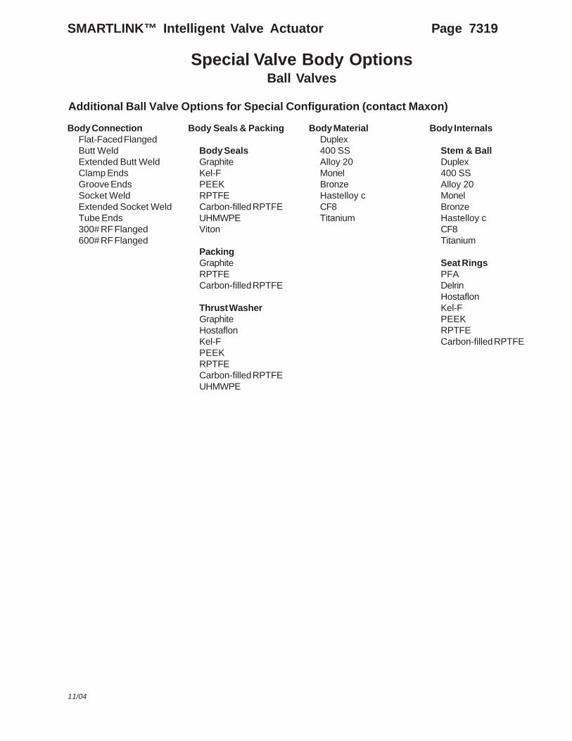
Special Valve Body OptionsBall Valves
Additional Ball Valve Options for Special Configuration (contact Maxon)
Body ConnectionFlat-Faced FlangedButt WeldExtended Butt WeldClamp EndsGroove EndsSocket WeldExtended Socket WeldTube Ends300# RF Flanged600# RF Flanged
Body Seals & Packing
Body SealsGraphiteKel-FPEEKRPTFECarbon-filled RPTFEUHMWPEViton
PackingGraphiteRPTFECarbon-filled RPTFE
Thrust WasherGraphiteHostaflonKel-FPEEKRPTFECarbon-filled RPTFEUHMWPE
Body MaterialDuplex400 SSAlloy 20MonelBronzeHastelloy cCF8Titanium
Body Internals
Stem & BallDuplex400 SSAlloy 20MonelBronzeHastelloy cCF8Titanium
Seat RingsPFADelrinHostaflonKel-FPEEKRPTFECarbon-filled RPTFE
11/04
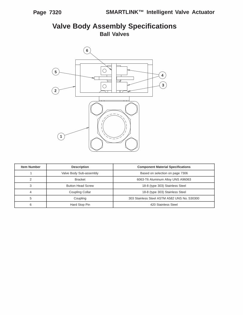
Valve Body Assembly SpecificationsBall Valves
rebmuNmetI noitpircseD snoitacificepSlairetaMtnenopmoC
1 ylbmessa-buSydoBevlaV 6037egapnonoitcelesnodesaB
2 tekcarB 36069ASNUyollAmunimulA6T-3606
3 wercSdaeHnottuB leetSsselniatS)303epyt(8-81
4 ralloCgnilpuoC leetSsselniatS)303epyt(8-81
5 gnilpuoC 00303S.oNSNU285AMTSAleetSsselniatS303
6 niPpotSdraH leetSsselniatS024
6
5
2
4
3
1
SMARTLINK™ Intelligent Valve ActuatorPage 7320

Dimensions (in inches)
.5" SMARTLINK™ Ball Valve - Threaded .5" SMARTLINK™ Ball Valve - Flanged
4.0
2.0
10.83
9.8
2.0
2.0
1/2 - 14 NPT
Inlet End
1.0
2.01.45
2.9
1.2 Oct.
1/2" NPT Threads
TemporaryShipping Plug
4.38
1.89
4.0
2.0
10.83
9.8
3.5 dia.
2.38 dia.
.62 dia.45˚
4.25
2.12
Inlet End
1/2" NPT Threads
TemporaryShipping Plug
4.38
1.88
.75" SMARTLINK™ Ball Valve - Threaded .75" SMARTLINK™ Ball Valve - Flanged
4.0
2.0
10.9
9.87
2.1
2.1 3/4 - 14 NPT 1.04
2.08
1.63.2
1.4 Oct.
Inlet End
1/2" NPT Threads
TemporaryShipping Plug
4.38
1.89
4.0
2.0
10.9
9.87
3.88 dia.
2.75 dia.
.62 dia.45˚
Inlet End
2.314.62
1/2" NPT Threads
TemporaryShipping Plug
Approximate weight: 12 lbs. Approximate weight: 14 lbs.
Approximate weight: 13 lbs. Approximate weight: 16 lbs.
SMARTLINK™ Intelligent Valve Actuator Page 7321
11/04

Dimensions (in inches)
1" SMARTLINK™ Ball Valve - Threaded 1" SMARTLINK™ Ball Valve - Flanged
4.0
2.0
11.14
10.11
2.6
2.61 - 11-1/2 NPT
1.252.5
1.95
3.9
1.7 Oct.
Inlet End
1/2" NPT Threads
TemporaryShipping Plug
4.38
1.89
4.0
2.0
11.14
10.11
4.25 dia.
3.12 dia.
.62 dia.45˚
5.02.5
Inlet End
1/2" NPT Threads
TemporaryShipping Plug
4.381.88
1.25" SMARTLINK™ Ball Valve - Threaded 1.25" SMARTLINK™ Ball Valve - Flanged
4.02.0
11.34
10.31
3.0
3.0
4.0 dia.1-1/4 - 11-1/2 NPT
1.53.0
2.24.4
Inlet End
2.1 Oct.
1/2" NPT Threads
TemporaryShipping Plug
4.38
1.88
4.0
2.0
11.34
10.31
4.62 dia.
3.5 dia.
.62 dia.45˚
Inlet End
2.75
5.5
1/2" NPT Threads
TemporaryShipping Plug
4.38
1.88
Approximate weight: 15 lbs. Approximate weight: 18 lbs.
Approximate weight: 18 lbs. Approximate weight: 23 lbs.
SMARTLINK™ Intelligent Valve ActuatorPage 7322

Dimensions (in inches)
1.5" SMARTLINK™ Ball Valve - Threaded 1.5" SMARTLINK™ Ball Valve - Flanged
4.0
2.0
11.65
10.62
3.5
3.5
4.5 dia.1-1/2 - 11-1/2 NPT
Inlet End
1.73.4
2.354.7
2.3 Oct.
1/2" NPT Threads
TemporaryShipping Plug
4.38
1.88
4.0
2.0
11.65
10.62
5.0 dia.
3.88 dia.
.62 dia.
45˚ 3.25
6.5
Inlet End
1/2" NPT Threads
TemporaryShipping Plug
4.38
1.88
2" SMARTLINK™ Ball Valve - Threaded 2" SMARTLINK™ Ball Valve - Flanged
4.0
2.0
11.8
10.77
2.21
3.75
5.0 dia.
2 - 11-1/2 NPT
3.75 1.9
3.82.75
5.5
Inlet End
2.8 Oct.
1/2" NPT Threads
TemporaryShipping Plug
4.38
1.88
4.0
2.0
11.810.77
6.0 dia.
4.75 dia.
.75 dia.45˚
InletEnd
3.5
7.0
1/2" NPT Threads
TemporaryShipping Plug
4.38
1.88
Approximate weight: 21 lbs Approximate weight: 28 lbs.
Approximate weight: 25 lbs. Approximate weight: 34 lbs
SMARTLINK™ Intelligent Valve Actuator Page 7323
11/04

ConfiguredItem #
Actuator
Ser
ies
Con
nect
ion
Torq
ueR
atin
g
Sof
twar
eV
ersi
on
Lang
uage
Rot
atio
n
SL CA - K1 - 1 1B A - 2
SeriesSL CA - SMARTLINK ControlActuator
ConnectionK1 - 1/2" Keyed Output ShaftL1 - Linkage ArmS1 - 1/2" Square Output ShaftS2 - 3/4" Square Output Shaft
Torque Rating1 - 300 in-lbsX - Special
Software Version [1]1B - Version 1BXX - Special
LanguageA - EnglishX - Special
Rotation1 - Clockwise2 - Counter-Clockwise
the model number. The first choice determines theactuator's configured item number. The next fivechoices in the model number identify the connectionand actuator options.
Model Number DescriptionControl Actuator
The model number shown on the actuator nameplatecan accurately identify every Maxon SMARTLINK™Control Actuator. The example below shows a typicalSMARTLINK™ Control Actuator model number, alongwith the available choices for each item represented in
SMARTLINK™ Intelligent Valve ActuatorPage 7324
ClockwiseRotation
Counter-clockwiseRotation

Dimensions (in inches)
Control Actuator
2.0
6.65
10.08
2.46
1.29.54
2.55.0
1.753.5
4X 3/8-16 UNC
4X .41
1/2" NPT Threads
TemporaryShipping Plug
1.884.38
2.01.0
.3751.0 dia.
1.02.0 .375 .75
3/4" Square Output
.25
.25
.5
1/2" Square Output
2.01.0
1.0
2.0
1.0 dia.
.5 dia.w/ 1/8" key
1/2" Keyed Output
4.02.0
6.65
10.08
2.46
2.55.0
2.01.0
1.0
2.0
.27 dia.
4.358 rad.3.921 rad.
Linkage Arm
4.381.88
TemporaryShipping Plug
1/2" NPTThreads
4X .41
4X 3/8-16 UNC1.75
3.5
4.0
Approximate weight: 15 lbs.
SMARTLINK™ Intelligent Valve Actuator Page 7325
11/04

SMARTLINK™ Intelligent Valve ActuatorPage 7326
Configured ItemNumber
Valve Body A ctuator
Torq
ueR
atin
g
Ser
ies
Sof
twar
eV
ersi
on
Lang
uage
Rot
atio
n
SL SA -- 1 1B A - 2
Model Number DescriptionSpare Actuator
The model number shown on the actuator nameplatecan accurately identify every Maxon SMARTLINK™Spare Actuator. The example below shows a typicalSMARTLINK™ Spare Actuator model number, alongwith the available choices for each item represented in
the model number. The first choice determines theactuator's configured item number. The next fourchoices in the model number identify the actuatoroptions.
SeriesSL SA - SMARTLINK™ Spare Actuator
Torque Rating1 - 300 in-lbsX - Special
Software VersionV1 - Version 11A - Version 1A1B - Version 1BXX - Special
LanguageA - EnglishX - Special
Rotation [1]1 - Clockwise2 - Counter-clockwise
[1] The correct rotation must be specified.a. Butterfly valves are always supplied in a counter-clockwise rotation.b. Ball valves are always supplied in a counter-clockwise rotation.c. Control actuators are customer specific and rotation must be obtained from the actuator this spare is intended toreplace.

SMARTLINK™ Intelligent Valve Actuator Page 7327
Model Number DescriptionControl Interface
ConfiguredItem #
Assembly Options
Ser
ies
Sof
twar
eV
ersi
on
Lang
uage
Enc
losu
re
Ala
rm
Con
trol
Ena
ble
Hig
h P
ositi
onLi
mit
Low
Pos
ition
Lim
it
Man
ual
Con
trol
Pow
er S
uppl
y
DIN
Rai
lA
ssem
bly
SL CI - 1B A A - 1 1 1 1 1 - A 1 - A A
SeriesSL CI - SMARTLINK Control Inter-face
Software Version [1]V1 - Version 11A - Version 1A1B - Version 1BXX - Special
LanguageA - EnglishX - Special
Enclosure0 - NoneA - 16x12x8, NEMA 4/4X, WindowX - Special
Alarm0 - None1 - 24VDC RelayX - Special
Control Enable0 - None1 - 24VDC RelayX - Special
High Position Limit0 - None1 - 24VDC Relay
Low Position Limit0 - None1 - 24VDC RelayX - Special
Manual Control0 - None1 - 24VDC RelayX - Special
Power Supply0 - NoneA - 24VDC RelayX - Special* - Included w/Enclosure
DIN Rail Assembly0 - None1 - Parts mounted, factory wired2 - Parts mounted, not wiredX - Special* - Included w/Enclosure
High Position Command0 - NoneA - 120VACX - Special
Low Position Command0 - NoneA - 120VACX - Special
[1] The latest version is the default; proper version must be specified for replacement items
The model number shown on the control interfacenameplate can accurately identify every MaxonSMARTLINK™ Control Interface. The example belowshows a typical SMARTLINK™ Control Interfacemodel number, along with the available choices for
each item represented in the model number. The firstfour characters determine the Control Interface'sconfigured item number. The next 11 characters in themodel number identify the assembly options.
Hig
h P
ositi
onC
omm
and
Low
Pos
ition
Com
man
d
11/04

Dimensions (in inches)
Control Interface
4.53
4.57
1.00
Appoximate weight: 1 lb.
MountingLug
20.0
21.5
23.0OverallHeight
1.25 typ.
14.57.25
Interface Panel (maximum options shown)
Approximate weight: 40 lbs
Terminal Blocks
4.0 AmpCircuit Breaker
DIN RailEnd Stop (5)
120VACPower
Relay InputContacts
RelayOutputContacts
24VDC 2.3APower Supply(optional)
ActuatorNetwork
4 to 20 mA I/O
16.1
24VDCPower
TS 35X15High RiseSlotted DIN Rail
ControlInterface
Terminal Blocks
24VDC Relay(optional)5 max.
120VAC Relays(optional)2 max
13.289 w/Max Options as Shown
DIN Rail Assembly(maximum options shown)
Approximate weight: 5 lbs
SMARTLINK™ Intelligent Valve ActuatorPage 7328