Embed Size (px)
Citation preview

© 2019, IJSRMS All Rights Reserved 47
International Journal of Scientific Research in _______________________________ Research Paper . Multidisciplinary Studies E-ISSN: 2454-9312
Vol.5, Issue.9, pp.47-53, September (2019) P-ISSN: 2454-6143
Design and Analysis of Trajectory Calculation for Nano Satellite Orbiting
in LEO
Raja Munusamy1*
, Manisha Kumari2, Jasmine Kaur
3 , Utsav Nangalia
4
1Department of Aerospace, UPES, Dehradun, India
2,3,4Department of Aerospace, UPES, Dehradun, India
*Corresponding Author: [email protected], Tel.: +8938817363
Available online at: www.isroset.org
Received: 02/Sept/2019, Accepted: 22/Sept/2019, Online: 30/Sept/2019
Abstract— The space race introduced a phenomenal growth in the computation of the orbits of artificial satellites. The
objective of this project is to derive an effective technique to estimate the orbital and trajectory data for the LEO Nano
satellites. To design the accurate orbit and trajectory of a satellite information regarding the variables responsible for the
deviation in the path of satellites. The variables that needs to be calculate to determine the position of the satellite. This can
accomplished by making use of the orbit simulation software like GMAT, Orbitron and STK for acquiring the data and then
incorporating the acquired data with MATLAB to get the result. The various effects on the satellite in space is slight deviation
in the satellite from its orbit. To estimate the deflection from its actual coordinates to provide a relatively accurate method for
the correction of the same. The purpose of research is consider three Indian Nano satellites are Jugnu, INS-1A and INS-1B.
The selection of the satellite based on their efficiency and purpose of the mission. The Nano Satellites launched in space were
the academic collaboration of the universities with their national space research centres for facilitation of research purpose with
less expense.
Keywords— Nano satellite, GMAT, Orbitron, STK, LEO
I. INTRODUCTION
The space age, which started in 1957 with the launch of the
very first Russian satellite Sputnik that introduced the world
with a new era of technology. The advancement in space
world has witnessed the revolutionized global
communications, maritime navigation, and worldwide
weather forecasting. These satellites have now become an
important part of the global network, which was not possible
before the near-earth space venture and exploration. With
the launch of the Early Bird in 1965, nearly eight years ago
after the launch of the first Sputnik, satellite communication
came into picture at commercial level. The major
consideration for satellite designing lies with the mission
requirement that it is going to fulfill and the economic
efficiency. The Nano satellites comes into picture, as they
are highly economical as well as capable to serve the
mission objective. The Nano satellites being economical and
integrated with modern and advance technology for purpose
research in this paper. The objective of this paper is to
design the accurate orbit and trajectory of a satellite by
acquiring the data regarding the various factors affecting the
position of satellite in space using GMAT, Orbitron and
STK simulation software and implementing the same
acquired data for MATLAB interface. In addition, to the
deflection in the satellite from its orbit resulting from
gravitational effects, an attempt has been provide a high
accuracy method for the correction of the same.
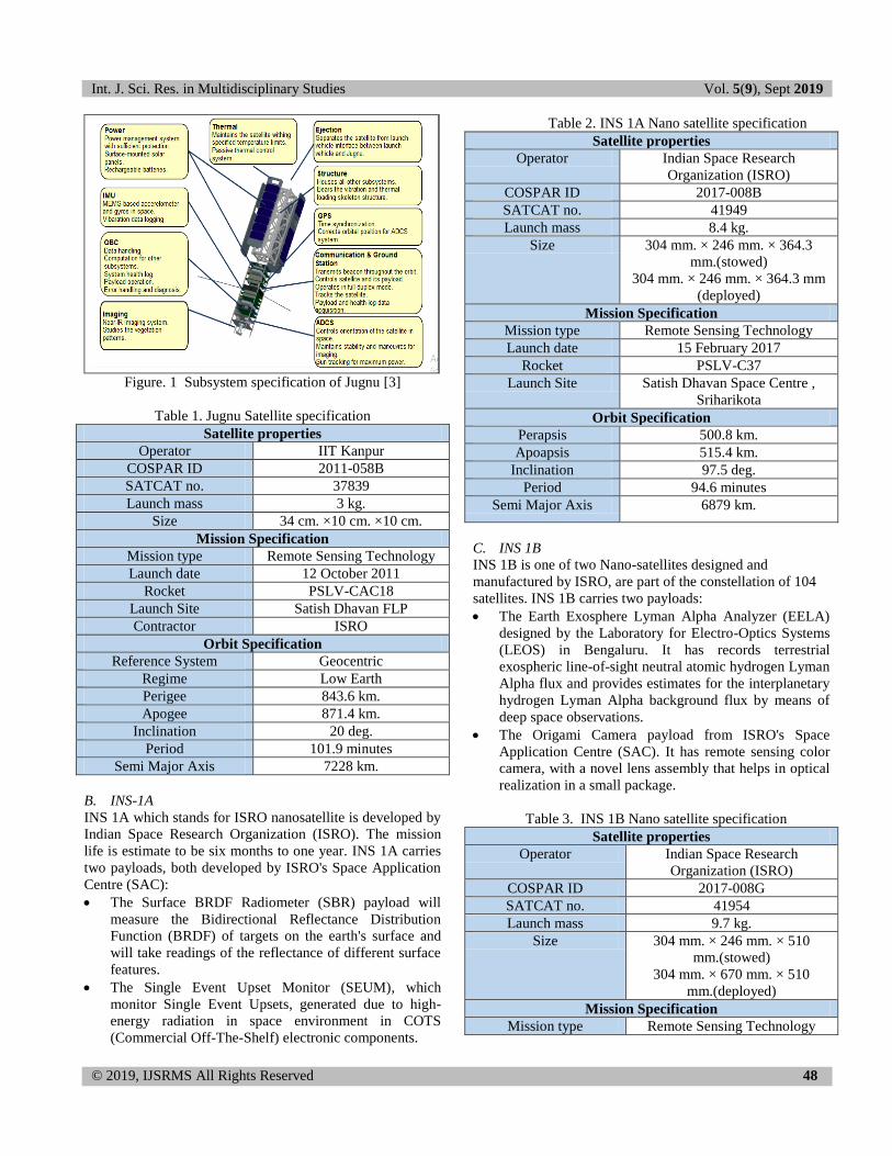
A. CubeSat Jugnu
The specification of the Nano satellites selected for purpose
of research as given below-
A Nano Satellite is an artificial satellite characterized by its
low weight, small size and its miniaturization to save cos. It
has requires for cheaper launch vehicles and can be launched
in multiple. The Nano satellites not only serve the purpose of
communication, remote sensing and space science
applications. It playing a vital role in the technical
knowledge development by providing a means for direct,
hands-on experience in all stages and aspects of a real
satellite mission. [1] [2]. Jugnu has built, under the
supervision of Dr. N. S. Vyas, which is capable to provide
information on agriculture and disaster monitoring.
Int. J. Sci. Res. in Multidisciplinary Studies Vol. 5(9), Sept 2019
© 2019, IJSRMS All Rights Reserved 48
Figure. 1 Subsystem specification of Jugnu [3]
Table 1. Jugnu Satellite specification
Satellite properties
Operator IIT Kanpur
COSPAR ID 2011-058B
SATCAT no. 37839
Launch mass 3 kg.
Size 34 cm. ×10 cm. ×10 cm.
Mission Specification
Mission type Remote Sensing Technology
Launch date 12 October 2011
Rocket PSLV-CAC18
Launch Site Satish Dhavan FLP
Contractor ISRO
Orbit Specification
Reference System Geocentric
Regime Low Earth
Perigee 843.6 km.
Apogee 871.4 km.
Inclination 20 deg.
Period 101.9 minutes
Semi Major Axis 7228 km.
B. INS-1A
INS 1A which stands for ISRO nanosatellite is developed by
Indian Space Research Organization (ISRO). The mission
life is estimate to be six months to one year. INS 1A carries
two payloads, both developed by ISRO's Space Application
Centre (SAC):
The Surface BRDF Radiometer (SBR) payload will
measure the Bidirectional Reflectance Distribution
Function (BRDF) of targets on the earth's surface and
will take readings of the reflectance of different surface
features.
The Single Event Upset Monitor (SEUM), which
monitor Single Event Upsets, generated due to high-
energy radiation in space environment in COTS
(Commercial Off-The-Shelf) electronic components.
Table 2. INS 1A Nano satellite specification
Satellite properties
Operator Indian Space Research
Organization (ISRO)
COSPAR ID 2017-008B
SATCAT no. 41949
Launch mass 8.4 kg.
Size 304 mm. × 246 mm. × 364.3
mm.(stowed)
304 mm. × 246 mm. × 364.3 mm
(deployed)
Mission Specification
Mission type Remote Sensing Technology
Launch date 15 February 2017
Rocket PSLV-C37
Launch Site Satish Dhavan Space Centre ,
Sriharikota
Orbit Specification
Perapsis 500.8 km.
Apoapsis 515.4 km.
Inclination 97.5 deg.
Period 94.6 minutes
Semi Major Axis 6879 km.
C. INS 1B
INS 1B is one of two Nano-satellites designed and
manufactured by ISRO, are part of the constellation of 104
satellites. INS 1B carries two payloads:
The Earth Exosphere Lyman Alpha Analyzer (EELA)
designed by the Laboratory for Electro-Optics Systems
(LEOS) in Bengaluru. It has records terrestrial
exospheric line-of-sight neutral atomic hydrogen Lyman
Alpha flux and provides estimates for the interplanetary
hydrogen Lyman Alpha background flux by means of
deep space observations.
The Origami Camera payload from ISRO's Space
Application Centre (SAC). It has remote sensing color
camera, with a novel lens assembly that helps in optical
realization in a small package.
Table 3. INS 1B Nano satellite specification
Satellite properties
Operator Indian Space Research
Organization (ISRO)
COSPAR ID 2017-008G
SATCAT no. 41954
Launch mass 9.7 kg.
Size 304 mm. × 246 mm. × 510
mm.(stowed)
304 mm. × 670 mm. × 510
mm.(deployed)
Mission Specification
Mission type Remote Sensing Technology
Int. J. Sci. Res. in Multidisciplinary Studies Vol. 5(9), Sept 2019
© 2019, IJSRMS All Rights Reserved 49
Launch date 15 February 2017
Rocket PSLV-C37
Launch Site Satish Dhavan Space Centre ,
Sriharikota
Orbit Specification
Perapsis 500.7 km.
Apoapsis 514.8 km.
Inclination 97.5 deg.
Period 94.6 minutes
Semi Major Axis 6878 km.
II. LITERATURE REVIEW
Orbit Design and simulation for Kufasat Nano satellite; a
research paper by Mohammed Chessab Mahdi of Al-Furat
Al-Awsat Technical University explains the detail orbit
design using GMAT and Matlab. The satellite is design for
Sun synchronous orbit with payload for image purpose. [3]
Trajectory design tools for liberation and cislunar
environment; a conference paper presented in 6th
International Conference on Astrodynamics tools and
techniques on 16th
March 2016 [4] [5] talks about the
innovative trajectory design tools Adaptive Trajectory
design and GMAT which has the ability to design multibody
trajectory. The paper also provides solution to simplify
trajectory design in support of lunar and liberation point.
The computation of satellite orbit trajectory; from Elsevier,
Advances in computer, Volume 3 [6] focuses on
computation of satellite orbit trajectory, orbit determination
and tracking. Three mathematical formulation Cowells and
Encke‟s methods are described the variation of parameters
evaluated for computational efficiency. The deliberation
theory is mainly to discuss general perturbation method.
Precise orbit determination of low earth satellite at AIUB
using GPS and SLR data; by A. Jaggi, H. Bock, D. Thaller,
K. So´snica, U. Meyer , C. Baumann , and R. Dach
presented in ESA Living Planet Symposium [7]. Explains
the classical numerical integration techniques used for
dynamic orbit determination of satellites operating at high
altitudes which is further extended by pseudo-stochastic
orbit modelling techniques to efficiently cope with potential
force model deficiencies for satellites at low altitudes.
Trajectory design for the transiting exoplanet survey
satellite; a paper by Donald J. Dichmann, Joel J.K. Parker,
Trevor W. Williams, Chad R. Mendelsohn presented in
AIAA/AAS Astrodynamics Specialist Conference [8]
Discusses the adaption of the schematic window
methodology (SMW76) is used to assess the TESS mission
constraint. Employment of Dynamical system theory in the
circular restricted 3 body problem (CR3BP) which makes
use of high-fidelity model and multiple shooting in GMAT
to optimize the manoeuvre delta „v‟ and mission constraint.
Orbit design and trajectory analysis for University Cube-
Satellite project for remote sensing and for educational
application; a conference paper from Global Space
Exploration Conference Washington, DC. B by Ugur Guven,
Gurunadh Velidi, Samaksh Behl [9] in which an optimal
near polar, low earth orbit is calculated for the Nano satellite
under study along with its structural configurations. The
cubesat is design for different attitude adjustments systems
explored in order to create the most stable configuration in
orbit. The mission of this Nano satellite is remote sensing
and for educational purposes such as seismic activity
determination.[10]
The paper uses the following formulae and equations:[11]
1. The square of the orbital period of a planet is
proportional to the cube of the semi-major axis of
its orbit.
(1)
2. Semi Major Axis (a): It gives the size of the orbit
and is the distance between apogee and perigee
divided by 2.
(2)
Where P is the orbital period, G is the gravitational constant;
M is the combined mass of primary and secondary orbits.
3. Eccentricity (e): It gives the shape of the orbit. Its
value ranges from 0 when the orbit is perfect circle
to 1 when it is flat.
(3)
Where v is orbital speed, h is angular momentum vector, μ is
standard gravitational parameter, and r is orbit radius.
4. Inclination angle (I): It defines the orientation of
the orbit with respect to the Earth‟s equator. It is the
angle between Z and angular momentum h. The
inclination ranges from 0 to 180. Degrees.
(4)
5. Right Ascension of Ascending Node (Ω): It is the
angle from the vernal equinox to the ascending
node. The ascending node is the point where the
satellite passes through the equatorial plane moving
from south to north. Right ascension is measured as
a right-handed rotation about the pole Z.
(5)
If Ω
6. Argument of Perigee (w): It gives the angle from
the ascending node to the eccentricity vector,
measured in the direction of the satellite‟s motion.
The eccentricity vector points from the center of the

Int. J. Sci. Res. in Multidisciplinary Studies Vol. 5(9), Sept 2019
© 2019, IJSRMS All Rights Reserved 50
Earth to perigee with a magnitude equal to the
eccentricity of the orbit.
(6)
If
Where:
is a vector pointing towards the ascending node
(i.e. the z-component of n is zero)
is the eccentricity vector (a vector pointing
towards the perigee)
7. True mean anomaly (M): It gives the fraction of
an orbit period that has elapsed since perigee,
expressed as an angle. The mean anomaly equals
the true anomaly for a circular orbit.
(7)
If
M = E-e sin (E)
Where E is eccentric anomaly.[12]
III. METHODOLOGY (GLOBAL MISSION
ANALYSIS TOOL- GMAT)
GMAT is an open source trajectory design and optimization
system developed by NASA and private Industry. An open
source system mainly used to maximize the technology
transfer and allow anyone to develop and validate new
algorithms. GMAT is design the model and optimize
spacecraft trajectories in flight regimes ranging from Low
Earth orbit to lunar applications, interplanetary trajectories,
and other deep space missions. The system supports
constrained and unconstrained trajectory optimization, built-
in features, make defining cost, and constraint functions
trivial, so analysts can determine how their inclusion or
exclusion effects solutions.
Figure 2. Signal flow diagram (GMAT)
The following flow chart depicts the process of obtaining
results from GMAT:
Figure 3. Flowchart for the adopted methodology for
simulating the orbits
From Fig. 3 shows the methodology for Nano satellites
Jugnu, INS 1A, INS 1B simulating the orbits. The first step
for the project is to select three different satellites and
determine their position in the Low Earth Orbit by obtaining
the orbital elements for each satellite respectively. The
second step is to design the accurate orbit and trajectory of
the satellites by acquiring the data regarding the various
factors affecting the position of satellite in space using
GMAT, Orbitron and STK simulation software and
implementing the same acquired data for MATLAB
interface. To find the deflection in the satellites from their
orbit due to perturbations and attempt to provide a high
accuracy method for the correction of the same. After
applying this process, two different types of views namely:
1. Orbit View: This is a 3D view of orbit of satellite
traversing around Earth. This view makes analysis of
satellite easier as you can rotate and zoom in/out to
locate the satellite. The below picture shows an example
of Orbit View:

Int. J. Sci. Res. in Multidisciplinary Studies Vol. 5(9), Sept 2019
© 2019, IJSRMS All Rights Reserved 51
Figure 4. Satellite Orbit View
Figure 5. 2D Plot view for a satellite in GMAT
2. 2D View or Ground View: This view shows the ground
track obtained for the computed Keplerian element
which is simulated in GMAT, below figure shows a
ground track of KufaSat projected onto a two-
dimensional world map over one day:
A. ORBITRON
Orbitron is a one of the basic satellite tracking system. This
platform provides information essential UFO hobbyists.
Application shows the positions of satellites at any given
moment (in real or simulated time). Due to predictable
conditions of satellite movement in space, (lack of
atmosphere) computer software can calculate a satellite's
position for given moment.
The calculations based on known orbit parameters
determined of the related satellite. The six Keplerian
elements also known as orbital parameters like inclination,
eccentricity, argument of perigee, mean motion (revolutions
per day), tracks satellite for a reasonable period after epoch.
Orbital data for each object is grouped and distributed as a
Two-Line Element (TLE) file. The TLE file used to get the
parameters of the satellite in the software so that it tracks
and determines its orbit path.
Below Fig. 6. illustrate a generalised view of Orbitron:
Figure 6. GUI of Orbitron
B. Satellite Tool Kit (STK)
STK is an orbit simulation software that provides four-
dimensional modelling, simulation, and analysis of objects
from land, sea, air, and space in order to evaluate system
performance in real or simulated-time. This platform is
capable of modelling an accurate Earth representation in
time and space and can Run in real time or simulate in past
or future time.
IV. SIMULATION RESULTS
In Fig. 7. Shows the GUI information of Satellite Tool Kit
Figure 7. GUI of System Tool Kit
Int. J. Sci. Res. in Multidisciplinary Studies Vol. 5(9), Sept 2019
© 2019, IJSRMS All Rights Reserved 52
STK SIMULATION
From Fig.8. Shows the orbit path of Jugnu Nano satellites
satellite from space on a 2D view. The orbital parameters are
mention in the solver.
Figure 8. Orbit of Jugnu Nano satellite
Figure 9. Orbit of INS 1A Nano satellite
Figure 10. Orbit of INS 1B Nano satellite
From Fig.9 & 10. Shows the orbit path of INS 1A & INS 1B
Nano satellites satellite from space on a 2D view. The orbital
parameters are mention in the solver.
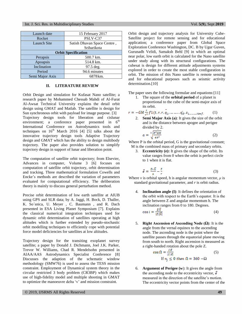
ORBITRON SIMULATION
Orbitron is a simple 2D solver in which TLE files are
uploaded, for Jugnu, INS 1A & INS 1B satellite shown in
the figure (11 & 12 & 13)TLE file for JUGNU is available
in Directories of NASA and NORAD.
Figure 11. Orbit simulation of Jugnu performed on Orbitron
Figure 12. Orbit simulation of INS-1A performed on Orbitron
Figure 13. Orbit simulation of INS-1B performed on Orbitron
GMAT SIMULATION
GMAT solves or designs the orbit of Jugnu satellite through
six Keplerian elements with different orbit view shown from
Figure 14 & 15.The 2D view illustrate in the Figure 16.
Figure 14. Satellite Orbit View 1 (GMAT)

Int. J. Sci. Res. in Multidisciplinary Studies Vol. 5(9), Sept 2019
© 2019, IJSRMS All Rights Reserved 53
Figure 15. Satellite Orbit View 2 (GMAT)
2D plot view of Jugnu satellite as shown below
Figure 16. 2D view of Orbit on GMAT
V. CONCLUSION
Nano satellite or cube satellite technology is gradually
emerging as an important technology in space industry over
the last two decades. The space emerging countries and non-
space countries are now in a race to operate small satellite
mission. It is becoming popular among developing countries
because of cost effective programme with great capability.
The small satellite in space activity is extending the number
of satellites for specific designed mission both for civilian
and defence purpose. So, the number of associated launches,
ground station and data collection and distribution system
are getting more importance than ever. That is why the
demand of LEO satellite tracking system for data collection
and distribution is increasing.
The three Nano satellite chosen, each serve different
research purpose is launch by Indian Space Research
Organization (ISRO). Jugnu is built under the supervision of
Dr. N. S. Vyas, which is capable to provide information on
agriculture and disaster monitoring. INS-1A and INS-1B,
which stands for ISRO nanosatellite, are part of the
constellation of 104 satellites is developed by ISRO. The
coordinates and satellite orbit trajectory were determined,
and the orbit has been analyzed using three software‟s
namely GMAT, STK and Orbitron and the differences in the
orbit scenario. The project is analyses the orbits of three
satellites in total and compare with the respective software‟s
along with a MATLAB software interfacing of the data
acquired.
REFERENCES
[1] Perry, W.R. "Orbital Mechanics". In Theodore Baumeister. Marks'
Standard Handbook for Mechanical Engineers (Seventh Ed.). New York City: McGraw Hill. pp. 11:151–52. ISBN 0-07-142867-4, 1967
[2] H. D. Curtis, Orbital Mechanics for Engineering Students, Florida:
Elsevier Butterworth-Heinemann publications, 2005.
[3] Ugur Guven, "Orbit Design And Trajectory Analysis For University
Cube-Satellite Project For Remote Sensing And For Educational
Applications," in Global Space Exploration Conference , Washington, DC.
[4] Mohammed Chessab Mahdi, “Orbit Design and Simulation for Kufasat
Nanosatellite”, Journal of Artificial Satellites, Vol. 50, No. 4, 2015 Doi: 10.1515/arsa-2015-0013.
[5] WH Steyn, “Comparison of Low-Earth Orbiting Satellite Attitude Controllers Submitted to Controllability Constraints”, AIAA Journal of
Guidance, Control, and Dynamics, Vol.17, No.4, July-Aug.1994,
pp.795-804
[6] Kristin Johansson, “Orbital Mechanics and Feedback Control”, Master
Thesis, Department of Engineering Cybernetics, Norwegian University
of Science and Technology, Trondheim, June 15, 2005
[7] George A. Weisskopf, “Application and Analysis of Satellite Orbit
Prediction Techniques”, Mission Planning and Analysis Division
National Aeronautics and Space Administration, Johnson Space Center Houston, Texas, JSC Internal note no. 77-Fm-19, April 12, 1977
[8] S. P. Shuster, "A Survey and Performance Analysis of Orbit
Propagators for LEO, GEO, and Highly Elliptical Orbits," All Graduate Theses and Dissertations, Utah, 2017
[9] Kim, S., and Kim, Y., “Spin-Axis Stabilization of a Rigid Spacecraft
using two Reaction Wheels,” Journal of Guidance, Control, and Dynamics, Vol. 24, No. 5, 2001, pp. 1046–1049.doi:10.2514/2.4818
[10] S. Alam and M. Yasir, "Satellite Attitude and Orbital Dynamics
Simulator," Journal of Space Technology, Vol. 1, No. 1, PP. 40-44,
2011
[11] Schaub, H., and Junkins, J. L., “MATLAB Toolbox for Rigid Body
Kinematics” Proceedings of the AAS/AIAA Space Flight Mechanics Meeting, Breckenridge, CO, American Astronautical Soc. Paper 99-
139, Springfield, VA, 7–10 Feb. 1999, pp. 549–560.
[12] Karataş S, (2006) “LEO Satellites: Dynamic Modelling, Simulations and some Nonlinear Attitude Control Techniques” Master Thesis,
Middle East Technical University, The Graduate School of Natural and
Applied Sciences, Electrical and Electronics Engineering, April 2006.


![Thermal conductivity calculation of nano-suspensions using ... · higher thermal conductivity [, 13]. Conversely, fluctua8 - tions lose correlation quickly in amorphous materials](https://img.dokumen.tips/doc/110x75/609eca91fefaf146452d4d31/thermal-conductivity-calculation-of-nano-suspensions-using-higher-thermal-conductivity.jpg)