Embed Size (px)
Citation preview

IJSRD - International Journal for Scientific Research & Development| Vol. 4, Issue 08, 2016 | ISSN (online): 2321-0613
All rights reserved by www.ijsrd.com 27
Design and Analysis of Tractor Trolley Axle
Sunil Ravindra Patil1 Prof. P. D. Kulkarni2
1,2Department of Mechanical Engineering 1,2Sinhgad Institute of Technology, Lonavala
Abstract— In India, Tractor trolley plays an important role
in agriculture and construction field for the transportation.
Many small industries are involved in the manufacturing of
the Tractor trolley. Due to lack of the advance technologies,
this product may not properly design. The tractor trolley is
designed as per the requirement or by trial and error method
of manufacturing. Many times it may be designed without
considering the actual loading condition. There are some
rules and regulations for the tractor trolley or trailer. The
tractor trolley should be as per the Indian Standard
specification IS 8213:2000. Many small industries not
follow the Indian Standards Specifications Central Motor
Vehicles Act, 1988 and safety standard (SS-15) of
Automotive Research Association of India. Many road
accidents and breakdown or failures occurs due to poor
design of the tractor trolley, In present work analytical and
finite element analysis approach is used to design the tractor
trolley for safe working condition. Need to consider the
stress concentration, weight and cost reduction of existing
trolley axle. Both the factors are related to each other. In this
project, we will do the design related work in CATIA V5
R24 and the analysis work in the ANSYS 15.0 Software.
Static analysis i.e. analytical method required for this to
compare the ANSYS results. From the comparison reports
we will suggest the best possible solution for the Tractor
Trolley.
Key words: CATIA V5 R24, ANSYS 15.0, Weight
Reduction, Cost Reduction, Trolley axle
I. INTRODUCTION
Nowadays, quality of the product within the lowest cost
plays an important role in the product manufacturing
industries. Weight reduction and optimized design are the
application of industrial engineering. Tractor trolleys are
mostly manufactured in small scale industries such as
farming machinery, thrashers, tractor trolleys etc.
Building construction material, Industrial
equipment and agriculture product transporting are done by
tractor trolleys. Robust construction, longer working life and
easy maintain and high performance are the main criteria of
trolley manufacturing. Tractor trolleys are available in
single axle and double axle. Single axle trolleys are
available in 3 ton and 5-ton capacity. Above 5-ton capacity
double axle trolleys are suitable. The figure below shows the
dummy model of existing tractor Trolley. A trolley is one of
the standard sizes of the trolley which is generally designed
for 8 tons capacity. The aim of this project is to design and
analysis this standard a size of trolley for the critical loading
condition i.e. for 15 tons and at critical road condition.
Trolley has been designed for high load carrying capacity.
While designing trolley main focus was on the weight of the
trolley because for robust design if weight will be increased
cost will increase for the trolley.
Fig. 1: Dummy Tractor Model
A. Objectives
Getting the benchmark data of Trolleys available in
the market and design the Tractor Trolley for the
15 tons capacity.
Designing of Axle and Chassis of the trolley such
that it will be strong enough to sustain the
maximum loading conditions on the Indian roads.
Cost Reduction and Weight Reduction of the
Tractor Trolley, by changing the shape and
material of the Axle and Chassis.
To develop a new tractor trolley axle and chassis.
So, we need to develop the trolley parts so that quality of the
parts should be good considering the cost and weight of the
complete assembly. Some points are highlighted as below.
1) Strength analysis of trolley assembly will be
carried out at different load conditions considering
critical load conditions.
2) Design optimization study will be carried out by
studying highly stress concentrated area.
3) Weight and Cost optimization will be done on
trolley parts.
II. DESIGN AND DEVELOPMENT OF TRACTOR TROLLEY AXLE
A. Types of Tractor Trolley:-
The agricultural trailers shall be of following two types:
a) Balanced trailer (double axel) and
b) Semi-trailer (single axle).
Both the types of trailers may be fitted with fixed or tipping
platform.
B. Capacity:-
1) The capacity of a trailer shall be its gross load and
shall be 2, 3, 4, 5, 6, 8 and 10 tons. The gross load
along with the payload shall be declared by the
manufacturer. The declared capacity shall not vary
by + or - 5 percent.
2) The capacity of the single-axle trailers shall be not
more than 5 tons.

Design and Analysis of Tractor Trolley Axle
(IJSRD/Vol. 4/Issue 08/2016/006)
All rights reserved by www.ijsrd.com 28
3) Tractor operated trailers are used for transport of
farm produce. This standard has been prepared for
the guidance of manufacturers and purchasers in
the production and selection of trailers of proper
quality.
Considering the 8 tons trolley we need to design the double
axel tractor trolley.
Double Axle, 4-wheeler box type trolley
Overall
Dimensions
Overall Length
5010 mm (Trolley
Box)
6050 mm ( Chassis )
Overall Width 1955 mm (Trolley
Box)
Overall Height 1745 mm above
ground
Load
Capacity
Pay Load 8000 kg
Unloaded Weight 2000 kg
Gross load Weight 10000 kg
Axle Two square axle are used presently 80×80
mm square of length 1900 m.
Table 1: General Specification of Original Tractor Trolley
All dimensions are in mm.
Fig. 2: Single Axle Tractor Trolley Dimensions
All dimensions are in mm.
Fig. 3: Double Axle Tractor Trolley Dimensions
C. Materials and Methods:-
In our project work, finite element analysis approach will be
used (by considering change in materials and change in
existing shape and size). A CAD model of existing trolley
axle is prepared by using CATIA V5 software then the
analysis is done with the help of ANSYS.
D. Material Selection:-
So for better design and reduce the cost of material we
compare the three materials
SAE-1020,
SAE 1040,
Ductile Cast Iron 80-55-06.
Material S. A. E.
1020
S. A. E.
1040
D.C.I.
80-55-06
Ultimate
Strength
(N/mm2)
420 595 559
Yield Strength
(N/mm2) 370 515 370
Density (Kg/m³) 7870 7845 7150
E (N/mm2) 205000 200000 168000
Poisson Ratio 0.29 0.29 0.31
Cost Per Kg
(Rs.) 40.75 45.75 64.5
Table 2: Material Properties
E. Design of Existing Axle:-
Fig. 4: Existing Axle
In our project work, analytical analysis approach is used,
(By considering the change in materials and change in
existing shape and size). An existing trolley axle is
redesigned for the given load condition, then check the
actual deflection occurred in existing axle, also, different
material and different shape axle get the design, Select the
best axle according to the condition. The main purpose of
the project is to make a safer working condition of trolley
axle as well as for stress concentration, weight and cost
reduction.
F. Load Conditions:-
As we know that the dynamic load is always more than
static load but it is not possible to define the accurate
dynamic load, so we consider as a maximum load due to
dynamic loading is 37.5 KN on each leaf spring.
Fig. 5: Load Distribution Diagram
Let RA and RB be the reactions at the supports A and B
respectively.
Load Point Shear Force
KN
Bending Moment
KNmm
A 37.75 0
C 0.25 8795.75
D -0.25 8918.75
E -37.75 8795.75
B 0 0
Table 3: Shear Force and Bending Moment on Axle
7. Design:-
Design and Analysis of Tractor Trolley Axle
(IJSRD/Vol. 4/Issue 08/2016/006)
All rights reserved by www.ijsrd.com 29
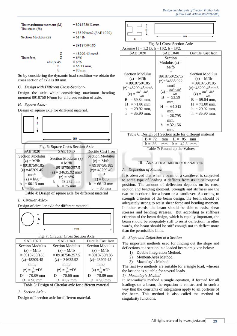
So by considering the dynamic load condition we obtain the
cross section of axle is 80 mm.
G. Design with Different Cross-Section:-
Design the axle while considering maximum bending
moment 8918750 N/mm for all cross section of axle.
H. Square Axle:-
Design of square axle for different material.
Fig. 6: Square Cross Section Axle
SAE 1020 SAE 1040 Ductile Cast Iron
Section Modulus
(z) = M/fb
= 8918750/185
(z) =48209.45
mm³
(z) = b³/6
b = 66.13 mm
b = 80 mm
Section Modulus (z)
= M/fb
= 8918750/257.5
(z) = 34635.92 mm³
(z) = b³/6
b = 59.232 mm
b = 75 mm
Section Modulus
(z) = M/fb
= 8918750/185
(z)= 48209.45
mm³
(z) = b³/6
b = 66.13 mm
b = 80 mm
Table 4: Design of square axle for different material
I. Circular Axle:-
Design of circular axle for different material.
Fig. 7: Circular Cross Section Axle
SAE 1020 SAE 1040 Ductile Cast Iron
Section Modulus
(z) = M/fb
= 8918750/185
(z)=48209.45
mm3
(z) = 1
32𝜋D³
D = 78.89 mm
D = 90 mm
Section Modulus
(z) = M/fb
= 8918750/257.5
(z) = 34635.92
mm3
(z) = 1
32𝜋D³
D = 70.66 mm
D = 82 mm
Section Modulus
(z) = M/fb
= 8918750/185
(z)=48209.45
mm3
(z) =1
32𝜋D³
D = 78.89 mm
D = 90 mm
Table 5: Design of Circular axle for different material
J. Section Axle:-
Design of I section axle for different material.
Fig. 8: I Cross Section Axle
Assume H = 1.2 B, h = H/2, b = B/2.
SAE 1020 SAE 1040 Ductile Cast Iron
Section Modulus
(z) = M/fb
= 8918750/185
(z)=48209.45mm3
(z) = 𝐵𝐻³−𝑏ℎ³
6𝐻
B = 59.84 mm,
H = 71.80 mm
b = 29.92 mm,
h = 35.90 mm.
Section
Modulus (z) =
M/fb
=
8918750/257.5
(z)=34635.922
mm3
(z) = 𝐵𝐻³−𝑏ℎ³
6𝐻
B = 53.59
mm,
H = 64.312
mm,
b = 26.795
mm,
h = 32.156
mm.
Section Modulus
(z) = M/fb
= 8918750/185
(z)=48209.45mm3
(z) = 𝐵𝐻³−𝑏ℎ³
6𝐻
B = 59.84 mm,
H = 71.80 mm,
b = 29.92 mm,
h = 35.90 mm.
Table 6: Design of I Section axle for different material
B = 72 mm H = 85 mm
b = 36 mm h = 42.5 mm
Table 7: Round up the Values
III. ANALYTICAL METHOD OF ANALYSIS
A. Deflection of Beams:-
It is observed that when a beam or a cantilever is subjected
to some type of loading it deflects from its initial/original
position. The amount of deflection depends on its cross
section and bending moment. Strength and stiffness are the
two main criteria for a beam or a cantilever. According to
strength criterion of the beam design, the beam should be
adequately strong to resist shear force and bending moment.
In other words, the beam should be able to resist shear
stresses and bending stresses. But according to stiffness
criterion of the beam design, which is equally important, the
beam should be adequately stiff to resist deflection. In other
words, the beam should be stiff enough not to deflect more
than the permissible limit.
B. Slope and Deflection at a Section
The important methods used for finding out the slope and
deflections at a section in a loaded beam are given below:
1) Double Integration Method.
2) Moment-Area Method.
3) Macaulay’s Method.
The first two methods are suitable for a single load, whereas
the last one is suitable for several loads.
1) Macaulay’s Method
In Macaulay’s method a single equation, if formed for all
loadings on a beam, the equation is constructed in such a
way that the constants of integration apply to all portions of
the beam. This method is also called the method of
singularity functions.

Design and Analysis of Tractor Trolley Axle
(IJSRD/Vol. 4/Issue 08/2016/006)
All rights reserved by www.ijsrd.com 30
This is a convenient method for determining the
deflection of a beam subjected to point loads or in general
discontinuous loads.
When the load on a beam does not conform to
standard cases, the solution for slope and deflection must be
found from first principles. Macaulay developed a method
for making the integration simpler.
The basic equation governing the slope and
deflection of beams is
EI𝑑²𝑦
𝑑𝑥² = M
Where, M is a function of x.
When a beam has a variety of loads it is difficult to
apply this theory because some loads may be within the
limits of x during the derivation but not during the solution
at a particular point. Macaulay’s method makes it possible
to do the integration necessary by placing all the terms
containing x within a square bracket and integrating the
bracket, not x. During the evaluation, any bracket with a
negative value is ignored because a negative value means
that the load it refers to is not within the limit of x. the
general method of solution is conducted as follows. Refer to
figure given below. In the real example, the loads and
reactions would have numerical values numerical values but
for the sake of demonstrating the general method, we will
use algebraic symbols. This example has only point loads.
Fig. 9: Loading Condition
1) Write down the bending moment equation placing x on
the extreme right-hand end of the beam so that it
contains all the loads. Write all terms containing x in a
square bracket.
cxFbxFaxFxRMdx
ydEI
32112
2
2) Integrate once treating the square bracket as the
variable.
A
cxF
bxF
axF
xRM
dx
dyEI
2
3
2
2
2
1
2
12222
3) Integrate again using the same rules.
BAx
cxF
bxF
axF
xRMEIy
3
3
3
2
3
1
3
16666
4) Use boundary conditions to solve A and B.
5) Solve slope and deflection by putting in appropriate
value of x. Ignore and brackets containing negative
values.
1. In the case of a fixed beam, there are four unknowns:
RA, RB, MA and MB. Thus, the two statics equations must
be supplemented by two additional equations arising
from deformations.
For the same spans and loads, the fixed beams claim the
following advantages over simply supported beams.
1. These have lesser values for maximum bending
moments.
2. These have lesser values for maximum deflection.
IV. FINITE ELEMENT ANALYSIS
The finite element method is a numerical method for solving
problems of engineering and mathematical physics. Typical
problem areas of interest in engineering and mathematical
physics that are solvable by use of the finite element method
include structural analysis, heat transfer, fluid flow, mass
transport, and electromagnetic potential. For problems
involving complicated geometries, loadings, and material
properties, it is generally not possible to obtain analytical
mathematical solutions. Analytical solutions are those given
by a mathematical expression that yields the values of the
desired unknown quantities at any location in a body (here
total structure or physical system of interest) and is thus
valid for an infinite number of locations in the body. These
analytical solutions generally require the solution of
ordinary or partial differential equations, which, because of
the complicated geometries, loadings, and material
properties, are not usually obtainable. Hence, we need to
rely on numerical methods, such as the finite element
method, for acceptable solutions. The finite element
formulation of the problem results in a system of
simultaneous algebraic equations for the solution, rather
than requiring the solution of differential equations. These
numerical methods yield approximate values of the
unknowns at discrete numbers of points in the continuum.
Hence, this process of modeling a body by dividing it into
an equivalent system of smaller bodies or units (finite
elements) interconnected at points common to two or more
elements (nodal points or nodes) and/or boundary lines
and/or surfaces is called discretization. In the finite element
method, instead of solving the problem for the entire body in
one operation, we formulate the equations for each finite
element and combine them to obtain the solution of the
whole body.
A. For Material SAE 1020:-
For Existing Square Axle (100×100)
1) Deflection Report
Fig. 10: Deflection Report for Existing Square Axle

Design and Analysis of Tractor Trolley Axle
(IJSRD/Vol. 4/Issue 08/2016/006)
All rights reserved by www.ijsrd.com 31
2) Stress Report
Fig. 11: Stress Report for Existing Square Axle
B. For Material SAE 1020:-
For Square Axle (80×80)
1) Deflection Report
Fig. 12: Deflection Report for Square Axle (80 * 80)
2) Stress Report
Fig. 13: Stress Report for Square Axle (80 * 80)
C. For Material SAE 1020:-
For Circular Axle Dia. 80
1) Deflection Report
Fig. 14: Deflection Report for Circular Axle Dia. 90
2) Stress Report
Fig. 15: Stress Report for Circular Axle Dia. 90
D. For Material SAE 1020:-
For I Section
1) Deflection Report
Fig. 16: Deflection Report for I-Section Axle
2) Stress Report
Fig. 17: Stress Report for I-Section Axle
E. For Material SAE 1040:-
For Square Axle (75×75)
1) Deflection Report
Fig. 18: Deflection Report for Square Axle (75*75)

Design and Analysis of Tractor Trolley Axle
(IJSRD/Vol. 4/Issue 08/2016/006)
All rights reserved by www.ijsrd.com 32
2) Stress Report
Fig. 19: Stress Report for Square Axle (75*75)
F. For Material SAE 1040:-
For Circular Axle Dia. 82mm
1) Deflection Report
Fig. 20: Deflection Report for Circular Axle (82*82)
2) Stress Report
Fig. 21: Stress Report for Circular Axle (82*82)
G. For Material SAE 1040:-
For I Section Axle
1) Deflection Report
Fig. 22: Deflection Report for I-Section Axle
2) Stress Report
Fig. 23: Stress Report for I-Section Axle
H. For Ductile Cast Iron (80-55-06) Material:-
For Square Axle (80×80)
1) Deflection Report
Fig. 24: Deflection Report for Square Axle
2) Stress Report
Fig. 25: Stress Report for Square Axle
I. For Ductile Cast Iron (80-55-06) Material:-
For Circular Axle
1) Deflection Report
Fig. 26: Deflection Report for Circular Axle

Design and Analysis of Tractor Trolley Axle
(IJSRD/Vol. 4/Issue 08/2016/006)
All rights reserved by www.ijsrd.com 33
2) Stress Report
Fig. 27: Stress Report for Circular Axle
J. For Ductile Cast Iron (80-55-06) Material:-
For I Section Axle
1) Deflection Report
Fig. 28: Deflection Report for I-Section Axle
2) Stress Report
Fig. 29: Stress Report for I-Section Axle
Materi
al Shape
Maximu
m
Stresses
(N/mm²)
Deflecti
on
(mm)
Mass of
Axle(K
g)
Price/Pie
ce
(Rs.)
SAE
1020
SQUAR
E
(Existin
g Axle)
44.02 0.160 130.26 5308.10
SAE
1020
Square 85.92 0.391 88.64 3612.08
Round 102.44 0.414 88.198 3594.06
I-
Section 90.20 0.386 67.715 2759.386
SAE
1040
Square 104.275 0.518 79.427 3633.785
Round 134.5 0.616 75.463 3452.432
I-
Section 111.08 0.518 60.24 2755.98
Ductil
e Cast
Iron
Square 85.92 0.477 80.531 5194.25
Round 102.45 0.505 80.129 5168.32
I-
Section 90.20 0.471 61.52 3968.04
Table 3: Comparison of stresses and price for different cross
section axle
K. Cost Reduction
When we consider the different c/s of the axle with the
different material then we got minimum weight of axle
60.24 Kg. For I-section and material is SAE 1040 iron with
the price of 2755.98 Rs. But I section is not uniform
throughout; we need the circular section at the ends for the
rim attachment. We need to weld the circular ends to the
axle. Weld is not as strong as the uniform material part. So,
we have to avoid the welding and I section for the axle. In
this case we need to consider the deflection of the axle at the
center. The minimum deflection is 0.391 mm. Also the
stress is minimum 85.92 N/mm². As the material cost is less.
We will go for the SAE 1020 modified square section axle.
From the safety point of view we will use SAE 1020
modified square section axle.
Compare the Existing Axle Price and New Designed Axle
Minimum Price
Existing axle price is 5308.10 Rs.
New designed axle minimum price is 3612.08 Rs.
So we got the price difference of 1696.02 Rs.
Means by adopting the new design of axle we can reduce the
axle cost up to 1696.02 Rs.
V. CONCLUSION
This study was conducted on an existing rear axle shaft used
in tractor trolley shows that the existing axle has greater
factor of safety so un-wontedly heavy axle is used for trolley
in existing condition which increases the weight of axle as
well as cost of axle. But the newly designed axle with
different cross section and different material show that we
can maximally reduce the 31.95 % weight as compared to
the existing axle shown in comparison table. Also reduces
the cost of trolley axle as the weight of the axle reduces. We
reduce the cost of axle approximately up to 1696 Rs. per
axle and the deformations, as well as stresses developed in
newly designed axle are in within limits.
REFERENCES
[1] Vinayak R. Tayade (2015), “Experimental Analysis of
Tractor Trolley Chassis”, International Journal of
Engineering Sciences and Research Technology, ISSN:
2277-9655.
[2] Kshitija A. Bhat1 and Harish V. Katore (2014), “The
Failure Analysis of Tractor Trolley Chassis An
Approach using Finite Element Method ”, International
Conference on Advances in Engineering & Technology,
p-ISSN: 2320-334X PP 24-27
[3] Ahmad O. Moaaz1, Nouby M. Ghazaly, “Fatigue
Analysis of Heavy Duty Truck Frames”, American
Journal of Engineering Research (AJER), Volume-3,
Issue-10, pp-01-06 (2014)
[4] C. Madan Mohan Reddy and M. Lakshmi Kantha
Reddy, “Modeling and Analysis of container chassis
using FEM”, IOSR Journal of Engineering (IOSRJEN),
Vol. 04, Issue 01 (January. 2014),
[5] P.Manasa1, C. Vijaya Bhaskar Reddy (2013),
“Modeling and Analysis of Tractor Trolley Axle Using
Ansys”, IOSR Journal of Mechanical and Civil
Engineering, Volume 6, Issue 5 (May. - Jun. 2013), PP
88-92

Design and Analysis of Tractor Trolley Axle
(IJSRD/Vol. 4/Issue 08/2016/006)
All rights reserved by www.ijsrd.com 34
[6] Manish S Lande1 and Sunil J Rajpal (2013) ,
“Comparative Analysis of Tractor’s Trolley Axle by
Using FEA”(By Considering Change In Materials
Existing Shape And Size), international journal of
Mechanical engineering and robotics research, Vol. 2,
No. 3, July 2013
[7] I. D. Paul, G. P. Bhole, J. R. Chaudhari, “Optimization
of Tractor Trolley Axle for Reducing the Weight and
Cost Using Finite Element Method”, Journal of
Engineering, Computers & Applied Sciences
(JEC&AS) Volume 2, No.3, March 2013
[8] Guruprasad B.S, Arun. L. R, Mohan. K, “Evaluating
FOS for Rear Axle Housing Using Hybrid Aluminum
Composites,” International Journal of Innovative
Research in Science, Engineering and Technology Vol.
2, Issue 6, June 2013
[9] Sanjay Aloni, Sandip Khedkar (2012), “Comparative
Evaluation of Tractor Trolley Axle by Using Finite
Element Analysis Approach”, Vol. 4 No.04 April 2012
[10] N. K. Ingole, D. V. Bhope “Stress analysis of tractor
trailer chassis for self-weight reduction” International
Journal of Engineering Science and Technology
(IJEST), ISSN: 0975-5462 Vol. 3 No. 9 September
2011.