Embed Size (px)
Citation preview

DESIGN AND ANALYSIS OF RETAINING WALL
D.R. Dhamdhere1, Dr. V. R. Rathi2, Dr. P. K. Kolase3
Department of Civil engineering, PREC, Loni, University of Pune, Maharashtra, India
1 Post Graduate Student, Pravara College of Engineering, Loni, Maharashtra, 2 Professor and Head, Civil
Engineering Department, Pravara College of Engineering, Loni, Maharashtra India.
3Professor, Civil Engineering Department, Pravara College of Engineering, Loni, Maharashtra
Abstract
This paper consist of analysis and design of cantilever and relieving platform retaining wall with
varying height from 3m to 10m and SBC 160KN/m2. It also shows comparative study such as cost,
economy, bending moment, stability against overturning &sliding between both the retaining wall. The
comparative study is carried out along with the cost and optimum or least cost estimate is chosen as the
best option. In this paper it is also shown that the relieving platform retaining wall is economical, more
stable than cantilever retaining wall and it also relives the bending moment of heel portion.
Keywords- Retaining wall, cantilever retaining wall, relieving platform retaining wall, design and
analysis.
I.INTRODUCTION
A retaining wall is a structure designed to sustain the earth behind it. It retains a steep faced slope of an
earth mass against rupture of slopes faced slopes in cuts and fills and against sliding down. The retained material
exerts a push on structures and this tends to overturn and slide it.
Besides the self-weight, the main predominant force for analysis and design of the retaining wall is lateral
earth pressure. The lateral earth pressure behind the wall depends on the angle of internal friction and the cohesive
strength of the retained material, as well as the direction and magnitude of movement of the stems. Its distribution is
typically triangular, least at the top of the wall and increasing towards the bottom. The earth pressure could push the
wall forward or overturn it if not properly addressed. Retaining walls are encountered and constructed in various
fields of engineering such as roads, harbors, dams, subways, railroads, tunnels, mines and military fortifications.
This research is generally focusing on the the following types of retaining walls,
1.1 Cantilever retaining wall:
The wall consists of a relatively thin stem and base slab. The base is also divided into two parts, the heel and the
toe. The heel is the part of base under the backfill. The toe is the other part of base.
International Journal of Management, Technology And Engineering
Volume 8, Issue IX, SEPTEMBER/2018
ISSN NO : 2249-7455
Page No:1246

Use much less concrete than monolithic gravity walls, but requires more design and careful
construction.
Generally economical up to 8m to 9m in height
Can be precast in a factory or formed on site
1.2 Counterfort Retaining walls:
Counter fort retaining walls are similar to cantilever walls except they have thin vertical concrete webs at
regular intervals along the backside of the wall. These webs are known as counterforts.
The counterfort tie the slab and base together, and the purpose of them is to reduce the shear force and
bending moments imposed on the wall by the soil.
Can be precast or formed on site
Counterfort retaining walls are more economical than cantilever walls for heights 8m.
Fig. 1 Types Of Retaining Wall
1.3Relieving platform retaining wall:
This type of wall is modified form of cantilever retaining wall with added relieving platform. The platform is
provided at stem. The one can provide one or more platform as design demands. This platforms changes entire
pressure distribution diagram. This platform gives economical design as well as less bending moments.
Can be precast or formed on site
Economical than cantilever retaining wall
Can be used for any height.(more than 8m and less than 8m)
Retaining wall with relieving platform or relief shelves can also be considered as a special type of retaining
walls. Some researchers have stated that using reinforced walls is the most economical method for constructing high
walls with relieve platforms in their reports. The relive platform have the advantages of deceasing the acting lateral
earth pressure and increasing the overall stability of the retaining wall.
International Journal of Management, Technology And Engineering
Volume 8, Issue IX, SEPTEMBER/2018
ISSN NO : 2249-7455
Page No:1247

1.4 Change in pressure due to presence of shelf:
When the relieving platform is provided to the retaining wall, the setback of the wall increases and the
sliding wedge is reduced. This reduction lowers the pressure on the retaining wall.
The most important consideration in proper design and installation of retaining wall is recognize and
counteract the tendency of the retained to move down slope due to gravity. This creates lateral earth pressure behind
the wall which depends on the angle of internal friction and the cohesive strength of the retained material, as well as
the direction and magnitude of movements the retaining structure undergoes.
Lateral earth pressure are zero at the top of the wall and in homogeneous ground increase proportionally to
a maximum value at the lower depth. Earth pressure will push the all forward or overturn it if not properly designed.
Also, any groundwater behind the wall causes hydrostatic pressure.
Fig. 2. Pressure distribution diagram for cantilever wall and the wall with relieving platform
II. LITERATURE REVIEW:
Donkadaet. al[1], found that at developing an understanding of optimal design solutions for three types of reinforced
concrete retaining walls, namely, cantilever retaining walls, counterfort retaining walls and retaining walls with
relieving platforms. Using genetic algorithms, parametric studies were carried out to establish heuristic rules for
proportioning the wall dimensions corresponding to the minimum cost points. Optimal cost-estimates of the
retaining walls types were compared to establish the best design alternative for a given height. Also, the advantages
of retaining walls with relieving platforms, which are relatively new in India, are discussed.
Patilet. al[2], found that a retaining wall is one of the most important types of retaining structures. It is extensively
used in variety of situations such as highway engineering, railways engineering, bridge engineering and irrigation
engineering. Reinforced concrete retaining walls have a vertical or inclined stem cast with base slab. These are
considered suitable upto a height of 6m. it resist lateral earth pressure by cantilever action of stem, toe slab and heel
slab. The tendency of wall to slide forward due to lateral earth pressure should be investigated and the factor of
safety of 1.5 shall be provided against sliding. Cantilever retaining walls are found best up to a height of 6m. for
greater heights earth pressure due to retained fill will be higher due to lever arm effect, higher moments are
International Journal of Management, Technology And Engineering
Volume 8, Issue IX, SEPTEMBER/2018
ISSN NO : 2249-7455
Page No:1248

produced at base, which leads to higher section for stability design as well as structural design. This proves to be an
uneconomical design. As an alternative to this, one may go for counter for retaining wall, which demands greater
base area as well as steel. As a solution to this difficulty, a new approach that is to minimize effect of foeces coming
from retained fill, short reinforced concerete balance the locally appearing forces and will result into lesser moment
and shear forces along the stem. Also it will reduce the bending action that is pressure below the base.
Patilet. al[3], have found that a retaining wall is a structure designed and constructed to resist the lateral pressure of
soil when there is a desired change in ground elevation that exceeds the angle of repose of the soil. The most
important consideration in proper design and installation of retaining walls is to recognize and counteract the
tendency of the retained material to move down slope due to gravity. This creates lateral earth pressure behind the
wall which depends on the angle of internal friction (ø) and the cohesive strength (c) of the retained material, as well
as the direction and magnitude of movement the retaining structure undergoes. In many cases we have to come
across the retaining wall of 7m, 8m, 9m height. So we will consider these heights for noncohesive soil conditions for
different spacing of counter-forts. We studied, by changing the spacing of counter-forts what will be the change in
thickness of stem as well as heel slab, what is the optimum spacing of the counter-forts, what is the effect of
changing spacing of counter-forts on bending moments, and plotted a graph of optimum spacing of counter-forts vs
height of wall. The data presented here in following sections clearly indicates that changing spacing of counter-forts
for retaining wall results in, reduction of spacing of counter forts will result in reduction in bending moments in heel
slab and stem wall, reduction of spacing of counter forts will result in reduction in thickness of heel slab and stem
wall. It is also observed that for 1m, 1.5m, 2m, 3m, 3.5m, 4m spacing of counter-forts the concrete and steel
quantities per meter length of retaining wall is more than at 2.5m spacing. So optimum spacing of counter-forts for
7m, 8m, 9m height retaining wall is observed to be 2.5m.
TamadherAboodet. al[4], has found that retaining structures hold back soil or other loose material where an abrupt
change in ground elevation occurs. The retained material or backfill exerts a push on the structure and thus tends to
overturn or slide it, or both. The cantilever is the most common type of retaining wall and is used for walls in the
range of 3to 6m in height. This study presents analyses and design of cantilever retaining wall which is made from
an internal stem of steel-reinforced, cast-in-place concrete (often in the shape of an inverted T). In this work a
detailed analyses and design for this type of walls which include estimation of primary dimensions of the wall, then
these dimensions were checked.The factor of safety against sliding, overturning and bearing were calculated.the
shear resistance for the base, the tension stresses in the stem and the tension stresses for the base were checked.
Calculation of reinforcement for each part of the wall were done. All analysis and design are based on the ACI code
Inder Kumar et al[5], found that the analysis for the behaviour & optimal design of counter fort retaining wall and
gravity wall in concrete dam. Cost analysis against each design of wall is evaluated by using volume of concrete and
amount of steel. A comparative study is carried out & alternative with the least cost estimate is chosen as the best
design solution.
Prof. SaritaSingla et al[6], has discovered that during development of land, one often comes across with the
challenge of creating a difference in terrain elevation over an arbitrary horizontal distance. This can often be done by
creating slopes or by constructing retaining walls. Retaining walls are structures that are constructed to retail soil or
International Journal of Management, Technology And Engineering
Volume 8, Issue IX, SEPTEMBER/2018
ISSN NO : 2249-7455
Page No:1249

any such materials which are unable to stand vertically by themselves. In this paper the study of the behaviour and
optimal design of three types of reinforced concrete walls of varying heights namely cantilever retaining wall,
counterfort retaining wall and retaining wall with relieving platforms is done. Cost against each optimal design of
wall for particular height is calculated by using the volume of concrete and the amount of steel. Amidst the cost
estimates of all the three optimal designs for particular height, a comparative study is carried out and the alternative
with the least cost estimate is chosen as the best design solution.
YashChaliawala et al[7], has found that the behavior and optimal design of two types of reinforced concrete walls of
varying heights namely cantilever retaining wall, counter fort retaining wall. Cost against each optimal design of
wall foe particular height is calculated using the volume of concrete and the amount of steel. Amidst the cost
estimate is chosen as the best design solution.
III METHODOLOGY:
3.1Design of retaining wall:
Technically while designing, all the necessary parameters and requirements are considered and all the
possible solutions are generated. Then a thorough analysis and calculations are carried out considering all the
parameters especially cost involved and the risk and uncertainties involved. Then the solution with the optimal cost
is chosen as the best solution. Thus, it is overall a rigorous decision making process.
The design of retaining will includes the following steps:
Fixation of the base width and the other dimensions of retaining wall
Performing stability checks and computation of maximum and minimum bearing pressure.
Design of various parts like stem, toe slab, heel slab, relieving platform.
For the analysis purpose three reinforced concrete retaining walls namely cantilever retaining wall,
counterfort retaining wall and retaining wall with relieving platforms with height ranging from 3m to 10m with
interval of 0.5m are considered. Safe bearing capacity is ranging from 100KN/m3 to 200 KN/m3 with interval of
10 KN/m3. Length of relieving platform is kept equal to length of heel slab for analysis purpose.
3.2. Design parameters:
Length of relieving platform: It is kept equal to the length of heel slab for easy analysis purpose.
Thickness of relieving platform: It is considered as a one fourth of the thickness of base slab.
Location of relieving platform: It is considered at the mid height of the retaining wall.
Angle of friction(ϕ) : 35º
Coefficient of active earth pressure(Ka): = 0.27
Coefficient of passive earth pressure(Kp) : = 3.69
International Journal of Management, Technology And Engineering
Volume 8, Issue IX, SEPTEMBER/2018
ISSN NO : 2249-7455
Page No:1250

Depth of foundation: Height or depth of foundation ranging from 3m to 10m with interval of 0.5m is
considered.
Soil bearing capacity: SBC is ranging from 100KN/m3 to 200 KN/m3 with interval of 10 KN/m3
Unit weight of soil (ϒs): 18 KN/m3
Unit weight of concrete: 25 KN/m3
Grade of concrete: M25
Grade of steel: Fe500
3.3 Stability Checks:
The following stability checks are used in the design of retaining wall
Eccentricity of the resultant reaction force should lie between 0 and the base width/6
Factor of safety against sliding is taken greater than 1.5
Factor of safety against overturning is also taken greater than 1.5
The maximum and minimum bearing pressure is taken greater than 0 and less than soil bearing capacity
Maximum and minimum reinforcement percentage and reinforcement spacing is taken as per IS456:2000
code.
Restrictions on maximum shear stress in different parts are based on concrete grade as per IS456:2000 code
3.4. Total Cost of construction:
As mentioned in the above, the design with the optimal cost is taken as a best solution, the formula
involved in calculation is as follows,
Total cost: = cost for steel + cost for concrete
=
International Journal of Management, Technology And Engineering
Volume 8, Issue IX, SEPTEMBER/2018
ISSN NO : 2249-7455
Page No:1251

IV RESULTS AND DISCUSSION
4.1 Variation of bending moments:
Table 1: bending moment variation
height of retaining wall Cantilever retaining wall retaining wall with relieving platform
bending moment(KN-m) bending moment(KN-m)
steam heel toe steam heel toe relieving platform
3 30.52 26.8 12.73 20.2 5.85 7.18 15.71
3.5 44.85 39.99 18.42 29.68 8.26 10.46 20.19
4 63.07 56.93 25.61 41.75 11.24 14.61 25.24
4.5 85.67 78.08 34.45 56.71 14.85 19.72 30.85
5 113.11 103.91 45.14 74.87 19.15 25.90 37.02
5.5 145.85 134.9 57.83 96.54 24.19 33.24 43.76
6 184.38 171.51 72.71 122.04 30.03 41.85 51.06
6.5 229.16 214.21 89.95 151.68 36.74 51.82 58.92
7 280.65 263.47 109.71 185.76 44.38 63.26 67.34
7.5 339.33 319.76 132.19 224.61 52.99 76.26 76.33
8 405.67 383.54 157.54 268.52 62.64 90.93 85.88
8.5 480.14 455.28 185.94 317.81 73.39 107.36 95.99
9 563.20 535.47 217.56 372.79 85.3 125.65 106.66
9.5 655.33 624.55 252.59 433.77 98.43 145.92 117.90
10 757.00 723 291.19 501.06 112.83 168.24 129.69
As we can see the bending moment for heel and toe is less in retaining wall with the relieving platform as
relieving wall is relieving some BM. From above table values we can plot the graphs and can see the variation of
bending moment.
International Journal of Management, Technology And Engineering
Volume 8, Issue IX, SEPTEMBER/2018
ISSN NO : 2249-7455
Page No:1252

Figure 3: BM vs. height of wall for cantilever retaining wall
Figure 4: BM vs. height of wall for retaining wall with relieving platform
International Journal of Management, Technology And Engineering
Volume 8, Issue IX, SEPTEMBER/2018
ISSN NO : 2249-7455
Page No:1253

From graph 1 and 2 we can see that as height of wall is increases, the bending moment of stem, toe and
heel is also increases in both the cases. But bending moment of heel and toe decreases in retaining wall with
relieving platform than cantilever retaining wall.
From graph, the equation for bending moment of different part of retaining wall is as follows,
For cantilever retaining wall:
Stem BM: y = 3.3593x2 - 3.0778x + 38.785
Heel BM: y = 3.2762x2 - 3.9969x + 35.912
Toe BM: y = 1.2652x2 - 0.8141x + 15.411
For retaining wall with relieving platform:
Stem BM: y = 2.2235x2 - 2.0372x + 25.672
Heel BM: y = 1.1908x2 - 1.6134x + 19.89
Toe BM: y = 1.1656x2 - 0.7622x + 14.083
Relieving platform: y = 0.3562x2 + 4.6133x + 14.925
Where x = height of wall
4.2 Variation of Area of steel:
Table 2: area of steel variation
Cantilever retaining wall retaining wall relieving platform
height of
retaining wall
Area of steel (mm2) height of
retaining wall
area of steel (mm2)
steam heel toe steam heel toe relieving
platform
3 436.28 425.69 377.14 3 323.63 377.14 377.14 321.17
3.5 588.99 545.78 419.05 3.5 439.27 419.05 419.05 412.90
4 766.12 681.06 471.43 4 574.01 452.57 471.43 516.13
4.5 967.85 831.51 565.71 4.5 728.04 514.29 565.71 630.86
5 1194.34 997.14 595.49 5 901.53 670.48 595.49 757.10
5.5 1445.67 1177.93 670.48 5.5 1094.58 670.48 670.48 894.84
6 1721.93 1373.88 693.60 6 1307.28 670.48 693.60 1044.08
6.5 2023.17 1584.98 744.97 6.5 1539.7 804.57 744.97 1204.82
7 2349.45 1811.25 773.63 7 1791.89 804.57 773.63 1377.07
7.5 2700.81 2052.67 838.10 7.5 2063.91 914.29 838.10 1560.81
8 3077.27 2309.24 874.53 8 2355.79 942.86 874.53 1756.06
8.5 3478.87 2580.97 957.82 8.5 2667.56 1028.57 957.82 1962.82
9 3905.62 2867.85 1005.71 9 2999.24 1131.43 1005.71 2181.07
International Journal of Management, Technology And Engineering
Volume 8, Issue IX, SEPTEMBER/2018
ISSN NO : 2249-7455
Page No:1254

9.5 4357.54 3169.88 1117.46 9.5 3350.86 1257.14 1117.46 2410.83
10 4834.65 3487.07 1183.19 10 3722.43 1340.95 1183.19 2652.09
As we can see the area of steel for heel and toe is less in retaining wall with the relieving platform. But the
total area of steel for both cases is almost equal. From above table values we can plot the graphs and can see the
variation of area of steel.
Figure 5: Ast vs. height of wall for cantilever retaining wall
International Journal of Management, Technology And Engineering
Volume 8, Issue IX, SEPTEMBER/2018
ISSN NO : 2249-7455
Page No:1255

Figure 6: Ast vs. height of wall for retaining wall with relieving platform
For cantilever retaining wall:
Stem Ast: y = 12.497x2 + 114.08x + 310.86
Heel Ast: y = 7.5794x2 + 97.097x + 318.71
Toe Ast: y = 2.8109x2 + 40.885x + 158
For retaining wall with relieving platform:
Stem Ast: y = 9.8651x2 + 84.77x + 230.3
Heel Ast: y = 7.2849x2 + 94.335x + 305.19
Toe Ast: y = 4.0678x2 + 92.977x + 164.67
Relieving platform Ast: y = 3.4906x2 + 17.743x + 244.73
Where x = height of wall
International Journal of Management, Technology And Engineering
Volume 8, Issue IX, SEPTEMBER/2018
ISSN NO : 2249-7455
Page No:1256

4.2 Cost comparison:
Table 3 cost comparison
height Cantilever retaining wall Retaining wall with relieving platform
steel cost concrete cost total cost steel cost concrete cost total cost
3 2915 7274 10189.96 3428.14 6302 9729.93
3.5 3558 9166 12723.45 3995.33 7911 11905.92
4 4631 11272 15903.74 4818.09 9699 14517.17
4.5 5415 13595 19009.75 5776.68
11667 17443.94
5 6377 16133 22509.56 6697.40 13815 20512.52
5.5 6826 18887 25712.95 6173.16 16143 22315.84
6 8185 21856 30040.81 6781.53 18650 25431.45
6.5 9795 25041 34835.85 7339.28 21337 28676.13
7 10678 28442 39119.15 8281.68 24203 32485.15
7.5 12692 32058 44749.69 8969.05 27250 36218.83
8 14542 35890 50431.54 9385.63 30476 39861.40
8.5 14918 39937 54855.29 10488.32 33881 44369.77
9 16992 44200 61191.87 11584.58 37467 49051.40
9.5 18372 48679 67050.81 12352.61 41232 53584.48
10 20537 53373 73910.51 12994.94 45177 58171.55
As we can see the cost for steel in both the cases are almost same. But the cost for concrete is less for retaining wall
with relieving platform than cantilever retaining wall. This is happened because when we provide platforms to the
retaining wall the thickness of the base and the steam is reduces, and the volume of concrete is also reduces.
International Journal of Management, Technology And Engineering
Volume 8, Issue IX, SEPTEMBER/2018
ISSN NO : 2249-7455
Page No:1257

Figure 7: Steel Cost vs. height
Figure 8: Concrete Cost vs. height of wall
International Journal of Management, Technology And Engineering
Volume 8, Issue IX, SEPTEMBER/2018
ISSN NO : 2249-7455
Page No:1258

Figure 9: Cost comparison
From Graph 8, we can see than the as height increases the cost for construction is also increases. But the
cost for retaining wall with relieving platform is more than the cantilever retaining wall up to height 5.5-6m and
after that it is starting decreases.
For cantilever retaining wall:
Steel cost: y = 41.134x2 + 594.63x + 2271.4
Concrete cost: y = 114.1x2 + 2035x + 9550.9
Total cost: y = 114.1x2 + 2035x + 9550.9
For retaining wall with relieving platform:
Steel cost: y = 99.219x2 + 1612.5x + 6223
Concrete cost: y = 107.81x2 + 1565.9x + 5587.1
Total cost: y = 148.95x2 + 2160.5x + 7858.5
Where x = height of wall
4.4 Percentage cost:
=
International Journal of Management, Technology And Engineering
Volume 8, Issue IX, SEPTEMBER/2018
ISSN NO : 2249-7455
Page No:1259

Table 4. Percentage profit
height total cost for
cantilever retaining
wall
total cost for retaining
wall with relieving
platform
percentage
cost
3 10189.96 9729.928 4.73
3.5 12723.45 11905.92 6.87
4 15903.74 14517.17 9.55
4.5 19009.75 17443.94 8.98
5 22509.56 20512.52 9.74
5.5 25712.95 22315.84 15.22
6 30040.81 25431.45 18.12
6.5 34835.85 28676.13 21.48
7 39119.15 32485.15 20.42
7.5 44749.69 36218.83 23.55
8 50431.54 39861.4 26.52
8.5 54855.29 44369.77 23.63
9 61191.87 49051.4 24.75
9.5 67050.81 53584.48 25.13
10 73910.51 58171.55 27.06
From table 4, we can say that the retaining wall with the relieving platform retaining wall is slightly costlier
than cantilever retaining wall up to height 5.5m but after 5.5m its economical than cantilever retaining wall.
International Journal of Management, Technology And Engineering
Volume 8, Issue IX, SEPTEMBER/2018
ISSN NO : 2249-7455
Page No:1260

4.5 Stability Consideration:
Table 5: Stability checks
height of
retaining wall
Cantilever retaining wall Retaining wall with relieving platform
FOS against
overturning>1.5
FOS against
sliding>1.5
FOS against
overturning>1.5
FOS against
sliding>1.5
3 3.42 1.97 3.87 3.37
3.5 3.40 1.95 3.84 3.33
4 3.38 1.94 3.81 3.29
4.5 3.37 1.92 3.79 3.27
5 3.35 1.91 3.77 3.24
5.5 3.34 1.90 3.76 3.23
6 3.33 1.90 3.74 3.21
6.5 3.33 1.89 3.73 3.20
7 3.32 1.89 3.72 3.18
7.5 3.31 1.88 3.71 3.17
8 3.31 1.88 3.71 3.16
8.5 3.30 1.87 3.70 3.16
9 3.30 1.87 3.69 3.15
9.5 3.30 1.87 3.69 3.14
10 3.29 1.86 3.68 3.14
From above table we can evident that FOS against overturning and sliding for both the wall decreases as
the height of wall increases. But for the same height, both the safety factors are almost 2 times greater in relieving
tform retaining wall as compared to the cantilever retaining wall. So we can conclude that the relieving platform
retaining wall is more stable and safe as compared to cantilever one.
V CONCLUSION
A retaining wall is one of the most important types of retaining structures. It is extensively used in variety
of situations such as highway engineering, railway engineering, bridge engineering and irrigation engineering. This
research aims at developing an relationship between various parameter of retaining wall and showing their
comparative study.
The bending moment in toe and heel is less for retaining wall with relieving platform than
cantilever retaining wall.
International Journal of Management, Technology And Engineering
Volume 8, Issue IX, SEPTEMBER/2018
ISSN NO : 2249-7455
Page No:1261
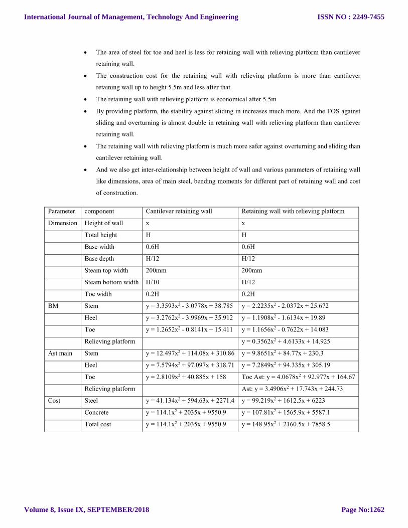
The area of steel for toe and heel is less for retaining wall with relieving platform than cantilever
retaining wall.
The construction cost for the retaining wall with relieving platform is more than cantilever
retaining wall up to height 5.5m and less after that.
The retaining wall with relieving platform is economical after 5.5m
By providing platform, the stability against sliding in increases much more. And the FOS against
sliding and overturning is almost double in retaining wall with relieving platform than cantilever
retaining wall.
The retaining wall with relieving platform is much more safer against overturning and sliding than
cantilever retaining wall.
And we also get inter-relationship between height of wall and various parameters of retaining wall
like dimensions, area of main steel, bending moments for different part of retaining wall and cost
of construction.
Parameter component Cantilever retaining wall Retaining wall with relieving platform
Dimension Height of wall x x
Total height H H
Base width 0.6H 0.6H
Base depth H/12 H/12
Steam top width 200mm 200mm
Steam bottom width H/10 H/12
Toe width 0.2H 0.2H
BM Stem y = 3.3593x2 - 3.0778x + 38.785 y = 2.2235x2 - 2.0372x + 25.672
Heel y = 3.2762x2 - 3.9969x + 35.912 y = 1.1908x2 - 1.6134x + 19.89
Toe y = 1.2652x2 - 0.8141x + 15.411 y = 1.1656x2 - 0.7622x + 14.083
Relieving platform y = 0.3562x2 + 4.6133x + 14.925
Ast main Stem y = 12.497x2 + 114.08x + 310.86 y = 9.8651x2 + 84.77x + 230.3
Heel y = 7.5794x2 + 97.097x + 318.71 y = 7.2849x2 + 94.335x + 305.19
Toe y = 2.8109x2 + 40.885x + 158 Toe Ast: y = 4.0678x2 + 92.977x + 164.67
Relieving platform Ast: y = 3.4906x2 + 17.743x + 244.73
Cost Steel y = 41.134x2 + 594.63x + 2271.4 y = 99.219x2 + 1612.5x + 6223
Concrete y = 114.1x2 + 2035x + 9550.9 y = 107.81x2 + 1565.9x + 5587.1
Total cost y = 114.1x2 + 2035x + 9550.9 y = 148.95x2 + 2160.5x + 7858.5
International Journal of Management, Technology And Engineering
Volume 8, Issue IX, SEPTEMBER/2018
ISSN NO : 2249-7455
Page No:1262

REFERENCES
1. Shravya Donkada and Devdas Menon, “Optimal design of reinforced concrete retaining walls”, The
Indian concrete journal. April 2012, page 9-18
2. S. S.Patil and A. A. R. Babgan, “analysis and design of reinforced concrete stepped cantilever
retaining wall”, IJRET, vol. 04, Feb-2015, page 46-67
3. Rupa B. Patil, G. R. Patil, “Design and detailing of counter fort retaining walls for construction site”,
International journal of informative & fururistic research, Vol. 3, September 2015, page 61-71
4. Tamadher abood, Haten E. Younis Eldawi, Faeza R. Elnaji Abdulrahim, “Design of Cantilever
retaining wall with 4m height ”, Imternational journal of civil and structural engineering research, vol.
3, April 2015, pp 318-326
5. Inder kummar Lilani, Dr. Rakesh Patel, “Analysis of counterfort retaining wall in non over flow
section of gravity dam” , IJSRD, Vol. 5, May 2017, pp. 920-924
6. Sarita Singla and Er. Sakshi Gupta, “Optimisation of reinforced concrete walls of varing heights using
relieving platform”, IJERT, Vol. 4, June 2015, pp 1071-1077
7. Yash Chaliawala, Gunvant Solanki, Anuj K. Chandiwala, “Comparative study of cantilever and
counter fort retaining wall”, International journal of advanced engineering and research development,
Vol. 2, Dec. 2015, pp. 221-224
8. S. Tatahari, R. Sheikoleslami, M. Shadfaran and M. Pourbaba, “Optimum Design of gravity retaining
walls using charged system search algorithm”, Hindawi Publishing corporation, sep. 2012,
9. Su Yang, Amin Chegnizadeh and Hamid Nikraz, “Review of studies on retaining walls behavior on
dynamic/ seismic condition”, vol. 3, Nov 2013, pp. 1012-1021
10. Swati Nagare, Rutuja Shinde, Sushma Ladkat and Komal Mahisare, “Case study of retaining wall”,
April 2017
11. IS 14458 (1998): Guidelines for retaining wall for hill area, part-1: selection of type of wall
12. IS 14458 (1998): Guidelines for retaining wall for hill area, part-2: Design of retaining/ breast walls
13. IS 14458 (1998): Guidelines for retaining wall for hill area, part-3: Construction of Dry stone walls
International Journal of Management, Technology And Engineering
Volume 8, Issue IX, SEPTEMBER/2018
ISSN NO : 2249-7455
Page No:1263