Embed Size (px)
Citation preview

Design And Analysis Of Heat Resistant Ferrule Used In Heat Exchanger
Tube By Using CFD
Vibhavari. Y. Chaudhari,
D.Y.Patil college of
engineering, Akurdi, pune-
44
Prof. P. T. Nitnaware,
D.Y.Patil college of
engineering, Akurdi, pune-
44
Prof. A. S. Dhekane
D.Y.Patil college of
engineering, Akurdi, pune-
44
Abstract
Many modern Generator or Exchanger operates in
high-temperature environments. These exchangers
are associated with the chiller system where the
where the tube-sheet–tube-ferrule assemblies are
exposed to gasses at temperatures approaching
1200⁰C. because sulfur compounds are present in the
process gas, the carbon steel tube sheet and tubes in
the assembly will be deteriorated by sulfidation as the
operating metal temperature rises above
800°C.Ferrule systems are used to protect the carbon
steel from exposure to excessive temperatures. The
temperature distribution in the steel tube-sheet–tube-
ferrule system is affected by process gas flow and
heat transfer through the assembly. A computational
fluid dynamics investigation was conducted to study
the flame flow and Temperature distribution on tube
inlet and ferrule. It was found that the configuration
of the ferrule installation has a large influence on the
temperature distribution in the steel materials and,
therefore, the possible sulfidation of the carbon steel
parts.
Keywords: CFD, non-premixed combustion, ferrule,
Standard kepsilon turbulence model, diesel fuel,
1. Introduction
The waste heat exchanger studied is a typical
ASME Boiler and Pressure Vessel Code Section VIII
Division 1design with a flexible tube sheet. The
carbon steel tube sheet is protected by a two-piece
solid-head ferrule system. For modern heat
exchangers, the tube-sheet design temperature is
typically in the range of 650–700°F for ASME Code
1 tube-sheet calculations. The carbon steel
component materials are SA 516-70 plate for the tube
sheet and SA 106B for the tubes. The ferrules are
content ceramic material. The ferrule heads are
arranged such that the cold assembly gap closes at
operating temperatures due to thermal expansion.
Ferrules are used in direct fired/exhaust fired
VAM (vapor absorption machine) tube to tube sheet
joints weld protection from direct flame Also used to
provide protection to the inlet ends of shell and tube
heat exchangers in application where high
temperature or corrosive material are processed. as
shown in fig:2
Ferrules denote either specialized strengthening
rings and caps placed on components, or fittings used
in heat exchangers, boiler tubes and condenser tubes
as shown in fig: 1.A double-ring ceramic ferrule
member insertable into a fire tube of a sulfur plant
boiler or cooler, the an article of manufacture capable
of reducing damage caused by high temperature gas
flow through a fire tube, thereby to protect the fire
2055
International Journal of Engineering Research & Technology (IJERT)
Vol. 2 Issue 5, May - 2013
ISSN: 2278-0181
www.ijert.org
IJERT
IJERT

tube and the tube sheet through which the fire tube
extends. The present ferrule member provides
improved anchoring capability and increased
resistance to fire tube erosion .the sulfur boilers or
coolers are typically comprised of a structure
containing water which absorbed heat from the hot
gas flow directed through the fire tubes disposed in
water, heat being thereby exchanged. The water is
contained within the structure having a wall which is
commonly referred to as a tube sheet, the fire tube
extending through the tube sheet. According to this,
ceramic ferrule with collar is inserted into each fire
tube, approximately half the length of ceramic ferrule
being within said fire tube. Hot gas flow is thus
directed through the ceramic ferrule extending sufficiently into the fire tube such that the hot gas
flow does not directly contact the fire tube along the
portion of the fire tube which contacts the tube sheet. The investigation limited to the tube filled area
of the tube sheet assembly. The exchanger has a
triangular pitch pattern dictating annular head
geometry for the ferrules.
Knowing the temperature profile of the system is
critical to the mechanical design of the tube sheet and
the prevention of sulfidation of the steel components,
as discussed by Martens et al. The thermal profile of
a tube-sheet protection system using a ferrule and
castable refractory system on the face of the tube
sheet is investigated in.
The tubes are welded in the end to the wall of
the boiler. Virtually all cracks occur at welded joints
or at openings. This is a frequent, costly and
dangerous occurrence. The root cause is corrosion
fatigue and the fatigue cycling is thermally driven.
The thermal fluctuation that occurs is due to the slag
and the change of operating conditions also creates
alternating stresses. As a result the boiler tubes,
welding of tube to tube sheet joint, ceramic ferrule
are subjected crack.
The Ferrule used for this investigation having
50mm length, collar thickness =4mm, Diameter of
collar= 32mm, OD of ferrule =20.5mm, ID of ferrule
=16.6 mm as shown in fig:1 and Material of ferrule
material consists of silica60%, magnesia 26%,
alumina 12%, calcia/ferric oxide 2%.Therefore
because of low alumina the strength of the ferrule
will be less. And the chances of collar damaged of
ferrule will increased. Because of the hot gas
temperature will direct contact with the ferrule. Also
from this tube or tube to tube sheet weld joint failure
also occur. Using this material, Dimensional
accuracy of ferrule is not acceptable: length, ovally
etc. Due to dimensional variation fitment in Tube ID
is not accurate: falling during transit etc. may lead to
joint failure.
In this investigation, the failed tube specimen of
HTG( high temperature generator)and failed ceramic
ferrule specimen were collected from the direct fired
vapor absorption machine and dimensional accuracy
of the ceramic ferrule corrected using the change of
material and compare existing and new ferrule using
experimently.CFD study was conducted to establish
the temperature profiles at tube inlet and ferrule
The flame temperature, gas properties and material
properties used were specific for the unit under study.
2. Methodology
Computational fluid dynamics is part of fluid
mechanics that uses numerical method and algorithm
to solve and analyse problem that related to fluid
flow. CFD – FLUENT 6 is used for the modelling
and simulation in this project. CFD – FLUENT 6 is
computer software that allows modelling and
simulation of flow of fluid and heat and mass transfer
in complex geometries. It is capable to complete
meshing flexibility, solving flow problems with
unstructured meshes that can be generated through
the complex geometries
2.1 Geometry Design/Meshing Geometry
ICEM:
ICEM which is a geometric modelling and grid
generation tool is provided along with the FLUENT
technology. ICEM allows the user to import
geometry from other designing software or computer-
aided design (CAD) software or create own geometry
entirely based on ICEM itself. Figure 3 shows a
2056
International Journal of Engineering Research & Technology (IJERT)
Vol. 2 Issue 5, May - 2013
ISSN: 2278-0181
www.ijert.org
IJERT
IJERT

sketch of the computational domain used in this
study. The temperature of the fuel and ambient air
was considered to be 37˚C. And the ambient pressure
was 101325 Pa.
2.2 Geometry and mesh generation:
Mesh generation was performed in a Fluent pre-
processing program called ICEM. The current model
is cavity-based fuel injector with non-premixed
combustion as shown in figure 4. The geometry of
the 2D combustor was created in ICEM meshing
software only where 19050 nodes, 18582
quadrilateral cells, 36698 2D interior faces, 48 2D
velocity-inlet faces,42 2D pressure-outlet faces, 842
2D wall faces, mesh was created. The mesh was then
refined at boundaries of the combustor a two million
cell hex-dominant of high temperature and velocity
gradients to give a grid independent 3.6 million cell
mesh. In this particular model the walls of the
combustor duct do not have thicknesses. The domain
is completely contained by the combustor itself;
therefore there is actually no heat transfer through the
walls of the combustor.
2.3 Fuel Model:
When fuel is injected into the combustion chamber as
a spray, heat transfer, phase change, chemical
transformation and occur. These processes convert
fuel liquid into volatile vapor and gases, which later
on burn in the oxidizing environment surrounding the
spray. In CFD modeling these processes are critical
because they control the overall performance of the
combustion process. As the liquid droplet enters the
hot combustion chamber, heat transfer between the
droplet and the hot surroundings occurs, and
vaporization starts. CFD Analysis was carried out
using FLUENT for the combustion analysis of diesel
fuel. Diesel was injected with a nozzle of 0.001 dia.
At a pressure of bar, air was inducted at atmospheric
temperature & pressure and diesel fuel was injected
through the injector at a pressure of 20bar directly
into the combustion chamber.
2.4 Boundary condition:
The boundary conditions are such that, the air
inlet and fuel inlet surfaces are defined as mass flow
inlets and pressure outlet. In this particular model the
walls of the combustor duct do not have thicknesses.
The domain is completely contained by the
combustor itself; therefore there is actually no heat
transfer through the walls of the combustor. During
analysis we have taken same pressure for both fuel
and air for all the models. Temp inlet and temp outlet
conditions were taken on the left and right boundaries
respectively. Pressure inlet condition was taken for
fuel injector. The walls, obstacles and other materials
were set to standard wall conditions. The
computations were initially carried out with
various levels of refinement of mesh.
Temperature of fuel injection 40°C
Fuel consumption is 135kg/hr
Flow rate of air is 1 kg/s
Temperature of air injection: 40°C
Atmospheric pressure: 101325 Pa
Flame temperature: 1200ºC
2.5 Modeling Details:
In the CFD model, the Standard k-𝜺turbulent model
is selected which is one of the most common
turbulence models. It is a two equation model that
means it includes two extra transport equations to
represent the turbulent properties of the flow. This
two equation model accounts for history effects like
convection and diffusion of turbulent energy. Non-
Premixed Combustion enables the calculation of
turbulent reacting flow using the non-premixed
combustion model. This option is available only for
2057
International Journal of Engineering Research & Technology (IJERT)
Vol. 2 Issue 5, May - 2013
ISSN: 2278-0181
www.ijert.org
IJERT
IJERT

turbulent flows using the pressure-based solver. Non-
premixed modeling involves the solution of transport
equations for one or two conserved scalars (the
mixture fractions). Equations for individual species
are not solved. Instead, species concentrations are
derived from the predicted mixture fraction fields.
The thermo chemistry calculations are pre-processed
and then tabulated for look-up in ANSYS FLUENT.
Interaction of turbulence and chemistry is accounted
for with an assumed-shape Probability Density
Function (PDF).Energy equations were considered
and the solution was initialized from the air inlet for
simplicity. Discrete phase model were considered to
calculating the particle trajectories for each discrete
phase injection. The convergence criterion
requirement is set to be 10-3 for energy and about 10-
3 for the other terms of the transport equations.
2.6 CFD Result:
The reactive simulations presented in this section are
carried in the geometry (Figure-3)
In this section results of flame flow and temperature
at tube inlet observed .The red colour regions are the
regions where the properties attain their maximum
values. The blue coloured regions indicate the
regions where the properties are at their minimum.
The properties that were analyzed were static
temperature,
2.6.1 Static Temperature:
From Fig 5 it is evident that static temperature
increases from inlet to the outlet. This is due to
combustion of the air and injected diesel fuel. The
heat released due to combustion heats up the
combustion products (water) and hence, an increase
in the static temperature from 423 to 1392 K is
observed. Temperature at inlet of tube 1296K and
flame temperature 1392K at inlet is observed.
2.6.2 Static temperature with low alumina ferrule
wall and at tube inlet (outlet):
:
From Fig 6 it is evident that static temperature
increases from inlet to the outlet using CFD result.
This is due to combustion of the air and injected
diesel fuel it was found that the temperature on
ferrule becomes high. Average temperature on ferrule
wall is 1290.76K and average temperature at outlet is
1276.24 K is observed.
2.6.3 Static temperature with high alumina ferrule
wall and at tube inlet (outlet):
From Fig 7 it is evident that static temperature
increases from inlet to the outlet using CFD result.
This is due to combustion of the air and injected
diesel fuel it was found that the temperature on
ferrule becomes high. Average temperature on ferrule
wall is 1470K and average temperature at outlet is
1296.24 K is observed.
2058
International Journal of Engineering Research & Technology (IJERT)
Vol. 2 Issue 5, May - 2013
ISSN: 2278-0181
www.ijert.org
IJERT
IJERT
2.7 Experimental methodology
2.7.1 Materials and Specimens: The experiments were performed using a carbon steel
tube and ceramic ferrule, as shown in Fig. The
dimensions of the tube and ferrule are listed in Table
1 and the chemical and mechanical properties shown
in table 2
Tube Ceramic
ferrule
Outer diameter 25.4 20.5+0.4/-0.8
Thickness 2.05 2
Inner diameter 16.6+0.5
Length 50+/-3.0
Collar thickness 4+/-1.0
Collar OD 32+/-1.0
Existing ferrule
(molded)
New ferrule
(machined)
Material ceramic ceramic
Composition Alumina12% Alumina 94%
Silica60% Silica 1%`
calcia/ferric
oxide 2%
calcia 1%
Magnesia26%, Magnesia1%
Tensile
strength, kpsi
15 25
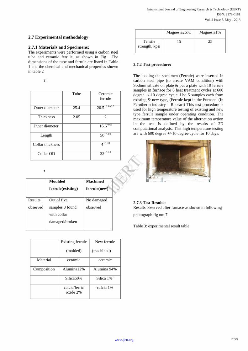
2.7.2 Test procedure:
The loading the specimen (Ferrule) were inserted in
carbon steel pipe (to create VAM condition) with
Sodium silicate on plate & put a plate with 10 ferrule
samples in furnace for 6 heat treatment cycles at 600
degree +/-10 degree cycle. Use 5 samples each from
existing & new type, (Ferrule kept in the Furnace. (In
Ferotherm industry – Bhosari) This test procedure is
used for high temperature testing of existing and new
type ferrule sample under operating condition. The
maximum temperature value of the alternation action
in the test is defined by the results of 2D
computational analysis. This high temperature testing
are with 600 degree +/-10 degree cycle for 10 days.
2.7.3 Test Results:
Results observed after furnace as shown in following
photograph fig no: 7
Table 3: experimental result table
Moulded
ferrule(existing)
Machined
ferrule(new)
Results
observed
Out of five
samples 3 found
with collar
damaged/broken
No damaged
observed
2059
International Journal of Engineering Research & Technology (IJERT)
Vol. 2 Issue 5, May - 2013
ISSN: 2278-0181
www.ijert.org
IJERT
IJERT

3. Results and discussion:
Detailed temperature profiles for the system were
developed. For comparison reasons, the temperatures
indicated by CFD analyses were queried at the same
locations used for the experimental study .the CFD
study indicates temperature of 1296K at the tip of the
tube. This temperature is well above the 600°F
maximum design temperature typically used for
carbon steel components to assure acceptable service
life. The rate of sulfidation that would be expected to
occur at 835°F would not be considered an
acceptable service life.
From this paper it is concluded that temperature
difference is due to the effects of heat transfer by
radiation were addressed in the CFD analysis. Inspection of and CFD analysis results makes it
apparent that the temperature at the tip of the tube–
to–tube-sheet junction, noted as in Fig 5 and Fig 6, is
highly dependent on the amount of process gas.
It is also apparent that the tube to tube sheet weld
joint during operation and condition of high alumina
ceramic ferrule in this joint and throughout the
system are very important to controlling the process
gas bypassing and for the successful protection of the
carbon steel components.
The temperature profile in the tube end, as
indicated in the analysis, has a considerable gradient.
The gradient results in the highest temperature
occurring at the tip of the tube at the area of the tube–
to–tube-sheet attachment weld. This is the area that is
usually observed to have sulfidation corrosion when
the tubesheet–tube protection system is not adequate.
From a practical engineering viewpoint, the possible
elevated temperature at the tip of the tube–to–tube-
sheet joint is a greater concern for sulfidation
corrosion failure than for exceeding the tube-sheet
design temperature.
4. Conclusion:
The use of CFD provides the design engineer
considerable in-sight into the critical temperature
profile at the tip of the tube–to–tube-sheet junction.
The CFD analysis provides qualification and
quantification of this critical temperature profile and
assures the design engineer that a suitable design
temperature is utilized for ASME Code calculations.
The development of ferrule for weld protection from
direct flame can be achieved to assess change the
material composition and manufacturing method.
The mode of failure for a boiler, heat exchanger
tube end crack was investigated and suggested
solution for a ceramic ferrule. The ferrule is to be
fitted on to the inlet end of the tube to prevent
thermal shock when hot flue gas enters the tube.
Ceramic materials are chemically inert to almost all
materials. The paper shows that all ferrule systems used to
protect the carbon steel tube sheets and tubes of heat
exchangers are critical Therefore, the used of high
alumina machined ferrule in place of moulded ferrule
will get the Get better quality and accurate
dimensioned ferrule. Also Fitment problem shall get
eliminated.
.
5. References: [1] J. P. Kalita , K .M. Pandey & A .P .Singh
“Computational Analysis of Combustion
Chamber Using Cavity-based fuel Injector with
Non-Premixed Combustion Model” Global
Journal of Researches in Engineering Mechanical
and Mechanics Engineering, Global Journals Inc.
(USA) , June 2012, Volume 12 Issue 3 Version
1.0.ISSN: 2249-4596
[2] Abbas Khoshhal, Masoud Rahimi, Sayed Reza
Shabanian, and Ammar Abdulaziz Alsairafi
“CFD modeling of reduction in NOx emission
using HiTAC technique” World Academy of
Science, Engineering and Technology 38 ,2010
[3] Mike Porter , Dennis Martens , Sean McGuffie , John Wheeler “A means of avoiding sulfur
recovery reaction furnace fired tube boiler
failures”, ASME Pressure Vessels & Piping
Conference , July 27 - 31, 2009
[4] Shahida Begum, A.N Mustafizul Karim ,
Mohamed Ansari M. Nainar and Sukhana
Sevah1 “Analysis of End Crack in Boiler Tube”
Advanced Materials Research, Trans Tech
2060
International Journal of Engineering Research & Technology (IJERT)
Vol. 2 Issue 5, May - 2013
ISSN: 2278-0181
www.ijert.org
IJERT
IJERT
Publications, Switzerland, 2012, pp 749-752,
Vol. 576
[5] James E. Macphee, Mathieu Sellier, Mark Jermy
and Edilberto Tadulan “CFD modeling of
pulverized coal combustion in a rotary lime kiln”
Seventh International Conference on CFD in the
Minerals and Process Industries, CSIRO,
Melbourne, Australia December 2009, 9-11
[6] Kazui Fukumoto and Yoshifumi Ogami,
”Simulation of CO-H2-Air Turbulent
Nonpremixed Flame Using the Eddy Dissipation
ConceptModel with Lookup Table Approach”, Journal of Combustion, Hindawi Publishing
Corporation, 2012, 11 pages.
[7] Michael A. Porter, Dennis H. Martens, Thomas
Duffy, Sean McGuffie “High-Temperature Heat
Exchanger Tube-Sheet Assembly Investigation
With Computational Fluid Dynamics” Journal of
Pressure Vessel Technology, ASME, May 2007, 313, Vol. 129
[8] Subramani A. , Ambedkar B , Sarat Chandra
Babu, “Numerical simulation of diluent effect on
no emission in a turbulent premixed methane
flames”, International Journal on Applied
Bioengineering, July 2008, Vol.2
[9] Martens, D. H., et al., 1996, “Analysis of
Tubesheet Stresses in a Sulfur Re-covery Unit,”
Structural Integrity, NDE, Risk and Material
Performance for a Petroleum, Process and Power,
Prager, ed., ASME, New York,pp. 361–371,PVP-
Vol. 336
[10] Terry Wall, Yinghui Liua, Chris Spero “An
overview on oxyfuel coal combustion” State of
the art research and technology development
chemical engineering research and design,
ScienceDirect 2009 ,1003–1016
[11] W. Malalasekera, S.S. Ibrahim, A.R. Masri, S. K.
Sadasivuni “Large eddy simulation of premixed
and non-premixed Combustion” Proceedings of
the 37th National & 4th International Conference
on Fluid Mechanics and Fluid Power, IIT
Madras, Chennai, India, December 2010, 16-18,
[12] A. Mannino1, G. Calchetti, M. Rufoloni , R.
Marretta “Study of Hydrogen–Air Non–premixed
Combustion”. University of Palermo (Italy).
ENEA Casaccia Research Centre, Rome (Italy)
[13] Zhuyin Ren a, Graham M. Goldin , Varun
Hiremath , Stephen B. Pope “Simulations of a
turbulent non-premixed flame using combined
dimension reduction and tabulation for
combustion chemistry” Fuel 105, Science Direct ,
2013, 636–644,
2061
International Journal of Engineering Research & Technology (IJERT)
Vol. 2 Issue 5, May - 2013
ISSN: 2278-0181
www.ijert.org
IJERT
IJERT