Embed Size (px)
Citation preview
Mechanics and Mechanical Engineering
Vol. 22, No. 1 (2018) 59–64
c⃝ Lodz University of Technology
Design and Analysis of Ejection in Sub Wheel Assembly
S. RajendranS. M. Abish
M. SakthivelP. Sandeep
S. Rahul Krishna
Department of Mechanical EngineeringJaya Engineering College
Anna University, Chennai 600025, Tamilnadu, [email protected]
Received (13 August 2017)
Revised (19 August 2017)
Accepted (15 September 2017)
Traveling in remote areas at nights is very risky and tire getting puncture at that timeis dangerous. To avoid any of this complications a sub wheel system is installed inthe vehicle. Sub wheels helps to go to required destination and change the puncturewheel. The tires used in this system are mold tires so they don’t get affected by the roadconditions. The sub wheel is operated by means of a hydraulic system. Power for thissub wheel is provided from the engine placed in the back of the vehicle. This is systemis very useful heavy weight vehicle which travel in difficult terrain (army vehicles).Theheight of the car is increased so that Sub wheels won’t affect the chassis or the engine.This type of system is used in le24race but they only use hydraulic system to lift thecar. The advantage of this system is its user friendly and effective to use. By pressing abutton required sub wheel comes down and start to function. By using CATIA a diagramof this system is drawn to check it’s various forces acting on it.
Keywords: four wheeler car, sub-wheel assembly, force analysis, design of wheel.
1. Introduction
In this 21st century new products are invented every minute. There great leap inautomobile industry in every aspect. But the materials used in tires for automobilecan get damage. This is becoming one of the security reasons while travelling atnight and remote areas. For this purpose our project “Design and Analysis ofEjection in Sub Wheel Assembly”. This will be very useful for female while drivingalone. by pressing a button sub wheel assembly gets down and works by the powerof the engine.
https://doi.org/10.2478/mme-2018-0006
60 Rajendran, S., Abish, S. M., Sakthivel, M., Sandeep, P. and Rahul Krishna, S.
1.1. Mould tires
Mould tires are tires that are not supported by air pressure. The tires are made ofElastomer. The size of front wheel is smaller than rear wheel. Rear wheel is largerbecause the entire load will be acting on the rear of the vehicle. The load is dueto Gearless engine placed in the back of the car. These tires are used because theroad conditions don’t affect them. Front wheel diameter - 4.5 inches. Front wheelthickness - 2 inches. Rear wheel diameter - 6.5 inches. Rear wheel thickness - 2inches.
1.2. Gearless engine
Engine used for operating of rear sub wheel is Air cooled, 4 - stroke, SI engine. Theengine uses automatic transmission. Displacement - 125 CC. Maximum power - 8.6BHP. Maximum torque - 10.12 MN. Stroke - 57.9 mm. Bore - 52.41 mm.
1.3. Mild steel rod
Mild steel (steel containing a small percentage of carbon, strong and tough butnot readily tempered), also known as plain-carbon steel, is now the most commonform of steel because its price is relatively low while it provides material propertiesthat are acceptable for many applications. Low-carbon steel contains approximately0.05–0.25% carbon. Making it malleable and ductile. Mild steel has a relatively lowtensile strength, but it is cheap and easy to form; surface hardness can be increasedthrough carburizing. Mild steel diameter - 25 mm, Front rod length - 11 inches,Rear rod length - 28 inches.
1.4. Shock absorber
A shock absorber it is a hydraulic device designed to absorb and damp shock im-pulses. It does this by converting the kinetic energy of the shock into another formof energy (typically heat) which is then dissipated. Most shock absorbers are a formof dashpot. Shock Absorber Height - 16 inches. Spring Coil Height - 10.5 inches.Spring Coil thickness - 0.4 inch. Number of coils in each spring - 15.
1.5. Gear sprocket
A Gear sprocket made of mild steel is welded to rear wheel arrangement. Chainis used a connection between the engine and the wheel assembly to transmissionof power. Sprocket is water resistant and can handle any shocks produced whiletraveling. Sprocket Diameter - 2.4 inches.
2. Construction of sub wheel assembly
2.1. Rear wheel
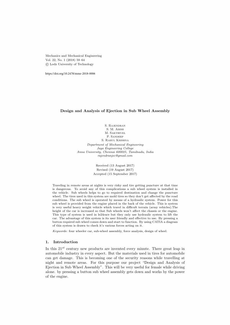
Figure 1 shows on mould tires are fixed to mild Steel rod. Disc brakes are fixedon either sides of the rear wheel assembly. A Gear sprocket is welded on the rearwheel assembly. An Electric motor is placed in the rear side of the car. This electricmotor is used to control the position of the Rear wheel assembly. Suspension rodsare placed to withstand to load of the vehicle.
Design and Analysis of Ejection in Sub Wheel Assembly 61
Figure 1 Sub wheel assembly
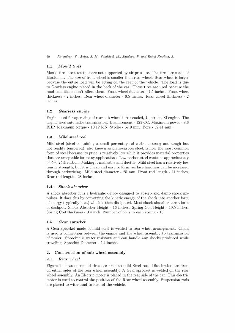
Figure 2 Model of sub wheel assembly
62 Rajendran, S., Abish, S. M., Sakthivel, M., Sandeep, P. and Rahul Krishna, S.
A Gearless Two wheeler engine is placed in the rare of the car. A steel frame iswelded to the rear to support the engine. A chain is connected between engine andsprocket. A leaf support is placed between wheels and engine.
2.2. Front wheel
Front sub wheel assembly is fixed to the frame. The steering control is given to thefront wheel. The mounded tires are fixed to the steel rod. The steel rod is fixed tothe stub. And the other end of the stub is connected to the steering rod.
3. Working principle
Gearless engine is placed in the back of the car. A steel frame is welded at therear to support the engine. The engine is used for motion of the rear sub wheel.The height of the car is increased so that sub wheels don’t touch the engine or thedriving shaft. The sizes of the front tires are smaller than the rear tires. The frontsub wheel is moved by the power in the rear wheel. Steering control is alone givento the front wheel. An electric motor is fixed so that it is helpful for the ejectionof sub wheels. Wheels used in this are moulded. Mould tires are used becausethey won’t get punctured. The shock absorbers are provided to withstand the roadconditions as shown in the Figure 2.
The design of sub wheel assembly is made by using CATIA V5 software, wherethe parts such as the wheel, mild steel rod, sprocket, disc, bolts, nuts, suspensionrod, and spring are drawn separately. Then all the parts are assembled in a singleplane by fixing the mild steel rod. Taking the required parts on the screen andfixing the faces of the parts that are to be fixed. This assembly design is madeto analyse the system to withstand the required load. This assembly then can beexported to ansys software to analyse.
4. Calculation
• Weight of the material W = 200 Kg = 1962 N,
• Distance between two consecutive coils = 15.5 mm,
• Total number of coils, n = 15.
• Mean coil diameter, D = 55 mm,
• Diameter of wire, d = 7 mm,
• Modulus of rigidity, C = 70.3× 10³ N/mm2.
• Deflection = Distance between two consecutive coils × Number of coils:
d = 15.5× 15 = 232.5 mm.
• Deflection = 8WD3nCd4
d4 = 8×1962×553×15232.5×70.3×103 = 3.917×10¹⁰
16344750 = 2396.488169
d = 6.996 ≈ 7 mm
Design and Analysis of Ejection in Sub Wheel Assembly 63
5. Results and analysis
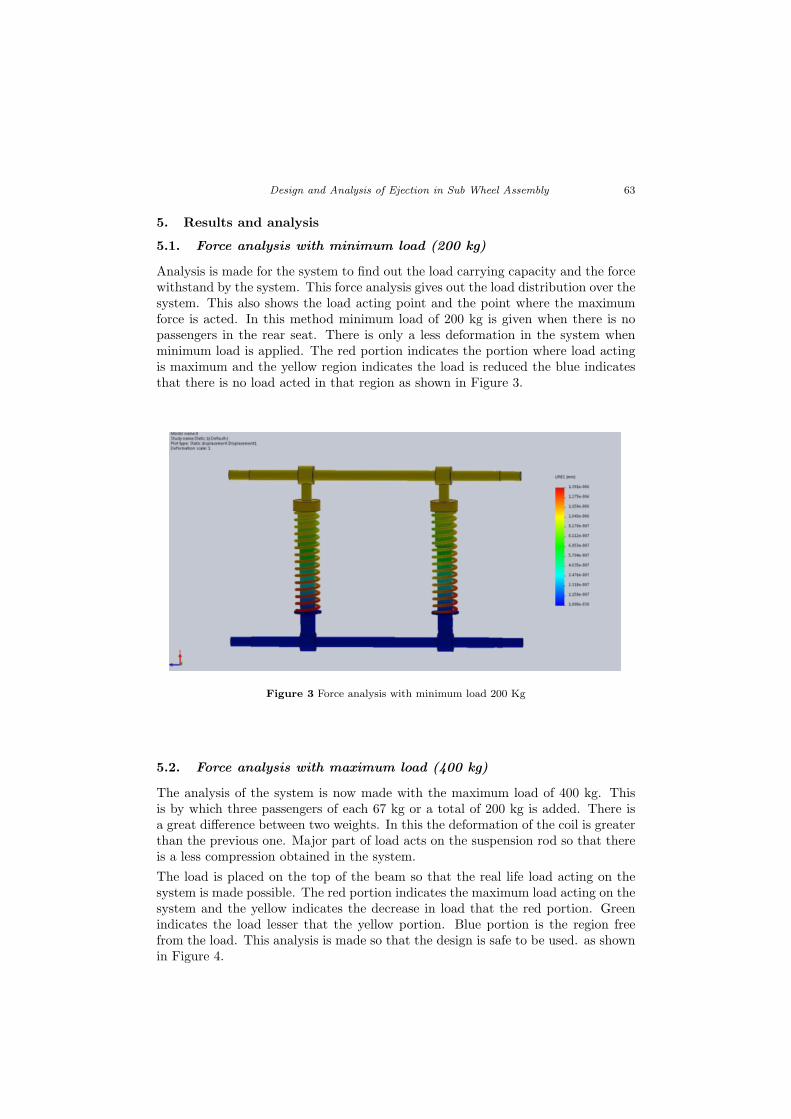
5.1. Force analysis with minimum load (200 kg)
Analysis is made for the system to find out the load carrying capacity and the forcewithstand by the system. This force analysis gives out the load distribution over thesystem. This also shows the load acting point and the point where the maximumforce is acted. In this method minimum load of 200 kg is given when there is nopassengers in the rear seat. There is only a less deformation in the system whenminimum load is applied. The red portion indicates the portion where load actingis maximum and the yellow region indicates the load is reduced the blue indicatesthat there is no load acted in that region as shown in Figure 3.
Figure 3 Force analysis with minimum load 200 Kg
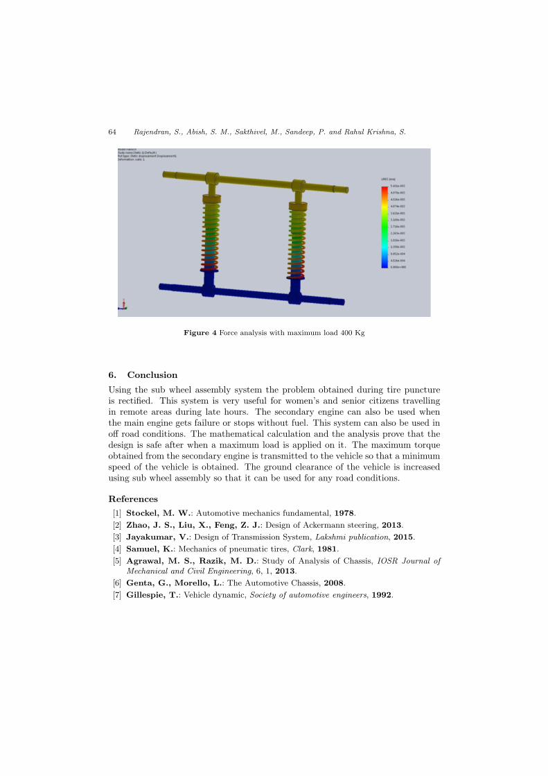
5.2. Force analysis with maximum load (400 kg)
The analysis of the system is now made with the maximum load of 400 kg. Thisis by which three passengers of each 67 kg or a total of 200 kg is added. There isa great difference between two weights. In this the deformation of the coil is greaterthan the previous one. Major part of load acts on the suspension rod so that thereis a less compression obtained in the system.
The load is placed on the top of the beam so that the real life load acting on thesystem is made possible. The red portion indicates the maximum load acting on thesystem and the yellow indicates the decrease in load that the red portion. Greenindicates the load lesser that the yellow portion. Blue portion is the region freefrom the load. This analysis is made so that the design is safe to be used. as shownin Figure 4.
64 Rajendran, S., Abish, S. M., Sakthivel, M., Sandeep, P. and Rahul Krishna, S.
Figure 4 Force analysis with maximum load 400 Kg
6. Conclusion
Using the sub wheel assembly system the problem obtained during tire punctureis rectified. This system is very useful for women’s and senior citizens travellingin remote areas during late hours. The secondary engine can also be used whenthe main engine gets failure or stops without fuel. This system can also be used inoff road conditions. The mathematical calculation and the analysis prove that thedesign is safe after when a maximum load is applied on it. The maximum torqueobtained from the secondary engine is transmitted to the vehicle so that a minimumspeed of the vehicle is obtained. The ground clearance of the vehicle is increasedusing sub wheel assembly so that it can be used for any road conditions.
References
[1] Stockel, M. W.: Automotive mechanics fundamental, 1978.
[2] Zhao, J. S., Liu, X., Feng, Z. J.: Design of Ackermann steering, 2013.
[3] Jayakumar, V.: Design of Transmission System, Lakshmi publication, 2015.
[4] Samuel, K.: Mechanics of pneumatic tires, Clark, 1981.
[5] Agrawal, M. S., Razik, M. D.: Study of Analysis of Chassis, IOSR Journal ofMechanical and Civil Engineering, 6, 1, 2013.
[6] Genta, G., Morello, L.: The Automotive Chassis, 2008.
[7] Gillespie, T.: Vehicle dynamic, Society of automotive engineers, 1992.