Embed Size (px)
Citation preview

Design and analysis of an alignmentprocedure using computer-generatedholograms
Laura E. CoyleMatthew B. DubinJames H. Burge
Downloaded From: https://www.spiedigitallibrary.org/journals/Optical-Engineering on 11 Feb 2022Terms of Use: https://www.spiedigitallibrary.org/terms-of-use

Design and analysis of an alignment procedure usingcomputer-generated holograms
Laura E. CoyleMatthew B. DubinJames H. BurgeUniversity of ArizonaCollege of Optical Sciences1630 East University BoulevardTucson, Arizona 85721E-mail: [email protected]
Abstract. A procedure that uses computer-generated holograms (CGHs)to align an optical system’s meters in length with low uncertainty and real-time feedback is presented. The CGHs create simultaneous three-dimen-sional optical references, which are decoupled from the surfaces of theoptics allowing efficient and accurate alignment even for systems thatare not well corrected. The CGHs are Fresnel zone plates, where thezero-order reflection sets tilt and the first-diffracted order sets centration.The flexibility of the CGH design can be used to accommodate a widevariety of optical systems and to maximize the sensitivity to misalign-ments. An error analysis is performed to identify the main sources ofuncertainty in the alignment of the CGHs and to calculate the magnitudesin terms of general parameters, so that the total uncertainty for any specificsystem may be estimated. A system consisting of two CGHs spaced 1 mapart is aligned multiple times and re-measured with an independent testto quantify the alignment uncertainty of the procedure. The calculated andmeasured alignment uncertainties are consistent with less than 3 μrad oftilt uncertainty and 1.5 μm of centration uncertainty (1σ). © 2013 Society ofPhoto-Optical Instrumentation Engineers (SPIE) [DOI: 10.1117/1.OE.52.8.084104]
Subject terms: optical alignment; alignment datum; computer-generated holograms;Fresnel zone plates.
Paper 130696P received May 10, 2013; revised manuscript received Jul. 23, 2013;accepted for publication Jul. 24, 2013; published online Aug. 28, 2013.
1 IntroductionAs the technologies for manufacture and metrology advance,optical systems are being designed with more complexitythan ever before. Given these prescriptions, alignment canbe a limiting factor in determining their final performance.Systems for astronomical telescopes, lithography, and high-energy lasers may require the alignment of multiple compo-nents with micron-level accuracy over many meters. Thegoal of this work is to develop a low-uncertainty alignmentprocedure that can be applied to a variety of optical systems.
There are many tools, mechanical and optical, availablefor alignment. A coordinate measuring machine (CMM)uses a touch probe to measure the position of features inthree dimensions. With careful operation, a CMM can obtaina repeatability of 3 μm along a single-measurement axis withan additional uncertainty of 3 μm∕m over large volumes.1
However, a CMM is not practical for large assemblies, asthe largest CMMs are only a few meters in length; also,the optics are commonly housed in mechanical structuresthat restrict the probe’s access to datum features. CMMs can-not provide real-time feedback of the system alignment andmake the process lengthy. Laser trackers are also used foroptical alignment.2 They have a typical accuracy of4 μm� 0.8 μm∕m.3 Operation requires a line of sight fromthe tracker to a sphere-mounted retro-reflector target incontact with a datum, which also can be hindered by themechanical mounting structure. Real-time feedback of thesystem alignment can only be obtained with multiple mea-surements, and thus, multiple laser trackers are required,which is often prohibitively expensive. Alignment telescopesand axicons create an optical axis that can be used to center
components. The centration accuracy depends on thestraightness of the axis and the ability to align targets toit.4–6 In a previous experiment, an alignment telescopewith camera eyepiece was rotated on an air bearing to maxi-mize alignment precision, but the centration uncertainty for atarget at a distance of 1 m was 15 μm 1σ.7 For both methods,an additional test is needed to measure the tilt.
This procedure uses computer-generated holograms(CGHs) to create simultaneous three-dimensional opticalreferences and to perform an alignment in multiple degreesof freedom with real-time feedback. The optical referencesare decoupled from the surfaces of the optics allowing accu-rate alignment even for systems that are not well corrected.Transferring the alignment datum to an external reference,this procedure describes the alignment of CGHs, which mustbe separately aligned to the optics. The sensitivity of theinstruments used to track the optical references is a drivingfactor in the final uncertainty; yet good performance can beachieved with off-the-shelf components. This procedure isdesigned to achieve centration uncertainties of a few micronsand tilt uncertainties of a few micro-radians over a distanceof several meters.
In this article, we describe how to use CGHs to align anoptical system and to quantify the residual uncertainty.Section 2 outlines the procedure and describes the advan-tages of using CGHs to create the optical references. Themajor sources of uncertainty are identified in Sec. 3, and theirmagnitudes are calculated in terms of general parameters,so that the total uncertainty for any specific system maybe estimated. Finally, Sec. 4 presents experimental resultsfor the alignment uncertainty a two CGH system and com-pares it with the expected uncertainty from the analysisin Sec. 3.0091-3286/2013/$25.00 © 2013 SPIE
Optical Engineering 084104-1 August 2013/Vol. 52(8)
Optical Engineering 52(8), 084104 (August 2013)
Downloaded From: https://www.spiedigitallibrary.org/journals/Optical-Engineering on 11 Feb 2022Terms of Use: https://www.spiedigitallibrary.org/terms-of-use

2 CGH Alignment ProcedureThe goal of this procedure is to align axi-symmetric asphericoptics in four degrees of freedom, two each in tilt and in cen-tration. Rather than using the optical surfaces, the alignmentdata is transferred to an external reference—a CGH—writtento an optical flat with a reference mark at the pattern’s center.The CGH is rigidly mounted to the optic such that the CGHsurface normal represents the tilt of the optic, and the refer-ence mark represents the optical axis. If the CGH is accu-rately aligned to the optical surface, well-aligned CGHs willproduce a well-aligned system. The ideal alignment caserequires the reference mark at the center of each CGH patternbe coincident with a single axis and the surface normal of theCGH be parallel to that axis.
The alignment procedure uses CGHs that are written withFresnel zone plate (FZP) patterns, so they act like thin lenses.One CGH (CGHA) creates two focused spots, which definethe alignment axis, and then a second CGH (CGHB) isaligned to that axis. The CGHs are aligned in centrationpairwise using a single CGHA, so the alignment axis ismaintained, and multiple CGHBs with different patternsfor a system with three or more optics. The label CGHBis used for optics 2 through n since the alignment procedureand error analysis equations are the same for these CGHs.Any single CGHB is aligned to CGHA with all the othersremoved. An autocollimator is used to align the tilt of eachCGH independently.
2.1 Computer-Generated Holograms
CGHs with varying degrees of complexity have been usedto perform alignment of optical components, often by usingthe optical surfaces.8,9 The CGHs in this procedure aredecoupled from the optics and are designed simply to actlike lenses, though they are preferable to lenses for two mainreasons. First, the CGH patterns are created using a laserwriter for photomasks, and a center reference mark is writtenwith submicron precision. It is difficult to measure the centerof a lens to the same accuracy. Second, multiple patterns canbe combined on a substrate, so a single CGH can act like twolenses with the same axis, but different focal lengths.
Our CGHs use two types of patterns. CGHA consists oftwo concentric FZPs with different focal lengths, and CGHBcontains only one FZP. While the axial spacing of the CGHsis likely constrained by the optical and mechanical designs,the focal lengths of the FZPs are degrees of freedom. Thesefocal lengths can be chosen to increase the sensitivity to cen-tration error.
The CGHs can be phase etched, chrome-on-glass, or acombination. Their design allows flexibility for the intensityin each diffracted order. The desired intensity is in the zeroand first orders specifically, and the wavelength range of the
source must be considered when choosing the etch depth orduty cycle of the CGHs. The non-CGH side of the substrateis anti-reflection coated to avoid unwanted ghosts.
2.2 Alignment of CGHs to Optical Surfaces
This article describes the alignment of CGHs, which mustalso be individually aligned to an optical surface to achievethe desired system performance. For an aspheric mirror, thereis a single optical axis. The CGHs must be aligned to theoptic such that the center of the CGH pattern is coincidentwith the mirror’s optical axis, and its surface normal is par-allel to the mirror’s axis, as in Fig. 1. Since this procedure isnot meant to set the axial spacing, the CGH center mark neednot be coincident with the mirror’s vertex.
To align the CGH to the optic, the optic is mounted on arotary bearing. Its tilt and centration are adjusted until the opti-cal axis is coincident with the bearing’s mechanical axis.This can be done by placing the optic under an interferometrictest and by minimizing the change in the measurement as thepart rotates. Then, the CGH is mounted in the center of theoptic and independently positioned to minimize lateral andangular runout. Once both the optic and CGH are alignedto the bearing axis, they are aligned to each other, and theCGH is fixed in place. This alignment can be performed tosubmicron accuracy, limited only by the quality of the bearingand the precision of the mechanics and diagnostics.
The error analysis in Sec. 3 applies to the CGHs only.Error analysis for the optical surfaces, as a result of misalign-ment between the CGH and optic, is outside the scope of thispaper. Once the system is aligned, an additional test using theoptical surfaces can be used to quantify the effect of theCGH-optic misalignment on the system performance.
This procedure is well suited for aligning axi-symmetricoptics with central holes. For off-axis systems or those with-out central holes, a set of CGHs can be mounted at the edgeof the optics and aligned; but a second set of CGHs is neededto control clocking of the optics about the axis of the first set.
2.3 Alignment Procedure
Once the CGHs are individually aligned to the optics, theCGHs are aligned in centration and tilt. For the ideal align-ment, the center mark of each CGH is coincident with a sin-gle axis, and the surface normals are parallel to that axis.
Since the CGHs are written onto plane parallel plate sub-strates, an autocollimator is a convenient reference to set thetilt. The autocollimator measures the angle between the zeroorder or the specular reflection from the CGH surface and theincident beam. The angle of the CGH (or the autocollimator)is adjusted until the incident and reflected beams are parallel,meaning the beam is normally incident on the CGH surface.The autocollimator beam provides an external datum for tilt,
Fig. 1 A rotary bearing is used to align the computer-generated hologram (CGH) to the optical surface. (a) The CGH is aligned in tilt only. (b) TheCGH is aligned in centration only. (c) The CGH is aligned in tilt and centration.
Optical Engineering 084104-2 August 2013/Vol. 52(8)
Coyle, Dubin, and Burge: Design and analysis of an alignment procedure using computer-generated holograms
Downloaded From: https://www.spiedigitallibrary.org/journals/Optical-Engineering on 11 Feb 2022Terms of Use: https://www.spiedigitallibrary.org/terms-of-use

and the CGHs are aligned individually with all the othersremoved, so a misalignment of one CGH will not propagate.To avoid disturbing the alignment when one is removed, theCGHs must be mounted using stable kinematic interfaces.
Once the CGHs are aligned in tilt, they are aligned pair-wise in centration. Section 2.1 described a two zone CGHAthat creates two focal points called the “near spot” and “farspot.” The CGHA pattern and the axial layout are shownin Fig. 2.
CGHA is illuminated with the same autocollimator beam,approximately centered on the CGH pattern. The alignmentaxis is defined by the near and the far spots, but it also passesthrough the center of the CGH pattern because the FZPs areconcentric. This holds even if the autocollimator beam is notnormally incident on the CGH. Thus, using CGHA to definethe alignment axis means it cannot be decentered. Thisassumes that the autocollimator beam has a well-correctedwave front, since asymmetric aberrations like coma willintroduce different amounts of tilt across the inner and outerzones and cause centration error, as discussed in Sec. 3.2.
CGHB is inserted between the near and the far spots, andits þ1 order images the near spot onto the plane of the farspot. When CGHB is decentered, the image of the near spotis displaced from the far spot, as in Fig. 3. CGHB is adjusteduntil the image of the near spot coincident with the far spot,meaning CGHB is centered on the alignment axis.
The relationship between CGHB misalignment (Δs) andthe spot misalignment (ε) in terms of distances in Fig. 3 isgiven by
ε ¼ Δs�aþ ba
�¼ Δsð1 −mÞ; (1)
where m is the magnification of CGHB. The generalizedrelationship between motion of an optic and the resultingimage motion is provided by Burge.10 The sensitivity to mis-alignments can be increased by choosing FZP patterns suchthat b∕a > 1. If multiple CGHBs are needed, they will havedifferent sensitivities which decrease with distance fromCGHA (the distance aþ b is fixed by the design of CGHA).As a result, CGHA should be placed at the end of the opticalsystem with the tightest centration requirements. In addition,if there is a constraint on the position of the alignment axiswith respect to some other feature, CGHA can be positionedaccordingly.
Note that the same beam is used to define the alignmentdatum for tilt and centration. This choice produces loweruncertainty than two separate data, which would have tobe aligned very precisely in angle.
This procedure is not meant to set the axial spacing of theCGHs. Errors in the axial spacing will not affect the tilt align-ment, but will cause the far spot and the re-imaged near spotto be out-of-focus in the ideal far spot plane. Small amountsof defocus will still yield circular spots that can be accuratelycentroided. The amount of allowable axial misalignmentwill depend on the system geometry, but is on the order ofmillimeters for slow systems.
Two instruments are required to perform the alignment.The first is an autocollimator, which sets the tilt alignmentand creates the alignment axis for centration. The second is afocal plane, where the separation between the far spot and there-imaged near spot is measured for the centration alignment.
A custom autocollimator was built from off-the-shelfparts with two specific features.11 First, a narrow line widthsource was used to minimize the chromatic effects from theCGHs. Second, an iris was added to adjust the output beamdiameter. As shown in Fig. 2, the FZP that creates the far spotis an annulus surrounding the FZP that creates the near spot.Once the location of the far spot centroid is recorded in thefocal plane, the beam can be stopped down, creating the nearspot only. This is helpful for centering CGHB (see Fig. 3),since it is easier to align a single centroid to a known positionthan to measure the distance between the centroids of over-lapping spots.
The autocollimator must be calibrated to find the refer-ence angle for a correctly aligned CGH, where the surface
Fig. 2 CGHA has concentric inner and outer regions that create the near spot and the far spot, respectively. The outer CGH is an annulus and doesnot overlap the inner CGH.
Fig. 3 The þ1 order of CGHB images the near spot onto the plane ofthe far spot to perform the centration alignment. (a) The spots are dis-placed by ε when CGHB is decentered by Δs. (b) The two spots arecoincident for a centered CGHB. The rays from the outer zone ofCGHA, which form the far spot, are blocked in this step (seeFig. 4), but are shown here for reference.
Optical Engineering 084104-3 August 2013/Vol. 52(8)
Coyle, Dubin, and Burge: Design and analysis of an alignment procedure using computer-generated holograms
Downloaded From: https://www.spiedigitallibrary.org/journals/Optical-Engineering on 11 Feb 2022Terms of Use: https://www.spiedigitallibrary.org/terms-of-use

normal is parallel to the alignment axis/autocollimator beam.To set this reference, a corner cube is used to retroreflect theoutgoing beam, which simulates a normal reflection from asurface, and the centroid of the focused return beam isrecorded in the autocollimator focal plane. This calibrationrequires a high-quality corner cube that is well centered onthe beam.
The centration error of CGHB is measured in the focalplane with a bare detector or an optical system with magni-fication to increase the sensitivity. The accuracy of the cen-tration alignment depends on the resolution of the focalplane, the magnification of the optical system, the size/qual-ity of the spots being centroided, and the CGH mechanics.To maximize sensitivity, an optical system was built from an
infinity-corrected microscope objective and tube lens toobtain a favorable magnification with a CCD camera atthe re-imaged focal plane.11
The focal plane measures relative displacements, so thetest does not rely on accurate calibration. Any error in theknowledge of the magnification becomes negligible whenthe spots overlap. The focal plane should be aligned, sothe sensor is nominally perpendicular to the alignment axis,and both spots are centered in the field of view to minimizeaberrations. Small amounts of sensor’s defocus will notaffect the centroid location as long as the autocollimatorbeam wave front is well corrected.
The step-by-step procedure to align the CGHs is shownin Fig. 4.
Fig. 4 The step-by-step procedure to align the CGHs in tilt and centration. For a system with three or more optics, after aligning the two CGHs,remove the first CGHB and repeat steps 5–7 to align additional CGHBs. These CGHBs which will have different axial positions and FZP focallengths so the near spot is re-imaged to the same far spot plane.
Optical Engineering 084104-4 August 2013/Vol. 52(8)
Coyle, Dubin, and Burge: Design and analysis of an alignment procedure using computer-generated holograms
Downloaded From: https://www.spiedigitallibrary.org/journals/Optical-Engineering on 11 Feb 2022Terms of Use: https://www.spiedigitallibrary.org/terms-of-use

3 Error AnalysisThe accuracy of the procedure depends on systematic errorsin the components and random errors from noise. Analysis isprovided for the following error sources:
• Autocollimator calibration• Autocollimator beam wave front• Spot centroiding• Resolution of alignment hardware• Repeatability of kinematic mounts• Wedge in CGH substrates• Writing error for CGH patterns• Atmospheric effects• Temperature effects.
3.1 Autocollimator Calibration
The autocollimator is calibrated using a corner cube to sim-ulate the reflection from a CGH aligned in tilt. Errors in thecorner cube and beam wave front will bias the calibrationand create systematic alignment errors.
Real corner cubes often have a specified maximum angu-lar error for a beam exiting in any of its six subapertures.When the beam is centered on the corner cube vertex, theerror from each subaperture cancels. For an offset beam,the errors will not cancel. The total angular error for a decen-tered beam was calculated by weighting the sum of the vec-tor angular error from each subaperture by the illuminatedarea. Figure 5 shows the angular error in the reflectedbeam normalized to the maximum single subaperture errorfor small decenters.
The angular error in the corner cube calibration is givenby
Tilt ErrorðCGHA;CGHBÞ ¼ αðxÞ × E2
; (2)
where αðxÞ is the normalized angular error as a function ofthe beam diameter and offset (see Fig. 5) and E is the
maximum reflected error from a single subaperture. Sincethe same calibration is used for all CGHs, the tilt error iscorrelated, as in Fig. 6. The CGH surface normals are parallelto each other, but not to the alignment axis.
The surface normal of CGHA can be chosen as the angu-lar datum rather than the beam direction. Tilt errors becomeCGHB centration errors, which is given by
Centration ErrorðCGHBÞ ¼�αðxÞ × E
2
�d
þ tαðxÞ × E
2
�n − 1
n
�; (3)
where d is the distance between CGHA and CGHB, t is thesubstrate thickness, and n is the substrate index of refraction.The second term is a correction, due to the fact that the CGHshave some thickness; but for thin substrates (<10 mm) andsmall beam angles (<10 μrad), it is negligible.
3.2 Autocollimator Beam Wavefront
Equations (2) and (3) must be modified if there are aberra-tions in the autocolllimator beam. The calibration describedin Sec. 2.3 records the centroid of the focused return beam,which will shift in the presence of asymmetric aberra-tions like coma. The centroid shift, and the correspondingreflected angular error (θ), may be complex but can be simu-lated in ray tracing code. The new tilt and centration errorsare given by
Tilt ErrorðCGHA;CGHBÞ ¼ αðxÞ × Eþ θ
2(4)
Centration ErrorðCGHBÞ ¼�αðxÞ × Eþ θ
2
�d
þ tαðxÞ × E
2
�n − 1
n
�; (5)
where αðxÞ is the normalized angular error, E is the maxi-mum reflected error from a single subaperture, θ is the addi-tional reflected angular error from the centroid shift due toaberrations in the beam, d is the distance between CGHAand CGHB, t is the substrate thickness, and n is the substrateindex of refraction. Only one of the above equations is usedin the error calculation, which depends on the chosen angu-lar datum.
Asymmetric aberrations will also cause different amountsof tilt across the inner and outer zones of CGHA. Figure 7
Fig. 5 Plot of normalized angular error from a corner cube as a func-tion of beam diameter and offset.
Fig. 6 Error in the corner cube calibration will cause a correlated tilterror in all CGHs.
Optical Engineering 084104-5 August 2013/Vol. 52(8)
Coyle, Dubin, and Burge: Design and analysis of an alignment procedure using computer-generated holograms
Downloaded From: https://www.spiedigitallibrary.org/journals/Optical-Engineering on 11 Feb 2022Terms of Use: https://www.spiedigitallibrary.org/terms-of-use

shows the mean tilt across each zone when there is coma inthe wave front.
The mean tilt can be converted to the angle of the exitingwave front with respect to the alignment axis using thefollowing equations:
α ¼ T iλ
Di
(6)
β ¼ Toλ
Do
; (7)
where α is the wavefront angle of the inner zone, β is thewave front angle of the outer zone, Di and Do are the diam-eters of the inner and outer zones, respectively, T i and To arethe peak-to-valley mean tilts in waves across the inner andouter zones, respectively, and λ is the wavelength. Figure 8illustrates how tilt differences between the zones cause align-ment error for both CGHA and CGHB.
The tilt and centration errors in CGHA are given by
Tilt ErrorðCGHAÞ ¼ βfo − αfifo − fi
(8)
Centration ErrorðCGHAÞ ¼ fi
�βfo − αfifo − fi
− α
�; (9)
where fi and fo are the focal lengths of the inner and outerFZPs, respectively, α is the wave front angle of the innerzone, and β is the wave front angle of the outer zone.
CGHB will have the same tilt error as CGHA [Eq. (8)],but no centration error with respect to the tilted alignmentaxis. If other aberrations cause wave front tilt in the orthogo-nal direction, the tilt and centration errors in each directionare calculated using the previous equations, and the resultsare root sum squared.
3.3 Spot Centroiding
The tilt reference from the autocollimator calibration and thefar spot centration reference are set by centroiding spots onelectronic detectors. There will be random errors in the mea-sured centroid location due to the detector noise, vibrations,air currents, spot quality, and other sources. The location ofthe optical references that need to be aligned to these refer-ence points will have similar errors. The magnitude of thespot centroiding uncertainty must be estimated for the spe-cific hardware and environment and take both spots intoaccount.
Fig. 7 (a) The beam wavefront contains 1-wave RMS of coma. (b) The wavefront is split into the inner and outer zones of CGHA. Each zonewavefront can be expressed as the sum of (c) some aberration and (d ) the mean tilt. The mean tilt in each zone will cause angular deviation of thewavefront.
Fig. 8 (a) Coma in the autocollimator beam will cause a tilt α in thebeam that creates the near spot and a tilt β in the beam that createsthe far spot. (b) The displaced near and far spots create a tilted align-ment axis. CGHA has tilt and centration errors. (c) CGHB has only tilterror.
Optical Engineering 084104-6 August 2013/Vol. 52(8)
Coyle, Dubin, and Burge: Design and analysis of an alignment procedure using computer-generated holograms
Downloaded From: https://www.spiedigitallibrary.org/journals/Optical-Engineering on 11 Feb 2022Terms of Use: https://www.spiedigitallibrary.org/terms-of-use

3.4 Resolution of Alignment Hardware
The ability to align the optical references to the calibratedpoints will be limited by the CGH alignment hardware.Resolution, adjustment coupling, and other sources willlimit the ability to perfectly align the spots to the desiredlocations.
3.5 Repeatability of Kinematic Mounts
As shown in Fig. 4, CGHA is removed after the far spotreference is recorded, so CGHB can be aligned in tilt. Ifthe mounts are not repeatable, the far spot reference from thereplaced CGHA will be different from its original markedlocation, and an “aligned” CGHB will be decentered. Thedecenter of CGHB is calculated using Eq. (1), where ε isthe change in the far spot location after replacing CGHA.
3.6 Wedge in Substrates
Thus far, our analysis has assumed that the substrates areideal plane parallel plates. Real substrates will have somewedge adding both tilt and centration errors.
3.6.1 Wedge in CGHA
Wedge in CGHA is completely accommodated if the CGHsurface is the datum for the alignment. As shown in Fig. 9,the autocollimator is tilted to align CGHA in angle and, bydefinition, CGHA cannot be decentered. However, the auto-collimator beam is not parallel to the alignment axis whenCGHA is removed, which couples into the alignment errorsfor CGHB.
3.6.2 Wedge in CGHB
When CGHA is removed to align CGHB in tilt (assume sameorientation of alignment axis), the angle of the autocollima-tor beam and the wedge in CGHB will cause an alignedCGHB to appear to have a tilt error, as in Fig. 10.
The wedge in CGHB can be split into two orthogonalcomponents (αB1 and αB2), one of which is aligned to thewedge in CGHA (αA). For the component aligned to theCGHA wedge (αB1), the tilt error is
Tilt Error1ðCGHBÞ ¼ αB1ðn − 1Þ − αAðn − 1Þ; (10)
where n is the index of refraction for the substrates andthe sign of the substrate wedge must be consistent. For
the component perpendicular to the CGHA wedge (αB2),the only source of tilt error is wedge in CGHB.
Tilt Error2ðCGHBÞ ¼ αB2ðn − 1Þ: (11)
The total tilt error for CGHB is the root sum square of thetwo orthogonal contributions.
CGHB wedge will also cause centration error, as inFig. 11. The magnitude of this error is given by
Centration ErrorðCGHBÞ ¼ −αBðn − 1Þdð1 −mÞ ; (12)
where αB is the total wedge in CGHB, d is the distancebetween CGHB and the far spot, and m is the magnificationof the CGHB FZP.
In practice, all substrates have some wedge. Wedge inCGHA will cause a correlated error in all CGHBs, so it isworthwhile to choose that particular substrate to have thelowest wedge. The effects can be calibrated by biasingthe alignment if the wedge magnitude and orientation in eachsubstrate is known. It can be avoided altogether if CGHBis aligned in tilt with CGHA present. However, it is moredifficult to centroid overlapping spots, potentially increasingthe error described in Sec. 3.3.
Fig. 9 CGHA is written to a substrate with wedge. (a) When the auto-collimator beam is parallel to the CGH surface normal, the CGH ismisaligned. (b) The autocollimator is tilted until the beam is normallyincident on the CGH. The surface normal and alignment axis are par-allel as desired.
Fig. 10 The tilted autocollimator beam is incident on CGHB. (a) Whenthe CGHB surface normal is parallel to the alignment axis, it appearsmisaligned. (b) CGHB is tilted to retroreflect the beam adding tilt error.
Fig. 11 CGHB re-images the near spot onto the plane of the far spot.(a) A centered CGHB with wedge will create a displacement betweenthe spots. (b) CGHB is decentered to align the spots.
Optical Engineering 084104-7 August 2013/Vol. 52(8)
Coyle, Dubin, and Burge: Design and analysis of an alignment procedure using computer-generated holograms
Downloaded From: https://www.spiedigitallibrary.org/journals/Optical-Engineering on 11 Feb 2022Terms of Use: https://www.spiedigitallibrary.org/terms-of-use

3.6.3 Substrate wedge and CGH orientation
The previous analysis has assumed that the CGHs are writtento the rear side of substrates with wedge, which will produceerrors that look like Fig. 12 (consider errors only fromwedge).
The substrates could be flipped, so the CGHs are on thefront of the substrates producing a different set of alignmenterrors. CGHA is still the alignment datum and has no tilt orcentration error. However, the alignment axis is refracted bythe wedged substrate causing centration error for CGHB.There is an additional centration error from CGHB wedge.All the substrates will be parallel, unlike the previous case,but will be tilted with respect to the alignment axis. A pos-sible alignment for this case is shown in Fig. 13.
Depending on the system in question and the require-ments on centration and tilt, one must decide whether thealignment in Figs. 12 or 13 is preferable.
3.7 Writing Error
By definition, CGHA cannot be decentered because the FZPpatterns are concentric. If the patterns are not concentric dueto writing error, the alignment axis does not pass through thecenter of CGHA nor is it perpendicular to the CGHA orCGHB surface normals. This will cause tilt and centrationerror for both CGHs, similar to the analysis in Sec. 3.2.CGHB could have additional alignment error if the writingerror added a tilt carrier to either CGH. Measurements ofactual CGHs have yielded position errors of 10 to 15 nm1σ12 producing negligible alignment error for most of thesystems.
3.8 Atmospheric Effects
In a stable environment, air layering and temperature gra-dients can cause a GRIN effect refracting the autocollimatorbeam as it propagates.13 Integrating the angular deviation of
the beam over the path L gives the total displacement (CGHcentration error)
Centration ErrorðCGHA;CGHBÞ ¼ x
¼Z
L
0
ΔnðzÞwðzÞ ðL − zÞdz; (13)
where wðzÞ is the beam diameter and ΔnðzÞ∕wðzÞ is thechange in index across the beam, and both are a functionof axial position (z). The tilt error is given by the slope ofthe displacement curve at the CGH
Tilt ErrorðCGHA;CGHBÞ ¼ ∂x∂z
����z¼L
: (14)
This effect will only add significant error for systems withlong air paths in a stagnant environment. To get a 1-μm cen-tration error for a system with a 1-m air path, the change intemperature across the beam diameter must exceed 2°C(dn∕dT ¼ 1e − 6∕°C).
3.9 Thermal Effects
Temperature gradients also affect the substrates, alter theindex of refraction, and create a thermal wedge. This wedgecan be calculated from the coefficient of thermal expansionfor the substrate (CTE), its thickness (t), its diameter (D),and the change in temperature across it (ΔT)
thermal wedge ¼ CTE × t × ΔTD
: (15)
Given the combined effect of this thermal and the actualwedges, the errors for tilt and centration described in Sec. 3.6can be re-calculated using the new index of refraction
n 0 ¼ n0 þdndT
ΔT; (16)
where n0 is the original index of refraction, dn∕dT is thechange in index of the substrate material with temperature,and ΔT is the temperature change.
3.10 Summary of Errors
A summary of the expected alignment errors are listedin Table 1. “Eq. (#)” refers the equation used to calculatethe error, and “Meas” indicates that the error is specific tothe system hardware and must be estimated by the user.The errors are categorized as random or correlated, whererandom errors change between each measurement and cor-related errors are consistent between measurements or coupleinto other errors. The total tilt and centration errors for eachCGH are calculated by combining the values in the appro-priate columns. Random errors are combined in quadratureand correlated errors by addition.
The dominate error sources depend on the specific sys-tem. For an autocollimator with 1 μrad resolution, the tiltuncertainty is about 0.5 μrad for each CGH. For a focalplane with 1 μm resolution (assuming no magnification inthe focal plane and CGHB, m ¼ −0.5), the centration uncer-tainty is about 0.66 μm for CGHB. In addition, when thesubstrate wedges are 2 μrad each, the resulting tilt and
Fig. 12 The CGHs are written to the rear surface of a substrate withwedge. The arrows represent the center and the tilt of the CGHillustrating the possible alignment errors due to wedge.
Fig. 13 The CGHs are written to the front surface of a substrate withwedge. The arrows represent the center and the tilt of the CGH illus-trating the possible alignment errors due to wedge.
Optical Engineering 084104-8 August 2013/Vol. 52(8)
Coyle, Dubin, and Burge: Design and analysis of an alignment procedure using computer-generated holograms
Downloaded From: https://www.spiedigitallibrary.org/journals/Optical-Engineering on 11 Feb 2022Terms of Use: https://www.spiedigitallibrary.org/terms-of-use

centration errors for CGHB are 1.85 μrad and 0.22 μm,respectively (assumes relative wedge orientation of 45 deg).
4 Two CGH ExperimentA system with two CGHs was aligned multiple times toestimate the alignment uncertainty for this procedure.11
The system layout is shown in Fig. 14.
4.1 Alignment Check
The residual alignment error was measured with an indepen-dent optical test. In the region outside the FZPs, two extrapatterns on each CGH act like two sets of spherical mirrorswith a sphere on CGHA having a common “center of cur-vature” with a sphere on CGHB. When a point source isplaced at the center of curvature for one set of mirrors,the displacement between the reflected spots shows theCGH misalignment, as in Fig. 15. Two sets of mirrors areneeded to calculate the tilt and centration misalignmentsof CGHB to CGHA in both the x- and y-directions.
The tilt (α) and centration (Δ) misalignments of CGHBwith respect to CGHA are calculated using the followingset of equations:
α ¼ffiffiffiffiffiffiffiffiffiffiffiffiffiffiffiffiffiffiffiffiffiffiffiffiffiffiffiffiffiffiffiffiffiffiffiffiffiffiffiffiffiffiffiffiffiffiffiffiffiffiffiðδ1x − δ2xÞ2 þ ðδ1y − δ2yÞ2
q2ðL1 þ L2Þ
Δ ¼ffiffiffiffiffiffiffiffiffiffiffiffiffiffiffiffiffiffiffiffiffiffiffiffiffiffiffiffiffiffiffiffiffiffiffiffiffiffiffiffiffiffiffiffiffiffiffiffiffiffiffiffiffiffiffiffiffiffiffiffiffiffiffiffiffiffiffiffiffiffiffiffiðδ1xL2 þ δ2xL1Þ2 þ ðδ1yL2 þ δ2yL1Þ2
q2ðL1 þ L2Þ
; (17)
where δ1x and δ1y give the separation of the reflected spots inconfiguration Fig. 15(a), δ2x and δ2y give the separation ofthe reflected spots in configuration Fig. 15(b), and L1 and L2
are the distances between the point source and CGHB ineach configuration, respectively. The signs of the separationsare in the global coordinates. For small angles and decenters,the effect of plane parallel substrates is negligible.
4.2 Results
Table 2 shows the residual misalignment of CGHB withrespect to CGHA using the spherical mirror check for 12different alignments.
Some of the residual misalignment is error in the checkitself. The misalignments are calculated based on the dis-tance between spot centroids and uncertainty in their loca-tions leads to uncertainty in the check. The magnitude ofthe centroid uncertainty, primarily due to the size/qualityof the spots and wedge in the CGHs, must be estimatedfor the hardware, and Eq. (17) relates that uncertainty to thecheck uncertainty.
The expected errors are shown in Table 3. Based on expe-rience with the setup, the writing error, atmospheric effects,and thermal effects are neglected.
The total uncertainty is calculated by combining the ran-dom errors in quadrature, which vary between alignments.For this experiment, the autocollimator was calibrated beforeeach measurement, so we include that contribution in the
Table 1 Summary of contributions to alignment error.
Sources of error CGHA tilt CGHA centration CGHB tilt CGHB centration Random/correlated
Autocollimator calibration Eq. (4) — Eq. (4) OR Eq. (5) C
Autocollimator beam wavefront Eqs. (6)–(8) Eqs. (6), (7), and (9) Eqs. (6)–(8) — C
Spot centroiding Meas — Meas Meas R
Hardware resolution Meas — Meas Meas R
Kinematic mount repeatability — — — Meas/Eq. (1) R
CGH wedge — — Eqs. (10) and (11) Eq. (12) C
CGH writing error Meas Meas Meas Meas C
Atmospheric effect Eq. (14) Eq. (13) Eq. (14) Eq. (13) C
Temperature effect — — Eqs. (10), (11),(15), and (16)
Eqs. (12),(15), and (16)
C
Fig. 14 (a) The optical system consists of two CGHs spaced 1 mapart with the autocollimator and focal plane on either end (distancesin millimeters). (b) The experimental setup is pictured.
Optical Engineering 084104-9 August 2013/Vol. 52(8)
Coyle, Dubin, and Burge: Design and analysis of an alignment procedure using computer-generated holograms
Downloaded From: https://www.spiedigitallibrary.org/journals/Optical-Engineering on 11 Feb 2022Terms of Use: https://www.spiedigitallibrary.org/terms-of-use

random error as well. This test measures the angle of CGHBwith respect to CGHA, so it cannot measure the tilt errorfrom aberrations in the autocollimator beam wave front,which is equal for both substrates and is left out of thecalculation. However, the CGHA centration error from theaberrated wave front will add bias, since it is the same for
all alignments. The CGH wedge magnitude and orientationdoes not vary between alignments, which also add bias.Assuming that the error from the alignment check is small,the total expected and measured uncertainties are consistent,as shown in Table 4.
5 ConclusionA procedure to align CGHs spaced meters apart in tilt andcentration with low uncertainty was presented. This pro-cedure described the alignment of CGH references only,but if the CGHs were well aligned to the optics individually,
Fig. 15 The sphere check measures the residual error in the alignment procedure. (a) A point source is placed at the “center of curvature” of twospherical mirror patterns. The displacement between the reflected spots is measured to determine the misalignment of CGHB with respect toCGHA. (b) A second set of spherical mirror patterns is used with the point source placed on the opposite side of the substrates. The separationin the figure is not to scale.
Table 2 Statistics for spherical mirror alignment check.
Degree of freedom Average Standard deviation (1σ)
Tilt X 0.71 μrad 2.5 μrad
Tilt Y 0.76 μrad 1.34 μrad
Centration X −0.32 μm 1.25 μm
Centration Y −0.23 μm 0.64 μm
Tilt magnitude 1.04 μrad 2.83 μrad
Centration magnitude 0.39 μm 1.40 μm
Table 3 Summary of contributions to alignment error for two computer-generated hologram (CGH) systems.
Sources of errorCGHA tiltμrad (1σ)
CGHA centrationμm (1σ)
CGHB tiltμrad (1σ)
CGHB centrationμm (1σ) Random/correlated
Autocollimator calibration 0 0 0 0.34 R
Autocollimator beam wavefront 0.64 0.08 0.64 0 C
Spot centroiding 1.77 0 1.77 0.2 R
Hardware resolution 1.25 0 1.25 0.14 R
Kinematic mount repeatability 0 0 0 1.25 R
CGH wedge 0 0 0.13 0.05 C
Table 4 Summary of expected and measured errors for two CGHsystems.
Tilt error (μrad)Centrationerror (μm)
Expected (from analysis) 0.13� 3.06 1σ 0.09� 1.31 1σ
Measured (from experiment) 1.04� 2.83 1σ 0.39� 1.40 1σ
Optical Engineering 084104-10 August 2013/Vol. 52(8)
Coyle, Dubin, and Burge: Design and analysis of an alignment procedure using computer-generated holograms
Downloaded From: https://www.spiedigitallibrary.org/journals/Optical-Engineering on 11 Feb 2022Terms of Use: https://www.spiedigitallibrary.org/terms-of-use
the optical system will also be accurately aligned. The use ofCGHs as the external references provided several convenientadvantages including the ability to write multiple patterns toa single substrate. The concept uses zero-order reflections toalign the CGHs in tilt and first-order imaging to align them incentration. The same beam created the datum for tilt and cen-tration giving lower uncertainties than the use of two separatebeams. The process for aligning the references in tilt and cen-tration was decoupled, which along with real-time feedbackfrom the instruments makes the alignment straightforwardand efficient.
The major sources of error were identified and equationswere given for their contributions to the final uncertainty.Errors were classified as misalignments of CGHA and/orCGHB, as well as whether they were random or correlated.Since CGHA is used to align all CGHBs, it is worth makingsure that it is a high-quality substrate with low wedge.
A system of two CGHs spaced 1 m apart was built toverify the analysis. Multiple alignments were performed,and an independent optical test quantified the alignmentuncertainty. The procedure achieved a tilt uncertainty of2.8 μrad 1σ and a centration uncertainty of 1.4 μm 1σ,which was consistent with the analysis. The tilt uncertaintywas dominated by spot centroiding and hardware resolution,while the centration uncertainty was primarily due to theautocollimator calibration and the repeatability of the kin-ematic mounts.
The power of this procedure is that it does not rely on thesurfaces of the optical system or any specific geometry. Aslong as the positions of the CGHs with respect to the opticsare known, the geometry can be chosen to fit within the avail-able space and maximize the sensitivity to misalignments.Once the tooling for the specific geometry is created, theprocedure can be easily repeated allowing for efficient align-ment of optical systems produced in high volume. Overall,this is a highly flexible, very low uncertainty alignmentprocedure that can be applied to a wide variety of opticalsystems. In fact, it is well suited for the alignment of anyrotationally symmetric system that can accommodate themounting of CGHs along its axis.
AcknowledgmentsThis work has been supported by HETDEX for use in thealignment of the new Wide Field Corrector. HETDEX isrun by the University of Texas at Austin McDonaldObservatory and Department of Astronomy with participa-tion from the Ludwig-Maximilians-Universität München,Max-Planck-Institut für Extraterrestriche-Physik (MPE),Leibniz-Institut für Astrophysik Potsdam (AIP), TexasA&M University, Pennsylvania State University, Institutfür Astrophysik Göttingen, University of Oxford, andMax-Planck-Institut für Astrophysik (MPA). In addition toInstitutional support, HETDEX is funded by the NationalScience Foundation (Grant AST-0926815), by the State ofTexas, by the US Air Force (AFRL FA9451-04-2-0355), bythe Texas Norman Hackerman Advanced Research Programunder Grants 003658-0005-2006 and 003658-0295-2007,
and by generous support from private individuals andfoundations.
References
1. TesaMicro-Hite 3d CMM - Product Specifications, www.microhite3dcmm.com (accessed on 7 November).
2. J. H. Burge et al., “Use of a commercial laser tracker for optical align-ment,” Proc. SPIE 6676, 66760E (2007).
3. Faro Laser Tracker, http://www2.faro.com/FaroIP/Files/File/Techsheets%20Download/04REF101-007%20-%20LTX%20-%20SEA_web.pdf(accessed on 7 November).
4. “Optical Alignment,” Taylor Hobson Limited, pp. 10–18, CentaprintLimited, England (1998).
5. J. H. McLeod, “Axicons and their uses,” J. Opt. Soc. Am. 50(2), 166–166 (1960).
6. Z. Xinbao, Z. Bin, and L. Zhu, “Study of the tolerance of the non-diffracting beam to laser beam deflection,” J. Opt. A Pure Appl. Opt.4(1), 78–83 (2002).
7. L. E. Coyle, M. B. Dubin, and J. H. Burge, “Characterization of analignment procedure using an air bearing and off-the-shelf optics,”Proc. SPIE 7793, 77930C (2010).
8. R. Zehnder, J. H. Burge, and C. Zhao, “Use of computer-generatedholograms for alignment of complex null correctors,” Proc. SPIE6273, 62732S (2006).
9. J. H. Burge, R. Zehnder, and C. Zhao, “Optical alignment with com-puter-generated holograms,” Proc. SPIE 6676, 66760C (2007).
10. J. H. Burge, “An easy way to relate optical element motion to systempointing stability,” Proc. SPIE 6288, 62880I (2006).
11. L. E. Coyle, M. Dubin, and J. H. Burge, “Low uncertainty alignmentprocedure using computer generated holograms,” Proc. SPIE 8131,81310B (2011).
12. Measurement report for fabricated CGH using Leica LMS IPRO(September 2012).
13. J. H. Churnside and R. J. Lataitis, “Wander of an optical beam in theturbulent atmosphere,” Appl. Opt. 29(7), 926–930 (1990).
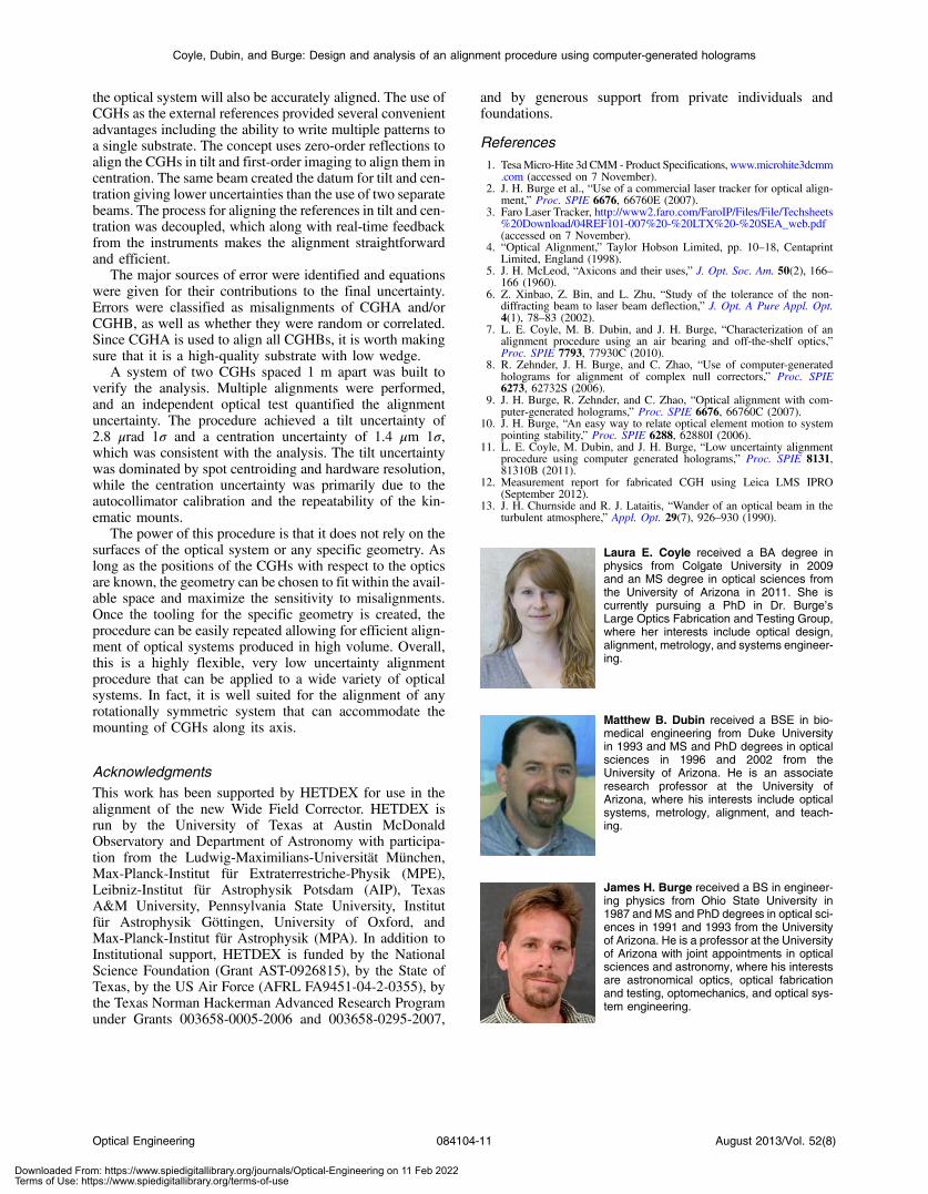
Laura E. Coyle received a BA degree inphysics from Colgate University in 2009and an MS degree in optical sciences fromthe University of Arizona in 2011. She iscurrently pursuing a PhD in Dr. Burge’sLarge Optics Fabrication and Testing Group,where her interests include optical design,alignment, metrology, and systems engineer-ing.
Matthew B. Dubin received a BSE in bio-medical engineering from Duke Universityin 1993 and MS and PhD degrees in opticalsciences in 1996 and 2002 from theUniversity of Arizona. He is an associateresearch professor at the University ofArizona, where his interests include opticalsystems, metrology, alignment, and teach-ing.
James H. Burge received a BS in engineer-ing physics from Ohio State University in1987 and MS and PhD degrees in optical sci-ences in 1991 and 1993 from the Universityof Arizona. He is a professor at the Universityof Arizona with joint appointments in opticalsciences and astronomy, where his interestsare astronomical optics, optical fabricationand testing, optomechanics, and optical sys-tem engineering.
Optical Engineering 084104-11 August 2013/Vol. 52(8)
Coyle, Dubin, and Burge: Design and analysis of an alignment procedure using computer-generated holograms
Downloaded From: https://www.spiedigitallibrary.org/journals/Optical-Engineering on 11 Feb 2022Terms of Use: https://www.spiedigitallibrary.org/terms-of-use


![Alignment and Installation Procedure for UW Eqpts[1]](https://img.dokumen.tips/doc/110x75/5477ff405906b57d318b46f6/alignment-and-installation-procedure-for-uw-eqpts1.jpg)

