Embed Size (px)
Citation preview

University of Mississippi University of Mississippi
eGrove eGrove
Honors Theses Honors College (Sally McDonnell Barksdale Honors College)
Spring 5-1-2021
Design and Analysis of a Process to Convert Methanol into Design and Analysis of a Process to Convert Methanol into
Dimethyl Ether Dimethyl Ether
Elisa M. White University of Mississippi
Follow this and additional works at: https://egrove.olemiss.edu/hon_thesis
Part of the Catalysis and Reaction Engineering Commons, and the Other Chemical Engineering
Commons
Recommended Citation Recommended Citation White, Elisa M., "Design and Analysis of a Process to Convert Methanol into Dimethyl Ether" (2021). Honors Theses. 1885. https://egrove.olemiss.edu/hon_thesis/1885
This Undergraduate Thesis is brought to you for free and open access by the Honors College (Sally McDonnell Barksdale Honors College) at eGrove. It has been accepted for inclusion in Honors Theses by an authorized administrator of eGrove. For more information, please contact [email protected].

i
DESIGN AND ANALYSIS OF A PROCESS TO CONVERT METHANOL INTO DIMETHYL
ETHER
By
Elisa Maria White
A thesis submitted to the faculty of The University of Mississippi in partial fulfillment of the
requirement of the Sally McDonnell Barksdale Honors College.
Oxford
May 2021
Approved by
____________________________________
Advisor: Professor Adam Smith
____________________________________
Reader: Professor Mike Gill
____________________________________
Reader: Professor David Carrol

ii
© 2021
Elisa Maria White
ALL RIGHTS RESERVED

iii
ACKNOWLEDGEMENTS
I would like to thank my teammates MaKensie Barbee, Brennen Middleton, and Jasmine Stevens
for their hard work on this project and for helping me in my thesis defense presentation. I would
also like to thank the Sally McDonnell Barksdale Honors College and Department of Chemical
Engineering for their continued support during this process.

iv
ABSTRACT
A recent economic downturn led to the loss of a contract for a company that sells methanol. The
company has two options to recover some of the profit lost from the contract termination. One
option is to sell the excess methanol at the spot market price, and the second option is to implement
a process to convert the excess methanol into dimethyl ether. This project investigated the
implementation of a process to convert the methanol from the lost contract into dimethyl ether.
The process was simulated in AVEVA Process Simulation to estimate the size of equipment
needed. A toller provided a list of equipment available to rent, that was similar in size to the
estimated equipment in the base case, for the process consisting of three reactors, three distillation
columns, and eight heat exchangers. Twelve viable equipment combinations consisting of one
reactor, one column, and five heat exchangers each were identified. The least costly equipment set
was determined through optimization of the viable equipment combinations. The annual cost of
the rental and utilities for the most profitable combination was determined to be $662,000. The
profit from the dimethyl ether produced was calculated to be $6.4 million dollars when the rental
and utility costs for the process were deducted. This option would earn the company an extra $1.2
million in profit compared to selling the methanol on the open market for $5.2 million. Dimethyl
ether production was concluded to be the most profitable option for the company.
v
TABLE OF CONTENTS
ACKNOWLEDGEMENTS ............................................................................................... iii
ABSTRACT ....................................................................................................................... iv
TABLE OF CONTENTS .................................................................................................... v
LIST OF FIGURES ........................................................................................................... vi
LIST OF TABLES ............................................................................................................ vii
Introduction ....................................................................................................................... 1
DME Production Process ................................................................................................. 1
Environmental and Process Safety Considerations ....................................................... 2
AVEVA Process Simulation ............................................................................................. 4
Base Case ........................................................................................................................... 5
Equipment Selection and Viability .................................................................................. 7
Optimization of Equipment Combinations .................................................................... 9
Economic Analysis ............................................................................................................ 9
Conclusions and Recommendations .............................................................................. 12
LIST OF REFERENCES ............................................................................................... 13
Appendix ......................................................................................................................... 14

vi
LIST OF FIGURES
Equation 1…………………………………….…………………………………………………...1
Figure 1: NFPA Diamonds for Methanol and DME……………………………………………....2
Figure 2: 3D Graph of DME Column Optimization Parameters: Number of Stages, Feed Location,
and EAOC………………………………………………………………………………………....7
Figure A-1: Process Flow Diagram for the conversion of methanol to dimethyl
ether………………………………………………………………………………………………14
Figure A-2a: Optimized Toller Equipment Combinations 1-6……………...……………………17
Figure A-2b: Optimized Toller Equipment Combinations 7-12………………………………….18

vii
LIST OF TABLES
Table 1: Yearly Costs for Equipment Combinations…………………………….……………….10
Table 2: Potential Profit from Open Market Sale…………………………………………………11
Table A-1: Equipment Specifications for Optimized Base Case……………………….…………15
Table A-2: Stream Table for Optimized Base Case………………………………………………15
Table A-3a: Available Reactors and Columns……………………………………………………16
Table A-3b: Available Heat Exchangers…………………………………………………………16

1
Introduction
A chemical company that produces commercial grade methanol has lost a long term contact due
to a significant economic downturn in the last year. This leaves the company in a difficult situation.
Two options have been proposed. The first option would be to sell the methanol on the open
market, but due to a glut of methanol in the local market, the spot selling price for methanol is
likely to be low. A second solution has been suggested involving the conversion of the excess
methanol into dimethyl ether (DME). The DME production process shall occur on a rented, skid-
mounted unit provided by a toller, who is an outside contractor. This installment is not permanent,
and if the decision is made to halt production of DME, the toller has agreed to safely remove the
equipment. There is a shortage of DME in the local market which means that the spot selling price
for DME is higher than that of methanol.
Option three has the potential for a higher profit, due to the larger market demand for DME than
for methanol. Design and analysis of the process to convert methanol into DME was completed to
investigate the incentive for implementing this process.
DME Production Process
Dimethyl ether is produced by the catalytic dehydration of methanol. Vaporized methanol is fed
into a packed bed reactor (PBR) of catalyst where the reversible reaction takes place as shown in
Equation 1.
𝐶𝐻3𝑂𝐻 ↔ (𝐶𝐻3)2𝑂 + 𝐻2𝑂 (1)

2
The other important unit operation in this process is distillation. The distillation column separates
the water and unreacted methanol from the DME product. For this process to be successful, the
single pass conversion of methanol in the reactor must reach 81% or higher, with a recycle stream
being utilized for the unreacted methanol. This methanol will be returned to the methanol feed and
sent back through the process. The product purity of DME must be 99.5% by weight. Dimethyl
ether (DME) is used extensively in the chemical industry as an aerosol propellant for products
such as hair spray and bug spray. Furthermore, it can be used in specially designed compression
ignition diesel engines and creates less emissions than standard automotive fuels.
Environmental and Process Safety Considerations
Methanol and DME have separate safety and environmental considerations. First, the National Fire
Protection Association (NFPA) diamonds were considered for both chemicals to determine the
safety considerations for our operators and process. The diamonds are shown in Figure 1 [1, 2].
Figure 1: NFPA Diamonds for Methanol and DME
Methanol has a fire hazard of 3. This means that methanol has a flash point below 100°F. Methanol
has a closed-cup flash point of 54°F and is highly flammable. Additionally, methanol has a health

3
hazard of 1, which means that methanol slightly hazardous. Methanol is toxic if inhaled, ingested,
or contacts skin. Additionally, methanol can cause adverse kidney and liver effects, can be fatal or
cause blindness if swallowed, and can cause headache, nausea, and shortness of breath. Finally,
methanol has a reactivity hazard of 0, meaning it is stable [3].
DME has a fire hazard of 4, which means it has a flash point below 73°F. DME is a gas at room
temperature and can be stored in gas phase, or it can be stored as a liquid in a pressurized vessel
much like propane. DME has a closed-cup flash point of -42°F and is highly flammable. Specific
storage instructions should be discussed with a subject matter expert to ensure safe storage
practices are in place. Additionally, DME has a health hazard of 2, which means it is hazardous.
DME will cause nervous system depression if inhaled or swallowed and can cause drowsiness,
dizziness, nausea or vomiting, headache, and unconsciousness. Finally, DME has a reactivity
hazard of 1. This means DME can become unstable if heated. It should be noted that DME can
react with oxygen to create explosive peroxides. When explosive peroxides are created or the DME
is liquified, the DME becomes unstable when heated, but it is not unstable in pure form [4].
With these risks known, several safety precautions should be implemented to ensure safe handling
of these chemicals. First, all operators and employees should wear proper personal protective
equipment (PPE) when handling these chemicals or process equipment. This includes eye
protection, gloves, and a respirator with an organic filter if proper ventilation is not available.
Additionally, DME is peroxidizable, so DME should be stored in an opaque container, a peroxide
inhibitor, such as hydroquinone, should be added to the DME storage tank, and a nitrogen blanket
should be used in the storage tank to reduce peroxide formation. Furthermore, sources of ignition
should be minimized, and proper fire safety should be implemented to reduce the risk of a fire and
minimize the damage caused by a fire. Finally, methanol exists as a liquid at room temperature,
4
and DME exists as a vapor at room temperature. Thus, storage requirements for these chemicals
will differ, as methanol may be stored as a liquid in a vessel, but DME will either need to be
compressed in gas cylinders or held in pressurized vessels for storage [3, 4].
DME has no known environmental hazards. However, it is recommended to consult local and
federal guidelines for disposal. It is recommended that a flare system be utilized in the event DME
must be vented to the environment. Methanol, however, is toxic to aquatic ecosystems and is highly
mobile in soil and water. Thus, it is important that methanol not be released into the environment
and is disposed of based on local and federal regulations [3, 4].
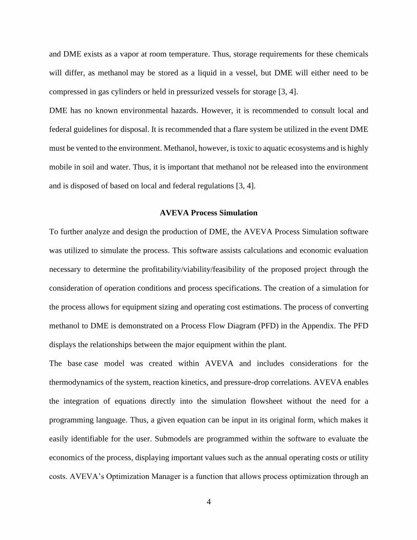
AVEVA Process Simulation
To further analyze and design the production of DME, the AVEVA Process Simulation software
was utilized to simulate the process. This software assists calculations and economic evaluation
necessary to determine the profitability/viability/feasibility of the proposed project through the
consideration of operation conditions and process specifications. The creation of a simulation for
the process allows for equipment sizing and operating cost estimations. The process of converting
methanol to DME is demonstrated on a Process Flow Diagram (PFD) in the Appendix. The PFD
displays the relationships between the major equipment within the plant.
The base case model was created within AVEVA and includes considerations for the
thermodynamics of the system, reaction kinetics, and pressure-drop correlations. AVEVA enables
the integration of equations directly into the simulation flowsheet without the need for a
programming language. Thus, a given equation can be input in its original form, which makes it
easily identifiable for the user. Submodels are programmed within the software to evaluate the
economics of the process, displaying important values such as the annual operating costs or utility
costs. AVEVA’s Optimization Manager is a function that allows process optimization through an

5
iterative calculation method. Certain variables can be changed and/or constrained in order to
satisfy an objective function (i.e., minimize total utility costs or equivalent annual operating
costs).
There are three simulation modes available in the program: Process, Fluid Flow, and Dynamics.
Process mode is used to perform steady-state mass and energy balances that will allow for the
design and sizing of process equipment. Fluid Flow mode can also be used for steady-state
calculation but is primarily driven by the fluid dynamics within the system. It evaluates the sizes
of valves, pipes, vessels, and heat exchangers. Dynamics mode evaluates processes over time and
should be used to develop control systems that respond to deviations from the base case, such as a
sudden change in flow, pressure, temperature, or liquid levels. For the creation of the base case
model, the simulation was completed using the Process mode in order to focus on designing the
key pieces of equipment for the DME process (reactor, column, and heat exchangers). This
simplified the initial design to determine whether the project should move forward and be further
investigated for profitability.
Base Case
The PFD of the process, shown in Figure A-1, was utilized to develop the base case simulation for
the DME production facility. This base case simulation modeled unit operations for two major
equipment groups. The reactor, a packed bed reactor (PBR), and the separations unit, a trayed
distillation column, along with associated equipment, such as heat exchangers and pumps, to
provide the necessary stream properties for the process streams.
The creation of the base case model was executed to accomodate the required annual feed rate of
methanol (23,000 tonne/y), along with the recycled unreacted methanol from the process, the

6
desired purity of DME (99.5 wt%), and the desired single-pass conversion of methanol to DME
(≥81%). This model served as a preliminary design that corresponds with the PFD.
To simulate the base case, each stream and unit operation shown on the PFD was placed in the
flowsheet in order from left to right. First, the feed conditions were specified. The given
temperature, pressure, and flowrate of methanol to the process were entered into the simulation.
From there, the equipment was added and specified according to the given parameters and
requirements. Submodels were used to calculate reaction kinetics in the reactor along with pressure
drop correlations. Some important parameters for equipment were not specified, such as lengths
and diameters, so they were calculated by the program based on the information that was added to
the simulation. Once all the streams and equipment on the PFD were on the flowsheet, the
simulation was solved with no error messages and all unspecified values were calculated by the
program.
Next, the base case distillation column was optimized to complete the base case analysis. The
initial design was optimized to minimize the Equivalent Annual Operating Costs (EAOC)
associated with the distillation column, including the condenser and reboiler. Costs associated with
the column’s auxiliary equipment were considered negligible for these calculations. The EAOC
was calculated as a function of the purchase costs of the distillation column, columns trays, the
condenser, and the reboiler. The cost of the column is related to its volume, the cost of the trays is
related to the column’s cross-sectional area, and the cost of the exchangers (condenser and
reboiler) are related to the required heat exchange area.
Parameters for feed tray location and number of column trays were changed to minimize the EAOC
in order to determine the approximate minimum size of equipment that could be used for the

7
process. These equipment specification and design estimates were compiled, as shown in Table
A-1. The optimized operating point for the DME column is represented in Figure 2 as a 3D graph.
Figure 2: 3D Graph of DME Column Optimization Parameters: Number of Stages, Feed
Location, and EAOC
The optimal column configuration had 15 trays with the feed coming into the column at tray 15.
With the tower optimized, the base case was complete. Table A-2 shows the data for all process
streams in the optimized base case.
Equipment Selection and Viability
After completion of the base case simulation and EAOC optimization, equipment sizing results
were sent to the toller. From these results, the toller determined available equipment that could be
utilized for the process. Three reactors, three columns, and eight heat exchangers were presented
by the toller for consideration. The equipment presented is shown in Tables A-3a and A-3b. These

8
include the size of the equipment and relevant equipment parameters, such as the maximum
allowable working pressure (MAWP), maximum allowable working temperature (MAWT), and
number of column trays. Additionally, some considerations were given by the toller to allow for
simulation of these units while upholding the required operation parameters. These are shown in
Table A-3a and are noted via asterisks to indicate the requirements and/or considerations.
To begin the simulation of the equipment, the possible reactor and column combinations available
were considered first. As there were three reactors and three columns available, a maximum of
nine reactor-column combinations could be created. These combinations were analyzed, without
the specification of available heat exchangers, to determine if the combinations were viable with
the required equipment specifications.
From this analysis, it was determined that column B would not be operable for the process. This
was due to two interconnected reasons. The first was due to the MAWP of the column, which was
7 bar. As the process operates at 10 bar under base case operating conditions, it was found from
the analysis that a MAWP of 7 bar for the distillation column was too low for operating procedures.
Additionally, due to the low pressure in the distillation column, the condenser attached to the
distillate portion of the column increased to a value that was unreasonably large for the process.
With no heat exchanger large enough to accommodate for the size needed for the condenser, a
secondary reason for the discontinuation of simulating with column B was provided.
With the elimination of column B, six combinations of reactors and columns were utilized in
combination with the available heat exchangers to determine all viable combinations. By changing
the heat exchangers, utilities used for the heat exchangers, and the stream conditions in the plant,
twelve viable equipment combinations were identified.

9
Optimization of Equipment Combinations
Once the equipment combinations were modeled, each simulation was optimized to achieve the
lowest possible utility costs. The cost of utilities included the electricity powering the two pumps
as well as the cost of low, medium, and high-pressure steam, cooling water, and refrigerated
cooling water used in the heat exchangers. Using the economic submodel in AVEVA Process
Simulation, the hourly cost of the utilities was calculated. To perform the minimization of utility
costs, the optimization function in AVEVA Process Simulation was used. In the optimization
manager, the goal was set to minimize the cost of utilities. The variables for the optimization were
process stream temperature into the column as well as pressure and tray diameter of the column,
and the minimum and maximum allowable values for these variables was also specified.
Additionally, constraints were set for the optimization based on the required flooding factor in the
column being between 30% and 80% for each tray. The maximum allowable temperature within
the column, as seen in Table A-3a, was also used as a constraint. The optimization was run for
each of the 12 equipment combinations, and the minimum possible utility cost for each simulation
was reached.
Economic Analysis
With the utility costs calculated for the 12 equipment combinations, the economic analysis was
completed. The yearly rental costs of the equipment and the utility costs per year for each
combination were added to determine the overall cost per year. Figures A-2a and A-2b show the
breakdown of yearly costs for the equipment and utilities for each combination. The yearly cost
for the 12 combinations ranged from $662,016 to $919,003 per year. Rental costs for equipment

10
from the toller contributed more to the overall yearly cost than the utilities. The range in rental
costs for the combinations was $278,280, while the range in utility costs was only $47,718. The
yearly cost, from least to greatest for each of the 12 equipment combinations is shown in Table 1.
Table 1: Yearly Costs for Equipment Combinations
Equipment
Combination Yearly Cost Reactor/Column Heat Exchangers*
1 $662,000 B/A D,B,C,F,G
2 $678,000 A/A D,B,C,A,G
3 $681,000 A/A D,B,C,F,G
4 $803,000 C/A F,B,C,D,G
5 $834,000 C/A F,B,C,A,G
6 $835,000 C/A A,B,C,H,G
7 $841,000 C/A A,B,C,E,G
8 $857,000 C/C A,B,C,D,G
9 $860,000 C/C F,B,C,D,G
10 $889,000 A/C F,B,C,A,G
11 $890,000 C/C F,B,C,A,G
12 $919,000 C/C A,B,C,E,G *in order E-101, E-102, ..., E-105
Note that the exchangers chosen for E-102, E-103, and E-105 were the same for each combination.
This is because, for E-102 and E-103, these exchangers were the only options that could operate
at the high pressure and temperature, respectively. As for E-105, heat exchanger G was used
because the smallest heat exchange area was needed for the reboiler.
The most expensive reactor and column combination was reactor C and column C at a price of
$919,000 per year. This reactor and column combination, when paired with different heat
exchanger options, made up four of the five most expensive combinations. Interestingly, the most
expensive utility costs were found in the combination that was the least expensive overall. Reactor

11
B, column A was the equipment combination that was the least expensive at a price of $662,000
per year. This is largely due to the rental costs of reactor B and column A being the smallest out
of the available equipment. Even though the utility costs for this configuration were the highest
out of all the configurations, the use of the lowest cost reactor and column compensated for the
larger utility cost. This equipment combination also achieved an 84% conversion of methanol,
which exceeded the required minimum of 81% conversion.
The profit from selling the excess methanol on the open market compared to the profit if the excess
methanol is converted into DME, after rental and utility costs are subtracted, is shown in Table 2:
Table 2: Potential Profit from Open Market Sale
Sale Type Profit ($M/yr)
Open Market Methanol 5.2
Open Market DME 6.4
The company would increase their profit by $1.2 million per year if the DME process was
implemented. This estimate, however, does not include deductions for costs like labor,
maintenance, taxes, etc. More analysis would have to be done to determine the actual final profit
when all costs are accounted for.

12
Conclusions and Recommendations
Converting the methanol from the lost contract into DME is a profitable option for the
company. A base case model was successfully created to meet the required annual feed rate of
methanol (23,000 tonne/y), the desired purity of DME (99.5 wt%), and the desired single-pass
conversion of methanol to DME (≥81%). With this base case model, equipment sizing was
estimated in order to obtain a list of equipment that could work for the process from the toller.
Based on the equipment list provided by the toller, the DME conversion can be completed for an
equipment rental and utility cost of $662,000 per year. A profit of $6.4 million per year can be
made using the equipment combination shown in Table 2.
Before the process can be successfully implemented, there are two important steps that need to be
taken. First, a dynamic simulation should be developed in AVEVA Process Simulation. In a
dynamic simulation, a control system can be implemented and tested. The process needs to be
tested for its ability to adapt to small changes in temperature, pressure, or flow rate that are
common in production. If the system is unable to adapt quickly and adequately, the process is not
viable. Second, a full net present value (NPV) analysis should be conducted to account for costs
not covered in this project. This analysis will ensure that the process would still be profitable when
every cost is considered.

13
LIST OF REFERENCES
[1] National Library of Medicine. “Dimethyl Ether.” [Online]. Available from
https://webwiser.nlm.nih.gov/substance?substanceId=184&identifier=Dimethyl%20Ether&identi
fierType=name&menuItemId=47&catId=56
[2] National Library of Medicine. “Methanol.” [Online]. Available from
https://webwiser.nlm.nih.gov/substance?substanceId=19&identifier=Methanol&identifierType=n
ame&menuItemId=47&catId=56
[3] Global Safety Management, Inc. (2015). “Methanol Safety Data Sheet.” [Online]. Available
from https://beta-
static.fishersci.com/content/dam/fishersci/en_US/documents/programs/education/regulatory-
documents/sds/chemicals/chemicals-m/S25426A.pdf
[4] Airgas. (2019). “Dimethyl Ether Safety Data Sheet.” [Online]. Available from
https://www.airgas.com/msds/001021.pdf

14
Appendix
Figure A-1: Process Flow Diagram (PFD) for the conversion of methanol to dimethyl ether (DME)

15
Table A-1: Equipment Specifications for Optimized Base Case
Table A-2: Stream Table for Optimized Base Case

16
Table A-3a: Available Reactors and Columns
Table A-3b: Available Heat Exchangers

17
Figure A-2a: Optimized Toller Equipment Combinations 1-6

18
Figure A-2b: Optimized Toller Equipment Combinations 7-12