Embed Size (px)
Citation preview

Copyright is owned by the Author of the thesis. Permission is given for a copy to be downloaded by an individual for the purpose of research and private study only. The thesis may not be reproduced elsewhere without the permission of the Author.
Design and analysis of a novel piezoelectric rotary motor
with the cyclic symmetric stator
Master of Engineering
In
Mechatronics
By
Hong-Yi Cheng
School of Engineering and Advanced Technology
Massey University
New Zealand
2011
i
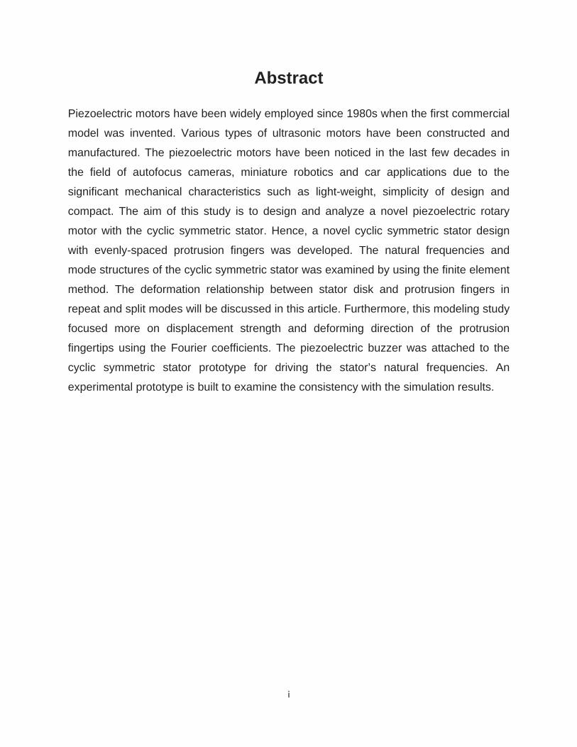
Abstract
Piezoelectric motors have been widely employed since 1980s when the first commercial
model was invented. Various types of ultrasonic motors have been constructed and
manufactured. The piezoelectric motors have been noticed in the last few decades in
the field of autofocus cameras, miniature robotics and car applications due to the
significant mechanical characteristics such as light-weight, simplicity of design and
compact. The aim of this study is to design and analyze a novel piezoelectric rotary
motor with the cyclic symmetric stator. Hence, a novel cyclic symmetric stator design
with evenly-spaced protrusion fingers was developed. The natural frequencies and
mode structures of the cyclic symmetric stator was examined by using the finite element
method. The deformation relationship between stator disk and protrusion fingers in
repeat and split modes will be discussed in this article. Furthermore, this modeling study
focused more on displacement strength and deforming direction of the protrusion
fingertips using the Fourier coefficients. The piezoelectric buzzer was attached to the
cyclic symmetric stator prototype for driving the stator’s natural frequencies. An
experimental prototype is built to examine the consistency with the simulation results.

ii
Acknowledgement
Studying toward to Master degree in Massey has been the most important and
extraordinary experience in my life. This training progress has improved the way of my
thinking and ability of solving problems.
I would like to thank my thesis adviser Dr. Jen-Yuan (James) Chang whose expertise,
advice and continuous support during the research. I consider myself extremely
fortunate to work under his supervision.
I would also like to thank Dr. Johan Potgieter, Eddie Rogers, Paul Thornton and Joe
Wang for the manufacturing support. Also, I felt gratitude to the faculty staff for their
help and Massey University staff for their various support during the study.
I am further indebted to current and past colleagues (Rana Noman Mubarak, Amur
Alminji, Hamid Reza Memarbashi, Riichi Nagao, Ivan Ernesto Cortes Zambrano, Di Wu
and Jason Li) in my research lab for their valuable feedback and knowledge.
Finally, I would like to express my appreciation to my parents and other family members
who have provided continuous encouragement and support to all my educational
pursuits. They have helped me go through the challenges along the way. I certainly
wouldn’t have made it this far without them.

iii
Table of Contents
Chapter 1 Introduction .................................................................................................. 1-1
1.1. Piezoelectric Motor .......................................................................................... 1-1
1.2. Applications ..................................................................................................... 1-2
1.3. Scope and contribution ................................................................................. 1-10
1.4. Thesis Outline ............................................................................................... 1-10
Chapter 2 Fundamental of piezoelectricity theory ........................................................ 2-1
2.1. Chapter Overview ........................................................................................... 2-1
2.2. The phenomenon of piezoelectricity ................................................................ 2-1
2.3. Piezoelectric Materials .................................................................................... 2-3
2.4. Piezoelectric Actuator ..................................................................................... 2-6
Chapter 3 System configuration ................................................................................... 3-1
3.1. Chapter Overview ........................................................................................... 3-1
3.2. Model Description ........................................................................................... 3-1
3.2.1. Rotor ........................................................................................................... 3-3
3.2.2. Stator .......................................................................................................... 3-3
3.2.3. Piezoelectric ceramic buzzer ...................................................................... 3-5
3.2.4. Base ............................................................................................................ 3-5
3.3. Finite Element Analysis ................................................................................... 3-5
3.4. Chapter summary .......................................................................................... 3-12
Chapter 4 Parametric study of cyclic symmetric stator ................................................. 4-1
4.1. Chapter Overview ........................................................................................... 4-1
4.2. Parametric study ............................................................................................. 4-1
4.2.1. Displacement variation with varying contact angle ..................................... 4-2
4.2.2. In-plane deformation angle with varying contact angle ............................... 4-8
4.3. Chapter summary .......................................................................................... 4-13
Chapter 5 Experimental result ...................................................................................... 5-1
5.1. Experimental setup ......................................................................................... 5-1
5.2. Experimental result ......................................................................................... 5-3
5.3. Chapter summary ............................................................................................ 5-6

iv
Chapter 6 Summary ..................................................................................................... 6-1
6.1. Structure response in a novel cyclic symmetric stator model .......................... 6-1
6.2. Displacement strength and in-plane deformation angle of the cyclic symmetric
stator ............................................................................................................... 6-2
6.3. Limitations ....................................................................................................... 6-2
6.4. Directions for future work ................................................................................ 6-3
Reference .................................................................................................................... R-1
Appendix ...................................................................................................................... A-1
v
List of Figures
Figure 1: Fundamental construction of Barth motor (1: rotor, 2: shaft, 3: active element,
4: piezoelectric plate) ................................................................................................... 1-3
Figure 2: (a) Piezo Systems Ultrasonic Motor (Shinsei USR30) and (b) Traveling Wave
Formation ..................................................................................................................... 1-5
Figure 3: Auditory tele-existence robot TeleHead ........................................................ 1-7
Figure 4: Mechanism of TeleHead II ............................................................................ 1-7
Figure 5: Design of multi-DOF surgical instrument ....................................................... 1-8
Figure 6: Master–slave system for surgical instrument ................................................ 1-9
Figure 7: Direct Piezoelectric Effect ............................................................................. 2-2
Figure 8: Converse Piezoelectric Effect ....................................................................... 2-2
Figure 9: Perovskite structure ...................................................................................... 2-3
Figure 10: Polarization of crystals ................................................................................ 2-4
Figure 11: Polarization of the piezoelectric ceramic domains ....................................... 2-5
Figure 12: The polling process ..................................................................................... 2-5
Figure 13: Schematic view of a piezoelectric buzzer .................................................... 2-6
Figure 14: Structure of the piezoelectric rotary motor................................................... 3-2
Figure 15: schematic of the cyclic symmetric stator ..................................................... 3-4
Figure 16: Mesh of the cyclic symmetric stator model with boundary condition ........... 3-6
Figure 17: Simulation result from Solidworks (Mode Shape 1~5) ................................. 3-8
Figure 18: Simulation result from Solidworks (Mode Shape 6~10) ............................... 3-9
Figure 19: Modified cyclic symmetric stator with 4 and 6 evenly-spaced protrusion
fingers in P(0,2) and P(0,3) respectively .................................................................... 3-11
Figure 20: Contact angle at 0° - (a) nodal patterns and (b) the displacement strength of
protrusion fingertips. (c) the corresponding Fourier coefficients ................................... 4-3
Figure 21: Contact angle at 30° - (a) nodal patterns and (b) the displacement strength of
protrusion fingertips. (c) the corresponding Fourier coefficients ................................... 4-4
Figure 22: Contact angle at 45° - (a) nodal patterns and (b) the displacement strength of
protrusion fingertips. (c) the corresponding Fourier coefficients ................................... 4-5
vi
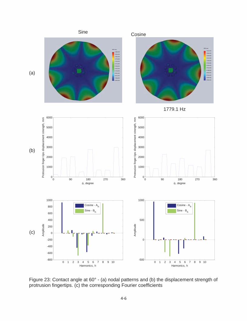
Figure 23: Contact angle at 60° - (a) nodal patterns and (b) the displacement strength of
protrusion fingertips. (c) the corresponding Fourier coefficients ................................... 4-6
Figure 24: Contact angle at 0° - Protrusion fingertips deformed angle in (a) sine and (b)
cosine oriented components ...................................................................................... 4-10
Figure 25: Contact angle at 30° - Protrusion fingertips deformed angle in (a) sine and (b)
cosine oriented components ...................................................................................... 4-11
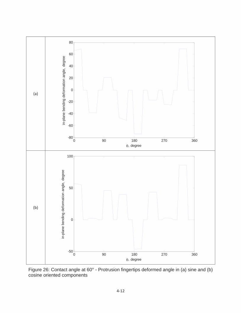
Figure 26: Contact angle at 60° - Protrusion fingertips deformed angle in (a) sine and (b)
cosine oriented components ...................................................................................... 4-12
Figure 27: Piezoelectric rotary motor experimental setup ............................................ 5-2
Figure 28: Chlandi-type measurement used on the cyclic symmetric stator ................. 5-4
Figure 29: Rotation performance .................................................................................. 5-5
Figure 30: 0° disk edge displacement and corresponding harmonic ............................ A-6
Figure 31: 15° disk edge displacement and corresponding harmonic .......................... A-7
Figure 32: 30° disk edge displacement and corresponding harmonic .......................... A-8
Figure 33: 45° disk edge displacement and corresponding harmonic .......................... A-9
Figure 34: 60° disk edge displacement and corresponding harmonic ........................ A-10
Figure 35: 0° finger base displacement and corresponding harmonic ........................ A-11
Figure 36: 15° finger base displacement and corresponding harmonic ...................... A-12
Figure 37: 30° finger base displacement and corresponding harmonic ...................... A-13
Figure 38: 45° finger base displacement and corresponding harmonic ...................... A-14
Figure 39: 60° finger base displacement and corresponding harmonic ...................... A-15

1 1
Chapter 1
Introduction
1.1. Piezoelectric Motor
Nowadays, the size minimization of electrical drives used in small-scale actuation has
become an important design issue. Several applications, such as micro-satellite, micro-
robot actuation and servo-drives used in the field, require operation at high torque and
low speed. Most electric drives use electromagnetic motors due to the operation
principles are well understood and the designs are optimized for a variety of
applications. High torque at low speed is achieved by using a gear reduction unit, which
leads to an increase in the size and mass of the drive. Electromagnetic motors use a
magnetic field to generate torque; however, these motors cannot operate if a strong
external magnetic field is presented, as their rotor will lock on the direction of the
external magnetic field. The electromagnetic motor is limited in this aspect without new
findings on new designs or materials. Therefore, the attention of researchers and
engineers turned to a new type of motor – “piezoelectric motor.”
The piezoelectric motor became well-known and appeared in high numbers in
commercial products since 1980s, and opened a new horizon in the field of small
electric drives due to specific advantages, this type of motor possesses over the
classical electromagnetic motor. Piezoelectric motors are also known as ultrasonic
motors. The term of “ultrasonic” is for the reason that the drive frequencies of these
motors are in the range of 25 to 70 kHz. The main characteristics and advantages of
this type of motor are:

1 2
a high torque at low speed without using a gear [1]
a simple redesign by providing additional piezoelectric material mounted on the
same stator
the ability to operate in a vacuum
the ability to operate in strong magnetic fields
silent operation due to the fact that the excitation signals are at ultrasonic
frequencies
a simpler construction than electromagnetic motors and simple manufacturing
process
Ultrasonic motors have widest range of applications. For example, It has been used in
the automotive industry for headrest and seat adjustment, for the rotational scanning
mount of a television camera, for auto focusing in Canon cameras and last but not least
for micro-robot actuators [2]-[3].
1.2. Applications
There are several successful applications and research prototypes around the world of
piezoelectric motors. Some applications, research and prototypes will be reviewed in
the following paragraphs.
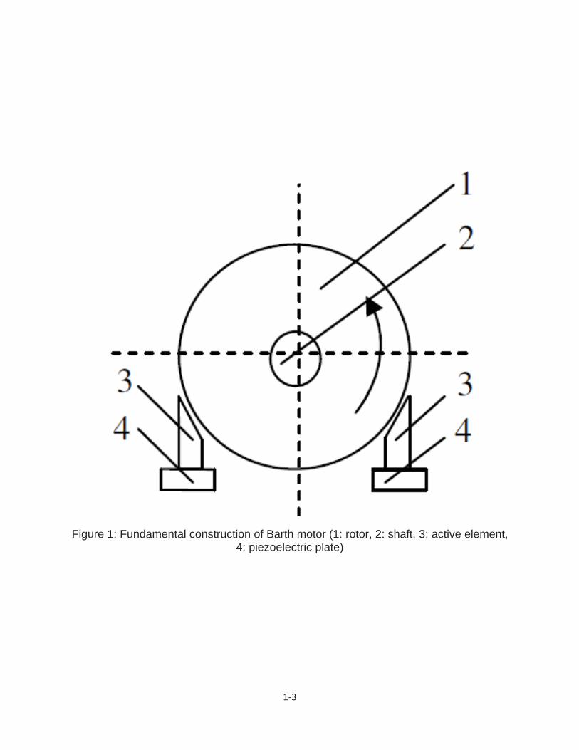
The earliest attempt of ultrasonic motor (as shown in Figure 1) was proposed by H V
Barth of IBM in 1973 [4]. The rotor was loaded against two horns placed at different
locations. By exciting one of the horns, the rotor was driven in one direction, and by
exciting the other horn, the rotation direction was reversed. Based on the same principle,
many mechanisms were proposed [5]-[6]. However, the motors were not of many
practical uses at that time due to the difficulty in maintaining constant vibration
amplitude with temperature rise, wear and tear.
1 3
Figure 1: Fundamental construction of Barth motor (1: rotor, 2: shaft, 3: active element, 4: piezoelectric plate)
1 4
Later on, Sahida designed and made a standing wave ultrasonic motor which used a
Langevin vibrator. The driving frequency of this motor was 27.8 kHz with input electric
power of 90W, output mechanical power of 50W, output torque of 0.5N·m, output
rotational speed of 2800 rpm/min, and the efficiency was 60%. This motor’s metal film
and the rotor were fixed at the same position and serious wears existed on the contact
surfaces. It was believed that this piezoelectric ultrasonic motor met the performance
requirements for actual applications at the first time.
In 1982, the mechanism, the traveling-wave ultrasonic motor [1] (TWUSM) was invented
by Toshiiku Sashida of Shinsei Co. Ltd. of Japan. This model has improved the problem
of wear between the stator and the rotor- and Shinsei licensed the ensuring patent to
Canon. Thus, in 1985, Canon introduced the ring USM drive on its EF 300 mm f/2.8L
USM lens established on the ultrasonic motor technology. This ultrasonic motor became
the first commercial ultrasonic motor. In addition to the use of the principle in lenses,
Canon also offered a wide line of ultrasonic motors for industrial, scientific, and
consumer goods applications. Since ultrasonic motors developed by Sashida were
commercialized, this new concept motor aroused the interest of engineers and
researchers. Various ultrasonic motors with different exciting principles, structures and
performances have been developed [7]-[11]. On the basis of the vibration mode,
ultrasonic motors can be categorized into either standing wave ultrasonic motor or
travelling wave ultrasonic motor. The detailed examples of these two types of ultrasonic
motor will be introduced in the following section:
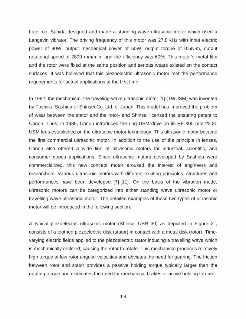
A typical piezoelectric ultrasonic motor (Shinsei USR 30) as depicted in Figure 2 ,
consists of a toothed piezoelectric disk (stator) in contact with a metal disk (rotor). Time-
varying electric fields applied to the piezoelectric stator inducing a travelling wave which
is mechanically rectified; causing the rotor to rotate. This mechanism produces relatively
high torque at low rotor angular velocities and obviates the need for gearing. The friction
between rotor and stator provides a passive holding torque typically larger than the
rotating torque and eliminates the need for mechanical brakes or active holding torque.
1 5
(a)
(b)
Figure 2: (a) Piezo Systems Ultrasonic Motor (Shinsei USR30) and (b) Traveling Wave Formation

1 6
These motors can be built without producing or being affected by magnetic fields,
making them useful in highly magnetic environments and applications in which magnetic
fields are harmful. Nevertheless, the state of the art in control of piezoelectric ultrasonic
motors (PUM) is not fully developed. Commercial motors typically employ open-loop
speed controllers which are operated in cascade with non-model-based control
schemes such as proportional-integral-derivative control. These techniques are effective
and appropriate for many applications for example, the locomotion. Also, the techniques
are not suitable for precise positioning, or for mission-critical applications requiring
guaranteed stability and performance characteristics. The goal of PUM research
conducted in the University of Houston – Clear Lake (UHCL) Systems Engineering
Laboratory is to develop model-based real-time control algorithms for PUM. Supportive
research of ISSO entailed characterizing the kinematic performance of a commercial
variable-frequency motor driver and designing a custom driver that provides greater
variations in driving signal frequency as well as variable driving signal amplitude.
TeleHead [12] is a prototype of ultrasonic motor application which is developed as a test
bed of a new sophisticated telecommunications tools. By introducing tele-existence
technology, the TeleHead can transmit real sound fields of a remote place to the user,
giving the user a feeling of being at a remote place. The “TeleHead I” (Figure 3) and
“TeleHead II” (Figure 4) was built in 2001 and 2003 respectively. TeleHead has a
dummy head that has the same head-related transfer function (HRTF) as the head of its
remote user. Remote users can localize the sound source by listening to the sound
received by microphones installed in the dummy head. The dummy head tracks the
head motion of the user in real time by means of a 3-degree-of-freedom (DOF) control
mechanism that uses two electrical AC servomotors for pitch and roll, and a DC direct-
drive servomotor for yaw.

1 7
Figure 3: Auditory tele-existence robot TeleHead
I
Figure 4: Mechanism of TeleHead II

1 8
Another novel ultrasonic motor prototype [13] is introduced to control three-degree-of-
freedom (DOF) rotational motion, by enabling spin motion at the wrist. The actuated
wrist joint controls pitch, yaw and spin motions of the forceps, where the pitch motion is
the rotation along y-axis, the yaw motion along x-axis, and the spin motion along the
centerline of gripper (Figure 5).
Figure 5: Design of multi-DOF surgical instrument
In addition to the four-DOF global motion at the pivot point, three extra DOF (spin, pitch
and yaw) are implemented in the wrist to enable more precise and dexterous surgical
operations: pitch and yaw motions are useful in accessing the surgical site, and spin
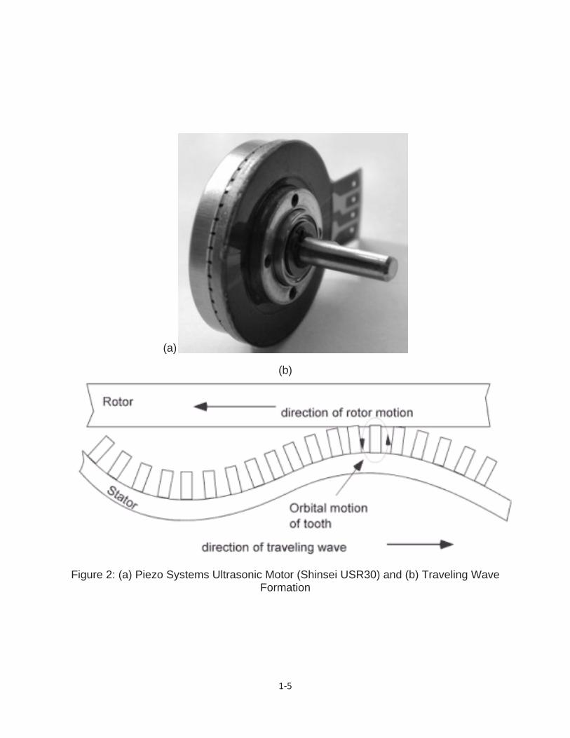
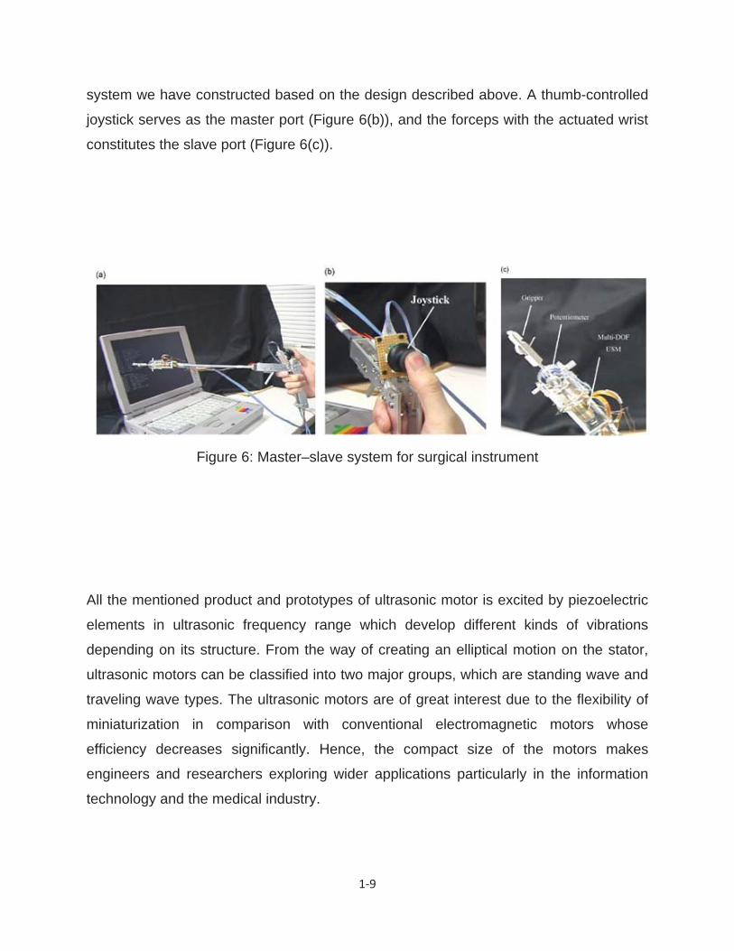
motion enables suturing and knotting procedures. Figure 6(a) shows a master–slave
1 9
system we have constructed based on the design described above. A thumb-controlled
joystick serves as the master port (Figure 6(b)), and the forceps with the actuated wrist
constitutes the slave port (Figure 6(c)).
Figure 6: Master–slave system for surgical instrument
All the mentioned product and prototypes of ultrasonic motor is excited by piezoelectric
elements in ultrasonic frequency range which develop different kinds of vibrations
depending on its structure. From the way of creating an elliptical motion on the stator,
ultrasonic motors can be classified into two major groups, which are standing wave and
traveling wave types. The ultrasonic motors are of great interest due to the flexibility of
miniaturization in comparison with conventional electromagnetic motors whose
efficiency decreases significantly. Hence, the compact size of the motors makes
engineers and researchers exploring wider applications particularly in the information
technology and the medical industry.

1 10
1.3. Scope and contribution
Previous studies have focused on the piezoelectric stator. The stator is induced by
travelling wave or combining two bending modes and a longitudinal mode of the
actuators. The effects on the actuator’s driving frequencies and mounting location on
the stator have been thoroughly examined, however, there is very little literature
concentrating on the structure response and motion behavior of the stator under
different excitation of natural frequencies.
Hence, the objective of this thesis is to classify and characterize the response of the
novel cyclic symmetric stator design in varied natural frequencies using experimental
and analytical techniques. Once the frequency and mode structure are established, the
behavior of the protrusion fingers on the designed stator can be examined. The
contributions of the thesis are:
A cyclic symmetric stator model was developed
The natural frequency and mode shape structure was identified
The structure response of the cyclic symmetric stator and protrusion finger was
examined
The displacement strength and in-plane bending distorted angle of the protrusion
fingers in different rotor contact area was also examined
1.4. Thesis Outline
This thesis presents structure response under different natural frequencies in the novel
cyclic symmetric stator design. A brief overview of this study will be provided in this
section.
The fundamentals of piezoelectricity theory will be briefly discussed in Chapter 2
followed by the configuration of the experimental piezoelectric actuator.

1 11
In chapter 3, commercial software SolidWorks is used to design the structure of the
piezoelectric rotary motor with proposed cyclic symmetric stator. The finite element
method is employed to examine and characterize frequencies and mode shapes of the
stator structure. Deformation of protrusion fingers and disk of the stator are examined
on different natural frequencies and mode shapes.
In chapter 4, the measured data from simulation results is employed to investigate the
displacement strength variation and deformation direction of the protrusion fingertips
through Fourier expansion methods.
Chapter 5 discusses the experimental setup and the result of the novel piezoelectric
rotary motor with cyclic symmetric stator.
Chapter 6 lists the conclusions based on the results obtained from this study. The study
limitations, recommendations and future application directions are also included.
2 1
Chapter 2
Fundamental of piezoelectricity theory
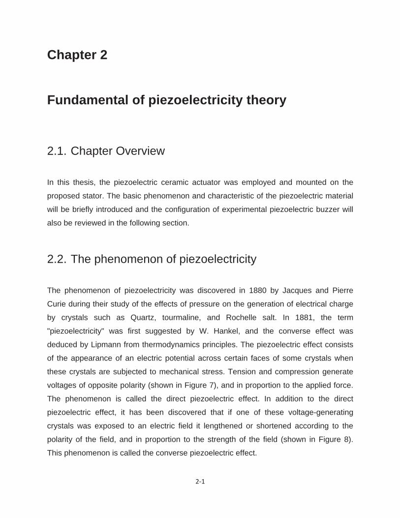
2.1. Chapter Overview
In this thesis, the piezoelectric ceramic actuator was employed and mounted on the
proposed stator. The basic phenomenon and characteristic of the piezoelectric material
will be briefly introduced and the configuration of experimental piezoelectric buzzer will
also be reviewed in the following section.
2.2. The phenomenon of piezoelectricity
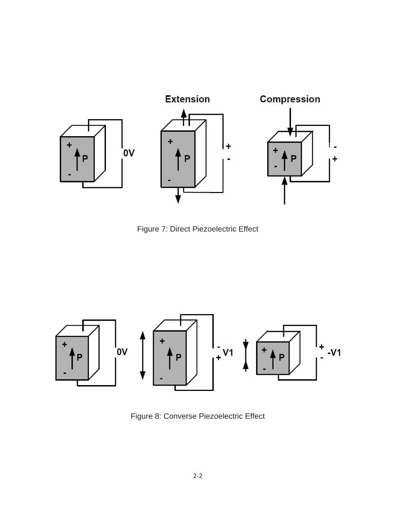
The phenomenon of piezoelectricity was discovered in 1880 by Jacques and Pierre
Curie during their study of the effects of pressure on the generation of electrical charge
by crystals such as Quartz, tourmaline, and Rochelle salt. In 1881, the term
"piezoelectricity" was first suggested by W. Hankel, and the converse effect was
deduced by Lipmann from thermodynamics principles. The piezoelectric effect consists
of the appearance of an electric potential across certain faces of some crystals when
these crystals are subjected to mechanical stress. Tension and compression generate
voltages of opposite polarity (shown in Figure 7), and in proportion to the applied force.
The phenomenon is called the direct piezoelectric effect. In addition to the direct
piezoelectric effect, it has been discovered that if one of these voltage-generating
crystals was exposed to an electric field it lengthened or shortened according to the
polarity of the field, and in proportion to the strength of the field (shown in Figure 8).
This phenomenon is called the converse piezoelectric effect.
2 2
Figure 7: Direct Piezoelectric Effect
Figure 8: Converse Piezoelectric Effect

2 3
2.3. Piezoelectric Materials
The phenomenon of piezoelectricity appears in natural and synthetic crystals such as
quartz, Rochelle salt, lithium sulphate; and ammonium dihydrogen phosphate, as well
as in piezoceramic materials such as lead zirconate titanate (PZT), barium titanate, and
cadmium sulphide. These materials usually have a perovskite structure such as the one
shown in Figure 9 for a piezo-ceramic material. The perovskite structure exists in two
crystallographic forms. Above the Curie temperature, the perovskite presents a cubic
structure (shown in Figure 9a) and below the Curie temperature they transform into a
tetragonal structure (shown in Figure 9b).
Figure 9: Perovskite structure
In the tetragonal state, each unit cell has an electric dipole, for example, there is a small
charge differential between each end of the unit cell. A mechanical deformation (such
as a compressive force) can decrease the separation between the cations and anions
which produces an internal field or voltage. Also, if an electric field is applied along the

2 4
electric dipole, the tetragonal structure will deform due to the attraction or rejection
forces between charges of the same or different polarities. The natural and synthetic
crystals contain a monocrystalline structure which has the polarization orientated in the
same direction as shown in Figure 10.
Figure 10: Polarization of crystals
In order to be of practical use, these crystals can only be cut in simple shapes, such as
rectangular plates along the crystallographic axes. Moreover, certain synthetic
piezoelectric materials called piezoceramic materials are used in order to obtain various
geometries such as rings, tubes or disks. These materials are powders, which enable
themselves to be sintered in any shape and be more useful for practical applications. In
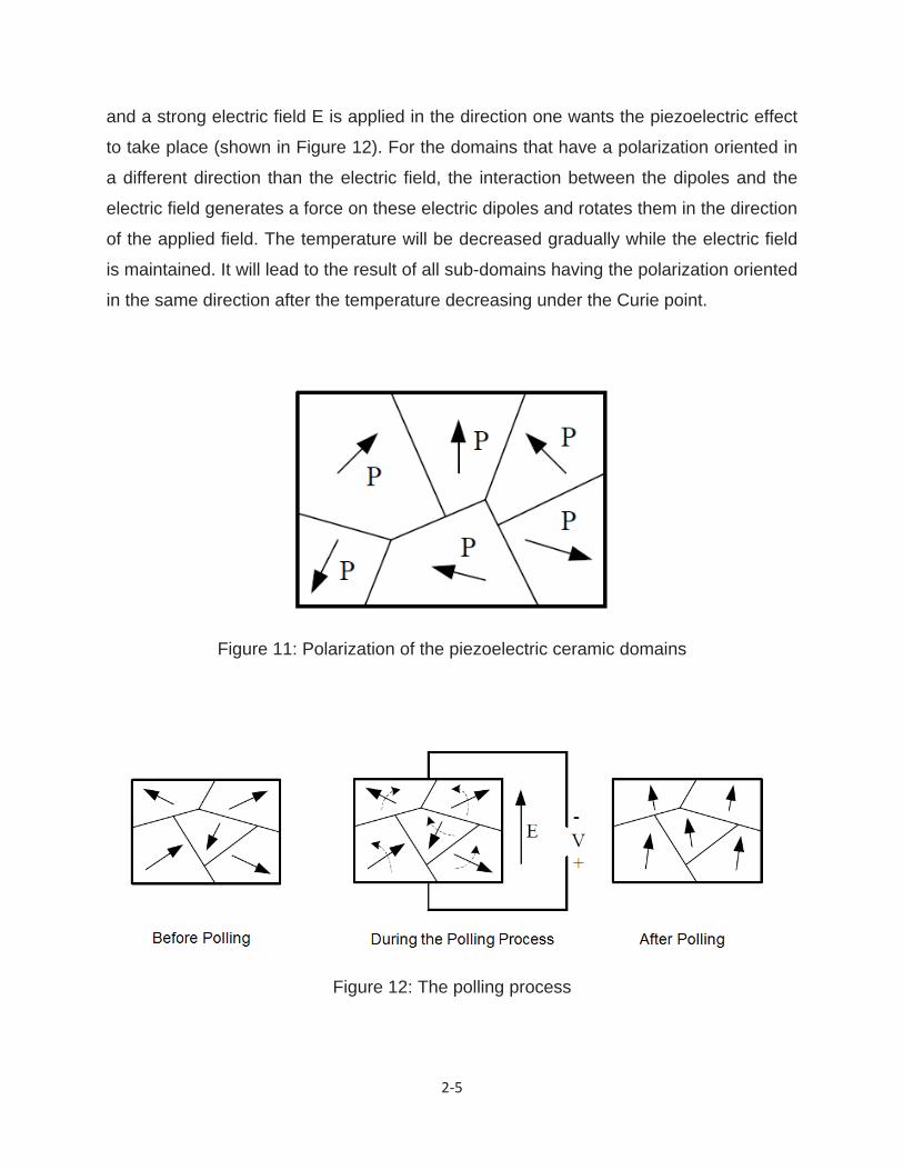
contrast with the crystals, some disadvantages exists that after they are sintered, the
internal domains of polycrystalline structure have the polarizations randomly oriented as
shown in Figure 11, and the global result of the piezoelectric effect is zero. To be able to
use them as piezoelectric materials, one has to proceed to the re-orientation of the
domains into one direction. This is usually done by a procedure called polling. During
this procedure, the piezoelectric object is heated at a temperature above the Curie point
2 5
and a strong electric field E is applied in the direction one wants the piezoelectric effect
to take place (shown in Figure 12). For the domains that have a polarization oriented in
a different direction than the electric field, the interaction between the dipoles and the
electric field generates a force on these electric dipoles and rotates them in the direction
of the applied field. The temperature will be decreased gradually while the electric field
is maintained. It will lead to the result of all sub-domains having the polarization oriented
in the same direction after the temperature decreasing under the Curie point.
Figure 11: Polarization of the piezoelectric ceramic domains
Figure 12: The polling process
2 6
2.4. Piezoelectric Actuator
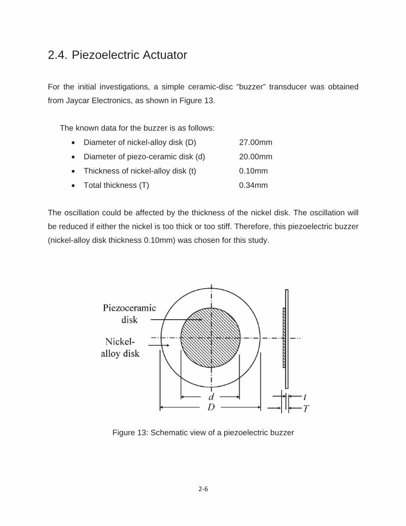
For the initial investigations, a simple ceramic-disc “buzzer” transducer was obtained
from Jaycar Electronics, as shown in Figure 13.
The known data for the buzzer is as follows:
Diameter of nickel-alloy disk (D) 27.00mm
Diameter of piezo-ceramic disk (d) 20.00mm
Thickness of nickel-alloy disk (t) 0.10mm
Total thickness (T) 0.34mm
The oscillation could be affected by the thickness of the nickel disk. The oscillation will
be reduced if either the nickel is too thick or too stiff. Therefore, this piezoelectric buzzer
(nickel-alloy disk thickness 0.10mm) was chosen for this study.
Figure 13: Schematic view of a piezoelectric buzzer

3 1
Chapter 3
System Configuration
3.1. Chapter Overview
A structure of the piezoelectric rotary motor with novel cyclic symmetric stator will be
introduced and also the geometry parameter and material properties will be specified in
this chapter. Furthermore, the novel cyclic symmetric stator structure carried with
identical and evenly-spaced protrusion will be examined through finite element
simulations. Particularly, the emphasis is placed on the behavior of the disk and fingers
of the stator when different excitation frequencies and mode shapes are introduced into
the structure. The fingers movement change in frequencies was observed while
investigating the mode shapes.
3.2. Model Description
The objective of this thesis is to develop a novel cyclic symmetric stator which is driven
by piezoelectric ceramic buzzers. Previous studies focus on combining two bending
modes and a longitudinal mode of the actuators which employed dual-phase-driven
ultrasonic actuators [13]-[16]. Those designs were still in large size and lack in output
forces per volumes due to the driving principles, and the dual-phase-driven ultrasonic
actuators. A dual-phase-driven ultrasonic actuator is believed to be a better fit for multi-
degree-of-freedom mechanisms, however, it requires more time and cost to
manufacture and is hard to miniaturize because their frequencies must correspond to
each other. On the contrary, the single-phase-driven ultrasonic actuator can be made

3 2
with lower cost and is also easy to miniaturize. Hence, a novel cyclic symmetric stator
design for applying the plural single-phase-driven actuators is developed for this thesis.
Figure 14: Structure of the piezoelectric rotary motor
Piezoelectricceramicactuator
Sphericalrotor
Stator
Base
screw

3 3
In the beginning, the structure of proposed piezoelectric motor as illustrated in Figure 14
was built by using commercial finite element package (SolidWorks). As depicted in the
plot, the model consists of four basic parts: the spherical rotor, the stator, the
piezoelectric ceramic buzzer mounted on the stator and the base. Then, the design of
mechanical components is required to be manufactured.
3.2.1. Rotor
The rotor is a hollow spherical-shape ball of size diameter 40mm. For the experimental
observations, a ping-pong ball was used as an alternative for metal rotor due to
technical difficulty of manufacturing a metal spherical-shape ball.
3.2.2. Stator
The proposed stator consists of disk and protrusion fingers, which was made of ABS
material. The stator disk (Figure 15) with inside radius =3.2mm, outside radius
=49mm and the thickness of the disk h=3mm was physically clamped around with
base by a bolt screw. There are eight evenly-spaced protrusion fingers on the surface of
the stator disk. The arch-shape tip was designed on each of the protrusion fingers,
which holds and drives the spherical-rotor. The rotor in contact with the surface point of
the fingertips was driven by frictional force. For the purpose of saving manufacturing
time and reducing cost of the material, the rapid prototype technology was employed to
manufacture the cyclic symmetric stator.

3 4
Figure 15: schematic of the cyclic symmetric stator
3 5
3.2.3. Piezoelectric ceramic buzzer
The piezoelectric ceramic buzzer consist of nickel-alloy disk with diameter 27mm and
piezo-ceramic disk with diameter 20mm, which was attached to the surface underneath
the cyclic symmetric stator. In order to gain optimal actuation result, it is essential to
have strong bonding between the stator and the piezoelectric ceramic. Thus, in order to
achieve this, epoxy adhesive was applied at each interface. This piezoelectric ceramic
buzzer was driven by the sinusoidal wave which is generated by the function generator
and is enhanced by the power amplifier circuit.
3.2.4. Base
The base is a moveable substrate with size of , which is used to clamp
the cyclic symmetric stator.
3.3. Finite Element Analysis
A finite element analysis is very important for designing a novel piezoelectric rotary
motor with cyclic symmetric stator because it offers information about possible driving
frequency and rotational direction of the motor. In order to examine the displacement
and structure response on the stator disk and protrusion fingers:
Proposed cyclic symmetric stator solid model was created
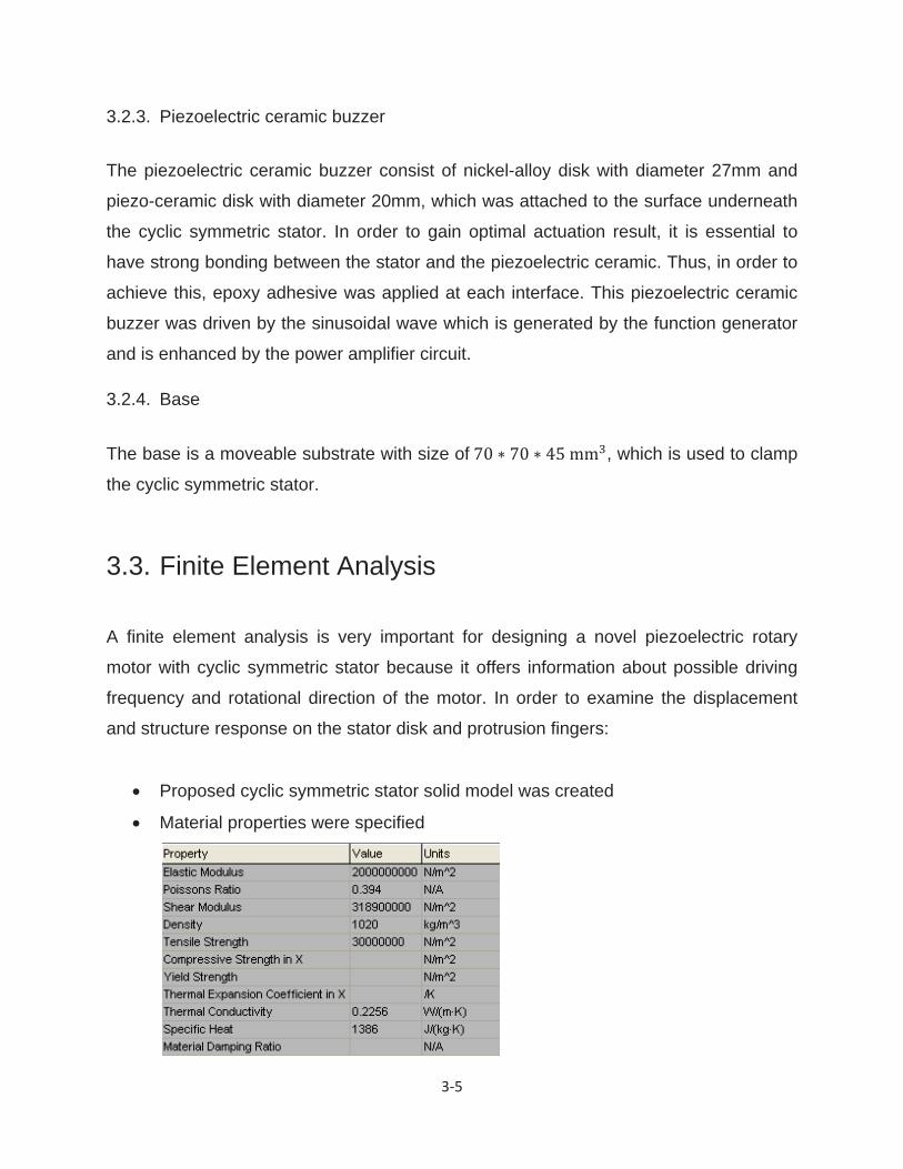
Material properties were specified
3 6
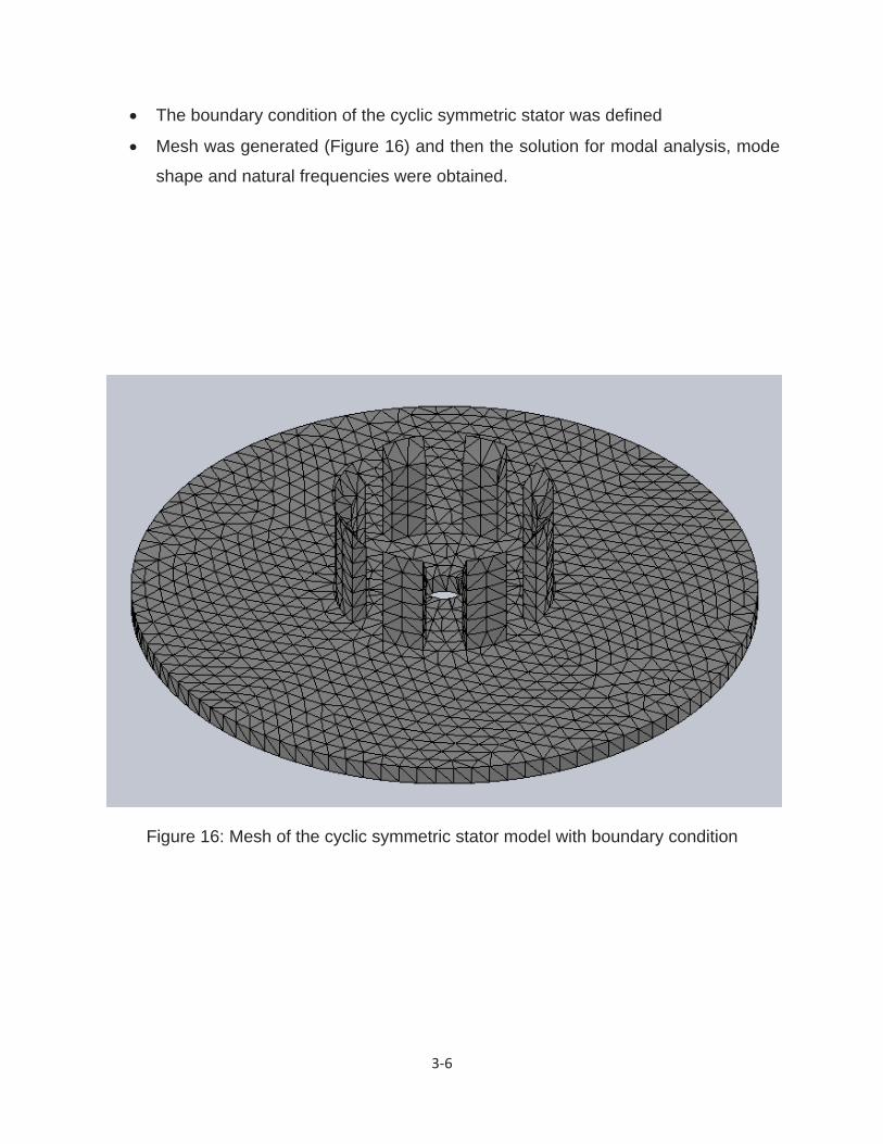
The boundary condition of the cyclic symmetric stator was defined
Mesh was generated (Figure 16) and then the solution for modal analysis, mode
shape and natural frequencies were obtained.
Figure 16: Mesh of the cyclic symmetric stator model with boundary condition
3 7
Following the nomenclature and mode structure characterized in reference [17]-[18],
letter is given to distinguish the cyclic symmetric stator’s vibration modes from those
modes denoted as (m, n) in axis-symmetric case, where m represents number of nodal
circles and n is the number nodal diameters, respectively. For instance, P(0, 1) stands
for the cyclic symmetric stator’s vibration mode having zero nodal circle and one nodal
diameter in axis-symmetric disk case.
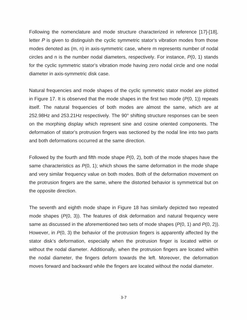
Natural frequencies and mode shapes of the cyclic symmetric stator model are plotted
in Figure 17. It is observed that the mode shapes in the first two mode (P(0, 1)) repeats
itself. The natural frequencies of both modes are almost the same, which are at
252.98Hz and 253.21Hz respectively. The 90° shifting structure responses can be seen
on the morphing display which represent sine and cosine oriented components. The
deformation of stator’s protrusion fingers was sectioned by the nodal line into two parts
and both deformations occurred at the same direction.
Followed by the fourth and fifth mode shape P(0, 2), both of the mode shapes have the
same characteristics as P(0, 1); which shows the same deformation in the mode shape
and very similar frequency value on both modes. Both of the deformation movement on
the protrusion fingers are the same, where the distorted behavior is symmetrical but on
the opposite direction.
The seventh and eighth mode shape in Figure 18 has similarly depicted two repeated
mode shapes (P(0, 3)). The features of disk deformation and natural frequency were
same as discussed in the aforementioned two sets of mode shapes (P(0, 1) and P(0, 2)).
However, in P(0, 3) the behavior of the protrusion fingers is apparently affected by the
stator disk’s deformation, especially when the protrusion finger is located within or
without the nodal diameter. Additionally, when the protrusion fingers are located within
the nodal diameter, the fingers deform towards the left. Moreover, the deformation
moves forward and backward while the fingers are located without the nodal diameter.
3 8
Figure 17: Simulation result from Solidworks (Mode Shape 1~5)

3 9
Figure 18: Simulation result from Solidworks (Mode Shape 6~10)
3 10
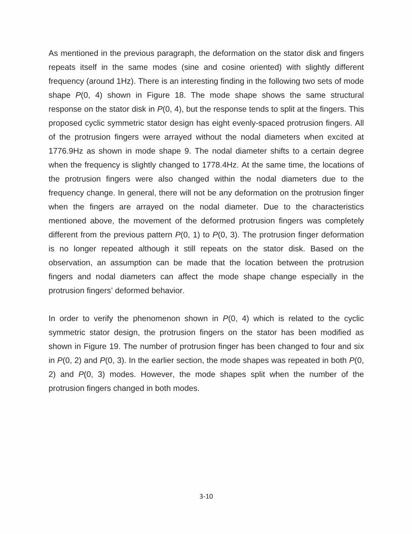
As mentioned in the previous paragraph, the deformation on the stator disk and fingers
repeats itself in the same modes (sine and cosine oriented) with slightly different
frequency (around 1Hz). There is an interesting finding in the following two sets of mode
shape P(0, 4) shown in Figure 18. The mode shape shows the same structural
response on the stator disk in P(0, 4), but the response tends to split at the fingers. This
proposed cyclic symmetric stator design has eight evenly-spaced protrusion fingers. All
of the protrusion fingers were arrayed without the nodal diameters when excited at
1776.9Hz as shown in mode shape 9. The nodal diameter shifts to a certain degree
when the frequency is slightly changed to 1778.4Hz. At the same time, the locations of
the protrusion fingers were also changed within the nodal diameters due to the
frequency change. In general, there will not be any deformation on the protrusion finger
when the fingers are arrayed on the nodal diameter. Due to the characteristics
mentioned above, the movement of the deformed protrusion fingers was completely
different from the previous pattern P(0, 1) to P(0, 3). The protrusion finger deformation
is no longer repeated although it still repeats on the stator disk. Based on the
observation, an assumption can be made that the location between the protrusion
fingers and nodal diameters can affect the mode shape change especially in the
protrusion fingers’ deformed behavior.
In order to verify the phenomenon shown in P(0, 4) which is related to the cyclic
symmetric stator design, the protrusion fingers on the stator has been modified as
shown in Figure 19. The number of protrusion finger has been changed to four and six
in P(0, 2) and P(0, 3). In the earlier section, the mode shapes was repeated in both P(0,
2) and P(0, 3) modes. However, the mode shapes split when the number of the
protrusion fingers changed in both modes.

3 11
Figure 19: Modified cyclic symmetric stator with 4 and 6 evenly-spaced protrusion fingers in P(0,2) and P(0,3) respectively

3 12
In this FEM simulation, it was observed that the proposed stator is an axis-symmetric
disk structure. The vibration modes of the stator are classified as being either doublet
(in which case two linearly independent sine and cosine-oriented vibration modes of
common frequency exist) or as singlet (where the frequency is an isolated root of a
characteristic equation, and the vibration mode itself is axis-symmetrical). Those two
classes of modes are further categorized according to the numbers m and n of nodal
circles and diameters respectively [17]. It is found that the deformation relations
between stator protrusion fingers and nodal diameters are significantly associated.
Although the distortion of the stator disk behaves the same, different number of
protrusion finger design can alter the fingers’ movement directions under certain
excitation.
3.4. Chapter summary
This chapter has presented a novel design of the piezoelectric rotary motor with cyclic
symmetric stator. The schematic of the piezoelectric rotary motor was discussed and
each part of the motor was introduced. The natural frequencies and structure responses
of the cyclic symmetric stator were examined by using finite element approach. The
focus was placed on the structure response between stator disk and protrusion fingers.
Moreover, the movement of the stator disk and protrusion finger in different mode
shapes has been observed. Based on the observation results, the mode shape of cyclic
symmetric stator split and repeated in different frequencies. With the proposed cyclic
symmetric stator design, the mode shape repeated in P(0, 1), P(0, 2) and P(0, 3) but
split in P(0, 4).
In this mode shape (P(0, 4)), the mode shape displayed the same distortion on the
stator disk in both sine and cosine oriented components. However, completely different
distorted directions were found on the protrusion fingers. This interesting phenomenon
can also be duplicated in those repeated modes (P(0, 2) and P(0, 3)) when the number
of protrusion fingers is changed to match the nodal diameters. According to the

3 13
modification on stator design, the number of the protrusion fingers exposed significant
association with the nodal diameters. As a result, this feature can be employed to
determine driving direction in the future experiment.

4 1
Chapter 4
Parametric study of the cyclic symmetric stator
4.1. Chapter Overview
The structure response of the cyclic symmetric stator disk and protrusion fingers was
investigated in the previous chapter. The split mode patterns have been found on the
protrusion finger in P(0,4). Due to the novel phenomenon found in Chapter 3, the
deformation movement performance of the protrusion fingertips in both split structure
responses in P(0,4) will be further investigated by parametric studies in this chapter.
The parametric studies of displacement strength variation and in-plane bending
deformation angle of the protrusion fingertips will be examined. The data that obtained
from finite element simulation result will be used to evaluate through Fourier coefficients
of sine and cosine oriented components.
4.2. Parametric study
According to the simulation results made in the previous chapter, the displacement
strength at outer disk edge indicated higher value than at inner edge as shown in Figure
17 and Figure 18. However, it is hard to find the deformation perform on the protrusion
fingers from those figures. In order to obtain optimal performance of the protrusion
finger movement of the stator, the different contact angle between stator and rotor will
be used as variables in the parametric studies. The two parameters, displacement
strength and in-plane bending angle of the fingers, will be examined in this section.
4 2
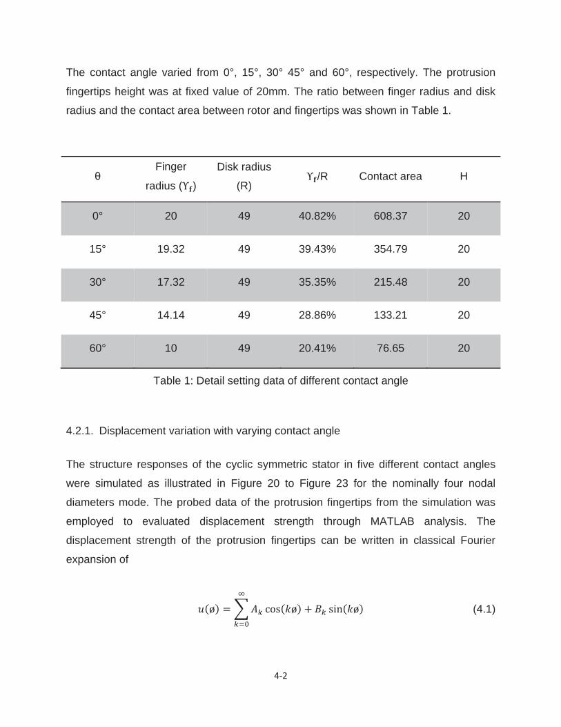
The contact angle varied from 0°, 15°, 30° 45° and 60°, respectively. The protrusion
fingertips height was at fixed value of 20mm. The ratio between finger radius and disk
radius and the contact area between rotor and fingertips was shown in Table 1.
Table 1: Detail setting data of different contact angle
4.2.1. Displacement variation with varying contact angle
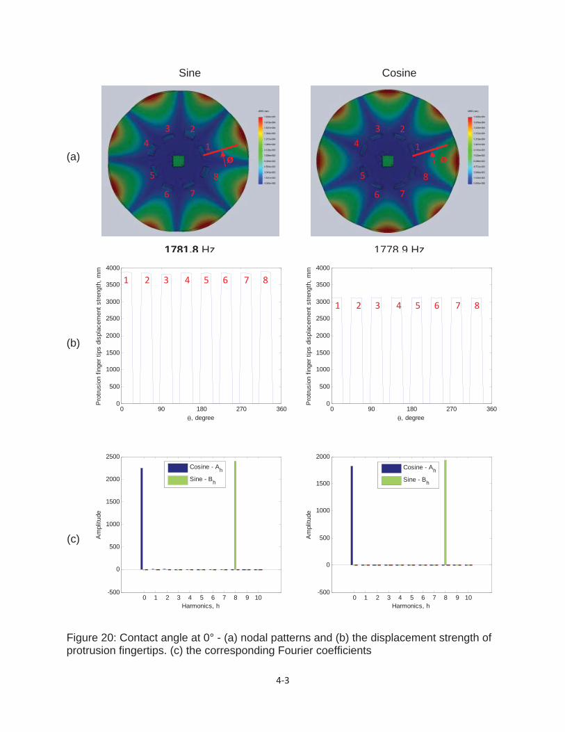
The structure responses of the cyclic symmetric stator in five different contact angles
were simulated as illustrated in Figure 20 to Figure 23 for the nominally four nodal
diameters mode. The probed data of the protrusion fingertips from the simulation was
employed to evaluated displacement strength through MATLAB analysis. The
displacement strength of the protrusion fingertips can be written in classical Fourier
expansion of
(4.1)
Finger
radius ( )
Disk radius
(R) /R Contact area H
0° 20 49 40.82% 608.37 20
15° 19.32 49 39.43% 354.79 20
30° 17.32 49 35.35% 215.48 20
45° 14.14 49 28.86% 133.21 20
60° 10 49 20.41% 76.65 20
4 3
(a)
Sine
1781.8 Hz
Cosine
1778.9 Hz
(b)
(c)
Figure 20: Contact angle at 0° - (a) nodal patterns and (b) the displacement strength of protrusion fingertips. (c) the corresponding Fourier coefficients
0 90 180 270 3600
500
1000
1500
2000
2500
3000
3500
4000
, degree
Pro
trusi
on fi
nger
tips
dis
plac
emen
t stre
ngth
, mm
0 90 180 270 3600
500
1000
1500
2000
2500
3000
3500
4000
, degree
Pro
trusi
on fi
nger
tips
dis
plac
emen
t stre
ngth
, mm
0 1 2 3 4 5 6 7 8 9 10-500
0
500
1000
1500
2000
2500
Harmonics, h
Am
plitu
de
0 1 2 3 4 5 6 7 8 9 10-500
0
500
1000
1500
2000
Harmonics, h
Am
plitu
de
Cosine - Ah
Sine - Bh
Cosine - Ah
Sine - Bh
1
23
4
5
6 7
8
ø ø1
23
4
5
6 7
8
1 2 3 4 5 6 7 8
1 2 3 4 5 6 7 8

4 4
(a)
Sine
1776.9 Hz
Cosine
1778.4 Hz
(b)
(c)
Figure 21: Contact angle at 30° - (a) nodal patterns and (b) the displacement strength of protrusion fingertips. (c) the corresponding Fourier coefficients
0 90 180 270 3600
1000
2000
3000
4000
5000
6000
, degree
Pro
trusi
on fi
nger
tips
dis
plac
emen
t stre
ngth
, mm
0 90 180 270 3600
1000
2000
3000
4000
5000
6000
, degree
Pro
trusi
on fi
nger
tips
dis
plac
emen
t stre
ngth
, mm
0 1 2 3 4 5 6 7 8 9 10-1000
-500
0
500
1000
1500
2000
2500
Harmonics, h
Am
plitu
de
0 1 2 3 4 5 6 7 8 9 10-200
0
200
400
600
800
1000
1200
1400
1600
Harmonics, h
Am
plitu
de
Cosine - Ah
Sine - Bh
Cosine - Ah
Sine - Bh
4 5
(a)
Sine
1777.2 Hz
Cosine
1778.3 Hz
(b)
(c)
Figure 22: Contact angle at 45° - (a) nodal patterns and (b) the displacement strength of protrusion fingertips. (c) the corresponding Fourier coefficients
0 90 180 270 3600
1000
2000
3000
4000
5000
6000
, degree
Pro
trusi
on fi
nger
tips
dis
plac
emen
t stre
ngth
, mm
0 90 180 270 3600
1000
2000
3000
4000
5000
6000
, degree
Pro
trusi
on fi
nger
tips
dis
plac
emen
t stre
ngth
, mm
0 1 2 3 4 5 6 7 8 9 10-500
0
500
1000
1500
2000
2500
3000
Harmonics, h
Am
plitu
de
0 1 2 3 4 5 6 7 8 9 10-200
0
200
400
600
800
1000
Harmonics, h
Am
plitu
de
Cosine - Ah
Sine - Bh
Cosine - Ah
Sine - Bh
4 6
(a)
Sine Cosine
1779.1 Hz
(b)
(c)
Figure 23: Contact angle at 60° - (a) nodal patterns and (b) the displacement strength of protrusion fingertips. (c) the corresponding Fourier coefficients
0 90 180 270 3600
1000
2000
3000
4000
5000
6000
, degree
Pro
trusi
on fi
nger
tips
dis
plac
emen
t stre
ngth
, mm
0 90 180 270 3600
1000
2000
3000
4000
5000
6000
, degree
Pro
trusi
on fi
nger
tips
dis
plac
emen
t stre
ngth
, mm
0 1 2 3 4 5 6 7 8 9 10-800
-600
-400
-200
0
200
400
600
800
1000
Harmonics, h
Am
plitu
de
0 1 2 3 4 5 6 7 8 9 10-500
0
500
1000
Harmonics, h
Am
plitu
de
Cosine - Ah
Sine - Bh
Cosine - Ah
Sine - Bh
4 7
In order to represent the distorted appearance for the mode around the protrusion
fingertips where is the circumferential measure starting from first protrusion fingertip.
The nodal patterns, displacement strength and Fourier amplitude of the structure
response of the split modes at contact angle 0° depicted in Figure 20. The Fourier
amplitude was plotted up to k=10 harmonic count in Figure 20(c). The eight peak
displacement strength value represented each of the fingertips (starting from shown in
Figure 20(a)). The displacement strengths in Figure 20(b) were around 3800mm and
3150mm in sine and cosine oriented components respectively. Each of the fingertips
revealed almost the same displacement strength in both sine and cosine modes.
However, it was noted that a slight difference in displacement strength was displayed on
each of the fingertips. These interesting characteristic can be further investigated in the
future study. In comparison with contact angle 0°, a higher displacement strength value
was shown at contact angle 15°, however other features were almost the same as at 0°.
In the earlier section, the higher displacement strength was found at the disk’s outer
edge compared to its inner edge. Contrastingly, higher displacement strength on
protrusion fingertips was revealed at contact angle 15° (approximately 5000mm)
compared to 0 (approximately 4000mm).
At contact angle 30°, the displacement strength of each protrusion fingertips
significantly changed (shown in Figure 21). The displacement strength of each fingers
were no longer of the same value; the highest strength value was revealed by the 4th
and 8th finger ( 5000mm), followed by 1st and 5th finger ( 4700mm). The rest of the
fingers’ strength were only at 2000mm. Based on this observation, it is noted that these
four fingers (1st, 4th, 5th and 8th) located symmetrically dominated the main role of rotor
driving. As a result, the rotor movement was moving in a diagonal direction.
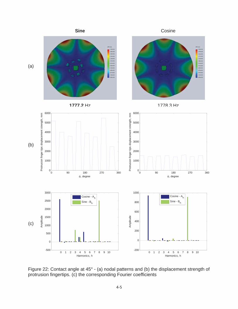
Similarly, at contact angle 45° (Figure 22) a significant difference was also exhibited on
protrusion fingertips and the displacement strength appeared the same trend as those
fingers at 30° contact angle; dominant fingertips appeared selectively. However, the
dominant fingertips in 45° differ from that of 30°; dominant fingertips were not as
prevailing and not located symmetrically, resulting in an erratic vertical motion. In the

4 8
last contact angle (60°), it is observed that the structure response is totally different from
the previous angles as the finger radius is too narrow (10mm) to match the nodal
diameters (Figure 23). Additionally, nodal pattern no longer repeated. It is noted that
these split mode response will no longer be duplicated when the finger radius is too
narrow (10mm). Hence, simulation beyond 45° is out of question to achieve optimal
displacement in split modes.
4.2.2. In-plane deformation angle with varying contact angle
In the last section, displacement strength variation of each protrusion finger was found
at different contact angle. It can also effect on the direction of the rotor. In this section,
the in-plane bending deformation angle of each fingertip will be investigated. The
bending deformation angle ( ) with respect to x and z direction of the fingertips
displacement as
(4.2)
was calculated to evaluate the fingertip movement change. Figure 24 illustrates a 90-
degree phase difference between sine and cosine mode same as that shown in nodal
pattern of contact angle 0°. The bending deformation angle decline on each fingertip in
cosine oriented component; bending motion angle still remains the same in sine mode.
It is noted that the decline angle can affect the twisting result of the rotor. At contact
angle 15°, the same bending deformation pattern arose as at 0°. Hence, based on the
observed result, the rotational variation is more likely to alter by introducing the cosine
oriented component in these two angles.
The significant change was found between sine and cosine modes at contact angle 30°
shown in Figure 25; the bending deformation pattern was no longer at 90-degree shift
from sine to cosine mode. On the one hand, the bending deformation angle in sine
mode depicted a sunken bow shape at the fingertips, which means the fingertips

4 9
distorted at the center rather than a decline deformation at one side in cosine mode.
The sunken bow shape fingertips results in a movement at a fixed angle, rather than
moving at a diagonal angle with the decline deformation’s angle. On the other hand, the
high bending deformation angle ( revealed in four fingertips (1st, 4th, 5th and 8th).
As finger 1 and 8 is at a negative bending deformation angle, while finger 4 and 5 is at a
positive angle, this result in a clockwise rotational motion.
At contact angle 45°, the bending deformation pattern switched back to the same as 0°
and 15°. It also indicated the decline bending deformation angle on the protrusion
fingertips in cosine mode. Moreover, the bending deformation angle revealed
inconsistency in both sine and cosine mode at contact angle 60° as shown in Figure 26.
Due to the finger radius is too narrow, the bending angle affected each other. It is hard
to find any patterns and relations in both sine and cosine mode.

4 10
(a)
(b)
Figure 24: Contact angle at 0° - Protrusion fingertips deformed angle in (a) sine and (b) cosine oriented components
0 90 180 270 360-80
-60
-40
-20
0
20
40
60
80
, degree
in-p
lane
ben
ding
def
orm
atio
n an
gle,
deg
ree
0 90 180 270 360-80
-60
-40
-20
0
20
40
60
80
, degree
in-p
lane
ben
ding
def
orm
atio
n an
gle,
deg
ree

4 11
(a)
(b)
Figure 25: Contact angle at 30° - Protrusion fingertips deformed angle in (a) sine and (b) cosine oriented components
0 90 180 270 360-100
-80
-60
-40
-20
0
20
40
60
80
100
, degree
in-p
lane
ben
ding
def
orm
atio
n an
gle,
deg
ree
0 90 180 270 360-80
-60
-40
-20
0
20
40
60
80
100
, degree
in-p
lane
ben
ding
def
orm
atio
n an
gle,
deg
ree
4 12
(a)
(b)
Figure 26: Contact angle at 60° - Protrusion fingertips deformed angle in (a) sine and (b) cosine oriented components
0 90 180 270 360-80
-60
-40
-20
0
20
40
60
80
, degree
in-p
lane
ben
ding
def
orm
atio
n an
gle,
deg
ree
0 90 180 270 360-50
0
50
100
, degree
in-p
lane
ben
ding
def
orm
atio
n an
gle,
deg
ree
4 13
4.3. Chapter summary
Parametric studies for displacement variation and in-plane bending deformation with
varying contract angle between stator and rotor have been conducted for identification
of movement performance of the protrusion fingertips. The variation of displacement
strength value was found in each protrusion fingertips in different contact angle. Certain
fingertips were found having high displacement strength value and dominated the
bending motion in both contact angle at 30° and 45°. Especially, at contact angle 30°,
four fingers (1st, 4th, 5th and 8th) located symmetrically dominated the main role of rotor
driving in a diagonal direction. The same bending deformation angle patterns were
discover in both sine and cosine modes at contact angle 0°, 15° and 45°. On the
contrary, a high bending deformation angle ( revealed in four fingertips (1st, 4th, 5th
and 8th) at 30° contact angle, this result in a clockwise rotational motion. The nodal
pattern was no longer repeated at contact angle 60°, meanwhile, the displacement
strength value revealed much smaller than the other contact angles. In addition, It is
hard to find any patterns and relations in both sine and cosine mode due to the bending
angle was affected by each fingers.
5 1
Chapter 5
Experimental Result
For experimental testing, the proposed piezoelectric rotary motor with cyclic symmetric
stator will be presented in this chapter. The detail experimental setup will be discussed
in the following section. The piezoelectric buzzer is attached to the cyclic symmetric
stator prototype for driving the stator’s natural frequencies and also the piezoelectric
buzzer mounting location will be reviewed by using the Chlandi figures. This
experimental prototype is built to examine the consistency with the aforementioned
simulation result.
5.1. Experimental setup
For rotation experimental testing, the diagram of the experimental platform is show in
Figure 27 and is comprised of the following components:
the piezoelectric rotary motor model
the function generator – use to provide a voltage with variable frequency, which
is used to drive the power amplifier circuit
the power amplifier circuit - amplify the voltage received from the function
generator and the amplified voltage is applied to the piezoelectric ceramic
buzzers
the oscilloscope - use to monitor the voltage supplied to the piezoelectric ceramic
buzzers

5 2
Figure 27: Piezoelectric rotary motor experimental setup
5 3
5.2. Experimental result
In Chapter 3 of this thesis, the cyclic symmetric stator was modeled using commercial
finite element package. By using this software, the natural frequencies and mode
shapes have been simulated. In order to validate the optimal movement performance of
protrusion finger in terms of the fingers location on the stator, two parametric studies
with varying contact angle have been conducted with Fourier analysis by using
MATLAB. As a result, the significant changes of displacement strength and in-plane
bending deformation angle of the protrusion fingertips were found at contact angle 30°.
Hence, the piezoelectric rotary motor with cyclic symmetric stator was built for this
experiment (Figure 27). The protrusion fingertips with contact angle 30° was employed
in this experiment model.
The moveable base was clamped on the table with C-clamps. The stator was axis-
symmetric clamped at inner radius with base by a bolt screw. In order to conduct the
optimal piezoelectric ceramic buzzers mounting positions and make sure the correct
structure response is obtained, the colored sand was used to visualize the Chlandi
figure as shown in Figure 28. As a result, the piezoelectric ceramic buzzers are
accurately placed on the positions beneath cyclic symmetric stator. The resonance
frequencies were found at 1776Hz and 1778Hz in the simulation respectively. However,
the experimental resonance frequencies were obtained at around 1711Hz and 1715Hz
respectively. The experimental resonance frequencies are slightly different from the
simulated one. It might due to the material properties and geometric parameters setting
deviations. With this experimental setup, the rotation speed and direction of the
spherical rotor was examined. The result shows that the rotation speed was obtained at
3.52 rpm in clockwise with diagonal angle as shown in Figure 29 when the piezoelectric
ceramic buzzers were driven at 20 Vp-p with the sinusoidal wave at 1711Hz. Another
result indicates that the spherical rotor remained still when the piezoelectric ceramic
buzzers were driven at 1715Hz. In this experiment, the preload is applied by weight of
the spherical ball rotor (2.7 grams).

5 4
Figure 28: Chlandi-type measurement used on the cyclic symmetric stator

5 5
Figure 29: Rotation performance

5 6
5.3. Chapter summary
The piezoelectric rotary motor with cyclic symmetric stator driven by piezoelectric
ceramic buzzers has been developed. Based on the simulated results, the optimal
performance can be obtained with stator and rotor contact angle at 30°. Furthermore,
the protrusion fingertips were showing the tendency of driving rotor in clockwise and
diagonal direction. With this experimental setup, rotational results were obtained at
rotating speed of 3.52 rpm clockwise with the diagonal angle. This result shows that the
experimental model and simulated assumption match consistently.

6 1
Chapter 6
Summary
This thesis discusses the cyclic symmetric stator model in (a) relations between number
of the protrusion finger design and structure response under different excitation
frequencies and (b) displacement strength and in-plane bending deformation angle with
varying contact angle. The following sections summarize the contributions of this thesis
and provide directions for future work.
6.1. Structure response in a novel cyclic symmetric stator
model
The novel piezoelectric rotary motor and cyclic symmetric stator structure was built. The
frequencies and structure responses of cyclic symmetric stator with evenly-spaced
protrusion fingers were discussed in Chapter 3 by using finite element simulation. The
distorted motions of the stator disk and protrusion fingers were observed in different
modes. The structure responses of the sine and cosine components of cyclic symmetric
stator were normally repeated in different frequencies. Nevertheless, the particular split
modes were found when the protrusion fingers array matched the nodal diameters. It is
indicated that protrusion fingers’ number significantly associated with the nodal
diameters, which means the deformation behavior of the fingers can be altered by
changing the design of the finger numbers. This novel finding develops a new stator
design concept for piezoelectric or ultrasonic application.

6 2
6.2. Displacement strength and in-plane deformation
angle of the cyclic symmetric stator
The displacement strength variation of the cyclic symmetric stator in different contact
angle is discussed in chapter 4, with the emphasis placed on the strength difference
between each finger. In principle, the bending motion is offset by the symmetric and
opposite fingers as shown in the simulation. However, through observation and Fourier
analysis, different displacement strength on the protrusion fingers was found in the
different contact angle especially in 30°, this result in various rotor rotational directions.
Additionally, the in-plane bending deformation angle of the protrusion fingertips is also
discussed in chapter 4. The focus is placed on the bending angle rather than the
bending amplitude. According to the observation, different bending deformation angle
exhibited on each protrusion fingertips. These slight changes in bending deformation
angle exhibited the tendency of varying rotor rotational direction. Based on these two
reasons, the contact angle between stator and rotor is shown to be a design option to
modify these two parameters of the fingertips for motion direction control.
6.3. Limitations
The thesis-based research contains several limitations due to the shortage of the
resources. The following issues for the novel stator design with evenly-space protrusion
fingers have been identified in this study.
1. Piezoelectric ceramic driving system – In this experimental prototype, the
function generator and power amplifier circuit were employed as the driving
sources. With this setting, the low voltage sinusoidal wave (Vp-p=20V) was
employed instead of using high voltage to drive the piezoelectric actuators, which
is due to the lack of the equipment. In order to fulfill the optimal actuation, plural
buzzers were employed to achieve this purpose. However, it changed the mass

6 3
property and it was likely to affect the structure responses. Moreover, it is unlikely
to obtain the optimal result without optimum actuation output. Hence, it is
recommended that a driving system with high voltage power amplifier should be
developed to drive the actuators.
2. The manufacturing of the stator and rotor – The rapid prototype technology is
used to manufacture the cyclic symmetric stator in order to reduce time and cost
consumption. Instead of manufacturing proper rotor, a ping-pong ball was simply
used as a rotor due to technical difficulty of manufacturing a spherical-shape ball.
There are some deviations exhibiting between the stator and the rotor. As a
result, it is more likely to affect the rotational direction and also reduce the
rotational speed. Therefore, it is recommended that the accurately manufactured
stator and rotor should be replaced in order to solve these problems and ensure
the rotation performance.
6.4. Directions for future work
The following directions are identified for future studies:
1. The frictional force between the stator and the rotor
The frictional force is an important factor for the rotation of the rotor. In this thesis,
the contact angle between the stator and the rotor was used in the parametric
studies. The contact area was changed when different contact angles were
applied. The effect of the contact area change, which increases or decreases the
frictional force between stator and rotor, was not considered in this thesis.
However, as the rotor driving force is transmitted by the friction force of the
protrusion fingers, the contact area (frictional force) between stator and rotor can
be used as a design option to improve the rotation performance and durability of
the stator [19] in future research.
6 4
2. The protrusion fingertip design
The protrusion fingertip was designed as arch shape. From the simulated and
experimental results carried out in this thesis, each fingertip exhibited slightly
difference in terms of displacement and bending angles, which affects the motion
of the rotor. Hence, different fingertip design (such as shape, thickness and
wideness of the fingertip) can be further r employed for obtaining driving and
bending force.
3. Piezoelectric ceramic actuator driving method
Another potential future research topic can be developing a new driving method
to alter the finger deformed behavior. From experimental and simulated results in
this study, the excitation frequencies have significantly influenced the
deformations of the fingertips; therefore, multi mode can be employed at same
time to affect the deformed direction of the fingertips.

R 1
Reference
1. Sashida, T., & Kenjo, T. (1993). Introduction to Ultrasonic Motors. New York,
N.Y.: Oxford University Press.
2. Ueha, S., Tomikawa, Y., Kurosawa, M., & Nakamura, N. (1993). Ultrasonic
Motors: Theory and Applications. New York, N.Y.: Clarendon Press.
3. Flynn, A. M., Tavrow, L. S., Bart, S. F., Brooks, R. A., Ehrlich, D. J.,
Udayakumar, K. R., & Cross, L. E. (1992). Piezoelectric micromotors for
microrobots. Journal of Microelectromechanical Systems, 1(1).
doi:10.1109/84.128055
4. Barth, H. V. (1973). Ultrasonic driven motors. IBM Technical Disclosure Bulletin,
16(7), 2236.
5. Lavrinenko, V. V., Vishnevski, S. S., & Kartashev, I. K. (1976). Izvestiya
vysshikh uchebnykh zavedenii. Radioelektronica., 13(57).
6. Vasiliev, P. E., Klimavichjus, P.-A. R., Kondratiev, A. V., Matsjukyavichjus, J. J.,
Gabrieljus-Vitautas, Beksha, L., & Kaminskas, V. A. (1979).UK Patent
Application. GB2020857 UK.
7. Kumada, A. (1985). A piezoelectric ultrasonic motor. Japanese Journal of
Applied Physics, 24, Suppl. 24-2 739-741.
8. Iwamatsu, S., Ueha, S., Kuribayashi, M., & Mori, E. (1985). Rotary ultrasonic
motor using extensional vibration of a ring. Japanese Journal of Applied
Physics, 25, Suppl. 25-1 174-176.
9. Kurosawa, M., Nakamura, K., Okamoto, T., & Ueha, S. (1989). An ultrasonic
motor using bending vibrations of a short cylinder. IEEE Transactions on
R 2
Ultrasonics, Ferroelectrics and Frequency Control, 36(5), 517-521.
doi:10.1109/58.31795
10. Toyoda, J., & Murano, K. (1991). A small-size ultrasonic linear motor. Japanese
Journal of Applied Physics, 30, 2274-2276. doi:10.1143/JJAP.30.2274
11. Aoyagi, M., Satoh, A., & Tomikawa, Y. (1992, August). High torque ultrasonic
motor using longitudinal and torsional vibrations. presented at the meeting of
the Proceedings of the Eighth IEEE International Symposium on Applications of
Ferroelectrics., Greenville, SC , USA doi:10.1109/ISAF.1992.300571
12. Kawano, H., Ando, H., Hirahara, T., Yun, C., & Ueha, S. (2005). Application of
a multi-DOF ultrasonic servomotor in an auditory tele-existence robot. IEEE
Transactions on Robotics, 21(5), 790-800. doi:10.1109/TRO.2005.851372
13. Takemura, K., Park, S., & Maeno, T. (2008). Control of multi-DOF ultrasonic
actuator for dexterous surgical instrument. Journal of Sound and Vibration,
311(3-5), 652-666.
14. Toyama, S., Zhang, G., Sugitani, S., Hasegawa, S., Nakamura, K., & Miyatani,
Y. (1995). Development of an actuator for a robotic manipulator with ultrasonic
motor: 2nd development of prototypal spherical ultrasonic motor. Journal of the
Robotics Society of Japan, 13(2), 235-241.
15. Takemura, K., Kojima, N., & Maeno, T. (1998, August). Development of a bar-
shaped ultrasonic motor for three degrees-of-freedom motion. presented at the
meeting of the Proceedings of the Fourth International Conference on Motion
and Vibration Control, Zurich, Swizerland.
16. Yun, C.-H., Niwano, S., Friend, J. R., Nakamura, K., & Ueha, S. (2003).
Support mechanism for the ball rotor in the three-degree-of-freedom ultrasonic
motor. Japanese Journal of Applied Physics, 42, 3000-3001.
R 3
17. Chang, J. Y., & Wickert, J. A. (2001). Response of modulated doublet modes to
travelling wave excitation. Journal of Sound and Vibration, 242(1), 69-83.
doi:10.1006/jsvi.2000.3363
18. Shen, I. Y. (1994). Vibration of rotationally periodic structures. Journal of Sound
and Vibration, 172(4), 459-470.
19. Ferreira, A., & Fontaine, J.-G. (2003). Dynamic modeling and control of a
conveyance microrobotic system using active friction drive. IEEE/ASME
Transactions on Mechatronics, 8(2), 188-202.
doi:10.1109/TMECH.2003.812822

A 1
Appendix
A1. MATLAB Code
Disk edge displacement with corresponding Fourier coefficients
clear all
%A=Degree (0 15 30 45 60)
A=45;
%T=Sine 1, Cosine 2
T=2;
H=10;
X=load(['Disk_x' '_' num2str(A) num2str(T) '.txt']);
Y=load(['Disk_y' '_' num2str(A) num2str(T) '.txt']);
Z=load(['Disk_z' '_' num2str(A) num2str(T) '.txt']);
%R=X(:,2);
R=Y(:,2);
%R=Z(:,2);
%R=sqrt(X(:,2).^2+Y(:,2).^2+Z(:,2).^2);
temp=size(R);
for i=0:temp-1
q(i+1,1)=i*2*pi/temp(1,1);
end
figure
A 2
subplot(211)
plot(q*360/2/pi,R)
XLIM([0 360])
set(gca,'XTick',[0 90 180 270 360])
%ylim([-20000 20000])
xlabel('\theta, degree')
ylabel('Radial displacement, mm')
subplot(212)
test=ProfileDFT(R,H,0);
bar(test(:,1),test(:,2:4));
axis normal
xlabel('Harmonics, h')
ylabel('Amplitude')
Legend('Cosine - A_h', 'Sine - B_h', 'Magnitude - C_h')
Finger bottom edge displacement with corresponding Fourier coefficients
clear all
%A=Degree (0 15 30 45 60)
A=45;
%T=Sine 1, Cosine 2
T=2;
H=10;
X=load(['FB_x' '_' num2str(A) num2str(T) '.txt']);
Y=load(['FB_y' '_' num2str(A) num2str(T) '.txt']);
Z=load(['FB_z' '_' num2str(A) num2str(T) '.txt']);
%R=X(:,2);
R=Y(:,2);
A 3
%R=Z(:,2);
%R=sqrt(X(:,2).^2+Y(:,2).^2+Z(:,2).^2);
temp=size(R);
for i=0:temp-1
q(i+1,1)=i*2*pi/temp(1,1);
end
figure
subplot(211)
plot(q*360/2/pi,R)
XLIM([0 360])
set(gca,'XTick',[0 90 180 270 360])
%ylim([-20000 20000])
xlabel('\theta, degree')
ylabel('Radial displacement, mm')
subplot(212)
test=ProfileDFT(R,H,0);
bar(test(:,1),test(:,2:4));
axis normal
xlabel('Harmonics, h')
ylabel('Amplitude')
Legend('Cosine - A_h', 'Sine - B_h', 'Magnitude - C_h')
ProfileDFT for Fourier data(harmonic calculation)
function DFT=ProfileDFT(data,H,flag)
SID=length(data);
x=0:(SID-1);
A 4
stopH=H;
if flag == 0
startH=0;Fourierdata=zeros(H+1,4);
else
startH=stopH;Fourierdata=zeros(1,4);
end
for k=startH:stopH
f1i=data.*cos(k*2*pi.*(x')/SID);
f2i=data.*sin(k*2*pi.*(x')/SID);
if flag == 0
if k == 0
ai(k+1,1)=sum(f1i)/SID;
else
ai(k+1,1)=sum(f1i)/SID*2;
end
bi(k+1,1)=sum(f2i)/SID*2;
%ci(k+1,1)=sqrt(ai(k+1)^2+bi(k+1)^2);
else
if k == 0
ai(1,1)=sum(f1i)/SID;
else
ai(1,1)=sum(f1i)/SID*2;
end
bi(1,1)=sum(f2i)/SID*2;
%ci(1,1)=sqrt(ai(1)^2+bi(1)^2);
end
end
A 5
Fourierdata(:,1)=(startH:stopH)';
Fourierdata(:,2)=ai;
Fourierdata(:,3)=bi;
%Fourierdata(:,4)=ci;
DFT=Fourierdata;

A 6
A2. MATLAB Figure
Figure 30: 0° disk edge displacement and corresponding harmonic

A 7
Figure 31: 15° disk edge displacement and corresponding harmonic
A 8
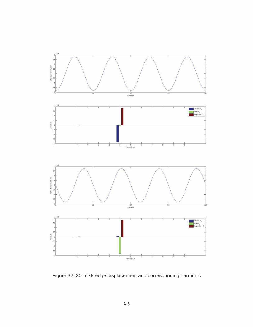
Figure 32: 30° disk edge displacement and corresponding harmonic

A 9
Figure 33: 45° disk edge displacement and corresponding harmonic
A 10
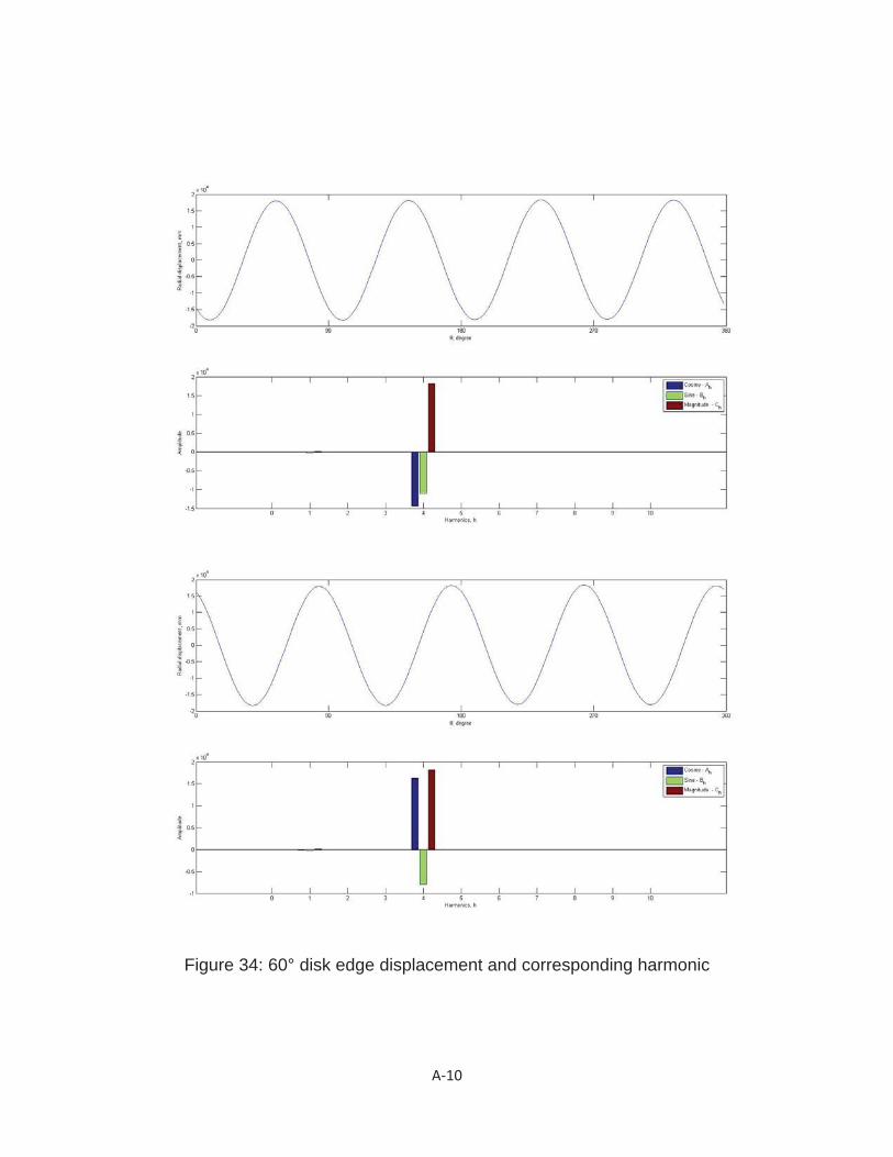
Figure 34: 60° disk edge displacement and corresponding harmonic

A 11
Figure 35: 0° finger base displacement and corresponding harmonic
A 12
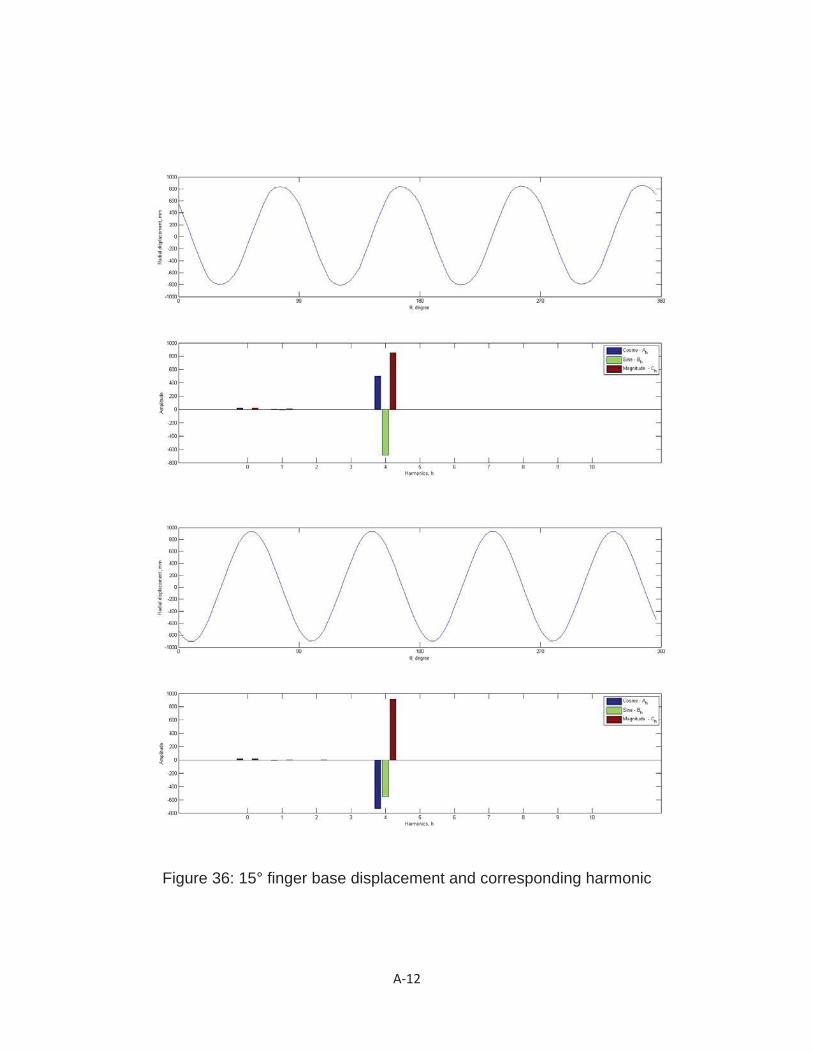
Figure 36: 15° finger base displacement and corresponding harmonic
A 13
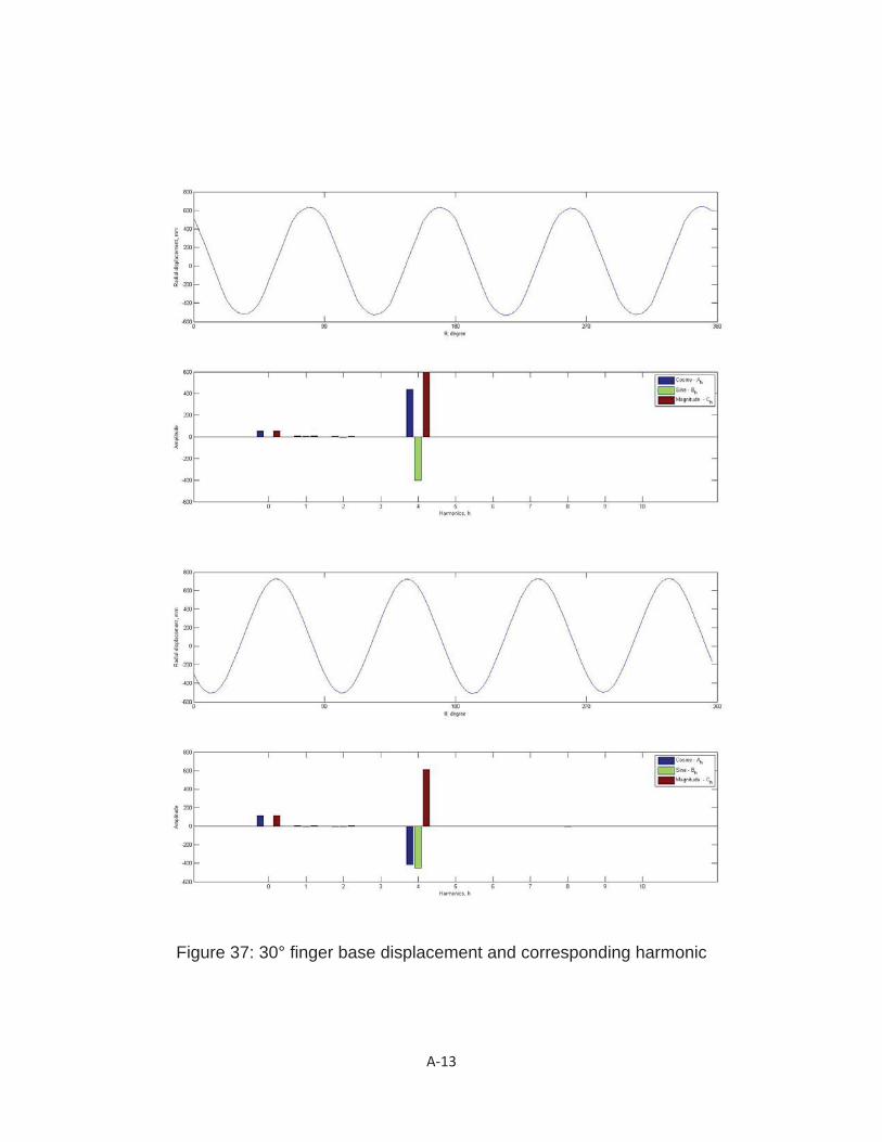
Figure 37: 30° finger base displacement and corresponding harmonic
A 14
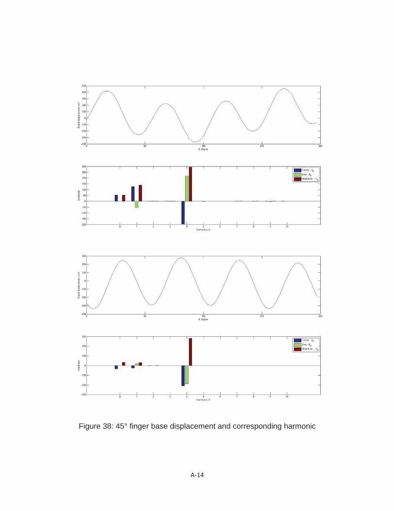
Figure 38: 45° finger base displacement and corresponding harmonic

A 15
Figure 39: 60° finger base displacement and corresponding harmonic