Embed Size (px)
Citation preview

International Journal of Scientific & Engineering Research Volume 2, Issue 10, Oct-2011 1 ISSN 2229-5518
IJSER © 2011 http://www.ijser.org
Design Aids of Flexural Members and Beam-Columns Based on Limit State Method
Prof. Ravindra Bhimarao kulkarni, Vikas Arjun Patil
ABSTRACT: The latest version of the Code of Practice for general construction in steel, IS 800-2007 is based on Limit State Method of design. The design concept is totally changed in comparison to earlier code IS-800-1984 which is based on elastic method. The design based on limit state method involves many equations and parameters. Therefore the design of steel structural members and connections involves tedious equations. In the present work, the detailed study has been carried out on the design of flexure members and beam-columns for channel section and effort is made to prepare design aids in the form of graphs, which is very useful to the practicing Structural Engineers. The use of charts for the design of flexure members and beam-columns will save the steel designer’s time considerably.
KEYWORDS: IS:800-2007, Factored load.
—————————— ——————————
1. Introduction
The structural/civil Designer has to ensure that the structures and facilities he designs are (i) fit for their purpose (ii) safe and (iii) economical and durable. Thus safety is one of the paramount responsibilities of the designer. However, it is difficult to assess at the design stage how safe a proposed design will actually be – consistent with economy. There is, in fact, a great deal of uncertainty about the many factors, which influence both safety and economy. Firstly, there is a natural variability in the material strengths and secondly it is impossible to predict the loading, which a structure (e.g. a building) may be subjected to on a future occasion. Thus uncertainties affecting the safety of a structure are due to
Uncertainty about loading Uncertainty about material strength and Uncertainty about structural dimensions and
behaviour. These uncertainties together make it impossible for a designer to guarantee that a structure will be absolutely safe. ______________________________________________
Vikas Arjun Patil is currently pursuing master degree in Structural engineering in Gogte Institute of Technology Belgaum (Karnataka), INDIA, PH-09964937979. E-mail: [email protected]
Prof. Ravindra Bhimarao kulkarni is assistant professor in the Department of Civil engineering in Gogte Institute of Technology Belgaum (Karnataka), INDIA. PH-09480398630 .E-mail: [email protected]
All that the designer could ensure is that the risk of failure is extremely small, despite the uncertainties. Earlier for designing steel structures working stress method is used (IS: 800-1984). Now designing done using limit state method (IS: 800-2007).
Design is basically a trial and error process, initially a section is assumed and it is checked, for its capacity to withstand the applied load. In case of design of steel structural elements according to IS: 800-2007, no ready to-use design tools are available to aid the initial selection.
2. OVERVIEW OF DESIGN EQUATIONS AS PER IS: 800-2007
2.1 Effective Span of Beams
The effective span of a beam shall be taken as the distance between the centre of the supports, except where the point of application of the reaction is taken as eccentric at the support, when it shall be permissible to take the effective span as the length between the assumed lines of the reactions.
2.2 Design bending strength of laterally Supported Beams The design bending strength of beams, adequately supported against buckling (laterally supported beams) is governed by yielding stress. The factored design moment, M at any section, in a beam due to external actions shall satisfy M ≤ Md
International Journal of Scientific & Engineering Research Volume 2, Issue 10, Oct-2011 2 ISSN 2229-5518
IJSER © 2011 http://www.ijser.org
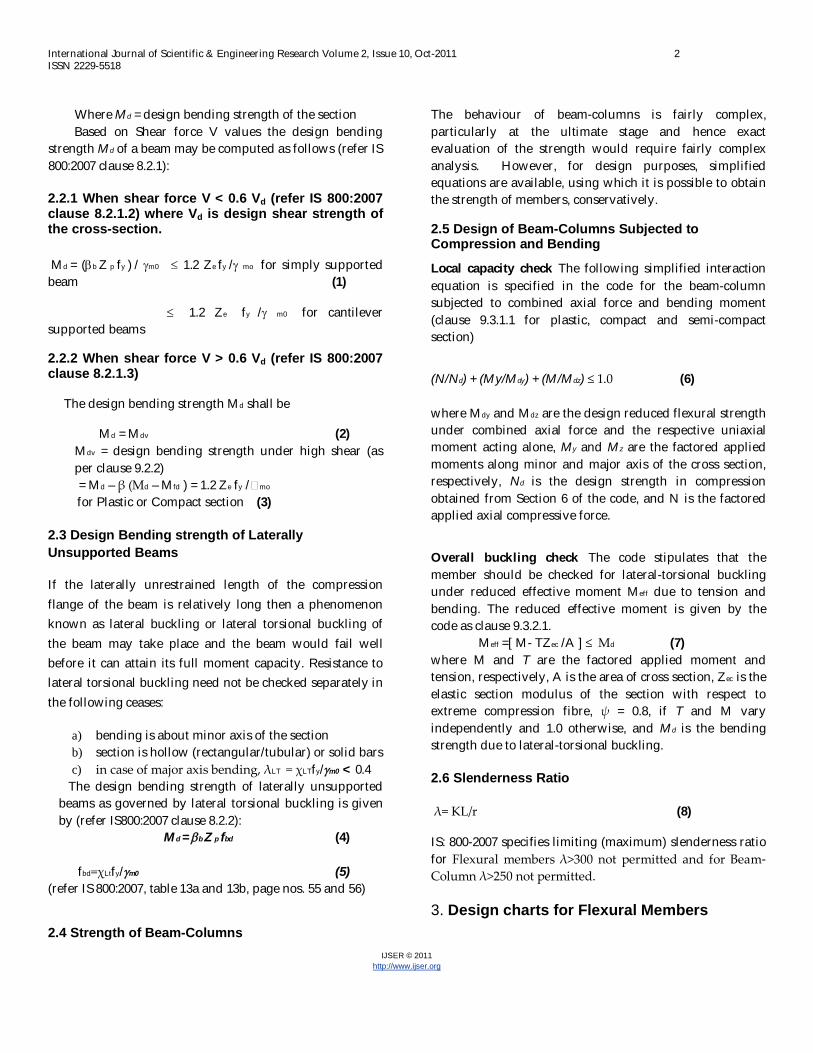
Where Md = design bending strength of the section Based on Shear force V values the design bending
strength Md of a beam may be computed as follows (refer IS 800:2007 clause 8.2.1):
2.2.1 When shear force V < 0.6 Vd (refer IS 800:2007 clause 8.2.1.2) where Vd is design shear strength of the cross-section.
Md = (b Z p fy ) / m0 1.2 Ze fy / mo for simply supported beam (1)
1.2 Ze fy / m0 for cantilever supported beams
2.2.2 When shear force V > 0.6 Vd (refer IS 800:2007 clause 8.2.1.3)
The design bending strength Md shall be
Md = Mdv (2) Mdv = design bending strength under high shear (as per clause 9.2.2) = Md – β (Md – Mfd ) = 1.2 Ze fy /�mo for Plastic or Compact section (3)
2.3 Design Bending strength of Laterally Unsupported Beams
If the laterally unrestrained length of the compression flange of the beam is relatively long then a phenomenon known as lateral buckling or lateral torsional buckling of the beam may take place and the beam would fail well before it can attain its full moment capacity. Resistance to lateral torsional buckling need not be checked separately in the following ceases:
a) bending is about minor axis of the section b) section is hollow (rectangular/tubular) or solid bars c) in case of major axis bending, λLT = χLTfy/m0 < 0.4
The design bending strength of laterally unsupported beams as governed by lateral torsional buckling is given by (refer IS800:2007 clause 8.2.2):
Md = b Z p fbd (4) fbd=χLtfy/m0 (5)
(refer IS 800:2007, table 13a and 13b, page nos. 55 and 56)
2.4 Strength of Beam-Columns
The behaviour of beam-columns is fairly complex, particularly at the ultimate stage and hence exact evaluation of the strength would require fairly complex analysis. However, for design purposes, simplified equations are available, using which it is possible to obtain the strength of members, conservatively.
2.5 Design of Beam-Columns Subjected to Compression and Bending
Local capacity check The following simplified interaction equation is specified in the code for the beam-column subjected to combined axial force and bending moment (clause 9.3.1.1 for plastic, compact and semi-compact section)
(N/Nd) + (My/Mdy) + (M/Mdz) ≤ 1.0 (6) where Mdy and Mdz are the design reduced flexural strength under combined axial force and the respective uniaxial moment acting alone, My and Mz are the factored applied moments along minor and major axis of the cross section, respectively, Nd is the design strength in compression obtained from Section 6 of the code, and N is the factored applied axial compressive force.
Overall buckling check The code stipulates that the member should be checked for lateral-torsional buckling under reduced effective moment Meff due to tension and bending. The reduced effective moment is given by the code as clause 9.3.2.1. Meff =[ M- TZec /A ] ≤ Md (7) where M and T are the factored applied moment and tension, respectively, A is the area of cross section, Zec is the elastic section modulus of the section with respect to extreme compression fibre, ψ = 0.8, if T and M vary independently and 1.0 otherwise, and Md is the bending strength due to lateral-torsional buckling. 2.6 Slenderness Ratio λ= KL/r (8)
IS: 800-2007 specifies limiting (maximum) slenderness ratio for Flexural members λ>300 not permitted and for Beam-Column λ>250 not permitted. 3. Design charts for Flexural Members

International Journal of Scientific & Engineering Research Volume 2, Issue 10, Oct-2011 3 ISSN 2229-5518
IJSER © 2011 http://www.ijser.org
The Charts have been prepared based on IS: 800-2007 for laterally supported and laterally unsupported beams. The procedure adopted is demonstrated with the design examples given below.
3.1 DESIGN EXAMPLE
Example1. Laterally Supported Beam
An ISJC 100 section is used as a beam over a span of 1 m, with simply supported ends. Determine the maximum factored uniformly distributed load that the beam can carry if the ends are restrained against torsion but compression flange is laterally supported.
Solution: For ISJC 150, [11] h = 100 mm, tw = 3 mm, Ze = 24800 mm3, Zp = 28380 mm3 Design capacity of the section Md = b Z p fy / m0
= (1.0 x 28380 x 250) / 1.1 = 6450000 N-mm
1.2 Ze fy / mo (1.2 x 24800 x 250) / 1.1 = 6763636 N-mm
Design Factored load
W=8*Md/l2= (8*6450000) / (1000*1000) = 51.60kN/m
Design shear strength
Vd = (fy *h * tw ) /( sq(3) * mo ) = (250*100*3)/(sq(3)*1.1)
= 39364.8N
Check for V < 0.6 Vd
Shear force V = W*L/2 = (51.60*1000) / 2 = 25800 N
0.6 Vd = 0.6*39364.8= 23618.9 N, Hence V > 0.6 Vd
= (2V/ Vd-1)2 = [((2*25800) / 23618.9) – 1]2 = 0.10
Zfd= Zp – Aw*Yw
= (28380 – ((100*3*100)/ 4)) = 20880 mm3
Mfd= (Zfd*fy) / m0 = (20880*250) / 1.1 = 4745455 N-mm
Mdv = Md – β (Md – Mfd ) = 1.2 Ze fy /�mo
= 6450000 – 0.1*(6450000 – 4745455) = 6285330 N- mm
W=8*Mdv/l2 = (8*6285330) / (1000*1000) = 50.28 kN/m
The design charts have been prepared effective span (mm) Vs Factored load (kN/m) based on the above example.
Fig.1 Graph is plotted factored load Vs effective span for ISJC.
ISJC 100
ISJC 125
ISJC 150
ISJC 175
ISJC 200
0
20
40
60
80
100
120
140
160
180
0 5000 10000 15000
FAC
TO
RE
D L
OA
D (
kN/m
)
EFFECTIVE SPAN (mm)
LATERALLY SUPPORTED BEAM FOR ISJC SECTIONS
ISJC 100ISJC 125ISJC 150ISJC 175ISJC 200

International Journal of Scientific & Engineering Research Volume 2, Issue 10, Oct-2011 4 ISSN 2229-5518
IJSER © 2011 http://www.ijser.org
Fig.2 Graph is plotted factored load Vs effective span for ISLC.
Fig.3 Graph is plotted factored load Vs effective span for ISLC.
Fig.4 Graph is plotted factored load Vs effective span for ISMC.
Fig.5 Graph is plotted factored load Vs effective span for ISMC.
ISLC 75
ISLB 100
ISLC 125
ISLC 150
ISLC 175
ISLC 200
0
50
100
150
200
250
300
0 5000 10000 15000
FAC
TO
RE
D L
OA
D (k
N/m
)
EFFECTIVE SPAN (mm)
LATERALLY SUPPORTED BEAM FOR ISLC SECTIONS
ISLC 75
ISLC 100
ISLC 125
ISLC 150
ISLC 175
ISLC 200
ISLC 225
ISLC 250
ISLC 300
ISLC 350
0
100
200
300
400
500
600
700
800
900
0 5000 10000 15000
FAC
TO
RE
D L
OA
D (k
N/m
)
EFFECTIVE SPAN (mm)
LATERALLY SUPPORTED BEAM FOR ISLC SECTIONS
ISLC 225
ISLC 250
ISLC 300
ISLC 350
ISLC 400
ISMC 75
ISLB 100
ISMC 125
ISMC 150
ISMC 175
ISMC 200
0
50
100
150
200
250
300
0 5000 10000 15000FA
CT
OR
ED
LO
AD
(kN
/m)
EFFECTIVE SPAN (mm)
LATERALLY SUPPORTED BEAM FOR ISMC SECTIONS
ISMC 75
ISMC 100
ISMC 125
ISMC 150
ISMC 175
ISMC 200
ISMC 225
ISMC 250
ISMC 300
ISMC 350
ISMC 400
0
100
200
300
400
500
600
700
800
900
1000
0 2000 4000 6000 8000 10000 12000
FAC
TO
RE
D L
OA
D (k
N/m
)
EFFECTIVE SPAN (mm)
LATERALLY SUPPORTED BEAM FOR ISMC SECTIONS
ISMC 225
ISMC 250
ISMC 300
ISMC 350
ISMC 400

International Journal of Scientific & Engineering Research Volume 2, Issue 10, Oct-2011 5 ISSN 2229-5518
IJSER © 2011 http://www.ijser.org
Example2. Laterally Unsupported Beam
An ISJC 100 section is used as a beam over a span of 1 m, with simply supported ends. Determine the maximum factored uniformly distributed load that the beam can carry if the ends are restrained against torsion but compression flange is laterally unsupported.
Solution:
For ISJC 100[11] h = 100 mm, tf = 5.1 mm, tw = 3 mm, ryy =14.2mm, Effective length = 6 m. Area =741 mm2 KL/r = ( 1*100 0) / 14.2 =70.42 h/t = 100/5.1 = 19.60 From Table 14 of IS 800: 2007
fcrb values as shown below: h/t 18 19.60 20
KL/r
70 587.4 X 562.9
70.42 …….. M
80 478.4 Y 455.3
To get the value for h/t = 19.60 and
KL/r = 70.42 it needs double linear interpolation
First get the values at X and Y corresponding to h/t = 19.60
To get the value at X (KL/r = 70, h/tf = 19.60)
fcrb = 587.4-1.60/2 (587.4– 562.9) = 567.704 N/mm2
To get the value at Y (KL/r = 80, h/tf = 19.60)
fcrb = 478.4-1.60/2(478.4– 455.3) = 459.83 N/mm2
...The value of fcrb at h/tf = 19.60 and KL/r = 70.42.
To get the value at M.
fcrb = 567.704 -0.42/10 (567.704 – 459.83) = 563.145 N/mm2
Referring to Table 13(a) in IS 800-2007, for fy = 250 N/mm2,
We find fbd= 188.6 N/mm2 fcrb = 500.
And fbd = 197.7 N/mm2 for fcrb = 600.
... For fcrb = 563.145
fbd = 188.6 + 63.145/100(197.7 -188.6) = 194.3N/mm2
Hence it belongs to class 2 (compact) category.
... Md = βb Zp fbd
βb = 1, Zp = 28380 mm3, fbd = 194.3 N/mm2
...Md = 1 x 28380x 194.3 = 5.515 kN-m
If udl w is in kN/m, then WL2/8 = Md
Wx 12/8 =5.515 =>W = 44.12 kN/m.
The design charts have been prepared effective span (mm) Vs Factored load (kN/m) based on the above example.
Fig.6 Graph is plotted for factored load Vs effective span.
ISJC 100
ISJC 125
ISJC 150
ISJC 175
ISJC 200
0
50
100
150
200
250
300
350
400
450
500
0 2000 4000 6000 8000
FAC
TO
RE
D L
OA
D (k
N/m
)
EFFECTIVE SPAN (mm)
LATERALLY UNSUPPORTED BEAM FOR ISJC SECTIONS
ISJC 100
ISJC 125
ISJC 150
ISJC 175
ISJC 200

International Journal of Scientific & Engineering Research Volume 2, Issue 10, Oct-2011 6 ISSN 2229-5518
IJSER © 2011 http://www.ijser.org
Fig.7 Graph is plotted for factored load Vs effective span.
Fig.8 Graph is plotted for factored load Vs effective span.
Fig.9 Graph is plotted for factored load Vs effective span.
Fig.10 Graph is plotted for factored load Vs effective span.
ISLC 75
ISLC 100
ISLC 125
ISLC 150
ISLC 175
ISLC 200
0
100
200
300
400
500
600
700
0 5000 10000 15000
FAC
TO
RE
D L
OA
D (k
N/m
)
EFFECTIVE SPAN (mm)
LATERALLY UNSUPPORTED BEAM FOR ISLC SECTIONS
ISLC 75ISLC 100ISLC 125ISLC 150ISLC 175ISLC 200
ISLC 225
ISLC 250
ISLC 300
ISLC 350
ISLC 400
0
200
400
600
800
1000
1200
1400
1600
0 5000 10000
FAC
TO
RE
DLO
AD
(k
N/m
)
EFFECTIVE SPAN (mm)
LATERALLY UNSUPPORTED BEAM FOR ISLC SECTIONS
ISLC 225
ISLC 250
ISLC 300
ISLC 350
ISLC 400
ISMC 75
ISMC 100
ISMC 125
ISMC 150
ISMC 175
ISMC 200
0
50
100
150
200
250
300
350
400
0 5000 10000FA
CT
OR
ED
LOA
D (
kN
/m)
EFFECTIVE SPAN (mm)
LATERALLY UNSUPPORTED BEAM FOR ISMC SECTIONS
ISMC 75
ISMC 100
ISMC 125
ISMC 150
ISMC 175
ISMC 200
ISMC 225
ISMC 250
ISMC 300
ISMC 350
ISMC 400
0
100
200
300
400
500
600
700
0 2000 4000 6000 8000 10000
FAC
TO
RE
D L
OA
D (K
N/m
)
EFFECTIVE SPAN (mm)
LATERALLY UNSUPPORTED BEAM FOR ISMC SECTIONS
ISMC 225
ISMC 250
ISMC 300
ISMC 350
ISMC 400

International Journal of Scientific & Engineering Research Volume 2, Issue 10, Oct-2011 7 ISSN 2229-5518
IJSER © 2011 http://www.ijser.org
4. Design Charts for Beam-columns:
The Charts have been prepared based on IS: 800-2007 for beam-columns. The procedure adopted is demonstrated with the design example given below.
4.1 DESIGN EXAMPLE
Example1. Beam-Column An ISJC 100 section is used as a beam column of length 1m, with flexible joints. Determine the maximum factored axial load that the beam-column can carry safely. Solution: For ISJC 100 [11] h = 100 mm, , tf = 5.1 mm, tw = 3 mm, ryy =14.2mm, Effective length = 6 m. Area =741 mm2 KL/r = ( 1*100 0) / 14.2 =70.42 h/t = 100/5.1 = 19.60
From Table 14 of IS 800: 2007
fcrb values as shown below: h/t 18 19.60 20
KL/r
70 587.4 X 562.9
70.42 …….. M
80 478.4 Y 455.3
To get the value for h/t = 19.60 and
KL/r = 70.42 it needs double linear interpolation
First get the values at X and Y corresponding to h/t = 19.60
To get the value at X (KL/r = 70, h/tf = 19.60)
fcrb = 587.4-1.60/2 (587.4– 562.9) = 567.704 N/mm2
To get the value at Y (KL/r = 80, h/tf = 19.60)
fcrb = 478.4-1.60/2(478.4– 455.3) = 459.83 N/mm2
...The value of fcrb at h/tf = 19.60 and KL/r = 70.42.
To get the value at M.
fcrb = 567.704 -0.42/10 (567.704 – 459.83) = 563.145 N/mm2
Referring to Table 13(a) in IS 800, for fy = 250 N/mm2,
We find fbd= 188.6 N/mm2 fcrb = 500.
And fbd = 197.7 N/mm2 for fcrb = 600.
... For fcrb = 563.145
fbd = 188.6 + 63.145/100(197.7 -188.6) = 194.3N/mm2
Hence it belongs to class 2 (compact) categories.
... Md = βb Zp fbd
βb = 1, Zp = 28380 mm3, fbd = 194.3 N/mm2
...Mdz = 1 x 28380x 194.3 = 5.5155 kN-m
Member buckling resistance in compression (clause 7.1.2)
Minor axis buckling, using curve (c)
From Table 9c of the code, for KL/r = 70.42 and fy=250 N/mm2
70 152 70.42 …………
80 136 fcr = 152 -0.42/10 (152 – 136) = 151.33 N/mm2
Pdy = Nd = fcr *A
Nd = (151.33 *741)/1000 =112.13 kN
We have calculated Nd and Md for ISJC 100.Now the Design factored axial load N is calculated by increasing factored moment M in the equation no.(4). The design charts have been prepared Factored moment (kN/m) Vs Factored axial load (kN) for different effective span based on the above example.
4.2 Design Charts for all ISJC sections.

International Journal of Scientific & Engineering Research Volume 2, Issue 10, Oct-2011 8 ISSN 2229-5518
IJSER © 2011 http://www.ijser.org
Fig.11 Graph is plotted for Factored Axial Load Vs Factored Moment for ISJC 100.
Fig.12 Graph is plotted for Factored Axial Load Vs Factored Moment for ISJC 125.
Fig.13 Graph is plotted for Factored Axial Load Vs Factored Moment for ISJC 150.
Fig.15 Graph is plotted for Factored Axial Load Vs Factored Moment for ISJC 175.
0.5m
0.75m
1m
1.5m
2m2.5m
3m
0
20
40
60
80
100
120
140
160
0 2 4 6 8
FAC
TO
RE
D A
XIA
L L
OA
D (k
N)
FACTORED MOMENT (kNm)
DESIGN CHART FOR BEAM COLUMN ISJC 100 BY LSM FOR VARYING EFFECTIVE SPAN
0.5m
0.75m
1m
1.5m
2m
2.5m
3m
0.5 m0.75 m1 m
1.5 m2 m2.5 m3 m
0
50
100
150
200
250
0 5 10 15
FAC
TO
RE
D A
XIA
L L
OA
D (k
N)
FACTORED MOMENT (kNm)
DESIGN CHART FOR BEAM COLUMN ISJC 125 BY LSM FOR VARYING EFFECTIVE SPAN
0.5 m0.75 m
1 m
1.5 m2 m
2.5 m
3 m
0.5 m0.75 m
1 m
1.5 m
2 m2.5 m3 m
4 m0
50
100
150
200
250
300
0 5 10 15 20FA
CT
OR
ED
AX
IAL
LO
AD
(kN
)
FACTORED MOMENT (kNm)
DESIGN CHART FOR BEAM COLUMN ISJC 150 BY LSM FOR VARYING EFFECTIVE SPAN
0.5 m
0.75 m
1 m
1.5 m
2 m
2.5 m
3 m
4 m
0.5 m0.75 m
1 m
1.5 m
2 m2.5 m
3 m4 m
0
50
100
150
200
250
300
350
0 10 20 30
FAC
TO
RE
D A
XIA
L L
OA
D (k
N)
FACTORED MOMENT (kNm)
DESIGN CHART FOR BEAM COLUMN ISJC 175 BY LSM FOR VARYING EFFECTIVE SPAN
0.5 m
0.75 m
1 m
1.5 m
2 m
2.5 m
3 m
4 m

International Journal of Scientific & Engineering Research Volume 2, Issue 10, Oct-2011 9 ISSN 2229-5518
IJSER © 2011 http://www.ijser.org
Fig.14 Graph is plotted for Factored Axial Load Vs Factored Moment for ISJC 200.
4.3 Design Charts for all ISLC sections
Fig.16 Graph is plotted for Factored Axial Load Vs Factored Moment for ISLC 75.
Fig.17 Graph is plotted for Factored Axial Load Vs Factored Moment for ISLC 100.
Fig.18 Graph is plotted for Factored Axial Load Vs Factored Moment for ISLC 125.
0.5 m0.75 m
1 m
1.5 m
2 m
2.5 m3 m4 m5 m
0
50
100
150
200
250
300
350
400
450
0 10 20 30 40
FAC
TO
RE
D A
XIA
L L
OA
D (k
N)
FACTORED MOMENT (kNm)
DESIGN CHART FOR BEAM COLUMN ISJC 200 BY LSM FOR VARYING EFFECTIVE SPAN
0.5 m
0.75 m
1 m
1.5 m
2 m
2.5 m
3 m
4 m
5 m
0.5 m0.75 m
1 m
1.5 m2 m2.5 m3 m0
20
40
60
80
100
120
140
160
0 2 4 6
FAC
TO
RE
D A
XIA
L L
OA
D (k
N)
FACTORED MOMENT (kNm)
DESIGN CHART FOR BEAM COLUMN ISLC 75 BY LSM FOR VARYING EFFECTIVE SPAN
0.5 m
0.75 m
1 m
1.5 m
2 m
2.5 m
3 m
0.5 m0.75 m
1 m
1.5 m2 m2.5 m3 m0
50
100
150
200
250
0 5 10FA
CT
OR
ED
AX
IAL
LO
AD
(kN
)
FACTORED MOMENT (kNm)
DESIGN CHART FOR BEAM COLUMN ISLC 100 BY LSM FOR VARYING EFFECTIVE SPAN
0.5 m
0.75 m
1 m
1.5 m
2 m
2.5 m
3 m
0.5 m0.75 m1 m
1.5 m
2 m2.5 m3 m4 m5 m0
50
100
150
200
250
300
350
0 5 10 15 20
FAC
TO
RE
D A
XIA
L L
OA
D (k
N)
FACTORED MOMENT (kNm)
DESIGN CHART FOR BEAM COLUMN ISLC 125 BY LSM FOR VARYING EFFECTIVE SPAN
0.5 m
0.75 m
1 m
1.5 m
2 m
2.5 m
3 m
4 m
5 m

International Journal of Scientific & Engineering Research Volume 2, Issue 10, Oct-2011 10 ISSN 2229-5518
IJSER © 2011 http://www.ijser.org
Fig.19 Graph is plotted for Factored Axial Load Vs Factored Moment for ISLC 150.
Fig.20 Graph is plotted for Factored Axial Load Vs Factored Moment for ISLC 175.
Fig.21 Graph is plotted for Factored Axial Load Vs Factored Moment for ISLC 200.
Fig.22 Graph is plotted for Factored Axial Load Vs Factored Moment for ISLC 225.
0.5 m0.75 m
1 m
1.5 m
2 m
2.5 m3 m4 m5 m0
50
100
150
200
250
300
350
400
450
0 10 20 30
FAC
TO
RE
D A
XIA
L L
OA
D (k
N)
FACTORED MOMENT (kNm)
DESIGN CHART FOR BEAM COLUMN ISLC 150 BY LSM FOR VARYING EFFECTIVE SPAN
0.5 m
0.75 m
1 m
1.5 m
2 m
2.5 m
3 m
4 m
5 m
0.5 m0.75 m
1 m
1.5 m2 m2.5 m3 m4 m5 m0
100
200
300
400
500
600
0 10 20 30 40
FAC
TO
RE
D A
XIA
L L
OA
D (k
N)
FACTORED MOMENT (kNm)
DESIGN CHART FOR BEAM COLUMN ISLC 175 BY LSM FOR VARYING EFFECTIVE SPAN
0.5 m
0.75 m
1 m
1.5 m
2 m
2.5 m
3 m
4 m
5 m
0.5 m0.75 m
1 m
1.5 m
2 m2.5 m3 m4 m5 m0
100
200
300
400
500
600
700
0 20 40 60FA
CT
OR
ED
AX
IAL
LO
AD
(kN
)FACTORED MOMENT (kNm)
DESIGN CHART FOR BEAM COLUMN ISLC 200 BY LSM FOR VARYING EFFECTIVE SPAN
0.5 m
0.75 m
1 m
1.5 m
2 m
2.5 m
3 m
4 m
5 m
0.5 m0.75 m
1 m
1.5 m
2 m
2.5 m3 m
4 m5 m
0
100
200
300
400
500
600
700
800
0 20 40 60 80
FAC
TO
RE
D A
XIA
L L
OA
D (k
N)
FACTORED MOMENT (kNm)
DESIGN CHART FOR BEAM COLUMN ISLC 225 BY LSM FOR VARYING EFFECTIVE SPAN
0.5 m
0.75 m
1 m
1.5 m
2 m
2.5 m
3 m
4 m
5 m

International Journal of Scientific & Engineering Research Volume 2, Issue 10, Oct-2011 11 ISSN 2229-5518
IJSER © 2011 http://www.ijser.org
Fig.23 Graph is plotted for Factored Axial Load Vs Factored Moment for ISLC 250.
Fig.24 Graph is plotted for Factored Axial Load Vs Factored Moment for ISLC 300.
Fig.25 Graph is plotted for Factored Axial Load Vs Factored Moment for ISLC 350.
Fig.26 Graph is plotted for Factored Axial Load Vs Factored Moment for ISLC 400.
0.75 m1 m1.5 m
2 m
2.5 m3 m
4 m5 m6 m7 m
0
100
200
300
400
500
600
700
800
900
0 50 100
FAC
TO
RE
D A
XIA
L L
OA
D (k
N)
FACTORED MOMENT (kNm)
DESIGN CHART FOR BEAM COLUMN ISLC 250 BY LSM FOR VARYING EFFECTIVE SPAN
0.75 m
1 m
1.5 m
2 m
2.5 m
3 m
4 m
5 m
6 m
7 m
0.75 m1 m1.5 m
2 m
2.5 m
3 m
4 m5 m6 m7 m
0
100
200
300
400
500
600
700
800
900
1000
0 20 40 60 80 100 120
FAC
TO
RE
D A
XIA
L L
OA
D (k
N)
FACTORED MOMENT (kNm)
DESIGN CHART FOR BEAM COLUMN ISLC 300 BY LSM FOR VARYING EFFECTIVE SPAN
0.75 m
1 m
1.5 m
2 m
2.5 m
3 m
4 m
5 m
6 m
7 m
0.75 m1 m
1.5 m
2 m
2.5 m
3 m
4 m5 m6 m7 m
0
200
400
600
800
1000
1200
0 50 100 150
FAC
TO
RE
D A
XIA
L L
OA
D (k
N)
FACTORED MOMENT (kNm)
DESIGN CHART FOR BEAM COLUMN ISLC 350 BY LSM FOR VARYING EFFECTIVE SPAN
0.75 m
1 m
1.5 m
2 m
2.5 m
3 m
4 m
5 m
6 m
7 m
0.75 m1 m
1.5 m
2 m
2.5 m
3 m
4 m5 m6 m7 m
0
200
400
600
800
1000
1200
1400
0 50 100 150 200
FAC
TO
RE
D A
XIA
L L
OA
D (k
N)
FACTORED MOMENT (kNm)
DESIGN CHART FOR BEAM COLUMN ISLC 400 BY LSM FOR VARYING EFFECTIVE SPAN
0.75 m
1 m
1.5 m
2 m
2.5 m
3 m
4 m
5 m
6 m
7 m

International Journal of Scientific & Engineering Research Volume 2, Issue 10, Oct-2011 12 ISSN 2229-5518
IJSER © 2011 http://www.ijser.org
4.4 design Charts for all ISMC sections
Fig.27 Graph is plotted for Factored Axial Load Vs Factored Moment for ISMC 75.
Fig.28 Graph is plotted for Factored Axial Load Vs Factored Moment for ISMC 100.
Fig.29 Graph is plotted for Factored Axial Load Vs Factored Moment for ISMC 125.
Fig.30 Graph is plotted for Factored Axial Load Vs Factored Moment for ISMC 150.
0.5 m0.75 m
1 m
1.5 m2 m2.5 m3 m0
20
40
60
80
100
120
140
160
180
0 2 4 6
FAC
TO
RE
D A
XIA
L L
OA
D (k
N)
FACTORED MOMENT (kNm)
DESIGN CHART FOR BEAM COLUMN ISMC 75 BY LSM FOR VARYING EFFECTIVE SPAN
0.5 m
0.75 m
1 m
1.5 m
2 m
2.5 m
3 m
0.5 m
0.75 m1 m
1.5 m2 m2.5 m3 m0
20
40
60
80
100
120
140
160
180
0 2 4 6
FAC
TO
RE
D A
XIA
L L
OA
D (k
N)
FACTORED MOMENT (kNm)
DESIGN CHART FOR BEAM COLUMN ISMC 100 BY LSM FOR VARYING EFFECTIVE SPAN
0.5 m
0.75 m
1 m
1.5 m
2 m
2.5 m
3 m
0.5 m0.75 m
1 m
1.5 m2 m2.5 m3 m4 m
0
50
100
150
200
250
300
350
400
0 5 10 15 20FA
CT
OR
ED
AX
IAL
LO
AD
(kN
)FACTORED MOMENT (kNm)
DESIGN CHART FOR BEAM COLUMN ISMC 125 BY LSM FOR VARYING EFFECTIVE SPAN
0.5 m
0.75 m1 m
1.5 m
2 m
2.5 m
3 m
0.5 m0.75 m
1 m
1.5 m
2 m2.5 m3 m4 m5 m0
50
100
150
200
250
300
350
400
450
500
0 10 20 30
FAC
TO
RE
D A
XIA
L L
OA
D (k
N)
FACTORED MOMENT (kNm)
DESIGN CHART FOR BEAM COLUMN ISMC 150 BY LSM FOR VARYING EFFECTIVE SPAN
0.5 m
0.75 m
1 m
1.5 m
2 m
2.5 m
3 m
4 m
5 m

International Journal of Scientific & Engineering Research Volume 2, Issue 10, Oct-2011 13 ISSN 2229-5518
IJSER © 2011 http://www.ijser.org
Fig.31 Graph is plotted for Factored Axial Load Vs Factored Moment for ISMC 175.
Fig.32 Graph is plotted for Factored Axial Load Vs Factored Moment for ISMC 200.
Fig.33 Graph is plotted for Factored Axial Load Vs Factored Moment for ISMC 225.
Fig.34 Graph is plotted for Factored Axial Load Vs Factored Moment for ISMC 250.
0.5 m0.75 m
1 m
1.5 m
2 m
2.5 m3 m4 m5 m0
100
200
300
400
500
600
0 10 20 30 40
FAC
TO
RE
D A
XIA
L L
OA
D (k
N)
FACTORED MOMENT (kNm)
DESIGN CHART FOR BEAM COLUMN ISMC 175 BY LSM FOR VARYING EFFECTIVE SPAN
0.5 m
0.75 m
1 m
1.5 m
2 m
2.5 m
3 m
4 m
5 m
0.5 m0.75 m
1 m
1.5 m
2 m
2.5 m3 m4 m5 m0
100
200
300
400
500
600
700
0 20 40 60
FAC
TO
RE
D A
XIA
L L
OA
D (k
N)
FACTORED MOMENT (kNm)
DESIGN CHART FOR BEAM COLUMN ISMC 200 BY LSM FOR VARYING EFFECTIVE SPAN
0.5 m
0.75 m
1 m
1.5 m
2 m
2.5 m
3 m
4 m
5 m
0.5 m0.75 m
1 m
1.5 m
2 m
2.5 m3 m
4 m5 m
0
100
200
300
400
500
600
700
800
0 20 40 60 80FA
CT
OR
ED
AX
IAL
LO
AD
(kN
)
FACTORED MOMENT (kNm)
DESIGN CHART FOR BEAM COLUMN ISMC 225 BY LSM FOR VARYING EFFECTIVE SPAN
0.5 m
0.75 m
1 m
1.5 m
2 m
2.5 m
3 m
4 m
5 m
0.5 m0.75 m
1 m
1.5 m
2 m
2.5 m3 m
4 m5 m
0
100
200
300
400
500
600
700
800
900
1000
0 20 40 60 80 100
FAC
TO
RE
D A
XIA
L L
OA
D (k
N)
FACTORED MOMENT (kNm)
DESIGN CHART FOR BEAM COLUMN ISMC 250 BY LSM FOR VARYING EFFECTIVE SPAN
0.5 m
0.75 m1 m
1.5 m
2 m
2.5 m
3 m
4 m
International Journal of Scientific & Engineering Research Volume 2, Issue 10, Oct-2011 14 ISSN 2229-5518
IJSER © 2011 http://www.ijser.org
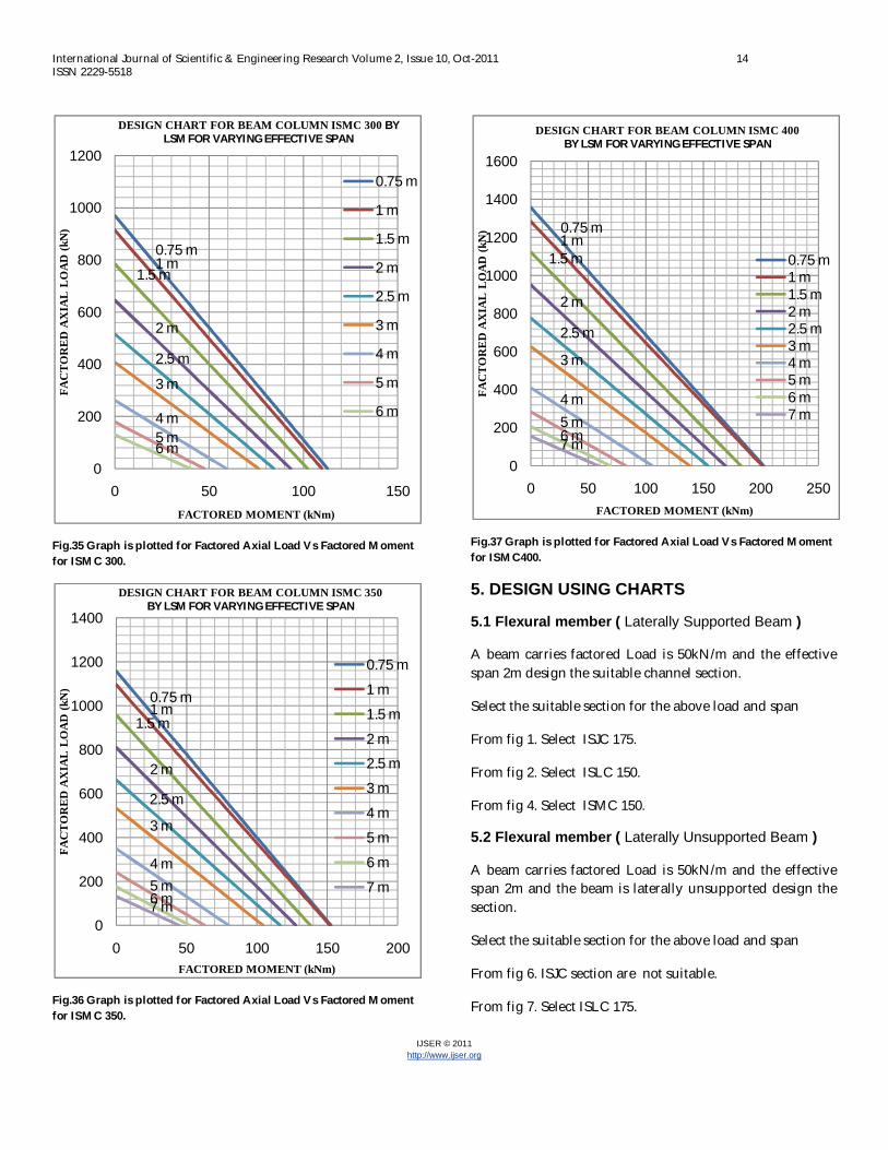
Fig.35 Graph is plotted for Factored Axial Load Vs Factored Moment for ISMC 300.
Fig.36 Graph is plotted for Factored Axial Load Vs Factored Moment for ISMC 350.
Fig.37 Graph is plotted for Factored Axial Load Vs Factored Moment for ISMC400.
5. DESIGN USING CHARTS
5.1 Flexural member ( Laterally Supported Beam )
A beam carries factored Load is 50kN/m and the effective span 2m design the suitable channel section.
Select the suitable section for the above load and span
From fig 1. Select ISJC 175.
From fig 2. Select ISLC 150.
From fig 4. Select ISMC 150.
5.2 Flexural member ( Laterally Unsupported Beam )
A beam carries factored Load is 50kN/m and the effective span 2m and the beam is laterally unsupported design the section.
Select the suitable section for the above load and span
From fig 6. ISJC section are not suitable.
From fig 7. Select ISLC 175.
0.75 m1 m
1.5 m
2 m
2.5 m
3 m
4 m5 m6 m
0
200
400
600
800
1000
1200
0 50 100 150
FAC
TO
RE
D A
XIA
L L
OA
D (k
N)
FACTORED MOMENT (kNm)
DESIGN CHART FOR BEAM COLUMN ISMC 300 BY LSM FOR VARYING EFFECTIVE SPAN
0.75 m
1 m
1.5 m
2 m
2.5 m
3 m
4 m
5 m
6 m
0.75 m1 m
1.5 m
2 m
2.5 m
3 m
4 m5 m6 m7 m
0
200
400
600
800
1000
1200
1400
0 50 100 150 200
FAC
TO
RE
D A
XIA
L L
OA
D (k
N)
FACTORED MOMENT (kNm)
DESIGN CHART FOR BEAM COLUMN ISMC 350 BY LSM FOR VARYING EFFECTIVE SPAN
0.75 m
1 m
1.5 m
2 m2.5 m
3 m
4 m
5 m
6 m
7 m
0.75 m1 m
1.5 m
2 m
2.5 m
3 m
4 m5 m6 m7 m
0
200
400
600
800
1000
1200
1400
1600
0 50 100 150 200 250FA
CT
OR
ED
AX
IAL
LO
AD
(kN
)
FACTORED MOMENT (kNm)
DESIGN CHART FOR BEAM COLUMN ISMC 400 BY LSM FOR VARYING EFFECTIVE SPAN
0.75 m1 m1.5 m2 m2.5 m3 m4 m5 m6 m7 m

International Journal of Scientific & Engineering Research Volume 2, Issue 10, Oct-2011 15 ISSN 2229-5518
IJSER © 2011 http://www.ijser.org
From fig 9. Select ISMC 150.
5. 3 Beam-Column
A simply supported beam supports 50kN/m factored lateral load for an effective span of 3m. The beam is also subjected to factored axial load of 300kN. Select a suitable section.
Factored axial load = 300kN
Factored moment = (50*3*3)/8 =56.25 kNm
From fig 26. Select ISLC 400 (factored axial load 300kN and factored moment 60kNm)
From fig 37. select ISMC 400 (factored axial load 300kN and factored moment 70kNm)
6. CONCLUSION
Design charts for the design of steel sections made up of Indian standard channel sections. These design charts are presented based on IS: 800-2007.
The graphs have been prepared for the flexural members (Laterally Supported and Unsupported) channel sections, which can be used to select the section directly for different effective span and the factored load (kN/m), the member can with stand. These graphs can be used as designed aids for selecting steel sections.
In case of Beam-Columns (channel sections), the design aid graphs are prepared for the factored axial load against factored moment which is a slopping straight line for different effective spans.
NOTATIONS
A = section area.
Ag = gross area of cross section in mm2.
E = modulus of elasticity.
Frb = elastic critical buckling stress.
fbd = design bending compressive stress.
fy = characteristic yield strength.
I = minimum moment of inertia.
KL = effective length of the member.
KL/r = effective slenderness ratio of the section.
L = actual length of column, beam.
Md = design bending strength of the section.
Mdv = design bending strength under high shear.
Mfd = plastic design strength of the area of the
cross section excluding the shear area, considering partial safety factor �mo.
Pd = critical buckling load.
r = appropriate radius of gyration.
t w = thickness of the web.
tf = thickness of flange .
V = factored applied shear force as governed by web yielding or web buckling. Vd = shear strength as governed by web
yielding or web buckling. Z = elastic section modulii of the cross- section. Ze = Elastic Section modulus.
Zp = Plastic Section modulus.
γmo = the partial safety factor for failure in
tension by yielding.
γm1 = partial safety factor for failure at ultimate
stress.
λ = non-dimensional effective slenderness
ratio.
χLt = bending stress reduction factor to account
for lateral torsional buckling.

International Journal of Scientific & Engineering Research Volume 2, Issue 10, Oct-2011 16 ISSN 2229-5518
IJSER © 2011 http://www.ijser.org
REFERENCE
[1] Teaching Resource in Design of Steel Structures IIT Madras, SERC Madras, Anna Univ., INSDAG
[2] Dr S R Satish Kumar and A.R.Santha Kumar, “Beam Columns”, Structural Engineering Laboratory, Dept. of Civil Engineering, IIT Madras, Chennai.
[3] Vinod I. Hosur and Aand N. Shetty , (2004) “Design charts for steel compression member as per 18:800-1984 and AISC-LRFD” Journal of Structural Engineering Vol. 30, No. 4, January- March 2004.
[4] J. Daniel Ronald Joseph, K. Balaji Roa and M. B. Anoop,(2010)“Probabilistic analysis of steel columns designed based on IS: 800-2007” ” Journal of Structural Engineering Vol. 37, No. 2, June-July 2010.
[5] N.S. Trahaie, (2004) “Biaxial Bending of Steel Angle Section Beams” Journal of Structural Engineering @ ASCE / April 2004, pg no.554-561.
[6] N.S.Trahaie, (2005)“Buckling and Torsion of Steel
Equal Angle Beams” Journal of Structural Engineering @ ASCE / March 2005, pg no.467-471.
[7] N.S.Trahaie, (2005) “Buckling and Torsion of Steel
Unequal Angle Beams” Journal of Structural Engineering @ ASCE / March 2005, pg no.474-480.
[8] D.S. Rajendra Prasad, (2010) “Design of Steel
Structures” (Compliance to IS 800:2007 code) Sapna Book House, 3rd Main Road, Gandhinagar, Banglore- 560009.
[9] V. Kalyanaraman, ”Design of Beam Columns” Dept. of Civil Engineering, IIT Madras, Chennai.
[10] Dr. N. Subramanian, (2008 ). Design of Steel Structures, Oxford University Press, New Delhi, 1240pp.
[11] IS 800:2007 (2007), Indian standard code of practice for General Construction in Steel, Bureau of Indian Standards, New Delhi, Dec.,143pp.


![SteelDesign Flexural Fu[1]](https://img.dokumen.tips/doc/110x75/577cd8e61a28ab9e78a242e9/steeldesign-flexural-fu1.jpg)