Embed Size (px)
Citation preview

Description of a Cognitive Radio Testbed based onUSRP Platforms and CogWave
Vincent Le Nir and Bart ScheersRoyal Military Academy, Dept. CISS
30, Avenue de la RenaissanceB-1000 Brussels BELGIUM.
Abstract—Today, many software defined radio (SDR) platformsare commercially available as off-the-shelf products at a veryreasonable price. The concept of cognitive radio (CR) is to havea network of SDRs which can autoconfigure and autonomouslychange its parameters (waveform, frequency, bandwidth, power)according to the user needs and the electromagnetic environ-ment. CogWave is an open-source software framework aimingat developing CR waveforms. Multiple waveforms have beenimplemented in CogWave, such as the multichannel DAA-OFDMwaveform, the DADS waveform, and GNU Radio waveforms.CogWave provides the means to implement different CR wave-forms and to develop rules to switch between different CRwaveforms during run-time according to the user needs andthe electromagnetic environment. A description of a CR testbedbased on USRP platforms and the CogWave framework is given.In the scenario, a jammer perturbs the data transmission betweentwo CR nodes. Results show that when the throughput dropsunder a predifined threshold, the CR nodes are able to switchfrom one waveform to another waveform while maintainingcommunication.
I. I NTRODUCTION
The aim of software defined radio (SDR) is to replace spe-cial analog hardware components by field programmable gatearrays (FPGA), digital signal processors (DSP) and generalpurpose processors (GPP) to allow fast-prototyping and tosupport multiple radio standards on a single reconfigurableplatform [1]. Today, many SDR platforms are commerciallyavailable as off-the-shelf products at a very reasonable price.The concept of cognitive radio (CR) is to have a network ofSDRs which can autoconfigure and autonomously change itsparameters (waveform, frequency, bandwidth, power) accord-ing to the user needs and the electromagnetic environment[2]. CogWave is an open-source software framework aimingat developing CR waveforms [3]. CogWave uses the Qt frame-work, the communications library IT++, the USRP universalhardware driver (UHD) and other librairies to enable real-time transmission between USRP devices. Multiple waveformshave been implemented in CogWave. The first waveform isthe multichannel orthogonal frequency division multiplexing(OFDM) waveform with detection and avoid (DAA) intro-duced in [4]. The second waveform is the delay and add directsequence (DADS) waveform with a short spreading sequenceintroduced in [5]. Other waveforms such as OFDM, BPSK,QPSK, GMSK, CPFSK etc. have been ported to CogWavefrom GNU Radio [6]. A CR node is composed of a host PCrunning the CogWave framework and a USRP. CogWave gives
the ability to the CR nodes to modify the waveform and itsparameters during run-time according to the user needs and theelectromagnetic environment. This paper gives a descriptiona CR testbed based on USRP platforms and the CogWaveframework with its two waveforms, i.e. the multichannelDAA-OFDM waveform and the DADS waveform. In thescenario, a jammer perturbs the data transmission betweentwo CR nodes. Results show that when the throughput dropsunder a predefined threshold, the CR nodes switch from theDADS to the multichannel DAA-OFDM automatically whilemaintaining communication. Section II provides a descriptionof the CogWave framework, the multichannel DAA-OFDMwaveform and the DADS waveform. A description of theCR testbed and results are given in Section III. Section IVconcludes this paper.
II. D ESCRIPTION OFCOGWAVE FRAMEWORK
This Section provides a description of the CogWave frame-work. The main objective of CogWave is to develop a libraryof waveforms and to develop rules to switch between thesewaveforms during run-time according to the user needs and theelectromagnetic environment. Multiple waveforms have beenimplemented in CogWave. The first waveform is the multi-channel DAA-OFDM waveform introduced in [4]. The multi-channel DAA-OFDM waveform uses energy-based sensing toadjust dynamically the channel and to mitigate interference.It has no pilot symbols and requires blind time, frequencyand phase recovery. The second waveform is the DADSwaveform with a short spreading sequence introduced in [5].The DADS waveform has a very low complexity and doesnot require frequency and phase recovery. Other waveformssuch as OFDM, BPSK, QPSK, GMSK, CPFSK etc. havebeen ported from GNU Radio [6]. Either a frequency divisionduplex (FDD) or a time division duplex (TDD) mode can beused for all waveforms. In a TDD mode, a frame is composedof two slots to transmit and receive packets on the samefrequency. In a FDD, mode, a frame is composed of a singleslot to transmit and receive packets on different frequencies.Frequency hopping can be enabled by a predefined hoppingsequence only known to the CR nodes. The USRP RF frontendallows to perform frequency hopping over a large frequencyrange from 70 MHz to 6 GHz.
A slot has a fixed duration in order to carry a modulated datapacket of variable size as described in Figure 1. Modulated

Fig. 1. Data packet in CogWave
dummy bytes are used to fill the slot period. Frame syn-chronization uses sync-words. The uncoded data is processedby cyclic redundancy check (CRC), forward error correction(FEC) and linear feedback shift register (LFSR) scrambling.This uncoded data can be received and transmitted to vir-tual network interfaces (TUN/TAP) to establish connectionsbetween CR nodes. This uncoded data can also be receivedand transmitted to named pipes for simple text messaging,video and audio streaming, or even in the case of hardware-in-the-loop network simulation/emulation/testbed with morecomplex frameworks such as OMNeT++ and ns-3 [7], [8].Such frameworks allow to create CR nodes with a completeprotocol stack from the MAC up to the application layerindependently of the CogWave PHY layer.
A. Description of the multichannel DAA-OFDM waveform
The multichannel DAA-OFDM waveform has been intro-duced in [4]. The band of interestB is composed ofN OFDMsub-carriers and is divided into a number of sub-channelsS ofwidth B/S. Each channel is composed ofN/S OFDM sub-carriers. A CR node determines which channel has the lowestenergy every frame’s period by
Sopt = minm
(m+1)NS
−1∑
i= mNS
E(i) (1)
with m = [0, . . . , S − 1] in which E(i) is the averagedperiodogram of sub-carrieri given by
E(i) =1
KN
K−1∑
k=0
|N−1∑
n=0
y(kN + n)e−j2πin
N |2 (2)
with i = [0, . . . , N − 1] sub-carriers in whichy(kN + n)with k = [0, . . . , K − 1], n = [0, . . . , N − 1] are the receivedcomplex samples for a slot period in the band of interest. ACR node OFDM-modulates the bit sequence of the slot on thechannel which has the lowest energy. In a TDD mode, if apacket was received correctly on another channel, the samechannel is used to OFDM-modulate the bit sequence. A CR
node performs an OFDM signal detection and time recoveryby the cyclic prefix based sliding window metric [9] given by
ρ(θ) =
|K−2∑
k=0
θ+P−1∑
j=θ
y(k(N + P ) + j)y∗(k(N + P ) + j + N)|
(K − 1)Pσ2y
(3)with P the cyclic prefix size. The time offset estimate is
given byθopt = max
θ∈{0,...,N+P−1}ρ(θ) (4)
In order to allow the detection of an OFDM signal evenin the presence of an unknown signal, the CR node uses adetection threshold based on the non-correlated part of thecyclic prefix based sliding window metric at the time offsetestimate instead of the noise variance [4]. The non-correlatedpart of the cyclic prefix based sliding window metric at thetime offset estimate is given by the vector[ρ(mod(θopt +2P, N+P )), . . . , ρ(mod(θopt+N−P−1, N+P ))]. Assumingthat the non-correlated part is a Gaussian distribution withmeanmnc and varianceσ2
nc, the detection thresholdη is givenby
η = mnc + ασnc (5)
with α an integer corresponding to the number of standarddeviations necessary to discriminate between the cyclic prefixbased sliding window metric at the timing offset estimateρ(θopt) and its non-correlated part[ρ(mod(θopt + 2P, N +P )), . . . , ρ(mod(θopt + N − P − 1, N + P ))]. The detectorscheme is
ρ(θopt) > η Presence of an OFDM signalρ(θopt) < η Absence of an OFDM signal
(6)
The CR node also use the cyclic prefix based slidingwindow time offset estimate to estimate the frequency offset(ǫopt) for carrier frequency recovery [10]
ǫopt = −1
2πN6 ρ(θopt) (7)
After time and frequency offset corrections, the OFDMsymbols are transformed to the frequency domain by thediscrete Fourier transform (DFT) operation. As there is nointerference between two consecutive OFDM symbols, inde-pendent sub-carriers are obtained with the following channelmodel
Y (kN + i) = H(kN + i)X(kN + i) + N(kN + i) (8)
with k = [0, . . . , K − 1] and i = [0, . . . , N − 1], in whichY (kN + i), H(kN + i), X(kN + i), and N(kN + i) arerespectively the demodulated data, the channel frequencyresponse, the transmitted symbol and the noise for the blockk and sub-carrieri. Assuming the channel amplitude invariantover theK blocks, a blind estimate of the channel amplitudefor automatic gain control is given by
|H(i)opt|2 =1
K
K−1∑
k=0
|Y (kN + i)|2 (9)
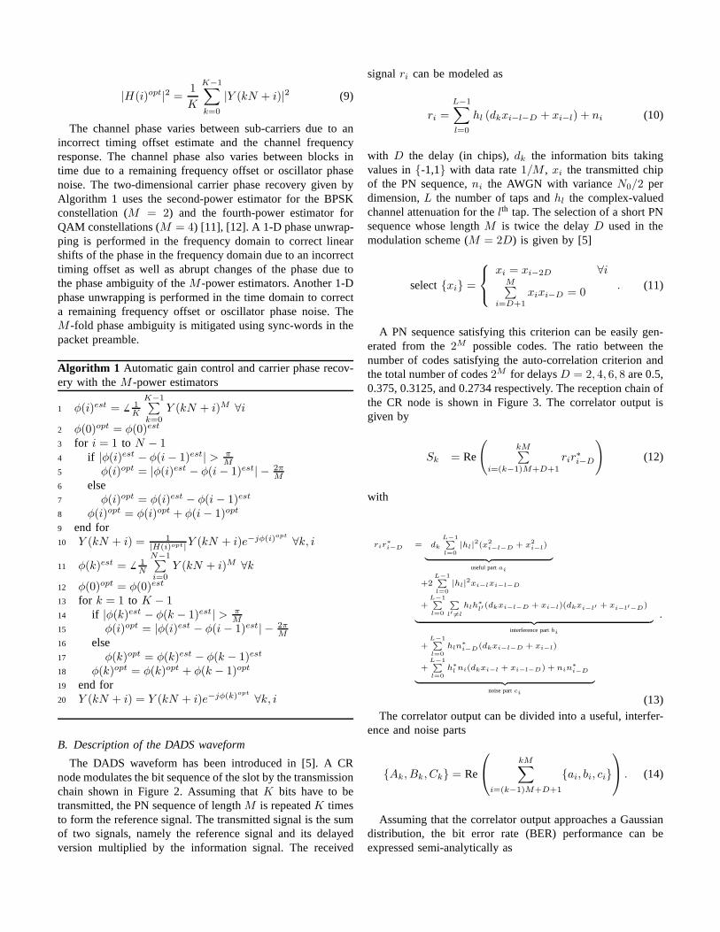
The channel phase varies between sub-carriers due to anincorrect timing offset estimate and the channel frequencyresponse. The channel phase also varies between blocks intime due to a remaining frequency offset or oscillator phasenoise. The two-dimensional carrier phase recovery given byAlgorithm 1 uses the second-power estimator for the BPSKconstellation (M = 2) and the fourth-power estimator forQAM constellations (M = 4) [11], [12]. A 1-D phase unwrap-ping is performed in the frequency domain to correct linearshifts of the phase in the frequency domain due to an incorrecttiming offset as well as abrupt changes of the phase due tothe phase ambiguity of theM -power estimators. Another 1-Dphase unwrapping is performed in the time domain to correcta remaining frequency offset or oscillator phase noise. TheM -fold phase ambiguity is mitigated using sync-words in thepacket preamble.
Algorithm 1 Automatic gain control and carrier phase recov-ery with theM -power estimators
1 φ(i)est = 6 1K
K−1∑
k=0
Y (kN + i)M ∀i
2 φ(0)opt = φ(0)est
3 for i = 1 to N − 14 if |φ(i)est − φ(i − 1)est| > π
M
5 φ(i)opt = |φ(i)est − φ(i − 1)est| − 2πM
6 else7 φ(i)opt = φ(i)est − φ(i − 1)est
8 φ(i)opt = φ(i)opt + φ(i − 1)opt
9 end for10 Y (kN + i) = 1
|H(i)opt|Y (kN + i)e−jφ(i)opt
∀k, i
11 φ(k)est = 6 1N
N−1∑
i=0
Y (kN + i)M ∀k
12 φ(0)opt = φ(0)est
13 for k = 1 to K − 114 if |φ(k)est − φ(k − 1)est| > π
M
15 φ(i)opt = |φ(i)est − φ(i − 1)est| − 2πM
16 else17 φ(k)opt = φ(k)est − φ(k − 1)est
18 φ(k)opt = φ(k)opt + φ(k − 1)opt
19 end for20 Y (kN + i) = Y (kN + i)e−jφ(k)opt
∀k, i
B. Description of the DADS waveform
The DADS waveform has been introduced in [5]. A CRnode modulates the bit sequence of the slot by the transmissionchain shown in Figure 2. Assuming thatK bits have to betransmitted, the PN sequence of lengthM is repeatedK timesto form the reference signal. The transmitted signal is the sumof two signals, namely the reference signal and its delayedversion multiplied by the information signal. The received
signalri can be modeled as
ri =
L−1∑
l=0
hl (dkxi−l−D + xi−l) + ni (10)
with D the delay (in chips),dk the information bits takingvalues in{-1,1} with data rate1/M , xi the transmitted chipof the PN sequence,ni the AWGN with varianceN0/2 perdimension,L the number of taps andhl the complex-valuedchannel attenuation for thelth tap. The selection of a short PNsequence whose lengthM is twice the delayD used in themodulation scheme (M = 2D) is given by [5]
select{xi} =
xi = xi−2D ∀iM∑
i=D+1
xixi−D = 0. (11)
A PN sequence satisfying this criterion can be easily gen-erated from the2M possible codes. The ratio between thenumber of codes satisfying the auto-correlation criterionandthe total number of codes2M for delaysD = 2, 4, 6, 8 are 0.5,0.375, 0.3125, and 0.2734 respectively. The reception chain ofthe CR node is shown in Figure 3. The correlator output isgiven by
Sk = Re
(
kM∑
i=(k−1)M+D+1
rir∗i−D
)
(12)
with
rir∗i−D = dk
L−1P
l=0
|hl|2(x2
i−l−D + x2i−l)
| {z }
useful partai
+2L−1P
l=0
|hl|2xi−lxi−l−D
+L−1P
l=0
P
l′ 6=l
hlh∗l′
(dkxi−l−D + xi−l)(dkxi−l′ + xi−l′−D)
| {z }
interference partbi
+L−1P
l=0
hln∗i−D(dkxi−l−D + xi−l)
+L−1P
l=0
h∗l ni(dkxi−l + xi−l−D) + nin
∗i−D
| {z }
noise partci
.
(13)The correlator output can be divided into a useful, interfer-
ence and noise parts
{Ak, Bk, Ck} = Re
kM∑
i=(k−1)M+D+1
{ai, bi, ci}
. (14)
Assuming that the correlator output approaches a Gaussiandistribution, the bit error rate (BER) performance can beexpressed semi-analytically as

x1 x2 . . . xM
Copy 1 Copy 2 . . . Copy K
Delay−D ×
+ Channel{PN sequence∈ [-1,1]of lengthM = 2D
withM∑
i=D+1
xixi−D = 0
Information bitsdk
(rate 1/M)
xi
xi−D
ri
Fig. 2. Transmission chain of the DADS modulation scheme with theselection of a short PN sequence
Delay−D ()∗
× Re(∑
M
rir∗
i−D) Threshold
detectorRecovered
bits d̂k
ri
r∗i−D
Sk
Fig. 3. Reception chain of the DADS modulation scheme
BER =1
2Ehl
[
Prob(Sk < 0|dk = +1)
+Prob(Sk ≥ 0|dk = −1)
]
=1
4Ehl
[
erfc
(
E[Sk|dk = +1]√
2(var[Sk|dk = +1])
)
+1
4erfc
(
− E[Sk|dk = −1]√
2(var[Sk|dk = −1])
)]
(15)
with erfc(.) the complementary error function.Ak and Bk
are deterministic values. For largeM , the correlator outputapproaches a Gaussian distribution with mean and variance
E[Sk] = Ak + E[Bk] + E[Ck]var[Sk] = var[Bk] + var[Ck]
(16)
The integrated useful partAk, interference partBk and themean of the noise partCk are given by
Ak = 2dk
L−1∑
l=0
|hl|2(M − D)Ps
E[Bk] = 0E[Ck] = 0
(17)
with Ps the energy per chip and the variance of theinterference partBk and the variance of the noise partCk
are given by
var[Bk] = 4L−1∑
l=0
|hl|4(M − D)P 2
s
+4L−1∑
l=0
∑
l′ 6=l
|hl|2|hl′ |
2(M − D)P 2s
var[Ck] = 4L−1∑
l=0
|hl|2(M − D)Ps
N0
2 + (M − D)N2
0
2
.
(18)Knowing that a transmitted data bit is the sum of two
sequences of lengthM , the energy per bitEb can be written
Fig. 4. Locations of the USRPs for the CR testbed
Fig. 5. Power switch for a USRP based on Arduino UNO and Tinkekit relaymodules
as Eb = 2MPs, the derivation of the BER formula leads tothe following expression [5]
BER =1
2Ehl
[
erfc
(
√
√
√
√
√
M−DM
L−1∑
l=0
|hl|2Eb
2N0Γ
)]
(19)
with
Γ = 1+
L−1∑
l=0
|hl|4Eb
L−1∑
l=0
|hl|2MN0
+MN0
2L−1∑
l=0
|hl|2Eb
+
L−1∑
l=0
∑
l′ 6=l
|hl|2|hl′ |
2Eb
L−1∑
l=0
|hl|2MN0
.
(20)
III. D ESCRIPTION OF THECR TESTBED AND RESULTS
The aim of the CR testbed is to develop a CR network whichcan autoconfigure and autonomously change its parametersin a realistic environment (NLOS with multipath). For thetestbed, 4 USRP B100 and 1 USRP N210 along with WBXdaughterboard (50-2200MHz) have been distributed at ourfacilities in RMA (Figure 4).
In order to remotely switch on/off USRPs, a web serverwith power switches has been developed based on ArduinoUNO and Tinkerkit relay modules (Figure 5). The Arduinoand the USRP are connected to the PC by USB cables. Therelay module is controlled and powered by the Arduino.

Fig. 6. Parameters chosen for the multichannel DAA-OFDM andDADSwaveforms
The parameters chosen for the multichannel DAA-OFDMand DADS waveforms are given in Figure 6.
Figure 7 shows the simulated BER performance of themultichannel DAA-OFDM waveform and the DADS wave-form in AWGN channels and 1-tap Rayleigh channels. Onecan observe that the multichannel DAA-OFDM waveform hasbetter BER performance than the DADS waveform by 4 dBat BER .
Figure 8 shows the setup for the scenario. In this scenario, ajammer perturbs the data transmission between two CR nodes.The first CR node has a quad-core [email protected] GHz with 8 GBRAM and the second CR node has a quad-core CPU @2.4GHz with 4 GB RAM.
The CR nodes operate at 433.92 MHz. The CR nodescan use either the multichannel DAA-OFDM waveform orthe DADS waveform in a TDD mode. Figure 9 shows thespectrogram of the CR nodes when a jammer perturbs thedata transmission. At the beginning of the demonstration, the
Fig. 7. BER performance of the TDD-OFDMA and TDD-DADS waveforms
Fig. 8. Setup used for the demonstrator
CR nodes use the DADS waveform. At a certain moment, asweeping jammer perturbs the transmission and the throughputof both users drops. When the user throughput drops undera particular threshold (1 kbps), the CR nodes switch fromthe DADS waveform to the multichannel DAA-OFDM wave-form automatically while maintaining communication. Themultichannel DAA-OFDM waveform adjusts dynamically thechannel used for transmission and mitigates interference bysensing its operational electromagnetic environment. There-fore, whenever the jammer perturbs the channel used fortransmission, the multichannel DAA-OFDM waveform is ableto jump to another channel while maintaining communication.
In the case of reactive jammers, frequency hopping canbe enabled by a predefined hopping sequence only knownto the CR nodes. The USRP RF frontend allows to performfrequency hopping over a large frequency range from 70 MHzto 6 GHz. Some tests with the USRP have shown that themaximum frequency tuning time is about 700 ns, giving amaximum limit on the hop rate of 1500 hops/s.
During measurements of the multichannel DAA-OFDM andthe DADS waveforms in a TDD mode, we have observed
Fig. 9. Spectrogram showing the cognitive capability of theCR nodes

that the averaged throughput corresponds to the maximumthroughput 250 kbps for the DADS waveform when streamingeither from the first CR node to the second CR node orfrom the second CR node to the first CR node. However,the averaged throughput for the multichannel DAA-OFDMwaveform is less than the maximum throughput 324.87 kbpsfrom the first CR node to the second CR node (64 kbps) andfrom the second CR node to the first CR node(160 kbps). Thedifference between the maximum throughput and the averagedthroughput can be explained by three factors. The first factor isthe processing power of the CR nodes. The second factor is thelarger complexity of the receivers compared to the transmitters.The third factor is the larger complexity of the multichannelDAA-OFDM waveform compared to the DADS waveform.Due to these three factors, the two CR nodes are not ableto process every packet in 252.16 ms. At the transmit side,the same packet can be sent for several frame periods. Atthe receive side, some packets can be missed. Therefore, thecomplexity of CR waveforms is a very important issue whenthey are implemented on SDR platforms especially when usinggeneral purpose processors (GPP).
Figure 10 shows some throughput results for the multichan-nel DAA-OFDM and DADS waveforms when consideringdifferent sampling rates in a FDD mode. One can observethat the averaged throughput of the DADS waveform is closeto the maximum throughput for any sampling rate. Thereis a small decrease in averaged throughput compared to themaximum throughput because the two CR nodes are not ableto process every packet in 126.08 ms. This small decrease doesnot appear in a TDD mode (averaged throughput=maximumthroughput) because the processing thread has enough timeto process every packet in 252.16 ms. For high samplingrates, the averaged throughput of the multichannel DAA-OFDM waveform is lower than the maximum throughput.However, for lower sampling rates, the difference between theaveraged throughput and the maximum throughput decreases.Therefore, more complex waveforms such as the multichannelDAA-OFDM waveform can still be used using GPP either atlower sampling rates or by defining a frame with multiple slotperiods such as in a TDD mode or in a time division multipleaccess (TDMA) to increase the time in which the packet canbe processed.
Fig. 10. Throughput results for the multichannel DAA-OFDM and DADSwaveforms
IV. CONCLUSION
This paper has provided a description of a CR testbed basedon USRP platforms and the CogWave framework with its twowaveforms, i.e. the multichannel DAA-OFDM waveform andthe DADS waveform. CogWave is an open-source softwareframework aiming at developing cognitive radio (CR) wave-forms. CogWave provides the means to implement differentCR waveforms and to develop rules to switch between dif-ferent CR waveforms during run-time according to the userneeds and the electromagnetic environment. For a scenarioin which a jammer perturbs the data transmission betweentwo CR nodes, it has been shown that when the throughputdrops under a predefined threshold, the CR nodes switchfrom the DADS waveform to the multichannel DAA-OFDMwaveform automatically while maintaining communication.Due to the low complexity of the DADS waveform, theaveraged throughput is close to the maximum throughput forsampling rates up to 2 Msps. For more complex waveformssuch as the multichannel DAA-OFDM waveform, the averagedthroughput is close to the maximum throughput at lowersampling rates (0.25 Msps). Therefore, the parameters of CRwaveforms should be properly adjusted to take into accountthe processing time vs the acquisition time when implementedon SDR platforms especially when using general purposeprocessors (GPP).
REFERENCES
[1] J. Mitola III, “Software radios: Survey, critical evaluation and futuredirections,” IEEE Aerospace and Electronic Systems Magazine, vol. 8,no. 4, pp. 25–36, Apr. 1993.
[2] ——, “Cognitive radio: making software radios more personal,” IEEEPersonal Communications, vol. 6, no. 4, pp. 13–18, Aug. 1999.
[3] “Cogwave: Open-source software framework for cognitive radio wave-forms.” [Online]. Available: https://github.com/vlenircissrma/CogWave
[4] V. Le Nir and B. Scheers, “Implementation of an adaptive OFDMAPHY/MAC on USRP platforms for a cognitive tactical radio net-work,” in Military Communications and Information Systems Conference(MCC’2012), Gdansk, Poland, Oct. 2012.
[5] ——, “DADS with short spreading sequences for high data rate commu-nications or improved BER performance,” inMilitary Communicationsand Information Systems Conference (MCC’2013), Saint-Malo, France,Oct. 2013.
[6] “Gnu radio.” [Online]. Available: http://www.gnuradio.org[7] “Omnet++ network simulation framework.” [Online]. Available:
http://www.omnetpp.org[8] “Network simulator ns-3.” [Online]. Available: http://www.nsnam.org/[9] D. Danev, E. Axell, and E. G. Larsson, “Spectrum sensing methods
for detection of DVB-T signals in AWGN and fading channels,”inProceedings of the IEEE 21st International Symposium on PersonalIndoor and Mobile Radio Communications (PIMRC’2010, Istanbul,Turkey, Sep. 2010.
[10] J.-J. van de Beek, M. Sandell, and P. O. Borjesson, “ML Estimation ofTime and Frequency Offset in OFDM Systems,”IEEE Transactions onSignal Processing, vol. 45, no. 7, pp. 1800–1805, Jul. 1997.
[11] C. N. Georghiades, “Blind Carrier Phase Acquisition for QAM constel-lations,” IEEE Transactions on Communications, vol. 45, no. 11, pp.1477–1486, Nov. 1997.
[12] H. Meyr, M. Moeneclaey, and S. A. Fechtel, Eds.,Digital Commu-nications Receivers: Synchronization, Channel Estimation, and SignalProcessing. John Wiley and Sons, 1998.