Embed Size (px)
Citation preview

Abstract—In this paper a new mechanism for the conversion
of reciprocating motion into rotary motion and vice versa is
described and analyzed. In this analysis the new type of
mechanism is applied in a reciprocating pump application. It is
found that the mechanism significantly reduces unfavorable
radial forces which subsequently result in a more efficient
motion conversion. Also, evaluation of the mechanism’s
geometry leads to the conclusion that this mechanism is better
able to withstand heavy shock loads compared to existing
mechanisms for the conversion of reciprocating motion into
rotational motion. In addition, various configurations of the
mechanism are described.
Index Terms—Motion conversion, reciprocating pumps,
crankshaft, energy efficiency.
I. INTRODUCTION
HE conversion of reciprocating motion into rotary
motion in heavy-loaded reciprocating pumps is currently
performed by a crankshaft or an eccentric mechanism.
Although these mechanisms performed well during recent
decades, increasing mechanical problems arise due to the
increasing pressure and displacement requirements partly
accelerated by the shale gas revolution[1].
In a response to these increasing demands for pumps that
are able to withstand extreme pressures, pump manufacturers
straightforwardly increase their crankshafts in size which
results in excessively large and heavy mechanisms which
remain sensitive to mechanical (fatigue) failures due to two
fundamental weaknesses.
The first key weakness is the occurrence of critical stress
concentrations anywhere a change in diameter exists. These
stress concentrations are prone to fatigue failures, especially
under high shock loadings such as takes place in reciprocating
pumps and combustion engines[2]. The second weakness in
the current mechanisms is the limited allowable wrist pin
bearing load. This is caused by the limited space available for
increasing bearing size and because this bearing is difficult to
lubricate.
These two key weaknesses jointly restrict the maximum
allowable load on the crankshaft mechanism. A modular
eccentric mechanism suffers only from the limited wrist pin
bearing load. A new motion conversion mechanism which is
commercially known as the “Efficient Motion Converter”
(also “EMC”) doesn’t have these weaknesses and should be
able to withstand heavy shock loads. In this paper the
Manuscript received February 17, 2014; revised March 25, 2014. J.H.
Sol is MD with Sol Beheer B.V., Haringhuizen, 1769HD, the
Netherlands. e-mail: [email protected].
mechanism is presented and initial analyses are performed.
II. DESCRIPTION OF MECHANISM
A. Core components & motion
Although the new mechanism also consists out of a
(modular) eccentric, the rest of the mechanism is completely
different. An exploded view drawing of the mechanism is
given in Fig. 1.
The core of the mechanism consists out of a modular
eccentric which is mounted on a splined shaft (#1). The
eccentric movement of the eccentric sheave (#2) is not
transferred through a connection rod as usually, instead, this
movement is transferred via a bearing (4#) to a bearing
housing (#3) to two rods (#6). The other outer side of the
hinging rods are connected to a reciprocating member (#5)
which moves in a pure reciprocating way. On one end of the
reciprocating member, or at both ends, a crosshead (#11) or
other components can be connected which require to move in a reciprocating way. An illustration of the movement from
top dead center to bottom dead center is given in Fig. 2.
Description and Analysis of New Motion
Conversion Mechanism for Heavy-Loaded
Reciprocating Pumps
J. H. Sol, Member, IAENG
T
Fig. 1. Exploded view of the mechanism. Although the mechanism also
consists out of a commonly used (modular) eccentric, various new components
are introduced.
Proceedings of the World Congress on Engineering 2014 Vol II, WCE 2014, July 2 - 4, 2014, London, U.K.
ISBN: 978-988-19253-5-0 ISSN: 2078-0958 (Print); ISSN: 2078-0966 (Online)
WCE 2014

Fig. 2. Movement of the mechanism from top dead center to bottom dead
center. The shaft rotates counter clockwise.
III. ANALYSIS OF MECHANISM
A. Force analysis
In order to determine how the load is being transferred
along the various components, a static state force analysis is
performed. A crosshead load of 100 N is applied (being in the
– Z direction) at a variety of shaft positions. In this analysis
the shaft(#1) and the linear ball bearing (#13) were both fixed
for rotation and translation. In Fig. 3 the various nodes are
illustrated and in Fig. 4 the relevant dimensions are
illustrated.
Fig. 3. Definition of contacts. Part numbers refer to figure 1.
From this analysis it is found that the reaction force in Y-
direction on the crosshead (i.e. node 1) is far lower compared
to the radial force induced by a crankshaft or eccentric
mechanism. To illustrate, in a crank with a commonly used
r/s ratio of 2.5 the maximum radial load on the crosshead is
more than 20% of the plunger load. In the new mechanism
the maximum radial load is 10.5% of the plunger load. This
is caused by the fact that the two connection rods (#6) which
jointly transfer the plunger load to the bearing housing are
pointing in opposite direction. Therefore the Y-forces of both
rods cancel each other to a large extent out.
All relative values can be found in Table IV in APPENDIX I.
Fig. 4. Relevant dimensions for force and motion analysis.
B. Motion analysis
Motion analysis is performed on the new mechanism and
compared with motion plots of a crank mechanism with a
similar stroke (50.8 mm) and with a r/s ratio of 2.5. For the
new mechanism the same geometry is used as in the force
analysis.
Displacement, velocity and acceleration plots for both
mechanisms are illustrated in Fig. 5., Fig. 6. and Fig 7. respectively. Measurements are done on top of the crosshead.
Fig. 5. Displacement plots of new mechanism, being the continuous curve,
and conventional crank mechanism, being the dotted curve.
Fig. 6. Velocity plots of new mechanism, being the continuous curve, and
conventional crank mechanism, being the dotted curve.
Proceedings of the World Congress on Engineering 2014 Vol II, WCE 2014, July 2 - 4, 2014, London, U.K.
ISBN: 978-988-19253-5-0 ISSN: 2078-0958 (Print); ISSN: 2078-0966 (Online)
WCE 2014

Fig. 7. Acceleration plots of new mechanism, being the continuous curve,
and conventional crank mechanism, being the dotted curve.
In the motion plots the crosshead starts at bottom dead center and one cycle is completed at 1 sec..
It is found that there are significant differences in
displacement, velocity and acceleration curves between the
new mechanism and the crankshaft mechanism. From a
reciprocating pump perspective especially the difference in
acceleration is interesting as pump’s maximum rotational
frequency, and thereby are also pump’s displacement, is
partly restricted by plunger acceleration due to potential
cavitation during the inlet phase. As the alternative
mechanism has a significant lower acceleration (in this case
15,4% lower) during top dead center, risk of cavitation is
significantly reduced at the same rotational frequency.
C. Analytical mechanical strength considerations
Although no FEA analyses are performed yet, initial
analytical evaluations gain insight into the relative
mechanical strength of the mechanism. Three observations
regarding mechanical strength are of interest. The first observation is related to the wrist pin bearing. Normally the
wrist pin bearing is the highest loaded bearing in a crankshaft
/ eccentric mechanism which is mainly caused by the limited
available space for this bearing. The highest loaded bearings
in the alternative mechanism are part #7 and part #8. These
bearings are not restricted by available space and can
therefore be chosen until a certain load level is achieved.
Secondly, no critical change in diameters exist. In a crank
various diameter changes exist in which stresses concentrate
and which are prone to fatigue failures. The new mechanism
doesn’t have these stress inducing fillets and should therefore
be better suited for high shock loadings. The third observation is specifically related to triplex pumps which consist out of a
cast crank which is supported at both ends. The modularity of
the new mechanism allows for adding main bearings between
the eccentric webs which results in a great reduction in
bending moment. Secondly, a straight shaft as applied in the
EMC has a higher torsional rigidness than a crank with webs
which subsequently results in lower torsional stresses.
D. Conversion efficiency analysis
The mechanical efficiency of the mechanism under
investigation can be determined by the identification and
calculation of friction losses caused by the bearings. In this
analysis it is assumed that throughout the whole cycle a
constant load is applied on the top of the plunger.
The total amount of work required to overcome the friction
losses can be calculated with the following equation:
WTotalFriction = WNode 1 + 2WNode 2 + 2WNode 3 +WNode 4 + WNode 5 + WNode 6 + 2WNode 7 (1)
Node 1 consists of a linear ball bearing of which the friction
work can be calculated as follows:
𝑊𝑁𝑜𝑑𝑒 1 = 𝐹𝑓1𝑎𝑣 ∗ ∆𝑥1 (2)
Herein represents Δx1 the relative translation between the
crosshead and the linear ball bearing, which is equal to 2s.
𝐹𝑓1𝑎𝑣 represents the average friction force between the
crosshead and the linear ball bearing during one cycle. This
average friction force can be calculated with the following
formula:
𝐹𝑓1𝑎𝑣 = 𝐹𝑟𝑒𝑠1𝑎𝑣 ∗ 𝜇𝑙𝑏𝑏 (3)
𝐹𝑟𝑒𝑠1𝑎𝑣 can be calculated by integrating the trend line of the
force plot of the resultant force of node 1. 𝜇𝑙𝑏𝑏 represents the
friction coefficient a linear ball bearing. Substituting (3) in
(2) and replacing ∆𝑥1 by 2s results in:
𝑊𝑁𝑜𝑑𝑒 1 = 𝐹𝑟𝑒𝑠1𝑎𝑣 ∗ 𝜇𝑙𝑏𝑏 ∗ 2𝑠 (4)
Node 2 represents an oscillating needle bearing with a limited rotation angle. Friction work can be calculated by using the
following equation:
𝑊𝑁𝑜𝑑𝑒 2 = 𝐹𝑓2𝑎𝑣 ∗ ∆𝑥2 (5)
Herein Δx2 represents the relative movement between the
inner and the outer ring of the bearing while 𝐹𝑓2𝑎𝑣 represents
the average friction force during one cycle. Δx2 can be calculated with the following equation:
𝛥𝑥2 = 𝜋 ∗ 𝑑2 ∗2∗𝜃2
360 (6)
𝜃2 represents the angular displacement of the rod (part #6)
relative to the reciprocating member (part #5) in the XZ plane (coordinate system of Fig. 3) during one cycle. As the rod
starts in horizontal position, during one main shaft rotation
the total angular displacement is equal to 2*θ2. d2 represents
the mean diameter of the needle bearing.
Due to the relative constancy along the cycle 𝐹𝑓2𝑎𝑣 can be
calculated by taking the average of the resultant force of node
2 during one cycle and multiply this figure with the friction
coefficient of a needle bearing.
Substitution of (6) into (5) and replacement of 𝐹𝑓2𝑎𝑣 by
𝐹𝑟𝑒𝑠2𝑎𝑣 results in:
𝑊𝑁𝑜𝑑𝑒 2 = 𝐹𝑟𝑒𝑠2𝑎𝑣 ∗ 𝜇𝑛𝑏 ∗ 𝜋 ∗ 𝑑2 ∗2∗𝜃2
360 (7)
The friction losses of node 3, 4, 5 can be determined in a
similar way as described for node 2.
The work required to overcome friction per cycle for node 6
can be calculated by:
𝑊𝑁𝑜𝑑𝑒 6 = 𝐹𝑓6𝑎𝑣 ∗ 𝜋 ∗ 𝑑6 = 𝐹𝑟𝑒𝑠6𝑎𝑣 ∗ 𝜇𝑛𝑏 ∗ 𝜋 ∗ 𝑑6 (8)
𝐹𝑟𝑒𝑠6𝑎𝑣 represents the average resultant force on node 6, 𝜇𝑛𝑏
represents the friction coefficient of a needle bearing and 𝑑6 represents the average diameter of the needle bearing (part #
4). WNode 7 can be calculated in the same way by adjusting the
Proceedings of the World Congress on Engineering 2014 Vol II, WCE 2014, July 2 - 4, 2014, London, U.K.
ISBN: 978-988-19253-5-0 ISSN: 2078-0958 (Print); ISSN: 2078-0966 (Online)
WCE 2014
formula for the specific diameter, load and bearing
specifications of node 7.
Combining equations (4), (7), (8) and rewriting these
equations for similar nodes allows for replacing equation (1)
by the following:
𝑊𝑇𝑜𝑡𝑎𝑙𝐹𝑟𝑖𝑐𝑡𝑖𝑜𝑛 = (𝐹𝑟𝑒𝑠1𝑎𝑣 ∗ 𝜇𝑙𝑏𝑏 ∗ 2𝑠) + 2(𝐹𝑟𝑒𝑠2𝑎𝑣 ∗ 𝜇𝑛𝑏 ∗
𝜋 ∗ 𝑑2 ∗2∗𝜃2
360) + 2(𝐹𝑟𝑒𝑠3𝑎𝑣 ∗ 𝜇𝑛𝑏 ∗ 𝜋 ∗ 𝑑3 ∗
2∗𝜃3
360) +
(𝐹𝑟𝑒𝑠4𝑎𝑣 ∗ 𝜇𝑛𝑏 ∗ 𝜋 ∗ 𝑑4 ∗2∗𝜃4
360) + (𝐹𝑟𝑒𝑠5𝑎𝑣 ∗ 𝜇𝑛𝑏 ∗ 𝜋 ∗ 𝑑5 ∗
2∗𝜃5
360) + (𝐹𝑟𝑒𝑠6𝑎𝑣 ∗ 𝜇𝑛𝑏 ∗ 𝜋 ∗ 𝑑6) + 2(𝐹𝑟𝑒𝑠7𝑎𝑣 ∗ 𝜇𝑠𝑏 ∗ 𝜋 ∗ 𝑑7)
(9)
This represents the total amount of work to overcome mechanical friction during one cycle. In order to calculate the
mechanical efficiency of the mechanism this amount of
friction work has to be compared with the total amount of
work input during one cycle with a given load. This will be
demonstrated in the following calculation example.
Calculation example
TABLE II
VALUES VARIABLES
Variable Value Variable Value
Fplunger 20 kN d5 22.5 mm
s 50.8 mm d6 115 mm
θ2, θ3, θ4, θ5 19.5° d7 76.5 mm
d2 23 mm μlbb 0.0025
d3 23 mm μnb 0.003
d4 22.5 mm μsb 0.0018
Before equation (9) can be applied the average loads on the
various nodes have to be determined. For node 2, 3, 4, 5, 6, 7
this can be done straightforwardly by calculating the
arithmetic mean of the various values of the various positions
from Table IV. In order to determine the average load for
node 1 the resultant force (for 0°-180° and for 180°-360° separately) have to be plotted where after a trend line can be
added.
Fig. 8. Resultant force plot from 0° to 180° shaft angle at node 1, being the
crosshead. 0°corresponds with top dead center plunger position. 4th order
polynomial function is fitted as trend line.
Average resultant force from 0° to 180° is found by
integrating the trend line function and dividing this definite
integral value through 180.
𝐹𝑟𝑒𝑠1𝑎𝑣0°−180° =1
180 − 0∫ (2 ∗ 10−8𝑥4 − 0.00001𝑥3
180
0
+ 0.0006𝑥2 + 0.0844𝑥 + 0.2569)𝑑𝑥
𝐹𝑟𝑒𝑠1𝑎𝑣0°−180° = 4.61 [%]
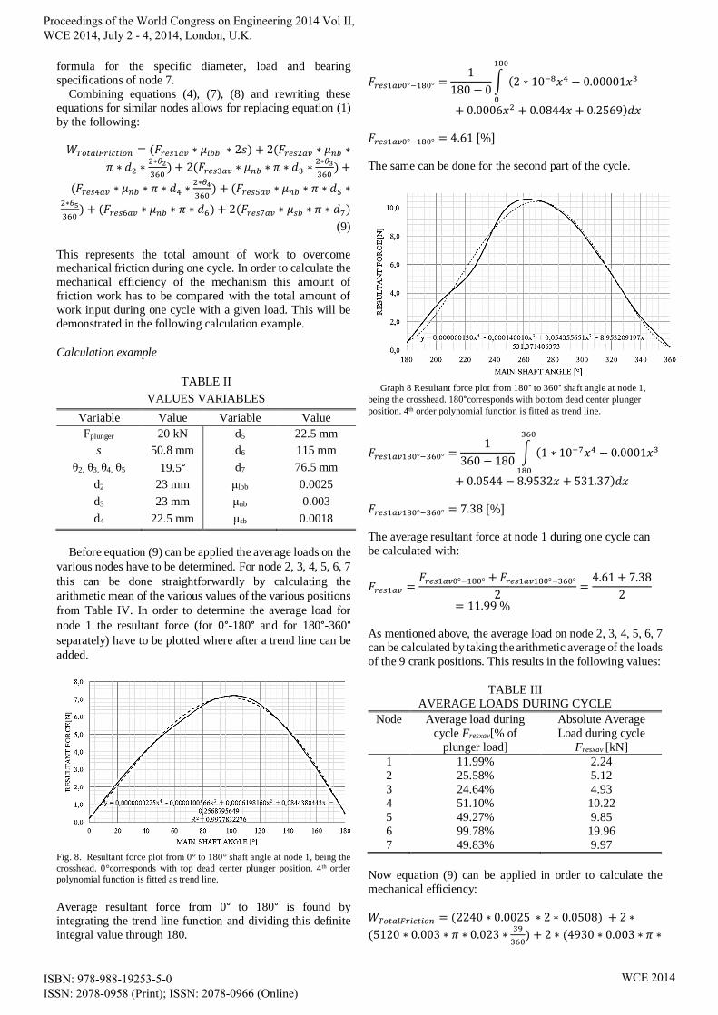
The same can be done for the second part of the cycle.
Graph 8 Resultant force plot from 180° to 360° shaft angle at node 1,
being the crosshead. 180°corresponds with bottom dead center plunger
position. 4th order polynomial function is fitted as trend line.
𝐹𝑟𝑒𝑠1𝑎𝑣180°−360° =1
360 − 180∫ (1 ∗ 10−7𝑥4 − 0.0001𝑥3
360
180
+ 0.0544 − 8.9532𝑥 + 531.37)𝑑𝑥
𝐹𝑟𝑒𝑠1𝑎𝑣180°−360° = 7.38 [%]
The average resultant force at node 1 during one cycle can
be calculated with:
𝐹𝑟𝑒𝑠1𝑎𝑣 =𝐹𝑟𝑒𝑠1𝑎𝑣0°−180° + 𝐹𝑟𝑒𝑠1𝑎𝑣180°−360°
2=
4.61 + 7.38
2= 11.99 %
As mentioned above, the average load on node 2, 3, 4, 5, 6, 7
can be calculated by taking the arithmetic average of the loads
of the 9 crank positions. This results in the following values:
TABLE III
AVERAGE LOADS DURING CYCLE
Node Average load during
cycle Fresxav[% of
plunger load]
Absolute Average
Load during cycle
Fresxav [kN]
1 11.99% 2.24
2 25.58% 5.12
3 24.64% 4.93
4 51.10% 10.22
5 49.27% 9.85
6 99.78% 19.96
7 49.83% 9.97
Now equation (9) can be applied in order to calculate the
mechanical efficiency:
𝑊𝑇𝑜𝑡𝑎𝑙𝐹𝑟𝑖𝑐𝑡𝑖𝑜𝑛 = (2240 ∗ 0.0025 ∗ 2 ∗ 0.0508) + 2 ∗
(5120 ∗ 0.003 ∗ 𝜋 ∗ 0.023 ∗39
360) + 2 ∗ (4930 ∗ 0.003 ∗ 𝜋 ∗
Proceedings of the World Congress on Engineering 2014 Vol II, WCE 2014, July 2 - 4, 2014, London, U.K.
ISBN: 978-988-19253-5-0 ISSN: 2078-0958 (Print); ISSN: 2078-0966 (Online)
WCE 2014

0.023 ∗39
360) + (10220 ∗ 0.003 ∗ 𝜋 ∗ 0.0225 ∗
39
360) +
(9850 ∗ 0.003 ∗ 𝜋 ∗ 0.0225 ∗39
360) + (19960 ∗ 0.003 ∗ 𝜋 ∗
0.115) + 2 ∗ (9970 ∗ 0.0018 ∗ 𝜋 ∗ 0.0765)
𝑊𝑇𝑜𝑡𝑎𝑙𝐹𝑟𝑖𝑐𝑡𝑖𝑜𝑛 = 31.74 [𝑁𝑚]
The total amount of work exerted on the plunger can be calculated with:
𝑊𝑃𝑙𝑢𝑛𝑔𝑒𝑟 = 𝐹𝑃𝑙𝑢𝑛𝑔𝑒𝑟 ∗ ∆𝑥 = 𝐹𝑃𝑙𝑢𝑛𝑔𝑒𝑟 ∗ 2 ∗ 𝑠
= 20000 ∗ 2 ∗ 0.0508 = 2032 [𝑁𝑚]
The mechanical efficiency of the mechanism can
subsequently be determined by:
𝜂𝑚𝑒𝑐ℎ𝑎𝑛𝑖𝑠𝑚 = 𝑊𝑃𝑙𝑢𝑛𝑔𝑒𝑟 − 𝑊𝑇𝑜𝑡𝑎𝑙𝐹𝑟𝑖𝑐𝑡𝑖𝑜𝑛
𝑊𝑃𝑙𝑢𝑛𝑔𝑒𝑟
=2032 − 31.74
2032
= 98.44 [%]
In order to bring this number in perspective the efficiencies
of a crank mechanism and eccentric mechanism are
calculated as well. Using the same methodology and case data
it is found that a normal crankshaft mechanism has a
theoretical mechanical efficiency of 98.04% and an eccentric
97.38%. This means the EMC mechanism is 0.4% more
efficient than a crank mechanism and 1.06% more efficient
than an eccentric mechanism.
The efficiency gain can, for the greater part, be attributed
to the lower frictional losses in the crosshead. This is caused
by the lower normal force on the crosshead as well as the
decreased friction coefficient (0.07(-) vs. 0.0025(-)) due to
the introduction of the linear ball bearing instead of a normal
crosshead configuration.
Please also note that these calculations do not take into
account deformations due to the mechanical loads. This
causes unfavorable misalignments which induce additional
friction. It’s likely that this is higher with a normal crankshaft
than with the EMC as the EMC mechanism is a far more rigid
mechanism.
IV. CONFIGURATIONS
A. Single configuration
The single configuration can be used for triplex pumps by
placing three mechanisms in-line on the same main shaft. In
this configuration four instead of two main bearings can be
applied. This results in a significant reduction in bending
moment and allows for a higher plunger load.
B. Boxer configuration
The boxer configuration allows for plunger installation at
both ends of the mechanism. By doing this displacement or
pressure capabilities can be doubled. Sideway forces can be
absorbed at one side of the mechanism by installing a linear
ball bearing while at the other side a pony rod can be installed
directly. An illustration of this mechanism is given in Fig. 9.
C. Combination combustion cycle – pump cycle
Another possible configuration is to use the mechanism in
a dual role between combustion engine and pump. This dual
role entails that at one side of the mechanism work is being
added by an internal combustion engine cycle while at the
other side of the mechanism work is being retracted by a
reciprocating pump configuration. In this configuration the
forces induced by the combustion are directly being
transferred to the plunger that is being used for pump
purposes and therefore a minimal residual force is being
transferred to the oscillating and rotating members.
Fig. 9. New mechanism configured as boxer configuration.
This configuration brings along a variety of advantages.
Firstly, the (residual) forces on the bearings are strongly reduced which leads to lower friction losses and a higher
reliability. Secondly, no drive motor and transmission is
required anymore which further increases efficiency,
reliability and also simplicity. Thirdly, total system size and
weight can be reduced significantly.
Fig. 10. New mechanism allows for a dual role between combustion cycle
and pump cycle.
General considerations on combined configuration
For this first evaluation ideal conditions and processes are
assumed. A first requirement for this configuration is that the
amount of work that is retracted by the pump has to be equal to the amount of work that is added by the combustion cycle.
This can be written as:
∑ W = Wnet_combustion − Wpump = 0 (10)
In combustion engine terminology the average effective
pressure over one cycle is known as I.M.E.P. (Indicated Mean
Effective Pressure). A typical IMEP value for a boosted two-
stroke gasoline engine is about 15 bar [3]. This means that in
case an equal stroke and plunger diameter for both sides is
used, plunger pressure is limited to 15 bar. However, pump
plunger and combustion piston size don’t have to be the same;
the combustion piston can have a (far) greater surface than
Proceedings of the World Congress on Engineering 2014 Vol II, WCE 2014, July 2 - 4, 2014, London, U.K.
ISBN: 978-988-19253-5-0 ISSN: 2078-0958 (Print); ISSN: 2078-0966 (Online)
WCE 2014
the plunger diameter. For example, if the plunger diameter is
decreased 1.5 times and the combustion piston is increased
1.5 times the plunger pressure can be increased up to 76 bar.
There are however limitations to the extent to which the
diameters can be adjusted. Due to specific combustion engine
characteristics the ratio between bore and stroke of the combustion piston is limited to about 2 [4]. It is however
doubtful whether this limit also applies in case the new
mechanism is applied as this limit is partly caused by
mechanical limitations. As these mechanical limitations
might not apply in case the new mechanism is applied further
research should be done to investigate which bore-to-stroke
ratios are possible.
The amount of work that is delivered during the expansion
stroke, Wexpansion, should be equal to the amount of work that
is required for the pump, being Wpump, plus the amount of
work that is required for compression of the air-fuel mixture, being Wcompression. When the combustion piston travels from
top dead center to bottom dead center the first work factor,
being Wpump, is directly transferred via the reciprocating
member to the plunger while the remaining amount of work,
being Wcompression, is temporarily stored in the flywheel. When
the combustion piston travels back from the bottom dead
center to the top dead center the work stored in the flywheel
has to be transferred back in order to compress the air-fuel
mixture. This means that during the whole cycle the
mechanism is only loaded with the forces related to the air-
fuel mixture compression and not with the forces related to the pump compression. This subsequently means a significant
reduction in load on all parts which results in a higher
efficiency and allows for a lighter construction.
The most favorable configuration would include a 2-stroke
Otto cycle. A two-stroke cycle delivers one power stroke per
shaft cycle while a four-stroke deliver one power-stroke per
two shaft cycles. This means that with a four stroke cycle
lower pump pressures can be achieved and also more energy
has to be stored in the flywheel which undo the low forces
advantage. Also, an Otto cycle is preferred to a Diesel cycle.
The Otto-cycle has a far lower pressure at the end of the
compression stroke compared to a Diesel cycle. The forces resulting from compression are the highest forces in the
mechanism during the cycle and should therefore be
minimized. Consequently, an Otto cycle is preferred to a
Diesel cycle although both cycles are feasible.
V. FUTURE RESEARCH
An initial analysis is performed on the mechanism in a
reciprocating pump application. A further in-depth analysis
on strength, vibration and lubrication is required for
determining the feasibility and attractiveness of the
mechanism. Also the combined combustion configuration
deserves a further in-depth feasibility analysis. In this
analysis mainly the timings of the various forces should be
explored in more detail.
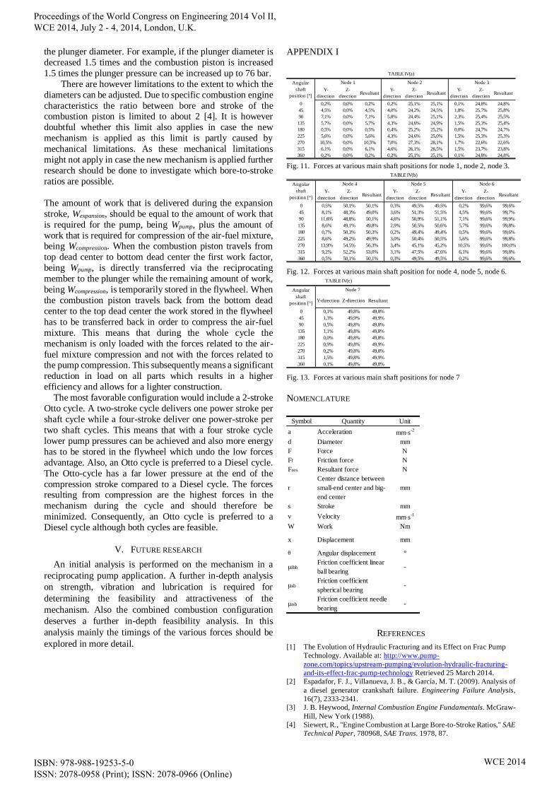
APPENDIX I
Fig. 11. Forces at various main shaft positions for node 1, node 2, node 3.
Fig. 12. Forces at various main shaft position for node 4, node 5, node 6.
Fig. 13. Forces at various main shaft positions for node 7
NOMENCLATURE
REFERENCES
[1] The Evolution of Hydraulic Fracturing and its Effect on Frac Pump
Technology. Available at: http://www.pump-
zone.com/topics/upstream-pumping/evolution-hydraulic-fracturing-
and-its-effect-frac-pump-technology Retrieved 25 March 2014.
[2] Espadafor, F. J., Villanueva, J. B., & García, M. T. (2009). Analysis of
a diesel generator crankshaft failure. Engineering Failure Analysis,
16(7), 2333-2341.
[3] J. B. Heywood, Internal Combustion Engine Fundamentals. McGraw-
Hill, New York (1988).
[4] Siewert, R., "Engine Combustion at Large Bore-to-Stroke Ratios," SAE
Technical Paper, 780968, SAE Trans. 1978, 87.
Y-
direction
Z-
directionResultant
Y-
direction
Z-
directionResultant
Y-
direction
Z-
directionResultant
0 0,2% 0,0% 0,2% 0,2% 25,1% 25,1% 0,1% 24,8% 24,8%
45 4,5% 0,0% 4,5% 4,0% 24,2% 24,5% 1,8% 25,7% 25,8%
90 7,1% 0,0% 7,1% 5,8% 24,4% 25,1% 2,3% 25,4% 25,5%
135 5,7% 0,0% 5,7% 4,3% 24,6% 24,9% 1,5% 25,3% 25,4%
180 0,5% 0,0% 0,5% 0,4% 25,2% 25,2% 0,0% 24,7% 24,7%
225 5,6% 0,0% 5,6% 4,3% 24,6% 25,0% 1,5% 25,3% 25,3%
270 10,5% 0,0% 10,5% 7,0% 27,3% 28,1% 1,7% 22,6% 22,6%
315 6,1% 0,0% 6,1% 4,6% 26,1% 26,5% 1,5% 23,7% 23,8%
360 0,2% 0,0% 0,2% 0,2% 25,1% 25,1% 0,1% 24,8% 24,8%
TABLE IV(a)
Angular
shaft
position [°]
Node 1 Node 2 Node 3
Y-
direction
Z-
directionResultant
Y-
direction
Z-
directionResultant
Y-
direction
Z-
directionResultant
0 0,5% 50,1% 50,1% 0,3% 49,5% 49,5% 0,2% 99,6% 99,6%
45 8,1% 48,3% 49,0% 3,6% 51,3% 51,5% 4,5% 99,6% 99,7%
90 11,6% 48,8% 50,1% 4,6% 50,9% 51,1% 7,1% 99,6% 99,9%
135 8,6% 49,1% 49,8% 2,9% 50,5% 50,6% 5,7% 99,6% 99,8%
180 0,7% 50,3% 50,3% 0,2% 49,4% 49,4% 0,5% 99,6% 99,6%
225 8,6% 49,2% 49,9% 3,0% 50,4% 50,5% 5,6% 99,6% 99,8%
270 13,9% 54,5% 56,3% 3,4% 45,1% 45,2% 10,5% 99,6% 100,0%
315 9,2% 52,2% 53,0% 3,1% 47,5% 47,6% 6,1% 99,6% 99,8%
360 0,5% 50,1% 50,1% 0,3% 49,5% 49,5% 0,2% 99,6% 99,6%
TABLE IV(b)
Node 6Angular
shaft
position [°]
Node 4 Node 5
Y-direction Z-direction Resultant
0 0,1% 49,8% 49,8%
45 1,3% 49,9% 49,9%
90 0,5% 49,8% 49,8%
135 1,1% 49,8% 49,8%
180 0,0% 49,8% 49,8%
225 0,9% 49,8% 49,9%
270 0,2% 49,8% 49,8%
315 1,5% 49,8% 49,9%
360 0,1% 49,8% 49,8%
Node 7
TABLE IV(c)
Angular
shaft
position [°]
Symbol Quantity Unit
a Acceleration mm·s-2
d Diameter mm
F Force N
Ff Friction force N
Fres Resultant force N
r
Center distance between
small-end center and big-
end center
mm
s Stroke mm
v Velocity mm·s-1
W Work Nm
x Displacement mm
θ Angular displacement °
μlbbFriction coefficient linear
ball bearing-
μsbFriction coefficient
spherical bearing-
μnbFriction coefficient needle
bearing-
NOMENCLATURE
Proceedings of the World Congress on Engineering 2014 Vol II, WCE 2014, July 2 - 4, 2014, London, U.K.
ISBN: 978-988-19253-5-0 ISSN: 2078-0958 (Print); ISSN: 2078-0966 (Online)
WCE 2014