Embed Size (px)
Citation preview

Publication Date: June 2009 ISBN 978-1-921602-61-0
ATSB TRANSPORT SAFETY REPORT
- 1 -
Rail Occurrence Investigation RO-2008-004 Final
Derailment of Train 1MA6Q near Pura Pura, Vic.
30 March 2008
ABSTRACT At about 19321 on 30 March 2008, freight train 1MA6Q, travelling from Melbourne to Adelaide, derailed on the Mt Emu Creek bridge near Pura Pura, Victoria. Twenty-one wagons derailed, coming to rest on the track past the bridge abutment. As a result of the derailment, some containers burst spilling their contents onto the rail corridor and the adjacent public road.
The investigation determined that the derailment occurred as a result of a failed rail due to fatigue cracking emanating from an unused bolt-hole.
FACTUAL INFORMATION Location The derailment occurred on the Defined Interstate Rail Network (DIRN) at the Mount Emu Creek bridge near Pura Pura located 192.875 km west of Melbourne and about 4 km southeast of Vite
1 The 24-hour clock is used in this report to describe the
local time of day, Eastern Daylight Tme (EDT), as particular
events occurred.
Vite crossing loop in Victoria. The DIRN at this location is managed by the Australian Rail Track Corporation (ARTC). The ARTC contract Works Infrastructure for track maintenance.
Mount Emu Creek bridge is constructed of brick piers and concrete spans with an encapsulated top (Figure 1).
Figure 1: Point of derailment on bridge
Track infrastructure The single tangent track consists of Continuous Welded Rail (CWR) 47kg/m (94lb/yd) anchored to
The Australian Transport Safety Bureau (ATSB) is an operationally independent multi-modal Bureau within the Australian Government Department of Infrastructure, Transport, Regional Development and Local Government.
The ATSB is responsible for investigating accidents and other transport safety matters involving civil aviation, marine and rail operations in Australia that fall within Commonwealth jurisdiction.
The ATSB performs its functions in accordance with the provisions of the Transport Safety Investigation Act 2003 and, where applicable, relevant international agreements.
ATSB investigations are independent of regulatory, operator or other external bodies. It is not the object of an investigation to determine blame or liability.
© Commonwealth of Australia 2009
This work is copyright. In the interests of enhancing the value of the information contained in this publication you may copy, download, display, print, reproduce and distribute this material in unaltered form (retaining this notice). However, copyright in the material obtained from non-Commonwealth agencies, private individuals or organisations, belongs to those agencies, individuals or organisations. Where you want to use their material you will need to contact them directly.
Subject to the provisions of the Copyright Act 1968, you must not make any other use of the material in this publication unless you have the permission of the Australian Transport Safety Bureau.
Please direct requests for further information or authorisation to:
Commonwealth Copyright Administration, Copyright Law Branch Attorney-General’s Department Robert Garran Offices National Circuit BARTON ACT 2600 www.ag.gov.au/cca
Australian Transport Safety Bureau PO Box 967, Civic Square ACT 2608 Australia 1800 020 616 +61 2 6257 4150 from overseas www.atsb.gov.au INFRA-08533 Released in accordance with section 25 of the Transport Safety Investigation Act 2003
Direction of travel
concrete sleepers with resilient fasteners in a bed of ballast nominally 450 mm deep.
The rail was manufactured in June 1961 to Australian Standard Specifications for Railway Permanent Way Materials, AS E22-1949 Steel Rails, the standard at that time. The track had been in-service at Pura Pura for in excess of 20 years. Originally, the track was laid in 40 ft (12.182 m) lengths and connected by a mechanical joint consisting of fish-plates and bolts. At some time around the mid-1980’s, based on the only records available, the mechanical joints were removed and the rail lengths welded together using an alumino-thermic process2 to form CWR. This process enabled the track to be less maintenance intensive. The redundant bolts holes were left in-situ and were periodically inspected for defects as specified for standard mechanical joint fish-plated track.
Track inspection and assessment
The track, in the vicinity of the derailment, is inspected and assessed according to an ARTC standard, detailed in the Track Access, Rail – Inspection and Assessment Specification, Issue 2.3, dated August 1998. This standard is used exclusively on the ARTC network in Victoria. Other areas of the ARTC network, outside Victoria, are largely inspected and assessed using the ARTC Track and Civil Code of Practice (CoP) (Table 3).
The ARTC contracted EDI Works Infrastructure (now Downer EDI Works) to maintain the track in accordance with the ARTC specifications. Continuous ultrasonic testing of that section of track is subcontracted to Speno Rail Maintenance Australia Pty Ltd (Speno) using the Track Access standard.
Train and crew information Train 1MA6Q was operated by Interail Australia (Interail). It consisted of three locomotives (EL58 leading, EL51, and RL302 trailing, leased from Chicago Freight Car Leasing Australia [CFCLA]) hauling 44 wagons (owned by Interail) with a total train length of 1,063 m and gross weight of 2,571 t. There were no dangerous goods on the train at the time of the derailment. The train crew comprised two drivers who were assessed as
2 A process of fusion welding using an exothermic reaction.
competent, medically fit for duty, and had regularly worked the corridor where the derailment occurred.
Environmental conditions The derailment occurred at about 1932. The weather was mild and overcast and the temperature at the time of the derailment was estimated to be 14°C3. The minimum and maximum temperatures for two days prior to the derailment were 6.5°C and 19°C respectively.
Occurrence On 30 March 2008, the two train drivers involved in the derailment signed on for duty at 1400 and joined train 1MA6Q at North Dynon depot in Melbourne. They completed prescribed engine, brake and safety checks before departing from Melbourne at 1615, bound for Dimboola where the crew were rostered to change. Train 1MA6Q would then continue to Adelaide.
The passage of train 1MA6Q through the Melbourne metropolitan area was uneventful. At about 1925, the train arrived at Vite Vite and waited for another train, 5PM5, to arrive into the crossing loop from the opposite direction. Train 1MA6Q then departed Vite Vite at about 1930. On departing Vite Vite, the train driver sent the required ‘depart’ signal via the Alternate Safe-working (ASW)4 unit, in the locomotive cab, to the train controller in Adelaide.
Just before Pura Pura, the train came around a curve and downhill towards the Mount Emu Creek bridge. The driver recalled that he had the throttle handle set in the 8th notch to climb the gradient on the other side of the bridge. The driver received an acknowledgement from the train controller via the ASW unit as the train passed over the bridge. The driver glanced at the speedometer and recalled an indicated speed of about 95 km/h. At this time both drivers heard an ‘enormous bang’ and noticed the locomotive bounce. The driver said to the co-driver ‘I wonder what that was.’ The co-driver then noticed what appeared to be smoke in the rear vision mirror. The driver looked in the rear vision mirror and commented that it was not
3 The estimate of temperature is based on the recorded
temperatures at Westmere about 15km WNW of the site.
4 A form of electronic authority system.
- 2 -
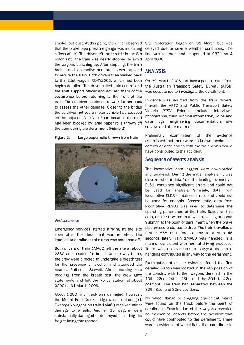
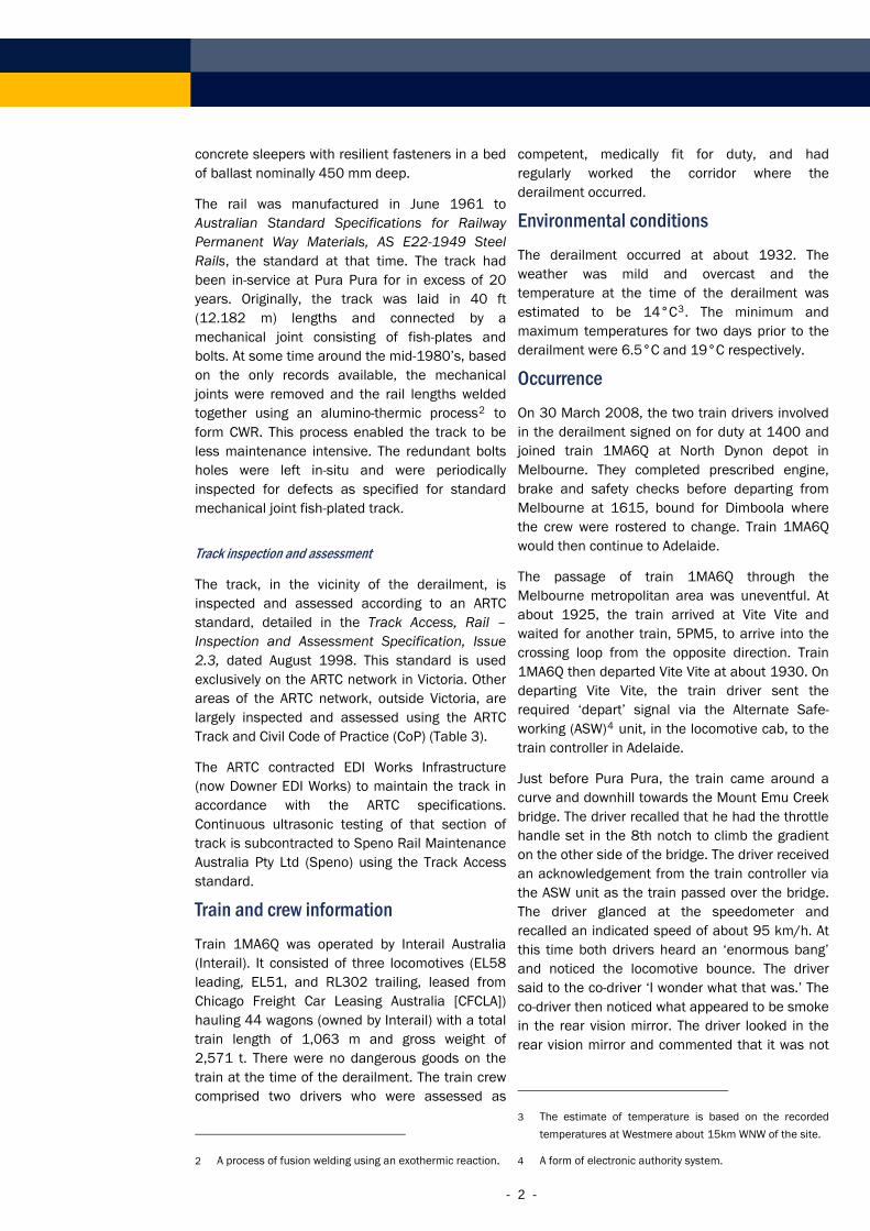
smoke, but dust. At this point, the driver observed that the brake pipe pressure gauge was indicating a ‘loss of air’. The driver left the throttle in the 8th notch until the train was nearly stopped to avoid the wagons bunching up. After stopping, the train brakes and locomotive handbrakes were applied to secure the train. Both drivers then walked back to the 21st wagon, RQKY2063, which had both bogies derailed. The driver called train control and the shift support officer and advised them of the occurrence before returning to the front of the train. The co-driver continued to walk further back to assess the other damage. Closer to the bridge the co-driver noticed a motor vehicle had stopped on the adjacent Vite Vite Road because the road had been blocked by large paper rolls thrown off the train during the derailment (Figure 2).
Figure 2: Large paper rolls thrown from train
Post occurrence
Emergency services started arriving at the site soon after the derailment was reported. The immediate derailment site area was cordoned off.
Both drivers of train 1MA6Q left the site at about 2330 and headed for home. On the way home, the crew were directed to undertake a breath test for the presence of alcohol and attended the nearest Police at Stawell. After returning zero readings from the breath test, the crew gave statements and left the Police station at about 0200 on 31 March 2008.
About 1,300 m of track was damaged. However, the Mount Emu Creek bridge was not damaged. Twenty-six wagons on train 1MA6Q received minor damage to wheels. Another 13 wagons were substantially damaged or destroyed, including the freight being transported.
Site restoration began on 31 March but was delayed due to severe weather conditions. The line was restored and re-opened at 0321 on 4 April 2008.
ANALYSIS On 30 March 2008, an investigation team from the Australian Transport Safety Bureau (ATSB) was despatched to investigate the derailment.
Evidence was sourced from the train drivers, Interail, the ARTC and Public Transport Safety Victoria (PTSV). Evidence included interviews, photographs, train running information, voice and data logs, engineering documentation, site surveys and other material.
Preliminary examination of the evidence established that there were no known mechanical defects or deficiencies with the train which would have contributed to the accident.
Sequence of events analysis The locomotive data loggers were downloaded and analysed. During the initial analysis, it was discovered that data from the leading locomotive, EL51, contained significant errors and could not be used for analysis. Similarly, data from locomotive EL58 contained errors and could not be used for analysis. Consequently, data from locomotive RL302 was used to determine the operating parameters of the train. Based on this data, at 1931:35 the train was travelling at about 98km/h at the point of derailment when the brake pipe pressure started to drop. The train travelled a further 868 m before coming to a stop 46 seconds later. Train 1MA6Q was handled in a manner consistent with normal driving practices. There was no evidence to suggest that train handling contributed in any way to the derailment.
Examination of on-site evidence found the first derailed wagon was located in the 9th position of the consist, with further wagons derailed in the 10th, 22nd, 24th - 28th, and the 30th to 42nd positions. The train had separated between the 30th, 31st and 32nd positions.
No wheel flange or dragging equipment marks were found on the track before the point of derailment. Examination of the wagons revealed no mechanical defects before the accident that could have contributed to the derailment. There was no evidence of wheel flats, that contribute to
- 3 -

excessive wheel impact loading, that could have contributed to the derailment.
Further examination of the site revealed a fractured rail on the Mount Emu Creek bridge, under the 43rd position in the consist (Figure 3).
Figure 3: The fractured rail in-situ
Of note was the deformation of the rail in the trailing section caused by the wheels ‘landing’ after traversing the fracture.
A large piece of rail head (Figure 4) was found directly below the fractured rail on the earth embankment beneath the bridge. It was determined to be the matching piece which had been ejected from the fractured rail above.
Figure 4: The ejected rail piece in-situ
On-site evidence suggests the following as the most likely derailment sequence:
• The passage of the previous train 5PM5 may have dislodged the portion of rail (Figure 4).
• The locomotives of train 1MA6Q travelled over the fractured rail and probably ejected the piece of rail head.
• The following wheelsets passed over the missing section and impacted the facing edge of the rail, intermittently derailing wheelsets. The more wheelsets that passed over the gap, the more the track deformed, which resulted in the derailment of further wheelsets.
Examination of fracture surfaces Portions of the fractured rail were taken to the ATSB Technical Analysis facilities in Canberra for a thorough examination. The following observations were made.
The rail was profiled and compared to a new rail profile (Figure 5). The total loss of head area was calculated to be 4.7 per cent. Given the age of the rail, the amount of head wear is well within the maximum specified limit of 35 per cent.
Figure 5: Rail profiles (actual versus new)
The rails were manufactured to AS E22-1949 Specification of steel rails, which was superseded by AS E22 1964 Specification of steel rails, and most recently by AS 1085.1-2002 Railway track material – Steel rails.
The fractured section of rail contained an alumino-thermic weld join in between two sets of three fishplate bolt-holes. The rail had fractured through the middle bolt-hole on each rail section.
For the purpose of the investigation, the fractures were labelled ‘A’ to ‘C’ in the direction of train travel (Figure 6).
Direction of travel
- 4 -

Figure 6: Fractured rail sections
The sections of track were laid out and the train direction identified (Figure 7). Pad marks on the base of the rail indicated the approximate location of the concrete sleepers.
Figure 7: Assembly of rail sections
The rail had completely fractured in two locations, effectively between two sleeper locations. The fractures at A and B were at a 45 degree angle, to the rail head, through the bolt-holes. Evidence of fatigue cracking was observed on the fracture surface at both bolt-holes. The surface of these cracks had oxidised to an extent that resembled the exterior rail surface and had therefore been open to atmosphere for a period of time prior to the derailment.
The largest fatigue crack extended 11 mm towards the head of the rail from the bolt-hole at fracture B (Figure 8).
Figure 8: Bolt-hole and fracture at ‘B’
The major fatigue crack at fracture A extended 5 mm towards the foot of the rail (Figure 9). No evidence of pre-existing cracking was observed on the fracture face at C.
Figure 9: Bolt-hole and fracture at ‘A’
The weld was sectioned and etched using 5 per cent nital solution (Figure 10).
Figure 10: Section of the heat affected zone
Direction of travel
C B A
Weld
Direction of travel
Sleeper locations
B
HAZ Weld
11 mm
5 mm
- 5 -
The heat affected zone (HAZ) extended about 30 mm from the weld up to the first bolt-hole. The second bolt-hole, with the fatigue crack origin, was about 130 mm outside the heat affected zone. The heat affected zone of the weld was not contributory to the initiation, propagation, or failure of the rail.
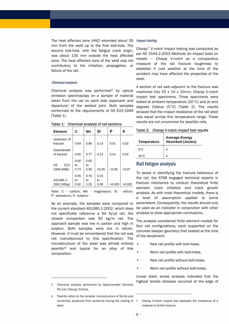
Chemical analysis
Chemical analysis was performed5 by optical emission spectroscopy on a sample of material taken from the rail on each side (approach and departure) of the welded joint. Both samples conformed to the requirements of AS E22-1949 (Table 1).
Table 1: Chemical analysis of rail sections
Element C Mn Si P S
Upstream of fracture 0.64 0.80 0.13 0.01 0.03
Downstream of fracture 0.65 0.77 0.13 0.01 0.02
AS E22-1949 (94lb)
0.60 to 0.73
0.60 to 0.90 <0.30 <0.05 <0.07
AS1085.1-2002 (50kg)
0.65 to 0.82
0.70 to 1.25
0.15 to 0.58 <0.025 <0.025
Note: C - carbon, Mn - magnesium, Si - silicon, P - potassium, S - sulphur
As an example, the samples were compared to the current standard AS1085.1-2002, which does not specifically reference a 94 lb/yd rail, the closest comparison was 50 kg/m rail. The approach sample was low in carbon and high in sulphur. Both samples were low in silicon. However, it must be remembered that the rail was not manufactured to this specification. The microstructure of the steel was almost entirely pearlitic6 and typical for an alloy of this composition.
5 Chemical analysis performed by Spectrometer Services
Pty Ltd, Coburg, Victoria.
6 Pearlite refers to the lamellar microstructure of ferrite and
cementite, produced from austenite during the cooling of
steel.
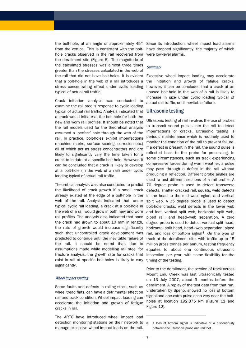
Impact testing
Charpy7 V-notch impact testing was conducted as per AS 1544.2-2003 Methods for impact tests on metals – Charpy V-notch as a comparative measure of the rail fracture toughness to establish if cold weather at the time of the accident may have affected the properties of the steel.
A section of rail web adjacent to the fracture was machined into 55 x 10 x 10mm, Charpy V-notch impact test specimens. Three specimens were tested at ambient temperature (20°C) and at zero degrees Celsius (0°C) (Table 2). The results showed that the impact resistance of the rail steel was equal across this temperature range. These results are not uncommon for pearlitic rails.
Table 2: Charpy V-notch impact test results
Temperature Average Energy Absorbed (Joules)
0°C 4
20°C 4
Rail fatigue analysis To assist in identifying the fracture behaviour of the rail, the ATSB engaged technical experts in fracture mechanics to conduct theoretical finite element, crack initiation and crack growth analysis. As with most theoretical models, there is a level of assumption applied to some parameters. Consequently, the results should only be used as an indicator in conjunction with other analysis to draw appropriate conclusions.
The analysis considered finite element models for four rail configurations, each supported on the concrete sleeper geometry that existed at the time of the derailment:
• New rail profile with bolt-holes.
• Worn rail profile with bolt-holes.
• New rail profile without bolt-holes.
• Worn rail profile without bolt-holes.
Linear static stress analysis indicated that the highest tensile stresses occurred at the edge of
7 Charpy V-notch impact test assesses the resistance of a
material to brittle fracture.
- 6 -
the bolt-hole, at an angle of approximately 45° from the vertical. This is consistent with the bolt-hole cracks observed in the rail recovered from the derailment site (Figure 6). The magnitude of the calculated stresses was almost three times greater than the stresses calculated in the web of the rail that did not have bolt-holes. It is evident that a bolt-hole in the web of a rail introduces a stress concentrating effect under cyclic loading typical of actual rail traffic.
Crack initiation analysis was conducted to examine the rail steel’s response to cyclic loading typical of actual rail traffic. Analysis indicated that a crack would initiate at the bolt-hole for both the new and worn rail profiles. It should be noted that the rail models used for the theoretical analysis assumed a ‘perfect’ hole through the web of the rail. In practice, bolt-holes exhibit imperfections (machine marks, surface scoring, corrosion etc.) all of which act as stress concentrators and are likely to significantly vary the time taken for a crack to initiate at a specific bolt-hole. However, it can be concluded that a crack is likely to develop at a bolt-hole (in the web of a rail) under cyclic loading typical of actual rail traffic.
Theoretical analysis was also conducted to predict the likelihood of crack growth if a small crack already existed at the edge of a bolt-hole in the web of the rail. Analysis indicated that, under typical cyclic rail loading, a crack at a bolt-hole in the web of a rail would grow in both new and worn rail profiles. The analysis also indicated that once the crack had grown to about 10 mm in length, the rate of growth would increase significantly such that uncontrolled crack development was predicted to continue until the inevitable failure of the rail. It should be noted that, due to assumptions made while modelling rail steel for fracture analysis, the growth rate for cracks that exist in rail at specific bolt-holes is likely to vary significantly.
Wheel impact loading
Some faults and defects in rolling stock, such as wheel tread flats, can have a detrimental effect on rail and track condition. Wheel impact loading can accelerate the initiation and growth of fatigue cracks in rail.
The ARTC have introduced wheel impact load detection monitoring stations on their network to manage excessive wheel impact loads on the rail.
Since its introduction, wheel impact load alarms have dropped significantly, the majority of which were low-level alarms.
Summary
Excessive wheel impact loading may accelerate the initiation and growth of fatigue cracks, however, it can be concluded that a crack at an unused bolt-hole in the web of a rail is likely to increase in size under cyclic loading typical of actual rail traffic, until inevitable failure.
Ultrasonic testing Ultrasonic testing of rail involves the use of probes to transmit sound pulses into the rail to detect imperfections or cracks. Ultrasonic testing is periodic maintenance which is routinely used to monitor the condition of the rail to prevent failure. If a defect is present in the rail, the sound pulse is reflected back to the probe for processing. In some circumstances, such as track experiencing compressive forces during warm weather, a pulse may pass through a defect in the rail without producing a reflection. Different probe angles are used to test different sections of a rail profile. A 70 degree probe is used to detect transverse defects, shatter cracked rail, squats, weld defects in the head to the mid web region, and vertical split web. A 35 degree probe is used to detect bolt-hole cracks, weld defects in the lower web and foot, vertical split web, horizontal split web, piped rail, and head–web separation. A zero degree probe is used to detect vertical split head, horizontal split head, head–web separation, piped rail, and loss of bottom signal8. On the type of track at the derailment site, with traffic up to 15 million gross tonnes per annum, testing frequency equates to about one continuous ultrasonic inspection per year, with some flexibility for the timing of the testing.
Prior to the derailment, the section of track across Mount Emu Creek was last ultrasonically tested on 13 July 2007, about 9 months before the derailment. A replay of the test data from that run, undertaken by Speno, showed no loss of bottom signal and one extra pulse echo very near the bolt-holes at location 192.875 km (Figure 11 and Figure 12).
8 A loss of bottom signal is indicative of a discontinuity
between the ultrasonic probe and rail foot.
- 7 -

- 8 -
Figure 11: Extra pulse echo in replay On 1 December 2008, the ARTC issued a new Engineering (Track and Civil) Instruction ETI-01-05 ‘resolving issues from previous standards’ (Figure 13). The new instruction standardises the response times and actions for bolt-hole cracks across the ARTC network. In particular, the response and action for bolt-hole cracks less than 20 mm in size for both type ‘A’ and ‘B’ tracks, meaning that any crack detected in unused bolt-holes must be removed within a specified timeframe. This new standard exceeds the requirements of the ARTC Victorian standard for bolt-holes between 11-20 mm requiring removal within 30 days for ‘B’ track.
History of similar incidents Figure 12: Close-up of extra pulse echo
Canada
On the day of the testing, the operator detected this anomaly and requested that the hand tester following the Speno car conduct a closer examination with a handheld ultrasonic testing device. A defect report automatically generated by this inspection concluded that No Sizable Defect (NSD)9 was detected, meaning that no further action was required even though the evidence suggests that the fatigue cracks probably existed (to some degree) at the time of the ultrasonic testing
On 24 October 2002, a Canadian National train derailed six cars near Hibbard, Quebec. Six cars were damaged and 275 m of track was destroyed. There were no injuries and no permanent environmental damage. Laboratory testing revealed that cracks originating from either side of the splice bar bolt-hole and propagated longitudinally through the rail web. ‘The longitudinal fracture in the rail was present for some time, and originated at a splice bar bolt-hole that acted as a stress raiser, since it intersected rail markings, its edges were not chamfered, and it had been heated in the drilling process.’ The Transportation Safety Board of Canada (TSB) report number R02D0113 indicated that Canadian National recommended the removal of bolt-holes from CWR for this reason:
Canadian National's SPC 1303 recommends that rails with holes be sawn when jointed rail is converted to CWR, because leaving unused bolt-holes in CWR is not recommended due to stress raisers and the risk of cracking inherent in this structural detail.
The ARTC Track and Civil Code of Practice
Table 3 shows the difference in response times for defects in bolt-holes, particularly for defects of less than 20 mm in size. The existing ARTC Victorian standard has a response time of no more than 90 days to remove the defect whereas the ARTC CoP required no action.
9 NSD - a term used by SPENO meaning that no defect
could be found.

Table 3: Bolt-hole defect classification
Defect size
ARTC Track Access standard Victoria ARTC CoP10
Response time Action Response time Action
Less than 20 mm
90 days Remove Nil N/A
20–40 mm 30 days Remove 30 days Reassess or remove
40–75 mm 7 days Remove 7 days Reassess or remove
Greater than 75 mm
Immediate Speed restrict and reassess every day, or remove
Prior to passage of next train
Speed restrict and reassess every day, or remove
Broken rail Immediate Pilot or remove Prior to passage of next train
Pilot or remove
Figure 13: New Engineering (Track and Civil) Instruction ETI-01-05
10 Denotes ARTC Code of Practice used outside Victoria on ‘B’ track.
- 9 -

Summary Results from the finite element modelling indicated that when a crack has grown to about 10 mm in length, the rate of growth will increase significantly such that uncontrolled crack development is predicted to continue until the inevitable failure of the rail. In the section of rail which failed and led to the derailment on the Mt Emu Creek bridge, the primary fatigue crack was 11 mm in length, and that it probably grew at an increasing rate until the failure of the rail was inevitable.
The origin of the cracks at the bolt-holes, the absence of material defects, and the results of the finite element modelling, suggest that the bolt-holes alone were sufficient stress concentrators to result in the initiation and propagation of fatigue cracking, ultimately leading to the rapid failure of the rail section.
FINDINGS Context At about 1932 on 30 March 2008, freight train 1MA6Q derailed on the Mt Emu Creek bridge near Pura Pura, Vic., as a result of a failed rail due to fatigue cracking emanating from a bolt-hole in the rail web.
From the evidence available, the following findings are made with respect to the derailment of train 1MA6Q and should not be read as apportioning blame or liability to any particular organisation or individual.
Contributing Safety Factors • The rail at the derailment site had low-load
high-cycle fatigue cracking emanating from the unused bolt-holes in the rail web.
• Unused bolt-holes in the rail web are sufficient stress concentrators to result in the initiation and propagation of fatigue cracking, ultimately leading to the failure of the rail. [Safety issue]
• A single extra pulse echo was recorded during the last ultrasonic inspection of the rail, nine months before the derailment, in the vicinity of the failure. An examination with handheld ultrasonic testing equipment at the time concluded there was no sizable defect in the rail, even though the evidence suggests that
the fatigue cracks existed (to some degree) at the time. [Safety issue]
Other key findings • The ARTC standards used exclusively on the
ARTC network in Victoria differed from other areas of the ARTC network. This issue has since been addressed by the ARTC.
• The train crew were competent, medically fit for duty.
• Examination of the wagons revealed no mechanical defects before the accident that could have contributed to the derailment.
• Data from the leading locomotive, EL51, contained significant errors and could not be used for analysis. Similarly, data for locomotive EL58 contained errors and could not be used for analysis.
• There was no evidence to suggest that train handling contributed in any way to the derailment.
• The rail material complied with the relevant standard with respect to its mechanical and chemical properties at the time of manufacture, was not excessively worn, and had an equal impact resistance across various ambient temperature ranges.
SAFETY ACTION The safety issues identified during this investigation are listed in the Findings and Safety Actions sections of this report. The Australian Transport Safety Bureau (ATSB) expects that all safety issues identified by the investigation should be addressed by the relevant organisation(s). In addressing those issues, the ATSB prefers to encourage relevant organisation(s) to proactively initiate safety action, rather than to issue formal safety recommendations or safety advisory notices.
All of the responsible organisations for the safety issues identified during this investigation were given a draft report and invited to provide submissions. As part of that process, each organisation was asked to communicate what safety actions, if any, they had carried out or were planning to carry out in relation to each safety issue relevant to their organisation..
- 10 -

- 11 -
Australian Rail Track Corporation Unused rail bolt-holes
Safety Issue
Unused bolt-holes in the rail web are sufficient stress concentrators to result in the initiation and propagation of fatigue cracking, ultimately leading to the failure of the rail.
Action taken by the ARTC
The ARTC has introduced a common standard for bolt-hole crack limits across the whole ARTC network. The standard has lower thresholds for intervention.
ATSB assessment of response/action
Although the ARTC has addressed the risk of crack propagation in unused rail bolt-holes, the risk of crack initiation still exists under cyclic loading typical of actual rail traffic.
ATSB safety recommendation RO-2008-004-SR-012
The Australian Transport Safety Bureau recommends that the ARTC take further action to address this safety issue.
Ultrasonic rail testing limitations
Safety Issue
A single extra pulse echo was recorded during the last ultrasonic inspection of the rail, nine months before the derailment, in the vicinity of the failure. An examination with handheld ultrasonic testing equipment at the time concluded there was no sizable defect in the rail, even though the evidence suggests that the fatigue cracks existed (to some degree) at the time.
ATSB safety recommendation RO-2008-004-SR-011
The Australian Transport Safety Bureau recommends that the ARTC take action to address this safety issue.
SOURCES AND SUBMISSIONS Under Part 4, Division 2 (Investigation Reports), Section 26 of the Transport Safety Investigation Act 2003, the Executive Director may provide a draft report, on a confidential basis, to any person whom the Executive Director considers
appropriate. Section 26 (1) (a) of the Act allows a person receiving a draft report to make submissions to the Executive Director about the draft report.
A draft of this report was provided to the Australian Rail Track Corporation, Interail, Chicago Freight Car Leasing Australia, Public Transport Safety Victoria, Office of the Chief Investigator Victoria, and a number of individuals.
Submissions were received from the Australian Rail Track Corporation, Chicago Freight Car Leasing Australia, Interail, Public Transport Safety Victoria, Office of the Chief Investigator Victoria, and a number of individuals. The submissions were reviewed and where considered appropriate, the text of the report was amended accordingly.
The Australian Rail Track Corporation also noted:
Australian Rail Track Corporation has invested heavily in wayside monitoring equipment to measure and record wheel impact loadings and is working with its customers to identify and remove "rogue" wheel sets.