Embed Size (px)
Citation preview

UNCLASSIFIED
Generic modification of compressed oxygen self-rescuers for use in
compressed air tunnels at pressures of 0.0 to 3.5 bar gauge (U)
DERA/CHS/PPD/CR010025/1.0 Copy of 20
Cover + x + 54 pages
April 2001
T G Anthony M J Woolcott
This document is subject to the release conditions printed on the reverse of this page
UNCLASSIFIED

UNCLASSIFIED
This document has been prepared for HSE and, unless indicated, may be used and circulated in accordance with the conditions of the Order
under which it was supplied.
HSE Research Contract: 3998/R46.078
It may not be used or copied for any non-Governmental or commercial purpose without the written agreement of DERA.
© Crown copyright 2001 Defence Evaluation and Research Agency UK
Approval for wider use or release must be sought from:
Intellectual Property Department
Defence Evaluation and Research Agency Farnborough, Hampshire GU14 0LX
ii DERA/CHS/PPD/CR010025/1.0 UNCLASSIFIED

UNCLASSIFIED
Authorisation Prepared by T G Anthony
Title Principal Scientist Signature
Date April 2001
Location DERA Alverstoke
Authorised by M G White
Title Principal Scientist Signature
Date April 2001 Principal authors Name T G Anthony
Appointment Principal Scientist
Location DERA Alverstoke Name M J Woolcott
Appointment Engineer
Location DERA Alverstoke
DERA/CHS/PPD/CR010025/1.0 iii UNCLASSIFIED

UNCLASSIFIED
Record of changes
This is a controlled document. Additional copies should be obtained through the issuing authority. In the extreme event of copying locally, each document shall be marked “Uncontrolled Copy”. Amendment shall be by whole document replacement. Proposals for change to this document should be forwarded in writing to DERA Alverstoke, Gosport.
Issue Date Details of changes 1.0 April 2001
iv DERA/CHS/PPD/CR010025/1.0 UNCLASSIFIED
UNCLASSIFIED
Abstract
A range of techniques has been used to provide breathing apparatus for use during normobaric tunnelling operations. Tunnelling work may also be conducted at elevated pressures up to 3.5 bar gauge; currently available respiratory protection systems are not appropriate for these operations due to limited endurance and the toxic effect of oxygen at elevated inspired partial pressure.
A mathematical model has been developed to predict the inspired partial pressure of oxygen within a modified self-rescue system at hyperbaric pressures (0.0 to 3.5 bar gauge). The model uses a semi-closed circuit breathing apparatus principle and considers the percentage of oxygen in the gas mixture, gas flow rate, work rate of the user and gas endurance.
The model has allowed three ‘operational envelopes’ for hyperbaric self-rescue systems to be identified that use gas mixtures and flow rate that are practical in use and would give adequate endurance (15 minutes minimum).
A proof of principle semi-closed circuit system was produced by modification of a current closed circuit oxygen system. The modified system complied with both the current atmospheric pressure breathing performance requirements (BS EN 400) and requirements for hyperbaric pressures (NPD/DEn guidelines). It also demonstrated that the carbon dioxide absorbent system would have adequate endurance under hyperbaric conditions.
DERA/CHS/PPD/CR010025/1.0 v UNCLASSIFIED

UNCLASSIFIED
This page is intentionally blank
vi DERA/CHS/PPD/CR010025/1.0 UNCLASSIFIED
UNCLASSIFIED
List of contents Authorisation iii Record of changes iv Abstract v List of contents vii List of tables ix List of figures ix 1 Introduction 1 2 Aim 2 3 Requirements 3 3.1 General 3 3.2 Physiological 3 4 Review of existing systems 5 4.1 Filter systems 5 4.2 Compressed air systems 5 4.3 Chemical oxygen systems 5 4.4 Compressed oxygen 6 4.5 Manufacturers 7 4.6 Equipment for modification 7 5 Modelling 10 5.1 Principle of semi-closed circuit breathing apparatus 10 5.2 Inspired gas 11 5.3 Gas endurance 14 6 Design and modification 16 6.1 General 16 6.2 Gas supply - cylinder 16 6.3 Gas supply - principle of constant mass flow 17 6.4 Gas supply - first stage regulator assembly 17 6.5 Gas supply - second stage regulator 18 6.6 Three-way manifold and variable orifice (metering valve) 18 6.7 Apparatus carry case 19
DERA/CHS/PPD/CR010025/1.0 vii UNCLASSIFIED

UNCLASSIFIED
List of contents
7 Unmanned testing 22 7.1 General 22 7.2 Modified first stage regulator performance 22 7.3 Metering valve (sonic orifice) performance 23 7.4 Breathing performance 24 7.5 Apparatus endurance (carbon dioxide absorbent canister) 31 8 Discussion 35 9 Summary 37 10 References 38 11 Acknowledgements 40 12 List of abbreviations 41 Appendices A Pressure units 43 B Existing apparatus 45 C Derivation of steady state equation 49 D Proposed specification 51 List of appendix tables Table D-1: Proposed specification for hyperbaric self-rescue systems 51 Table D-2: Proposed colour scheme for hyperbaric self-rescue systems 52 Distribution list 53 Report documentation page
viii DERA/CHS/PPD/CR010025/1.0 UNCLASSIFIED

UNCLASSIFIED
List of contents
List of tables Table 3-1: Maximum oxygen breathing times for RN divers 4 Table 5-1: Predicted cylinder sizes (volume and pressure) and gas endurances 15 Table 7-1: Ventilation rates 25 Table 7-2: Breathing performance of standard EBA 6.5 unit (BS EN 400) 26 Table 7-3: Carbon dioxide absorbent canister - endurance tests 32 List of figures Figure 4-1: Principle of closed-circuit compressed oxygen self-rescue device 7 Figure 4-2: Ocenco Inc EBA 6.5 self-contained self-rescuer 9 Figure 5-1: Principle of a semi-closed circuit re-breather 10 Figure 5-2: Concept for semi-closed circuit self-rescue device 11 Figure 5-3: Operational envelope 1 for use in tunnels at pressures in the range 0.0 to 1.5 bar gauge 13 Figure 5-4: Operational envelope 2 for use in tunnels at pressures in the range 1.0 to 2.0 bar gauge 13 Figure 5-5: Operational envelope 3 for use in tunnels at pressures in the range 1.5 to 3.5 bar gauge 14 Figure 6-1: Standard regulator assembly 20 Figure 6-2: Modified regulator assembly 21 Figure 7-1: Interstage pressure for ambient pressures from 0.0 to 4.0 bar gauge 22 Figure 7-2: Flow rate (STPD) for ambient pressures of 0.0 and 4.0 bar gauge 23 Figure 7-3: Modified unit rigged for unmanned testing 25 Figure 7-4: Schematic of pressure-volume loop measurement; closed circuit 26 Figure 7-5: Breathing performance, comparison of work of breathing 28 Figure 7-6: Breathing performance, comparison of peak-to-end respiratory pressure 29 Figure 7-7: Breathing performance, comparison of peak-to-end respiratory pressure 30 Figure 7-8: Component parts of disassembled absorbent canister 31 Figure 7-9: Canister endurances showing CO2 absorbent comparison 34 Figure 7-10: Canister endurances showing depth comparison 34
DERA/CHS/PPD/CR010025/1.0 ix UNCLASSIFIED

UNCLASSIFIED
This page is intentionally blank
x DERA/CHS/PPD/CR010025/1.0 UNCLASSIFIED

UNCLASSIFIED
1 Introduction 1.1 Employers are required to provide tunnel workers with self-rescue devices to enable
them to move to a place of safety in the event of a fire or other event that may cause an irrespirable atmosphere. The atmosphere may be irrespirable due to the air becoming hypoxic (oxygen content of the air being consumed by fire), the presence of noxious or toxic gases and smoke.
1.2 Self-rescue devices may be either worn by the user or placed at readily available and
strategic positions in the tunnel working. The devices are typically required to provided the user with a respirable gas for a period of at least 15 minutes whilst conducting hard work.
1.3 The European Community has issued a Personnel Protective Equipment (PPE) directive
[1] that requires equipment such as self-rescue devices to be fit for purpose. A range of techniques, and European standards defining performance requirements, have been used to provide breathing apparatus for use during normobaric tunnelling operations that are ‘fit for purpose’. Current equipment and standards for self-rescue and escape apparatus have been developed for use at normobaric pressure [2,3,4,5,6].
1.4 Tunnelling work may also be conducted at elevated pressures up to 3.5 bar gauge (A
review of pressure units used in this report and for working at pressure is presented at appendix A). This presents several problems with respect to currently available self-rescue devices: The endurance of conventional compressed air systems would be inadequate and systems using oxygen as the breathing gas have a significant risk of the user developing Central Nervous System (CNS) oxygen toxicity (i.e. having a fit and losing consciousness) [7].
1.5 To overcome the shortfall in self-rescue systems for use at hyperbaric pressures it was
thought that technology traditionally used for diving systems in the pressure range 0.0 to 5.0 bar gauge may be employed. In liaison with the HSE, and based on experience with the development and testing of diving breathing apparatus, DERA (Alverstoke) proposed that a solution may be achieved by modification of existing oxygen self-rescuers. Thus DERA (Alverstoke) were tasked under HSE RSU Contract 3998/R46.078 to investigate the ‘Generic modification of oxygen self-rescuers for use in compressed air tunnels between 1.0 and 3.5 bar’; this report presents the work completed for the contract.
DERA/CHS/PPD/CR010025/1.0 Page 1 of 54 UNCLASSIFIED

UNCLASSIFIED
2 Aim 2.1 The DERA research programme proposed that a generic modification may be applied to
current compressed oxygen closed-circuit systems such that they could meet the requirements of the European Personal Protective Equipment (PPE) directive whilst providing adequate performance at ambient pressures from 0.0 to 3.5 bar gauge [8].
2.2 The proposed modification would consider the use of semi-closed circuit technology as
currently applied to diving re-breather systems. This technology would enable oxygen in nitrogen breathing gas mixtures to be employed to overcome the hyperoxic problems associated with oxygen-only systems.
2.3 The aim of the programme was specifically to: 2.3.1 Review current closed-circuit self-rescue devices to identify systems and techniques
suitable for generic modification. 2.3.2 Conduct a theoretical assessment of semi-closed circuit techniques for self-rescue in
ambient pressures of 0.0 to 3.5 bar gauge. 2.3.3 Construct a prototype system with generic modification. 2.3.4 Conduct un-manned testing of the modified system to demonstrate the feasibility and
expected compliance with PPE directive. 2.3.5 Propose manned testing and evaluation of the prototype.
Page 2 of 54 DERA/CHS/PPD/CR010025/1.0 UNCLASSIFIED

UNCLASSIFIED
3 Requirements 3.1 General 3.1.1 A range of criteria was used to define the performance of a functional system for use at
hyperbaric pressures. 3.1.2 The modified equipment was required to be safe in storage and operation at ambient
pressures in the range 0.0 to 3.5 bar gauge. 3.1.3 It should provide respiratory protection to a user at rest or performing hard work at
ambient pressures in the range 0.0 to 3.5 bar gauge. 3.1.4 The endurance of the apparatus should be a minimum of 15 minutes with a preferred
endurance of 30 minutes. 3.1.5 The system should be capable of being deployed (wall mounted) at strategic positions in
Tunnel working and to be carried by the user or on a transportation system. 3.2 Physiological 3.2.1 The modified equipment was required to comply with the requirements of the PPE
directive by being ‘fit for purpose’. To demonstrate compliance the breathing performance should, where appropriate, comply with the requirements of the relevant British Standard [2-6] for normobaric use and with the Norwegian Petroleum Directorate (NPD)/Department of Energy (DEn) guidelines promulgated for underwater breathing apparatus [9] (underwater breathing apparatus is intended for use under severe hyperbaric conditions).
3.2.2 The system should have the ability to provide ‘first breath’ protection (i.e. when first
donning the apparatus the user should be able to initially inhale respirable gas from the apparatus prior to exhaling).
3.2.3 The inspired partial pressure of oxygen (PO2) was required to be maintained at a level
that would prevent the user becoming hypoxic or hyperoxic with the associated risk of CNS oxygen toxicity [7].
3.2.3.1 The inspired PO2 of normobaric air is nominally 0.21 bar. Although inspired PO2 levels
down to 0.17 bar are considered to be physiologically acceptable for self-rescue systems [2-5] it was felt that a higher level would provide an increased level of safety. A minimum inspired PO2 of 0.20 was used as the equipment requirement.
3.2.3.2 The Royal Navy regularly conduct diving operations where the diver is breathing oxygen
at an elevated inspired PO2 and conducting hard work (i.e. swimming hard). The maximum permissible exposure times for RN divers breathing an elevated inspired PO2 is presented in the UK Military diving manual BR 2806 [10] and presented in Table 3-1.
DERA/CHS/PPD/CR010025/1.0 Page 3 of 54 UNCLASSIFIED

UNCLASSIFIED
Reguirements
Depth of dive m
Inspired PO2Bar
Maximum exposure (dive) time Minutes
8 1.8 240 9 1.9 80
11 2.1 25 12 2.2 15 15 2.5 10
Table 3-1: Maximum oxygen breathing times for RN divers
3.2.3.3 For conventional diving applications the HSE have indicated that the maximum inspired
PO2 should not exceed 1.5 bar. However, as the self rescue system may be used for a period of up to 30 minutes, then the RN diving limits suggest that the maximum inspired PO2 should not exceed 1.9 bar. However, a prospective user of a hyperbaric self-rescue system may have been breathing air at hyperbaric pressure for a significant period (possibly hours) before breathing from the system. Allowing for a combination of the two oxygen exposures a maximum inspired PO2 of 1.80 bar was used as the equipment requirement.
3.2.4 Wearers of self-rescue apparatus may be required to spend periods at rest breathing from
the system and at other times performing hard work; oxygen consumption varies significantly between these extremes. It is felt that a system should be able to supply gas (with an inspired oxygen partial pressure in the range 0.2 to 1.8 bar) when the wearer is consuming oxygen in the range 0.25 lmin-1 STPD (equivalent to being at rest - sitting or lying) to 3.00 lmin-1 STPD (equivalent to working hard - running or climbing) [7].
Page 4 of 54 DERA/CHS/PPD/CR010025/1.0 UNCLASSIFIED

UNCLASSIFIED
4 Review of existing systems 4.1 Filter systems 4.1.1 Escape apparatus to BS EN 403 - ‘Filtering respiratory devices with hood for self-rescue
from fire’ [11] are not considered to be appropriate for escape from either normobaric or hyperbaric tunnel workings. The devices only offer protection from toxic and noxious gases. They do not offer any protection from depletion of oxygen in a fire; the user would in this situation suffer hypoxia and potentially loose consciousness.
4.2 Compressed air systems 4.2.1 Current standards for compressed air systems for normobaric operations are:
• BS EN 402 - Self-contained open-circuit compressed air breathing apparatus with full face mask or mouthpiece [4].
• BS EN 1146 - Self-contained open-circuit compressed air breathing apparatus
incorporating a hood [6]. 4.2.2 The gas supplies for open circuit compressed air systems (both BS EN 402 open circuit
demand systems, and BS EN 1146 open circuit free flow systems) are designed for normobaric (0.0 bar gauge, atmospheric pressure) applications. Under hyperbaric conditions the ventilation requirement for both demand and free flow systems remains essentially unchanged in respect of gas flows at Ambient Temperature and Pressure (ATP). However, the gas flow requirement at Standard Temperature and Pressure (STP, 1.013 bar and 0 °C) increases directly in proportion to the absolute pressure of the tunnel working. Thus at a hyperbaric pressure of 3.5 bar gauge (4.5 bar absolute) the gas requirement would be 4.5 times that required at normobaric pressure (0.0 bar gauge).
4.2.3 The increased gas requirement of compressed air systems at under hyperbaric conditions
means that the current systems would have an endurance that is reduced directly in proportion to the absolute pressure. Alternatively to maintain the same endurance, the gas supply (cylinder size and capacity) would have to be increased directly in proportion to the absolute pressure; this would make the device too bulky and heavy for practical use.
4.3 Chemical oxygen systems 4.3.1 Current standards for chemical oxygen systems for normobaric operations are:
• BS EN 401 - Self-contained closed-circuit breathing apparatus - Chemical oxygen (KO2) escape apparatus [3].
• BS EN 1061 - Self-contained closed-circuit breathing apparatus - Chemical
oxygen (NaClO3) escape apparatus [5].
DERA/CHS/PPD/CR010025/1.0 Page 5 of 54 UNCLASSIFIED

UNCLASSIFIED
Review of existing systems
4.3.2 Closed circuit oxygen systems complying with the requirements of BS EN 401 and 1061 use a recirculating system whereby the user exhales into and inhales from a breathing bag (also know as a counterlung), exhaled carbon dioxide is removed by alkali absorbent material and oxygen is supplied by a chemical cartridge (either potassium superoxide, KO2 or sodium chlorate, NaClO3) - with the potassium superoxide system the chemical cartridge also acts as the alkali absorbent. Excess gas is vented from the system by a relief valve.
4.3.3 Other chemical systems currently not covered by a BS EN use a free flow of oxygen
from a chemical cartridge in a similar manner to open circuit compressed air, free flow systems.
4.3.4 The problem with use of chemical systems at hyperbaric pressure is two fold: 4.3.4.1 The gas in the breathing bag would contain a high percentage of oxygen increasing to
almost 100% after the system has been used for a few minutes. This high percentage of oxygen would at hyperbaric conditions greater than 0.8 bar gauge give rise to inspired PO2 greater than 1.8 bar and predispose the user to Central Nervous System (CNS) oxygen toxicity - (para 3.2.3) [7].
4.3.4.2 In addition it is feasible under increased pressure that the chemical systems - particularly
the systems using sodium chlorate (NaClO3) - would produce oxygen at an increased rate reducing the endurance of the system [12].
4.4 Compressed oxygen systems 4.4.1 The current standard for compressed oxygen systems for normobaric operations is:
• BS EN 400 - Self-contained closed-circuit breathing apparatus - Compressed oxygen escape apparatus [2].
4.4.2 Closed circuit compressed oxygen systems complying with the requirements of BS
EN 400 are similar in principle to chemical systems and use a recirculating system. The user exhales into and inhales from a breathing bag (also know as a counterlung), exhaled carbon dioxide is removed by alkali absorbent material and oxygen is supplied from a high pressure cylinder at a constant flow (typically 1.5 lmin-1). Excess gas is also vented from the system by a relief valve. The principle is illustrated in Figure 4.1.
4.4.3 The problem with the use of closed-circuit compressed oxygen systems at hyperbaric
pressure is similar to the problems associated with chemical systems in that the gas in the breathing bag would contain a high percentage of oxygen increasing to almost 100%. This at hyperbaric conditions greater than 0.8 bar gauge would give rise to inspired PO2 greater than 1.8 bar and predispose the user to Central Nervous System (CNS) oxygen toxicity - (para 3.2.3) [7].
Page 6 of 54 DERA/CHS/PPD/CR010025/1.0 UNCLASSIFIED

UNCLASSIFIED
Review of existing systems
Excess gasVented
Counterlung
CO2
AbsorbentOneway
valves
Oxygen - O2Demand
orConstant flow
~ 1.5 l/min
Figure 4-1: Principle of closed-circuit compressed oxygen self rescue device 4.5 Manufacturers 4.5.1 A review of commercially available self-rescue systems was conducted by internet
search, discussion with Compressed Air Working Group (CAWG) members and the authors personal experience.
4.5.2 Current self-rescue system manufacturers and their products are presented at appendix B. 4.5.3 During the review it was found that several units that were thought to be available have
now been discontinued and are not available for purchase. Although attempts were made to make the review comprehensive, it is also expected that other units may be available.
4.6 Equipment for modification 4.6.1 As discussed, the compressed air systems are such that a significant increase in gas
supply is required for use under hyperbaric conditions. Compressed air cylinder capacities (in respect of material, mass, volume and charging pressure) to meet the requirement are not considered feasible for practical use.
4.6.2 The operating principle of closed-circuit oxygen self-rescue systems is such that they
maintain a constant supply of oxygen to the breathing loop. To overcome the problem of CNS oxygen toxicity under hyperbaric conditions it is necessary to limit and control the oxygen concentration within the breathing mixture such that the inspired PO2 remains within the proposed limits of 0.2 to 1.8 bar. This is typically achieved by including a diluent gas (nitrogen) with the oxygen in the breathing loop. Thus a supply of nitrogen for the breathing circuit is also required.
4.6.3 Closed circuit chemical oxygen systems are only able to supply (chemically) oxygen to
the breathing circuit. As a nitrogen or other diluent gas supply is not available (or the equipment easily modified to supply nitrogen) the ability to provide and control the level
DERA/CHS/PPD/CR010025/1.0 Page 7 of 54 UNCLASSIFIED

UNCLASSIFIED
Review of existing systems
of oxygen and nitrogen in the breathing circuit in chemical oxygen systems is not considered to be practically feasible for hyperbaric use.
4.6.4 Closed circuit self-rescue systems are currently configured to supply oxygen at a constant
mass flow rate to the breathing circuit from a small compressed gas cylinder. However, divers breathing apparatus use this closed circuit principle for breathing both pure oxygen at shallow depths (typically pressures from 0.0 to 0.8 bar gauge) and oxygen and nitrogen mixtures at greater depths (typically up to a pressure of 5.0 bar gauge) [10]. These systems may be configured to maintain the oxygen concentration within the breathing circuit within acceptable physiological limits.
4.6.5 Thus the aim of this project was to demonstrate a generic modification that may be
applied to compressed oxygen closed-circuit systems to enable safe use at hyperbaric pressures. The modification would consider the use of semi-closed circuit technology to introduce nitrogen into the breathing circuit as currently applied to diving re-breather systems.
4.6.6 The review of self-rescue devices (appendix B) identified only three manufacturers of
closed circuit self-rescue systems. Unfortunately, on further investigation it was found that the systems from two of the manufacturer were obsolete and not currently in production or available for modification. Of the two units produced by the only manufacturer in current production (Ocenco Inc, Wisconsin, USA) the smaller unit (M20-2; CE marked to BS EN 400) was unsuitable for modification as it would not be able to hold an adequate gas supply or provide the required overall endurance. However, the larger unit (EBA 6.5; not currently CE marked) was considered to be acceptable for demonstration of a generic model. Thus units were obtained for modification and subsequent testing.
4.6.7 Ocenco EBA 6.5: Specification:
• Total mass 3.583 kg • Donned mass 2.910 kg • Dimensions (0.216 m x 0.300 m x 0.114 m) • Cylinder 207 bar, 0.75 litre water capacity • Demand (for first breath protection) and constant flow supply • Carbon dioxide absorbent Lithium Hydroxide (LiOH) • Claimed endurance (as oxygen system) 110 minutes
The system is illustrated in Figure 4-2.
Page 8 of 54 DERA/CHS/PPD/CR010025/1.0 UNCLASSIFIED

UNCLASSIFIED
Review of existing systems
Figure 4-2: Ocenco Inc EBA 6.5 self-contained self-rescuer
DERA/CHS/PPD/CR010025/1.0 Page 9 of 54 UNCLASSIFIED

UNCLASSIFIED
5 Modelling 5.1 Principle of semi-closed circuit breathing apparatus 5.1.1 A closed-circuit oxygen system (illustrated in Figure 4-1) typically uses either a constant
flow of oxygen approximating to physiological requirement (in the order of 1.5 l min-1) into the breathing circuit or a demand system where additional oxygen to replace that consumed is added by the user inhaling. If there is excess gas in the system it is vented through an exhaust valve. Under ideal conditions the volume of oxygen entering the circuit is the same as that being consumed with no gas being lost from the system. The systems are thus considered to be ‘closed-circuit’.
5.1.2 In a closed-circuit oxygen system (that has been purged of nitrogen from initial start-up)
the only inspired gas is that from the supply system, i.e. oxygen. Thus the inspired PO2 is dependent only upon the ambient pressure.
5.1.3 With a semi-closed circuit system, a constant mass flow of gas is supplied to the
breathing circuit. This is a mixture of oxygen and nitrogen, oxygen is consumed by the wearer and so to prevent all the oxygen being consumed and the breathing mixture becoming hypoxic, it is necessary to provide a constant flow of gas through the breathing circuit. Thus, oxygen rich gas is constantly being added to the circuit and oxygen lean gas vented through the exhaust and so the system is known as ‘semi-closed circuit’.
5.1.4 Inherent in a semi-closed circuit system is the principle that as some of the oxygen
supplied is consumed by the user the concentration of oxygen in the counter-lung is less than that in the gas cylinder and supplied to the system (Figure 5-1).
Excess gas Vented
Inhaled gasO2 %
N2 %
Constant Flow Less O2
consumed
Exhaled gas
Counter-lung
O2 %Less thanin cylinder
Figure 5-1: Principle of a semi-closed circuit re-breather
Page 10 of 54 DERA/CHS/PPD/CR010025/1.0 UNCLASSIFIED

UNCLASSIFIED
Modelling
5.2 Inspired gas 5.2.1 As discussed to use a self-rescuer under hyperbaric conditions it is essential that the
inspired PO2 be maintained between 0.2 and 1.8 bar. Factors affecting the inspired PO2 are:
• % oxygen in supply gas • Ambient pressure • Users oxygen consumption (VO2 , lmin-1 STPD) • Supply gas flow rate (lmin-1 STPD)
Note: Standard Temperature and Pressure Dry (STPD).
5.2.2 In a compressed air tunnel working two of the parameters are independent of the self-
rescue system i.e. the ambient pressure and the work rate of the user. Thus the inspired PO2 has to be maintained within limits by controlling the percentage of oxygen in the supply gas and the gas flow into the breathing circuit (Figure 5-2).
Excess gasVented
Counterlung
CO2
AbsorbentOneway
valves
O2 / N2
Constant mass flowDependent on
depth and mixture
Figure 5-2: Concept for semi-closed circuit self-rescue device 5.2.3 To identify configurations suitable for hyperbaric tunnel operations from 0.0 to 3.5 bar
gauge a mathematical model was developed. The derivation of the model is shown in appendix C.
DERA/CHS/PPD/CR010025/1.0 Page 11 of 54 UNCLASSIFIED

UNCLASSIFIED
Modelling
5.2.4 The model was used to predict inspired PO2 for a range of conditions. Specific parameters used in the model were:
• V - Gas flow rate lmin-1 STPD, Tolerance ± 0.5 lmin-1 STPD • % Oxygen, Tolerance ± 1.0 % STPD • VO2 - oxygen consumption [10];
− Minimum 0.25 lmin-1 STPD − Maximum 3.00 lmin-1 STPD
• P - Ambient pressure, 0.0 to 3.5 bar gauge
Note: For the greatest safety margins the following were applied:
When calculating minimum inspired PO2: - Lowest gas flow rate including Tolerance
i.e. if flow rate 10 lmin-1, then flow rate of 9.5 lmin-1 used in model - Lowest % oxygen including Tolerance
i.e. if % oxygen 60 % , then 59% used in model - Highest oxygen consumption VO2, i.e. 3.00 lmin-1 used in model
When calculating maximum inspired PO2:
- Highest gas flow rate including Tolerance i.e. if flow rate 10 lmin-1, then flow rate of 10.5 lmin-1 used in model
- Highest % oxygen including Tolerance i.e. if % oxygen 60 % , then 61% used in model
- Lowest oxygen consumption VO2, i.e. 0.25 lmin-1 used in model 5.2.5 Applying parameters for the maximum and minimum predicted inspired PO2 and a range
of ambient pressures allows an ‘operational envelope’ for the proposed system configuration to be calculated and presented graphically.
5.2.6 Use of the model at appendix C with the parameter constraints presented above showed
that it was not possible to identify a single apparatus configuration over the entire pressure range of 0.0 to 3.5 bar gauge that would be practical in application or that could be applied as a modification to the selected demonstration system.
5.2.7 The modelling was thus modified to identify a series of parameters that could be applied
over several ambient pressure ranges. The model parameters were further constrained to be practical in use, by using the minimum number of different flow rates and gas mixtures.
Page 12 of 54 DERA/CHS/PPD/CR010025/1.0 UNCLASSIFIED

UNCLASSIFIED
Modelling
5.2.8 The results of the modelling identified the following proposed ‘operational envelopes’:
Operational Envelope 1 (Figure 5-3):
Minimum Maximum Mixture Oxygen Flow Flow Minimum MaximumPressure Pressure Oxygen Tolerance Rate Tolerance VO2 VO2
bar(g) bar(g) % % l/min l/min l/min l/min
0.0 1.5 65 1.0 6.0 0.5 0.25 3.00
Pressure Minimum MaximumPO2 PO2
bar(g) bar bar
0.0 0.21 0.65
1.5 0.52 1.62
0.0
0.5
1.0
1.5
2.0
0.0 0.5 1.0 1.5 2.0 2.5 3.0 3.5
Pressure - bar(g)
Insp
ired
PO2
- bar
Figure 5-3: Operational envelope 1 for use in tunnels at pressures in the range 0.0 to 1.5 bar gauge
Operational Envelope 2 (Figure 5-4):
Minimum Maximum Mixture Oxygen Flow Flow Minimum MaximumPressure Pressure Oxygen Tolerance Rate Tolerance VO2 VO2
bar(g) bar(g) % % l/min l/min l/min l/min
1.0 2.0 60 1.0 6.0 0.5 0.25 3.00
Pressure Minimum MaximumPO2 PO2
bar(g) bar bar
1.0 0.20 1.19
2.0 0.29 1.78
0.0
0.5
1.0
1.5
2.0
0.0 0.5 1.0 1.5 2.0 2.5 3.0 3.5
Pressure - bar(g)
Insp
ired
PO2
- bar
Figure 5-4: Operational envelope 2 for use in tunnels at pressures in
the range 1.0 to 2.0 bar gauge
DERA/CHS/PPD/CR010025/1.0 Page 13 of 54 UNCLASSIFIED

UNCLASSIFIED
Modelling
Operational Envelope 3 (Figure 5-5):
Minimum Maximum Mixture Oxygen Flow Flow Minimum MaximumPressure Pressure Oxygen Tolerance Rate Tolerance VO2 VO2
bar(g) bar(g) % % l/min-1 l/min l/min l/min
1.5 3.5 40 1.0 10.0 0.5 0.25 3.00
Pressure Minimum MaximumPO2 PO2
bar(g) bar bar
1.5 0.27 0.99
3.5 0.49 1.78
0.0
0.5
1.0
1.5
2.0
0.0 0.5 1.0 1.5 2.0 2.5 3.0 3.5
Pressure - bar(g)
Insp
ired
PO2
- bar
Figure 5-5: Operational envelope 3 for use in tunnels at pressures in
the range 1.5 to 3.5 bar gauge 5.2.9 For each of the envelopes the modelling was also extended to cover decompression from
the working depth to a pressure of 0.0 bar gauge. With all three equipment configurations the inspired PO2 would remain within acceptable physiological parameters (PO2 ≥0.2 bar) providing the user was ‘at rest’ and the oxygen consumption did not exceed 2.0 lmin-1.
5.2.10 Although the required operational range of 0.0 to 3.5 bar gauge may be covered by the
proposed operational Envelopes 1 and 3, Envelope 2 was also included to give a significant operational endurance in the pressure range 1.5 to 2.0 bar gauge. This is due to the reduced gas flow rate of 6.0 lmin-1 required for Envelope 2 when compared to the flow rate of 10.0 lmin-1 for Envelope 3.
5.3 Gas endurance 5.3.1 The proposed requirements for a hyperbaric self-rescue system also included a minimum
endurance of 15 minutes and a preferred endurance of 30 minutes. The operational envelopes identified from the modelling of the inspired PO2 propose two constant mass gas flows, i.e. 6.0 ±0.5 and 10.0 ±0.5 lmin-1.
Page 14 of 54 DERA/CHS/PPD/CR010025/1.0 UNCLASSIFIED
UNCLASSIFIED
Modelling
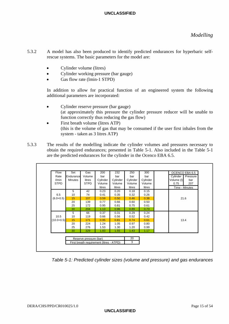
5.3.2 A model has also been produced to identify predicted endurances for hyperbaric self-rescue systems. The basic parameters for the model are:
• Cylinder volume (litres) • Cylinder working pressure (bar gauge) • Gas flow rate (lmin-1 STPD)
In addition to allow for practical function of an engineered system the following additional parameters are incorporated:
• Cylinder reserve pressure (bar gauge)
(at approximately this pressure the cylinder pressure reducer will be unable to function correctly thus reducing the gas flow)
• First breath volume (litres ATP) (this is the volume of gas that may be consumed if the user first inhales from the system - taken as 3 litres ATP)
5.3.3 The results of the modelling indicate the cylinder volumes and pressures necessary to
obtain the required endurances; presented in Table 5-1. Also included in the Table 5-1 are the predicted endurances for the cylinder in the Ocenco EBA 6.5.
Flow Set Gas 200 232 250 300Rate Endurance Volume bar bar bar bar Cylinder Pressurel/min Minutes litres Cylinder Cylinder Cylinder Cylinder Volume (l) bar
STPD STPD Volume Volume Volume Volume 0.75 207litres litres litres litres
5 42 0.23 0.20 0.18 0.156.5 10 74 0.41 0.35 0.32 0.26
(6.0+0.5) 15 107 0.59 0.50 0.46 0.3820 139 0.77 0.66 0.60 0.5025 172 0.95 0.81 0.75 0.6130 204 1.13 0.96 0.89 0.735 66 0.37 0.31 0.29 0.24
10.5 10 119 0.66 0.56 0.52 0.42(10.0+0.5) 15 171 0.95 0.81 0.74 0.61
20 224 1.24 1.05 0.97 0.8025 276 1.53 1.30 1.20 0.9930 329 1.83 1.55 1.43 1.17
203First breath requirement (litres - ATPD)
Reserve pressure (bar)
OCENCO EBA 6.5
Time - Minutes
21.6
13.4
Table 5-1: Predicted cylinder sizes (volume and pressure) and gas endurances
DERA/CHS/PPD/CR010025/1.0 Page 15 of 54 UNCLASSIFIED
UNCLASSIFIED
6 Design and modification 6.1 General 6.1.1 The design aim was to make a generic modification to a current compressed oxygen
closed-circuit system whilst meeting the European Personal Protective Equipment (PPE) directive and providing adequate performance at ambient pressures from 0.0 to 3.5 bar. The modification principle to be applicable to equivalent systems that may be produced by any manufacturer.
6.1.2 Current equipment (such as the Ocenco Incorporated EBA 6.5 self-contained self-
rescuer) have the following design elements for use at normobaric pressure that may provide the basis of a hyperbaric unit:
• Compressed oxygen supply (typically at a pressure of 200 to 250 bar gauge) • Pressure reducer • Demand valve to provide first breath oxygen supply • Constant mass flow of oxygen (typically 1.5 lmin-1) • Breathing circuit including counterlung and excess gas exhaust valve • Carbon dioxide removal system • Carrying case and harness
6.1.3 To create a unit suitable for use at hyperbaric pressures it must be able to:
• Provide the gas mixtures and flows identified in the operational envelopes above • Maintain adequate breathing performance with an increased breathing gas density • Have adequate gas and carbon dioxide absorbent capacity for the required
duration 6.1.4 The principle of the required generic modifications and specifics in respect of the Ocenco
Inc EBA 6.5 are as follows: 6.2 Gas supply - cylinder 6.2.1 The gas cylinder was required to contain oxygen in nitrogen gas mixtures (also called
Nitrox) with high oxygen content. Thus the cylinder (and the associated valve and reducers) had to be ‘oxygen compatible’, i.e. free from particulate and other (organic) contaminants that may combust with high-pressure oxygen.
6.2.2 The compressed oxygen cylinder was already compatible with high-pressure oxygen and
thus suitable for oxygen in nitrogen gas mixtures. The only modification required was to charge the cylinder with an appropriate gas mixture and to safety label the cylinder as containing the mixture; the label also specified the oxygen content.
Page 16 of 54 DERA/CHS/PPD/CR010025/1.0 UNCLASSIFIED

UNCLASSIFIED
Design and modification
6.3 Gas supply - principle of constant mass flow 6.3.1 To obtain a constant mass flow of gas into the apparatus (constant volume flow (STPD))
the principle of a ‘sonic orifice’ was applied. When gas is forced to flow through a small orifice under appropriate pressure conditions the maximum velocity of the gas molecules through the orifice is that of the velocity of sound (thus the term ‘sonic orifice’). The mass flow of gas under these conditions is then dependent upon the density of the gas (directly related to the driving pressure of the gas) and the size (cross sectional area) of the orifice. To obtain ‘sonic’ flow the pressure ratio across the orifice (driving pressure to exhaust pressure) should be maintained at a level greater than 2:1.
6.3.2 An advantage of a sonic orifice is that providing the pressure ratio is maintained at
greater than 2:1 the flow rate is independent of the exhaust pressure, i.e. in the case of a hyperbaric self-rescue device the ambient pressure of the breathing circuit.
6.3.3 However, the flow rate will be dependent on the driving pressure through the orifice. To
maintain a constant flow the driving pressure must be kept constant and independent of ambient pressure.
6.3.4 To provide for and allow adjustment between different flow rates either the driving
pressure or the orifice size may be changed. In semi-closed circuit diving apparatus both techniques have been applied with equal success. To produce a flexible proof of principle system based on the Ocenco Inc EBA 6.5 that would allow configuration for the operational envelopes described (and others as required) the specific modifications included fixing the regulator driving pressure and providing a variable orifice.
6.4 Gas supply - first stage regulator assembly 6.4.1 A schematic diagram of the Ocenco Inc EBA 6.5 gas supply regulator is presented at
Figure 6-1. 6.4.2 The first stage regulator assembly of the EBA 6.5 was designed to provide an output
pressure (from cylinder input pressure) of 8.5 bar above ambient pressure - the reducer being designed to track ambient pressure. The maximum proposed ambient pressure was 3.5 bar gauge (4.5 bar ambient). Thus to maintain a pressure ratio of greater than 2:1 the regulator output was required to be greater than 9.0 bar (2 x 4.5 bar). The first stage regulator internal spring was shimmed with metal washers to raise the output pressure from 8.5 bar gauge to a nominal 11.5 bar gauge.
DERA/CHS/PPD/CR010025/1.0 Page 17 of 54 UNCLASSIFIED

UNCLASSIFIED
Design and modification
6.4.3 To overcome the ambient pressure tracking of the EBA 6.5 first stage regulator, and thus provide a driving pressure to the orifice that was independent of exhaust pressure, the reference side of the regulator had to be fixed at atmospheric pressure. The vent hole in the regulator body was filled and an ‘O’ ring seal incorporated where the first stage body splits. A groove for the ‘O’ ring was machined at the base of the male thread. After significant engineering checks this made the first stage reference chamber gas tight with an enclosed pressure of atmospheric pressure (0.0 bar gauge).
6.4.4 A schematic diagram illustrating the modifications is presented at Figure 6-2. 6.5 Gas supply - second stage regulator 6.5.1 The EBA 6.5 second stage regulator includes both a demand-actuated valve (by user
inspiring with no gas in the breathing circuit - first breath capability) and a 1.5 lmin-1 (STPD) constant flow orifice (not adjustable). Both of these were applicable to a hyperbaric system although only part of the requirement for up to 10 lmin-1 (STPD) constant mass flow.
6.5.2 To provide the additional mass flow and allow it in a proof of principle system to be
adjustable, thereby covering all the described operational envelopes, a further gas injection port was required.
6.5.3 A gas injection port was made by a drilling into the top chamber of the second stage
regulator casing and inserting a compression fitting to take 1/8 inch Outside Diameter (OD) stainless steel piping.
6.6 Three-way manifold and variable orifice (metering valve) 6.6.1 To provide 11.5 bar gauge gas to both the existing and additional second stage regulator
injection ports a three-way manifold was manufactured; one of the threaded ports being connected to the first stage hose. This enabled the gas path to be bifurcated (Figure 6-2).
6.6.2 Additional piping was produced in 1/8 inch OD stainless steel. Piping ran from one of the
two remaining threaded delivery ports on the three-way manifold to the existing insert containing the demand system and 1.5 lmin-1 constant flow orifice connected to the second stage regulator top casing. A second pipe system was connected to a metering valve and then to the new injection port in the second stage regulator (Figure 6-2).
6.6.3 Typically ‘sonic orifices’ are engineered with a fixed cross section hole to give the
required flow. In production apparatus this is the ideal with the orifice being changed for each condition of use. For a generic modification and proof of principle system it was a variable orifice might be best achieved by using a metering valve. Although this does not give ideal ‘sonic orifice’ characteristics it has been used successfully in semi-closed circuit diving apparatus and was felt to be an acceptable solution.
Page 18 of 54 DERA/CHS/PPD/CR010025/1.0 UNCLASSIFIED
UNCLASSIFIED
Design and modification
6.6.4 With the three way manifold and metering valve it was possible to increase or decrease constant flow rate (STPD) of the regulator assembly by opening or closing the metering valve. It should be noted that when the metering valve was fully closed the assembly reverted to the initial designed constant gas delivery flow of 1.5 lmin-1 (STPD).
6.7 Apparatus carry case 6.7.1 The EBA 6.5 is designed with a sealed carry case to prevent dirt and contamination
affecting the apparatus during storage or deployment prior to use. If this case were taken into a pressurised tunnel the user would be unable to open the apparatus, as it would be effectively ‘vacuum packed’.
6.7.2 Vent holes were drilled into the external casing containing the apparatus to equalise the
internal pressure with ambient pressure. In a production system means of protecting the unit from the ingress of dirt and potential contaminants would have to be included.
6.7.3 The complete modified unit was re-packed into the existing carry case.
DERA/CHS/PPD/CR010025/1.0 Page 19 of 54 UNCLASSIFIED

UNCLASSIFIED
Design and modification
Figure 6-1: Standard regulator assembly
Page 20 of 54 DERA/CHS/PPD/CR010025/1.0 UNCLASSIFIED

UNCLASSIFIED
Design and modification
Figure 6-2: Modified regulator assembly
DERA/CHS/PPD/CR010025/1.0 Page 21 of 54 UNCLASSIFIED

UNCLASSIFIED
7 Unmanned testing 7.1 General 7.1.1 Testing of the modified unit was performed to confirm performance of two aspects:
• Modifications were operating as expected. • Hyperbaric breathing performance was compliant with PPE directive.
7.1.2 The unmanned tests were undertaken in the Life Support Systems Laboratory (LSSL) at
Alverstoke. This laboratory and associated pressure chamber was able to simulate apparatus being used in a range of operational hyperbaric and environmental conditions.
7.1.3 The supply gas for all tests was 40% oxygen balance nitrogen that complied with
Defence Standard (DEF STAN) 68-75/Issue 3 [13]. 7.2 Modified first stage regulator performance 7.2.1 The output (interstage) pressures from the modified first stage regulator (Modified Unit:
No 00030048) were determined in ambient pressures in the range 0.0 to 4.0 bar gauge. 7.2.2 The results (Figure 7-1) indicate that the modified reducer with ‘sealed’ first stage was
able to maintain a constant supply pressure of 11.2 bar in ambient pressures from 0.0 to 4.0 bar. This pressure was such that the required 2:1 pressure ratio for the ‘sonic orifice’ would be maintained throughout the expected operational range.
11.17 11.17 11.16 11.18
0.0
1.0
2.0
3.0
4.0
5.0
6.0
7.0
8.0
9.0
10.0
11.0
12.0
13.0
14.0
0.0 1.0 2.0 3.0 4.0
Ambient pressure – bar gauge
Inte
rsta
ge p
ress
ure
– ba
r gau
ge
Figure 7-1: Interstage pressure for ambient pressures from 0.0 to 4.0 bar gauge
Page 22 of 54 DERA/CHS/PPD/CR010025/1.0 UNCLASSIFIED

UNCLASSIFIED
Unmanned testing
7.3 Metering valve (sonic orifice) performance 7.3.1 The combined mass flow through the metering valve and integral mass flow orifice
(nominal 1.5 lmin-1) was monitored using a ‘bubble flow meter’ to give near absolute flow measurement at a range of ambient pressures. The temperature of the gas exhausting the flow meter was recorded and the flow rate corrected to STPD.
7.3.2 The flow was set at atmospheric pressure (0.0 bar gauge) to the nominal values required
for the described operational envelopes. The flow rate was then recorded with the complete regulator assembly at ambient pressures of 0.0 and 4.0 bar gauge.
7.3.3 The results of the tests (Figure 7-2) show that some reduction in STPD flow was
recorded, as may be expected with the non-ideal valve as opposed to a specific sonic orifice. However, the flow may be set at atmospheric pressure to obtain a flow rate within the tolerances of the modelling (± 0.5 lmin-1 STPD) over the whole pressure range 0.0 to 4.0 bar gauge. A more accurate system would be to calibrate the required flow at the expected pressure of use.
6.075.50
9.98
9.34
0.0
1.0
2.0
3.0
4.0
5.0
6.0
7.0
8.0
9.0
10.0
11.0
12.0
0.0 1.0 2.0 3.0 4.0 5.0
Ambient pressure – bar gauge
Flow rate:10 lmin-1 (nominal)
Flow rate:6 lmin-1 (nominal)
Fl
ow ra
te -
lmin
-1 (S
TPD
)
Figure 7-2: Flow rate (STPD) for ambient pressures of 0.0 and 4.0 bar gauge
DERA/CHS/PPD/CR010025/1.0 Page 23 of 54 UNCLASSIFIED

UNCLASSIFIED
Unmanned testing
7.4 Breathing performance 7.4.1 There are no specific standards for the breathing performance of hyperbaric self-rescue
systems. In order to demonstrate that the breathing performance of the modified system would comply with the requirements of the PPE directive two standards were applied to the unmanned tests:
• BS EN 400 - Self-contained closed-circuit breathing apparatus - Compressed
oxygen escape apparatus [2]. Applicable for closed (and semi-closed) circuit breathing apparatus for escape at atmospheric pressure.
• Norwegian Petroleum Directorate/Department of Energy (NPD/DEn) guidelines
[9]. Applicable for breathing apparatus to be used at pressure and under extreme environments.
The units used for respiratory pressures are different for each of the standards. BS EN 400 utilises mbar whereas the NPD/DEn guidelines use S.I. unit of Pascal’s (Pa). A summary of the pressure units used in this report is presented at appendix A.
7.4.2 A standard Ocenco EBA 6.5 (Unit No 00060147) was evaluated at normobaric pressure
(0.0 bar gauge) against the breathing performance requirements of BS EN 400. For comparison both the standard apparatus (Unit No 00060147) and the modified apparatus (Modified Unit: No 00030048) were tested at hyperbaric pressures in accordance with the NPD/DEn guidelines, and with reference to STANAG 1410-UD Standard unmanned test procedures for underwater breathing apparatus [14].
7.4.3 The apparatus were mounted in the LSSL hyperbaric chamber (Modified unit illustrated
in Figure 7-3) and evaluated in accordance with the above standards. The evaluation was conducted in air at a nominal temperature of 21 °C. The hyperbaric tests were performed at pressures of 0, 1.0, 2.0, 3.0, 3.5 and 4.0 bar gauge. The Lithium hydroxide absorbent canister supplied as standard by the manufacturer was also used for all the breathing performance tests.
Page 24 of 54 DERA/CHS/PPD/CR010025/1.0 UNCLASSIFIED

UNCLASSIFIED
Unmanned testing
Figure 7-3: Modified unit rigged for unmanned testing 7.4.4 Breathing performance was assessed using a breathing simulator at the nominal
ventilation rates shown in Table 7-1. Respiratory pressure was recorded throughout the breathing cycle and work of breathing was calculated. Inhalation and exhalation peak-to-end and peak-to-peak respiratory pressures were also determined. Figure 7-4 defines respiratory pressures and work of breathing in relation to the breathing loop for closed circuit apparatus.
Ventilation rate
(lmin-1) Tidal volume
(litres) Breaths per
minute 15.0 1.5 10 22.5 1.5 15 35.0 1.75 20 40.0 2.0 20 62.5 2.5 25 70.0 2.33 30 75.0 3.0 25 90.0 3.0 30
Table 7-1: Ventilation rates
DERA/CHS/PPD/CR010025/1.0 Page 25 of 54 UNCLASSIFIED

UNCLASSIFIED
Unmanned testing
Figure 7-4: Schematic of pressure-volume loop measurement; closed circuit 7.4.5 Ventilation rates for comparison with BS EN 400 were at Ambient Temperature and
Pressure Saturated (ATPS), for comparison with the NPD/DEn guidelines they were corrected to Body Temperature Pressure Saturated (BTPS).
7.4.6 Breathing performance - comparison of Standard unit with BS EN 400 [2]: 7.4.6.1 The requirements of BS EN 400, 1993 are:
‘Paragraph 5.25.6.1 Breathing resistance at 35 l/min (b) For the apparatus with a rated duration of more than 30 min,
the sum of the inhalation and exhalation resistances shall not exceed 13 mbar and the maximum individual breathing resistance for inhalation or exhalation shall not exceed 7,5 mbar.
Paragraph 5.25.6.2 Breathing resistance at 70 l/min For apparatus of all rated durations, the breathing resistance for
inhalation as well as for exhalation shall not exceed 20 mbar.’ 7.4.6.2 The results of the tests on the Standard unit are presented in Table 7-2.
Ventilation Rate (lmin-1 ATPS)
Exhale Respiratory Pressure
Inhale Respiratory Pressure
Peak-To-Peak Respiratory Pressure
35.4 4.8 mbar (0.48 kPa)
- 7.3 mbar (- 0.73 kPa)
7.6 mbar (0.76 kPa)
70.3 10.5 mbar (1.05 kPa)
- 11.3 mbar (- 1.13 kPa)
16.7 mbar (1.67 kPa)
Table 7-2: Breathing performance of standard EBA 6.5 unit (BS EN 400)
Page 26 of 54 DERA/CHS/PPD/CR010025/1.0 UNCLASSIFIED

UNCLASSIFIED
Unmanned testing
7.4.6.3 It can be seen that although the Standard Ocenco EBA 6.5 self rescue system is not ‘CE Marked’ to BS EN 400 it fulfils the atmospheric pressure requirements in respect of breathing performance.
7.4.7 Breathing performance - comparison of standard and modified unit with NPD/DEn
guidelines [9]: 7.4.7.1 Comparison between the breathing performance of the Standard unit (Unit No 00060147,
Flow rate: 1.5 lmin-1) and the Modified unit (Unit No 00030048) are presented below:
• Figure 7-5, Work of breathing • Figure 7-6, Peak to end respiratory pressure • Figure 7-7, Peak to peak respiratory pressure
7.4.7.2 It can be seen in Figures 7-5, 7-6, and 7-7 that there was no appreciable degradation in
performance between the standard unit and the modified unit with increased flow rates. As would be expected with and increase in ambient pressure and associated increase in respiratory gas density there was a degradation in performance with raised pressure.
7.4.7.3 Ideally breathing apparatus should comply with the ‘preferred’ NPD/DEn guideline to
give the greatest benefit to the user of the apparatus. However, the performance of the both the standard and modified unit do comply with the requirement of the ‘maximum’ guideline at ventilation rates up to 70 lmin-1 and ambient pressures up to and including 3.5 bar gauge.
7.4.7.4 It was felt that as the modified unit complied with the ‘maximum’ limit of the NPD/DEn
guidelines at the maximum pressure of intended use, it was acceptable in respect of breathing performance for the unit to proceed to manned evaluation.
DERA/CHS/PPD/CR010025/1.0 Page 27 of 54 UNCLASSIFIED

UNCLASSIFIED
Unmanned testing
Standard unit (No 00060147) 1.5 lmin-1 flow rate
0.0
0.5
1.0
1.5
2.0
2.5
3.0
3.5
4.0
4.5
5.0
0 10 20 30 40 50 60 70 80 90 100 110
Ventilation Rate (lmin-1 BTPS)
0.0 bar g1.0 bar g2.0 bar g3.0 bar g3.5 bar g4.0 bar g
DEn Guidelines
Maximum limit
Preferred limit
Modified unit (No 00030048) 6 lmin-1 flow rate
0.0
0.5
1.0
1.5
2.0
2.5
3.0
3.5
4.0
4.5
5.0
0 10 20 30 40 50 60 70 80 90 100 110
Ventilation Rate (lmin -1 BTPS)
0.0 bar g1.0 bar g2.0 bar g3.0 bar g3.5 bar g4.0 bar g
DEn Guidelines
Maximum limit
Preferred limit
Modified unit (No 00030048) 10 lmin-1 flow rate
0.0
0.5
1.0
1.5
2.0
2.5
3.0
3.5
4.0
4.5
5.0
0 10 20 30 40 50 60 70 80 90 100 110
Ventilation Rate (lmin-1 BTPS)
0.0 bar g1.0 bar g2.0 bar g3.0 bar g3.5 bar g4.0 bar g
DEn Guidelines
Maximum limit
Preferred limit
Figure 7-5: Breathing performance, comparison of work of breathing
Page 28 of 54 DERA/CHS/PPD/CR010025/1.0 UNCLASSIFIED

UNCLASSIFIED
Unmanned testing
Standard unit (No 00060147) 1.5 lmin-1 flow rate
-3.0
-2.5
-2.0
-1.5
-1.0
-0.5
0.0
0.5
1.0
1.5
2.0
2.5
3.0
0 10 20 30 40 50 60 70 80 90 100 110
Ventilation Rate (lmin-1 BTPS)
0.0 bar g
1.0 bar g
2.0 bar g
3.0 bar g
3.5 bar g
4.0 bar g
Maximum limit
Preferred limit
Preferred limit
Maximum limit
Modified unit (No 00030048) 6 lmin-1 flow rate
-3.0
-2.5
-2.0
-1.5
-1.0
-0.5
0.0
0.5
1.0
1.5
2.0
2.5
3.0
0 10 20 30 40 50 60 70 80 90 100 110
Ventilation Rate (lmin-1 BTPS)
0.0 bar g
1.0 bar g
2.0 bar g
3.0 bar g
3.5 bar g
4.0 bar g
Maximum limit
Preferred limit
Preferred limit
Maximum limit
Modified unit (No 00030048) 10 lmin-1 flow rate
-3.0
-2.5
-2.0
-1.5
-1.0
-0.5
0.0
0.5
1.0
1.5
2.0
2.5
3.0
0 10 20 30 40 50 60 70 80 90 100 110
Ventilation Rate (lmin-1 BTPS)
0.0 bar g
1.0 bar g
2.0 bar g
3.0 bar g
3.5 bar g
4.0 bar g
Maximum limit
Preferred limit
Preferred limit
Maximum limit
Figure 7-6: Breathing performance, comparison of peak-to-end respiratory pressure Standard unit (No 00060147) 1.5 lmin-1 flow rate
DERA/CHS/PPD/CR010025/1.0 Page 29 of 54 UNCLASSIFIED

UNCLASSIFIED
Unmanned testing
0.0
0.5
1.0
1.5
2.0
2.5
3.0
3.5
4.0
4.5
5.0
5.5
6.0
0 10 20 30 40 50 60 70 80 90 100 110
Ventilation Rate (lmin-1 BTPS)
0.0 bar g
1.0 bar g
2.0 bar g
3.0 bar g
3.5 bar g
4.0 bar g
Maximum limit
Preferred limit
Modified unit (No 00030048) 6 lmin-1 flow rate
0.0
0.5
1.0
1.5
2.0
2.5
3.0
3.5
4.0
4.5
5.0
5.5
6.0
0 10 20 30 40 50 60 70 80 90 100 110
Ventilation Rate (lmin-1 BTPS)
0.0 bar g
1.0 bar g
2.0 bar g
3 0 bar g
3.5 bar g
4.0 bar g
Maximum limit
Preferred limit
Modified unit (No 00030048) 10 lmin-1 flow rate
0.0
0.5
1.0
1.5
2.0
2.5
3.0
3.5
4.0
4.5
5.0
5.5
6.0
0 10 20 30 40 50 60 70 80 90 100 110
Ventilation Rate (lmin-1 BTPS)
0.0 bar g
1.0 bar g
2.0 bar g
3.0 bar g
3.5 bar g
4.0 bar g
Maximum limit
Preferred limit
Figure 7-7: Breathing performance, comparison of peak-to-end respiratory pressure
Page 30 of 54 DERA/CHS/PPD/CR010025/1.0 UNCLASSIFIED

UNCLASSIFIED
Unmanned testing
7.5 Apparatus endurance (carbon dioxide absorbent canister) 7.5.1 Absorbent materials and canisters 7.5.1.1 The Ocenco EBA 6.5 standard unit is supplied with an absorbent canister that contains
granular lithium hydroxide (nominally 0.64 kg). A few replacement absorbent canisters were obtain from the manufacturer to conduct testing on the modified unit - however, due to difficulties with delivery times (primarily to transatlantic supply and customs) limited tests were undertaken on the lithium canisters.
7.5.1.2 Soda lime has been successfully used for many years in diving apparatus at hyperbaric
pressures. In order to conduct a range of canister endurance tests at hyperbaric pressures a standard EBA 6.5 absorbent canister was disassembled and the lithium hydroxide removed (Figure 7-8). The canister could then be refilled with soda lime for subsequent tests. In addition to this a re-fillable canister for use with soda lime was made at DERA for testing (this canister could not be fitted into the original carry case and was only used for one test).
Figure 7-8: Component parts of disassembled absorbent canister 7.5.1.3 The soda lime used for the additional tests was that used in RN re-breathing diving
apparatus and in accordance with DEF STAN 68-166/1, Grade D [15]. The soda lime was from Batch Numbers: 78D Feb99, 85D Jun99 and 88D Jun99.
DERA/CHS/PPD/CR010025/1.0 Page 31 of 54 UNCLASSIFIED

UNCLASSIFIED
Unmanned testing
7.5.2 Endurance tests 7.5.2.1 The modified apparatus was mounted vertically in the LSSL hyperbaric chamber
(Figure 7-3) and the canister endurance evaluated in air at a nominal temperature of 21 °C. The ventilation rate for the tests was 40 lmin-1 (20 breaths per minute, Tidal volume 2.0 litres) ATPS with carbon dioxide injected into the exhalation side of the breathing simulator at a flow rate of 1.6 lmin-1 STPD. The exhaled gas from the breathing simulator was also heated and humidified to simulate expired gas.
7.5.2.2 The carbon dioxide content of the gas in the inhale hose of the apparatus was monitored
in real time using a mass spectrometer and recorded. The endurance of the apparatus was taken as the time for the inspired partial pressure of carbon dioxide to obtain a level of 0.5 kPa (5 mbar).
7.5.2.3 Comparative endurance tests between the standard lithium hydroxide canister and the
canister packed with soda lime to DEF STAN 68-166/1 were conducted at atmospheric pressure (0.0 bar gauge). Additional tests to identify the endurance of the system with soda lime at hyperbaric pressure were conducted at 2.0 and 3.5 bar gauge with flow rates of 6 and 10 lmin-1 respectively
7.5.2.4 The tests conducted and resultant canister endurance’s (time to 0.5 kPa carbon dioxide in
the inhalation hose) are presented in Table 7-3.
Test reference
Apparatus unit Canister CO2
absorbent
Mass CO2 absorbent
(g)
Gas flow rate
lmin-1
Time to 0.5 kPa CO2
(minutes)
Pressure (bar
gauge) SR3 Standard DERA
refillable Soda lime 1052.2 106 0.0
SR9 Standard Manuf. Can 2 Lithium Nominally 640
28 (estimated)
0.0
SR10 Standard Manuf. Can 3 Lithium Nominally 640
34 0.0
SR11 Standard Modified Soda lime 975.6
1.5
81 0.0 SR12 Modified Modified Soda lime 979.9 6 92 2.0 SR13 Modified Modified Soda lime 977.2 10 87 3.5 SR16 Modified Modified Soda lime 975.6 10 65 3.5 SR17 Modified Modified Soda lime 973.9 6 83 2.0
Table 7-3: Carbon dioxide absorbent canister - endurance tests
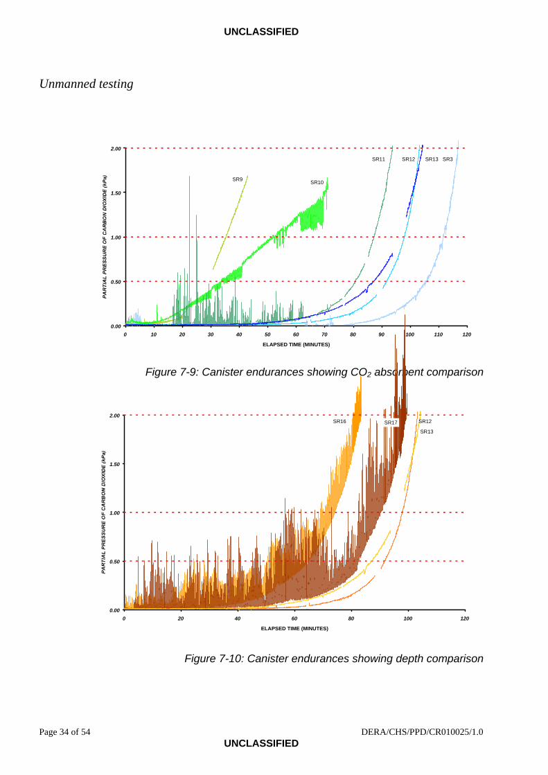
7.5.2.5 Graphical presentation and comparison of the endurance tests are presented in
Figures 7-9 and 7-10. Note: Transient carbon dioxide peaks during maximum flow through the absorbent canister are present on several of the tests.
7.5.2.6 During the endurance tests additional checks were made on the breathing performance of
the apparatus. No change in performance was observed when using soda lime as opposed to the lithium hydroxide.
Page 32 of 54 DERA/CHS/PPD/CR010025/1.0 UNCLASSIFIED

UNCLASSIFIED
Unmanned testing
7.5.2.7 The endurance results (Table 7-3) show that under all conditions tested the apparatus was able to support an operational endurance of 30 minutes. Surprisingly the soda lime demonstrated significant improvements in endurance over the lithium hydroxide absorbent. The soda lime absorbent/canister system was also found under all pressure and flow conditions to be able to support an operational duration considerably greater than 30 minutes and the gas endurance of the apparatus (and proposed apparatus configurations - appendix D).
7.5.2.8 It is felt that the system may be used with either lithium hydroxide or soda lime,
whatever absorbent was being considered it should undergo further testing under the proposed conditions of use. However, for expediency it is felt that the manufacturers canister (that will fit into the carry case) filled with soda lime that complies with DEF STAN 68-166/1 would be most appropriate for future manned evaluation of the apparatus.
DERA/CHS/PPD/CR010025/1.0 Page 33 of 54 UNCLASSIFIED
UNCLASSIFIED
Unmanned testing
0.00
0.50
1.00
1.50
2.00
0 10 20 30 40 50 60 70 80 90 100 110 12
ELAPSED TIME (MINUTES)
0
SR3
SR9 SR10
SR11 SR12 SR13
Figure 7-9: Canister endurances showing CO2 absorbent comparison
0.00
0.50
1.00
1.50
2.00
0 20 40 60 80 100 120
ELAPSED TIME (MINUTES)
SR13
SR17 SR12SR16
Figure 7-10: Canister endurances showing depth comparison
Page 34 of 54 DERA/CHS/PPD/CR010025/1.0 UNCLASSIFIED

UNCLASSIFIED
8 Discussion 8.1 The review of existing self-rescue systems identified that many techniques have been
used to produce self-rescue devices. Although compressed oxygen closed-circuit systems are increasingly becoming scarce (with several manufacturers discontinuing production) units were identified for generic modification. It would be desirable, with a requirement for hyperbaric units, to encourage manufacturers to re-consider production of closed-circuit oxygen systems and a semi-closed circuit hybrid for hyperbaric self-rescue.
8.2 The programme has shown by modelling and production of a proof of principle system
that with minimum modification, a currently available closed-circuit oxygen system (Ocenco EBA 6.5) may be converted into a semi-closed circuit hyperbaric self-rescue apparatus. The apparatus configuration such that it is able to maintain the breathing gas within acceptable physiological parameters in respect of inspired partial pressures of oxygen and carbon dioxide.
8.3 It should not be considered that the only means of producing a hyperbaric system are by
modification of the Ocenco EBA 6.5 apparatus. The system was used for ‘proof of principle’. The conversion of the gas supply from oxygen to oxygen in nitrogen mixtures (Nitrox) coupled with a constant mass flow reducer to give the required mass flows should be generic and easily applicable to other closed-circuit oxygen systems.
8.4 Three ‘operational envelopes’ were identified for use with hyperbaric self-rescue system
configurations (Figures 5-2, 5-3 and 5-4) that would maintain inspired PO2 in the range 0.2 to 1.8 bar when the user is either at rest or performing hard work. Although the required ambient pressure range may be covered by only two of the three envelopes (Envelope 1 - Figure 5-2 and Envelope 3 - Figure 5-4) significant advantages in endurance (due to a flow of only 6 lmin-1 rather than 10 lmin-1) may be obtained using Envelope 2 (Figure 5-3) in the pressure range 1.5 to 2.0 bar gauge. The proposed ‘operational envelopes’ and associated gas mixtures, flow rates and cylinder sizes are presented in appendix D.
8.5 It is not only the inspired partial pressure of oxygen that needs to be considered when
generically modifying a unit for use at hyperbaric pressure. The breathing performance in respect of work of breathing and respiratory pressures and apparatus endurance should also be considered.
8.6 The ‘proof of principle’ system was un-manned tested at hyperbaric pressures up to
3.5 bar gauge using test and acceptance criteria for diving breathing apparatus (traditionally the only breathing systems used at hyperbaric pressures). Tests showed that the unit complied with both the current atmospheric pressure breathing performance requirement (BS EN 400 [2]) and the diving apparatus requirements (NPD/DEn guidelines [9]). However, the hyperbaric performance was not ideal and improvement would be recommended.
8.7 Endurance of an apparatus is dependent upon the absorbent canister endurance and the
gas flow and gas supply aspects of the apparatus. Testing of the ‘proof of principle’
DERA/CHS/PPD/CR010025/1.0 Page 35 of 54 UNCLASSIFIED

UNCLASSIFIED
Discussion
absorbent system at hyperbaric pressures showed that a canister filled with soda lime absorbent was easily able to fulfil the requirements of a hyperbaric system. Additional work, possibly as part of a manned testing programme, would be required to demonstrate the use of lithium hydroxide absorbent at hyperbaric pressures.
8.8 The gas endurance has been addressed by modelling and calculation (it was not
considered that practical un-manned testing would provide additional data over the calculated endurances). Gas endurance of the modified ‘proof of principle system complies with the aim of 15 minutes minimum endurance with a flow of 6.0 lmin-1 but falls short of the requirement with an endurance of 13.4 minutes with a flow of 10.0 lmin-1 (Table 5-1).
8.9 System configurations that are expected to be practical in use, meet the minimum
required endurance (15 minutes) and approach the 30 minute preferred endurance are presented in appendix D. The configurations have been identified by considering pragmatic cylinder sizes and a minimum number of gas mixture and flow permutations.
8.10 The work programme used experience gained from developing and testing diving
systems to provide criteria against which to produce and test a ‘proof of principle’ apparatus. To facilitate development of ‘production’ systems and enable them to be proven as fit for purpose in respect of the PPE directive a requirement for a ‘specification’ for hyperbaric self-rescue systems has been identified. It is proposed that the criteria used for this work be used as the basis of a future specification.
8.11 Unmanned testing of breathing apparatus is only considered to be part of a validation
process. DERA Alverstoke have identified and proposed a procedure for the testing and evaluation of diving breathing apparatus [16]. It is felt that this procedure is equally applicable to hyperbaric self-rescue apparatus and indeed other respiratory protective apparatus.
8.12 Following the proposed procedure [16] manned trials under hyperbaric conditions should
be considered to demonstrate the following aspects of the apparatus:
• Ergonomic aspects for use under hyperbaric conditions. • Graded exercise test [16] to demonstrate breathing performance, inspired gas
temperature and inspired PO2 whilst a subject is at rest and performing hard work. • Apparatus endurance considering gas requirements (likely to be greater manned
than unmanned due to leakage) and carbon dioxide absorbent endurance (this could also consider the aspects of soda lime and lithium hydroxide).
• Performance at pressures up to and including 3.5 bar gauge (this to address testing in each of the three proposed operational envelopes).
Page 36 of 54 DERA/CHS/PPD/CR010025/1.0 UNCLASSIFIED

UNCLASSIFIED
9 Summary 9.1 A range of techniques has been used to provide self-rescue breathing apparatus for use
during normobaric tunnelling operations. Tunnelling work may also be conducted at elevated pressures up to 3.5 bar gauge.
9.2 The review of existing self-rescue systems identified that many techniques have been
used to produce self-rescue devices. These systems are not appropriate for these operations due to limited endurance and the toxic effect of oxygen at elevated inspired partial pressure.
9.3 A mathematical model has been developed to predict the inspired partial pressure of
oxygen within a modified closed-circuit self-rescue system at hyperbaric pressures. The model considers the percentage of oxygen in the gas mixture, gas flow rate, work rate of the user and gas endurance.
9.4 Use of the model has allowed three ‘operational envelopes’ for hyperbaric self rescue
systems to be identified (appendix D). 9.5 A proof of principle semi-closed circuit hyperbaric self-rescue apparatus was developed
for use in the three proposed ‘operational envelopes’. The system was produced by minimal modification to a currently available closed-circuit oxygen system (Ocenco Inc EBA 6.5). The modifications may also be generically applied to other closed-circuit compressed oxygen systems.
9.6 It would be desirable, with a requirement for hyperbaric units, to encourage
manufacturers to re-consider production of closed-circuit oxygen systems and a semi-closed circuit hybrid for hyperbaric self-rescue.
9.7 Un-manned testing showed that the proof of principle unit complied with both the current
atmospheric pressure breathing performance requirement (BS EN 400 [2]) and the diving apparatus requirements (NPD/DEn guidelines [9]). It also demonstrated that the absorbent system would have adequate endurance under hyperbaric conditions.
9.8 To facilitate development of ‘production’ systems and enable them to be proven as fit for
purpose in respect of the PPE directive a requirement for a ‘specification’ for hyperbaric self-rescue systems has been identified. It is proposed that the criteria used for this work be used as the basis of a future specification.
9.9 Hyperbaric self-rescue system configurations that are expected to be practical in use,
meet the minimum required endurance (15 minutes) and approach the 30 minute preferred endurance, are presented in appendix D.
9.10 Manned trials should be conducted on a proof of principle self-rescue system under
hyperbaric conditions.
DERA/CHS/PPD/CR010025/1.0 Page 37 of 54 UNCLASSIFIED

UNCLASSIFIED
10 References
1 Useful facts in relation to the Protective Personal Equipment (PPE) Directive 89/686/EEC. European Commission, 2000. ISBN 92-828-8400-7.
2 BS EN 400: 1993. Respiratory protective devices for self-rescue - Self-contained
closed-circuit breathing apparatus - Compressed oxygen escape apparatus - Requirements, testing marking.
3 BS EN 401: 1993. Respiratory protective devices for self-rescue - Self-contained
closed-circuit breathing apparatus - Chemical oxygen (KO2) escape apparatus - Requirements, testing marking.
4 BS EN 402: 1993. Respiratory protective devices for escape - Self-contained
open-circuit compressed air breathing apparatus with full face mask or mouthpiece assembly.
5 BS EN 1061: 1997 Respiratory protective devices for self-rescue - Self-contained
closed-circuit breathing apparatus - Chemical oxygen (NaClO3) escape apparatus - Requirements, testing marking.
6 BS EN 1146: 1997 Respiratory protective devices for self-rescue - Self-contained
open-circuit compressed air breathing apparatus incorporating a hood (compressed air escape apparatus with hood) - Requirements, testing marking.
7 BENNETT, P.B. and ELLIOTT, D.H. Editors. The physiology and medicine of
diving. 4th Edition, W B Saunders, London, 1993, ISBN 0-7020-1589-X. 8 DERA Alverstoke proposal to investigate use of self-rescue devices at increased
hyperbaric pressure. DERA/CHS/5.05/3/12, January 1999. 9 Norwegian Petroleum Directorate/Department of Energy. Guidelines for
evaluation of breathing apparatus for use in manned underwater operations in the petroleum activities. 1991. ISBN 82-7257-308-3.
10 BR 2806 Diving Manual. CINCFLEET/FSAG/P2806/2. 11 BS EN 403: 1993. Filtering respiratory protective devices with hood for self-
rescue from fire. 12 ANTHONY, T.G., SCANDLING, L.M.P. and WILLIAMS, J. Evaluation of the
performance of oxygen candles at increased ambient pressure. ARE(ESD) TM88702, June 1988.
13 Compressed breathing gases for diving and life support equipment. DEF STAN
68-75/Issue 3, 30 June 1995.
Page 38 of 54 DERA/CHS/PPD/CR010025/1.0 UNCLASSIFIED

UNCLASSIFIED
References
14 STANAG 1410-UD (Edition 1) (Ratification Draft) - Standard unmanned test procedures for underwater breathing apparatus.
15 Interim DEF STAN 68-166/Issue 1, 8 July 1993. Soda lime, Grades D, L and S. 16 DOBBINS, T.D., GILBERT, M.J., GAY, L.A. and ANTHONY, T.G. Procedures
for the evaluation of diving life support systems. DERA/CHS/PPD/CR980144/1.0, March 1999.
DERA/CHS/PPD/CR010025/1.0 Page 39 of 54 UNCLASSIFIED

UNCLASSIFIED
11 Acknowledgements 11.1 The authors would like to acknowledge the assistance of Bob Gould and Arran Fisher of
the DERA Alverstoke Life Support Systems Laboratory in conducting the unmanned tests and ‘Alby’ Hall, Jim Nicholson and Simon Bradley for engineering support. We would also like to thank Mr Donald Lamont of the HSE and members of the Compressed Air Working Group (CAWG) for guidance in respect of the conditions and requirements of self-rescue in pressured tunnelling operations.
Page 40 of 54 DERA/CHS/PPD/CR010025/1.0 UNCLASSIFIED

UNCLASSIFIED
12 List of abbreviations
ATP - Ambient Temperature and Pressure
ATPS - Ambient Temperature and Pressure Saturated
BR - Book of Reference
BS - British Standard
BTPS - Body Temperature and Pressure Saturated
CAWG - Compressed Air Working Group
CE - European Commission
CHS - Centre for Human Sciences
CNS - Central Nervous System
DEF STAN - Defence Standard
DEn - Department of Energy
DERA - Defence Evaluation and Research Agency
EBA - Emergency Breathing Apparatus
EC - European Community
EN - European Norm
HSE - Health and Safety Executive
LSSL - Life Support Systems Laboratory
OD - Outside Diameter
NPD - Norwegian Petroleum Directorate
PPD - Protection and Performance Department
PPE - Personal Protective Equipment
RN - Royal Navy
RSU - Research Support Unit
STANAG - Standardisation Agreement (NATO)
STP - Standard Temperature and Pressure
STPD - Standard Temperature and Pressure Dry
UK - United Kingdom
PO2 - Partial pressure of oxygen
DERA/CHS/PPD/CR010025/1.0 Page 41 of 54 UNCLASSIFIED

UNCLASSIFIED
This page is intentionally blank
Page 42 of 54 DERA/CHS/PPD/CR010025/1.0 UNCLASSIFIED

UNCLASSIFIED
A Pressure units A.1 Many units of pressure may be used in the context of respiratory protective devices and
work at hyperbaric pressure. A.2 The basic unit of pressure used in this report is ‘bar’. This has been used in two ways for
the following: A.2.1 Absolute unit - bar (also known as bar absolute); this unit has been used for:
• Atmospheric pressure (taken to be 1.013 bar).
• Inspired partial pressure of a gas. A.2.2 Comparative unit - bar gauge (this equates to the pressure greater than atmospheric
pressure, i.e. 0 bar gauge is atmospheric pressure), these units are used for:
• The pressure to which a tunnel worker is subjected - bar gauge.
• Cylinder and equipment pressure - bar gauge. A.3 Additional units of pressure that may be encountered in respiratory equipment and work
at pressure are:
• Pounds per Square Inch (psi) (This may also be used as absolute or gauge units) − Pounds per Square Inch absolute (psia) − Pounds per Square Inch gauge (psig)
• Depth measured in metres (m), where 10 m is equivalent to a pressure of
1.000 bar ambient (this assumes a water density of 1.01972 at 4 °C).
• Units used for presenting respiratory pressures:
− Millibar (mbar) − KiloPascal (kPa)
Where 1 kPa = 10 mbar
A.4 Conversion factors - related to bar:
1.0 bar or bar gauge is equivalent to:
• 14.5 psi • 10 m
DERA/CHS/PPD/CR010025/1.0 Page 43 of 54 UNCLASSIFIED

UNCLASSIFIED
This page is intentionally blank
Page 44 of 54 DERA/CHS/PPD/CR010025/1.0 UNCLASSIFIED

UNCLASSIFIED
B Existing apparatus B.1 Manufacturer: CSE Corporation
600 Seco Road Monroeville, Pennsylvania 15146-1428 Tel: 00 1 (412) 856 9200 Fax: 00 1 (412) 856 9203
B.1.1 Equipment: CSE SR-100 (chemical oxygen) B.2 Manufacturer: Draeger Limited
Ullswater Close Kitty Brewster Industrial Estate Blyth Northumberland NE24 4RG Tel: +44 (0) 1670 352891 Fax: +44 (0) 1670 356266 Customer Enquiries and Sales
B.2.1 Equipment 1: Oxy K-50 Self-Rescuer (chemical oxygen) B.2.2 Equipment 2: Oxy K-30 Self-Rescuer (chemical oxygen) B.2.3 Equipment 3: RapidAir Emergency Escape BA (compressed air) B.2.4 Equipment 4: Saver PP10 Escape Set (compressed air) B.3 Manufacturer: Fenzy SA
Bacou UK Unit 8 - Stuart Close Penarth Road Cardiff CF1 7QF - United Kingdom Tel: +44 (0) 1222 237897 (5 lines) Fax: +44 (0) 1222 237862
B.3.1 Equipment 1: Fenzy Biocell 1 (chemical oxygen) B.3.2 Equipment 2: Fenzy Air 5500 Mini (compressed air) B.3.3 Equipment 3: Fenzy Biosafe (compressed air)
DERA/CHS/PPD/CR010025/1.0 Page 45 of 54 UNCLASSIFIED

UNCLASSIFIED
B - Existing apparatus
B.4 Manufacturer: Interspiro Limited 7 Hawksworth Road Central Park, Telford Shropshire TF2 9TU Tel: +44 (0) 1952 200190 Fax: +44 (0) 1952 299805
B.4.1 Equipment: Interspiro Spiroscape (compressed air) B.5 Manufacturer: Life Support Engineering Limited
Robell Way Storrington Sussex, RH20 3DN Tel: +44 (0) 903 742322 Fax: +44 (0) 903 745923
B.5.1 Equipment: Talisman SCSR (compressed oxygen) - [Obsolete] B.6 Manufacturer: MSA (Britain) Limited
East Shawhead Coatbridge ML5 4TD - Scotland Tel: +44 (0) 1236 702223 Fax: +44 (0) 1236 440881
B.6.1 Equipment 1: SSR30/100 (chemical oxygen) B.6.2 Equipment 2: SSR16N (chemical oxygen) B.6.3 Equipment 3: SSR30/100B (chemical oxygen) B.6.4 Equipment 4: SSR90 (chemical oxygen) B.6.5 Equipment 5: SSR120 (chemical oxygen) B.6.6 Equipment 6: SSR UW (chemical oxygen) B.6.7 Equipment 7: S15 (chemical oxygen) B.6.8 Equipment 8: SAR 30 (chemical oxygen) B.6.9 Equipment 9: SSR30 BS (chemical oxygen)
Page 46 of 54 DERA/CHS/PPD/CR010025/1.0 UNCLASSIFIED

UNCLASSIFIED
B - Existing apparatus
B.7 Manufacturer: North Safety Products Siebe Gorman & Co Limited Avondale Way, Cwmbran Gwent NP44 1TS United Kingdom Tel: +44 (0) 1633 861211 Fax: +44 (0) 1633 872759
B.7.1 Equipment 1: North Star EEBA (compressed air) B.7.2 Equipment 2: Aurora EEBA (compressed air) B.7.3 Equipment 3: MO30 (compressed oxygen) - [Obsolete] B.8 Manufacturer: Ocenco Incorporated
10225 82nd Avenue Pleasant Prairie WI 53158-5801 USA Tel: 00 1 (262) 947 9000 Fax: 00 1 (262) 947 9020 www.ocenco-eebd.com
B.8.1 Equipment 1: M-20.2 (compressed oxygen) B.8.2 Equipment 2: EBA 6.5 (compressed oxygen) B.9 Manufacturer: Protector Technologies Europe
Matterson House Ash Road Aldershot Hants GU12 4DE Tel: +44 (0) 1252244141 Fax: +44 (0) 1252 231921
B.9.1 Equipment: RDSR-10 (compressed air)
DERA/CHS/PPD/CR010025/1.0 Page 47 of 54 UNCLASSIFIED
UNCLASSIFIED
B - Existing apparatus
B.10 Manufacturer: Sabre Breathing Apparatus Protector Technologies Group Matterson House, Ash Road Aldershot Hampshire GU12 4DE, UK Tel: +44 (0) 1252 344141 Fax: +44 (0) 1252 321921
B.10.1 Equipment 1: ELSA 2000 Escape Set (compressed air) B.10.2 Equipment 2: ELSA Sprint Escape Set (compressed air) B.11 Manufacturer: Scott Aviation
225 Erie Street Lancaster New York 14086 USA Tel: 00 1 (716) 683 5100 Fax: 00 1 (716) 681 1089
B.11.1 Equipment: 15 minute EEBD (chemical oxygen) B.12 Manufacturer: Chapman & Smith Ltd - Safir Protection
Safir Works, East Hoathly Lewes East Sussex, BN8 6EW Tel: +44 (0) 1825 840323 Fax: +44 (0) 1825 840827
B.12.1 Equipment: Sekur Air 600-PI Escape Apparatus (compressed air) B.13 Manufacturer: Semco Ltd
Wintonlea Industrial Estate Monument Way West Woking Surrey GU21 5EN Tel: +44 (0) 1483 757200 Fax: +44 (0) 1483 740795
B.13.1 Equipment 1: Head 10 Carry Case (CC) (chemical oxygen)
Page 48 of 54 DERA/CHS/PPD/CR010025/1.0 UNCLASSIFIED

UNCLASSIFIED
C Derivation of steady state equation C.1 System configuration
Breathing Bag
→ Excess gas exhausted Flow rate
(V, lmin-1) Oxygen %
(%O2)
Fraction Oxygen
↓ Oxygen consumed
VO2
Gas entering bag,
C.2 Derivation
Breathing bag at ambient pressure, P (bar absolute)
Total volume gas entering system in one minute, V (litre - STPD)
Volume oxygen entering system in one minute (litre - STPD),
= V * (%O2 / 100)
Volume oxygen consumed in one minute, VO2 (litre - STPD)
Fraction of oxygen in system (steady state based on one minute), FO2
Volume of oxygen entered - Volume oxygen consumed FO2 =
Volume gas entered - Volume oxygen consumed
(V * (%O2 / 100)) - VO2FO2 =
V - VO2
Partial pressure of oxygen in system (inspired), PO2 (bar absolute)
(V * (%O2 / 100)) - VO2PO2 =
V - VO2
* P
DERA/CHS/PPD/CR010025/1.0 Page 49 of 54 UNCLASSIFIED

UNCLASSIFIED
This page is intentionally blank
Page 50 of 54 DERA/CHS/PPD/CR010025/1.0 UNCLASSIFIED

UNCLASSIFIED
D Proposed specification D.1 Technical specification D.1.1 Three operational envelopes are proposed:
Envelope 1: 0.0 to 1.5 bar gauge
Envelope 2: 1.0 to 2.0 bar gauge
Envelope 3: 1.5 to 3.5 bar gauge D.1.2 The proposed specification in respect of gas mixtures, flows and cylinder sizes for
hyperbaric self-rescue systems to cover the proposed operational envelopes are presented in Table D-1.
D.1.3 The specification in Table D-1 allows for the cylinder pressure to fall to 20 bar (where
the reduce would still function correctly) and for the user to take a ‘first breath’ of 3 litres ATP.
Operational Minimum Maximum Mixture Flow Cylinder CylinderEnvelope Pressure Pressure Oxygen Rate volume pressure
bar(g) bar(g) % l/min litres bar
1 0.0 1.5 65 6.0 0.75 250
2 1.0 2.0 60 6.0 0.75 250
3 1.5 3.5 40 10.0 0.75 250
203First breath requirement (litres)
26.5
26.5
16.4
EnduranceMax Pressures
Minutes
Reserve pressure (bar)
Table D-1: Proposed specification for hyperbaric self-rescue systems
DERA/CHS/PPD/CR010025/1.0 Page 51 of 54 UNCLASSIFIED

UNCLASSIFIED
D - Proposed specification
D.2 Guidance for use D.2.1 To avoid confusion in use with respect to the three gas mixtures and two flow rates
proposed the following (or equivalent logic alternative) colour scheme in Table D-2 may be implemented.
GAS MIXTURE FLOW RATE
O2 % Cylinder colour l min-1 Reducer
colour GREEN &
6 YELLOW 65 GREEN (striped) GREEN &
6 YELLOW 60 YELLOW (striped)
40 BLUE 10
BLUE
Table D-2: Proposed colour scheme for hyperbaric self-rescue systems
D.2.2 The apparatus may be used within the proposed operational envelope for the stated
endurance; the endurance is independent of the work rate of the user. D.2.3 The equipment shall only be used for the stated endurance. When the gas flow from the
cylinder reduces and finally stops there will still be sufficient gas within the apparatus to breathe. However, the oxygen content in the breathing gas will decrease rapidly leading to unconsciousness.
D.2.4 Decompression to the surface (0.0 bar gauge) may be achieved using the apparatus
providing the user has been at rest for at least two minutes prior to decompression and remains at rest, i.e. sitting or laying down for the decompression. In any event, the time spent breathing from the apparatus shall not exceed the stated endurance.
Page 52 of 54 DERA/CHS/PPD/CR010025/1.0 UNCLASSIFIED

UNCLASSIFIED
Distribution list
Copy No
HSE - Mr D Lamont Bootle 1-2 HSE - Research Strategy Unit Sheffield 2-3 Director CHS DERA Farnborough 4 BAM CHS CHS DERA Farnborough 5 Information Centre CHS DERA Farnborough 6-7 File CHS/5.05/3/12 DERA Alverstoke 8 Mr T G Anthony CHS DERA Alverstoke 9 Mr M J Woolcott CHS DERA Alverstoke 10 Spares 11-20
DERA/CHS/PPD/CR010025/1.0 Page 53 of 54 UNCLASSIFIED

UNCLASSIFIED
This page is intentionally blank
Page 54 of 54 DERA/CHS/PPD/CR010025/1.0 UNCLASSIFIED
Report documentation page 1. Originator’s report number: DERA/CHS/PPD/CR010025/1.0
2. Originator’s Name and Location: T G Anthony DERA Alverstoke, Gosport, Hants, PO12 2DU
3. MOD Contract number and period covered:
4. DERA Sponsor’s Name and Location:
5. Report Classification and Caveats in use: 6. Date written: Pagination: References:
UNCLASSIFIED April 2001 x + 54 16
7a. Report Title: Generic modification of compressed oxygen self-rescuers for use in compressed air tunnels at pressures of 0.0 to 3.5 bar gauge (U)
7b. Translation / Conference details (if translation give foreign title / if part of conference then give conference particulars):
7c. Title classification: UNCLASSIFIED
8. Authors: T G Anthony M J Woolcott
9. Descriptors / Key words:
10a. Abstract:
A range of techniques has been used to provide breathing apparatus for use during normobaric tunnelling operations. Tunnelling work may also be conducted at elevated pressures up to 3.5 bar gauge; currently available respiratory protection systems are not appropriate for these operations due to limited endurance and the toxic effect of oxygen at elevated inspired partial pressure. A mathematical model has been developed to predict the inspired partial pressure of oxygen within a modified self-rescue system at hyperbaric pressures (0.0 to 3.5 bar gauge). The model uses a semi-closed circuit breathing apparatus principle and considers the percentage of oxygen in the gas mixture, gas flow rate, work rate of the user and gas endurance. The model has allowed three ‘operational envelopes’ for hyperbaric self-rescue systems to be identified that use gas mixtures and flow rate that are practical in use and would give adequate endurance (15 minutes minimum). A proof of principle semi-closed circuit system was produced by modification of a current closed circuit oxygen system. The modified system complied with both the current atmospheric pressure breathing performance requirements (BS EN 400) and requirements for hyperbaric pressures (NPD/DEn guidelines). It also demonstrated that the carbon dioxide absorbent system would have adequate endurance under hyperbaric conditions. 10b. Abstract classification: UNCLASSIFIED FORM MEETS DRIC 1000 ISSUE 5

This page is intentionally blank